


tmj
-
Posts
601 -
Joined
-
Last visited
Content Type
Profiles
Forums
Gallery
Events
Everything posted by tmj
-
 Kinda like the pictures of food on a fine restaurant's menu. They always look different than what's on the plate that the waiter brings you! 😕 Have you ever considered using shellac as a clear coat?
 -
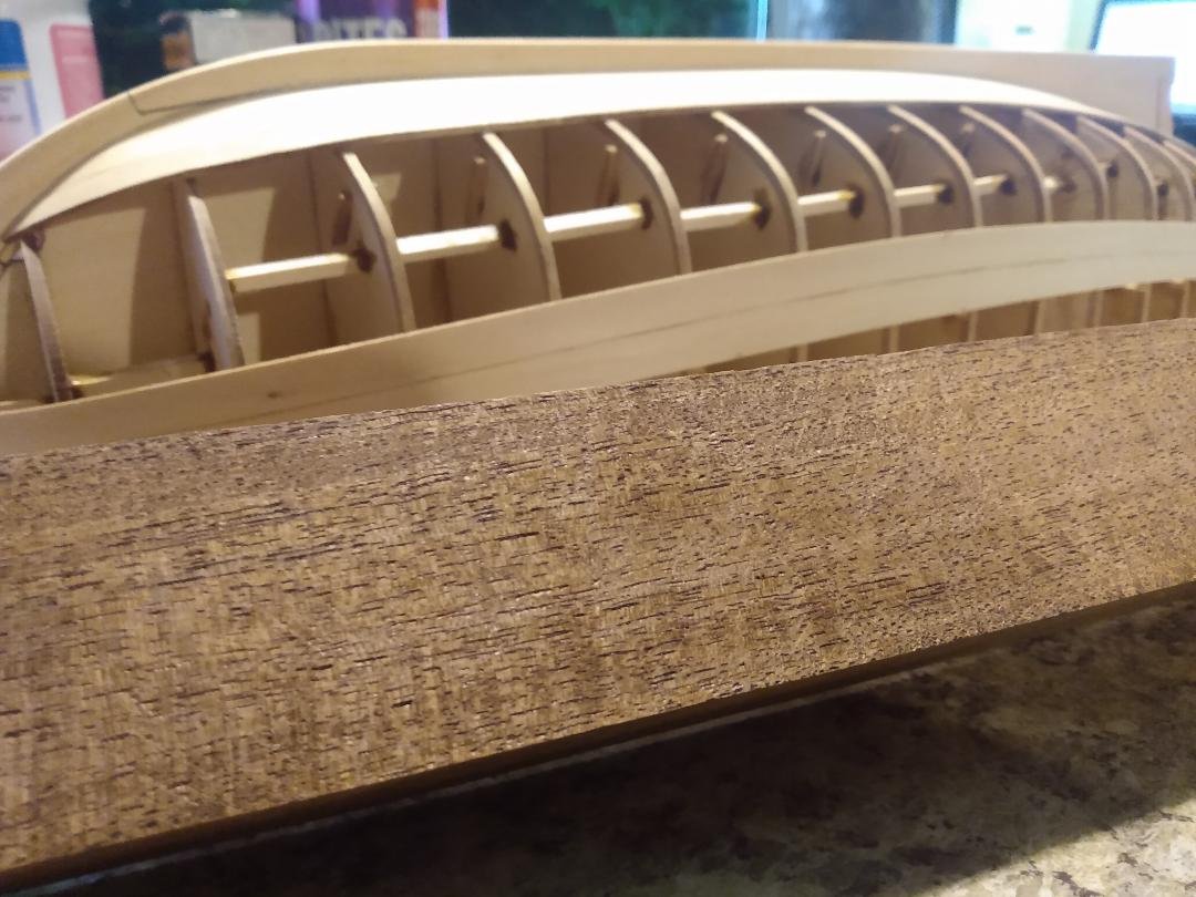
This is a chunk of Black Mesquite. I love Mesquite in my BBQ pit and now I'm going to see how much I like it on my modeling bench. I have an upcoming build and want to use this for my keel, sternpost, stempost, deadwood and rising wood components. It's some hard stuff for sure. It's going to give my tools a good workout, offering lots of sharpening opportunities in my future! 😬
-
... all being said. Just how far would 'any' true attempt at litigation be allowed to proceed, while in discovery it became 'obvious' that no mal intent, nor any desires or methods to profit from said, used 'image(s)' ever existed? Sure, there is legal 'precedence everywhere you look, but that's not the "Be All" of the laws of our land! "I object!" Perry Mason
-
You could always just paint the roof flat black, like tarpaper, then put the roof on top of 'your' roof for the summer. That should weather it pretty good and natural like! 🙃 LOL On second thought, that wouldn't work. The bird poop would be out of scale! 😲
-
Perhaps you can simply modify more popular, easy to obtain blades via a rotary tool, so they will fit? Dunno, just tossing that out there. You could also just re-sharpen the existing blade via stones and a strop, just like a straight razor... Option #3... buy some thin 01 tool steel off of Amazon and make a new, better blade, harden it with a propane torch and canola oil and hone a scary sharp edge on it. You'll have all the blades you'll ever need then! 😁
-
Use the black for undertones and build up layers of grunge on top, kinda like this. (Take note of the image file name)
-
How did you weather/whitewash the PH? Maybe you can still do the same for the roof using not so bright colors... and a bit of dry brushing.
-
"Beautiful, clean and precise!"
-
I'm glad you found that question entertaining...
-
Is there any reason that this could not be chain driven in the middle, 'between' the two wheels?
-
"I see NOTHINNNNG!... except an old, blurry photo!" 🫤

-
Make that three, or four, or whatever my current 'clueless' place in line is...
-
eBay has miniature bevel gears. Not sure what scale size your gears would need to be, but 'maybe' eBay would have some around the right size.
-
convert 2D Autocad to STL for 3D printing
tmj replied to Johnny Mike's topic in 3D-Printing and Laser-Cutting.
Autocad does 3D. Use what you got! -
Gold solder for brass
tmj replied to Richard Braithwaite's topic in Metal Work, Soldering and Metal Fittings
This stuff isn't very expensive at all and 150 pieces 2mm X 2mm will solder a LOT of parts, however! Bear in mind that no matter 'what' alloy of solder you choose... color matching is always going to be a problem... at least for us hobbyists who rarely know the exact numbers of the alloys that our parts are truly made of. We just buy stuff generically called brass, copper, etc. The true makeup of that material is usually a mystery. 2 * 2 mm 150 Pcs Gold Solder Silver Solder For Jewelry 14K Gold Solder Including E Solder M Solder H Solder Easy Welding for DIY Jewelry Making Repair Electronic Soldering 1 Gram - Amazon.com -
Lasting memories have just been made. Because of that model... neither you, nor Carson will ever forget one another! Those two bottles of rum are simply icing on a really great memorable cake! "Great job, Glen!"
- 301 replies
-
- 6
-

-

-
- Constitution
- Bluejacket Shipcrafters
- (and 1 more)
-
I was really looking into the narrowboat life and the British canals a while back. The Mrs. told me "No, don't even think about it less you find yourself wanting for another woman!" I told her I wasn't wanting a woman; I wanted a canal boat! That wasn't my brightest idea... 😮
-
Looking good!
-
I agree, however. I'd keep the moss, or whatever 'transitional-material' used tucked inside of the root mass, kinda like those Ponderosa Pines that can be found growing out of cracks in huge rocks with a bit of organic matter growing around the cracks and crevices.
- 106 replies
-
- 4
-
-
- Kentoshi-Sen
- bottle
- (and 1 more)
-
I too vote for the second one. That non-uniform slab of rock really makes it look natural and pleasing to the eye!
- 106 replies
-
- 4
-
-
-
- Kentoshi-Sen
- bottle
- (and 1 more)
-
1/8" = .125". Divide 12" inches (1 foot) by .125". This gives you 96, therefore the scale is 1/96. Everything you make, for your model, will be 96 times smaller than the part on the real ship is/was. To find the size of 'anything' at that 1/96 scale, simply divide the listed dimension, in inches, by 96. For example. If the drawing shows something to be 7 feet long... 7x12 = 84" inches. 84" inches divided by 96 = .875" long at 1/96 scale. You might need to download a decimal equivalent chart if you are not already accustomed to working with decimals. You can 'also' purchase a scale ruler and save yourself from doing the math. Hope this helps.
-
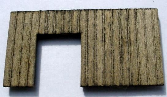
Mistake on Sternpost Planking
tmj replied to mrcc's topic in Building, Framing, Planking and plating a ships hull and deck
Hmm... It's gone! There 'used' to be a post about that here, really, there 'WAS'! 😕 -
Mistake on Sternpost Planking
tmj replied to mrcc's topic in Building, Framing, Planking and plating a ships hull and deck
Maybe you can cut off both the stern post and the planking with one clean cut, then cheat by adding a slightly wider stern post for the lower planks to butt up against?
