HOLIDAY DONATION DRIVE - SUPPORT MSW - DO YOUR PART TO KEEP THIS GREAT FORUM GOING! (Only 20 donations so far - C'mon guys!)
×


DanielD
-
Posts
645 -
Joined
-
Last visited
Content Type
Profiles
Forums
Gallery
Events
Everything posted by DanielD
-
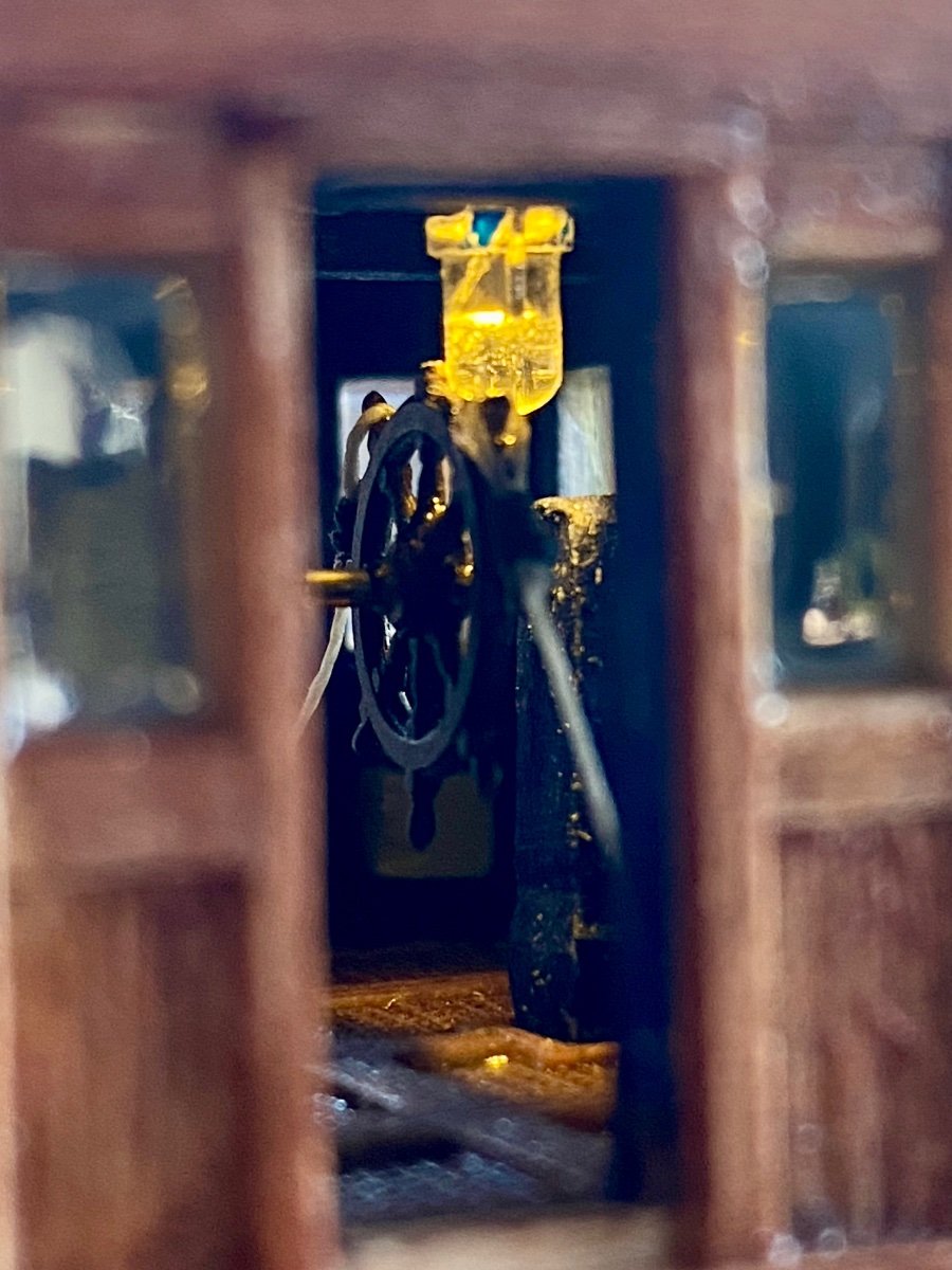
 Next up is the main bridge, complete with interior equipment and lighting.
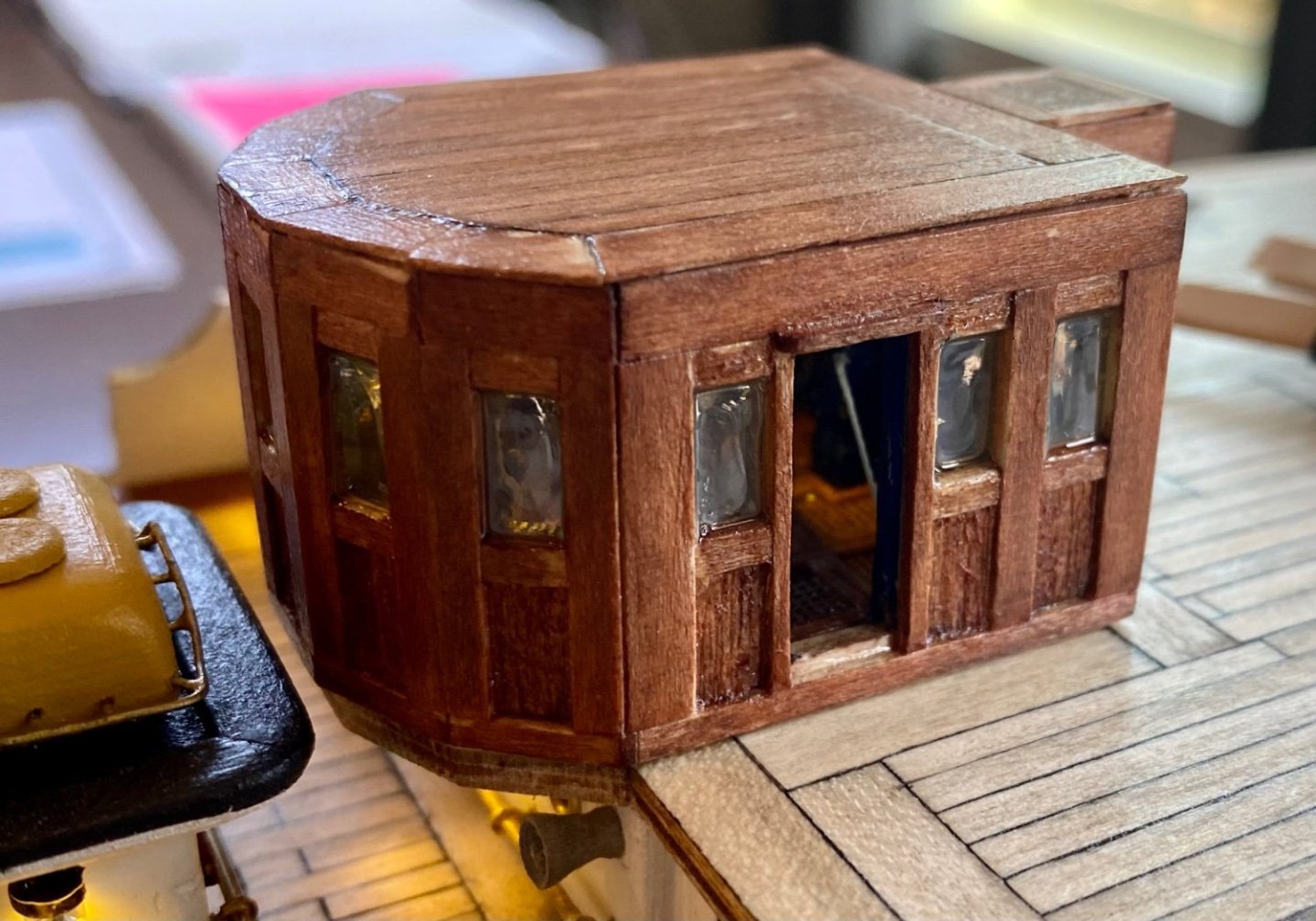

-
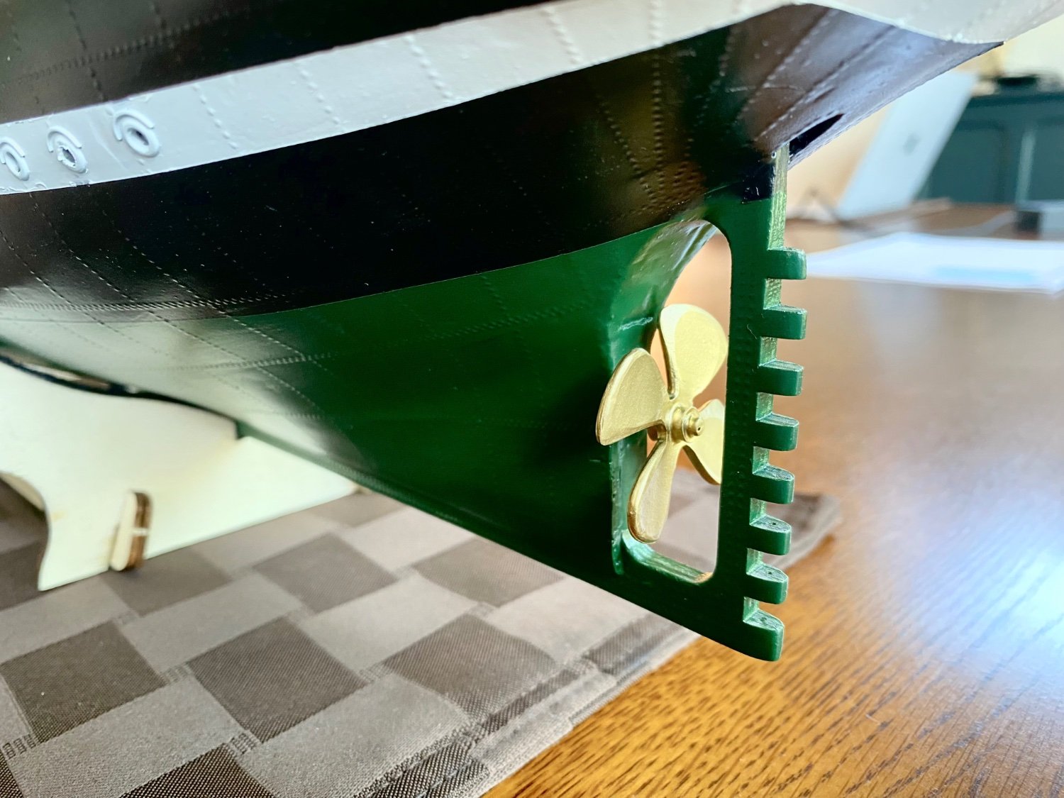
Here is a series of posts for todays visual progress! Starting with the ships propeller. OcCree calls for the propeller to be painted black; however, the dry dock images I’ve seen of the Amerigo Vespucci indicate a brass or similar colored propeller and thus the choice for my version topped off with a video of the propeller spinning under its own power. And then…I discover that I have the propeller running in reverse! There is no way to change it now as the entire ship runs on a common ground and to make the change required I would need access to the motor. Lesson learned, next time I’ll add a switch so that I can run motor forward or backwards. I guess I could possible find another propeller that is structured opposite to what I have now…hmmmm…. IMG_4479.mov

-
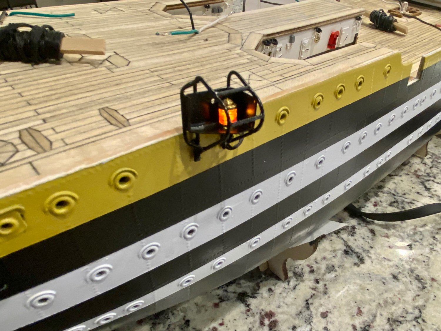
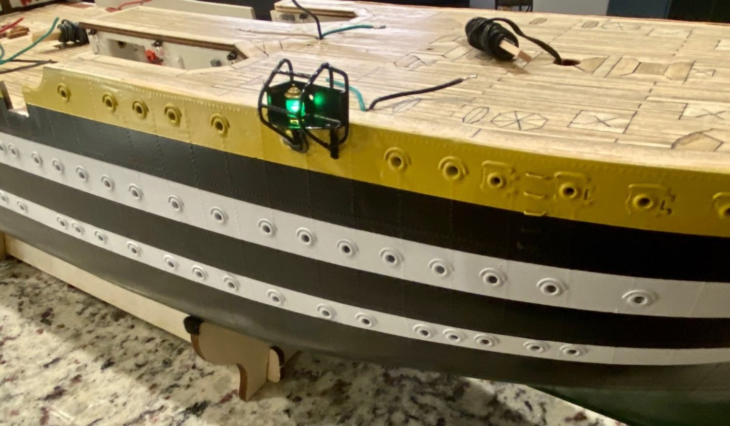
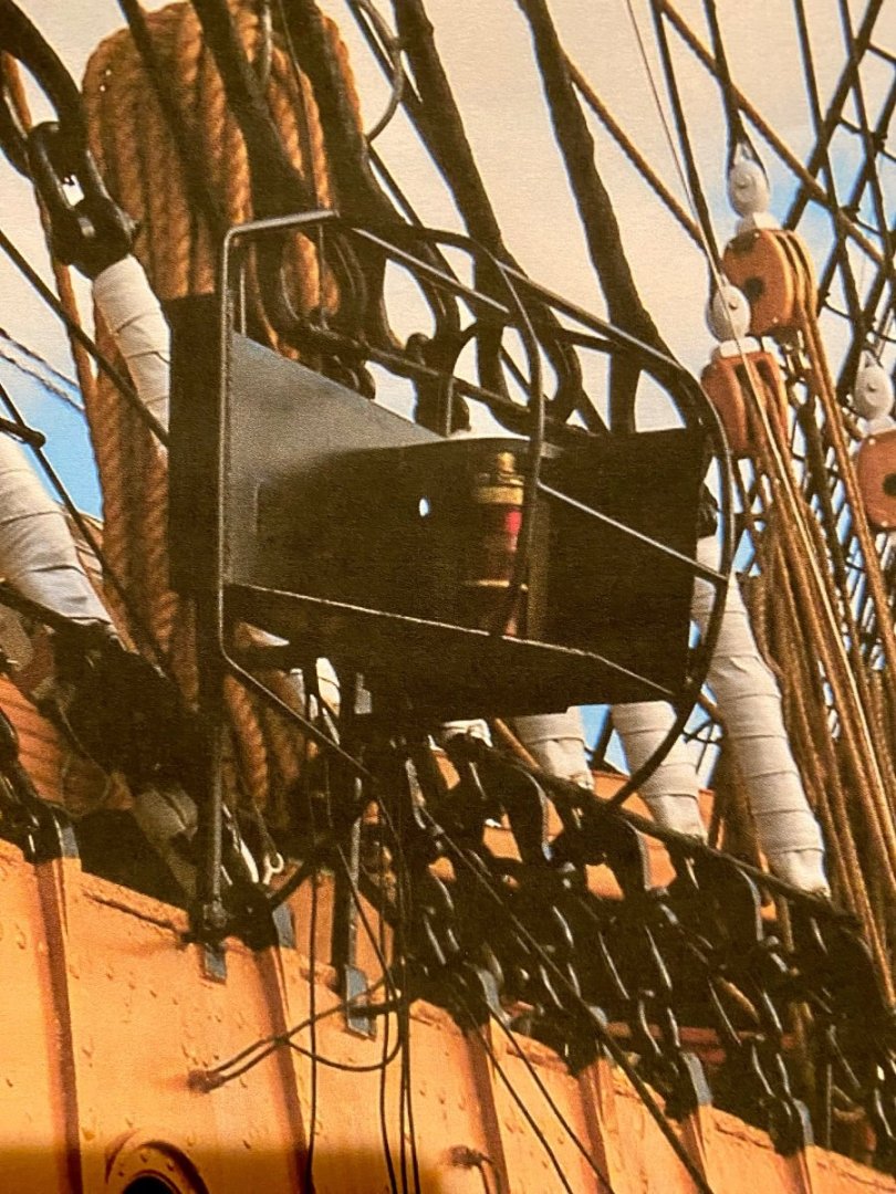
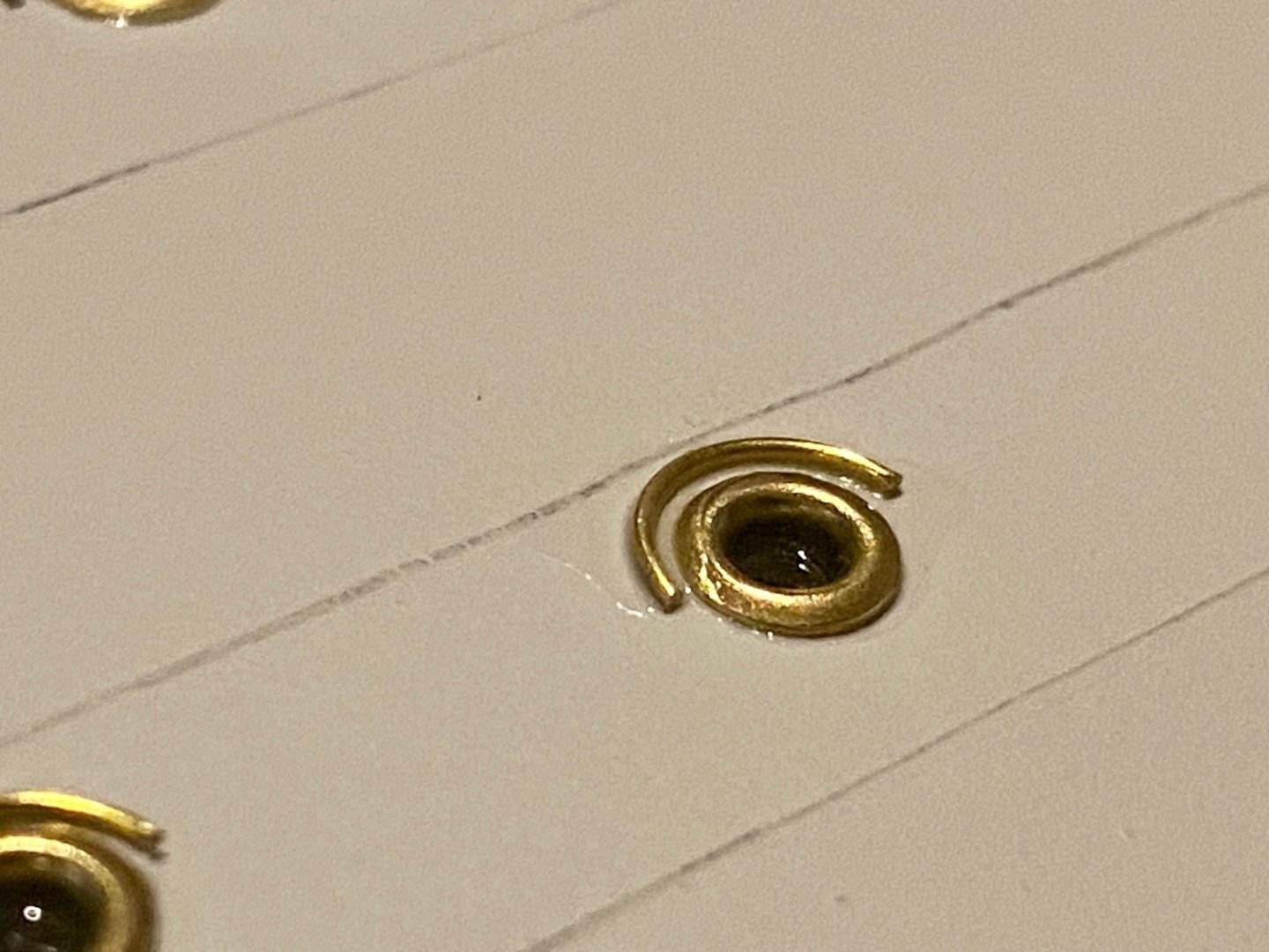
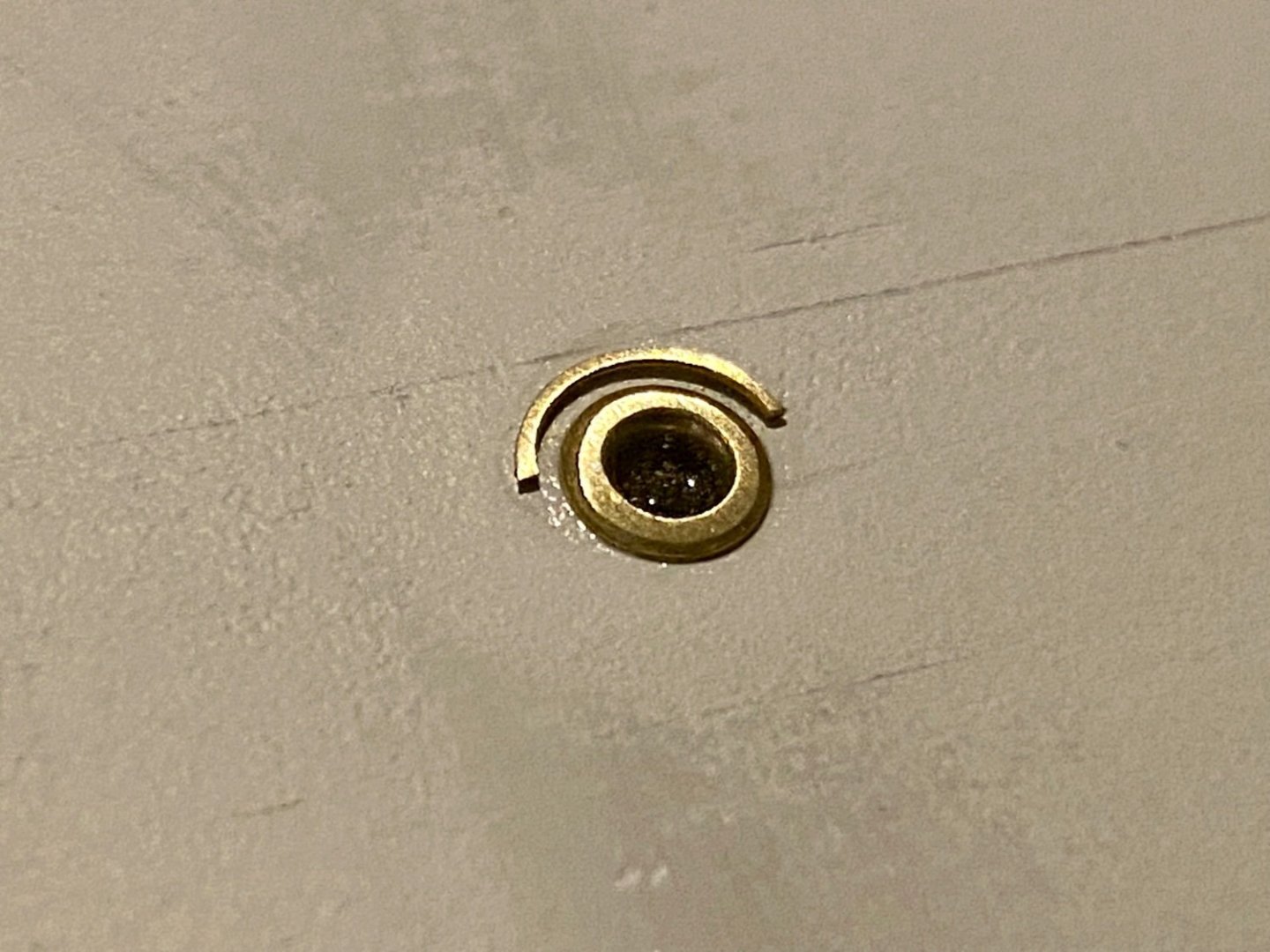
Today I did not have a lot of time in the shipyard, so I took on the easy task of installing, I hope for the last time, the port and starboard marker lighting. My quest to find images of the marker lights on the real Amerigo Vespucci was a long one. I finally found an image of where i thought the markers would be, then performed some fancy image manipulation to get the marker mount to finally show up (final image below). Keep in mind that the image you see here is only a very small thumbnail of the original picture.

-
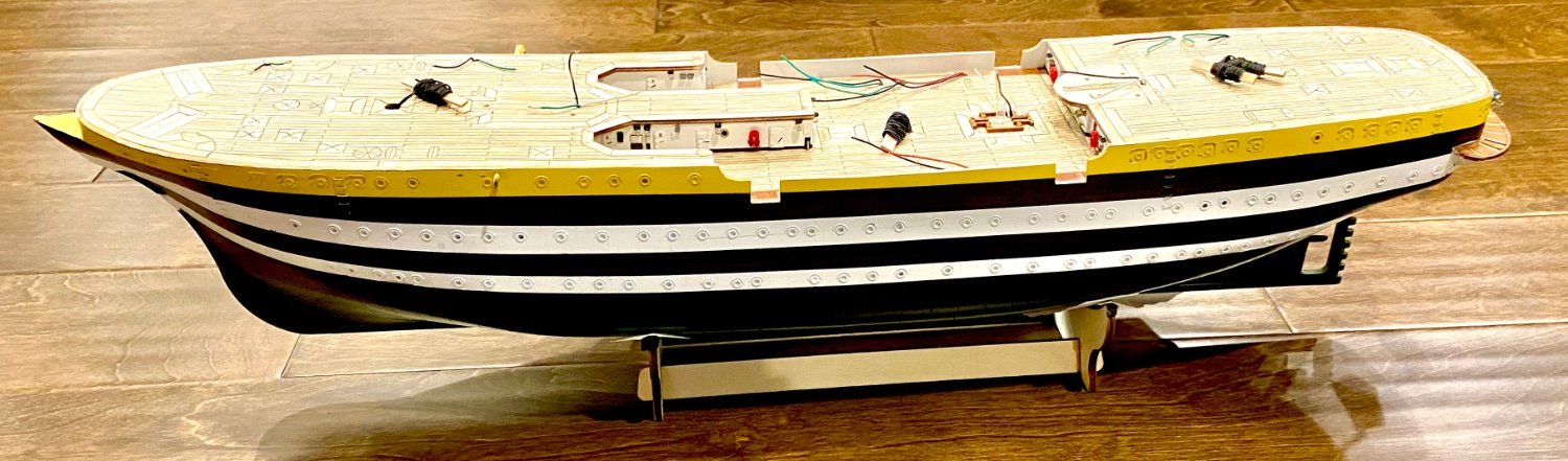
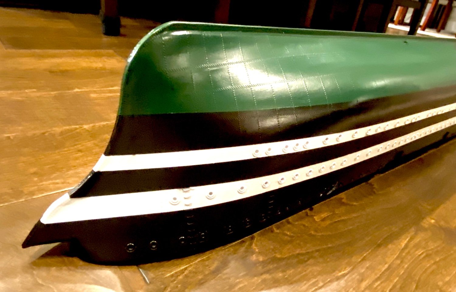
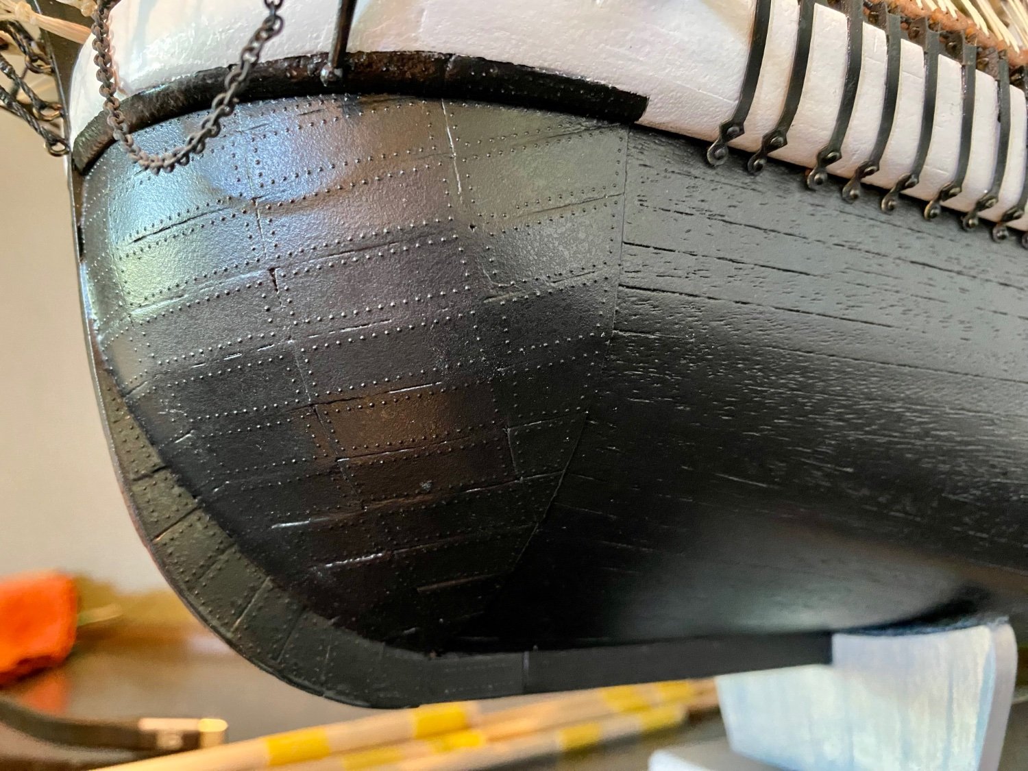
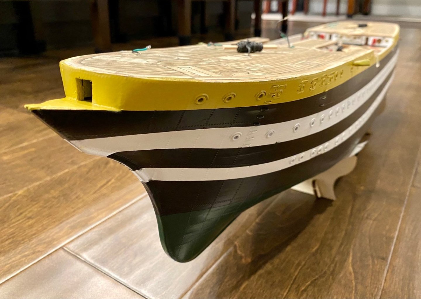
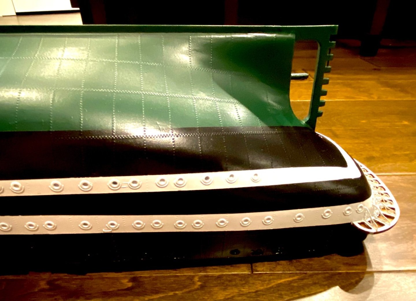
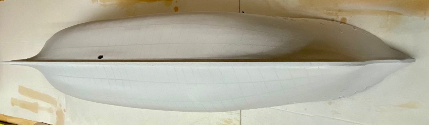
Good evening mates, the final hull paint update. All major colors have been applied and I’m very happy with the clean lines separating each paint color. A few touch ups, but nothing major.


-
Thanks for your comment. I’ve not used clear top coat to this point, and I can see some problems with it if I have to retouch something it will not match. I’ve put a lot of hard work into the detail and I don’t want to hide it, but at the same time, acrylic paint doesn’t like to stick well to brass, even after roughing the surface and proper primer. So I thought maybe, just maybe an acrylic finish would help. But I’m no paint expert.
-
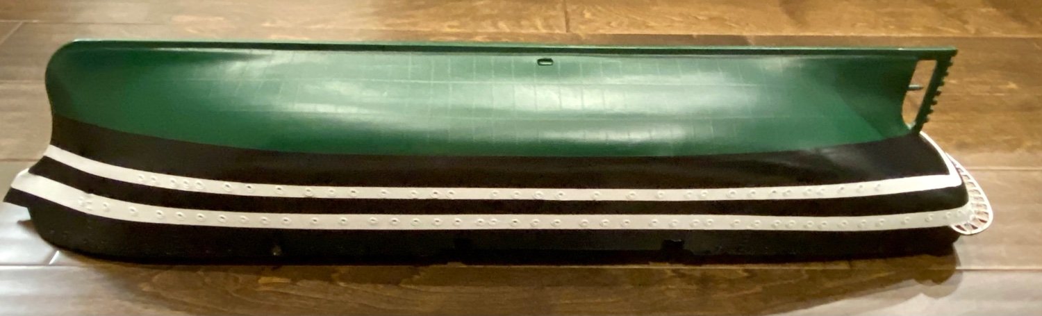
Good morning mates, here is the latest update on the hull painting…only one more color to add. Question for you experienced modelers. Once I finish the hull painting, should I clear coat it with something to better protect the paint? If so, what kind of product have you used?


-
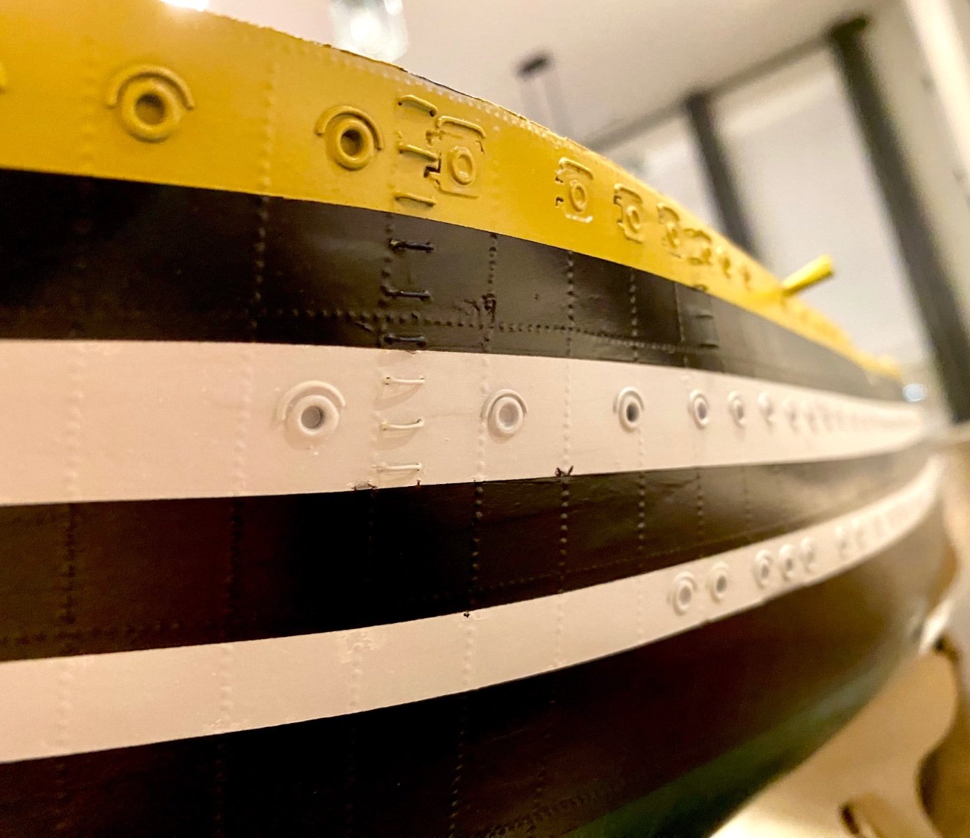
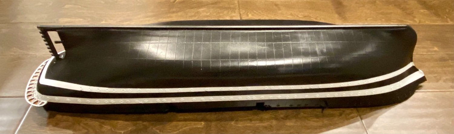
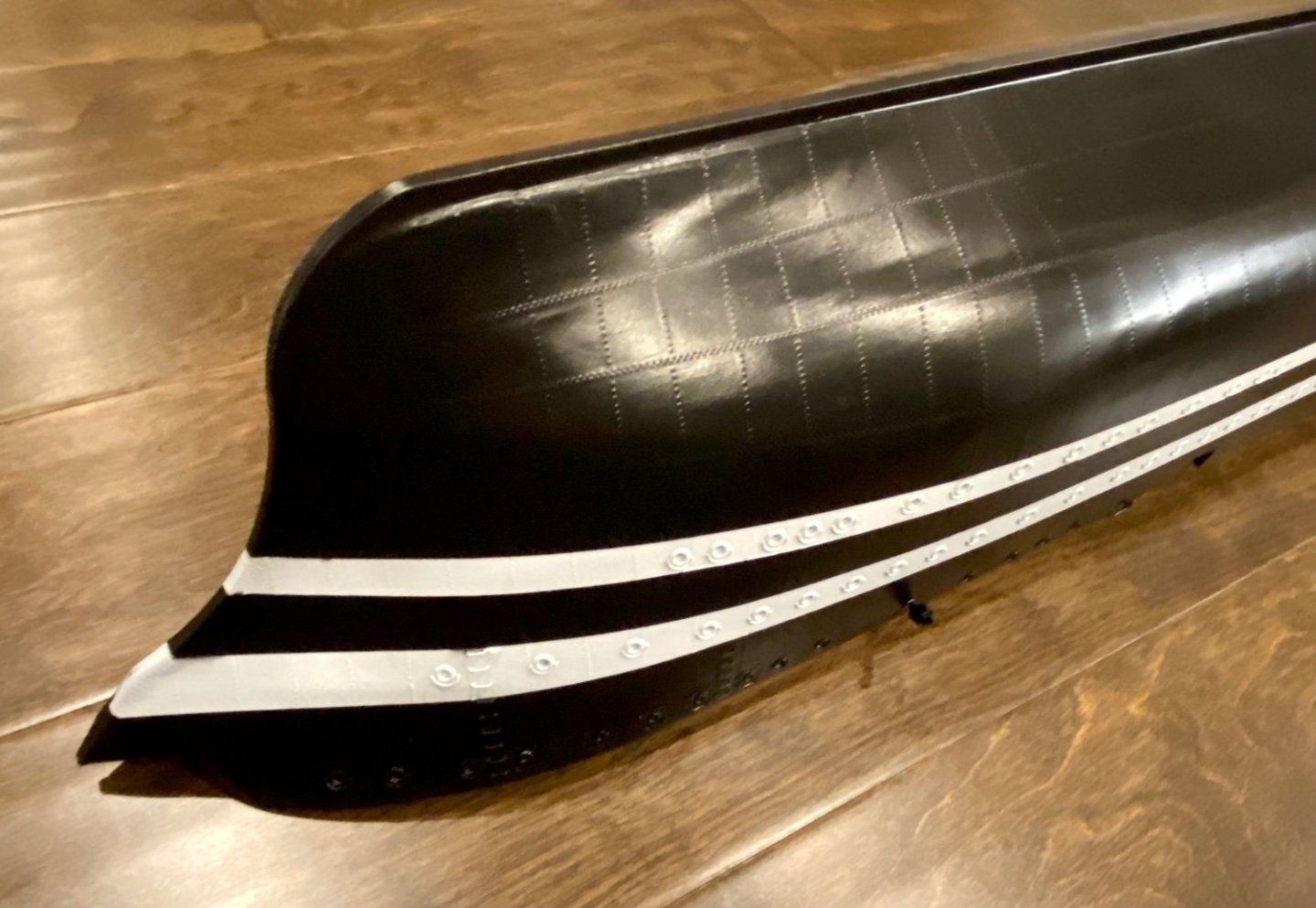
Good evening mates, this weekend was all about paint! Still have two colors to add, but need a day or two between layers to allow paint to cure. I have a couple spots to touch up, but overall very happy about the white stripes!


-
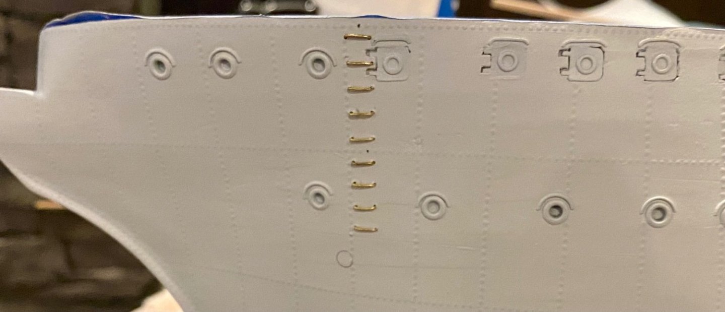
Good evening all, started the hull “ladders” (not sure what they are called). These are small round iron rungs installed on the hull as foot and hand holds to traverse from the deck over the side of the hull to a likely important area. In my first attempt, this ladder runs from the deck to the anchor hawse. These will be painted to match the area they are installed.
.jpeg.7ba0f5125b8eb484b78ec25746c30f83.jpeg)
-
Good evening mates, this week I have been working on installing the captains/stern deck with its supports. Just applied the primer with one more enhancement before final paint.
-
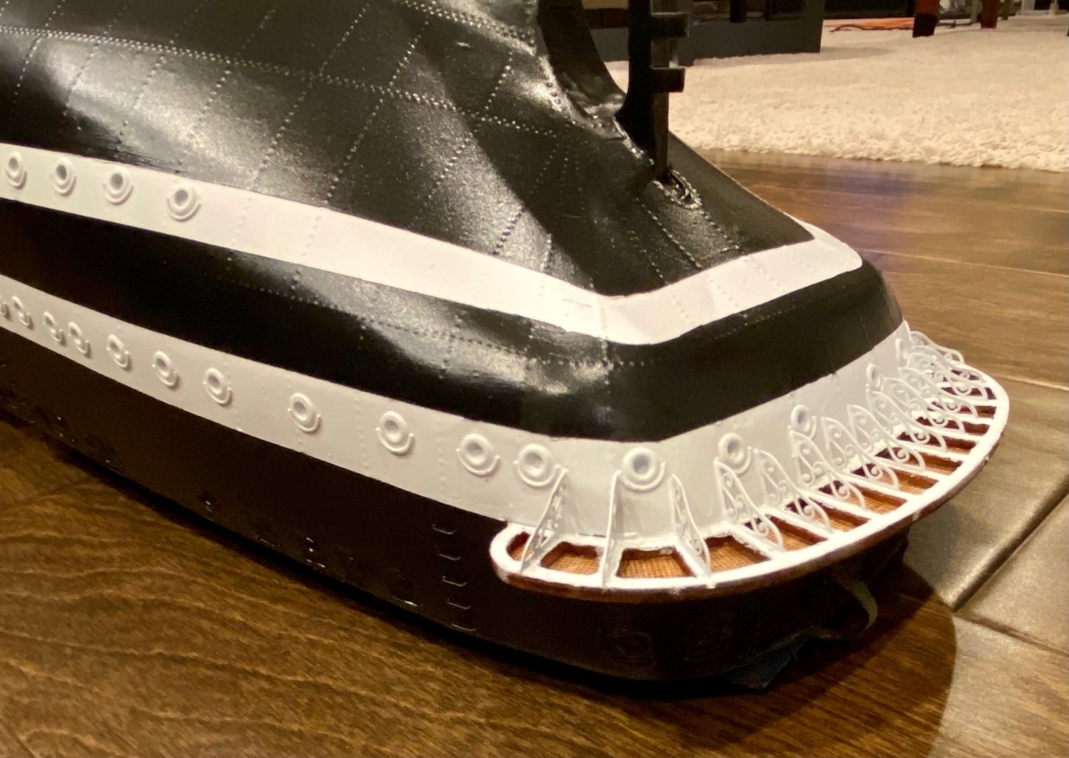
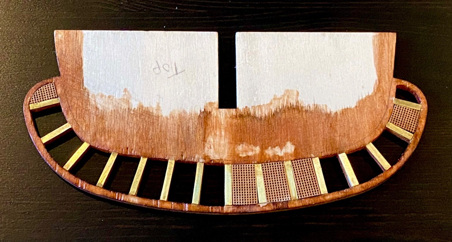
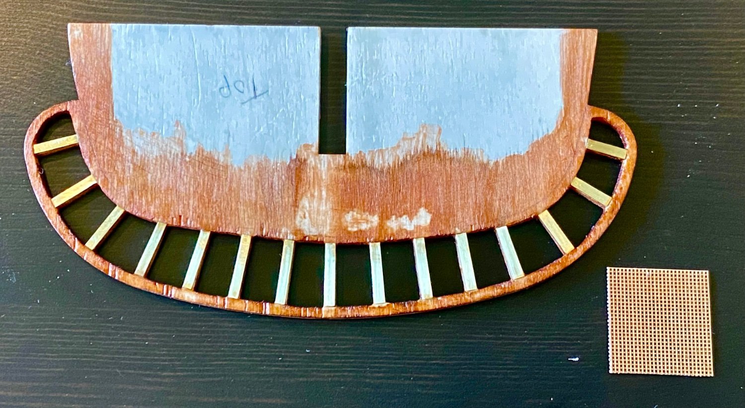
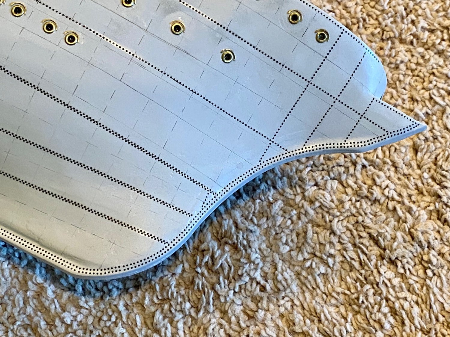
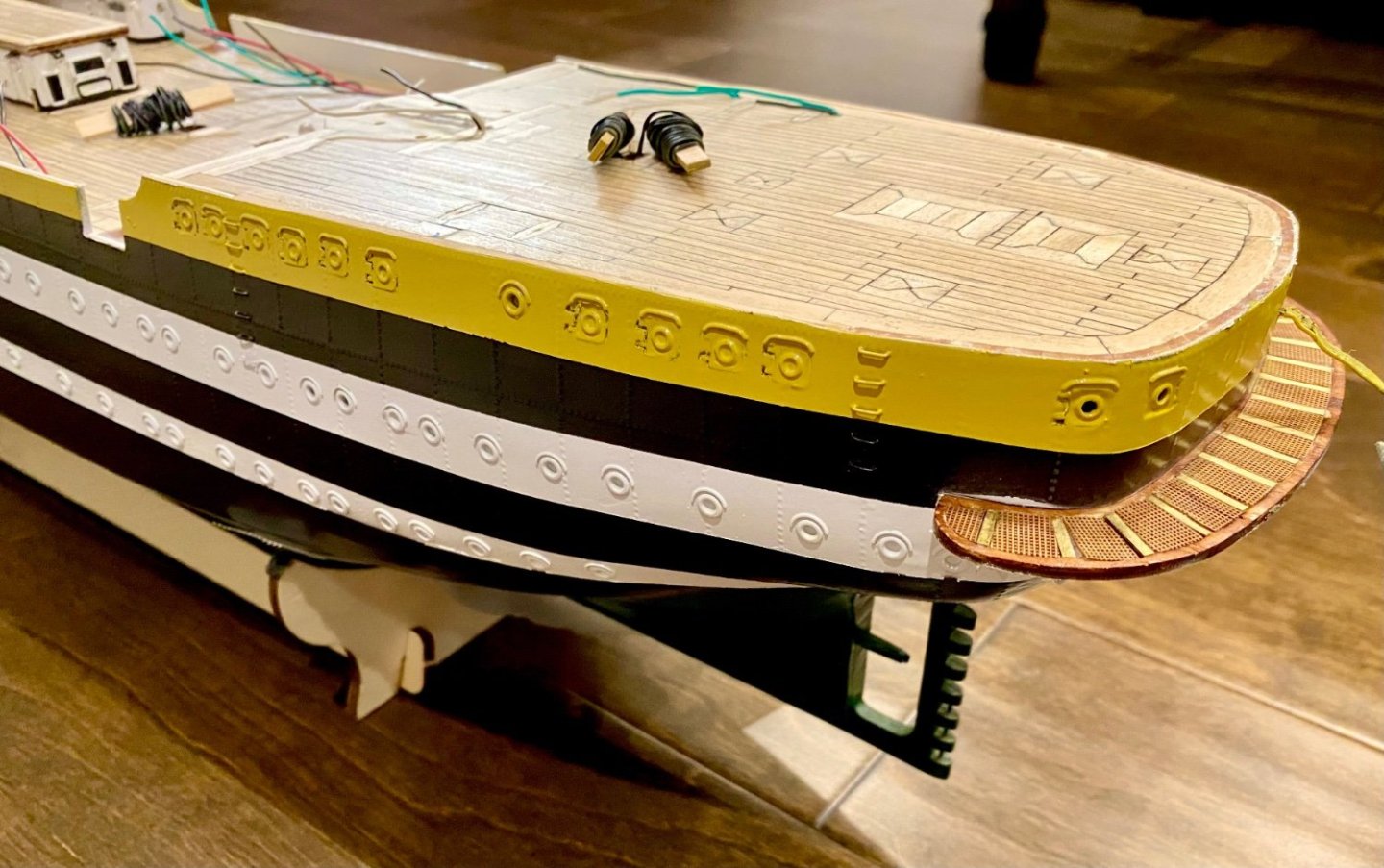
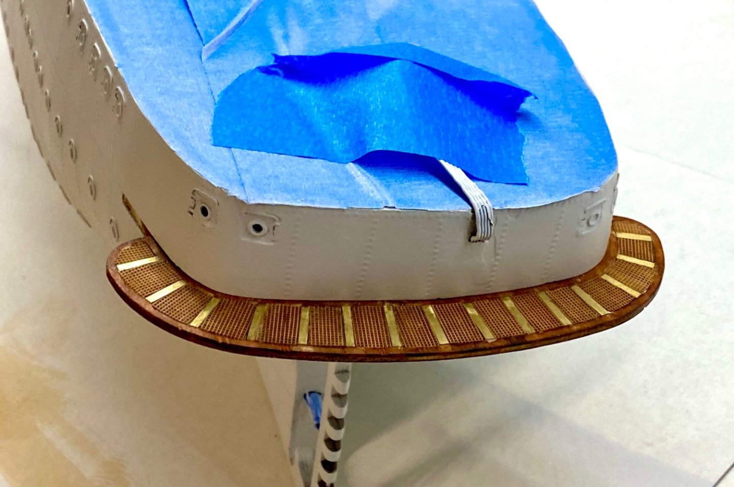
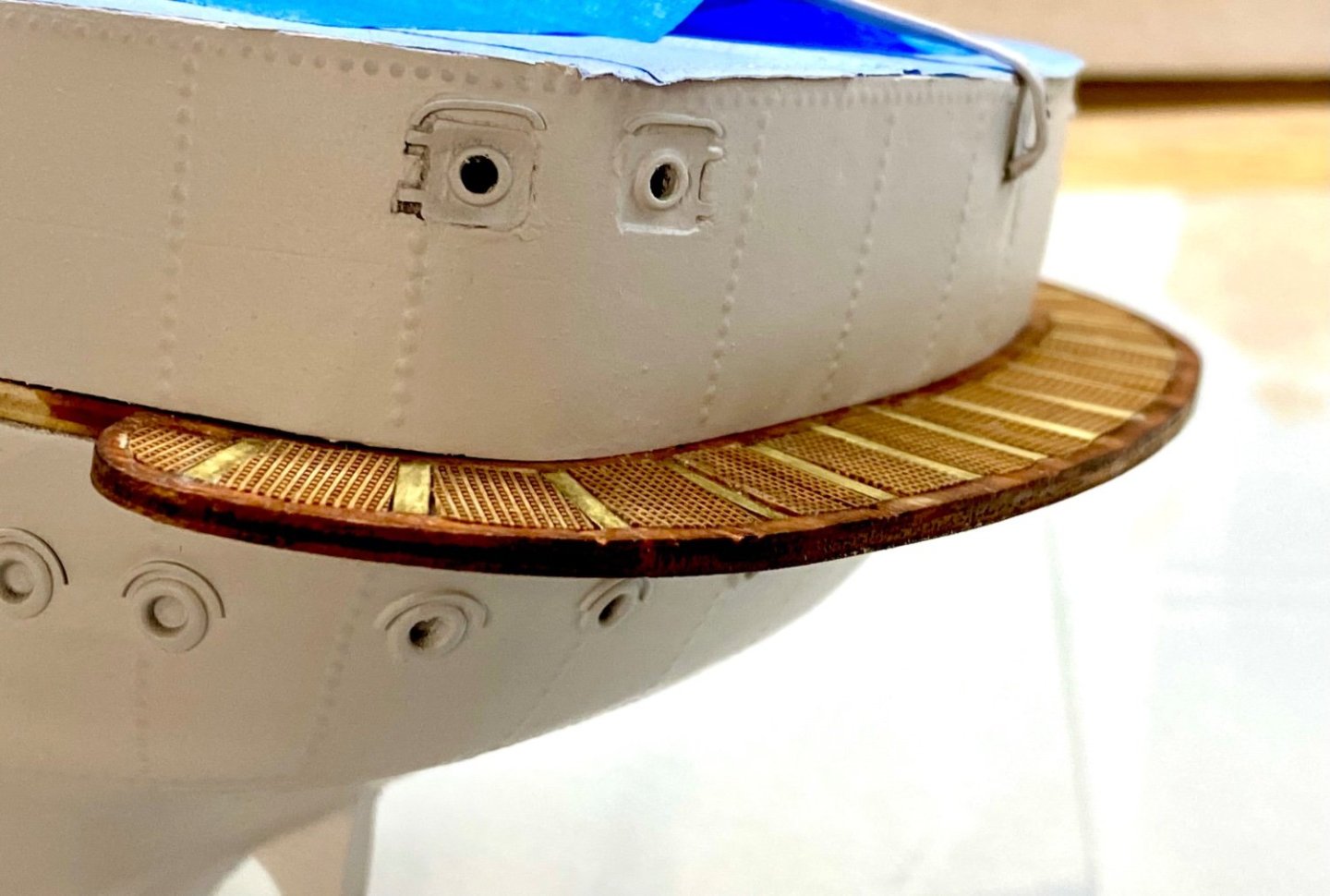
Good evening mates and for all you U.S. modelers, I hope you have a wonderful Labor Day weekend. This weekends update involves completing the stern deck (for now) with its brass inlay and micro (0.4mm) grid.
-
Quick progress update…the micro grid is very delicate!

-
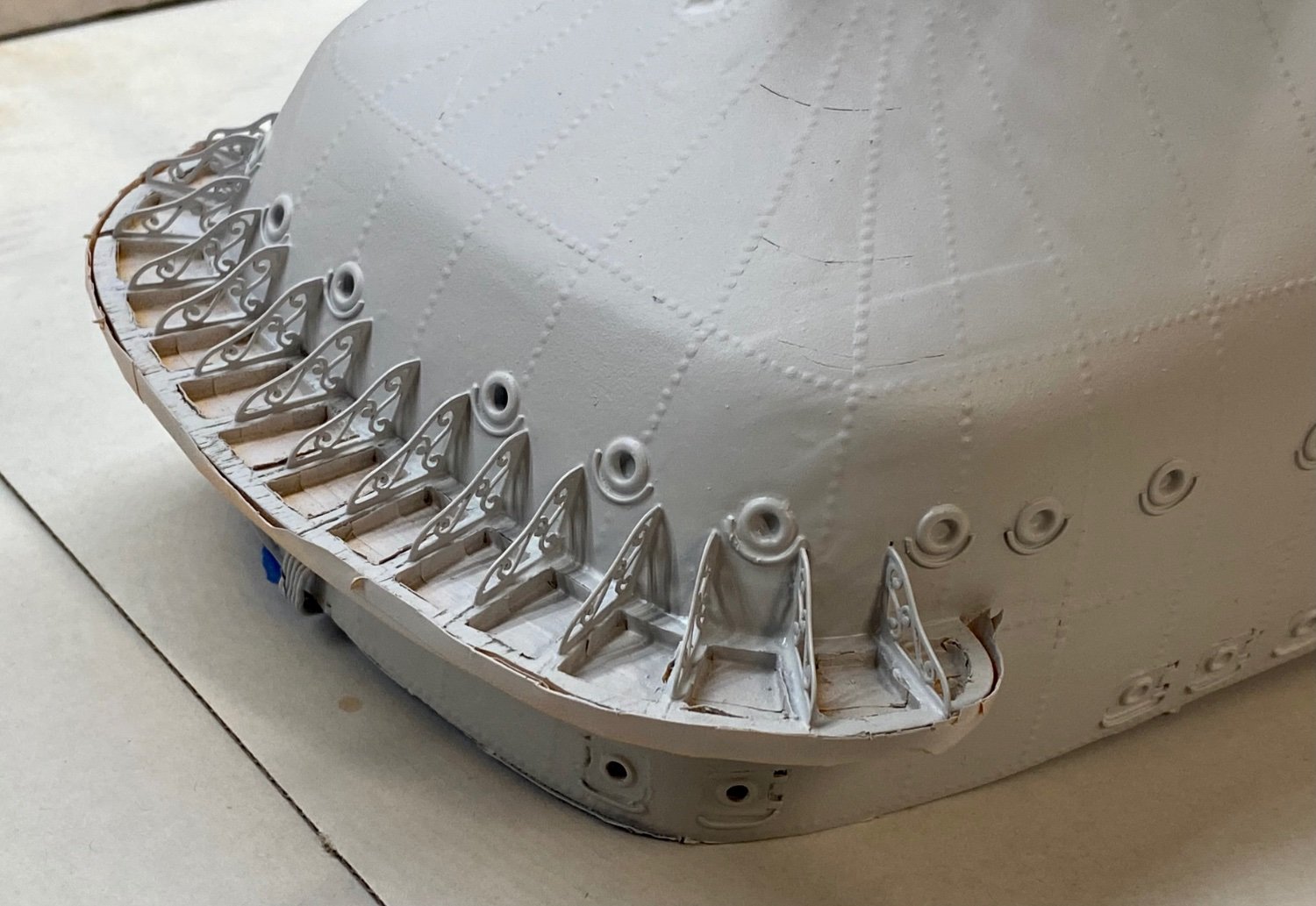
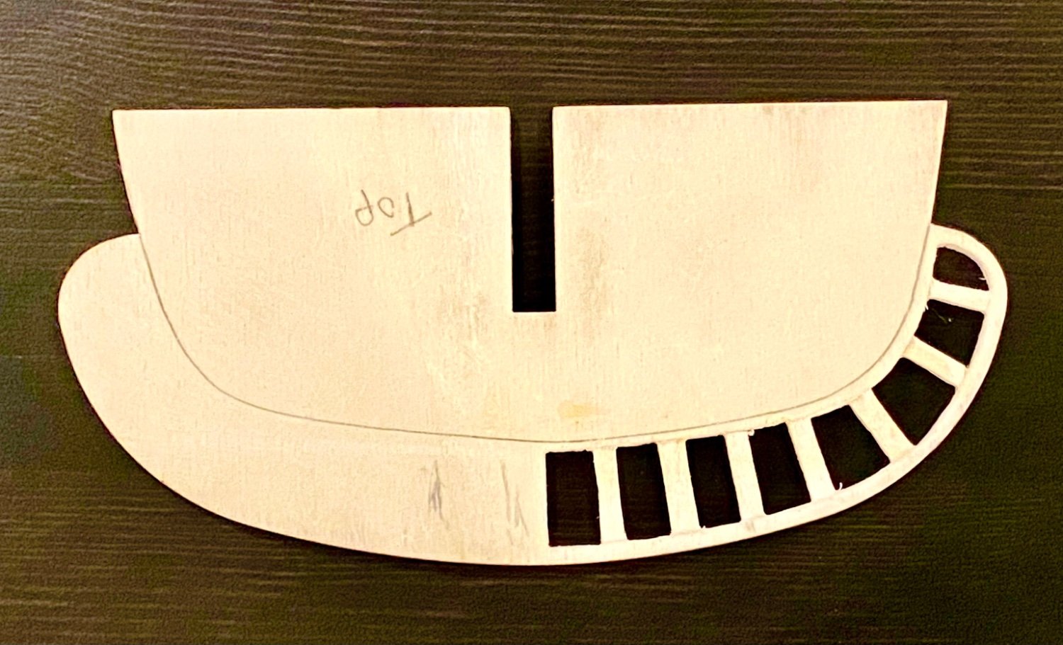
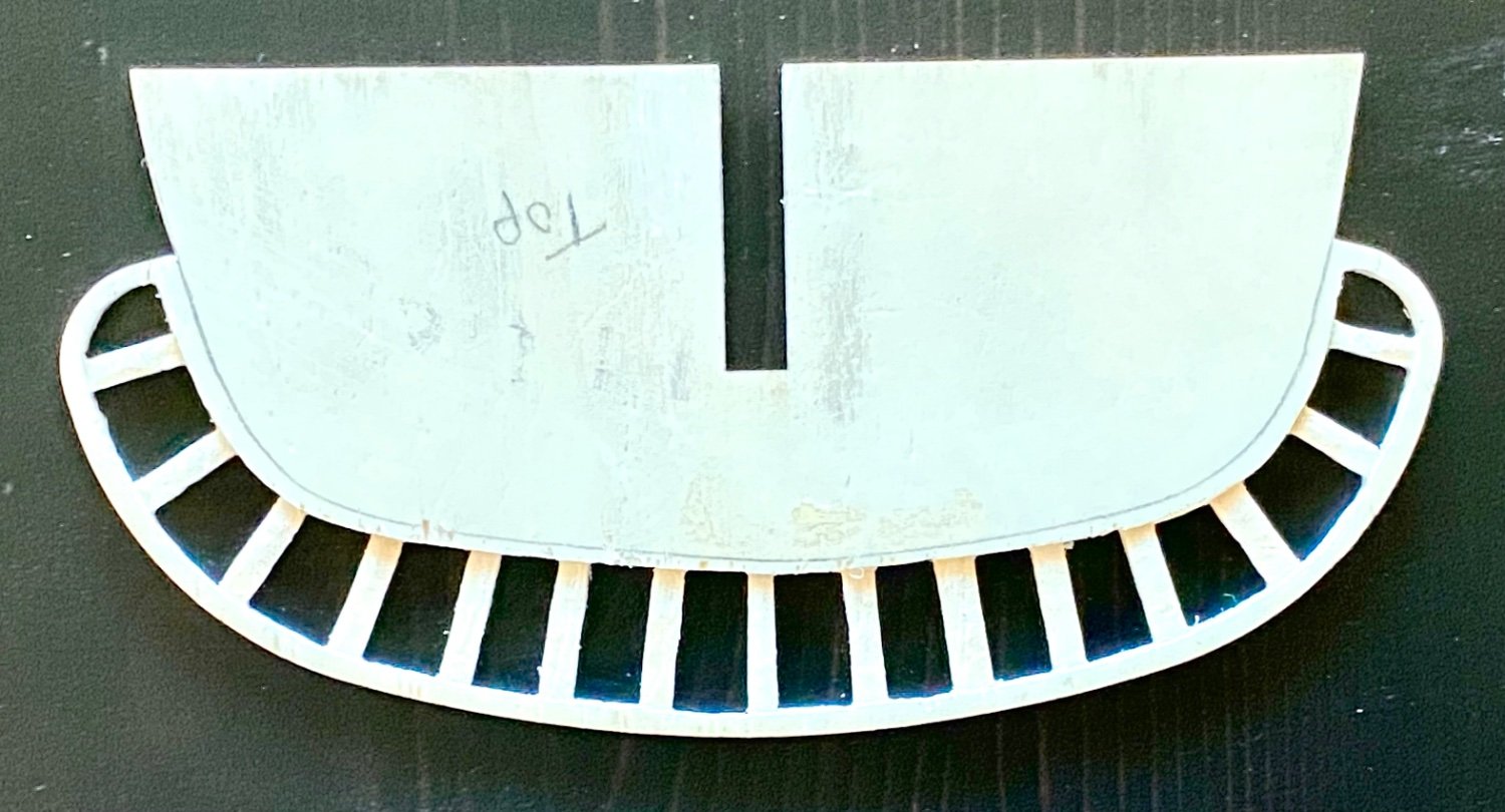
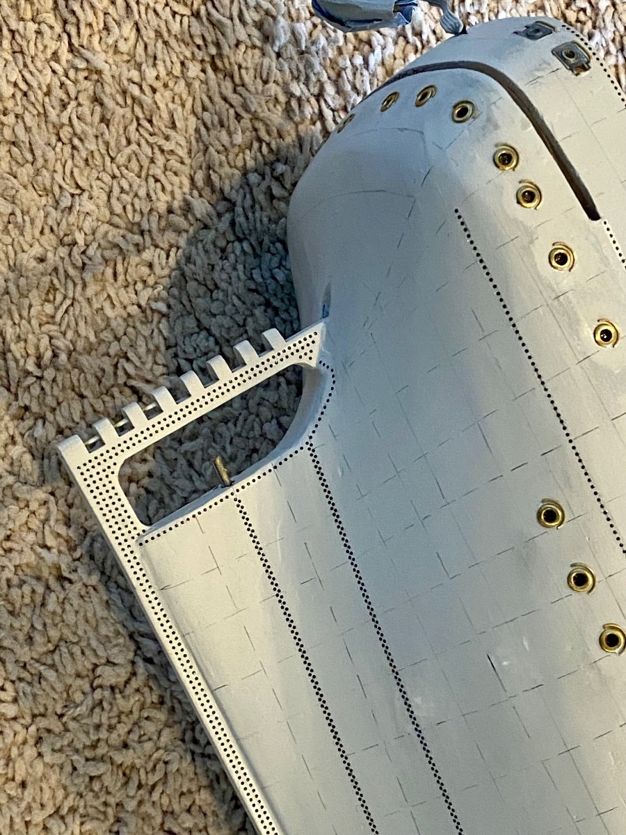
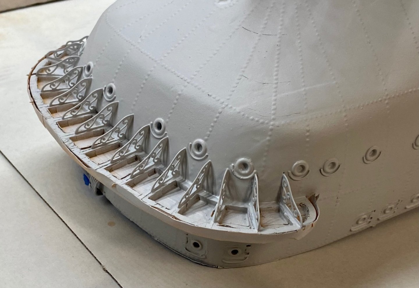
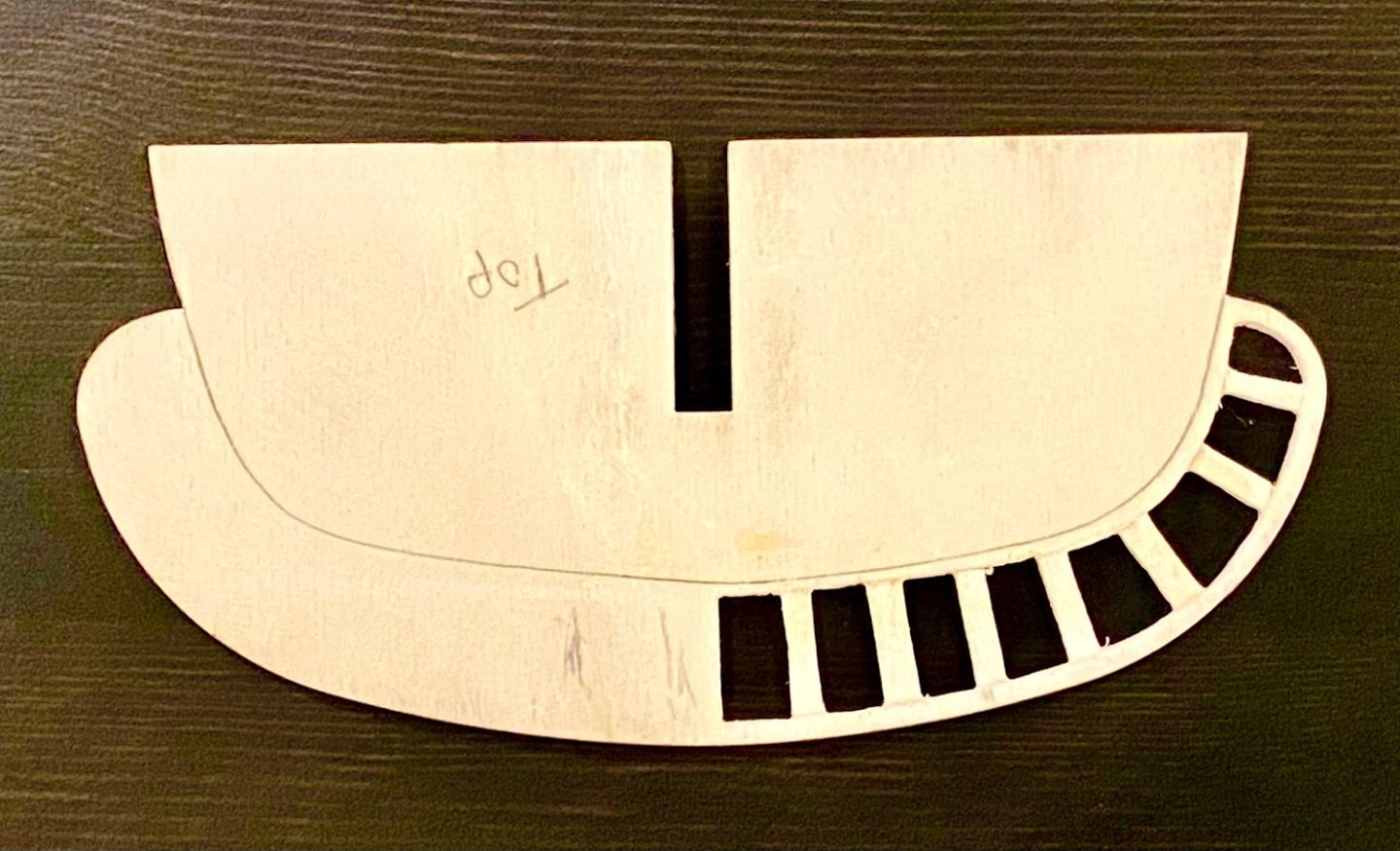
Good afternoon all, while the primer cures on the hull, I took on the task of the captain’s/stern deck. My idea is to attempt to make the deck appear more like the real AV with inlaid brass and deck grid. Below is the start of my project, with progressive images ending with the cutouts for the micro grid with the brass inlays. Next step, shape the micro grid and glue in place…hard stuff to work with for sure.


-
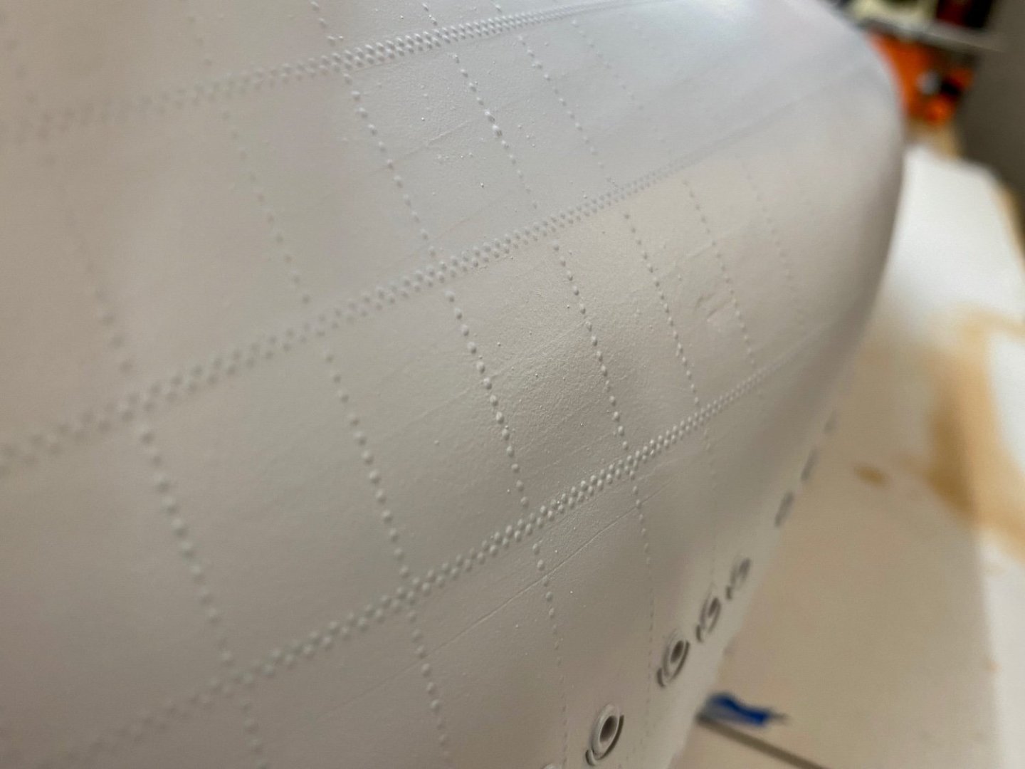
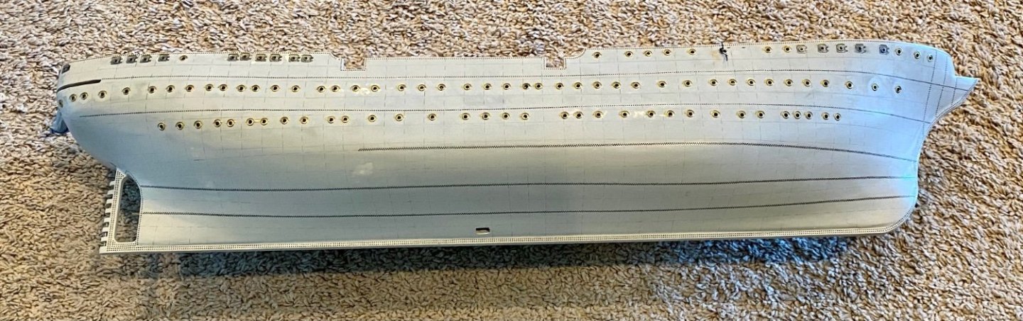
Good evening mates, another update on the hull. I have put on the last coat of primer, sealing in the rivets. So far I’m very pleased with the results.
-
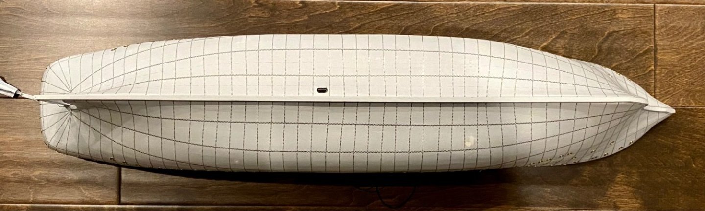
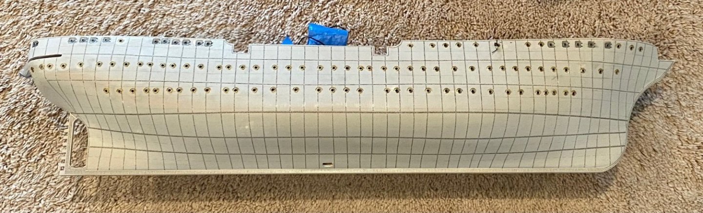
Good evening everyone, time for a riveting update 😂 (pun intended). After nearly a month of placing rivets, they are done! Well, unless I decided to place the rivets around each porthole! But that would be another week or two of riveting fun, but these would be a smaller diameter and I’m not sure they will be visible with a coat of primer, a base coat of white and then the final color. Time to sleep on it.

-
Good afternoon everyone, here is another update of the riveting progress…still slow, but making progress.
-
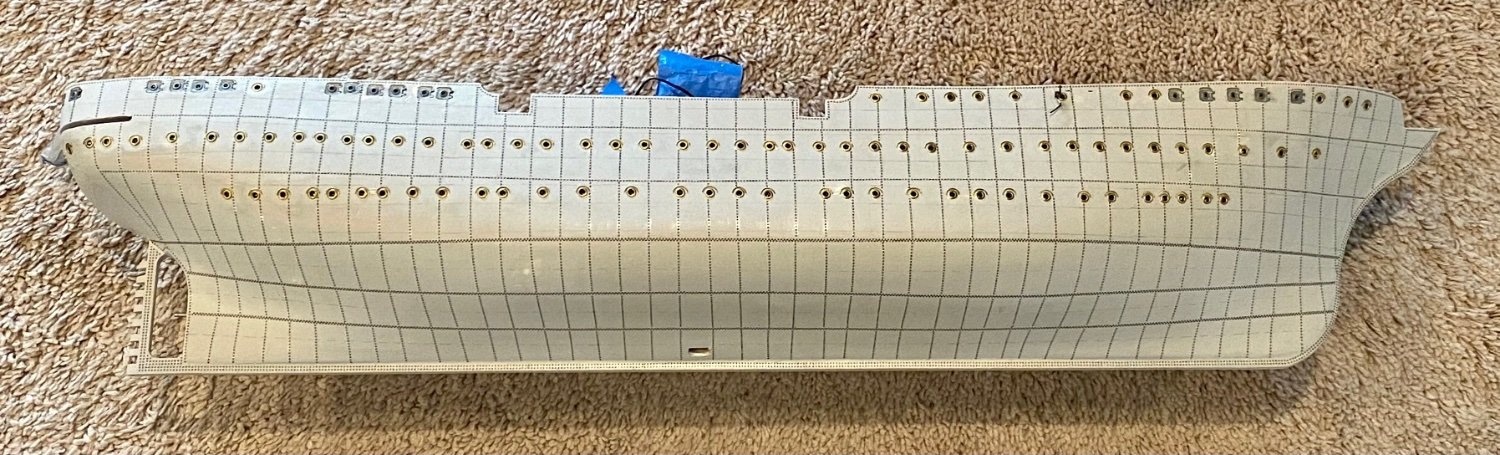
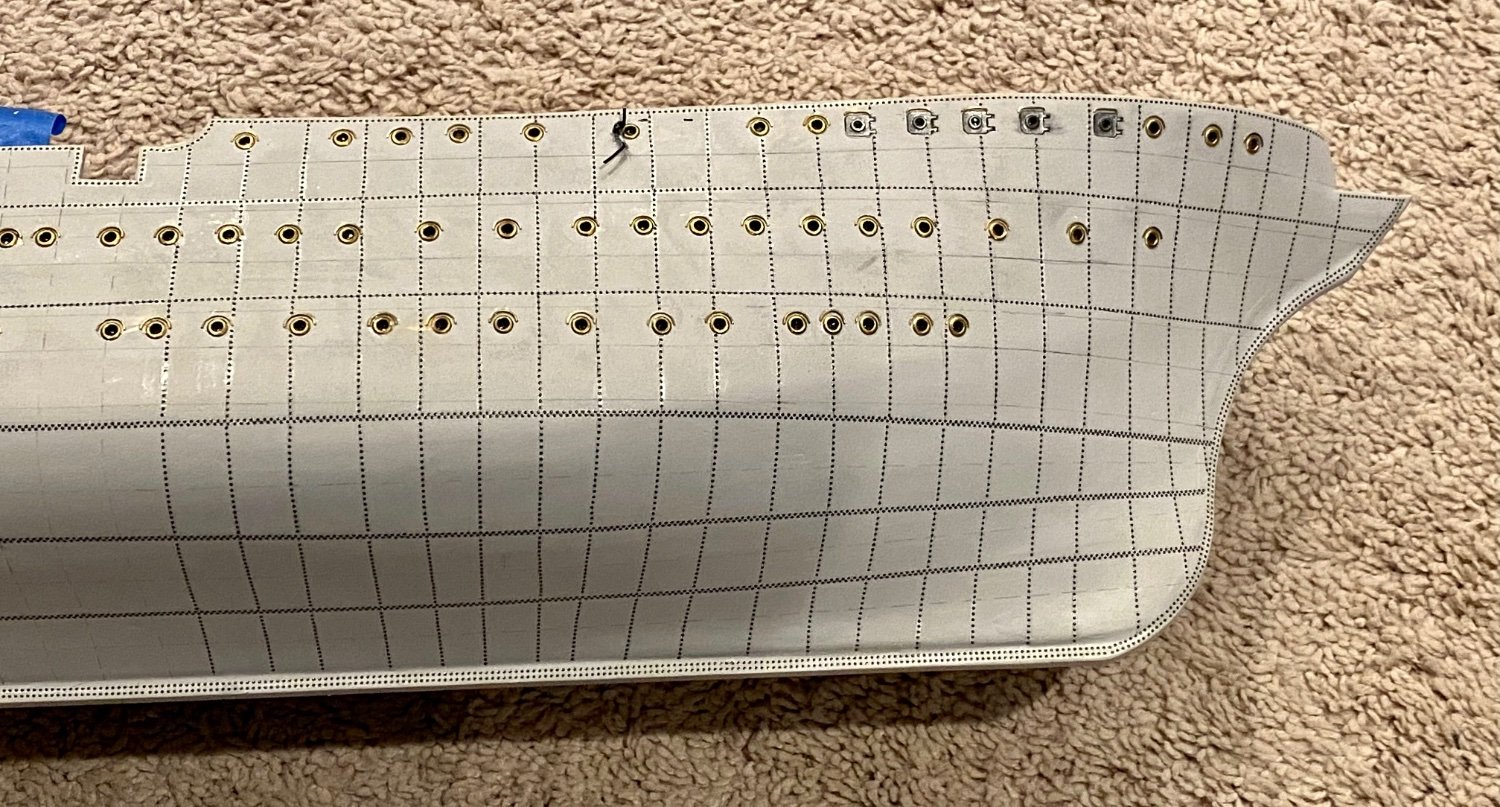
Good evening mates, time for a mile stone update. I have finally finished the rivets on the starboard side of the ship. 😄Now on to marking the port side and another week or longer attaching rivets. 😬 I’m so looking forward to the next step of painting, the black dots go away and the rivets really become part of the background.
-
Hmmm, I’ve not looked that far a head; however, in my very limited experience, shrouds are done in pairs except for the occasional last or odd numbered shroud. When passed around the mast, a portion (can’t remember the ratio at the moment) of the shroud line is “served” or wrapped to protect the line from wear as it goes around the mast.
-
Good evening all, I have spent an hour or two each night for the last few nights installing rivets and progress is, well….sloooow.

-
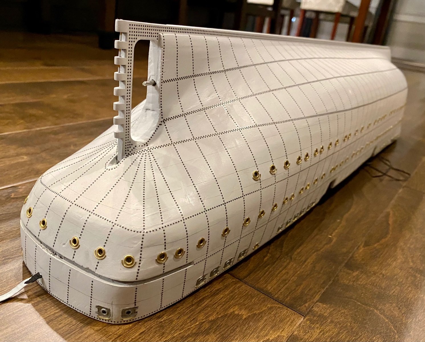
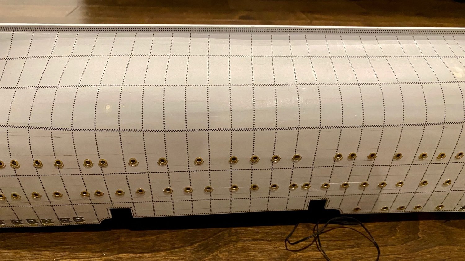
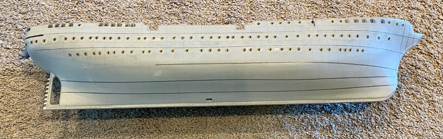
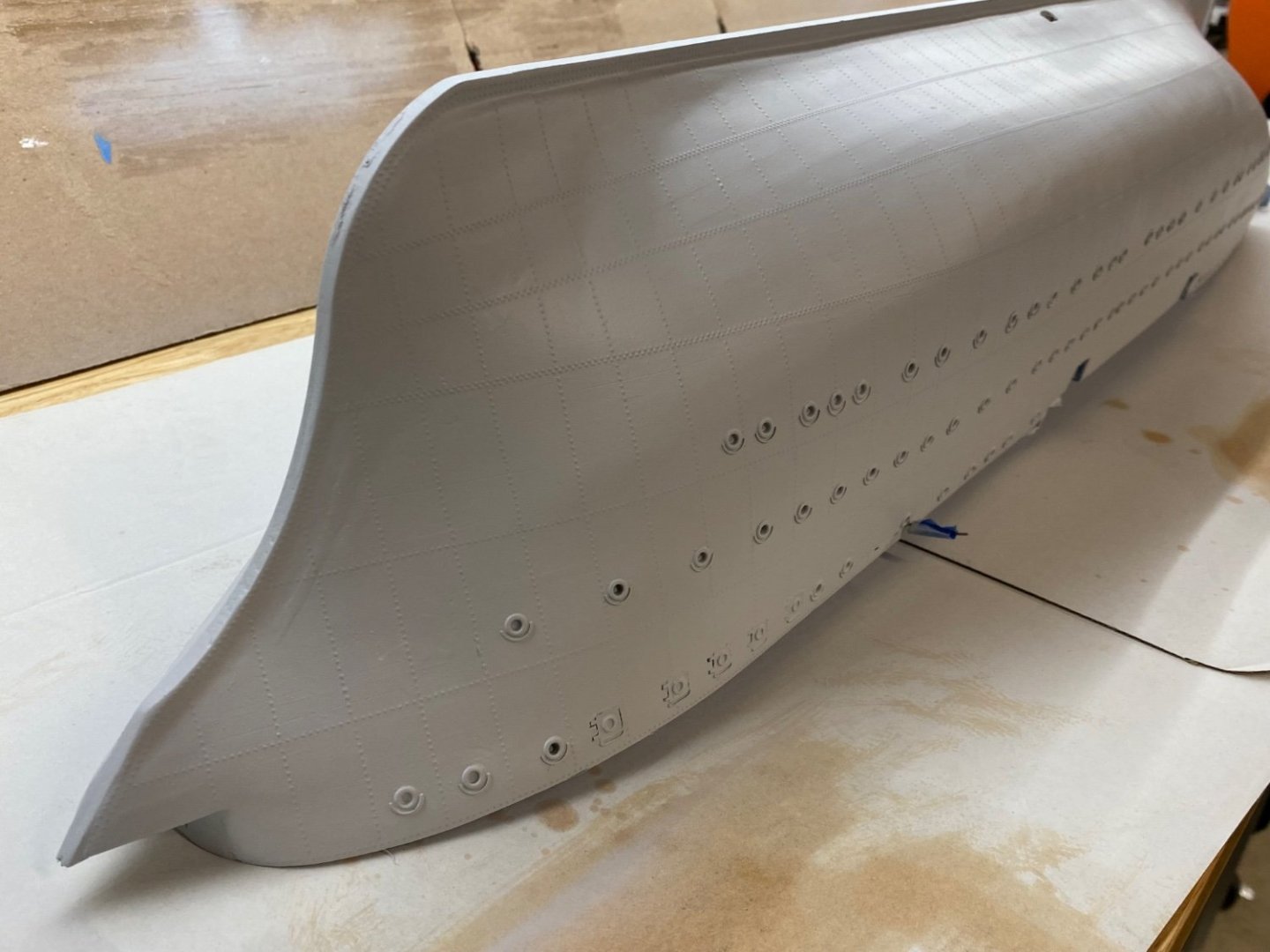
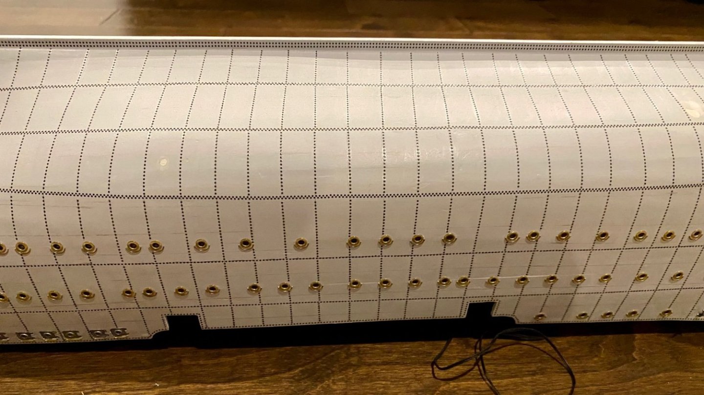
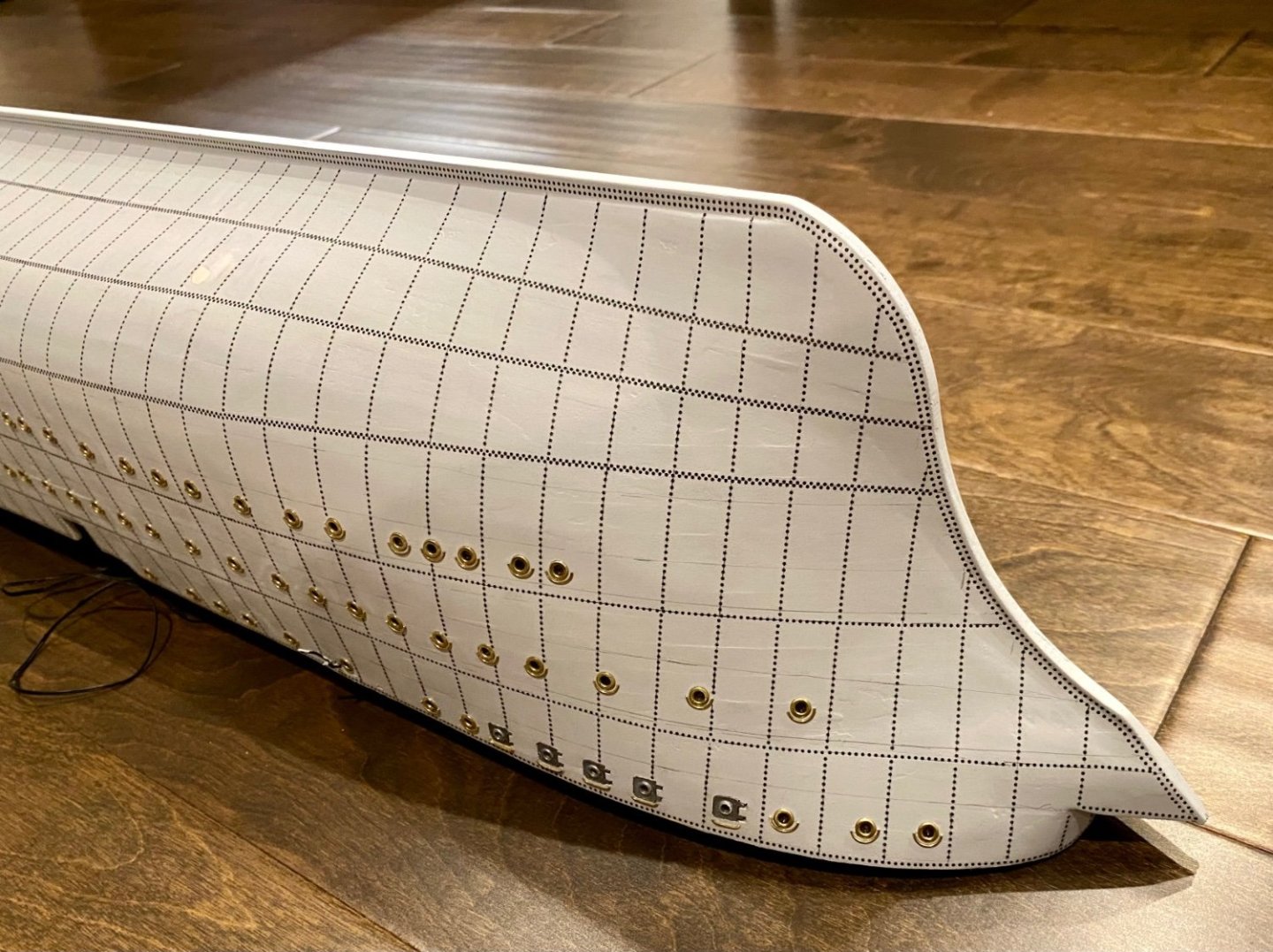
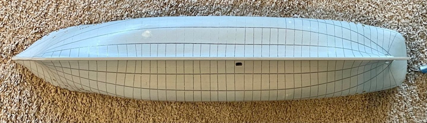
Good afternoon mates, I have started the laborious process of adding the rivets to this metal hulled Amerigo Vespucci. The rivets on the AV are very large, almost 1.5” (38mm) in diameter, or scaled to about 0.4 mm. I’m using railroad O scale rivet decals that come on a sheet in various patterns. I cut them to fit, then attach them in strips using water to free the decal from the backing material, fix them to my model using Micro Set, then dissolve the clear carrier plastic using Micro Sol. The finished product is a 0.5 mm raised dot on the side of the hull. Once this process is finished, I’ll apply another thin coat of primer before the final paint (white, black, yellow and dark green or red). Hopefully I will achieve a similar look to the real AV. I used this same technique on my HMS Terror polar explorer on the metal plates that cover the bow. I hope I achieve similar results!


-
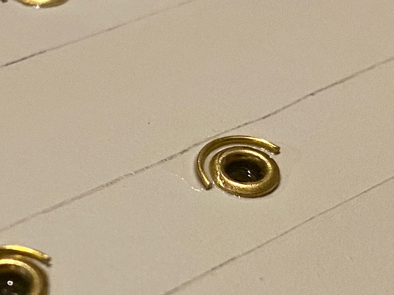
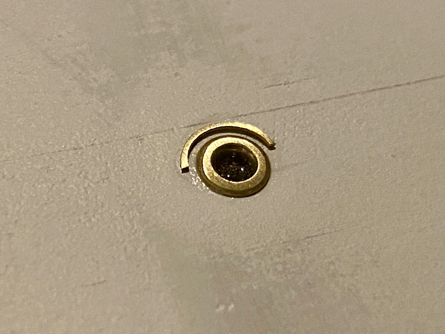
Time for another update mates, but really not a lot of visual progress. I have finished the rain gutters on each and every porthole! I have included a couple close shots to visualize the difference. i used 0.5mm brass wire and shaped around a proper sized drill, cut to achieve the look on the AV, then glued in place with very thin CA glue, wicking up the excess with a paper towel. I thought that would be it; however, when I looked close at my installation, I realized it looked like I glued on a piece of wire. Next I sanded each gutter to flatten the edge so it looked more realistic. A few more attachments for the hull, then another round of primer before paint. Before sanding, just the wire rain gutter. After sanding, a more square look.
-
Mike, I do plan on installing sails; however, this time around I’m planning on furled sails as I’m planning on a spectacular night light display, and…I’ve never done furled sails before (experience). My last ship, HMS Terror by OcCre I hand made my sails. It’s a lot of work, satisfying, but…did I mention it’s a lot of work.
-
Good morning mates, it's been awhile since my last post. I have been busy out in the yard, so little time in the shipyard. However, I have been trouble shooting a recent issue... Last week, I was demonstrating the ships lighting features to a visitor and then turned on the motor for the screw. It ran for about two seconds then stopped! I checked the voltage, the wiring, everything external that I could check, and still nothing. I was feeling a bit disheartened as at this point there is no way to get to the motor it's self. Last night I was looking over the model, a bit frustrated, just toggling on/off the button for the motor, when it all of the sudden started working again! Here is what I think is happening. The unit I used is a geared motor so that the revolutions are about 30 per minute (don't want to hurt anyone). In this particular device, the gears are exposed and I did not take steps to protect the gears. As you can see above, the Amerigo Vespucci has a ton of port holes that have to be drilled in through the hull. This will unavoidably cause wood chips to enter into the hull. I believe that one of these small chips temporarily was wedged into the gears of the motor, which stopped it from working. At least that's all I can think of as the wiring is well secured and not likely a problem. Lesson learned, the next time I use this motor in a ship where I won't be able to access the engine compartment, I will take steps to protect the exposed gears. Oh well, all is now as it should be. UPDATE: I have completed the port hole rain gutters on the starboard side and now mass producing the ones for the port side. Should have some visual updates later this weekend.
-
Beautiful work, I’ll tag along to see the finish!
- 282 replies
-
- 1
-

-
- Bluenose
- Model Shipways
- (and 1 more)
-
I'm considering this ship, I'll follow along.
-
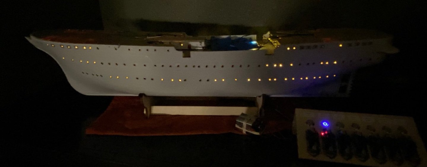
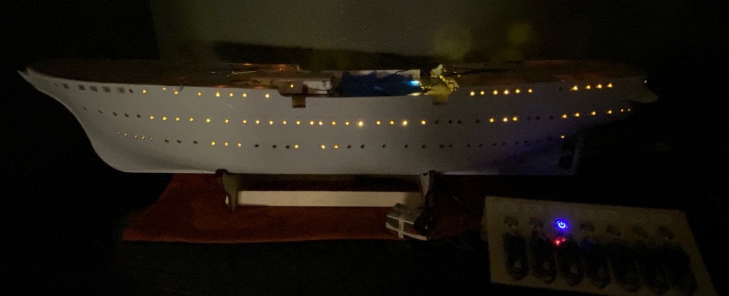
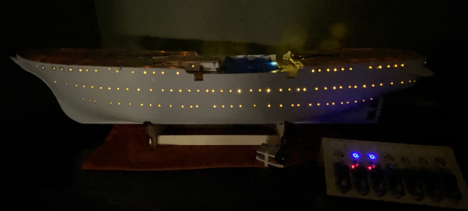
Good evening mates, no progress on the AV today, but I did take a couple of low light shots that better show lighting effect.