DONATION DRIVE - SUPPORT MSW - DO YOUR PART TO KEEP THIS GREAT FORUM GOING! (91 donations so far out of 49,000 members - C'mon guys!)
×


Mirabell61
-
Posts
7,409 -
Joined
-
Last visited
Content Type
Profiles
Forums
Gallery
Events
Everything posted by Mirabell61
-
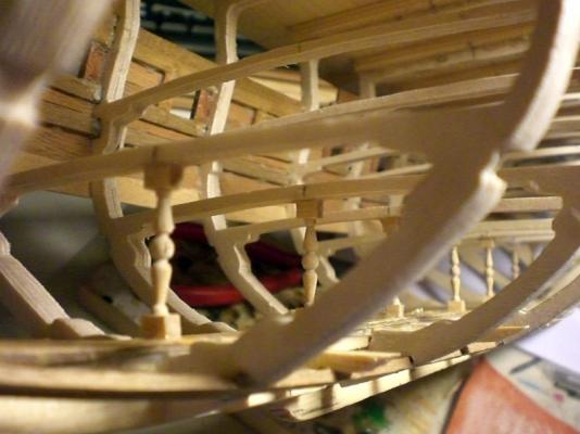
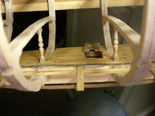
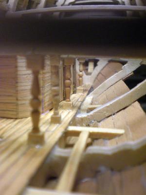
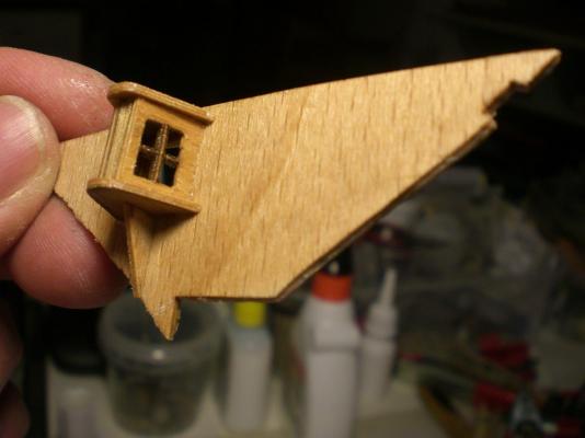
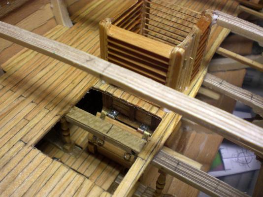
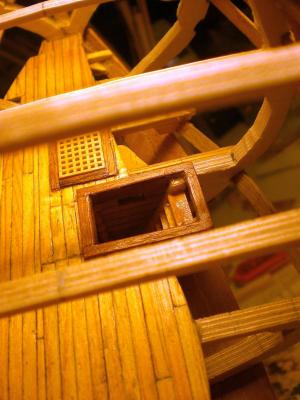
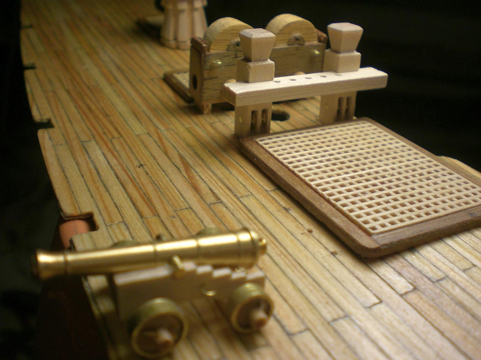
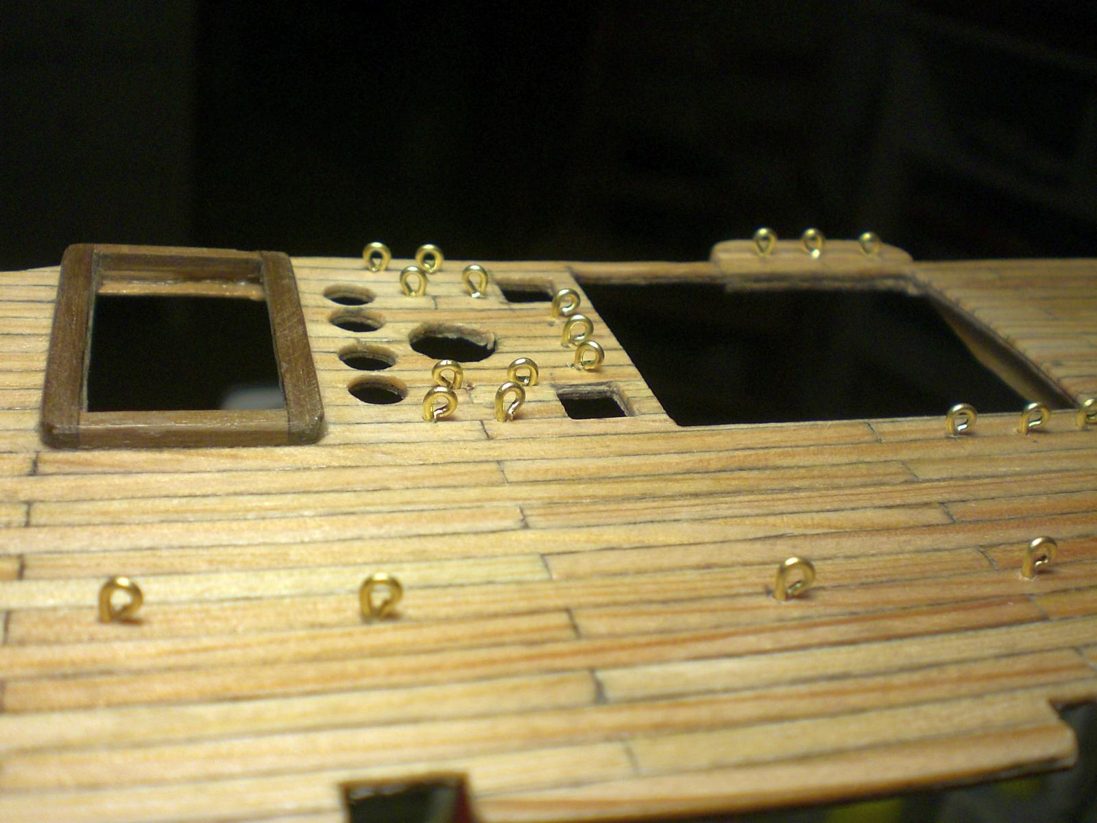
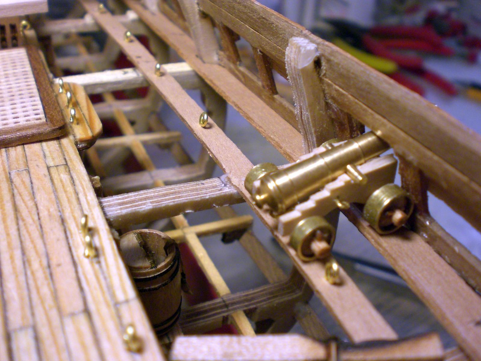
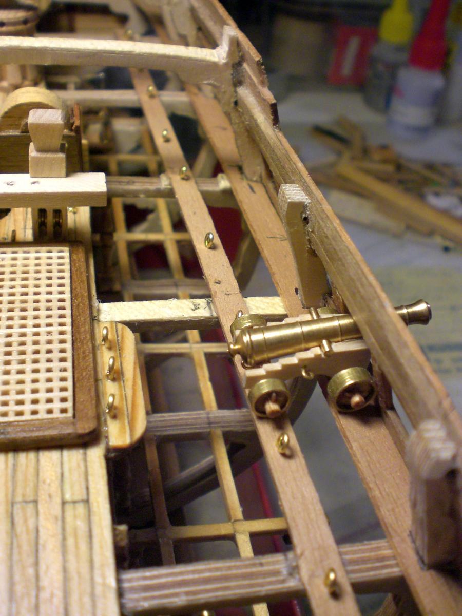
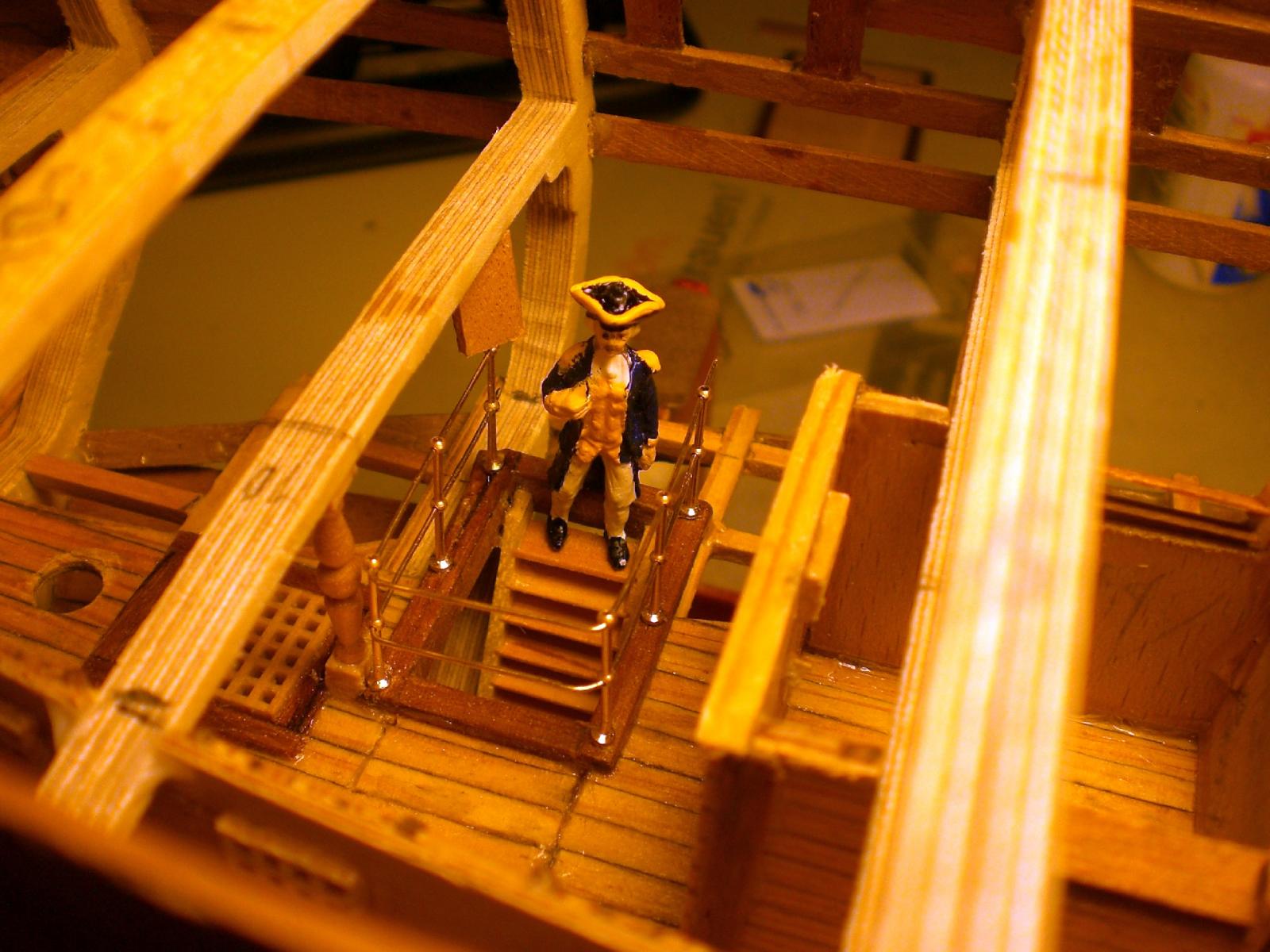
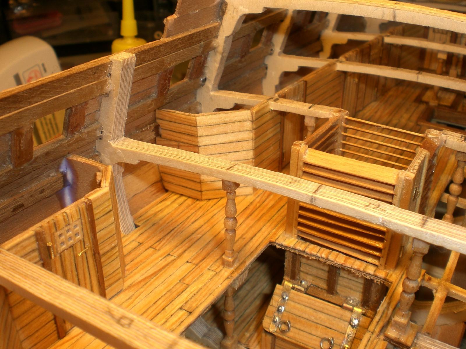
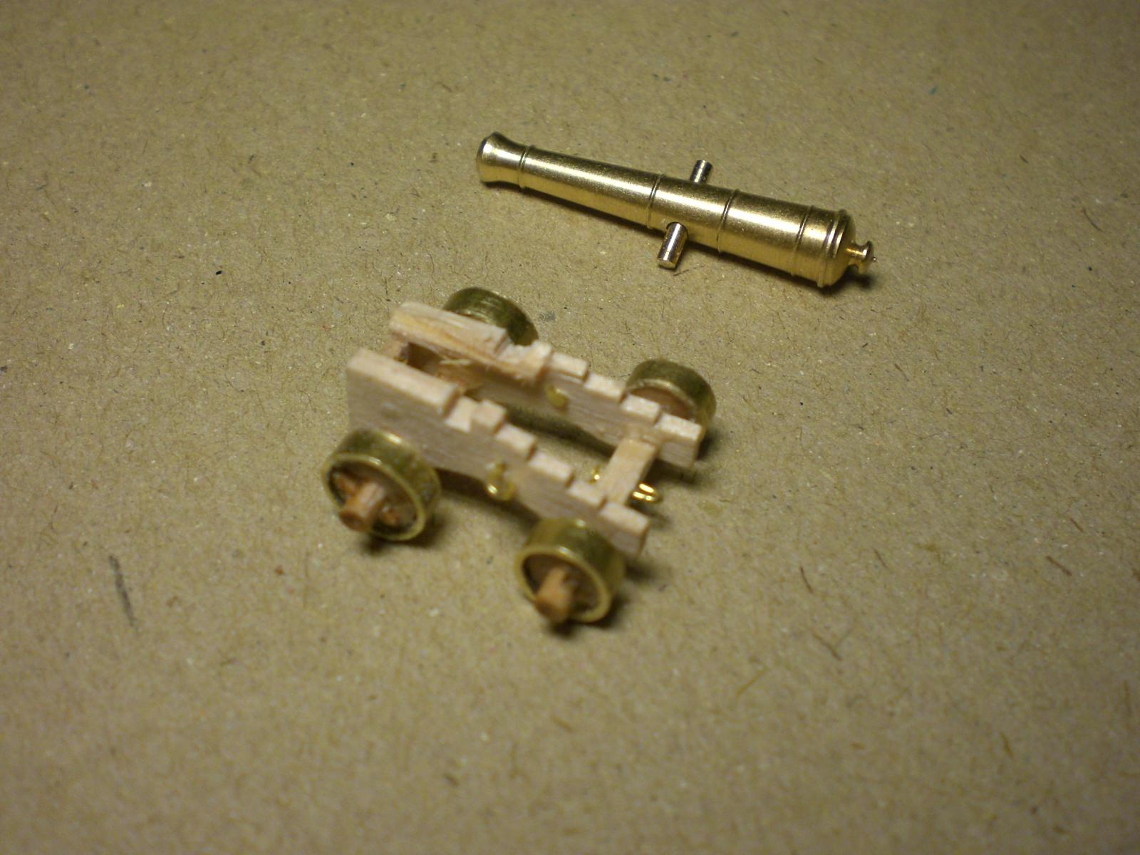
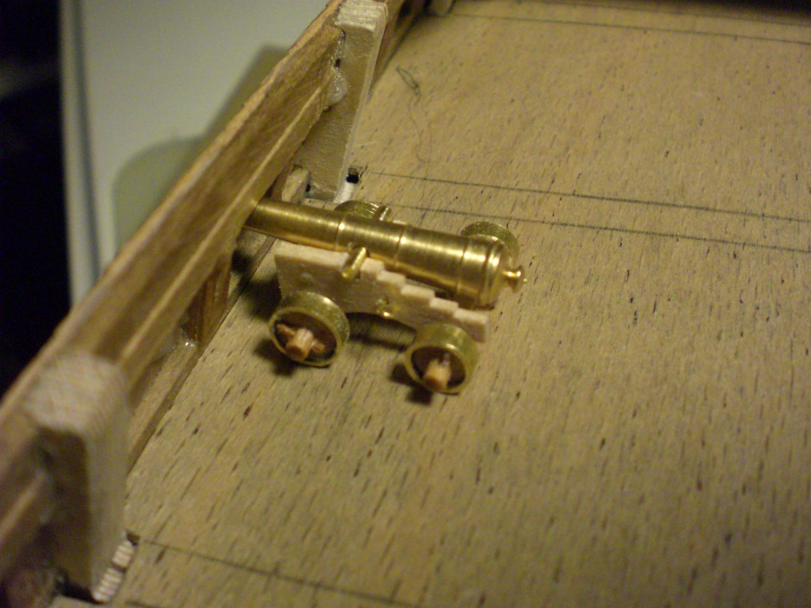
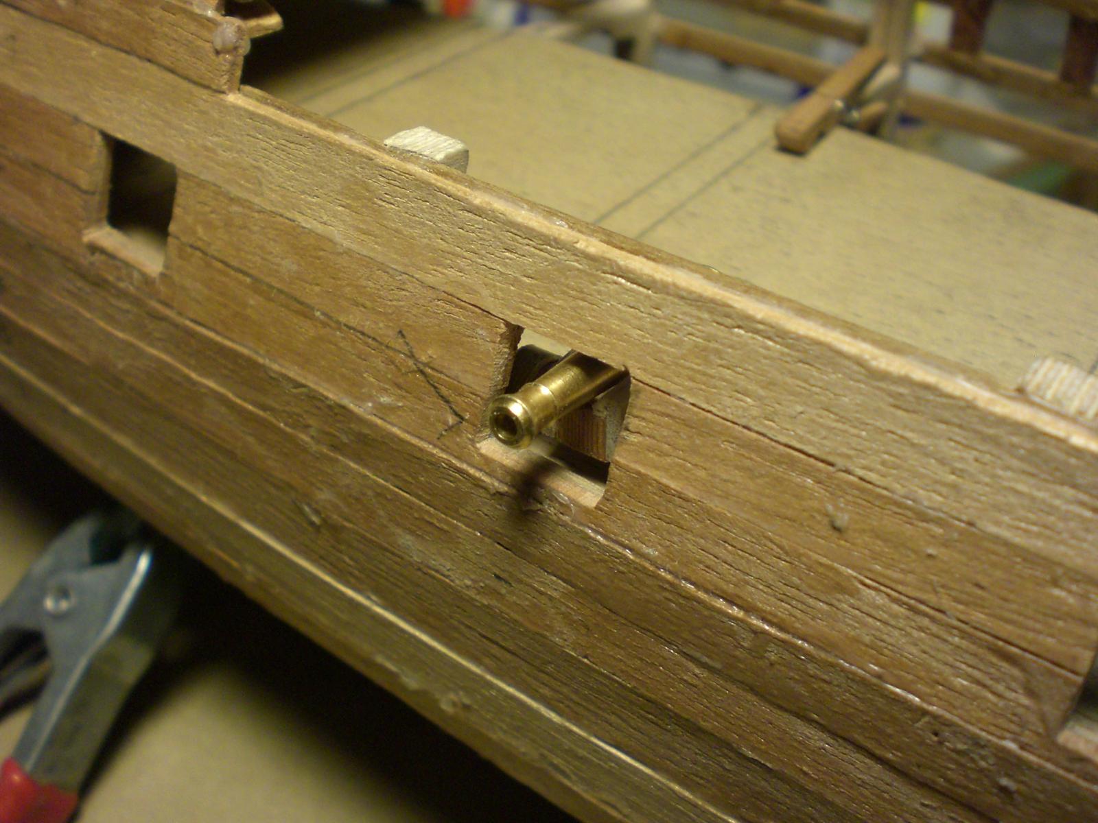
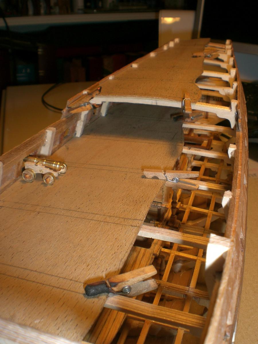
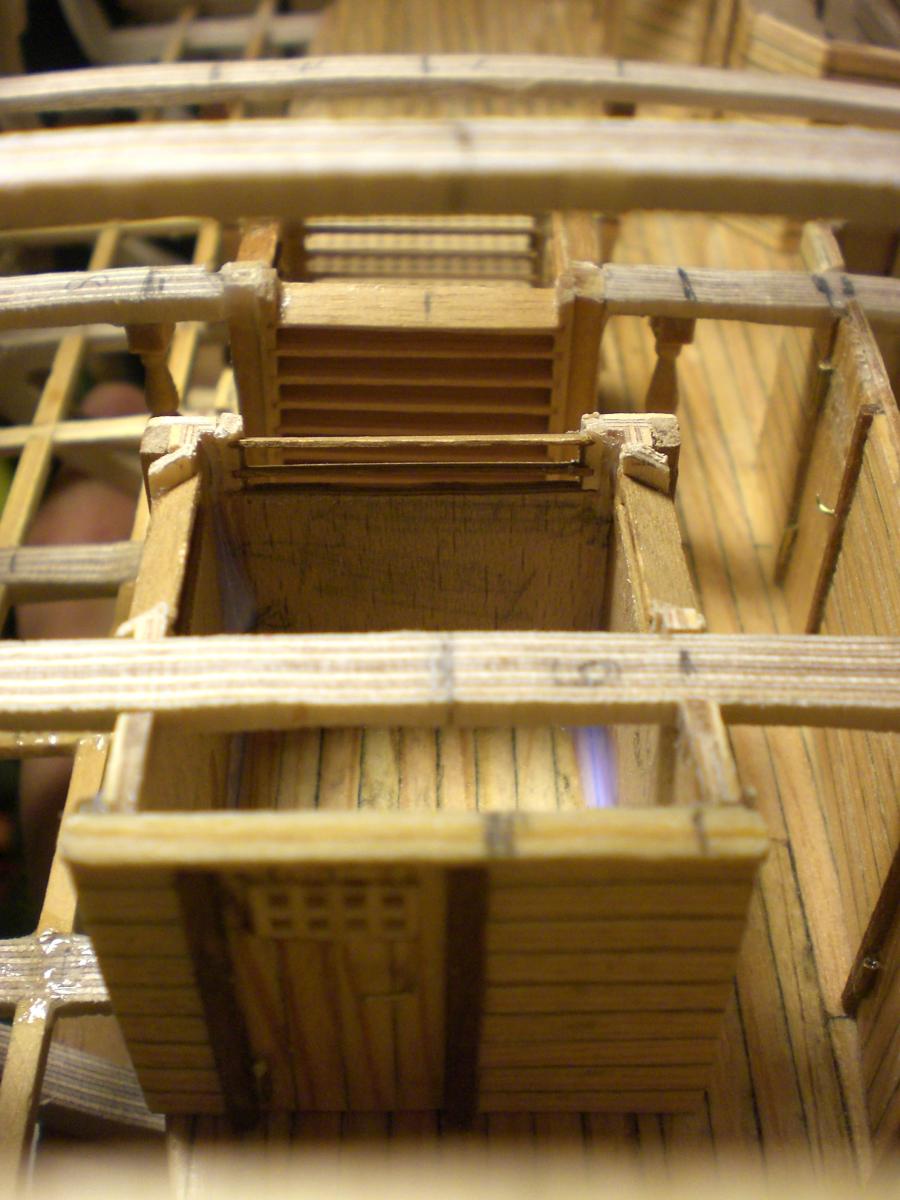
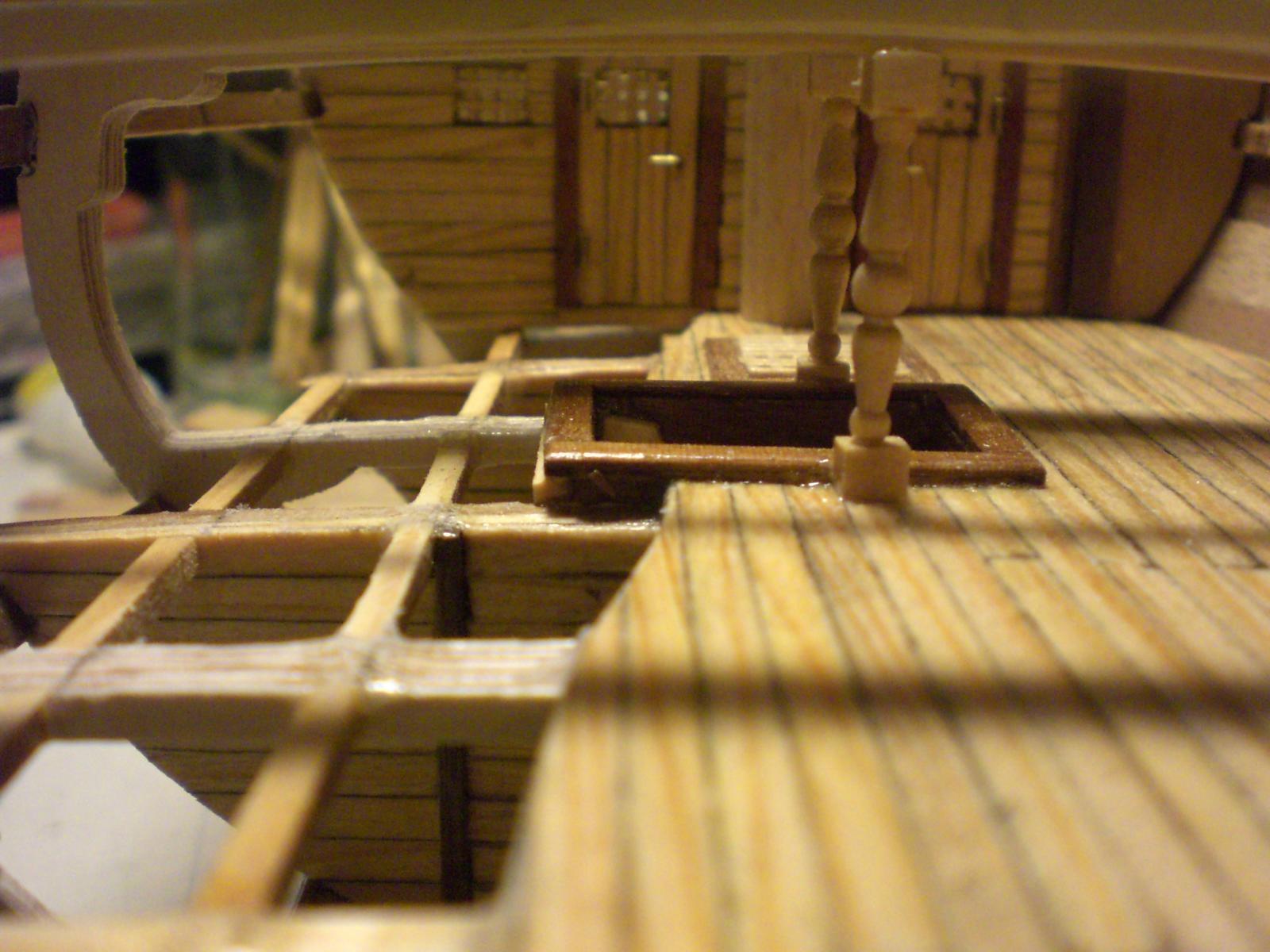
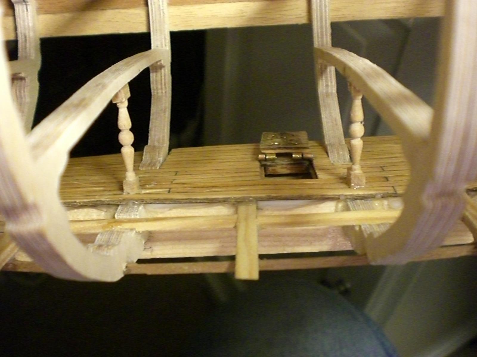
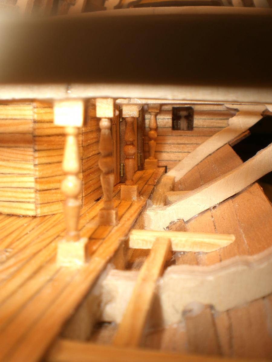
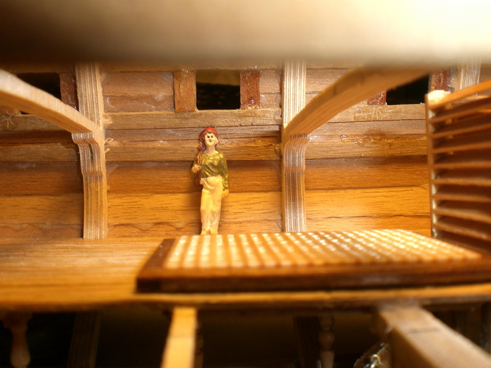
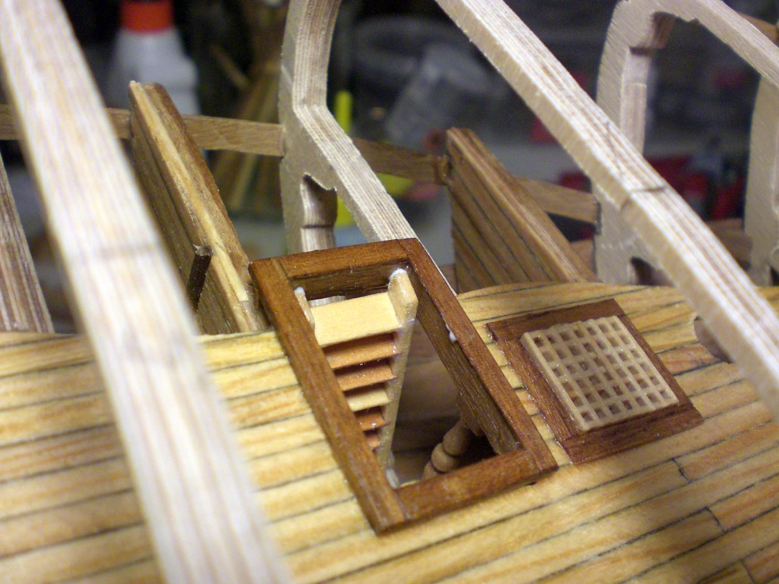
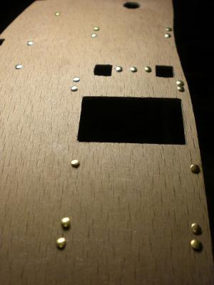
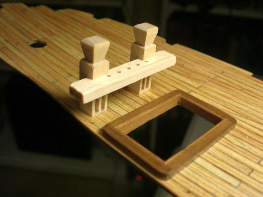
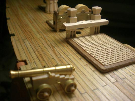
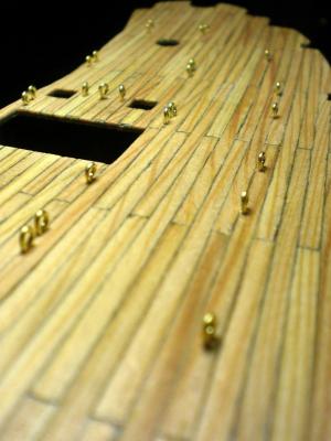
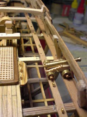
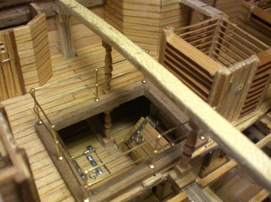
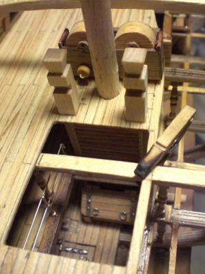
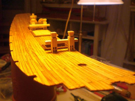
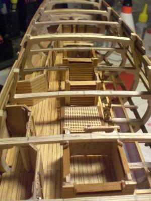
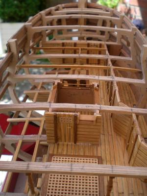
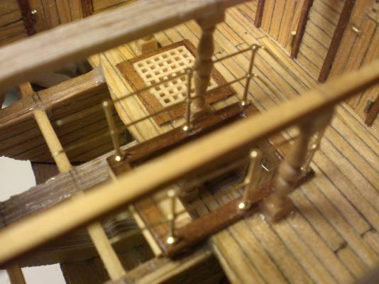
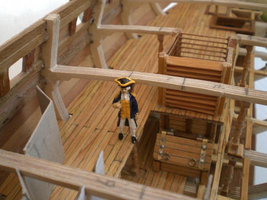
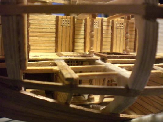
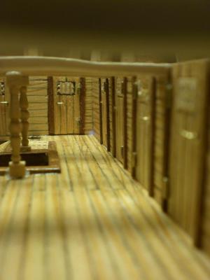
 lot 10 of my Pegasus buildlog..... doing positioning check on gundeck hatch entry of front downward staircase. Belaying pin rack from RB- Models modified with brass rollers in both Posts self explaining.... looking at both cargo and intermediate deck view through portside outcut because of no later possible Access to the eyelets above deck all such Points have to be safely countered. the brass pins I use have large enbossed flathead, are very priceworthy at Ebay, are available in different lengths and differ from 0,5mm to 0,8mm in wire Diameter, depending on where they shall be fitted. gun-carriage eylets have 0,5mm diam. whereby the gun deck and bulwark-tackles shall be of 0,8mm. Fitting goes together with inner bulwark planking later on self explaining this Status of the gundeck does not hinder the slipping in from above, due to it`s flexibility These wonderfull milled capstans (in propper scale !) are also RB models Inetnet shop product. under the grating aft of the chainpump boxes the rear staircase runs down from gundeck to intermediate deck how to Position the portside guns and their tackle when there is no deck........ port of the main hatch grating I needed an extra Little deckextention to place the appr. eyelet tacklepoints. The gun is not permanently fitted yet, only for Position check At this stage I am thinking of how doing best the Aft quarter badges in order not to ruin the beautifull etched brass parts, shall probably provide solution in the next lot
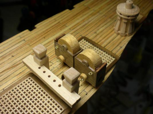


-
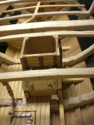
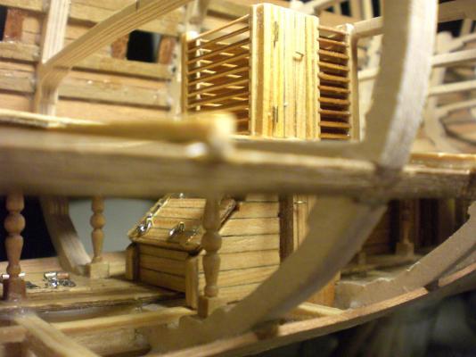
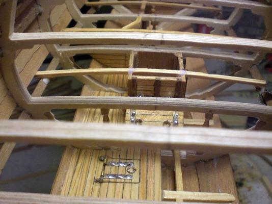
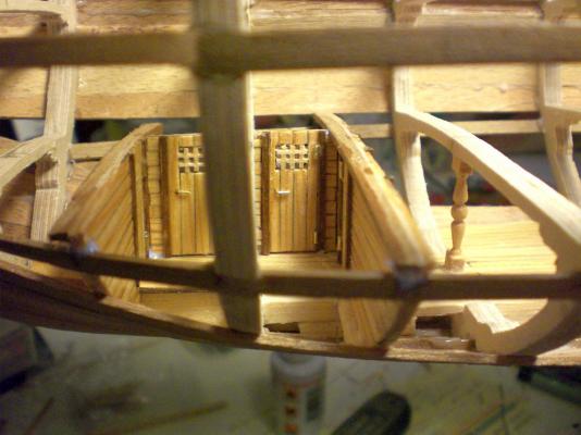
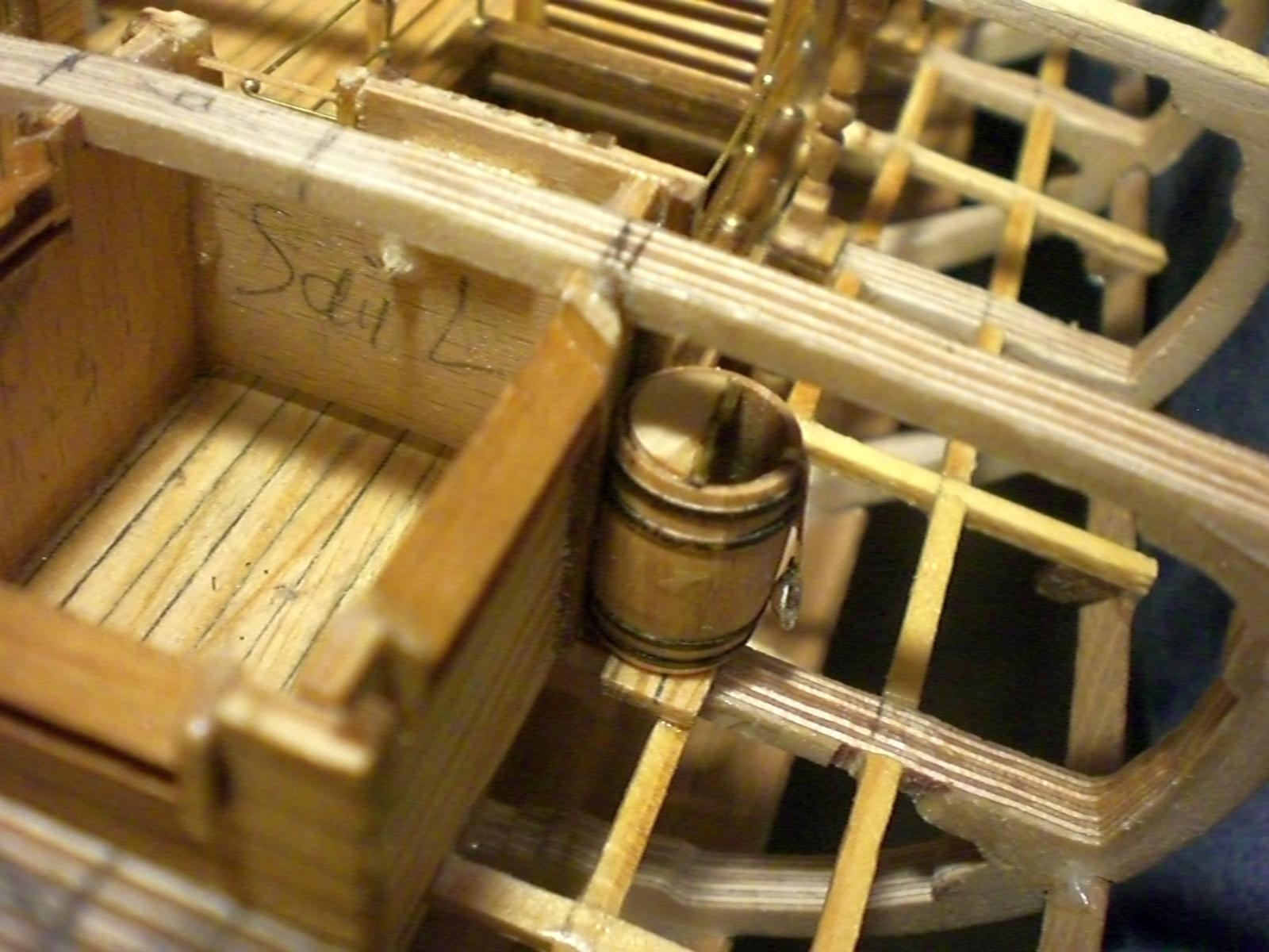
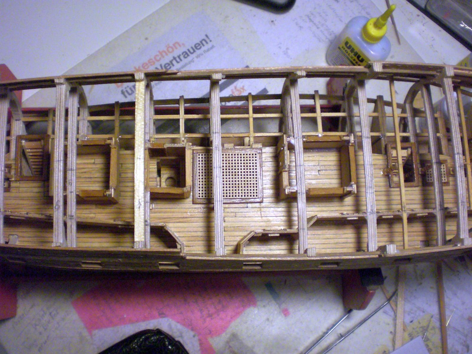
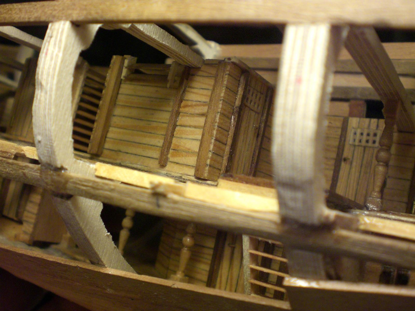
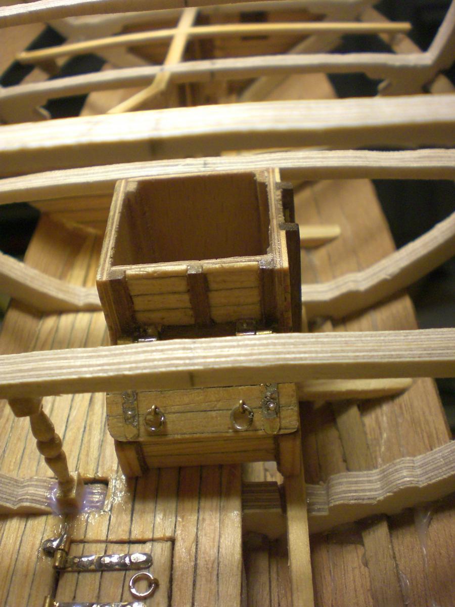
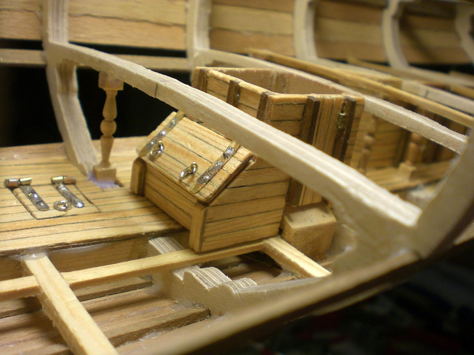
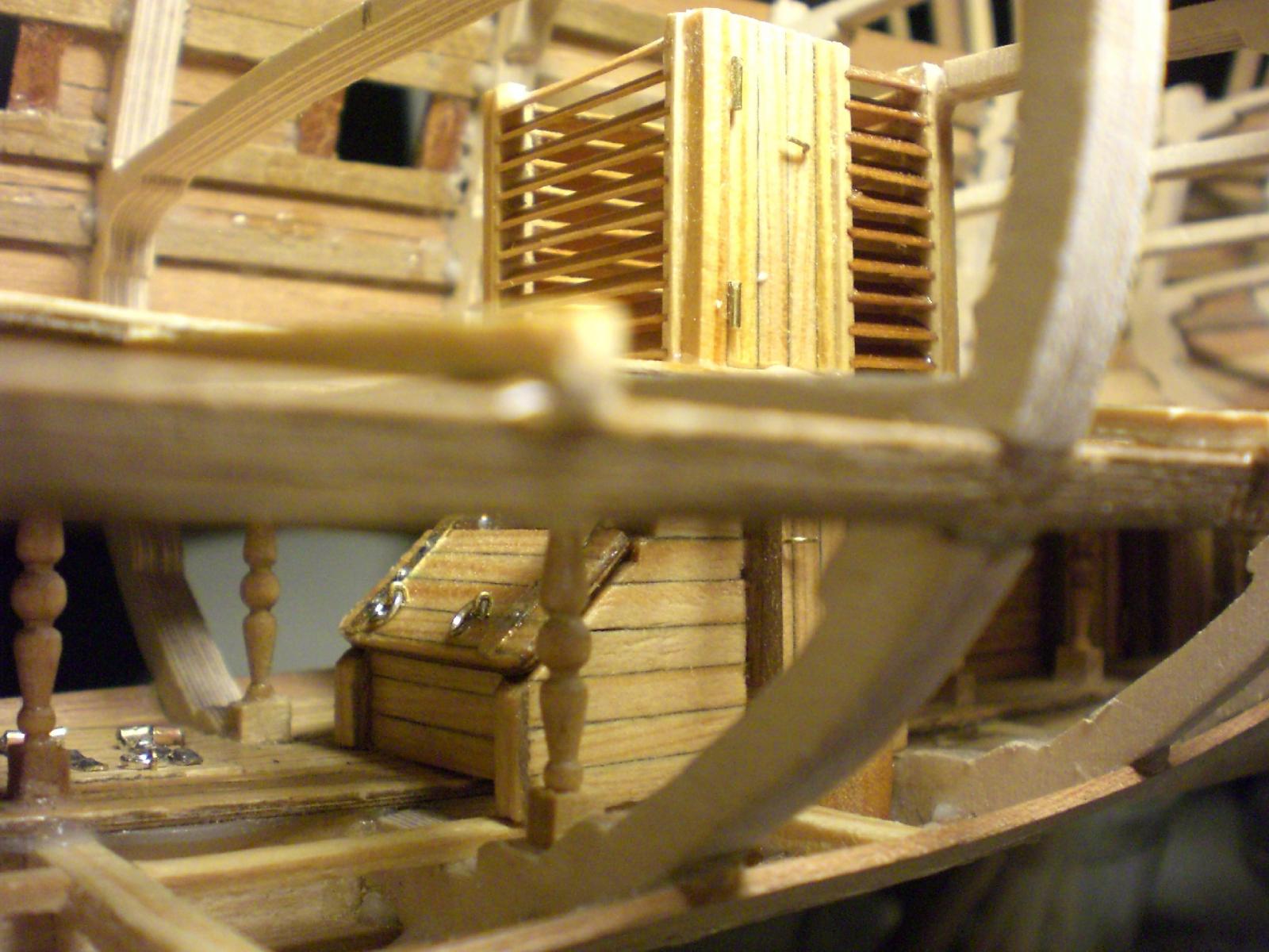
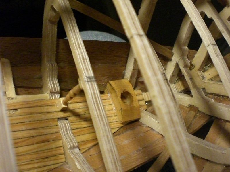
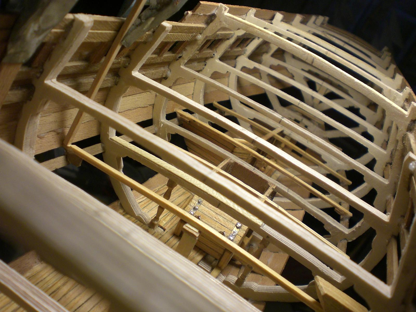
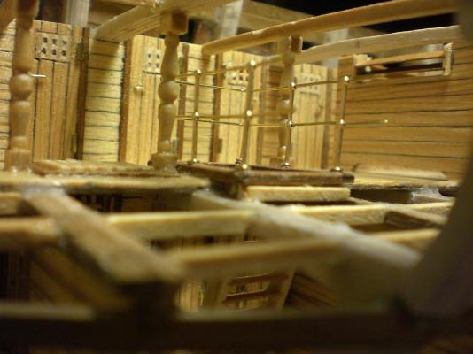
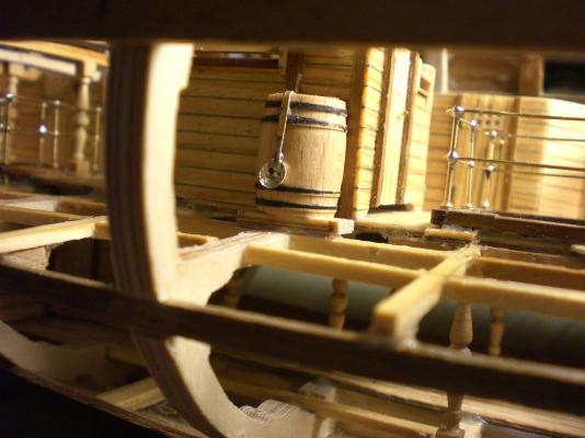
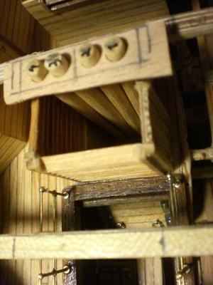
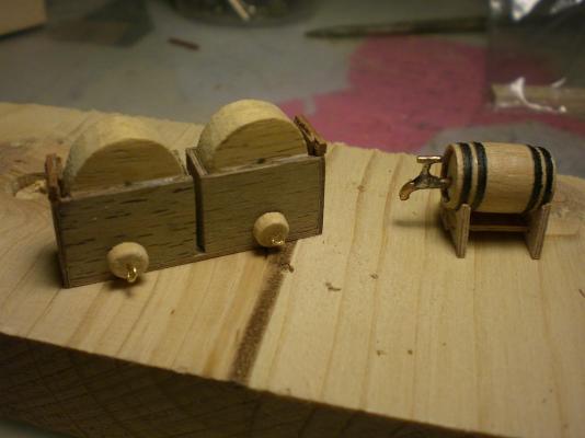
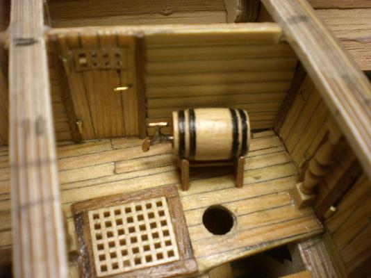
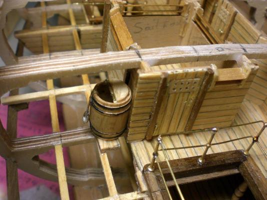
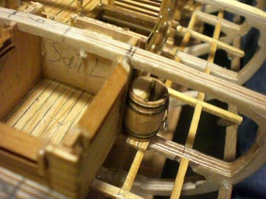
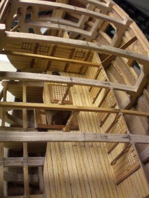
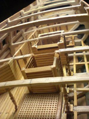
here are prepared lot 9 + 10 of my Pegasus buildlog......... front area downward staircase here the safety railing for the holdhatch in the intermediate deck is fitted. The grating of the gundeck hatch shall fit here as well the freshwater Barrel with halflid and large spoon finds it`s place on portside next to the sailroom self explaining..... upper well Containment with 4 chainpump tubes and bottom base for the pump discharge boxes Sailroom as well as pantry have Ventilation blinds fitted chainpump boxes with chainwheel covers, slide Panels at dischargeports and drainplugs at lowest Point. Also the rum-Barrel with tap is waiting for first filling the rum-Barrel finds it`s place starboard of the mizzenmast Position in the officers quarter of the intermediate deck starting with the gundeck gundeck from pine-planked 1 x 3mm strips on 0,8mm ply Basis. The deck will be slipped in from above as I described earlier in this log
-
Hi Toni, you have a fantastic model, I very much admire your skills and the results when sighting your buildlog, it`a pleasure to see this. To what degree shall you complete the intended Version in 1:48 ? Such a model would be a pride to Display ie. in the Hamburg maritime Museum. Will you be placing it on a stand. One question I have : Are all These precise cutten frame- beam filling parts, etc. povided by an extensive kit with ready cut / milled parts, or must they be taken from a plan set, and Hand cut ? I trust in both cases it must be very ambitious time intensive Task to get the detailed parts seperated logisticwise somehow well marked and well prepared for sectional assembly. An outstanding Job you are doing ! Nils
-
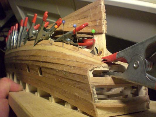
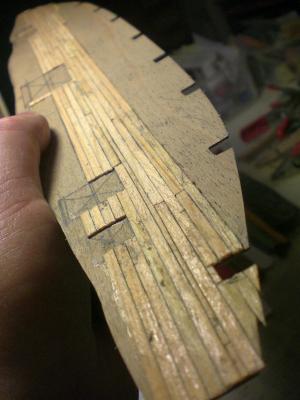
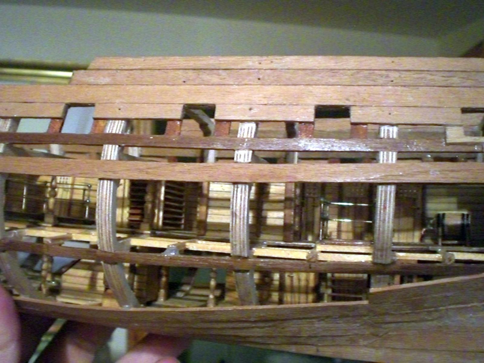
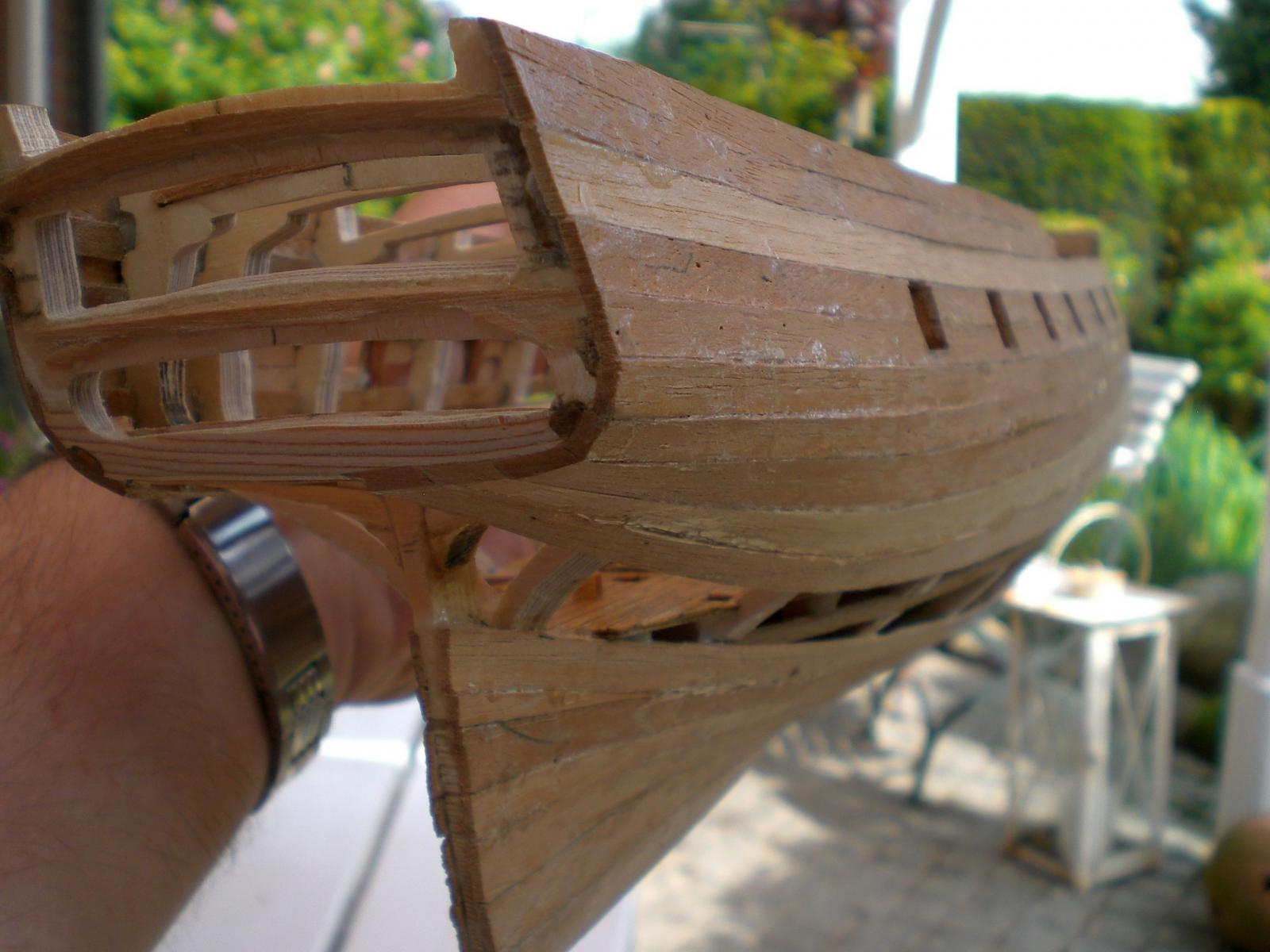
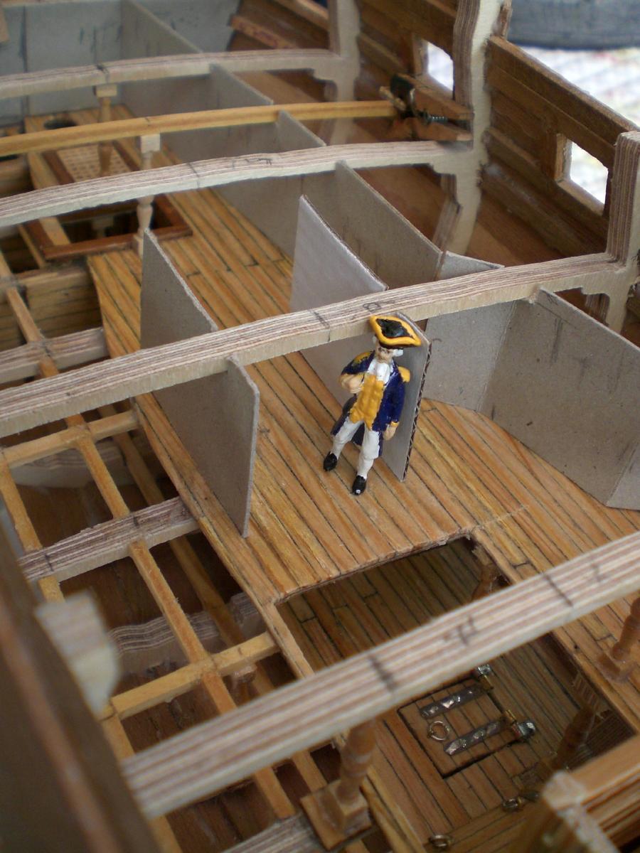
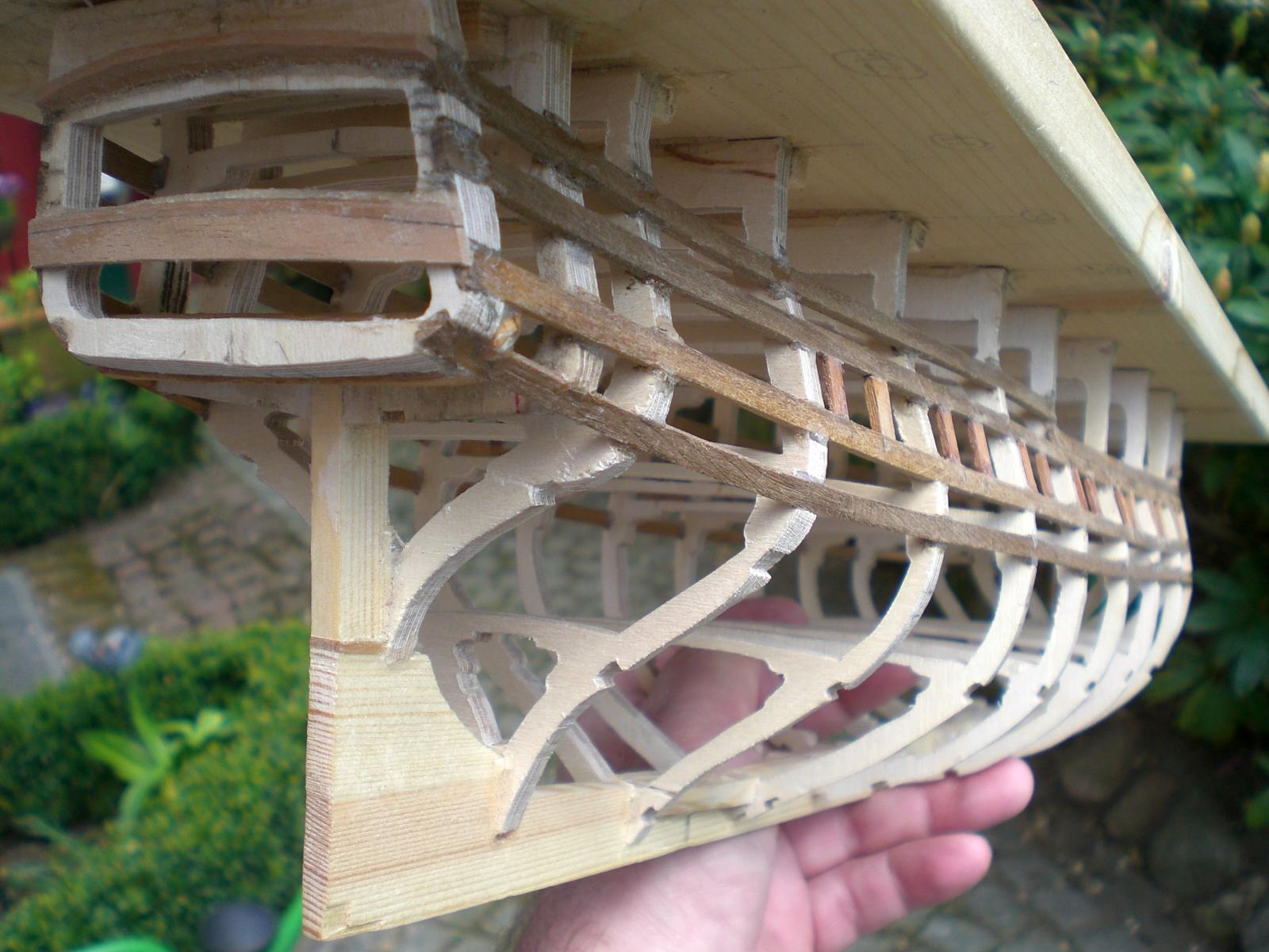
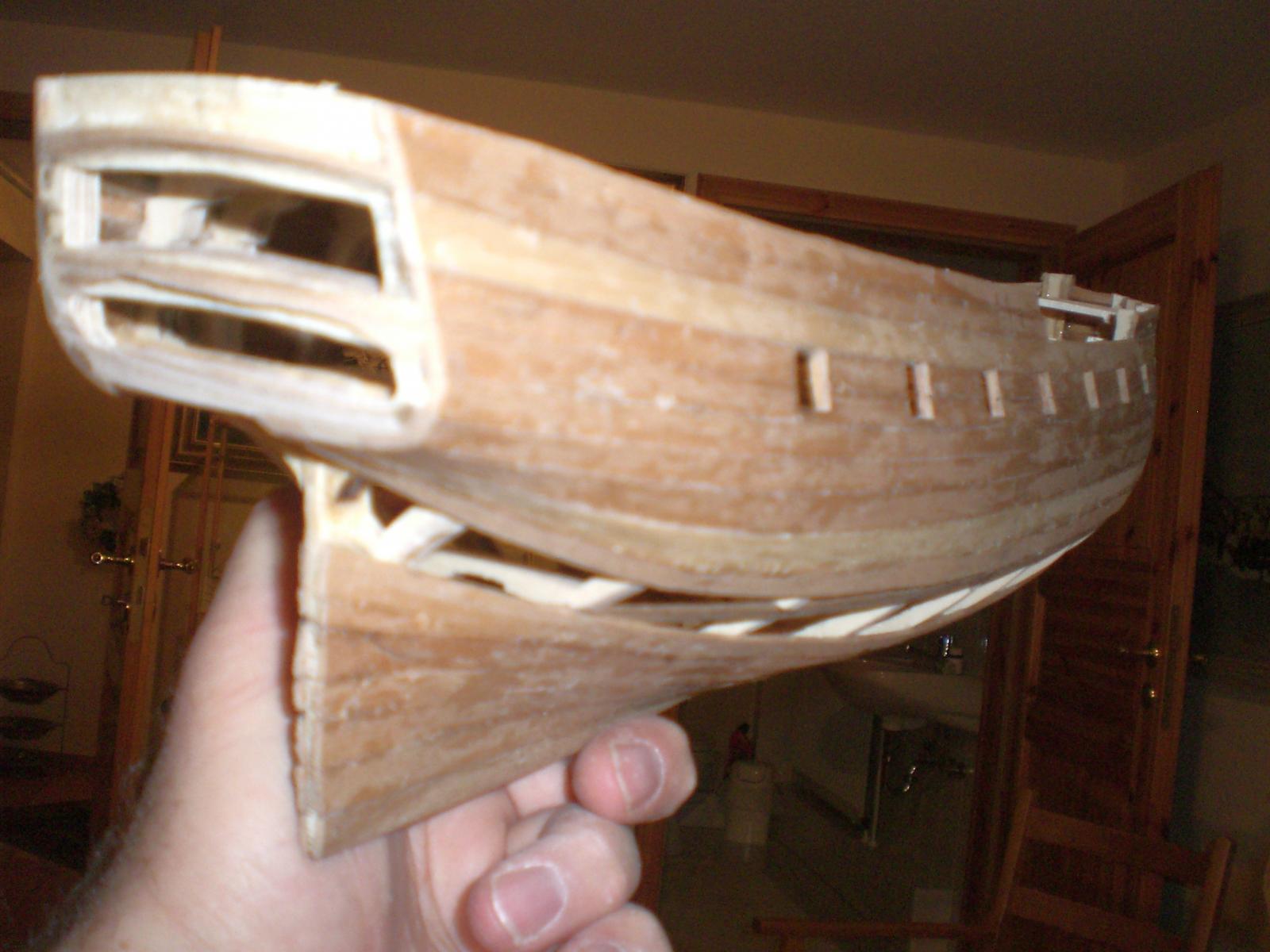
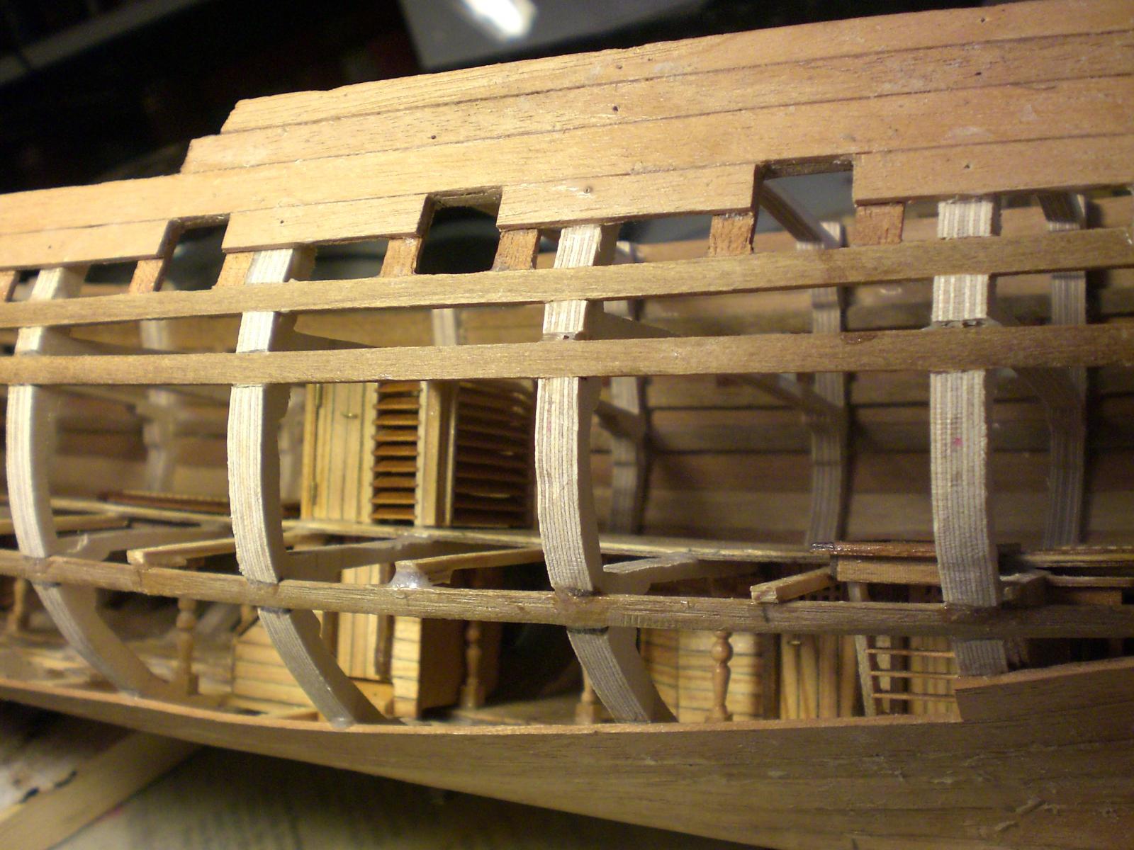
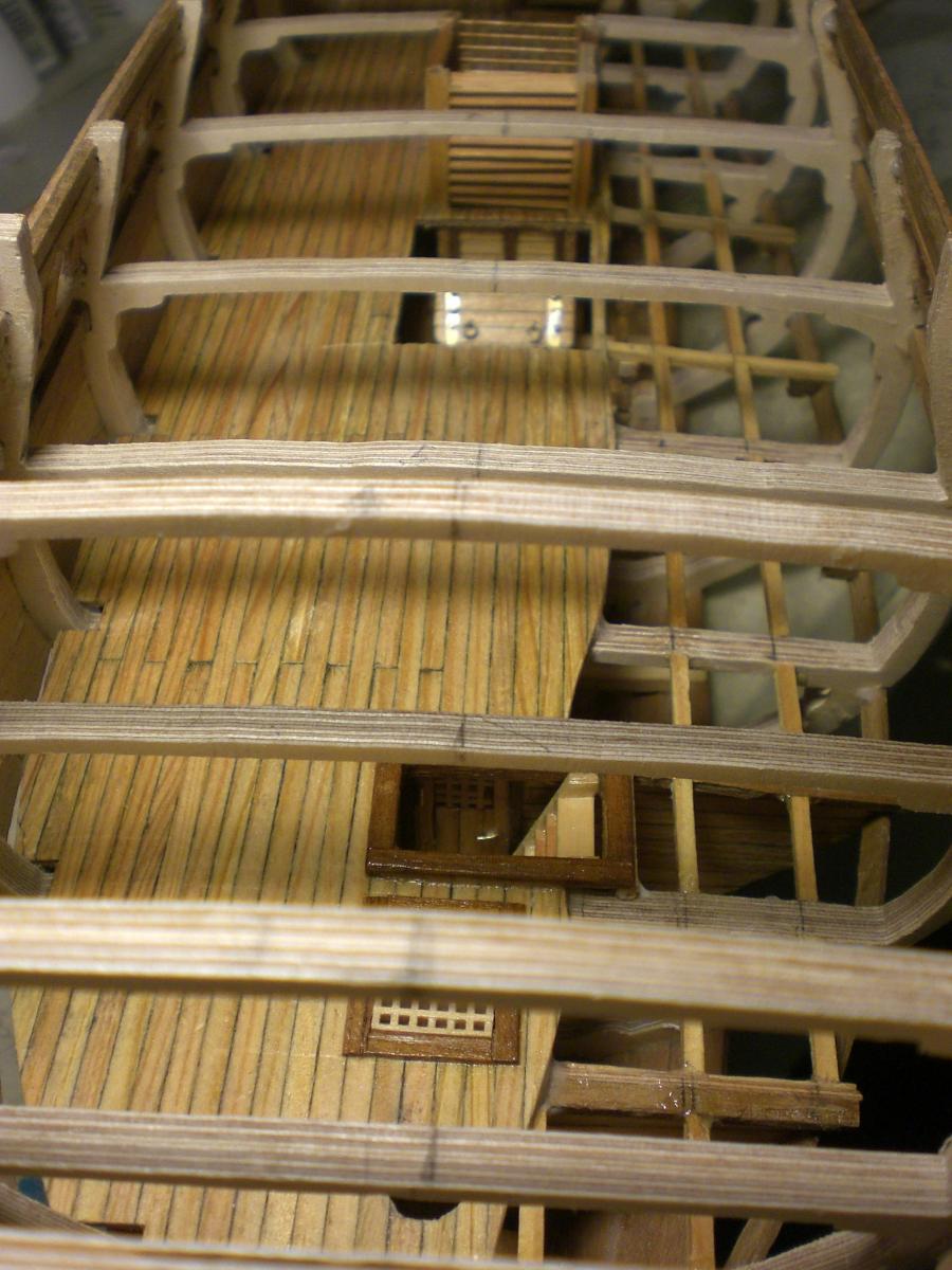
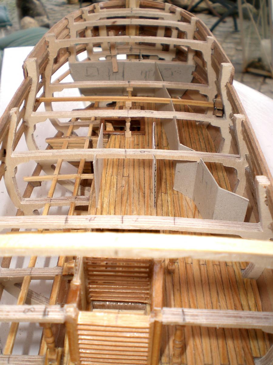
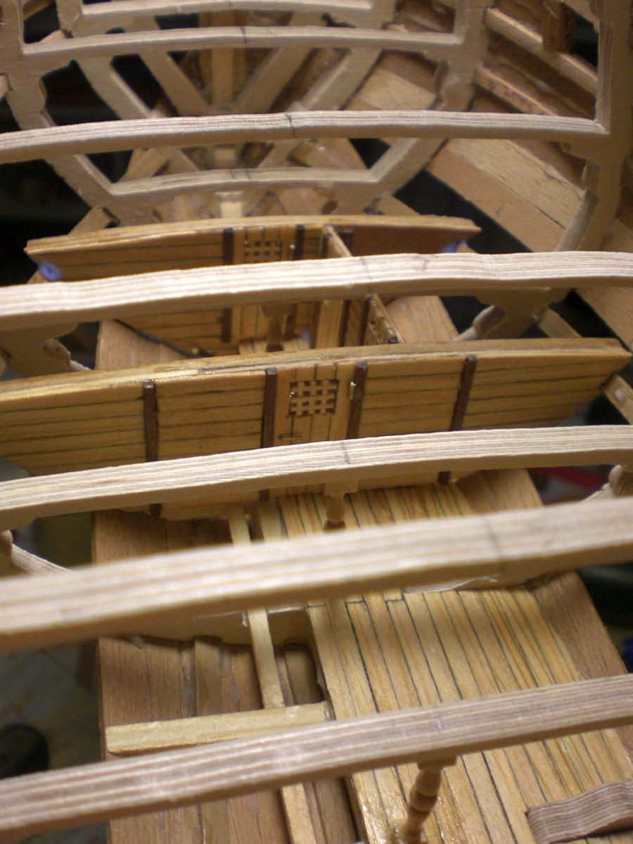
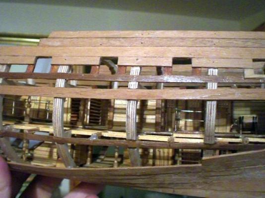
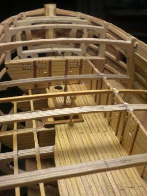
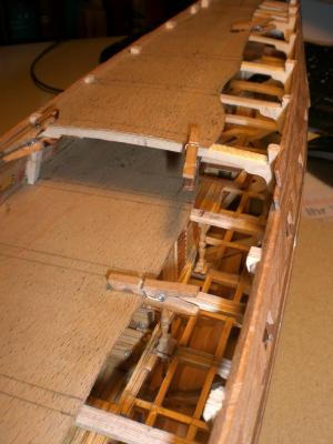
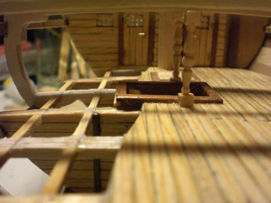
8th lot of my Pegasus buildlog...... note, the sternpost has been sanded down to half its width Prior to planking, so final width after planking and sanding is at average 4,5mm`, trust that the rudder shall later on be of this thicknness at it`s widest thickness the 3 mm width planking of deck and walls are identical (3mm x 64=192mm in reality, seems realistic, being about 1,5 width of the sailors shoes). By the way, all Deck and wall planking edges are charcoaled by means of a soft pencil. This gives the tarline effect regarless to thickness even after sanding allthough many wooden structural parts, the hull is of remarkable low weight and still stiff and rigid selfexplaining view view aftwards, now in foreground the sailroom has been added, behind are grating on hold hatch, Upper well housing and pantry. On starboard side traffic corridors, sailorcrew and marinesoldiers accomodations. Between upper well and pantry (here not visable) a staircase goes down to the cargo floor. This may be the main trafficway for fast Access from the filling room (under the waterline) via aft staircase in the intermediate deck up to the gundeck same Features with view from top, aft birds view intermediate deck nearly complete....... the sailroom space seems to be limited, but could not be increased due to spaces between surrounding facilities interior staircases fitted with railings to increase safety in battle and when ship is rolling again intermediate naval inspection..., the officer means that in a far future a day will come, where even the stairs will have to equiped with handrails at this Moment I have`nt made up my mind yet if I should apply coppering, White "Antifouling Appeal" that allows the plank and grain structure to be recognised, or nothing of both. Would appreciate any fellow builders coments on this....


-
Danny I was so much surprized and amazed from what I saw when I read through your buildlog. I find it breathtaking ! When I was a 8 year old child, a brother of one of my pals in Capetown once showed me a 17th or 18th. century and about 1m Long shipmodel he was working on. I could not believe that someone could be so much knowledgable of the techniqes and skills applied in those "ancient" days and being capable to adopt this into a scaled model. All the workmanship, the Features, the particular Wood connections looked like what you are doing. Because all The following years to date I never came across something alike again, except from Special models in maritime Museums etc. I would love to see what your model Looks like completely rigged, with or without sails. Are you perhaps intending to build an admiralty type demonstrator model ? This also applies to the other high skilled modellists introduced in this Forum as well, their babies basing on TFFM plans and in scale 1:48 eg, Toni`s Atalanta I read through just before. At the time I picked the Plan of the Pegasus because I loved this ship classification for my own Project, I was not aware of what is being built in several model shipyards at this time. I have myself amoungst others,finalized Tallship models like the threemastbarque "Gorch Fock" in Version of the 60ties and the flying P-liner fourmastbarque "Pamir" in the Version she foundered in 1957 Nils
-
Aldo the keellaying was in April this year, we now are nearly 4 months later I asume that would adequate for the build Status provided one has the time to do so. But I am retired from work and took up ship modeling again. The reason it Looks like speedy session Basis on the fact that I started issuing buildlog Posts out of my photo documentation just a few days ago. Nils
-
Hi Juergen it`really a great pleasure to see this Kind of skill Level and results being kept up and practiced in our newdays time of plastic and kits. I find myself also it is the individual Motivation, combined with the idias pregnant in onès mind and the neverending drive to tackle and solve difficult sequences. This Forum is a great place to Support this attitude. Keep going so well Nils
-
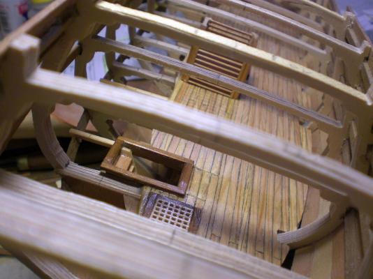
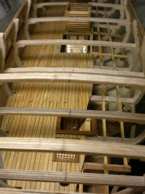
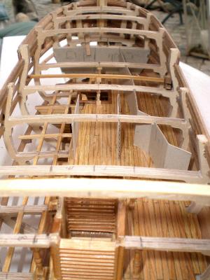
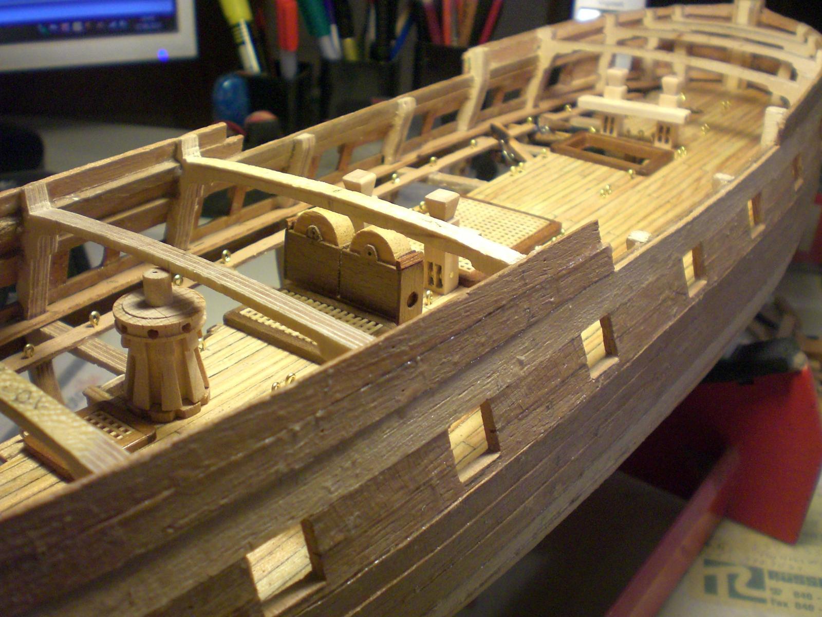
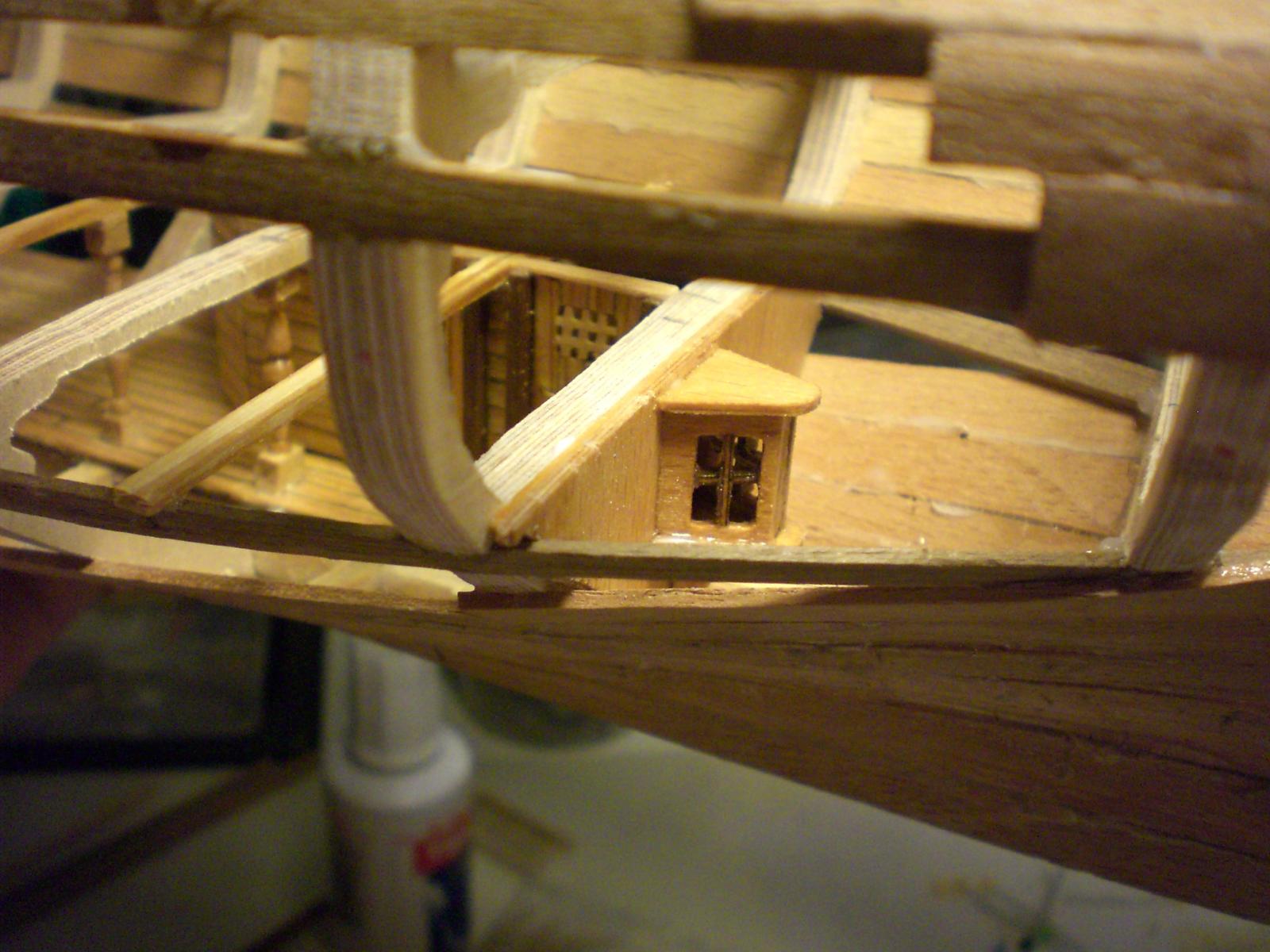
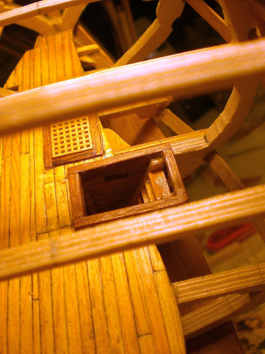
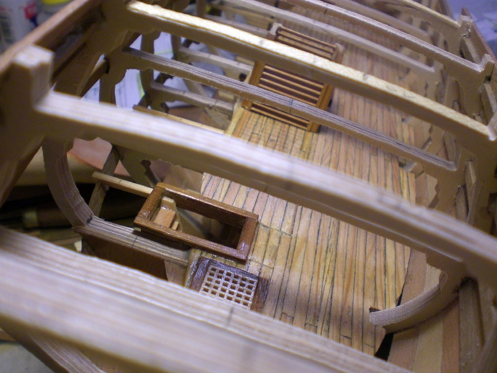
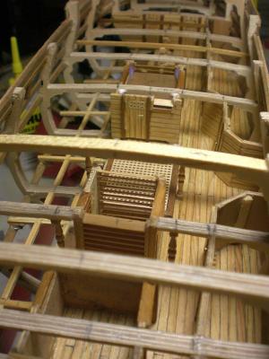
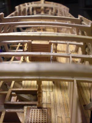
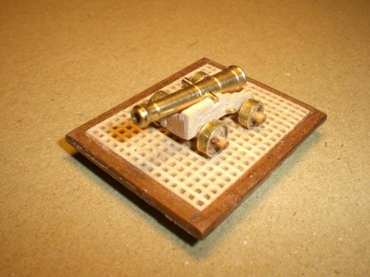
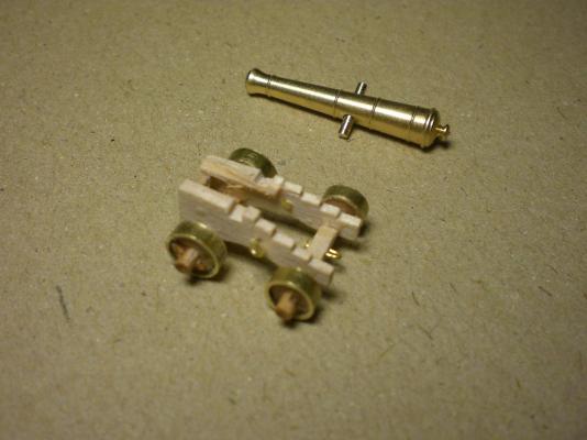
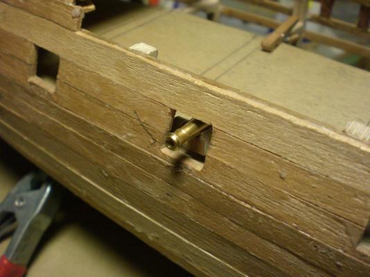
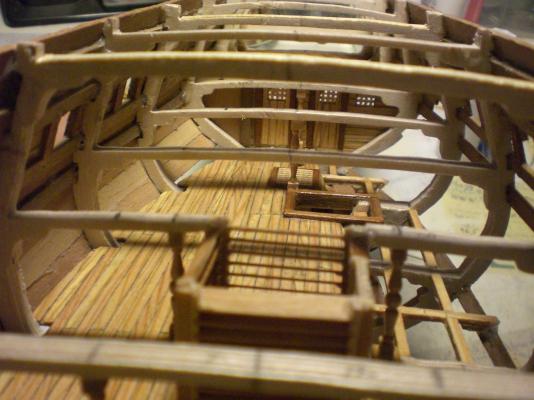
Section 7 of my Pegasus build-log...... here it can be seen that the Access when working from above is still reatively easy, even in scale 1:64 this is the first sample 6 pounder I put roughly together to check dimentions, positions. The best suitable gunbarrels and carriages I found at RB-Models Webshop. They provide even Little kits, every modellist shall modify anyhow..... here I fitted splints into the axises and brass hoops around the wheels, further improvement pending the hight of gunbarrel passing through gunport hatch is OK straight away, the Barrels are 32 mm long (6 pounders) at this stage ´m not quite sure if I should apply chemical blackening to the brass parts from abone sight is given (portside) right down to keel and cargodeck floor The portside gun supportbeam-rails have not been fitted Jet looking aftwards we find the pantry established rear of the upper well Containment, in the foreground is a removable grating over the hold hatch in the intermediate deck. The opening shall be secured by a brass railing and left open later on looking into the pantry room from above this also gives an Impression of the single layer planking edge (appr. 1,3mm after sanding the outside


-
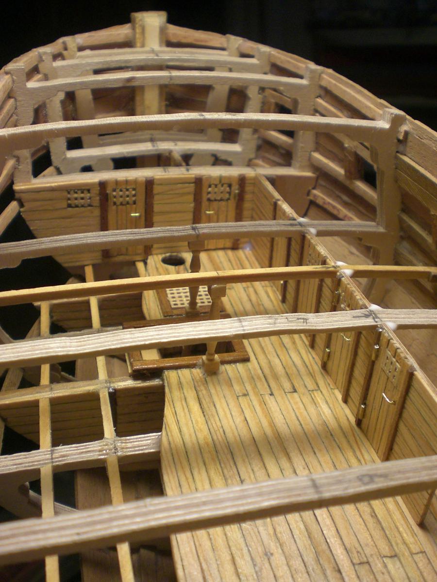
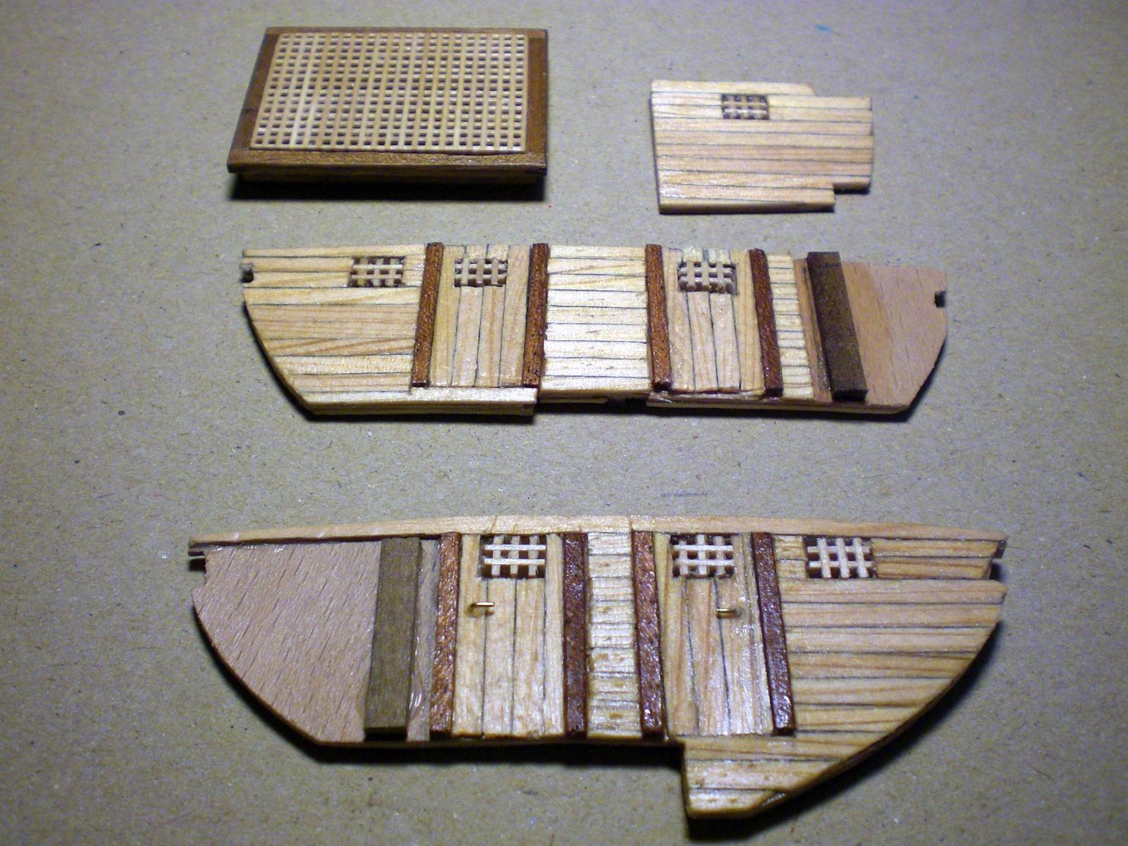
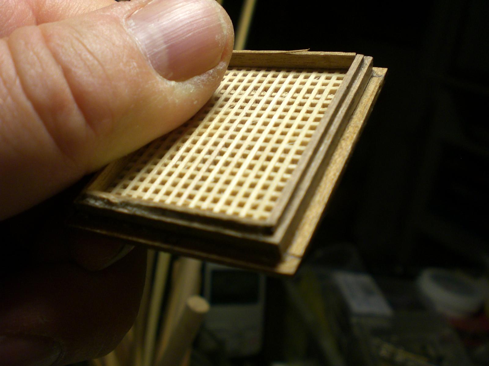
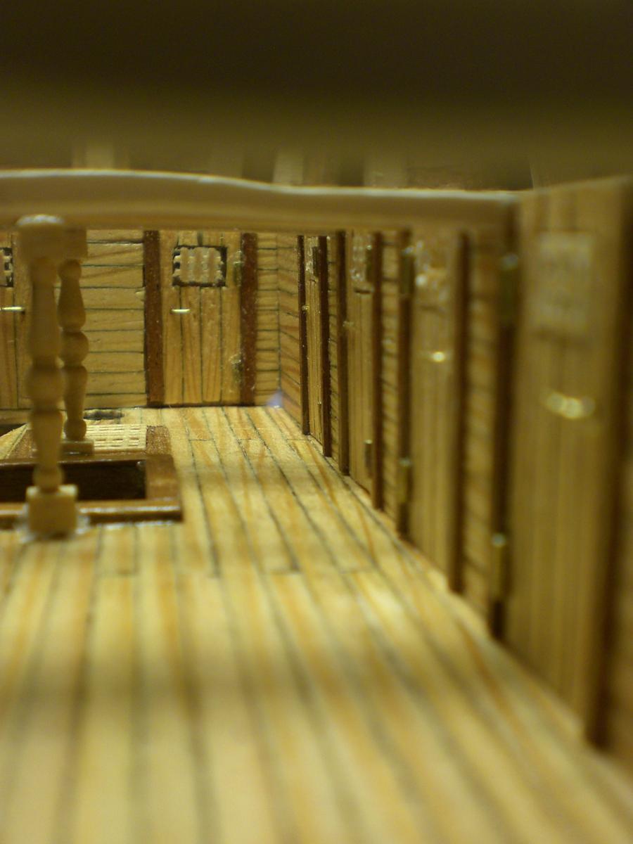
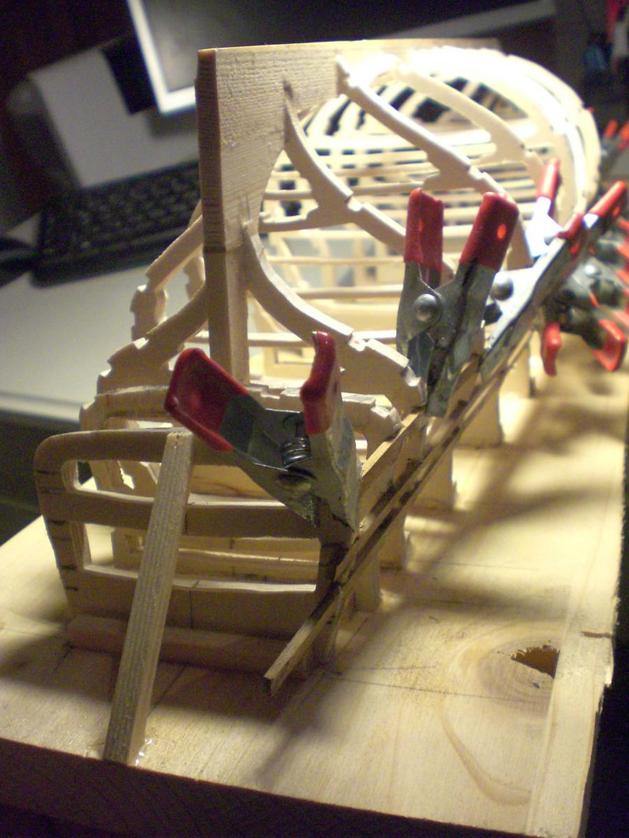
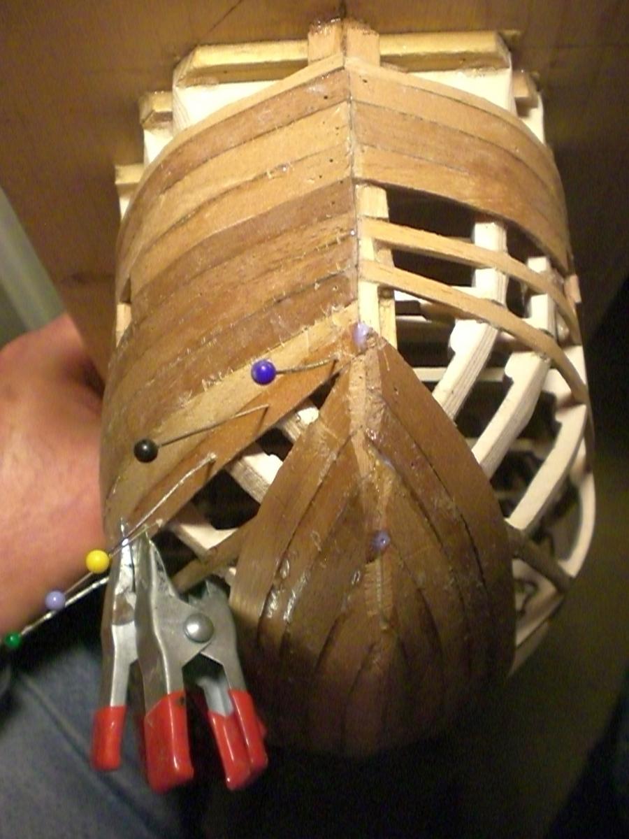
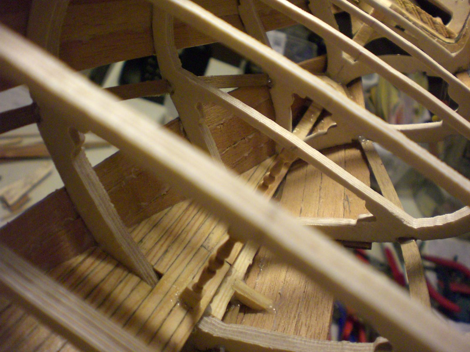
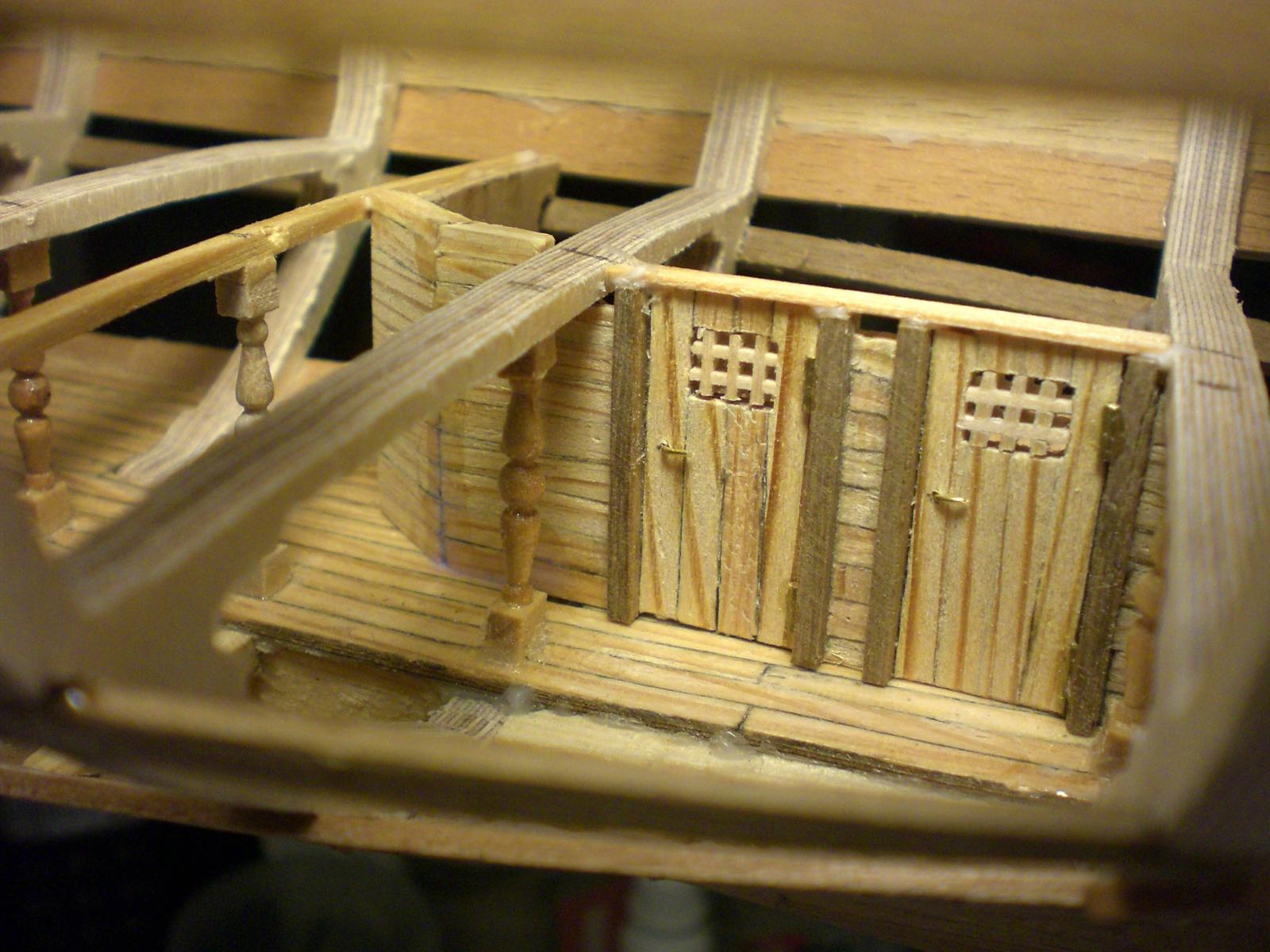
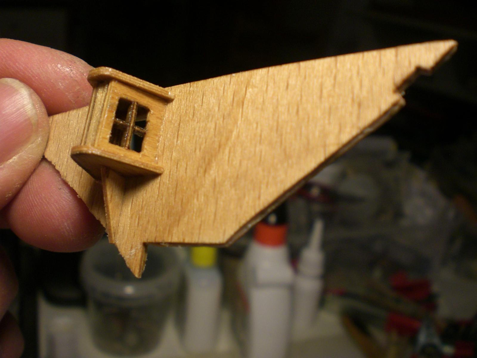
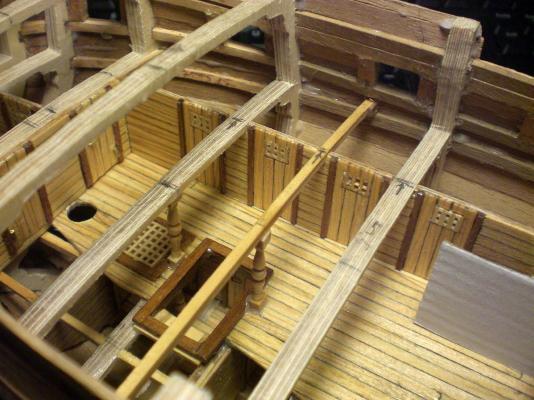
following Mark`s advice here are the continuing sections 6 and 7 of my Pegasus build-log here at the sternplate there are horizontal openings, this is where I find Counter Position for placing the clamps during planking. Also when the decks are slipped in through the Frames from above, the deck can be pushed out rear to appr. 1/3 of ist length til the front part flushes into the correct Level. Then push back the deck bowwards The naval inspector angerly does not approve cardboard interior..... several bukheads have to be planked from both sides and equiped with vent openings in the 18 century type doors the gratings are prefixed with Framework and then fitted into the appr. deck positions. Tight fit, so they need not permanently be glued in I Chose for interior the natural Woods pine for decks and walls, mahagony for frames, buche(german Name)for pillars, boxwood for stairs around the upper well area have to be carefull not to dammage the venetian Lamellen of the Containment it must have been about 25 doors fixed in the total of the visual walls in corridors and side cabin rooms. Note that the portside interior has been left away to enable sight from above and exterior one of the front bulkheads ( from the cargo deck floor to the intermediate deck above I know this Looks a Little bit like Finnish Sauna, but it`s not too fancy, so the 18th century in Crew quarters sends greetings, and the Budget of the admiralty is running low, because most of it has been spent on the five swan class vessels Prior to this build


-
Mark many thanks for this good advice, I shall follow your suggest straight away when posting the 6th + 7th lot of my build-log. It is also nice to know there is an extra helping Moderator`s eye open ready to give assistance when necessary and to keep the log at smooth run. I had to look up the word "interspersed" and now learnt something to my vocabluary. Pls. excuse my english and perhaps the spelling, if it does not allways hit the nail in the Center, but I hope that to date my build-log was understandable for all that are following it. Nils
-
Hi Aldo, so you´re´also working on the "Pegasus" but from the Amati kit. I found this quite expensive and therefor started with the plan the etched parts, the nice Little resin namegiving gallion figure. Purchasing wood, paints, glues, tools, etc, there also sums up quite a lot for me as well. Usually I do not build from kits, but since I came across this wonderfull Forum and having a good built model in mind that bares all my intended specialities, I found so many insperations from the fellow modelers build-logs in the Forum, so I got started in April this year. Builders that prefer to stick to the kit may find some Features strange, but that is the spice in the soup isnt it ? My building -log is nearly being edited and updated daily. How far did you get to date Nils
-
Hi Kevin, you`ll see later on in the build log, that the Position of the stringers follow the deck line Levels ( appr 3mm lower), next to giving the hull rigid stiffness they provide laying on of additional Support beams under the decks. The angles at bow create no Problems at all. Nils
-
Hi Mark, no, not in this case, remember the preplanked decks are basicly from 0,8mm ply, flexable and only appr. 3/4 the width, so they can be sliped in from above, (even the Long gundeck !). You shall see later on in the build log. also on the planked starboard side I left away 3 Planks on decklevel until the decks is fitted and permanently fixed. Works very well. Nils
-
Hi Bob, your advise is highly appreciated, I gues we got it now, many thanks... I´ll try with the next bunch of issues Nils
-
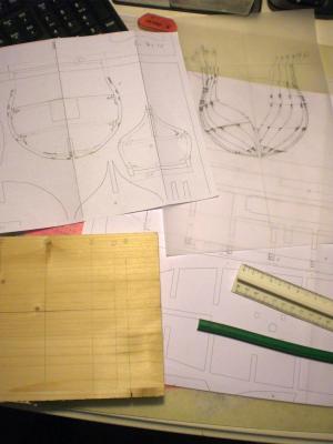
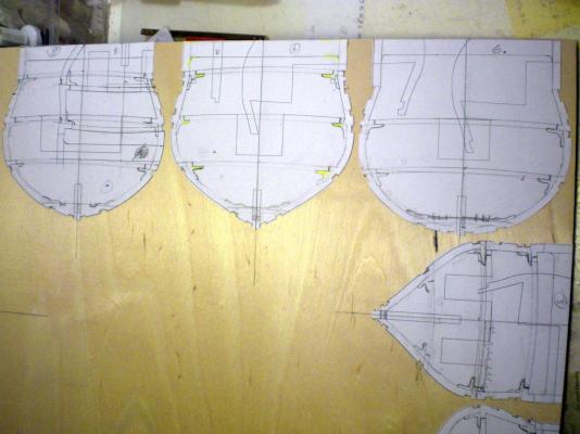
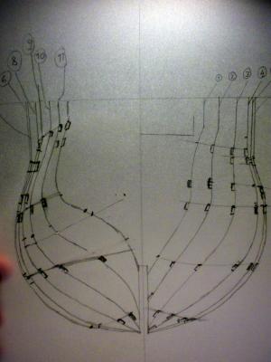
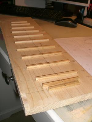
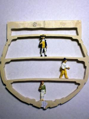
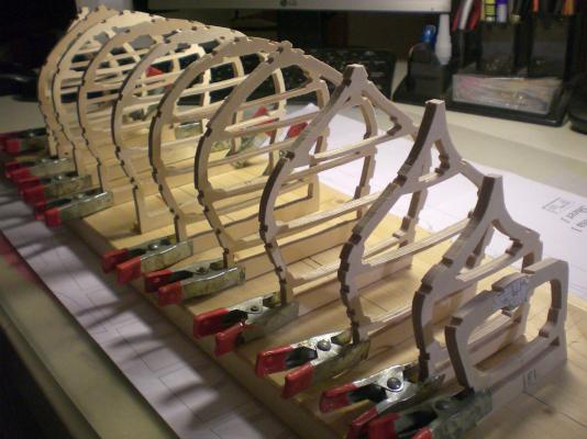
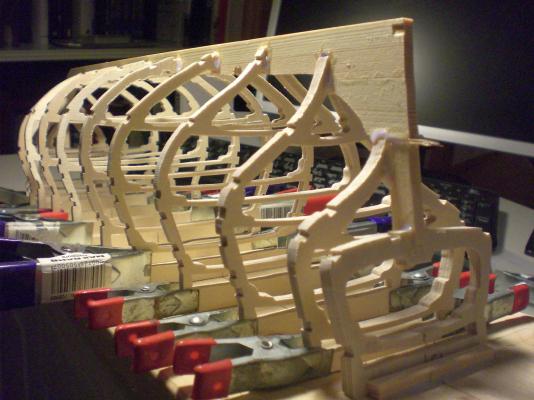
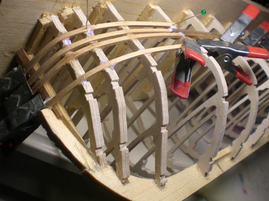
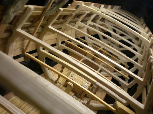
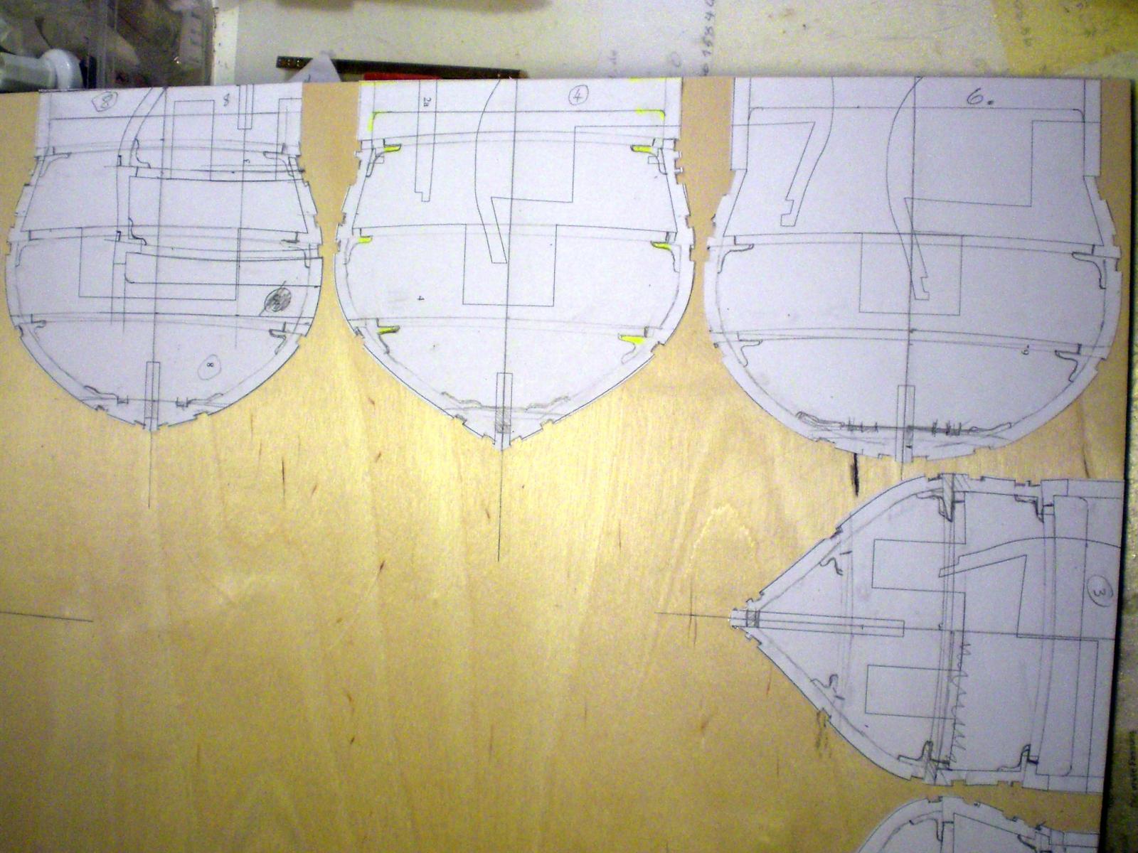
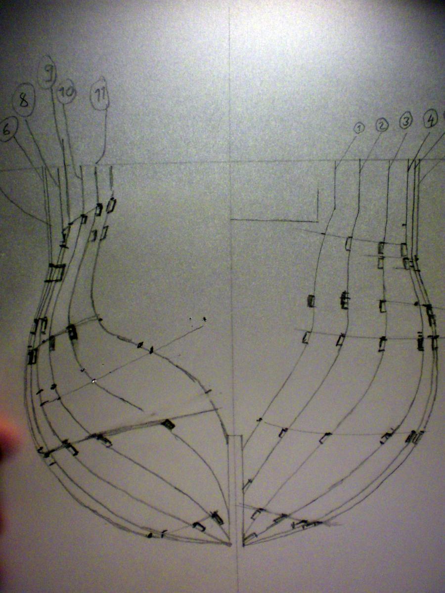
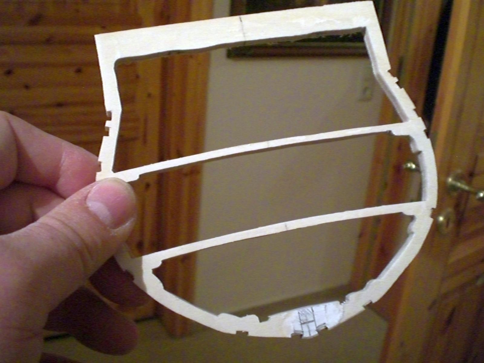
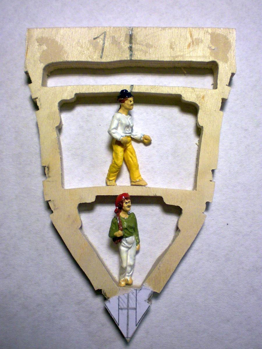
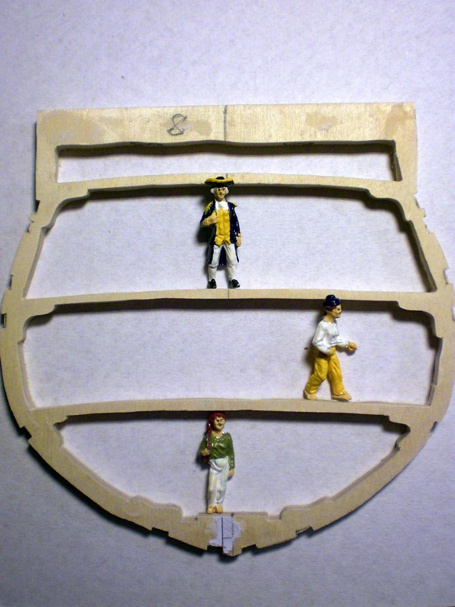
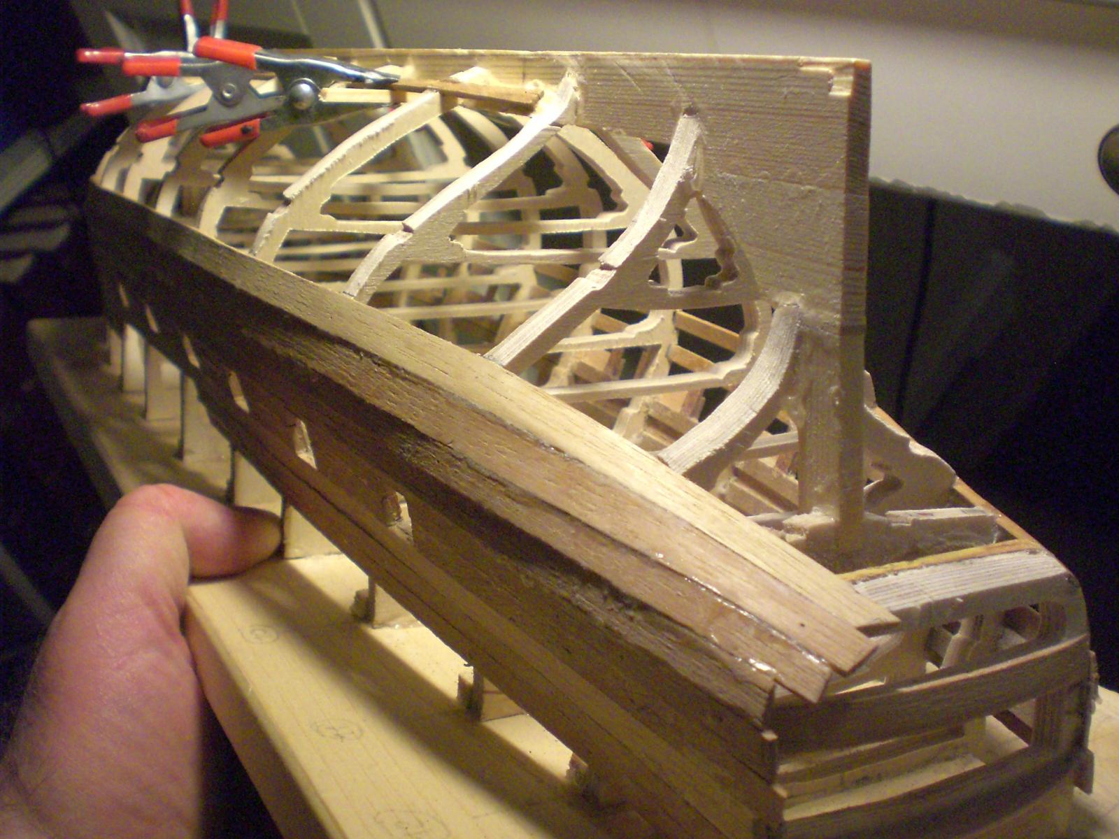
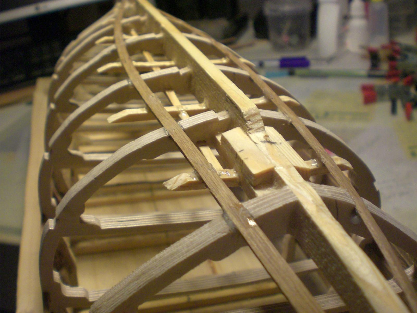
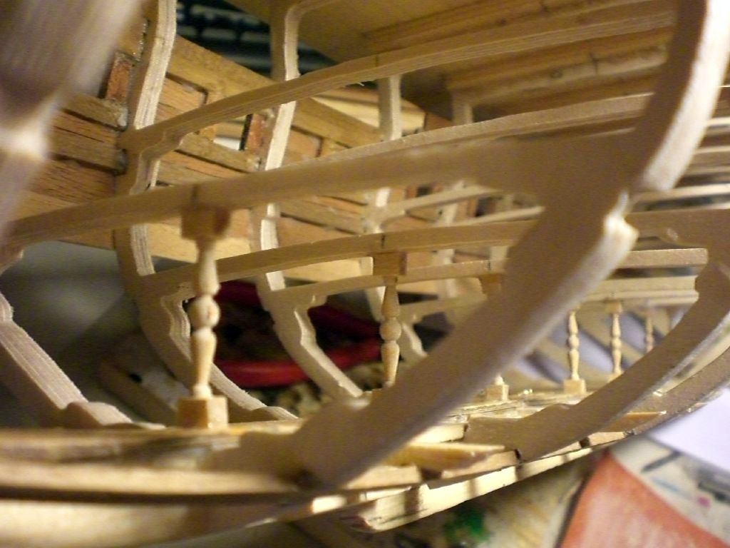
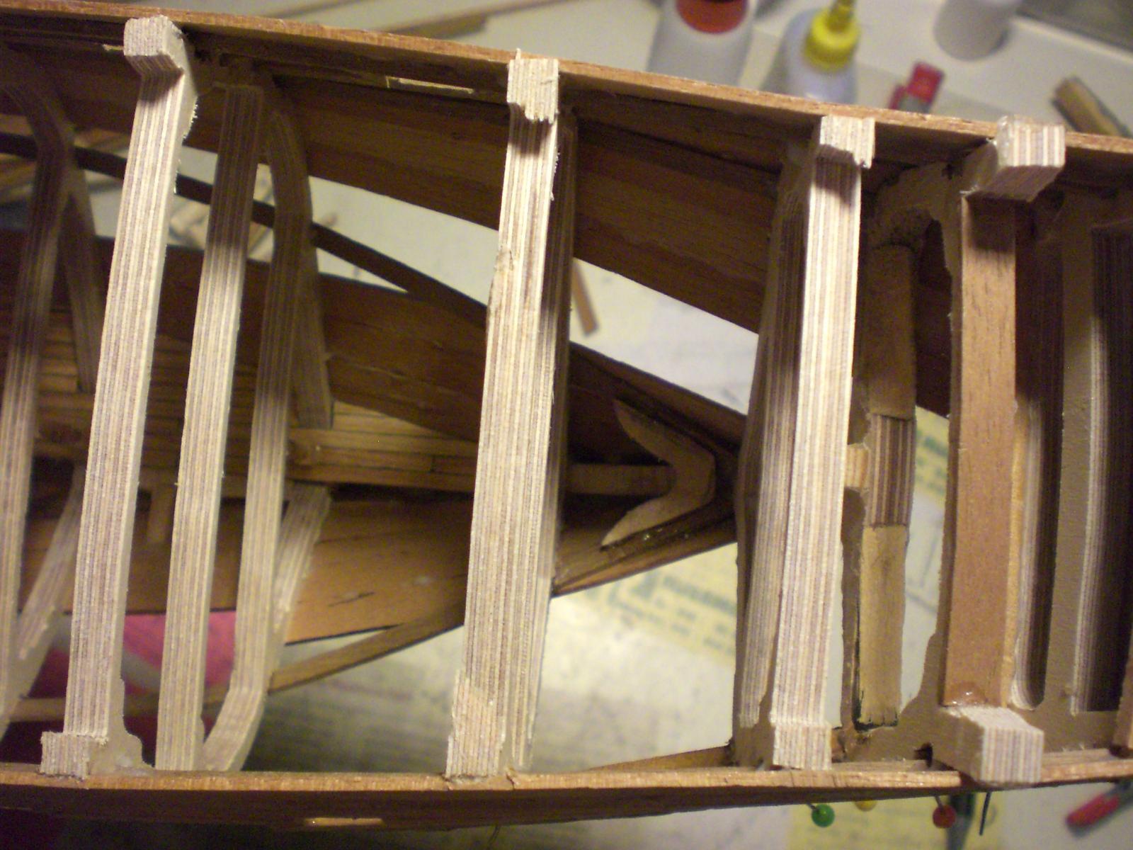
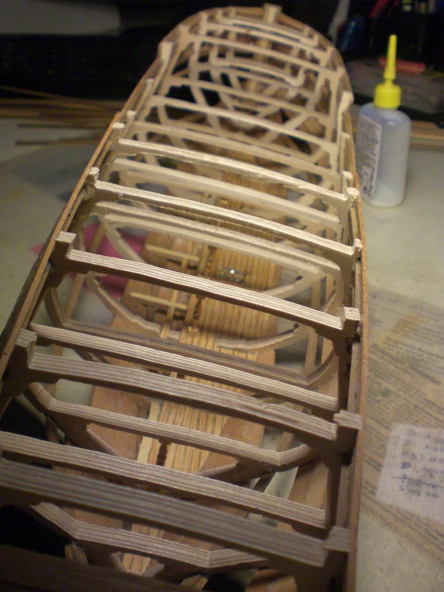
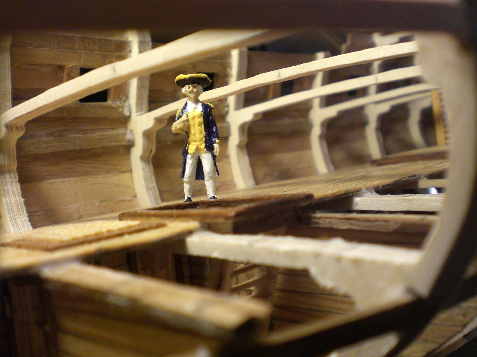
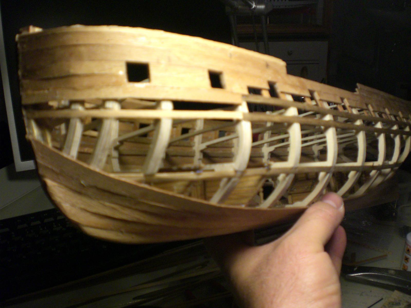
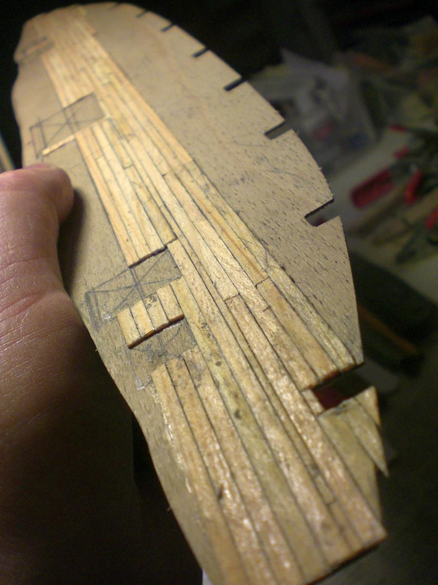
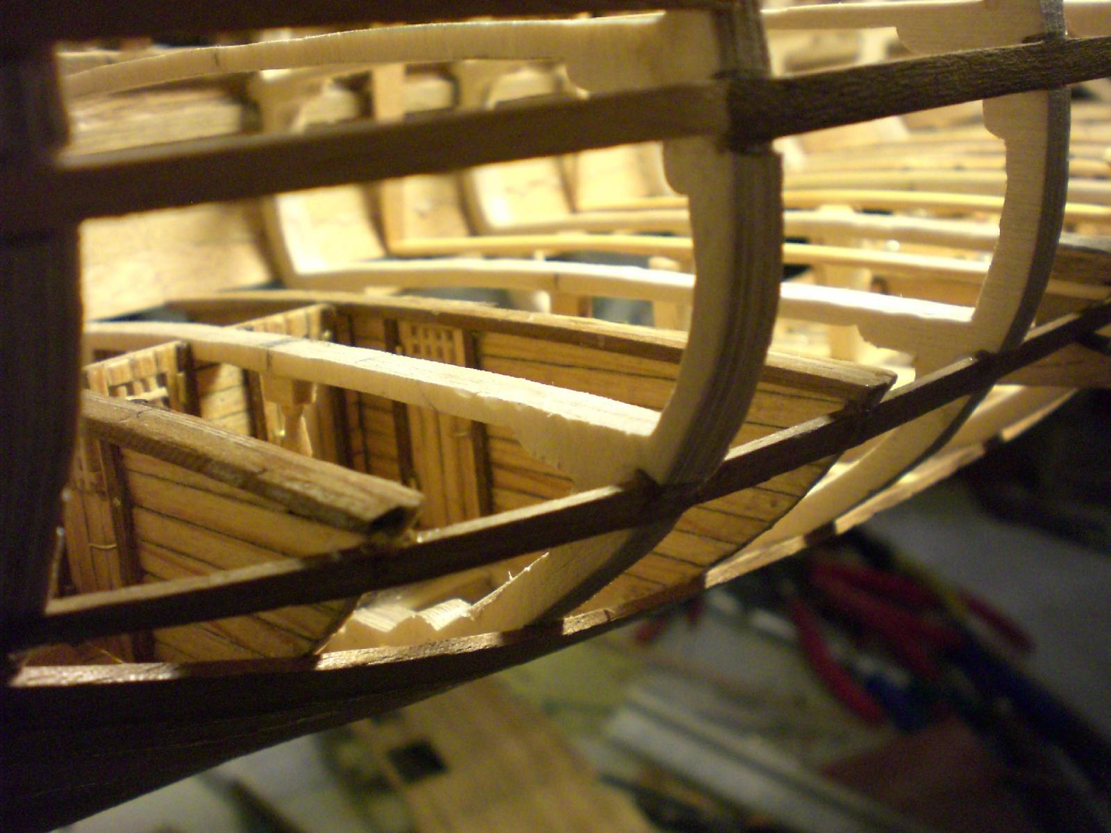
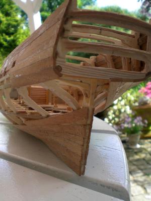
I finaly managed to get my first thread posted in this "scratch build logs in Progress" and under way. This is comprising the Swan Class Sloop Pegasus not from the kit, but by Amati / Victory Models plan, recently purchased from an Italian models distributer Internet shop. I also bought the etched brass Panels which carefully soldered in multylayer mode provide splended, satisfying results in 3D optic Appeal. For this model in 1:64 scale I have the intention to leave about 40 % of the port side Hull and decks unplanked, to scale the correct heights of all the decks and to fit the interior cabins and other operation facilities. Inspired by ways admiralty model displayed sight into the hull, the starboard side shall be completly tidy-planked in 1 layer structural planking. all frames are made from 10 layer ply in complete thickness of 5,5 mm. This allows to cut very filigrane and to keep the hight between decks to scalewise fit the tallness of the 1:64 crew. Appropriate to the stage of building I started to document all details in digitilised Fotos and would like to share these step by step with forum users / model builders showing interest. (more to follow) So here she goes...... (inclusive the first 10 pics) the Frames are taken from copies Templates out of the plan and fixed to 5,5 mm thick 10 layer ply10 , the rest is done by good old jigsaw cutting out. Notice appr. 30mm hight space between the 4 decks this base-board enables a straight twistfree build of the hull the Frames are extreme light, stiff and stong enough to withstand bending of stringers planking the 1:64 figures I used for Demonstration have 28mm hight this would be 1,79m in reality, presuming the 18th century seamen were smaller in those days, one I would recomend to use 25mm figures this in reality would be 1,60m forestanding pics should be self explaining, but notice that the bow and the keel beam is only supplementory. In order to avoid the time intensive rabet-cutting, the final bow- and keel wood beams shall be fitted after planking. This will give a clean and tidy look, as if the planking were fitted very precisely into actual rabets. I am seeking for means to edit the pictures with text explainations but find no "Editor" button, nor a "full Editor" one, allthough the pics seem to be in this post post, who can kindly help ? Reload...., so finally I think it works with the editing and text for zthe pics. At this stage my sincere thanks to all fellow members and Moderators who gave assistance in pushing out the boat ! So here follows the second lot of the build log Pictures and explainations the beginning of placing stringers and first planking importent step. Integrate at two places into the keel Little brick looking brass wedges with female M4 threads. These take up the stand bolts, M4, and allow secure model Display on stand, for later rigging purposes etc. self explaining pics, notice the sidewise fixed reinforcements at the wedge positions inspection hatch in cargo deck floor, to enable Access to bilge area two impressions of the bow area birds view of the keel Stern area, the Little pillars supporting the next higher decks, are from RB Models, Internet shop, in Polen This is presenting the third lot in my build log....... planking of starboard side is well under way. It comprises a single layer of 5, 6, and 8mm planking 1,5mm thick strips pf nutwood. Sanding down the outer roughnesses leaves about at least 1 to1,2 mm remaining thickness. cargo base deck is mounted. To answer the question how decks are placed into the hull? Pls note that they shall be slipped in from above. Is is easy because the deck is of 0,8mm ply and preplanked with 1 x 3 mm Planks. The shaping and Fitting is done from cardboard templates. Here the "shipyard baseplate" could allready be removed, as the lightweight hull is very riged and free of windings. Sbd side planked except for a few Planks where I Need Access to the interior. for those who are missing the square Little oar outcuts, pls note theat These will be cut in later on when the inner bullwark is being planked. I have bee able to avoid any gram of putty on the entire hull, because that would desturb naturak wooden optic. startet with "aft platform" room set up, but placed this on the cargo floor Level, even here the portside floor is open, right down to the keel showing the aft wall with the filling room inspection window here the lower well area including the shot locker, and visable the inspection hatch for the bilge Notice ! for interested forum users / members / staff, pls. be advised that this build-log shall be requently updated by editing this thread. If there is a better way of doing so, pls advise Nils This presents the fourth lot of my Pegasus build-log........ aft section with mizzenmast footblock upper well containment and outcut in intermediate deck for hold Access. Here either a safety railing shall be fitted or a grating (same grating size as on the gundeck in above place) aft staircase and grating Tower of upper and lower well and shotlocker here is an early Impression of how the unplanked port outcut shall look like eartly view on to intermediate deck from aft poopdeck the naval inspector has no objections so far. in the foreground the additional beams can be seen that rest on the strigers at appr. 3mm below decklevel, to allow appr. compensation in hight. one of the shipyard workers has just finished the days cleanup. Here it very nicely can be seen the 10 layer ply of the Frames, even though the total Frame thickness is 5,5mm only intermediate deck, ready for completing the interior operation rooms (use cardboard templates). Note that for better viewing from the outside, all the portside rooms shall be left away (will be crowded enough afterwards) Here comes the fifth lot for my Pegasus build-log view to the aft half view to the bow section quarters on cargo floor open port side, opening still to be reduced a bit preplanking of rthe intermediate deck view without the upper decks storage and Crew quarters in bow area the target was at this building stage, not to compete with the fabulous 1:48 scale "swan class Sloops" and their builders introduced in this forum in any way, but just to please myself for transferring own idias into humble modeling results and in scale 1:64 Nils