

Pat Lynch
-
Posts
103 -
Joined
-
Last visited
Content Type
Profiles
Forums
Gallery
Events
Everything posted by Pat Lynch
-
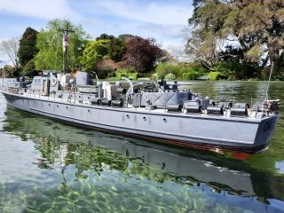
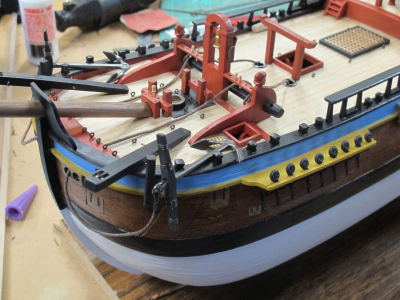
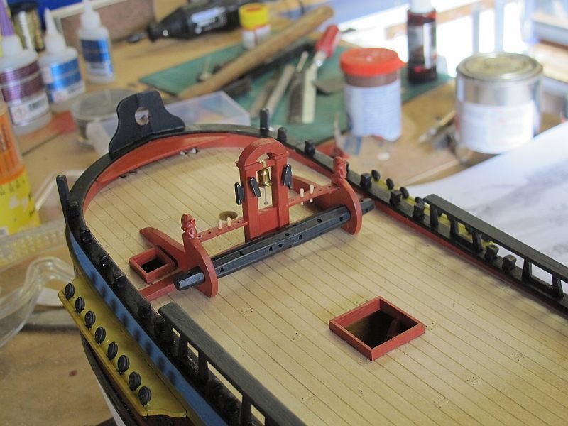
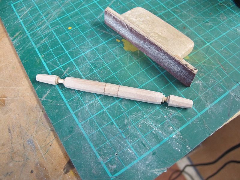
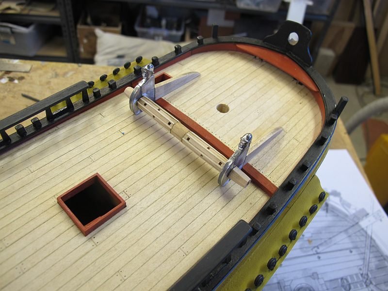
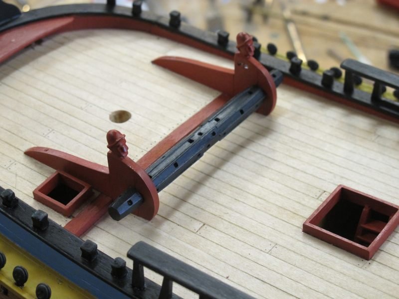
 It's been quite a while since I posted - spent a few weeks lazing in the Fiji sun on a large cruising catamaran, swimming, snorkeling and generally being lazy - wonderful! Back to the Endeavour. While away, I have been reading a new book - the AOTS of the Beagle - a ship, along with Shackleton's Endurance, that appeal to me as models. It made me realise that the Endeavour I'm building is quite a long way from 'reality'- whatever that is. So, I have decided not to try and make the A.L. kit too difficult but continue to gather the experience and skills needed to do better next time! Make the odd change where it seems appropriate but follow the construction notes (difficult at best) for anything I don't understand. The arc of eye-bolts in the bow is a case in point - maybe it was how the collier was setup but is certainly not a feature of many other models I've seen. So be it! The anchor davits and anchors were almost next on my list and were only slightly modified. The brass wheels provided for the cannon were given the task of being pulleys in the davit ends. The blocks and tackle for raising the anchor to be secured will be added next. The anchor cable's permanent position will be decided later - it probably depends on what stage of a voyage a static ship is representing - cable laid out on the fore-deck if ready to drop anchor or all stowed away when at sea. So much to learn, so little time 😊 Pat
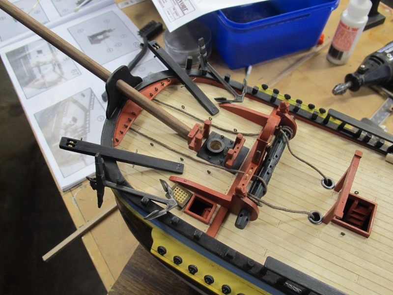
- 111 replies
-
- 6
-

-
- artesania latina
- finished
- (and 1 more)
-
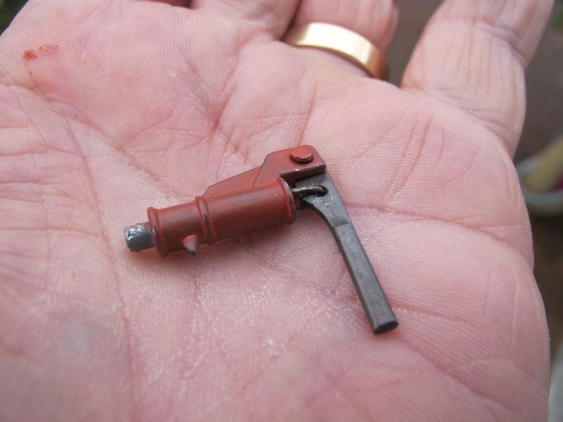
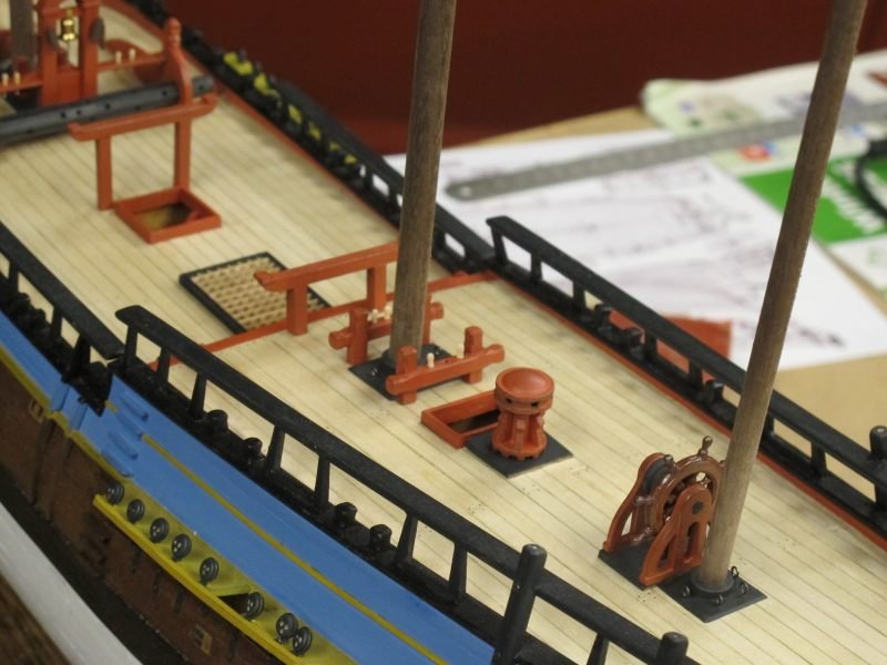
Thanks for the 'likes' folks The four pumps amidships puzzled me for a short while - I could find some parts in the bits boxes but bore no resemblance to the instructions - obviously the cast metal versions have replaced a rather clumsy wooden one that would need a lot of work. I could find no references to these type of main pumps online or in my model books so I just made them in a way I assumed were expected. But, I tried a few new techniques to make things easier down the track. Firstly getting the cast metal to accept paint readily. After a thorough filing to remove mould lines, a wire brushing and a scrub with isopropyl alcohol, they were given several VERY light coats of Rustoleum etch-primer. Then the final colour coat adhered well. The handle, because I wasn't sure if it was wood or iron, I gave it a quick dunk in Brass Black metal finish. Perfect A 1mm copper rivet secured the handle and a blackened eye-bolt made a rudimentary plunger to the stuff lower down. I don't have the Endeavour AOTS so it will have to do. Interestingly, the replica ship doesn't seem to have even dummy pumps. That space is taken by what looks like air vents (to the engines?) Which pump parts are wood or iron! If anyone can advise, thanks The pumps are not glued in place yet as I read that they could make the rigging harder later on........we'll see! I am procrastinating as to how the various companion-ways and skylight will be made - certainly different than the kit. Thanks goodness for all the kind folk who logged their own builds of this ship. Pat A rudimentary pump from the kit

- 111 replies
-
- 2
-
-
- artesania latina
- finished
- (and 1 more)
-
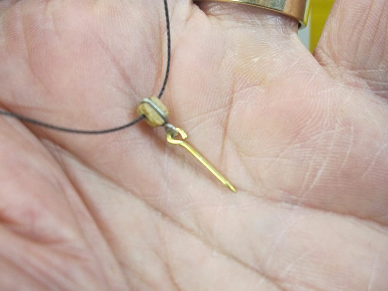
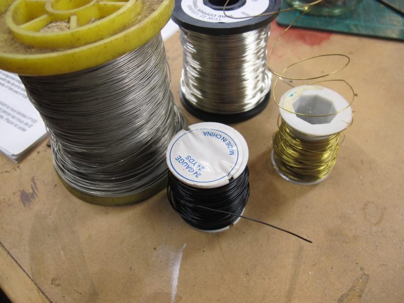
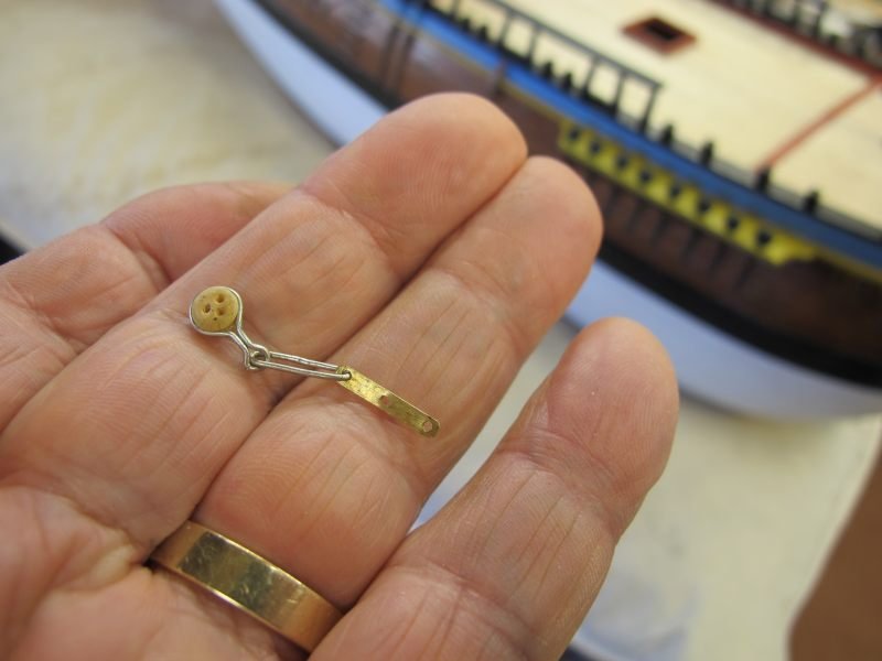
Thanks for the comments folks - yes I love the seemingly rapid day-to-day progress. I guess that will slow down when the rigging starts I decided to rig the rudder tiller and prepped a few of the smallest blocks - a light sanding, a coat of grain filler and a coat of walnut stain - they could be better but wasn't sure how much time to spend on them. I'm getting myself psyched up for rigging one of these days so hopefully things will be sorted by then! While rummaging around in a box of 'stuff', I found a treasure trove of wire! esp. the black-coated 24 swg steel. Perfect for strops on the little blocks. Apart from using them back-to-front (I think) they will work OK. The black beading thread is only to checkout the run of the rope. The horrible L.A. supplied 'rope' is probably OK when waxed - I'll try it tomorrow. The blocks all seem a bit over-scale but with my 75 year old eyesight, I'm glad they're not smaller btw, the design of the goose-neck is based on the replica. Pat

- 111 replies
-
- 6
-
-
- artesania latina
- finished
- (and 1 more)
-
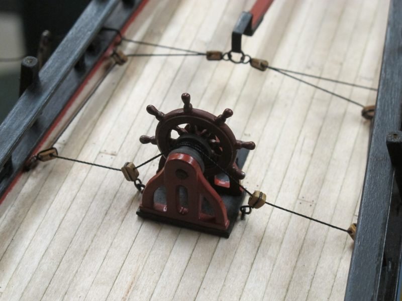
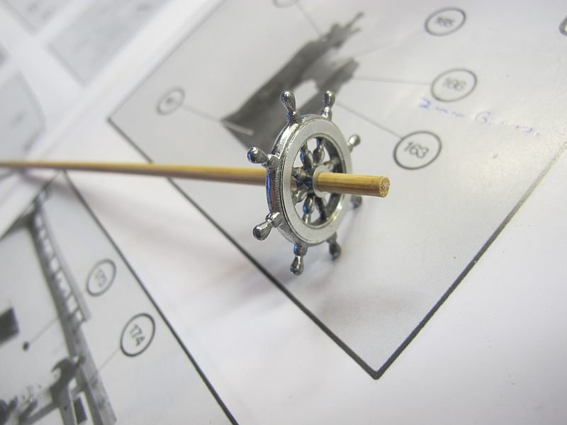
Every day or two - some more bits This basic fitting out is my favourite part of the deal. The frames that hold the spare spars, ship's boats etc were built up to look vaguely like the replica with curved and capped ends. Plus the capstan and the wheel were tidied up and fitted. The wheel was a bit chunky compared with the replica but it cleaned up OK. A bit of re-touching can be done later. I'll tackle the rudder linkage as my first use of rigging materials on this model which raises a question - does anyone use the rigging thread that comes with these kits? It seems a bit hairy and of rather poor quality. I have some beading thread that looks superb but not in the larger sizes. Banyan, ny good suppliers in Oz? Otherwise I guess a USA supplier can be found...... I cleaned up the wheel in the lathe - I was going to paint some brass décor but the replica seems to be all varnished wood so I left it at that Pat
- 111 replies
-
- 5
-
-
- artesania latina
- finished
- (and 1 more)
-
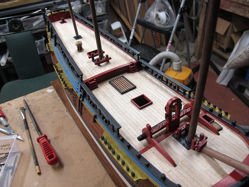
A few odds and ends done - as usual it is a mix between the kit, a few drawings (ex AOTS?) that I have found on the net, plus other's builds and of course, the replica! Add to that my own interpretation and it will be different from everybody else's The rectangular plates at the base of each mast don't show on the kit but are present on many models - are they flat iron? I made mine from 1/64" birch ply. Gratings are only being used in a couple of places - mainly the main hatch. I'll make up wooden structures and covers for the rest. This is the part of a build I really enjoy - doing small sections at a time. Heaps f fun on cold winter nights! Pat
- 111 replies
-
- 4
-
-
- artesania latina
- finished
- (and 1 more)
-
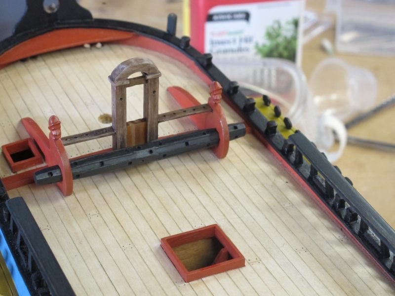
I'm reasonably happy with the windlass (lots of errors to remember for next time ) and so I charged on to the ships bell and its mounting. I wasn't keen on the supplied lintel so made a slightly more 'wooden' looking item from kit scraps using the replica as a guide. Some simplification was made but it gives a rough idea of 'a' real thing. Due to lack of observations skills and how my model was built, I made the belaying pin racks straight - not curved! Smack on the wrist for me........but at least they are there, unlike the kit plans. I was amazed that at this late stage I realised the Endeavour seems to use only a few belaying pins for the running rigging. Most 'ropes' are apparently tied off around the heavy railings - and I'd bought a bunch of tiny A.L. pins as I didn't see any in the kit! Another slap on the wrist. I haven't made the windlass pawls yet but will model them on the replica - just short bits of 1mm square stuff with dummy hinges. Well, that's the current thinking. The metal cleats provided seemed far too large at this scale so I filed about 5mm off the length and thinned them down somewhat. Still a bit big but more acceptable - only a couple of dozen more to do! Pat ps. I just realised the cleats should be brown, not black........
- 111 replies
-
- 6
-
-
- artesania latina
- finished
- (and 1 more)
-
Thanks Pat. At last - some structure on the deck. Not quite finished yet but the windlass needed a bit of work and will be OK when I've tidied it up a bit. The original kit parts were used except for the forward braces which should have been the same thickness as the windlass bearing bits. The drum was drilled through in the lathe and then reassembled after shaping and painting. I'll rough up the winding drum a bit to show some wear as shown on the replica. I'm going to use a mixture of the replica style pawls but only two of them! Just to be different! The square holes were easy with a 1/16" drill and a tiny square file. Time for a break! Pat PS - I seem to have got the pictures back to front. Apologies!

- 111 replies
-
- 3
-
-
- artesania latina
- finished
- (and 1 more)
-
Thanks Pat - I just spent an hour or so perusing your Victoria thread - lots of hints and tips to keep me on my toes! It's great to reach a goal or benchmark - but now the channels, lower deadeyes and their associated hardware are done. Not without many, many errors and mistakes but that is part of the learning curve. Biggest lesson is that I should have drawn or found a reliable drawing of the hull to get the placements of parts where they should have been So the main channels are a little too far forward (or the mast rearward), the chains and their anchoring plates are too far south - etc etc....... Like others, I had chains anchoring in the middle of hatches etc. I have since found a scale drawing on the 'net that can guide me in the future. It is probably an illicit copy (looks Polish) so wont show it here. Next time I'll get stuff right. The dead-eyes and associated bits are not accurate but look a lot better than the A.L. kit parts. After painting with dark grey Tamiya acrylic, the new bits were given a very light dusting with graphite dust with a soft brush - just enough to give a little bit of definition to the painted parts. And now, something completely different - staring on the deck fittings. Pat


- 111 replies
-
- 1
-
-
- artesania latina
- finished
- (and 1 more)
-
HMCSS Victoria 1855 by BANYAN - 1:72
Pat Lynch replied to BANYAN's topic in - Build logs for subjects built 1851 - 1900
Hi Pat - I read through your scratch build and, as expected, have seen enough new ideas and techniques to make my head spin! A great and unusual subject. Cheers, Pat- 993 replies
-
- 5
-
-
- gun dispatch vessel
- victoria
- (and 2 more)
-
Making mistakes is the best way to learn - I've made heaps and am still very much a beginner Do you have a photo of what the completed model will look like? The deck planking looks interesting! Pat
-
Very small offering today - just to prove I'm still working - the remaining 20 lower dead-eyes and the related bit of hardware 'in the rough'. Now they all need cleaning up, a bit of re-shaping and assembling into the port side channels. Nice to get all the bits ready to fit instead of doing them bit-by-bit as I did the other side. Still having fun on a rainy, wintery day (it's still Autumn really...Pat

- 111 replies
-
- 2
-
-
- artesania latina
- finished
- (and 1 more)
-
About a weeks work (much of it experimental) I have the starboard channels and the lower deadeyes fitted. Certainly not a perfect job but I'm happy enough. My motto is "..I'll get it right next time.." but that supposes there is a next time, or more likely will I remember the mistakes I made this time Without the expert reference materials I now know are available, the shortcomings of the A.L. kit plus my lack of model ship building knowledge, this model is bound to be a bit of a mix of right, wrong and 'does it matter'! But it will have been a fair effort I hope.......enough rambling and face the port side with enthusiasm and a little more knowledge Pat
- 111 replies
-
- 2
-
-
- artesania latina
- finished
- (and 1 more)
-
After suffering a minor computer 'malfunction' (read - finger trouble) I can post a little progress! Fitting the channels was the next logical task (and next in the instructions) so they were prepped, painted and fitted to the starboard side of the model. Some of them needed a slight curve to follow the hull lines and so were steamed and clamped over night. With channels fitted, I looked at ALs version of the shroud deadeyes and their fixing and decided to do a little better - esp. after seeing some of the excellent build on this forum. So I found a roll of 22 swg tinned copper wire and proceeded to make the various parts needed. I also made the plate that fixes the 'chain' to the hull with some thin brass about 2mm wide. It's all very laborious but 1/2 the deadeyes have been prepared and I did the mizzen channel for practice. They can only get better . So I have a long task ahead getting around the ship. More details when it gets more interesting! The surgical tweezers were great to clamp the wire while the eye was being formed around some 1.5mm rod. Pat


- 111 replies
-
- 2
-
-
- artesania latina
- finished
- (and 1 more)
-
Dan - you're welcome. The transom rail was made from a lamination of 1/32 and 1/64 ply. I looked at replica photos, plus a plan published on the net and got a rough facsimile of the real thing. I may have a bit too much curve in the rail but it is similar to the replica but at odds with the kit and other models. Ah well - it is MY interpretation It seems to be mostly a structure to tie various ropes to - but that will be much, much later Another coat of paint and some retouching of the painted areas tomorrow........Pat


- 111 replies
-
- 3
-
-
- artesania latina
- finished
- (and 1 more)
-
Lovely work on a beautiful model Jean-Paul - inspiring Pat
- 103 replies
-
- 1
-
-
- queen anne barge
- Syren Ship Model Company
- (and 1 more)
-
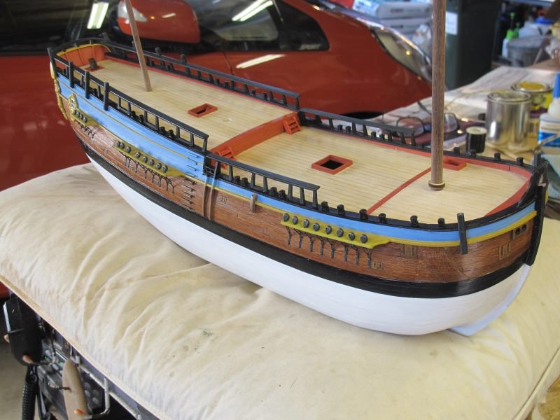
Some more of the hull details were added - the decorative yellow trim on the quarter deck upper hull sides and some dummy hinges on the various side hatches/openings. The yellow strip is 1 X 1mm plastic from the Evergreen stand in the local hobby shop. It was painted yellow on three sides and the rear scraped clean for gluing. The path it would follow was scraped back to bare wood with a #11 blade (only a scratch really) and the strip held in place while a tiny drop of thin CA was applied along a short distance. The process was repeated along the strip until it was secure. Almost no sign of the glue as it was wicked between the plastic and the hull. Looks OK from a distance! The 'hinges' are just tiny pieces of thin black card about .75mm wide fixed with thin CA. The opening direction is what I could glean from various replica pictures.....not always correct possibly but they look subtle which is what I wanted. The bigger hinges have tiny spots of PVA glue applied as bolt heads. They are almost invisible but I know they're there Next, I'll do the poop deck rail across the transom top - it seems to be curved in two directions so I may laminate some .4mm ply and cut it to shape. We'll think about it. Pat
- 111 replies
-
- 4
-
-
- artesania latina
- finished
- (and 1 more)
-
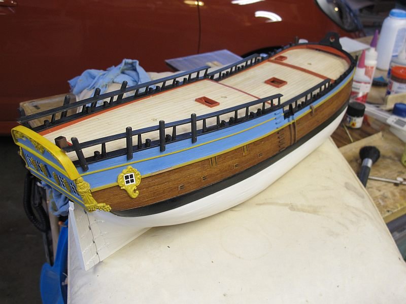
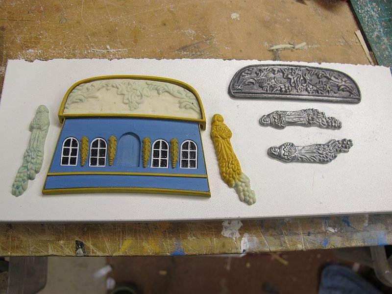
Back to building......The final bit of exterior decoration to be done at this stage - the Port side window at the rear - again from a resin casting and a little window frame added from thin plastic sheet with four panes cut out (a pain) backed by a piece of black-painted plastic. White glue (canopy cement) was run into each pane to simulate old glass. I thought that was all the decorative stuff but I wanted to do the thin yellow moulding/batten/strip that runs around the quarter-deck hull sides (on the replica) at just below deck level. I'll have a go.......tomorrow. Pat

- 111 replies
-
- 5
-
-
- artesania latina
- finished
- (and 1 more)
-
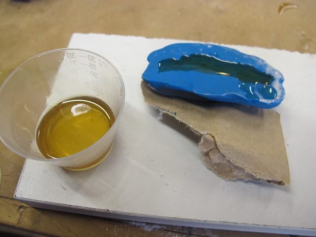
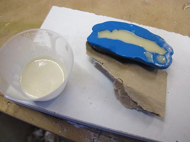
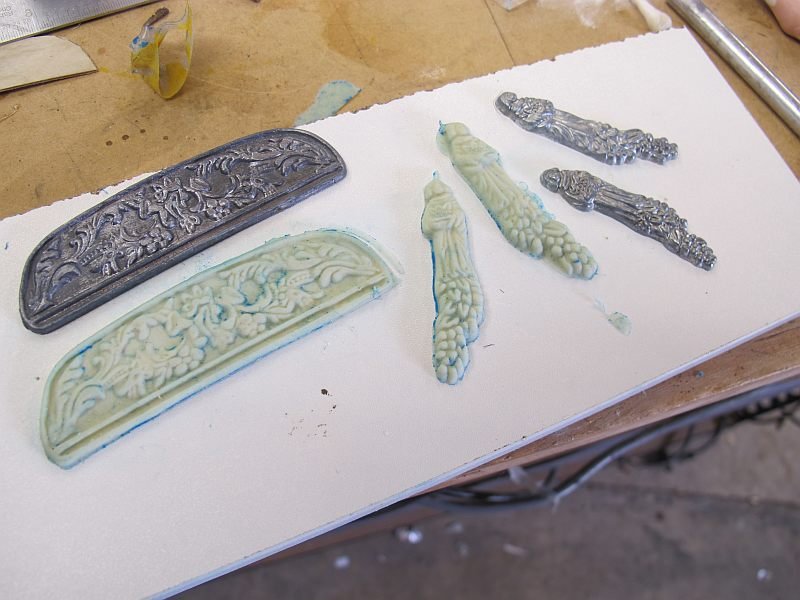
'.....I did it my way....' I am starting with that disclaimer because this was my first time at resin casting and revealed a few pitfalls and may some folks can benefit from my fumbling attempts For a one-off casting, I used the plastic clay supplied in the mini-kit. It is easily moulded and with care, makes a good basis for small objects. Make sure the clay is nice and malleable by squeezing it until soft BUT avoid folding it over on itself like pastry as it can leave creases in the 'dough'. The object to be copied is washed clean and can be given a clean-up around the edges with a file but do not get too fussy - the resin copy will be much easier to tidy up! A dusting of baby powder over the object will make it easier to remove from the clay. Lay the object on a smooth surface and mould the clay around it, examining a few times to be sure it is making good contact all round. Then carefully prise the object out of the clay (it may even fall out if held upside down). and place the clay mould on the bench so the top is level. Mixing the 2 part resin is the trickiest bit. The quantities must be EXACTLY the same to ensure success (unless you are very experienced ) It is suggested that the parts A and B be measured into separate measuring cups and then combined into a third as some liquid will stick to the cups after pouring and may cause unequal amounts. Mix the combined liquids thoroughly and quickly - a minute is about all you have before pouring into the mould. The brief user notes suggest mixing a bit more than needed as it makes getting the small quantities more exact. I used about 10 + 10 mils -a fair bit of waste but if you got all the castings ready at once, it'd be more economical. Dusting some baby powder into the clay mould and blowing out the excess is suggested for an easy removal. The resin will change from clear-ish to off-white when nearly cured - wait at least 20 minutes before very carefully easing the clay away from the casting which can be left for a while to fully cure. It seems very small or thin parts such as I did may take longer to fully cure. I found some of them only became fully rigid after several hours. Some warm sunshine might help! Any residual clay can be washed off with warm soapy water before working with the resin casting. What you do from here is entirely up to you The resin can be sawn, filed, sanded, cut, scraped and seems very easy to work with. I found it better to wait a day or so before painting and certainly give it a good washing first. A flat white acrylic seemed to prime it OK and Tamiya acrylics have dried OK. Medium CA works as an adhesive but I've not tried other glues....... Sorry a bit long-winded but I hope it helps. It's easy after a few trial objects. Again, this is just my personal experience as a first timer! Pat


- 111 replies
-
- 2
-
-
- artesania latina
- finished
- (and 1 more)
-
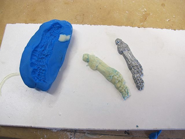
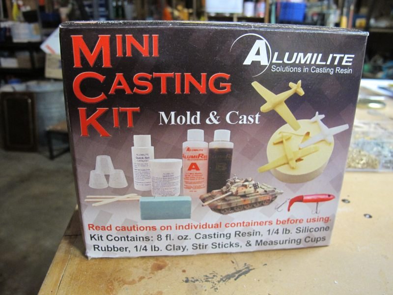
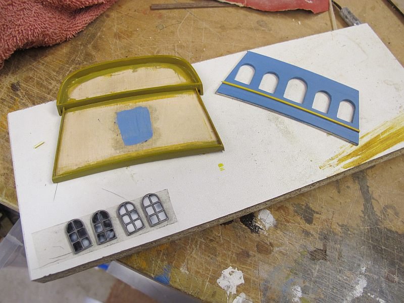
Whoops! - measure twice, cut once....... Thanks folks - nice comments help keep the project alive However, I still make big errors - carefully positioning the first of the side windows under the wrong cannon post. Right where the mizzen channel will be So, a quick repair job and try again! The decorative frame around the window was a bit heavy in metal so I cast a pair of them from resin. This also gave me the opportunity to give the window opening a bit of slant - sort of like many plans and pictures show. Not quite right I know but it gives it my own touch. The great thing about resin is it is so easy to sand, cut, carve, scrape etc so I made these items about a mm thinner and they curve to match the hull. I pushed them against the hull before they completely cured. I have shown the little US made kit I am using and I'll try and give a bit of 'how I did it' next! But I AM a beginner and tend to do it my way. Cheers and happy Easter to all. Pat

- 111 replies
-
- 4
-
-
- artesania latina
- finished
- (and 1 more)
-
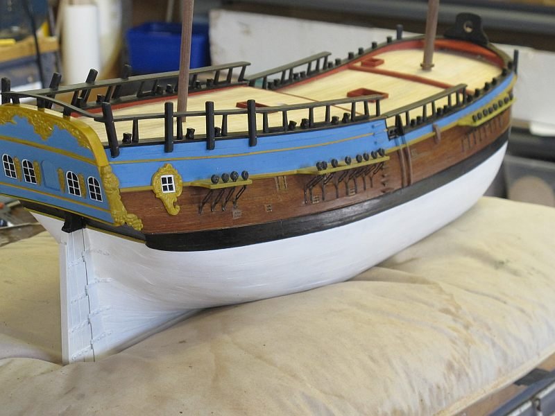
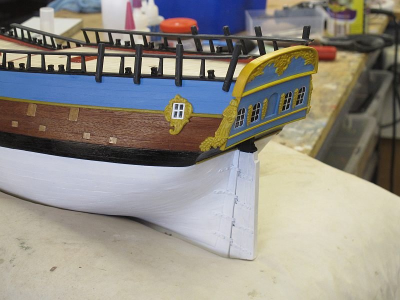
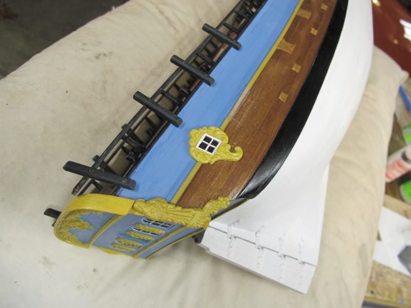
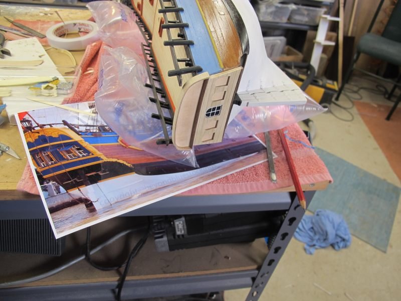
A little progress. The transom and the ornate upper panel have been final fixed to the stern The starboard decorative piece (or the resin copy) was cut and repositioned in a manner similar to the replica ship. I am aware that the actual figures and motifs are NOT the same as the replica but I have used the photos to try and better position my copied kit parts. It's the idea and appearance I wanted. It would be a lot more work to completely redesign them and most of my friends wont notice. I've now got to tackle the port side figure in the same way. The replica has her standing on a small flat base above the lower part of the decoration so I did that to break the item into two separate sections and get the bottom part at a better angle on my model. OK -it's a sunny day here in Inglewood so back to the garden........ btw, the brown line on the lower stern between the black and white areas is a molding that will be painted yellow at some stage. I'd forgotten it was there until looking at the photos Pat


- 111 replies
-
- 2
-
-
- artesania latina
- finished
- (and 1 more)
-
Thanks Pat. Having 'bodged' my way out of trouble, I now am attempting the resin replication of the somewhat crude metal parts - mostly the main decorative panel on the transom and the two side carvings (ladies with grapes) that I want to modify. After some experimenting, I got several near-perfect resin reproductions using a lump of plastic 'clay' as a mould. The metal items were dusted with baby powder and pushed into the clay to make the shallow impressions. The resin (part A and B ) were mixed EXACTLY 1 to 1 and poured into the moulds - 20 minutes later the resin versions were extracted Excuse me jabbering on - I'd never done a resin casting before and it seems to have worked. A little extra heat was applied to the resin items later to help complete the curing in such thin items. My aim is to remove a lot of the main panel to give a similar look as the replica. Not the same but I like the look. A work in progress for another day! Pat

- 111 replies
-
- 4
-
-
- artesania latina
- finished
- (and 1 more)
-
VB - I hope it all works out! My fall-back is always the original parts.... Finally the transom stuff is ready and waiting for the decoration. I'll fix it in place when major work is finished. I'm learning a lot as I go and, as always, wish I'd done earlier stuff differently. Cant get it all right on the first model! - first serious one that is......Pat
- 111 replies
-
- 4
-
-
- artesania latina
- finished
- (and 1 more)
-
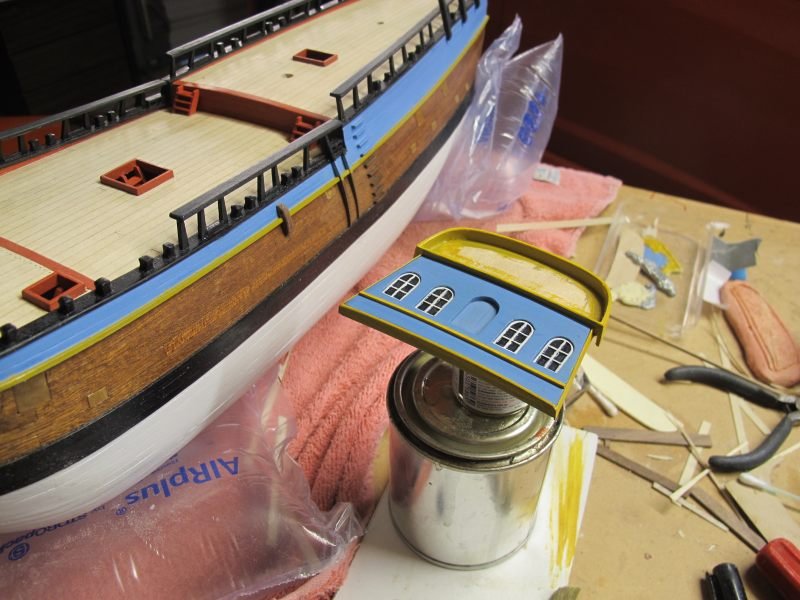
There - fixed! I replaced the transom 'capping' with two bits of Birch ply - .8mm + .4mm. 1.2 vs 1.6. I'm happier now The transom I've divided into a few separate sections to make construction easier - the back board, window panel and the decorative panel above. I'm hoping to almost finish each section before installing on the stern. The supplied windows will do fine - the castings are crisp and fit snugly into the cut-outs. I tried out the painting of them on the redundant centre window. The black glass panes were done with a permanent marker pen (a cd/dvd marker) and then a drop of model aircraft 'canopy cement' was spread around to give a nice glaze. Hardly noticeable except by me I'm getting closer to seeing solutions to the transom area, Hooray! Pat
- 111 replies
-
- 4
-
-
- artesania latina
- finished
- (and 1 more)
-
A bit more experimenting. I reshaped the transom ply parts to suit my model and added the top edging as is done on the replica. BUT. I forgot to narrow the ply by the added thickness of the edging and also made it a bit too thick. I used two pieces of .6mm Bass ply plus 1 of .4mm Birch ply - about the thickness of gunwale top. Now I see the replica has a much thinner section so after a spell of mowing lawns, I may redo it and kill two birds with one stone. But the idea is coming right (I think) Part of my problems is that the back end of my model seems to lake the shape the ply transom parts suggest it should be! I must have misread the instructions somewhere. Instruction?????? What instructions.........


- 111 replies
-
- 4
-
-
- artesania latina
- finished
- (and 1 more)
-
They say a picture is worth a thousand words so what have I been doing? One of the most contentious and variable interpretations on a model Endeavour seems to be the transom décor! The cast metal provided is a bit 'clunky' but I figured with some work, it could be the basis for my model. But the metal is very difficult to work with so I am experimenting with casting polyurethane resin replicas that I can easily carve, sand and generally adapt to 'my' Endeavour! The cast windows look crisp and tidy so I'll use them as they are. I'll leave it there as I need some fresh casting resin - mine is about 10 years old and makes rubbery mouldings! Pat


- 111 replies
-
- 3
-
-
- artesania latina
- finished
- (and 1 more)