HOLIDAY DONATION DRIVE - SUPPORT MSW - DO YOUR PART TO KEEP THIS GREAT FORUM GOING!
×


Richard44
-
Posts
429 -
Joined
-
Last visited
Content Type
Profiles
Forums
Gallery
Events
Everything posted by Richard44
-
 Thanks Maurice.
 -
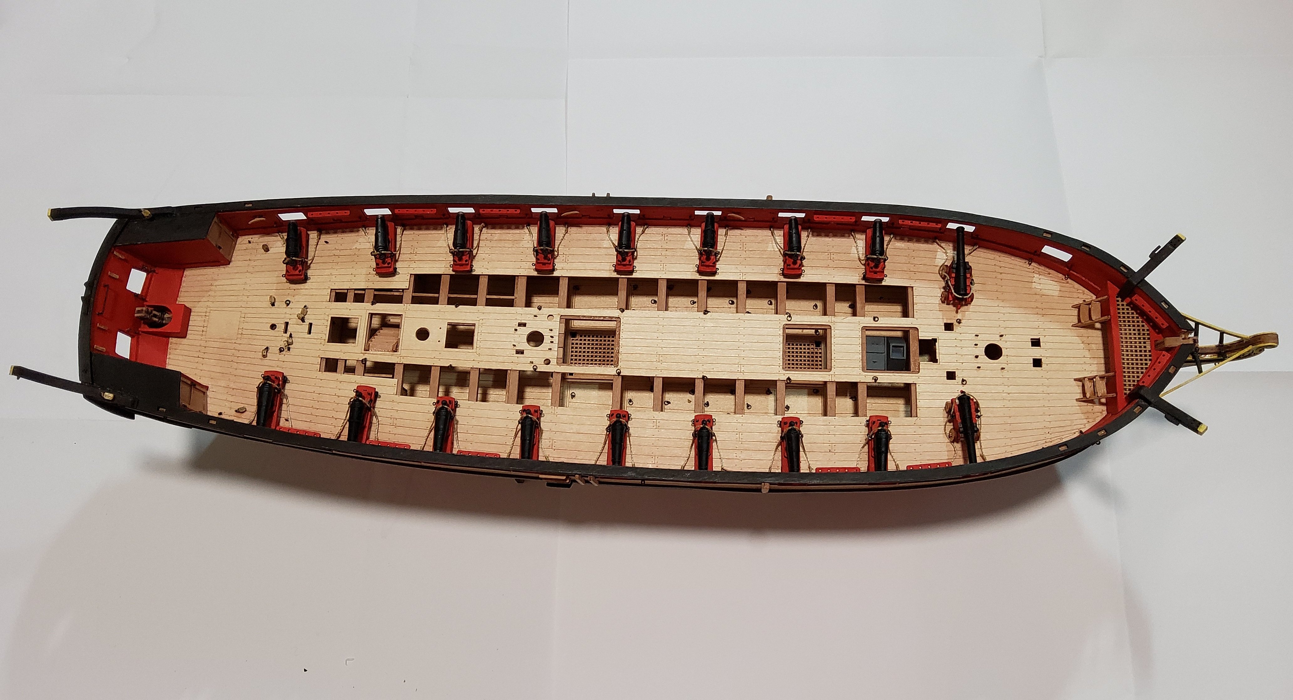
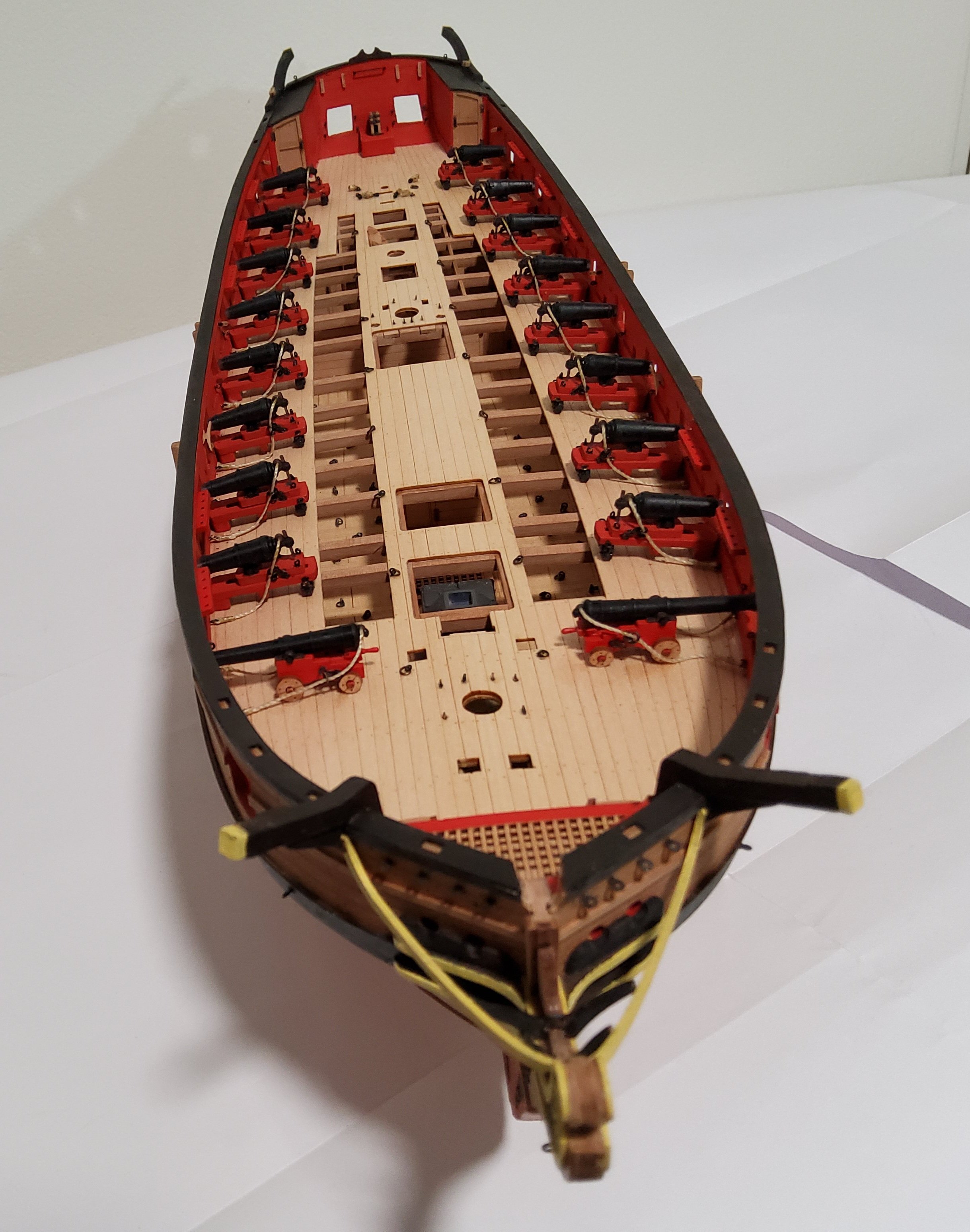
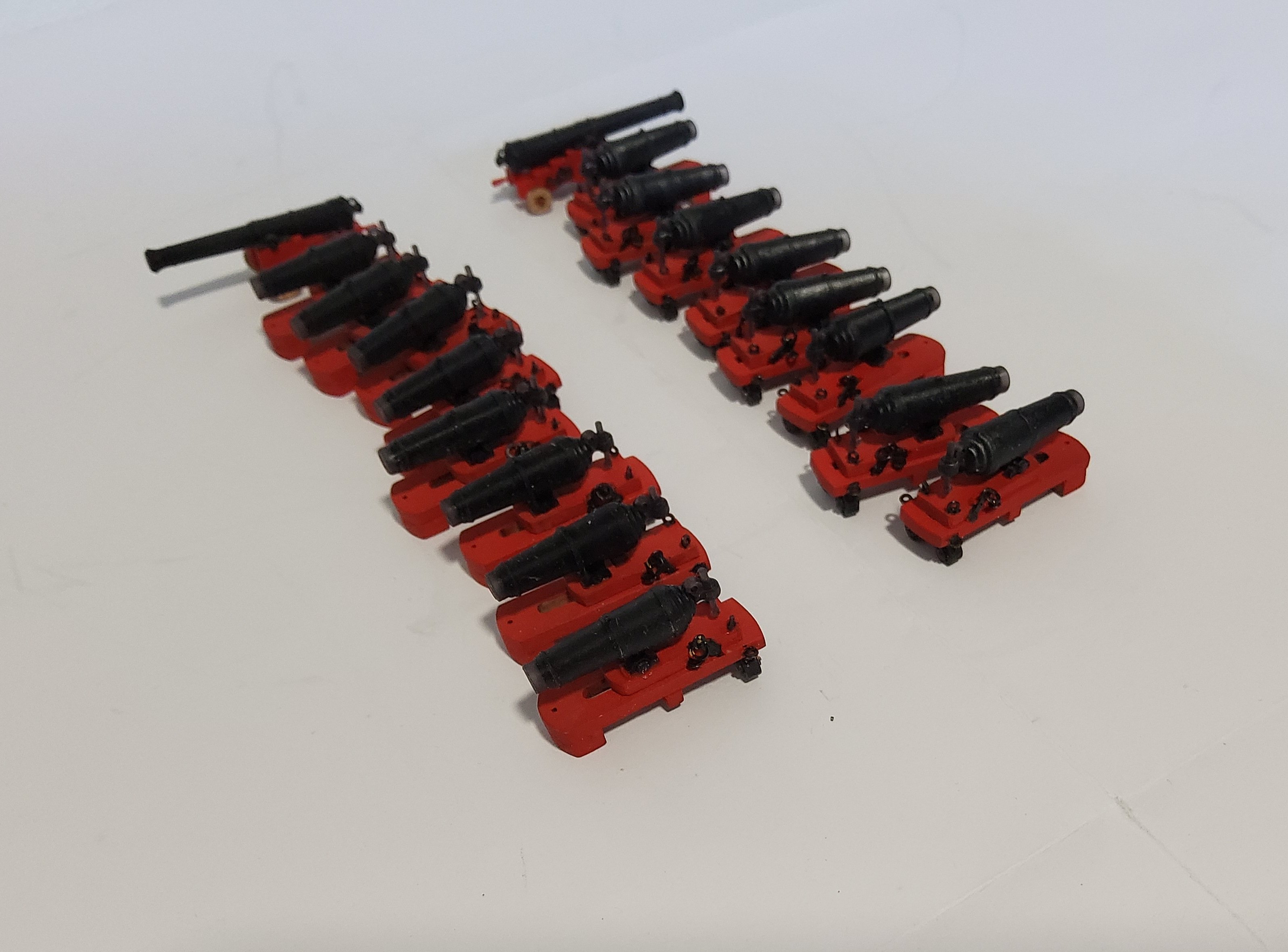
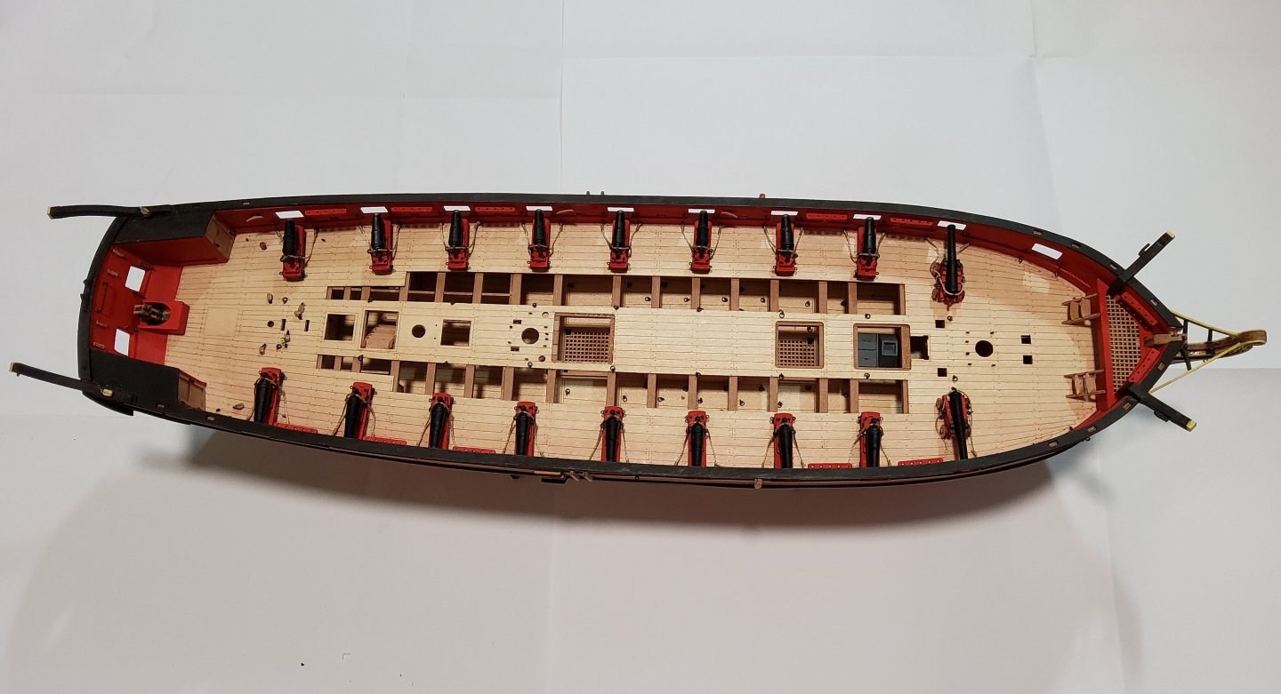
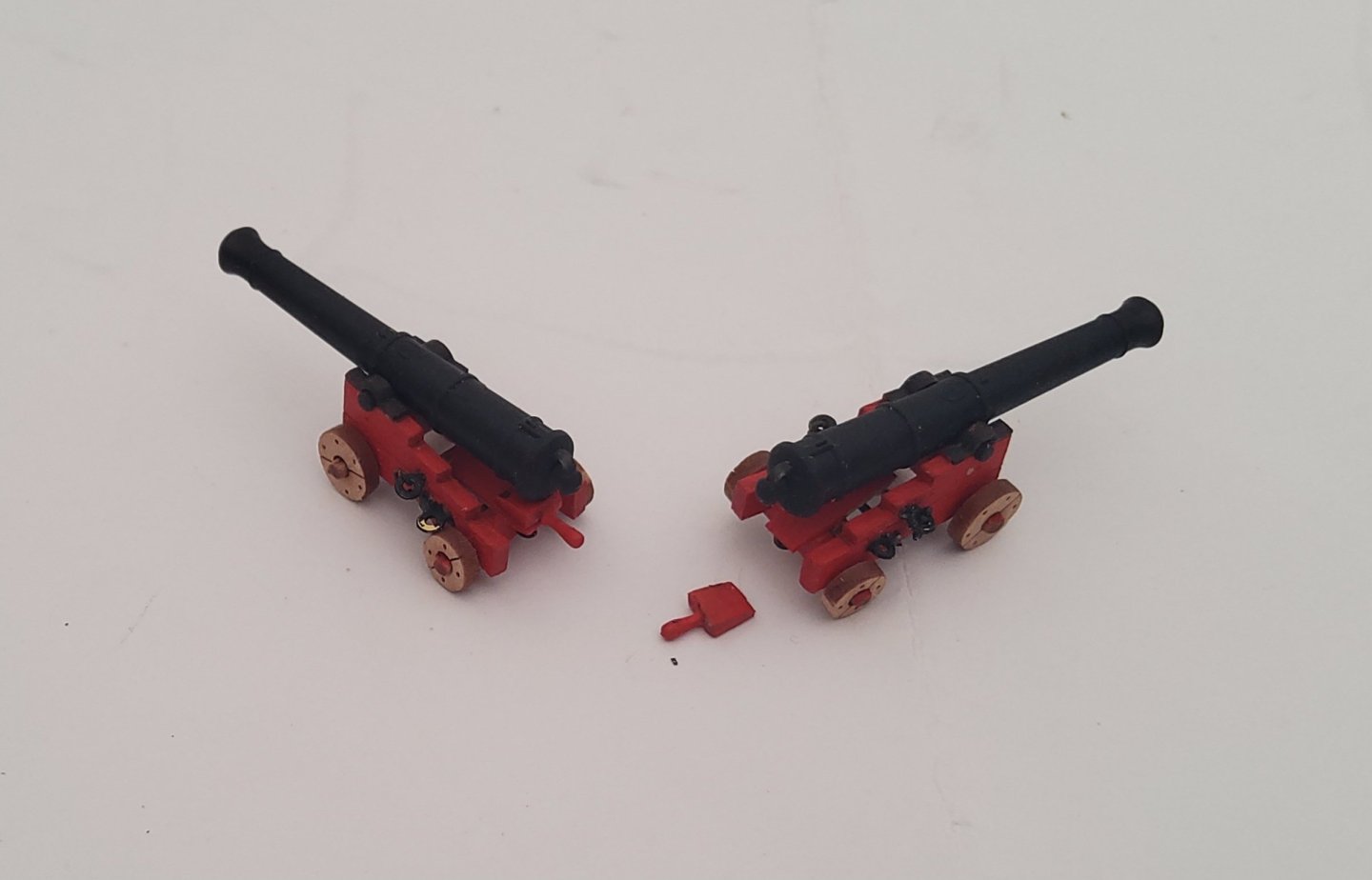
Progress has been slow due to lack of spare time. Nevertheless there has been some. The guns are finished and in place on the ship. Only the breeching ropes were rigged and this was done off-ship. Cheers


-
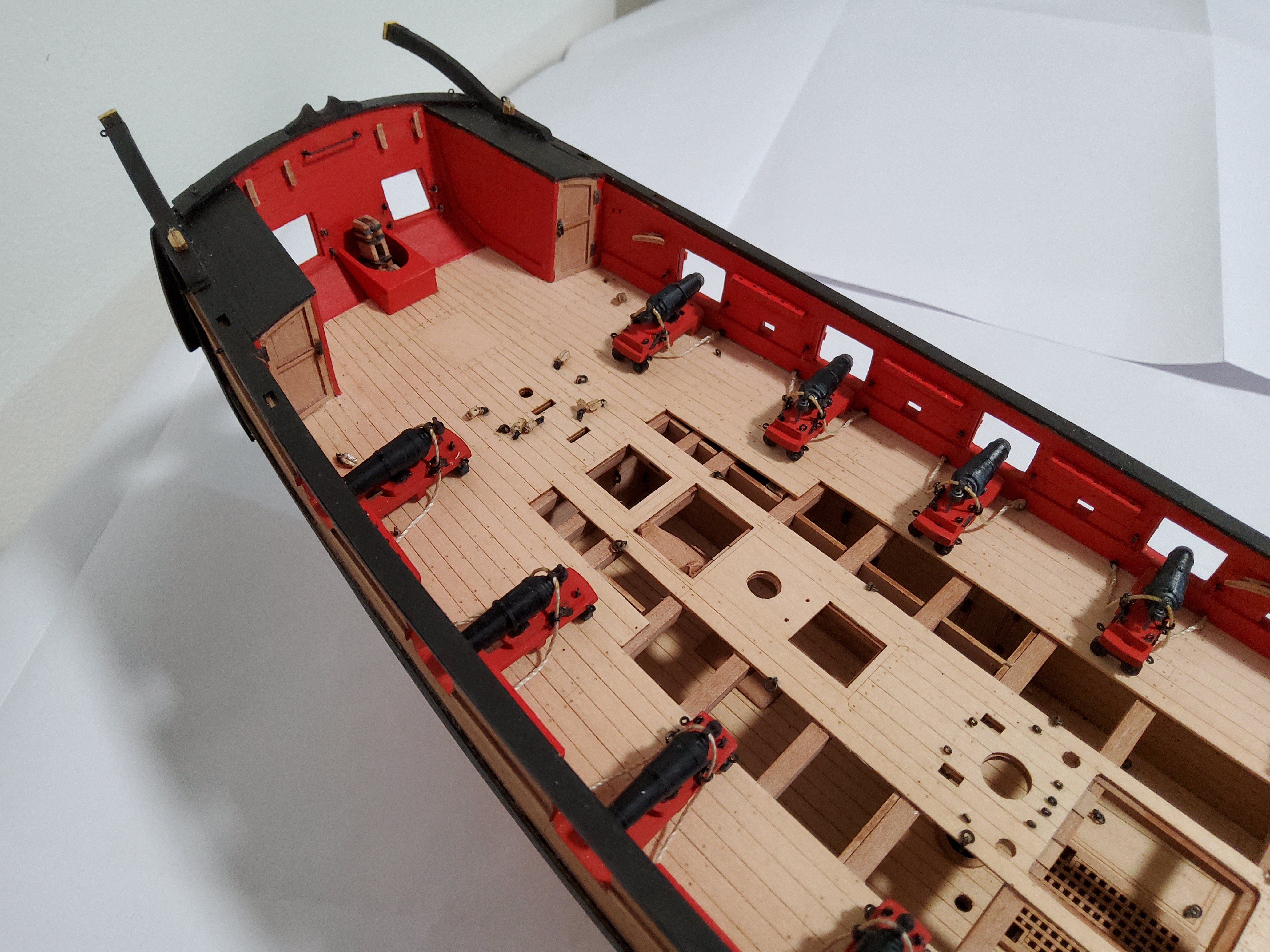
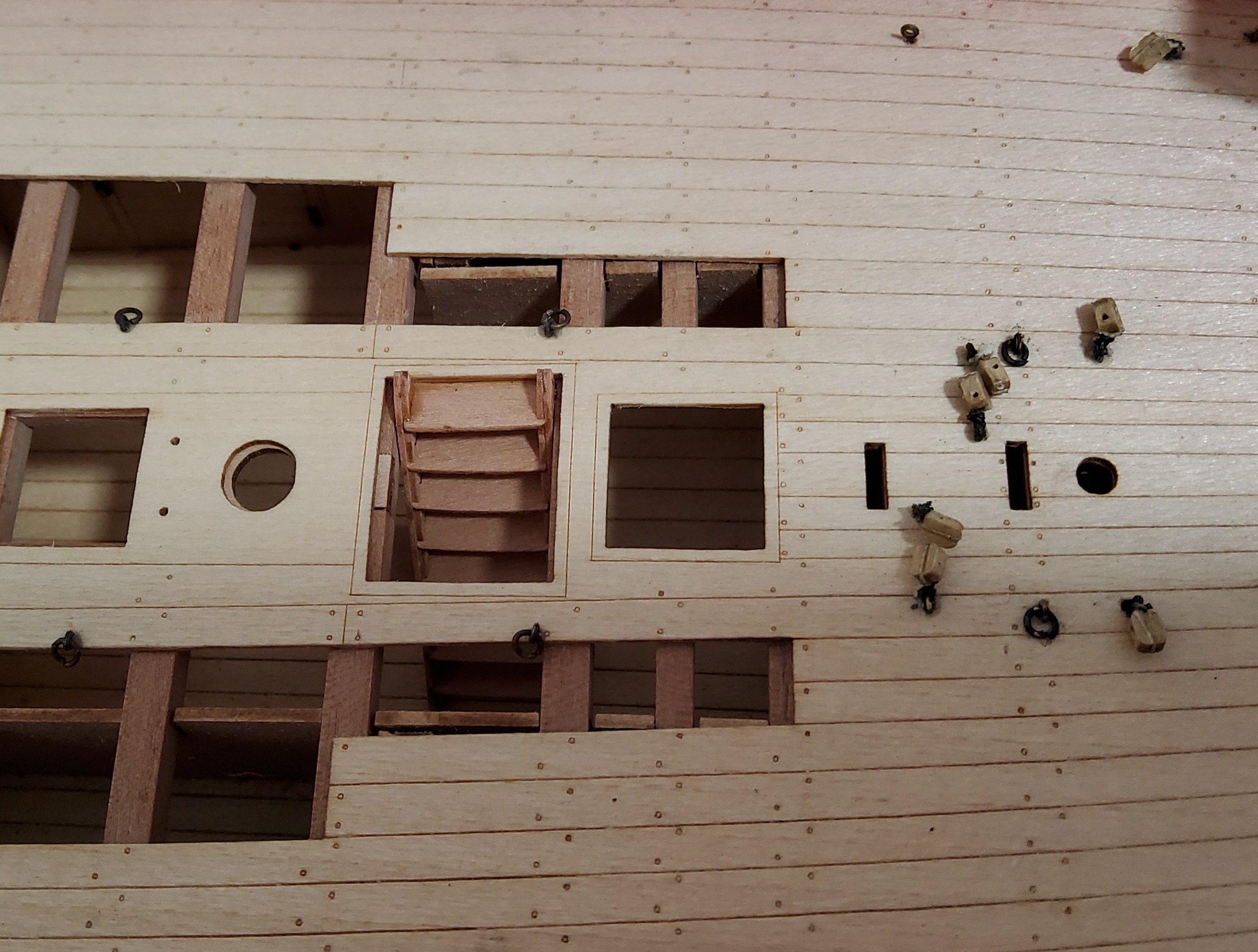
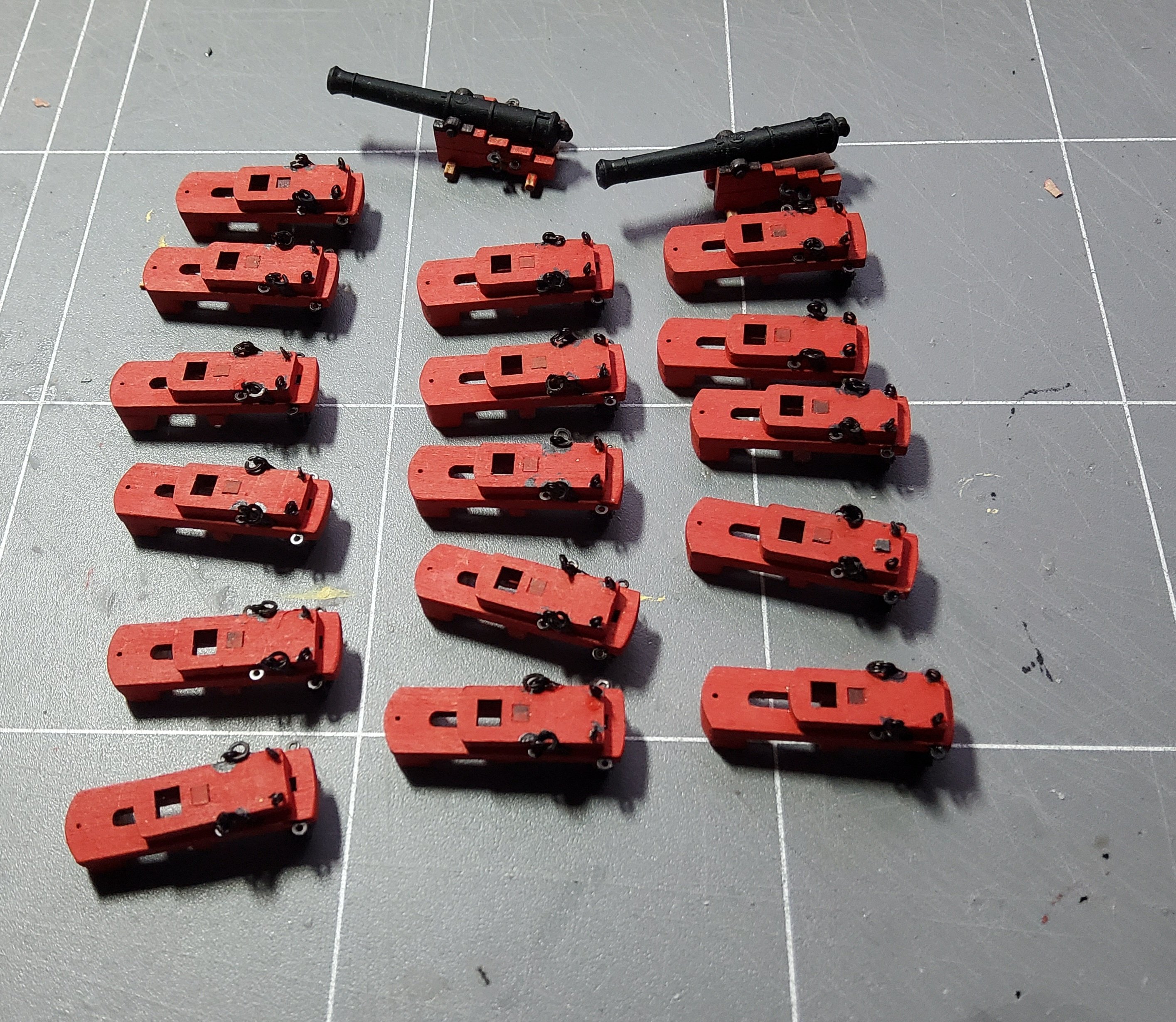
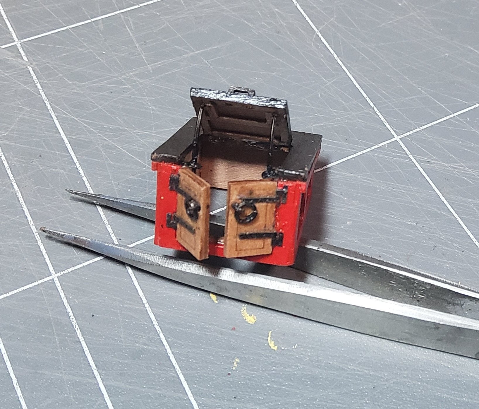
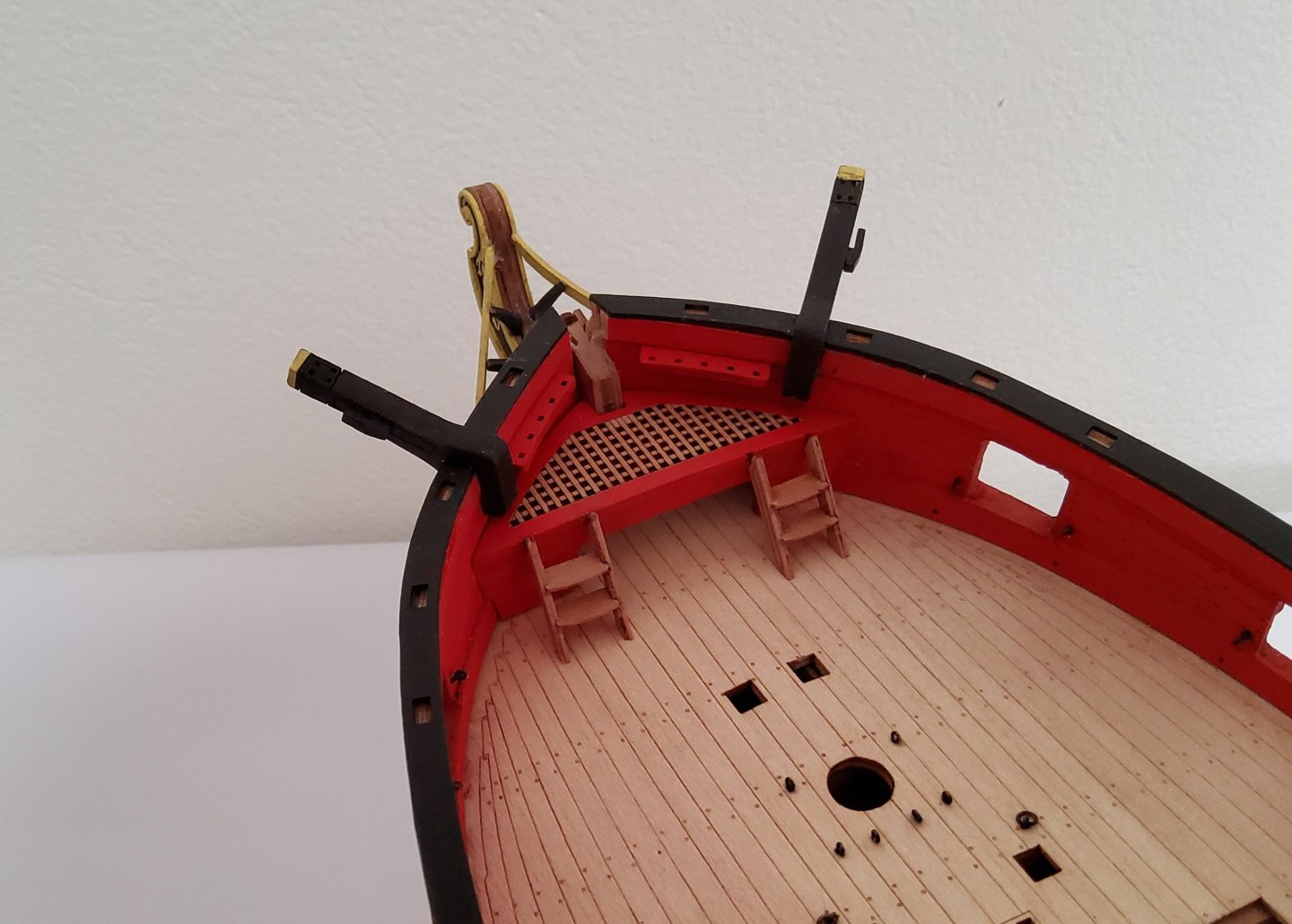
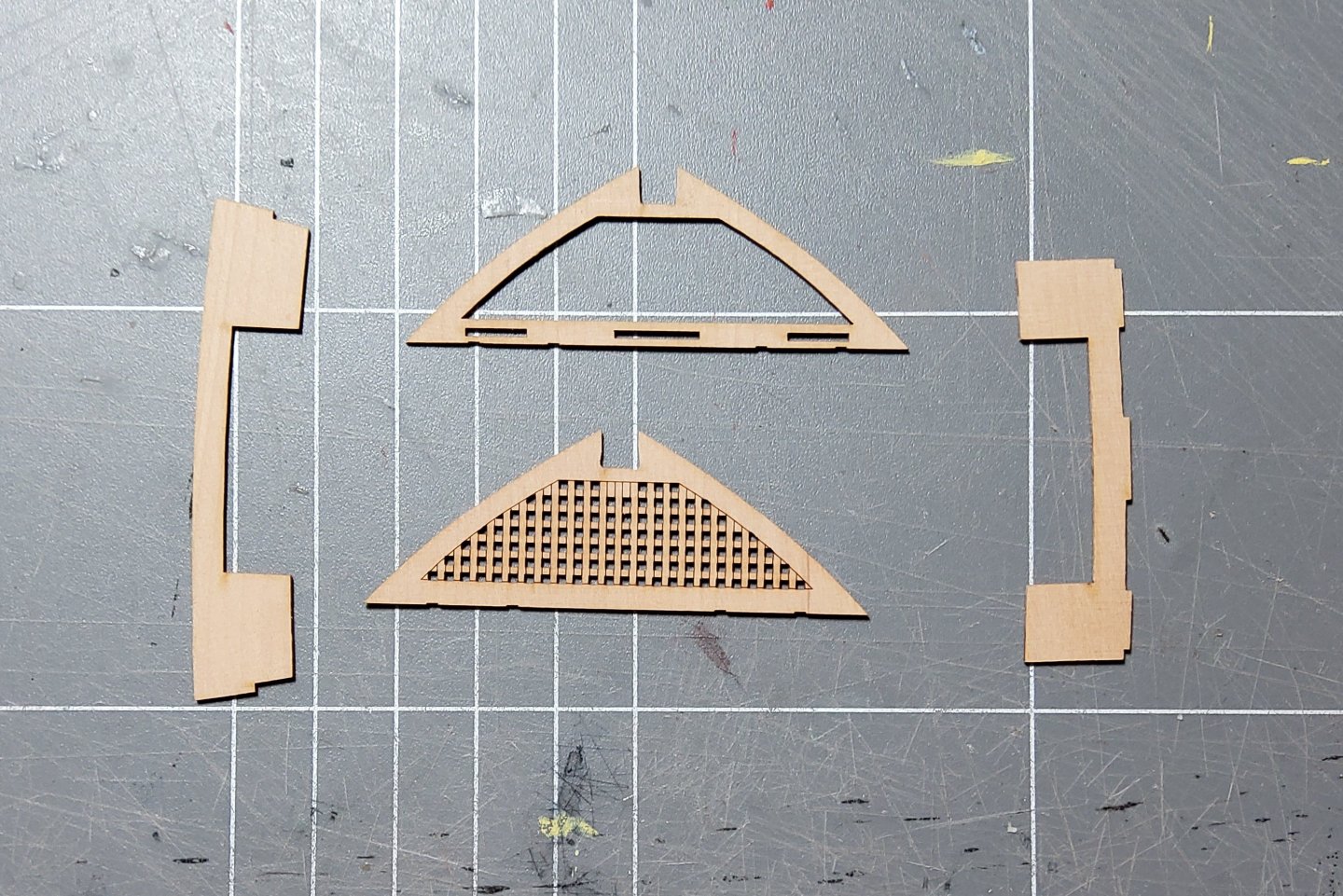
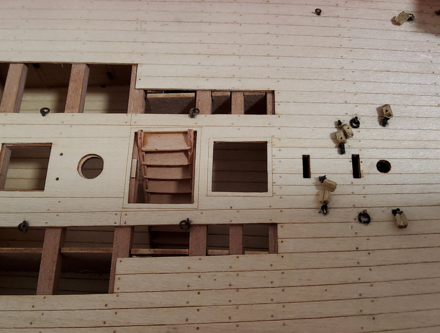
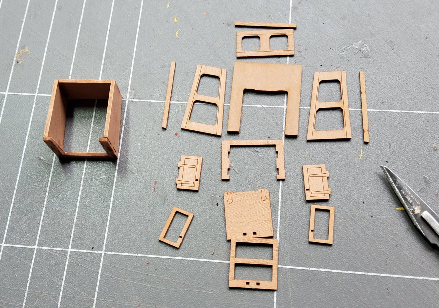
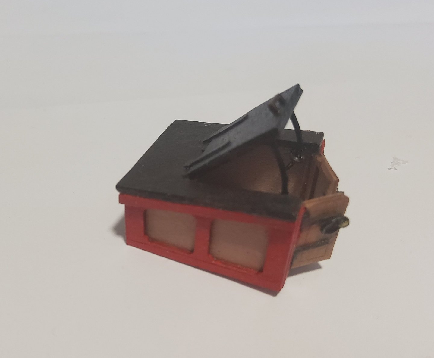
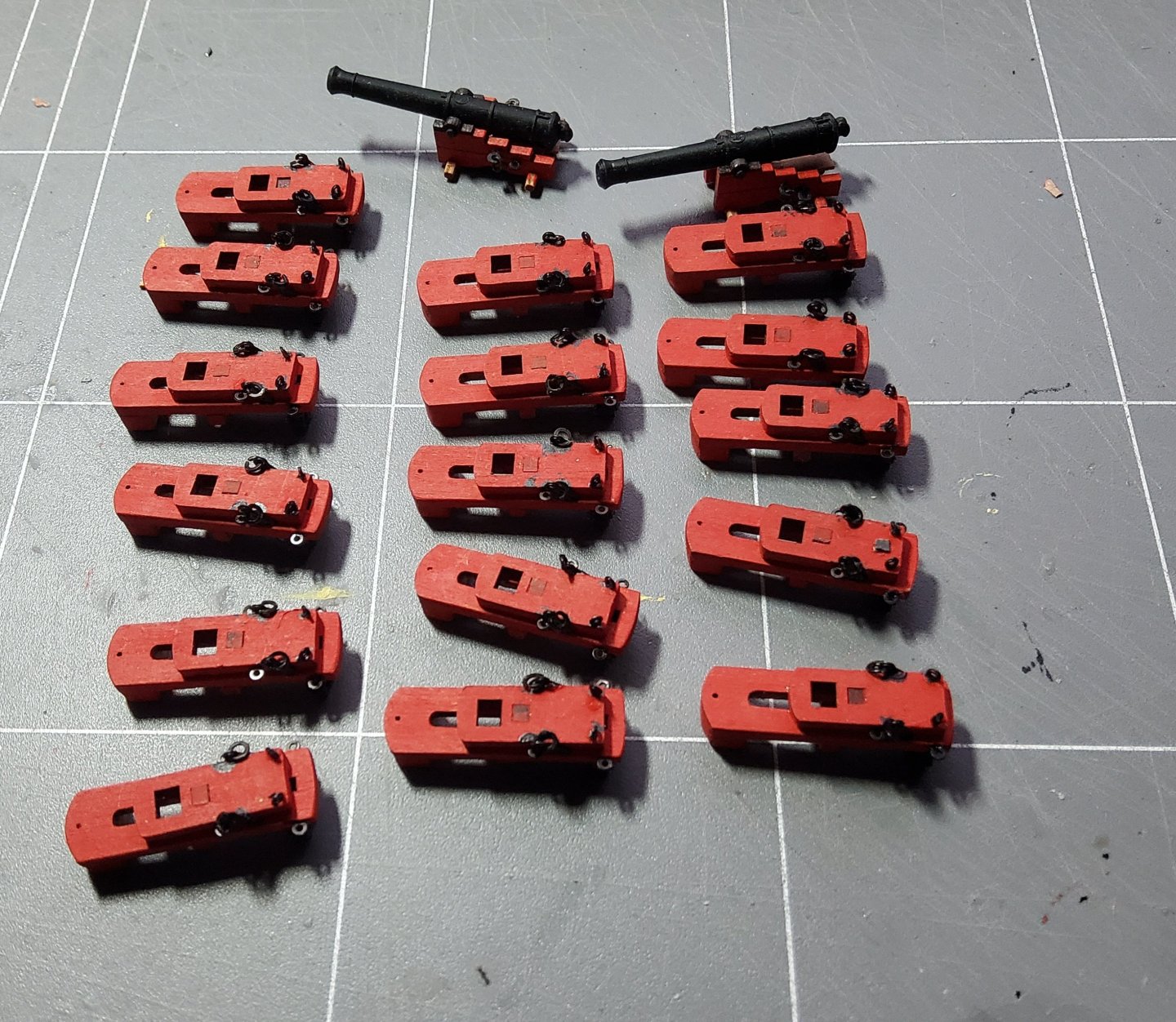
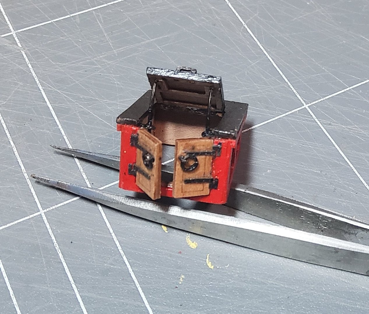
Thanks for all the likes and comments, and to those who have just stopped by. Some more progress. The first thing to do was assemble the fore platform, only four parts. It was glued together, then dryfitted, gently sanded, dryfitted etc until it was a good fit into the bow. When I was satisfied it was glued in place. The two short steps to the platform were added at this point. A longer set of steps were assembled and glued in place. The companion way fits above these, and making this proved to be a little tricky in places. The parts for it are shown below, with some pieces already glued together. The more interesting facets of this build were the two doors at the front and the hatch on top. The instructions say that these can be left closed or open. I chose to have them open. The doors were no particular problem, except for adding the hinges, provided as PE. I glued the doors in the open position then added the hinges (the handles, ring bolts, had been fixed already), but ran into some problems with the PE hinges in trying to get them to fit correctly. I finally used some of the Syren hinges I'd used previously. The hatch however needed a little more attention. As Blue Ensign said in his log, the hatch needs support in the open position. For the two supports I used some leftover PE, bent into a curve, glued to the underside of the hatch with the lower ends held in place by small eyebolts fastened to the sides of the companion way. Syren hinges were again used. The guns were assembled over several days, usually while waiting for glue or paint to dry. Assembly line. Patience is required. I didn't add Part 227, described as the "quoin" in the instructions for the long guns. Instead I replaced it with a short piece of 0.6mm fret to represent the bed of the carriage and added two separately made quoins. (The left carriage needs a paint touch up.) Finally, a word of thanks to Blue Ensign (Maurice), who continues to suggest improvements that can be made to an already superb kit (thanks Chris), some of which are obvious in my build. Cheers.

-
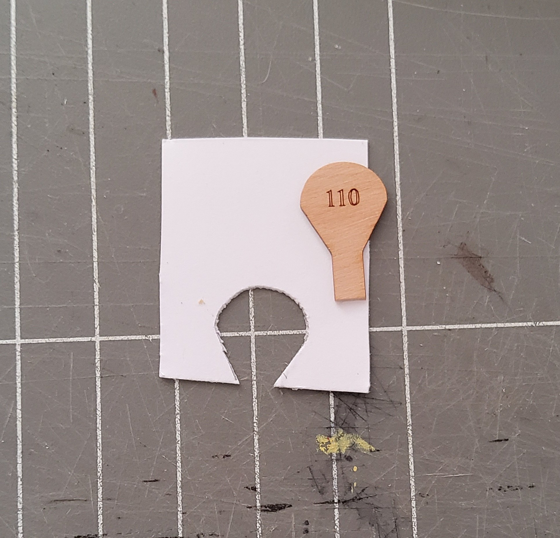
Thanks David. I had one go at trial-and-error cutting of the card, but then it dawned on me that I could use the fret as a template. Easy as.
-
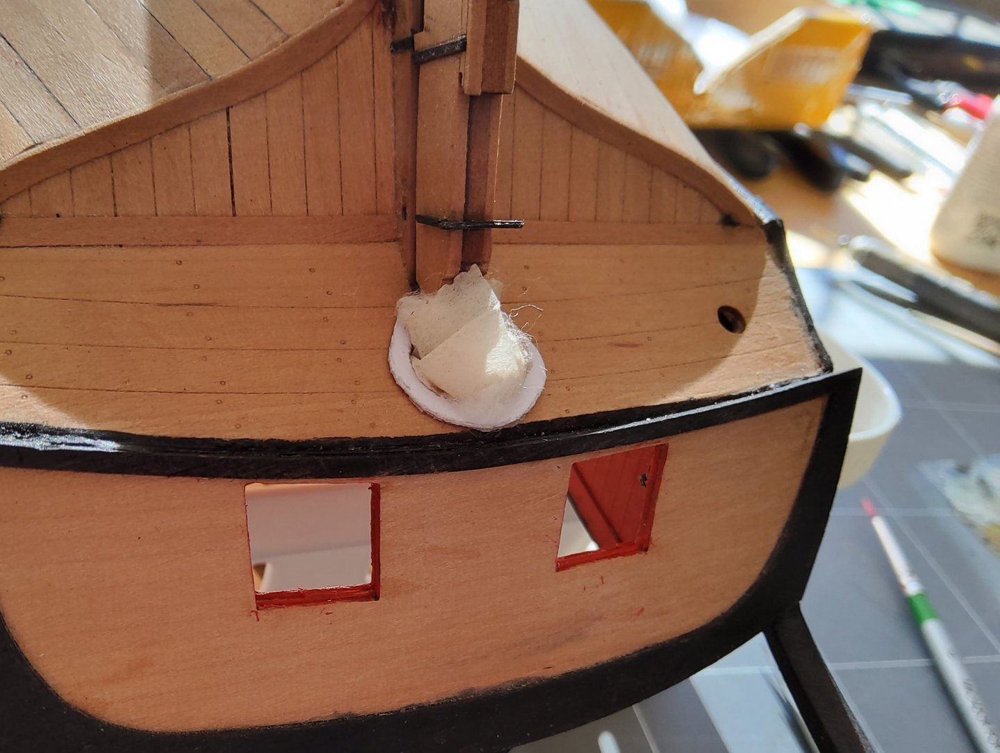
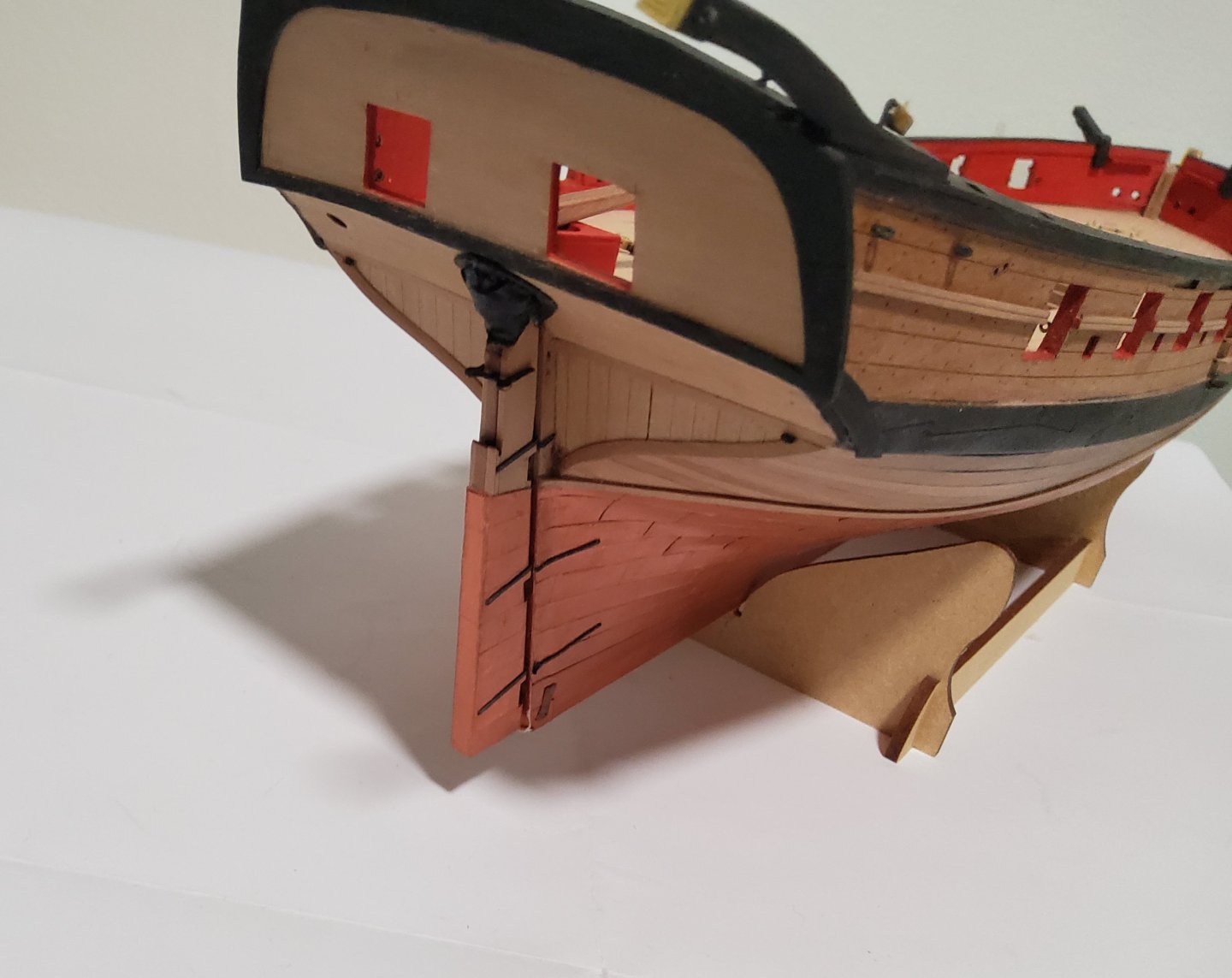
More progress, but not a lot to see. The eyepins/ringbolts were all added, with blocks seized to them where required, mostly those associated with the steering tackle. The instructions call for these latter blocks to be 3mm in size, but to me, these looked overscale and 2mm blocks were substituted. The ringbolts were made by adding a brass ring to the PE eyepins. All pin racks and cleats were glued in place. The tiller is in place but not glued. The rudder has been sitting out of harm's way, but was now fixed to the hull. Following Blue Ensign's example, a rudder coat was fashioned to fit around the rudder where it passed through the lower counter. I made one of these for my Pegasus build but couldn't remember how I'd done it so I referred to B.E's detailed description of his method in his Alert build log (here) and I more-or-less followed his method. Briefly, the coat consists of a canvas "bag" held against the rudder and the hull by a metal plate. I made the "metal" plate first, getting the inside shape by using a piece of the fret that had contained the lower counter, and then simply eyeballing the outer edge to give me a horseshoe shaped plate. Card was used. I had no fine material for the bag so used surgical tape instead. The plate and the tape were glued to the hull, leaving the tape baggy enough to stuff some cotton wool into it and then moulded it to suggest a bag. Once satisfied with this, I painted the coat with a mix of black water-based acrylic and PVA. Card and the piece of fret used to get the inner shape of the plate. The partly stuffed bag. Cheers


-
OK, time to 'fess up. I made a serious mistake that can't be corrected 🤒😬. If it had been two pieces of wood I could have de-glued them, but once two pieces of card are glued together, that's the way they will stay. I had however, photocopied the sheets from the kit when it arrived, and I have some 1mm material i can use for laminating, so all is not lost. There will however be a brief interval till I catch up with myself 🥴. Cheers
-
Thank you for the kind comment François. Yes it is a flower. Cheers

-
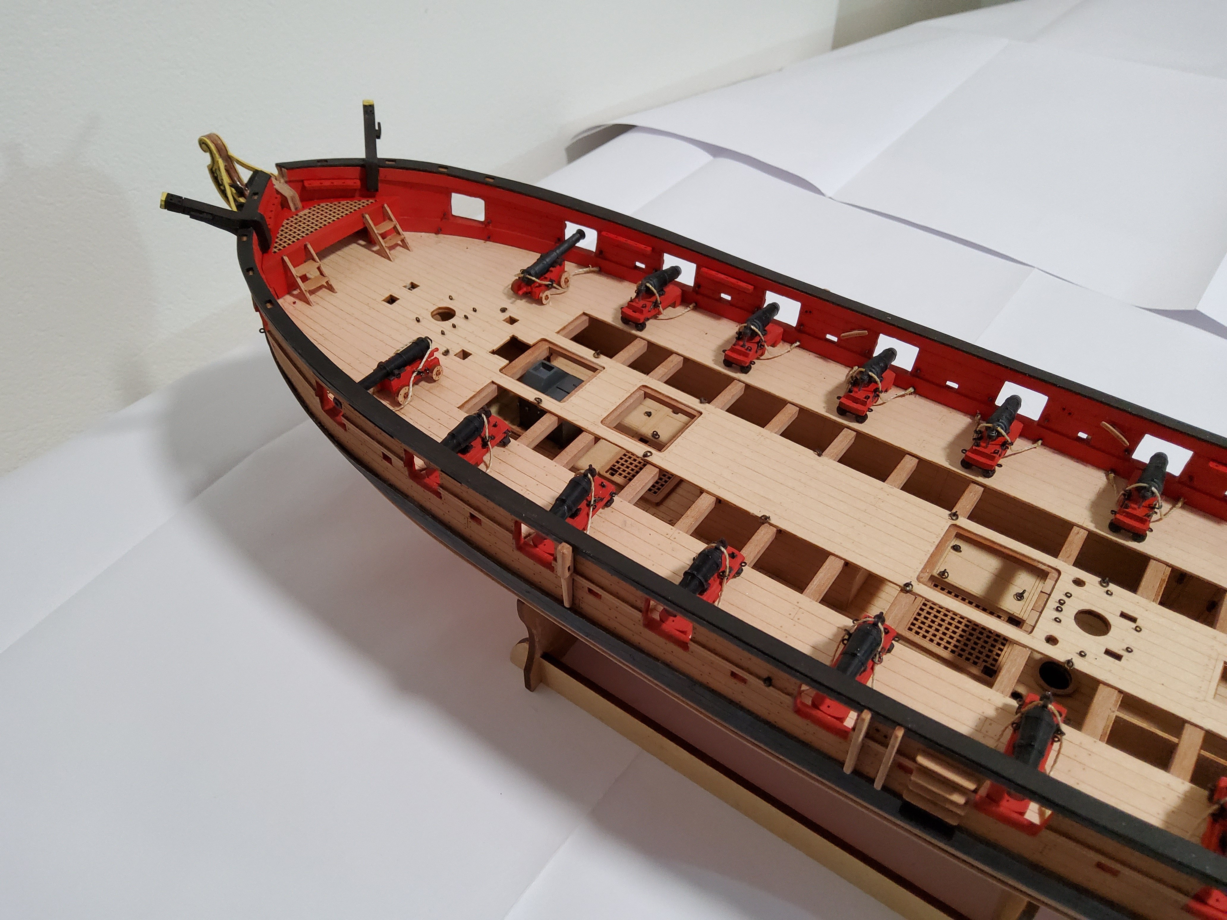
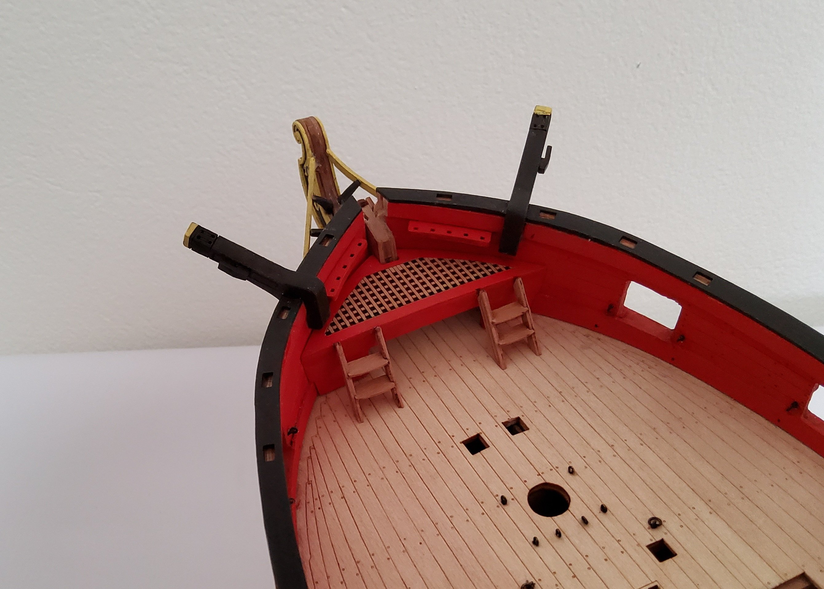
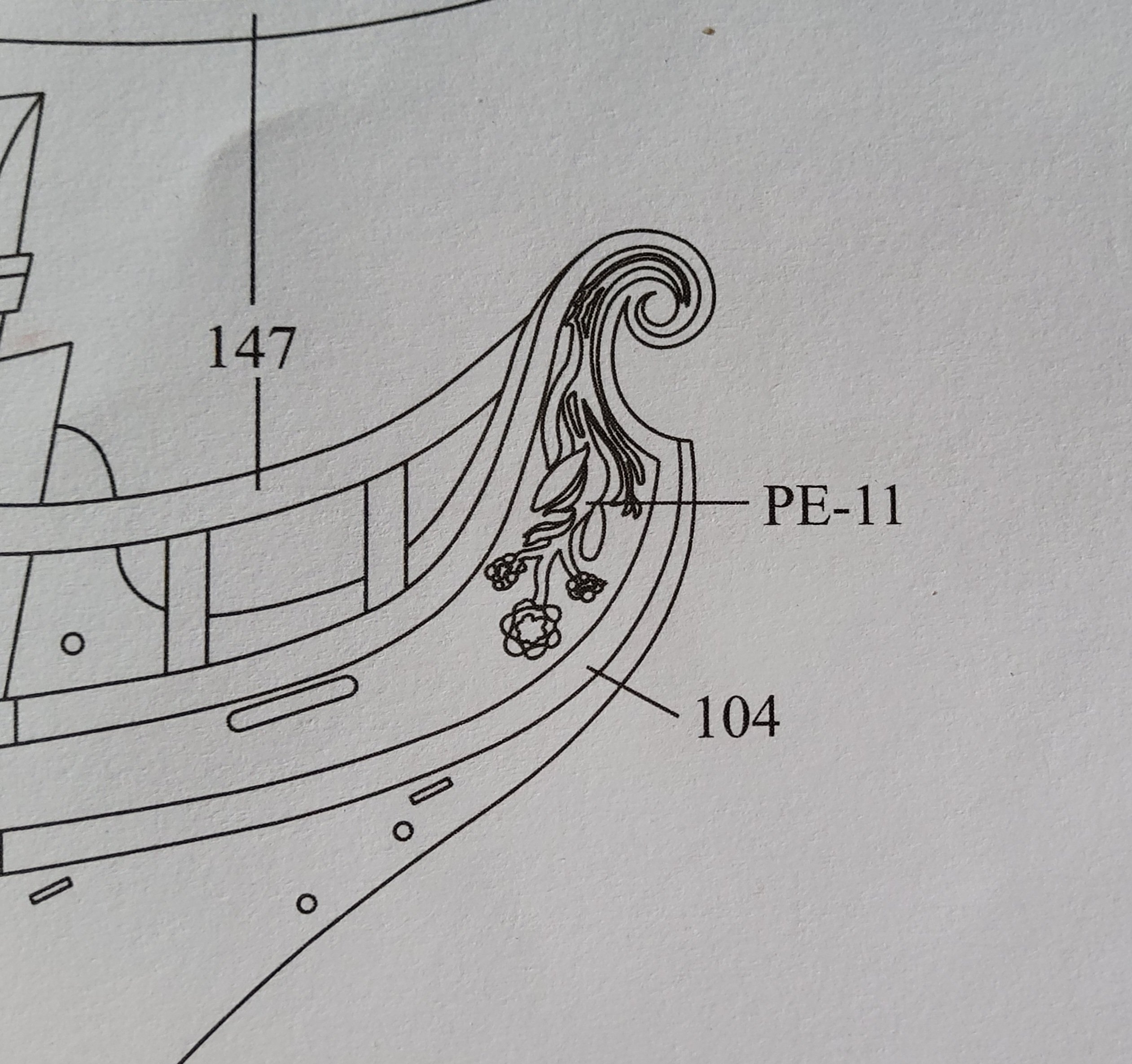
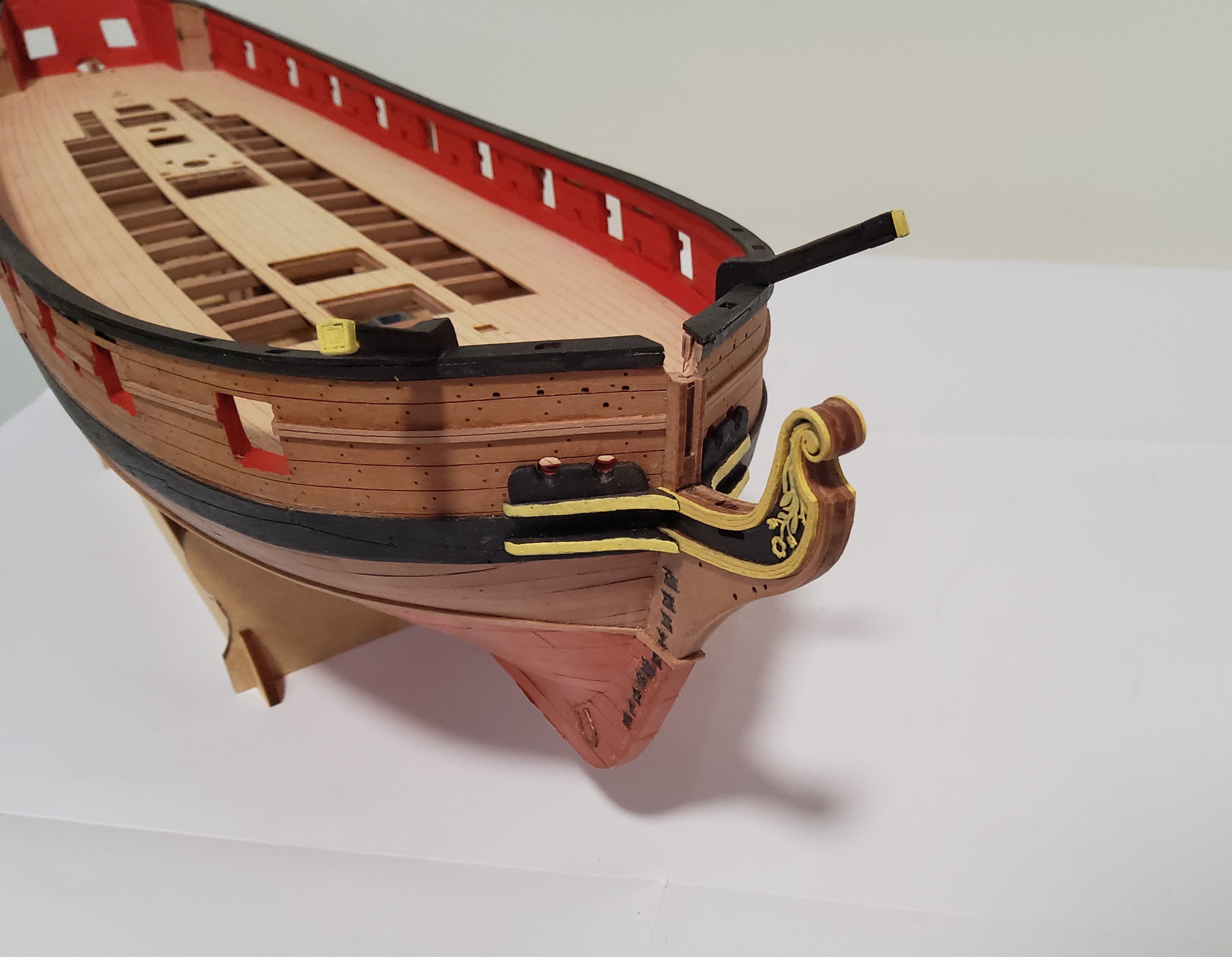
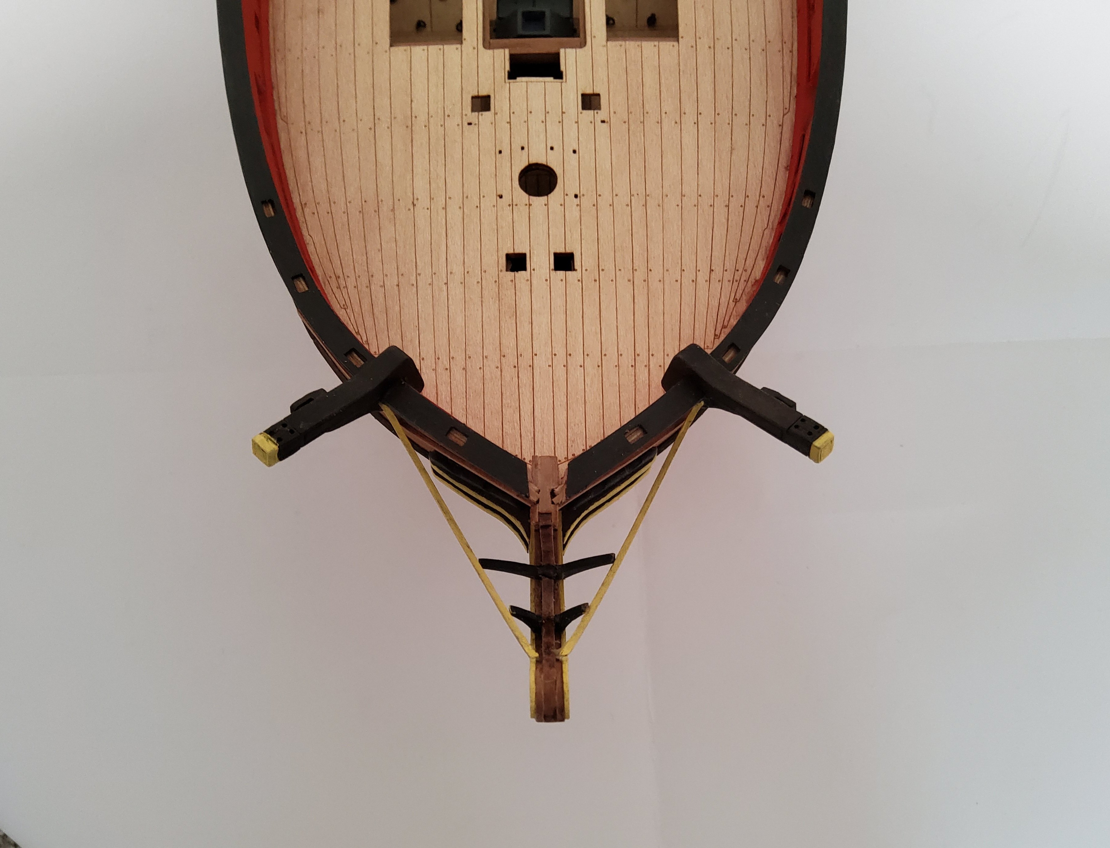
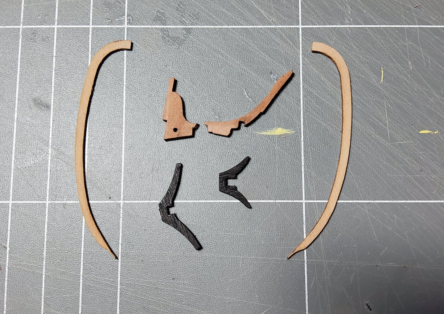
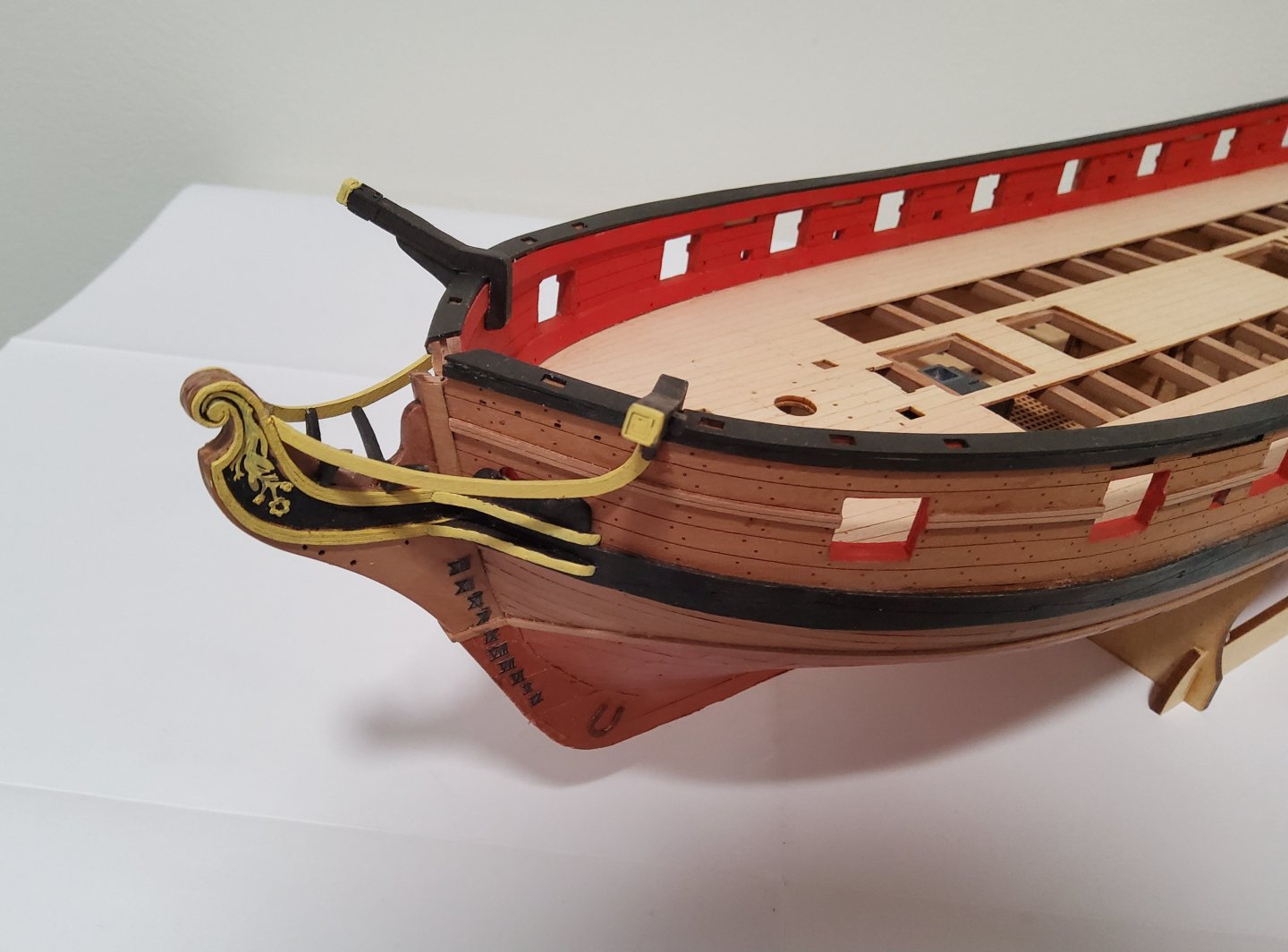
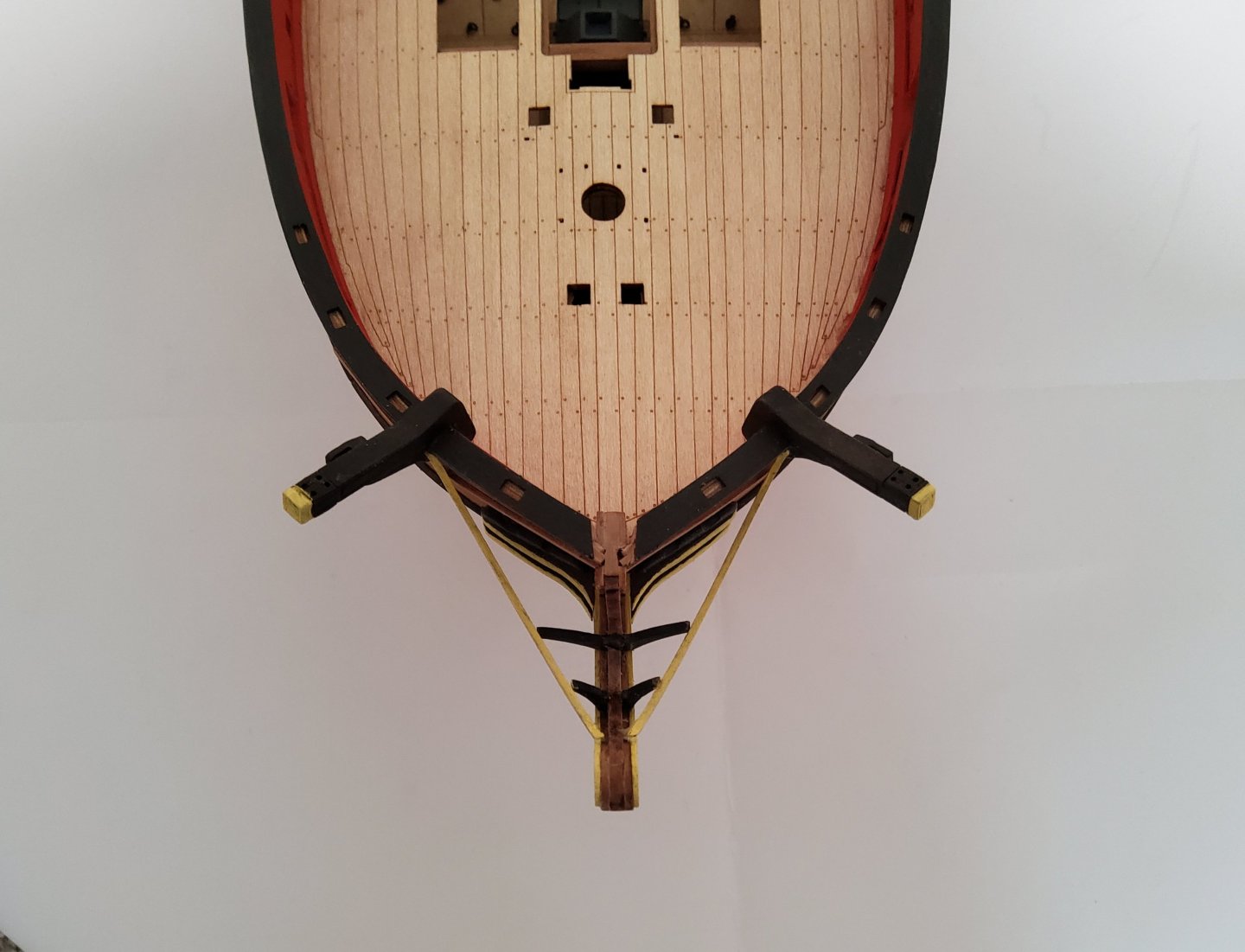
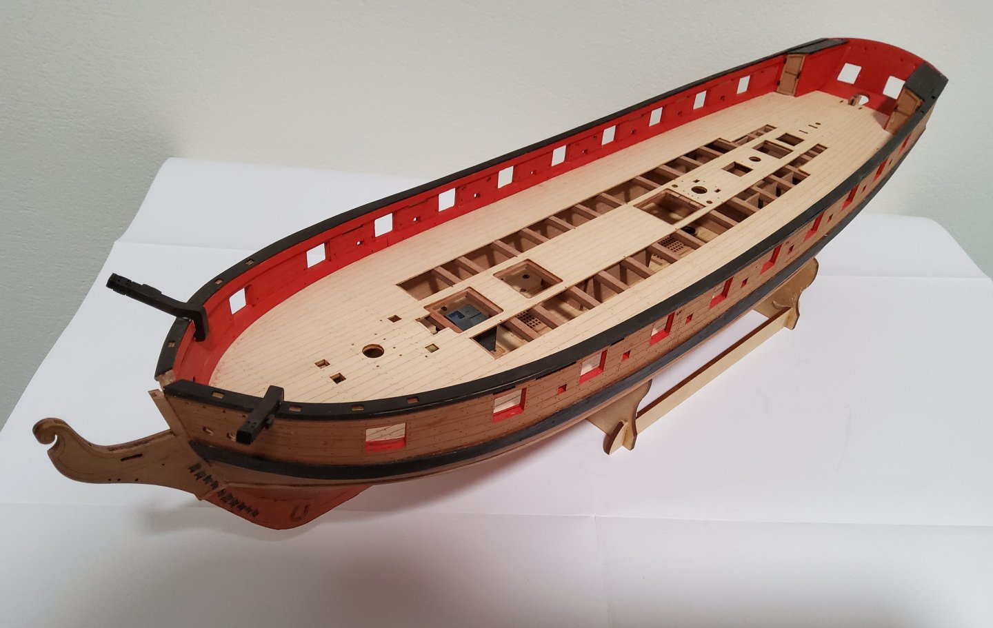
Some further progress. The hair brackets and the PE decoration that fits between the brackets were added to the prow. The upper and lower cheeks were added as was the hawse bolster. The brackets were very delicate and required careful handling, but fitted perfectly. The cheeks needed some sanding to get them to fit as they should. The bolsters needed quite a lot of sanding before they matched the existing hawse holes. The next bits to add were the prow knee and the "V" brackets that support the head rails. Chris very kindly included two sets of these (other than the knee) in case some of these rather delicate pieces were broken. Murphy's law was then triggered and the only piece I broke was the non-dupicated one. There was no chance of gluing the two pieces together, so each part was separately added to the prow along with its "V" bracket. There is a slight misalignment, but you need to know it's there to see it. The head rails were then added. And the davits have glued in place at the stern. Cheers

-
Found them.
-
Chris, You've not mentioned doors to the nose wheel well - are there any? One diagram does show a door but I can't find any other reference. Cheers, Richard
-
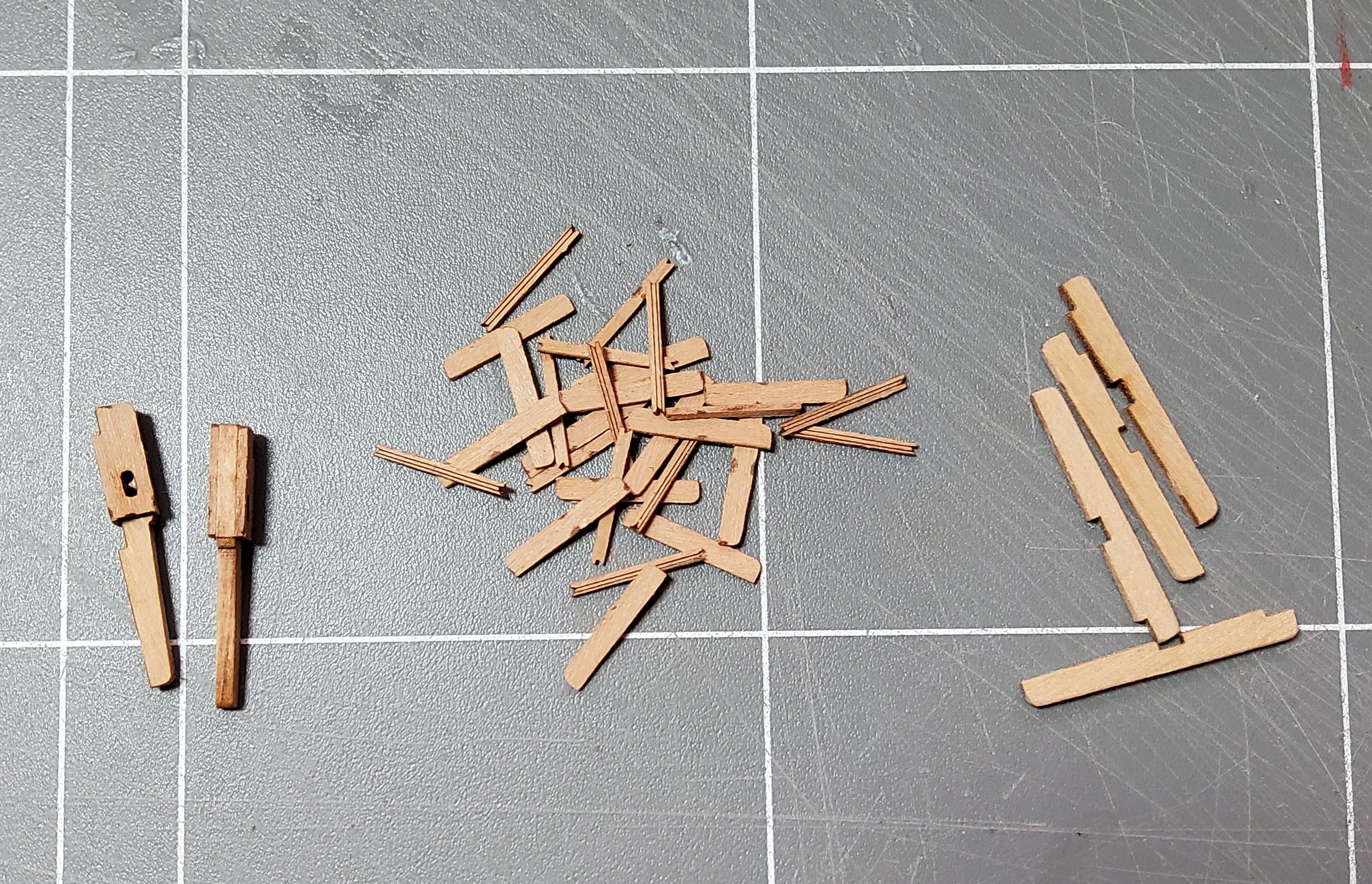
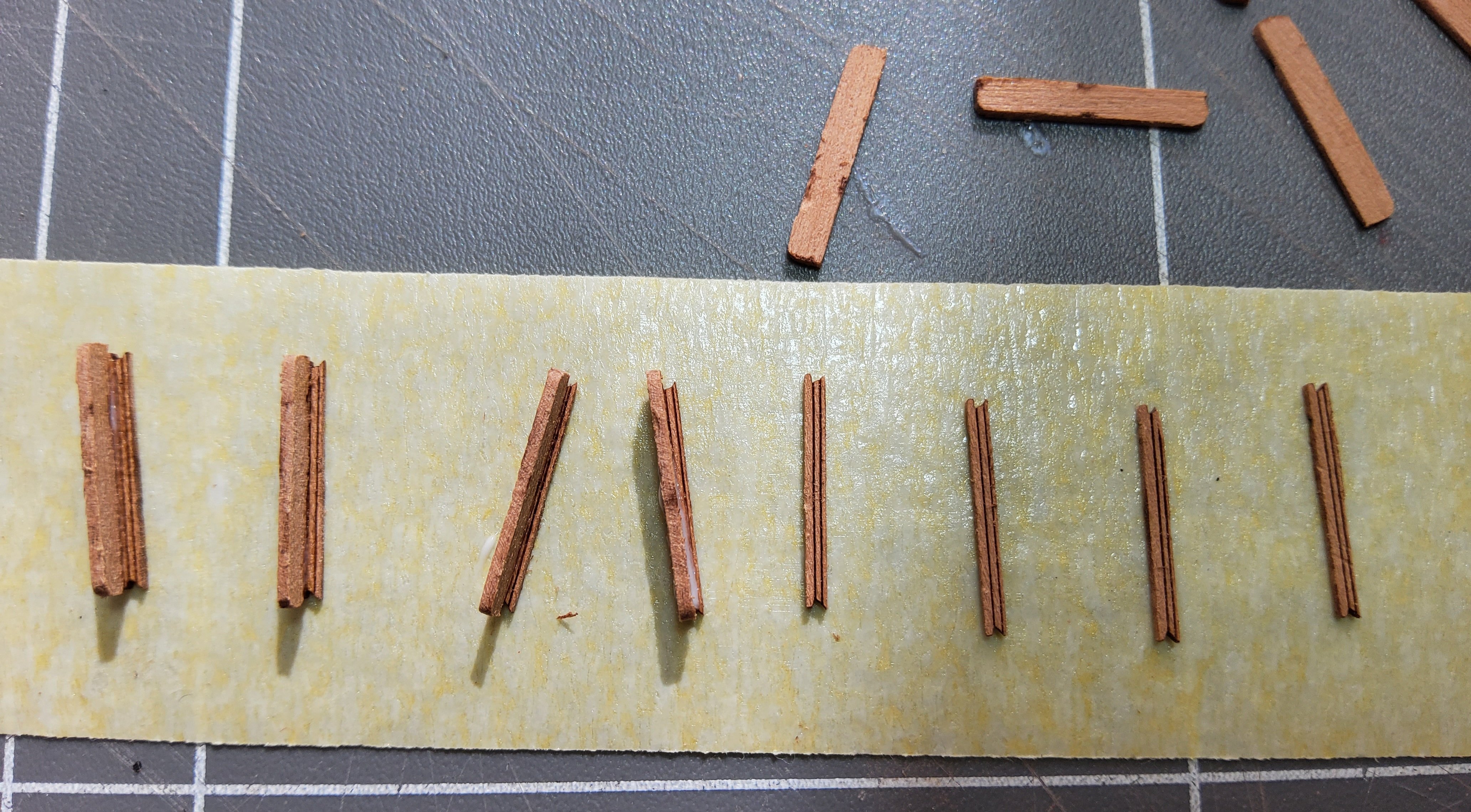
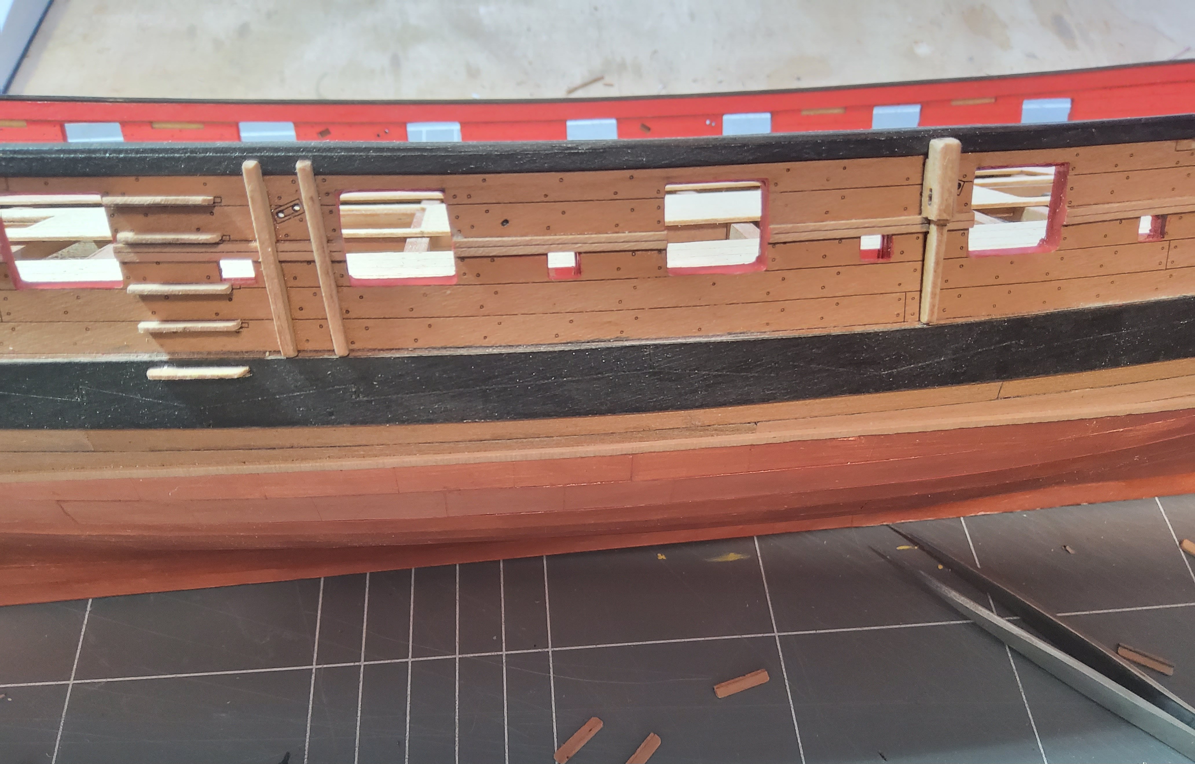
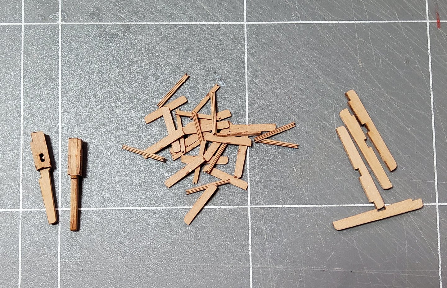
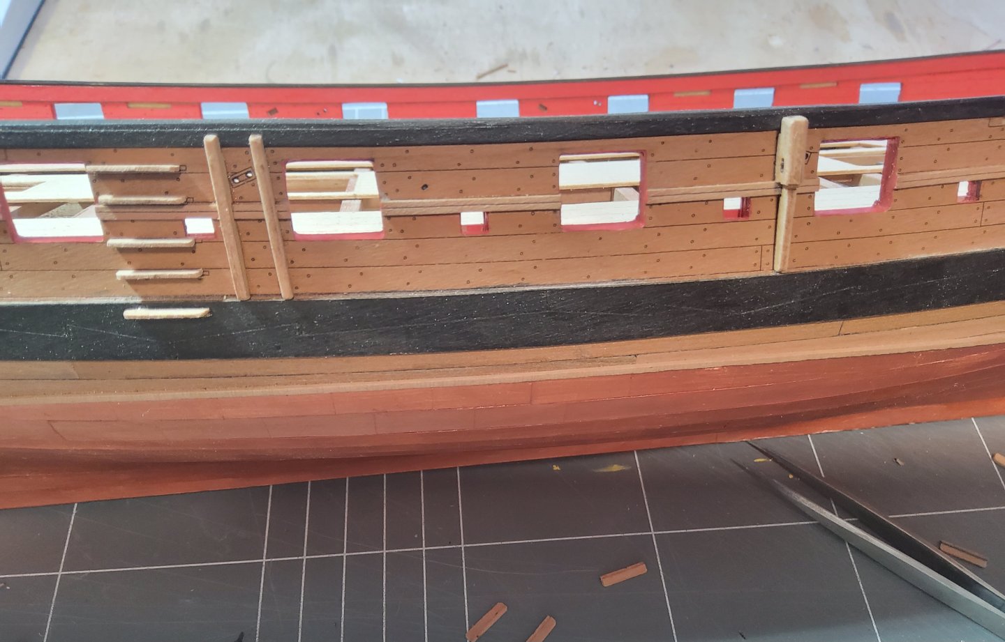
Thanks for all the likes, and to those who just stop by. A short update. The chesstrees, fenders and steps were added to the hull. The pieces are shown in the following photo, the chesstrees on the left, the fenders on the right and the two pieces (treads and risers) for the steps in the middle. To assemble the steps, the risers were laid out on a strip of masking tape, sticky side up, and the treads were then glued to them. There are four completed steps on the left. The chesstrees and the fenders were rounded slightly on their outside edges to improve their appearance, and needed a slight touch with a diamond file to let them fit close against the hull. The lowermost step will be painted to match the wale. Cheers

-
They're raised, they came as PE pieces.
-
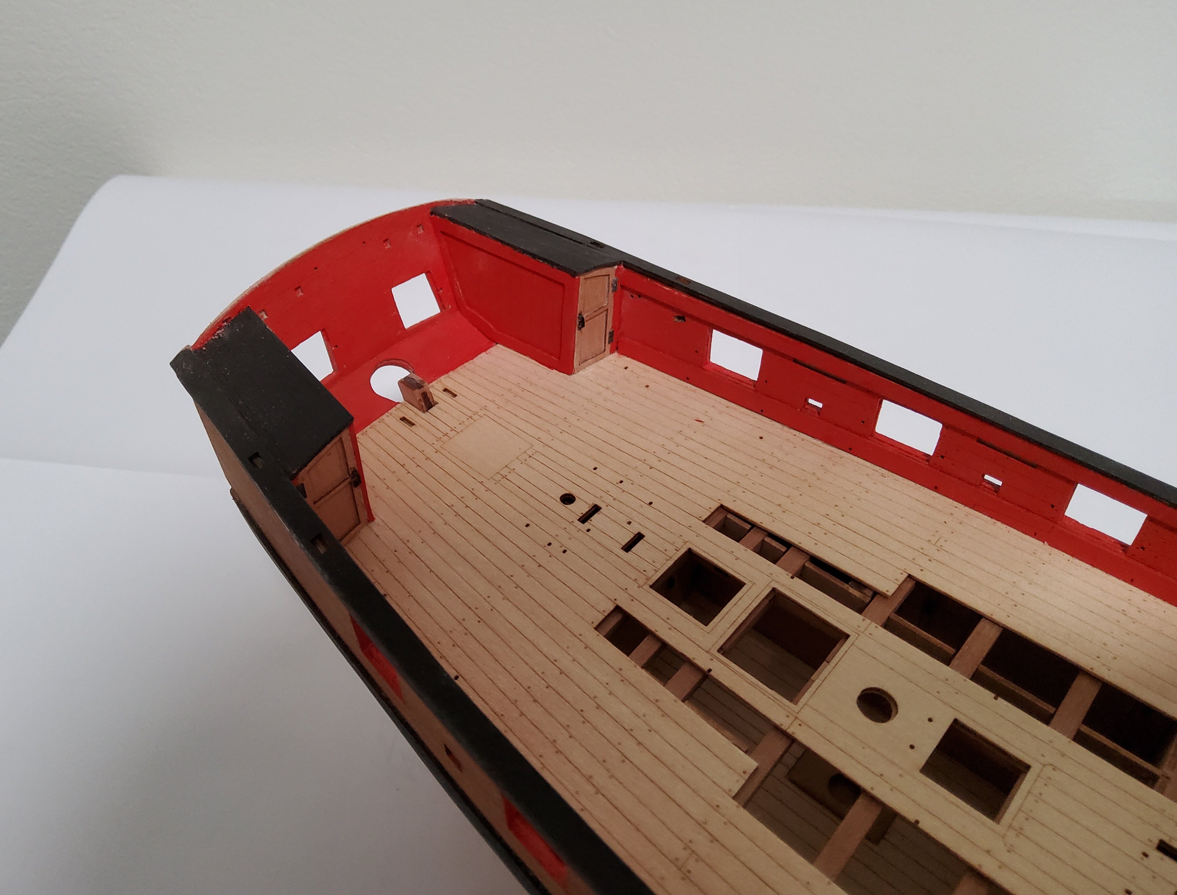
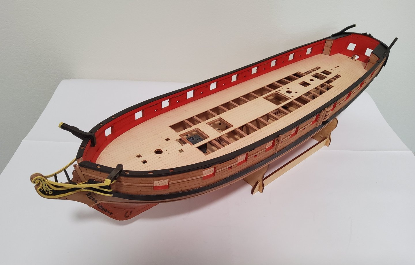
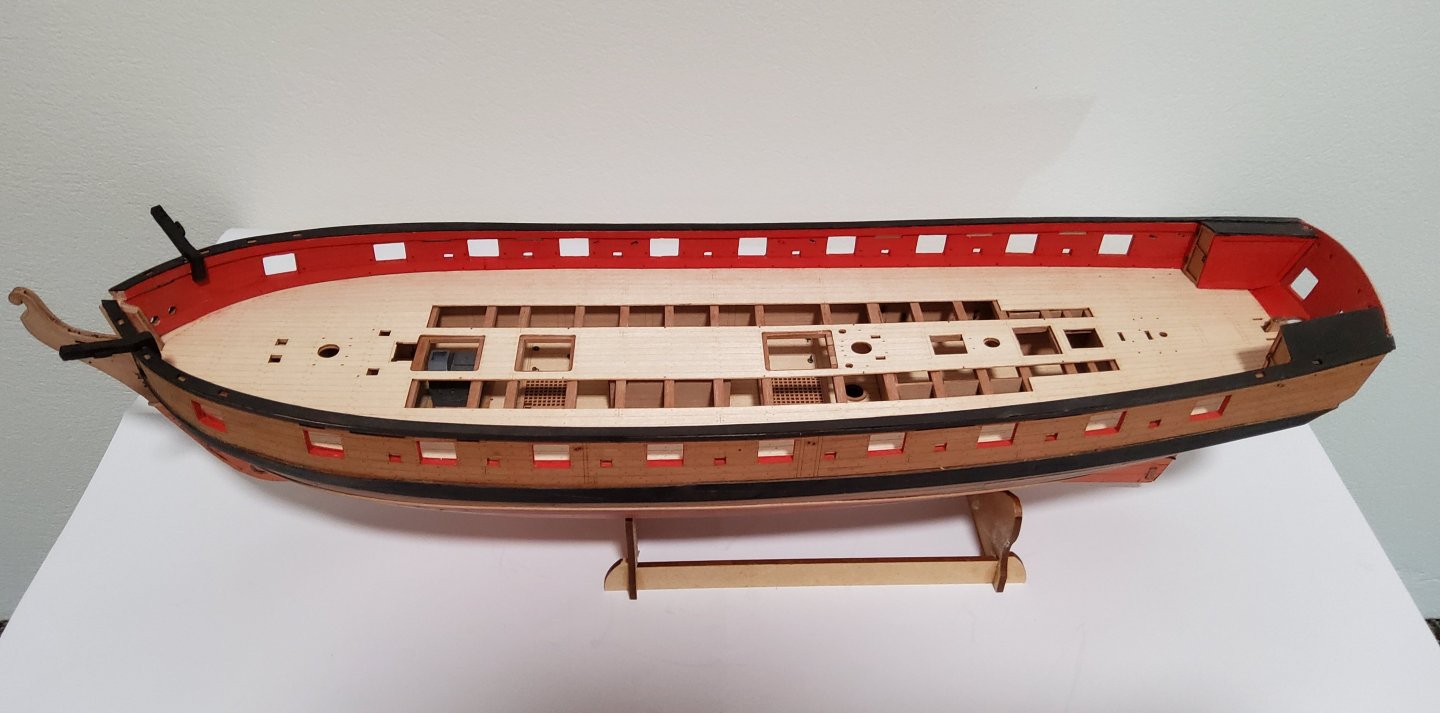
The stern cabins. These were a bit fiddly to do, needing dry-fitting, sanding and repeating until the fit was satisfactory Various rails were added - top and bottom of the inner bulwarks, the caprail and the one immediately under it and the decorative moulding that crosses the gunports. The catheads were added, as were the side counter timbers. Nothing really to say about these additions, all were easy enough. The gunport sills were painted red, but before doing so, wood filler was applied to them to hide the laminated appearance. Cheers


-
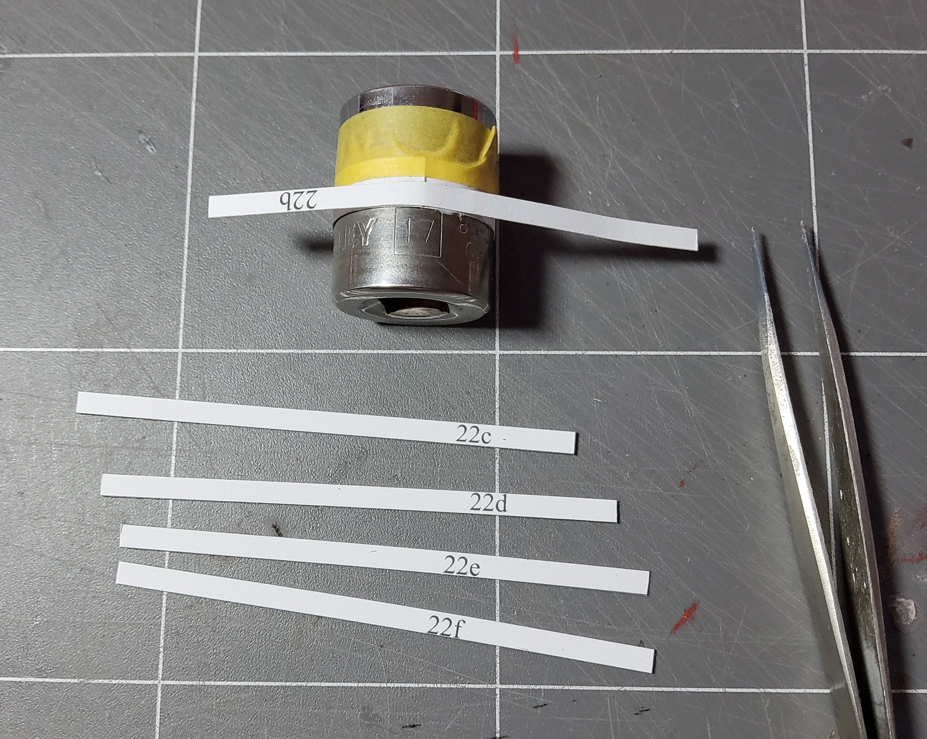
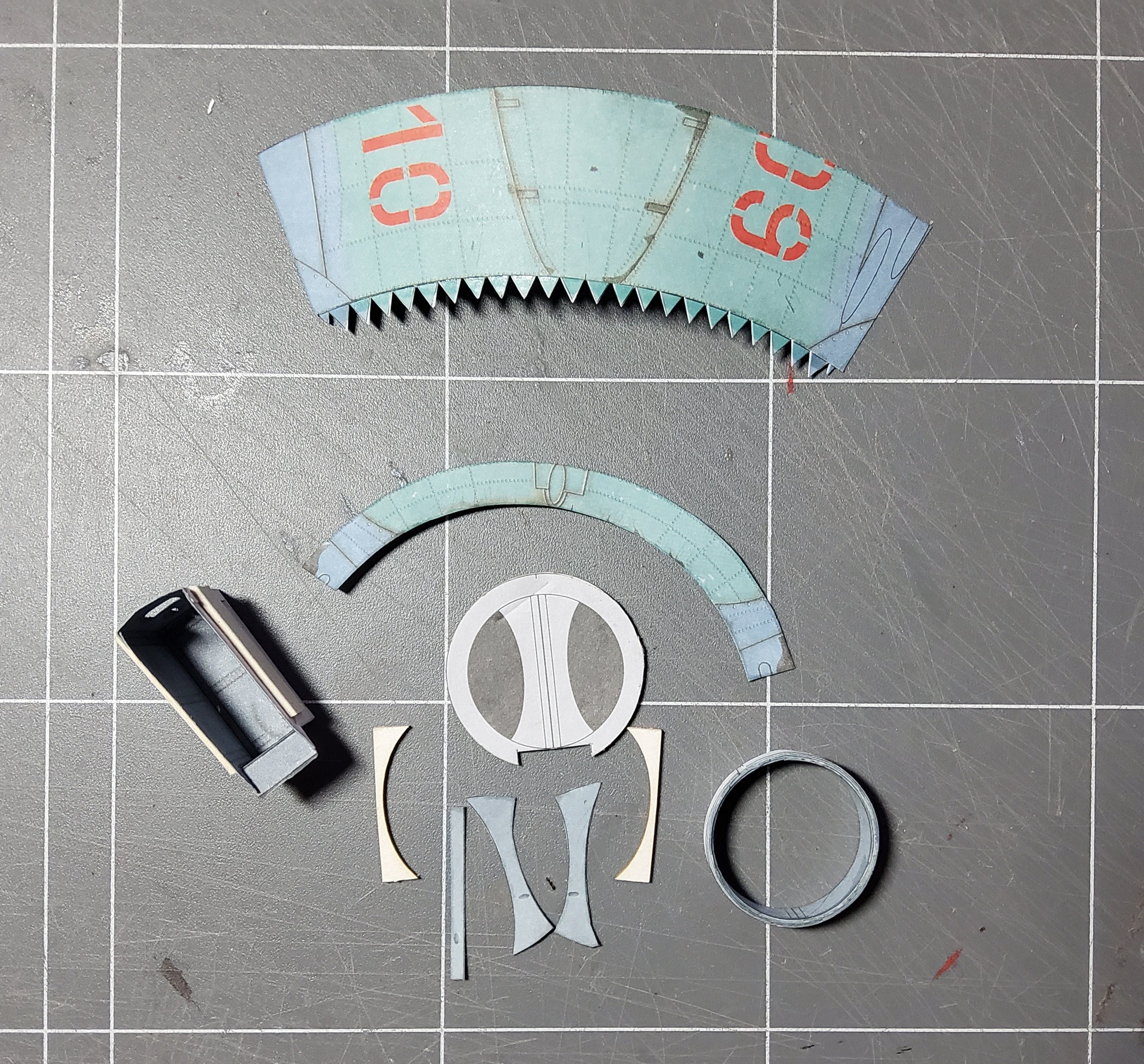
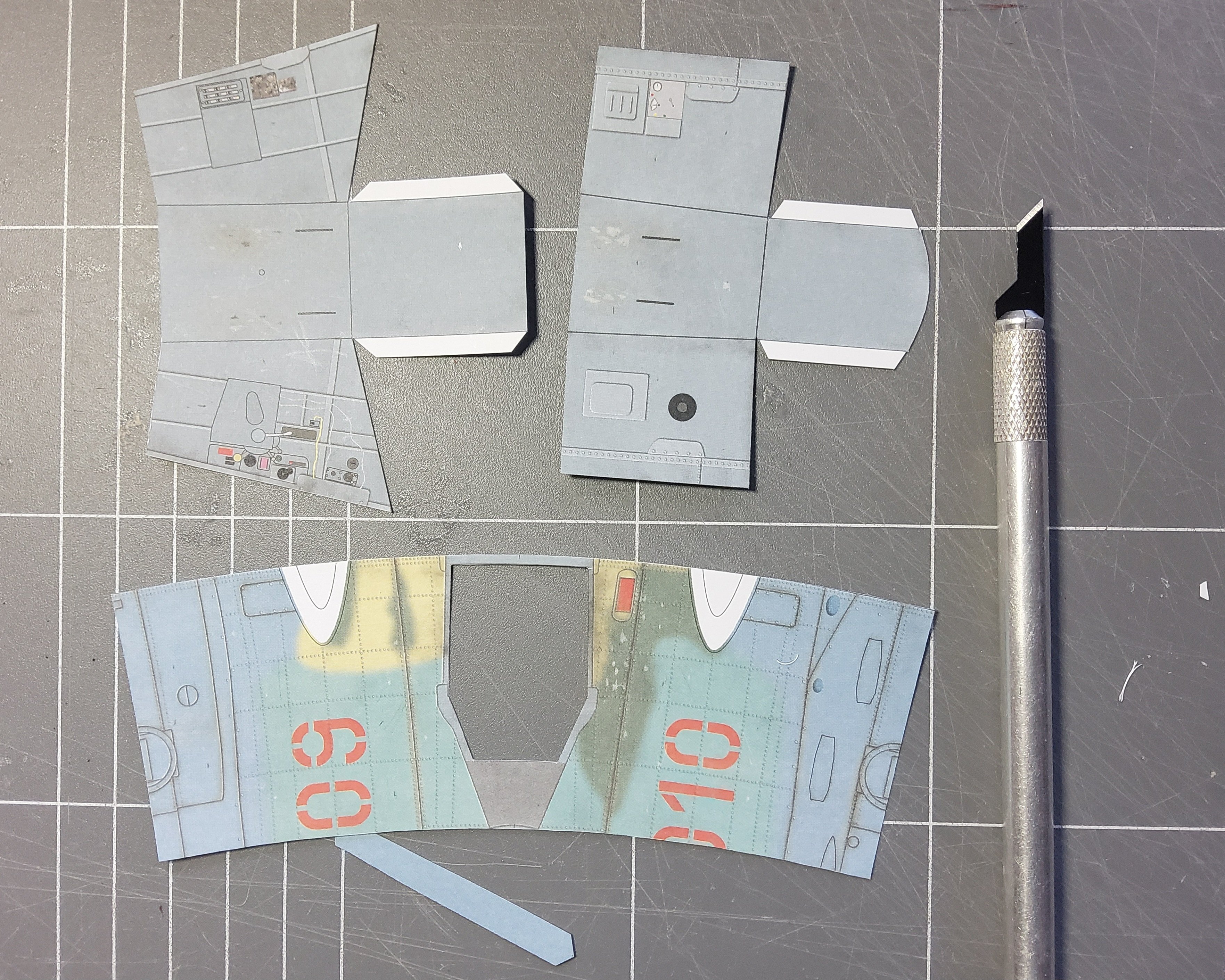
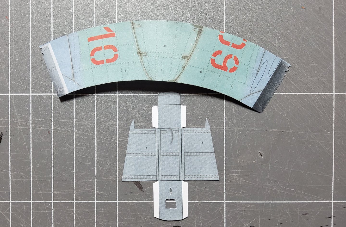
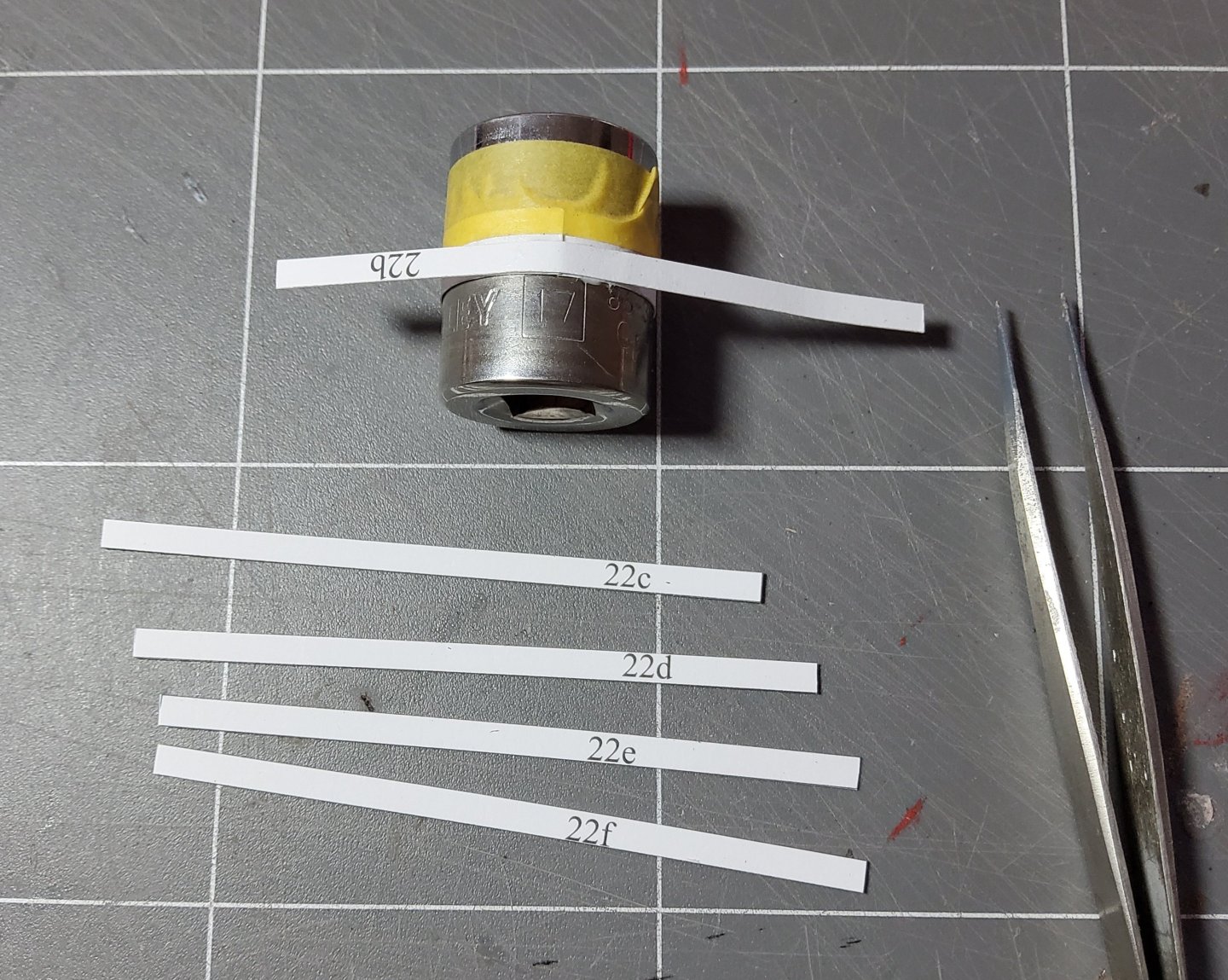
Some more work on the MiG. The next forward conic section was cut out, as was the piece for the front wheel well. Then I formed part of the air intake. This involved wrapping six strips around a mandrel, with each subsequent strip lying directly on top of the previous one. Except for the first strip. This was a colour printed strip that had to finish up completely circular with the ends butt joined. Whilst hunting around for a suitable mandrel, I finally realised that a 17mm socket spanner was exactly right. A few other pieces for the forward section and the air intake and all are shown below ready for assembly. That's all for now. Cheers
-
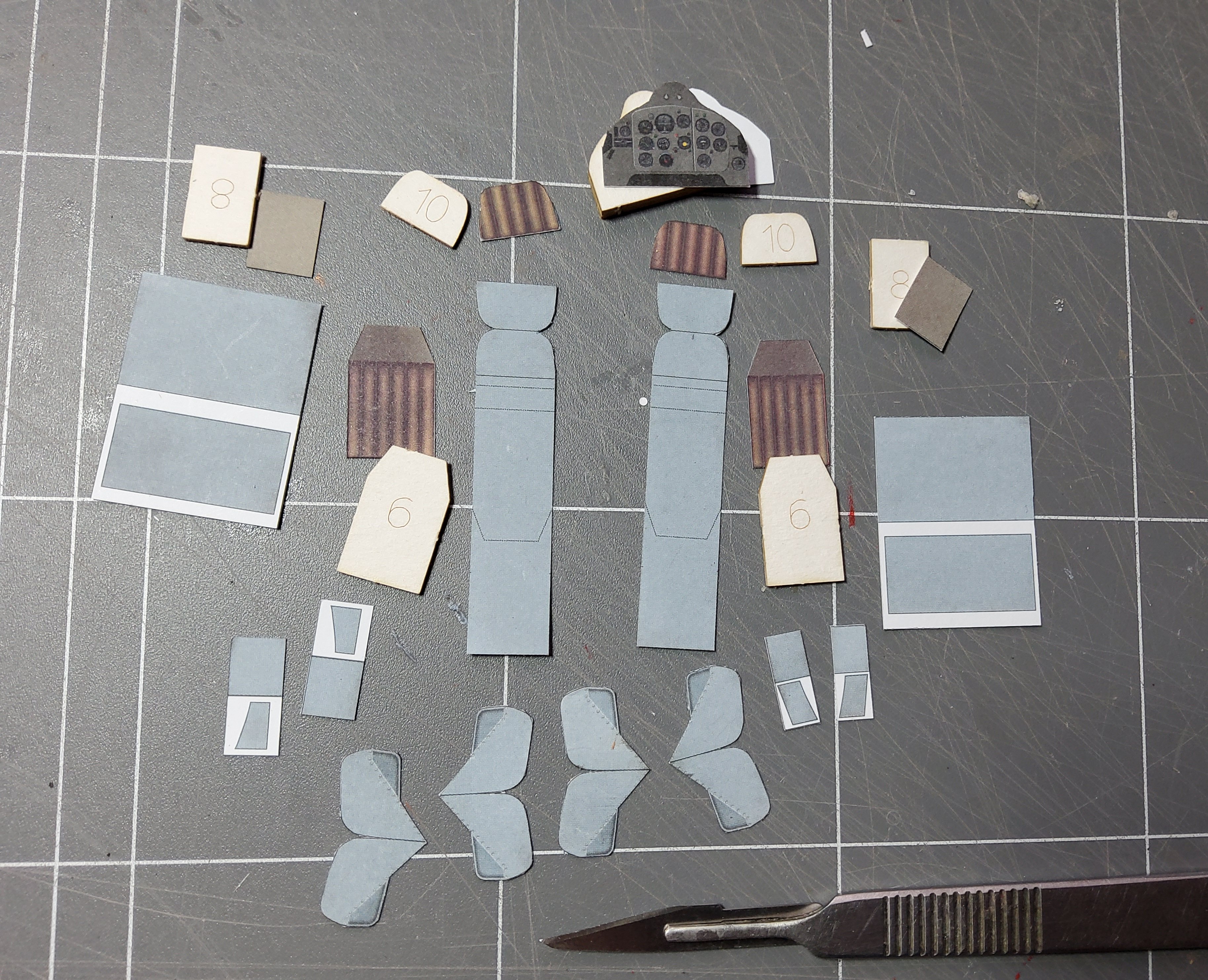
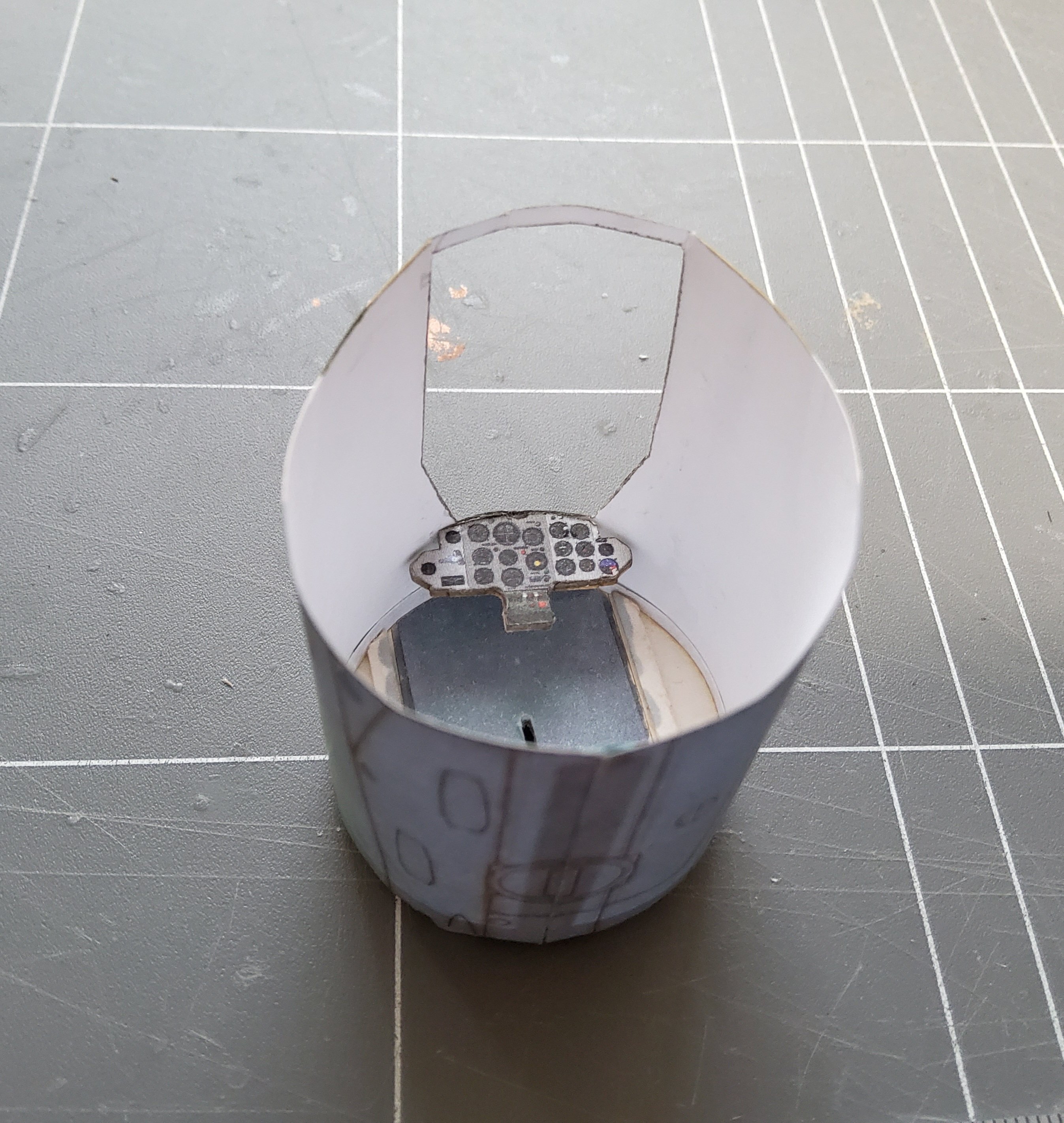
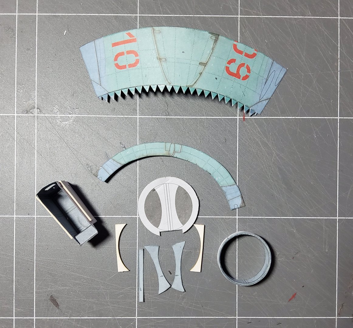
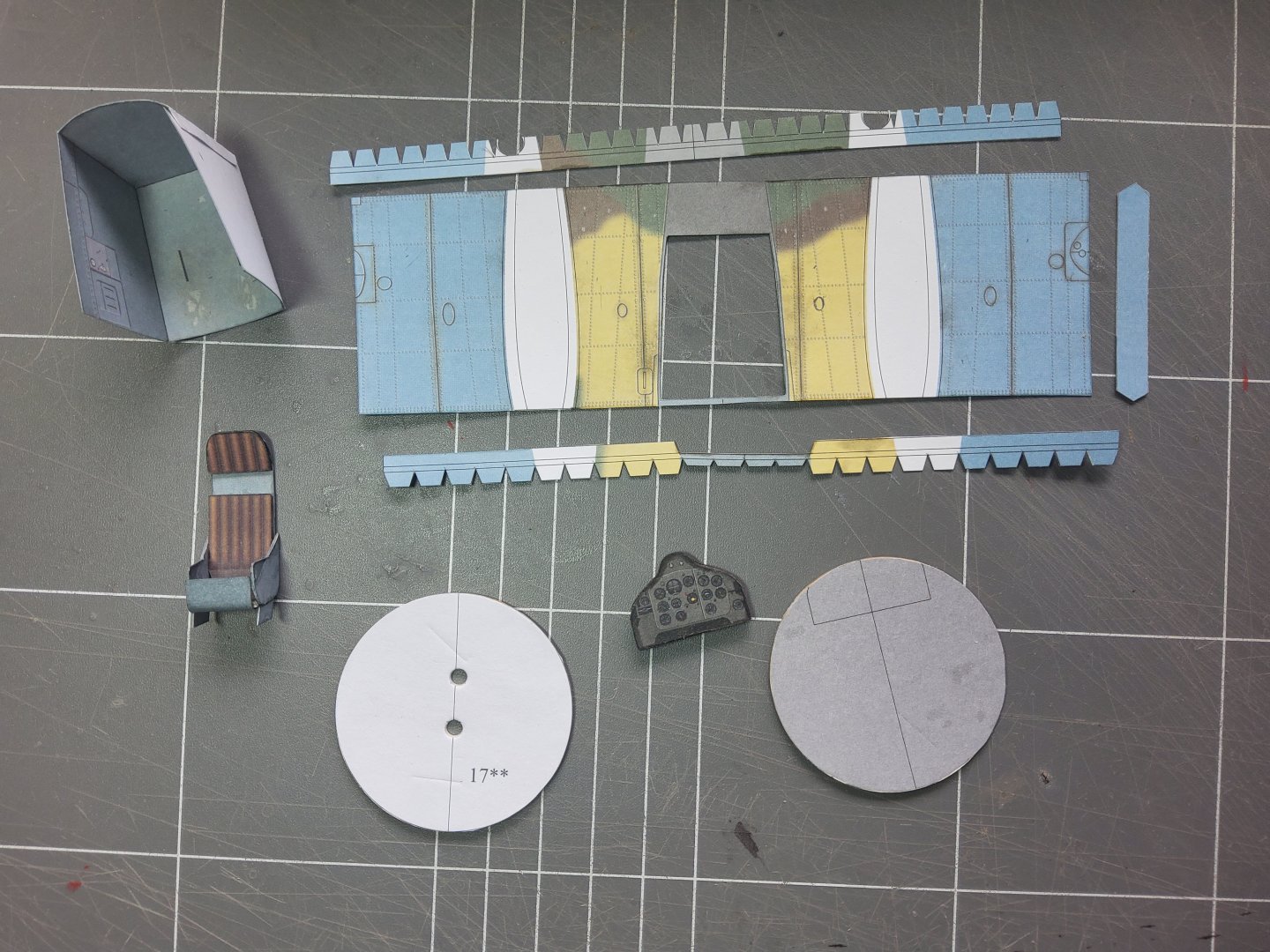
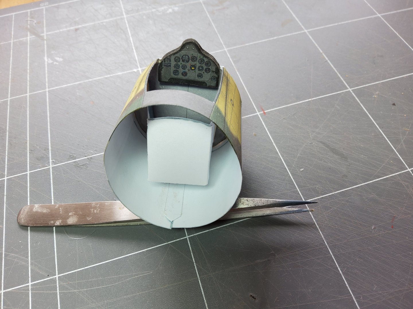
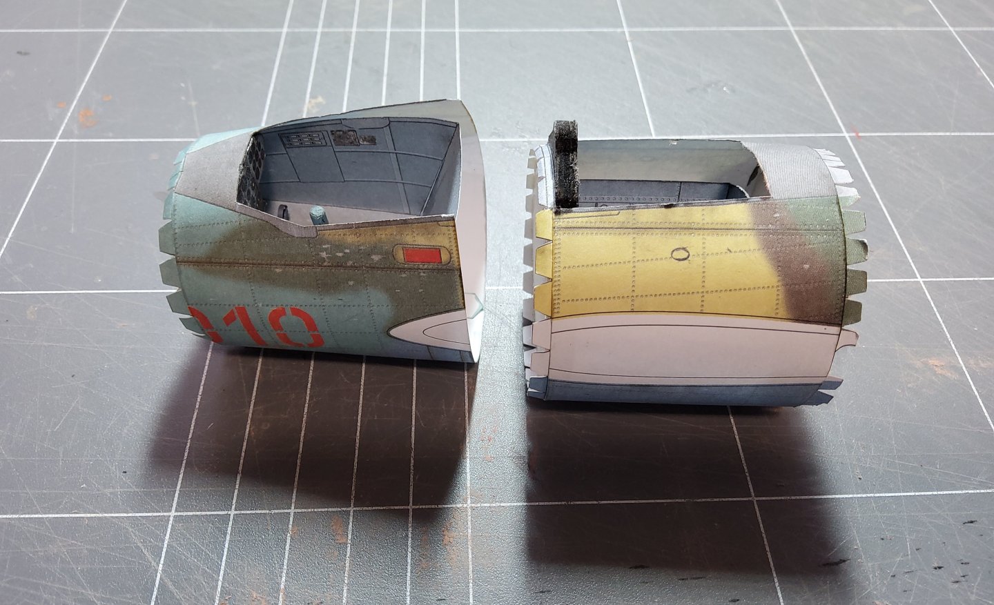
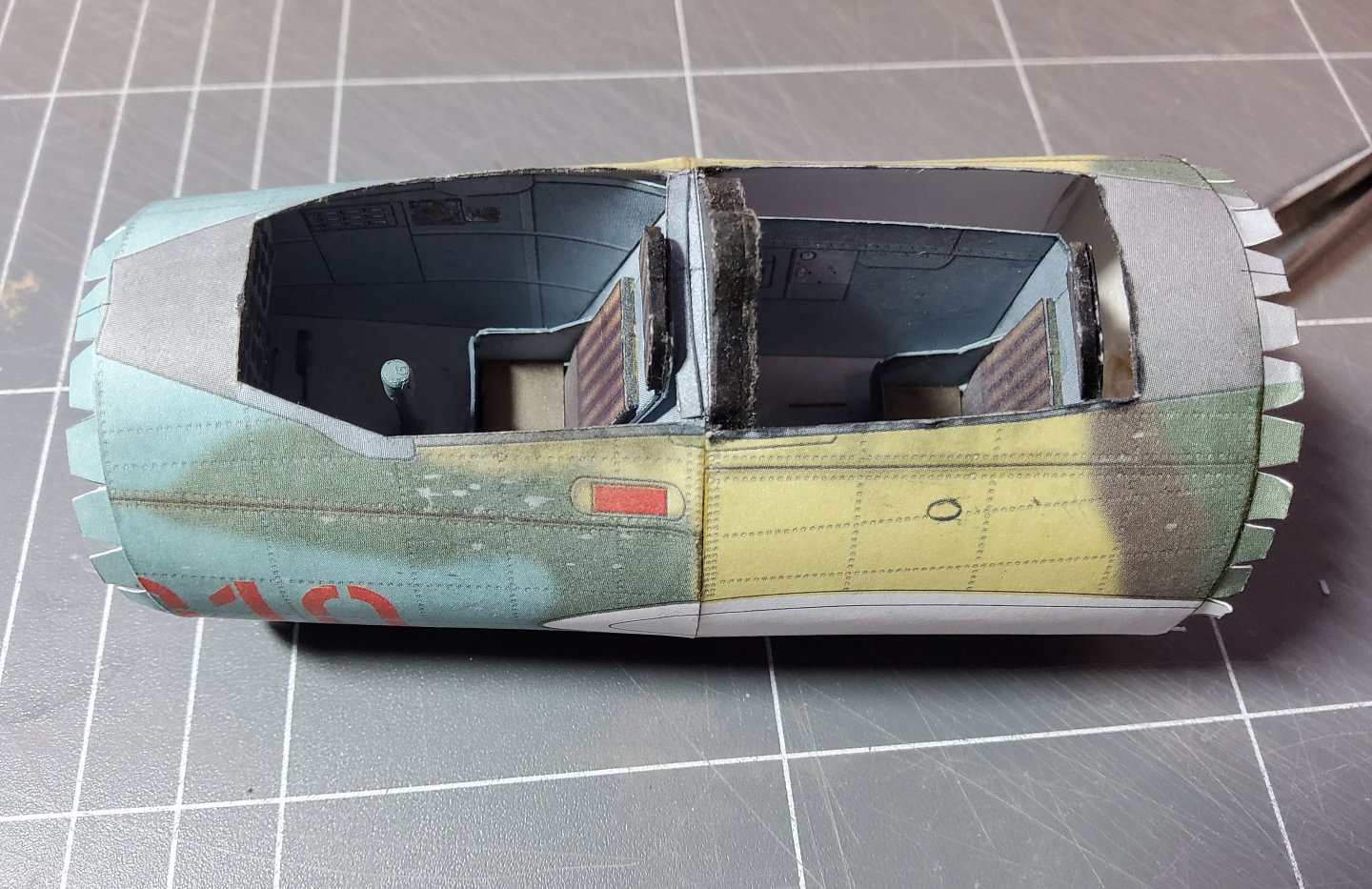
The next thing to do is assemble the parts for the second cockpit, these are shown in the photo. The rear bulkhead has had two holes punched in it (Chris' suggestion) to help with inserting this into the fuselage skin, as access is cut-off once the skin and forward bulkhead are glued together. Suitable pliers could then be used to grip the bulkhead. The forward bulkhead, rear tub, instrument panel and skin glued together. The rear bulkhead and joiner strip have yet to be added. The rear bulkhead took some effort to get in place. Dry fit, sand the rim gently, repeat. The two holes took a battering, but finally the bulkhead was seated and glued. The two completed (less seats) fuselage sections ready for joining. Could be interesting. It was a very pleasant surprise to find that there was no problem at all to join these two. I didn't need to use any of those magical words we sometimes have to rely on 😁. Cheers
- 28 replies
-
- 10
-

-
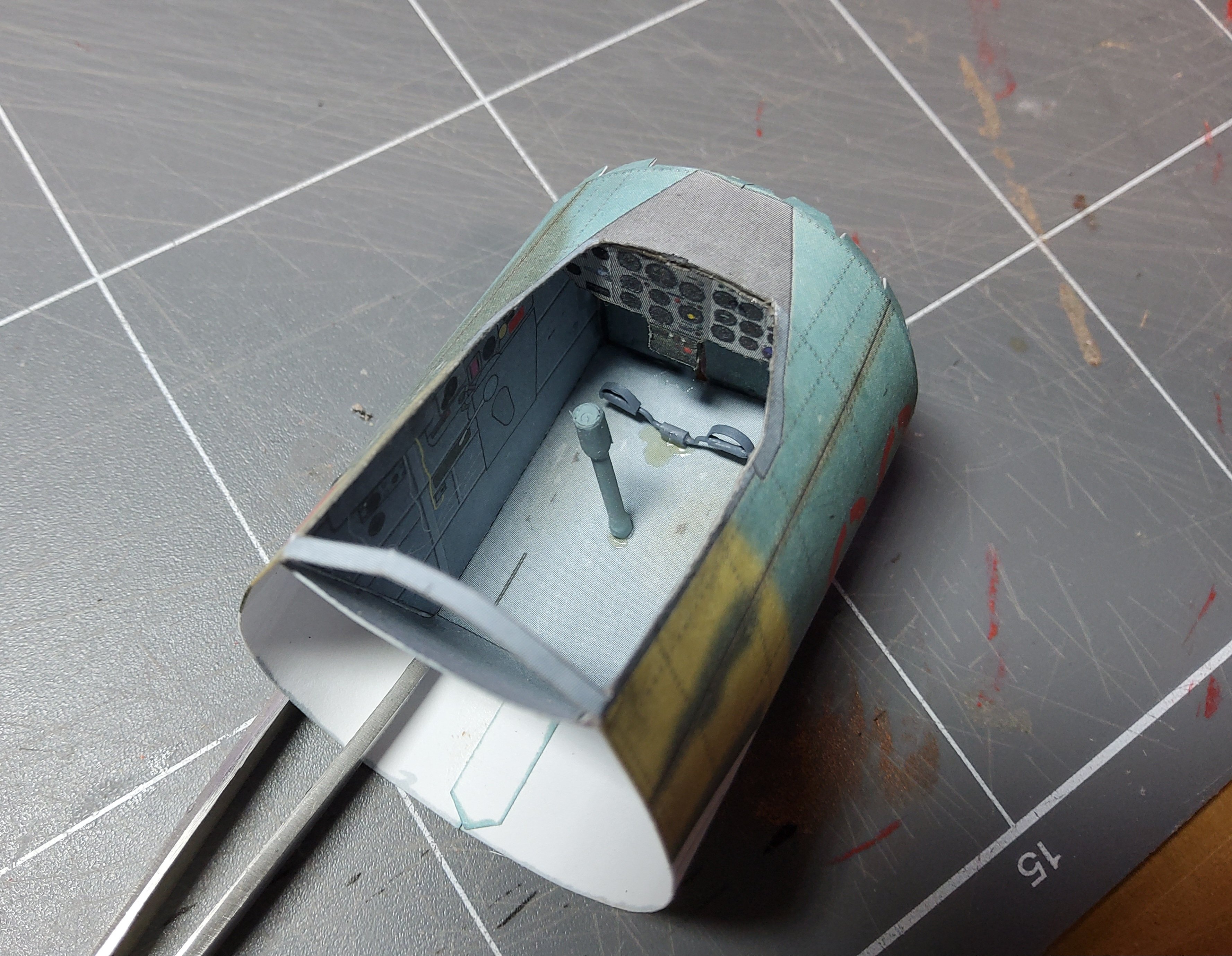
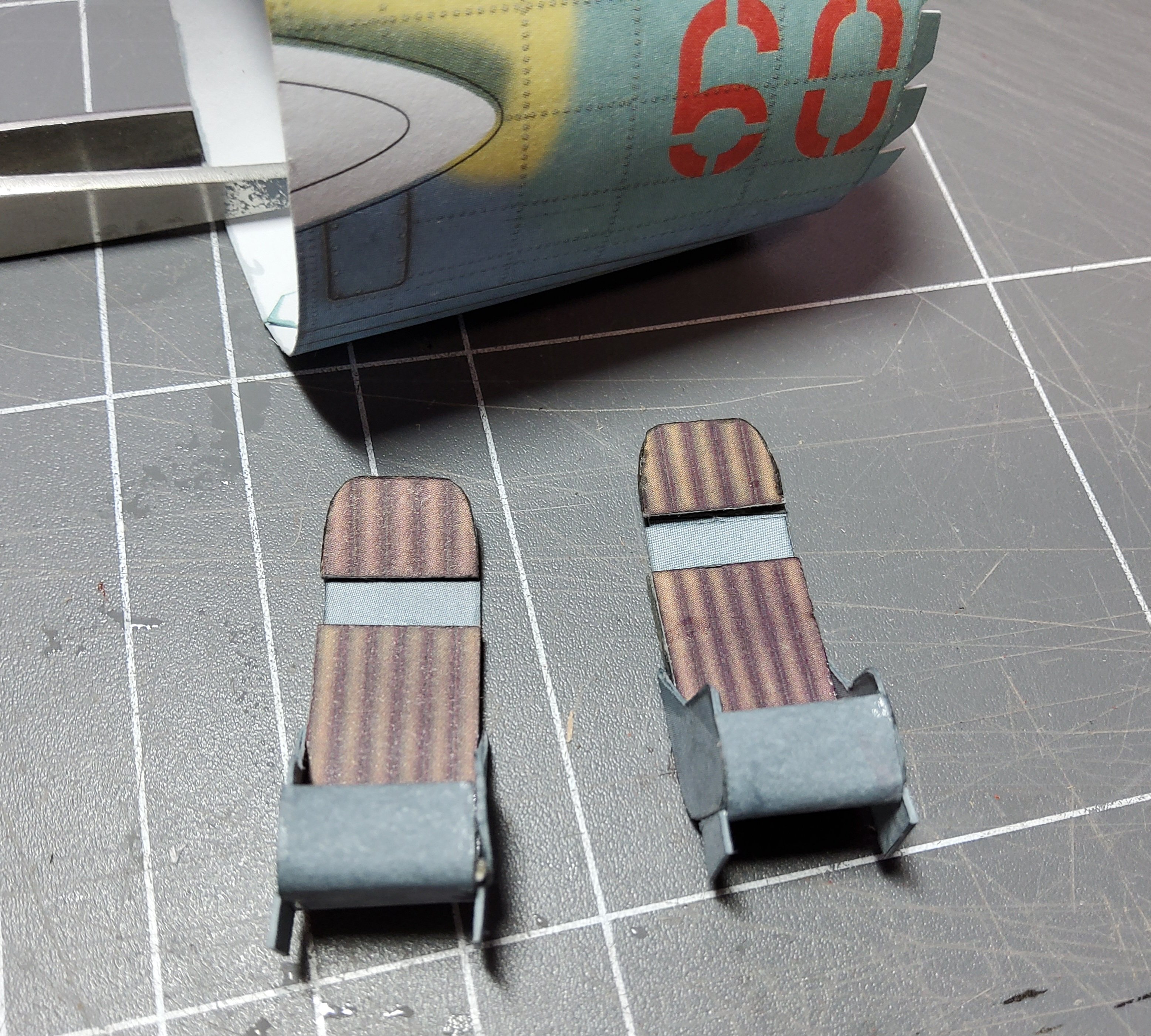
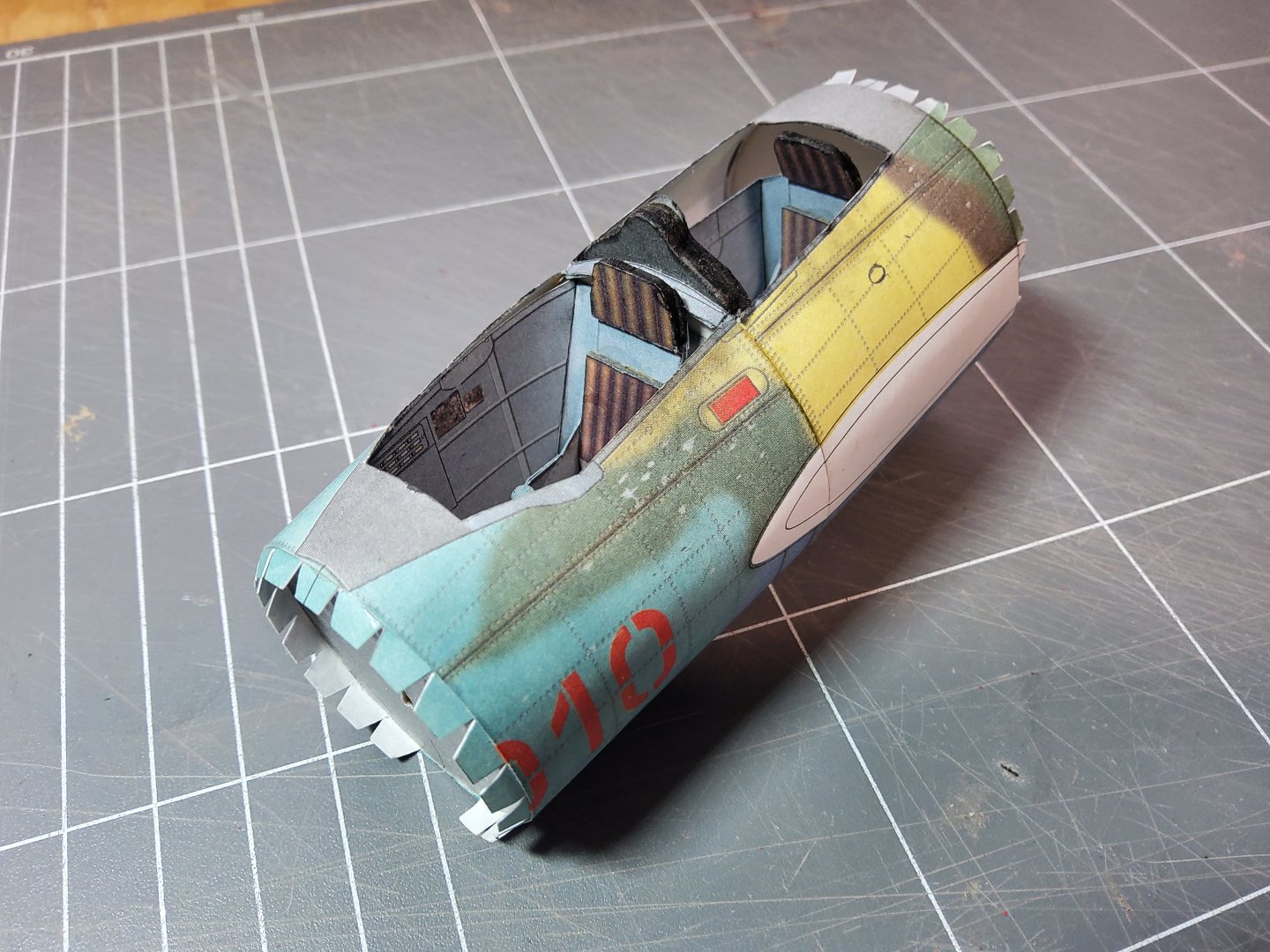
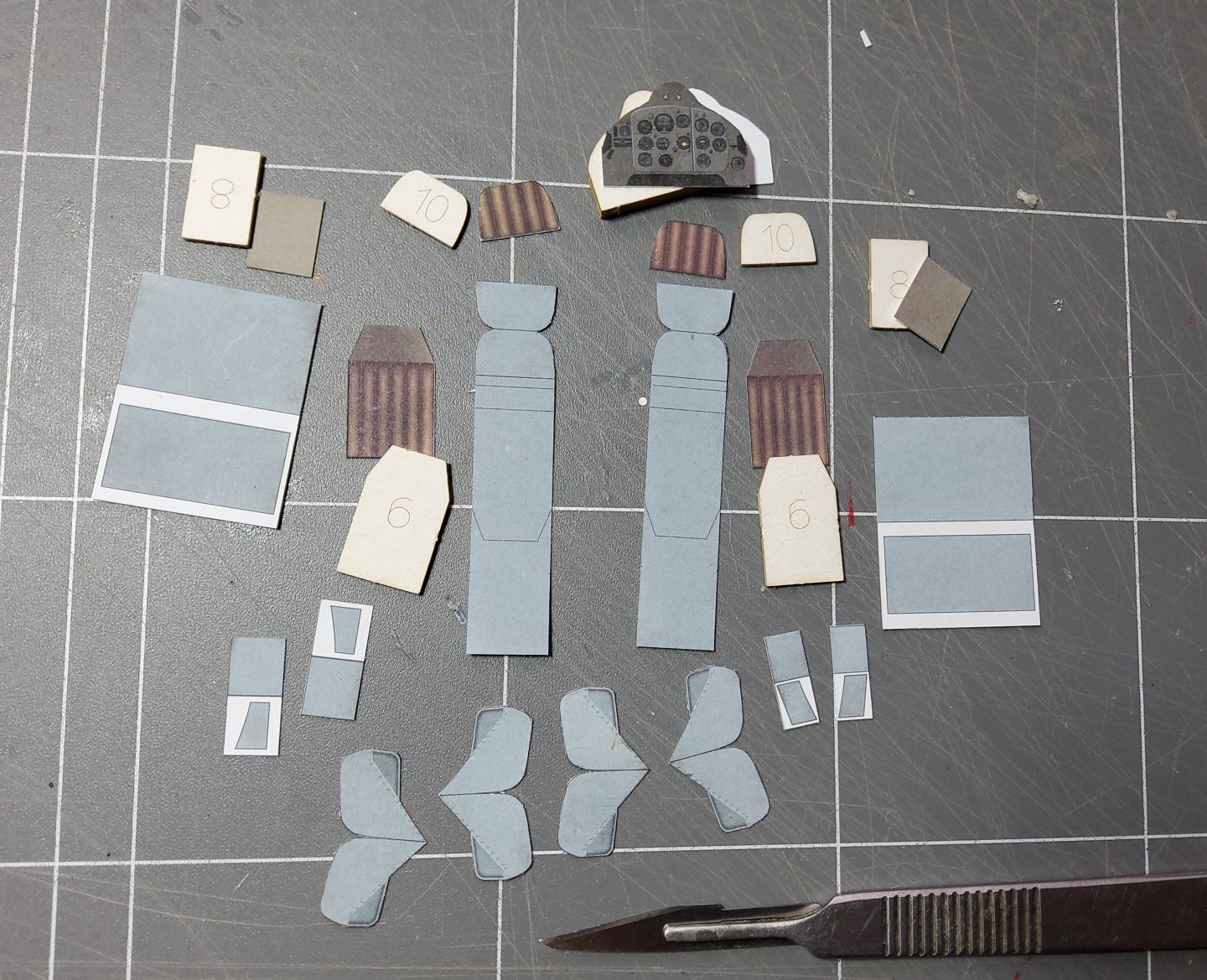
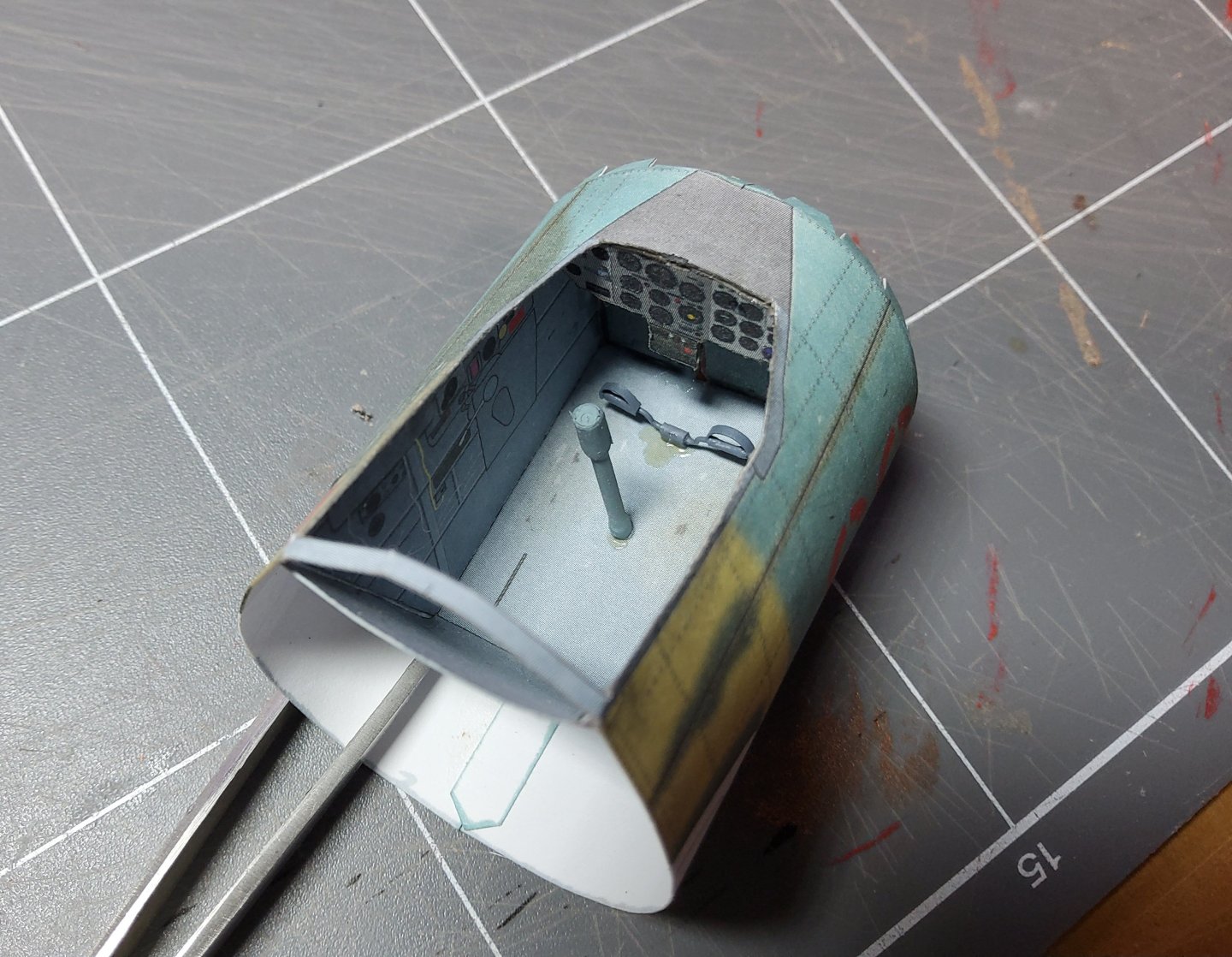
A little more work done. Parts for the seats cut out and ready for assembly. Some parts need laminating, others doubling. The assembled seats. The only real problem I had was that the laser-cut Part 8 ( the cushion for the seat) was too wide to fit in and had to be trimmed. The printed part was fine. You can see the two parts on the top left and top right of the above photo. The pilot's tub has had the rudder bar and joystick glued in place. I didn't attempt to roll the printed part for the joystick into a 2mm or so tube, but used a piece of styrene rod instead. Thin paper was wrapped around the top to improve the appearance a bit. The tub was then glued into the fuselage. Cheers

-
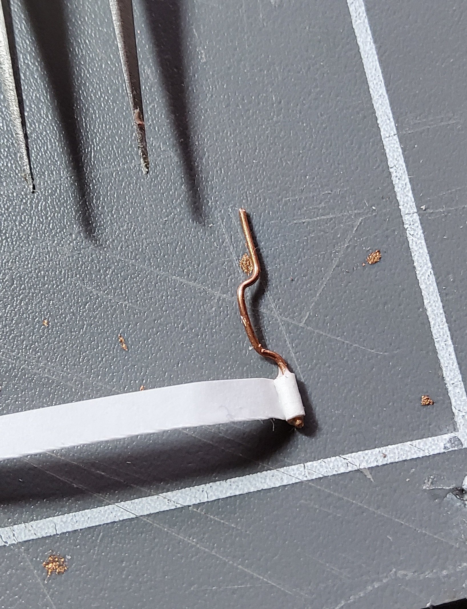
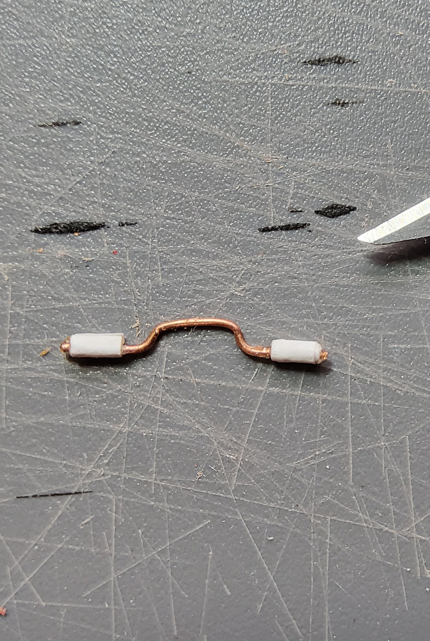
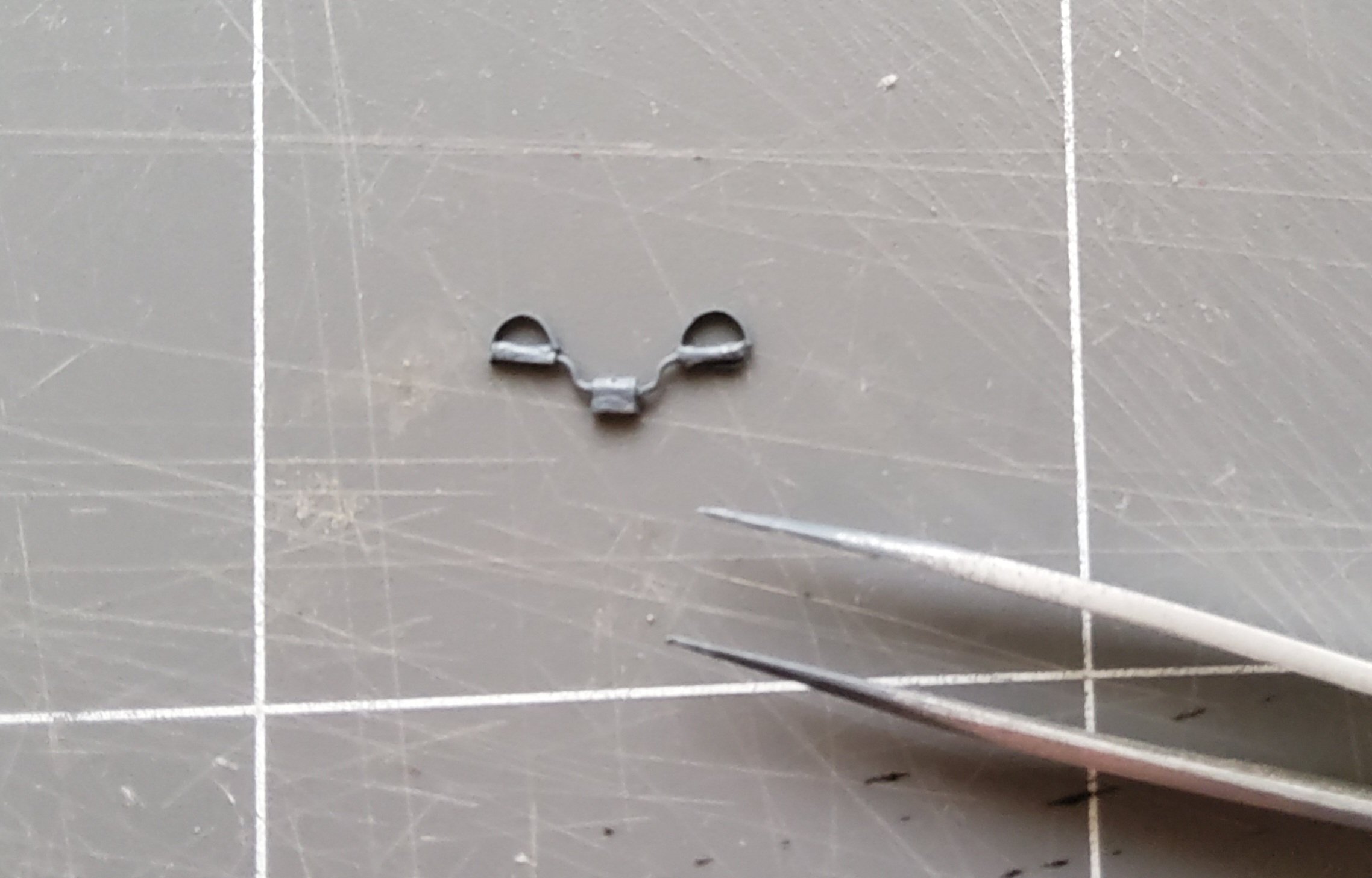
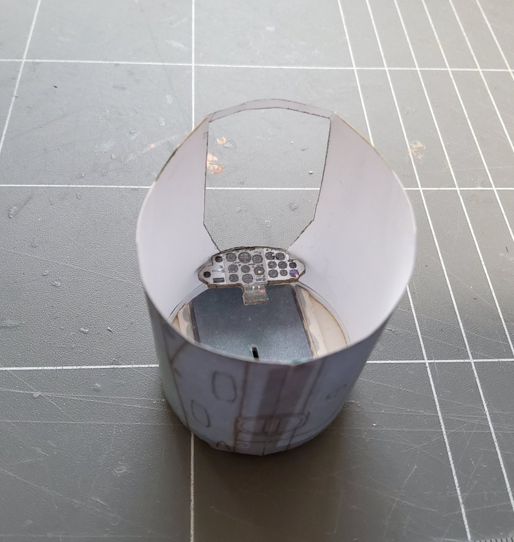
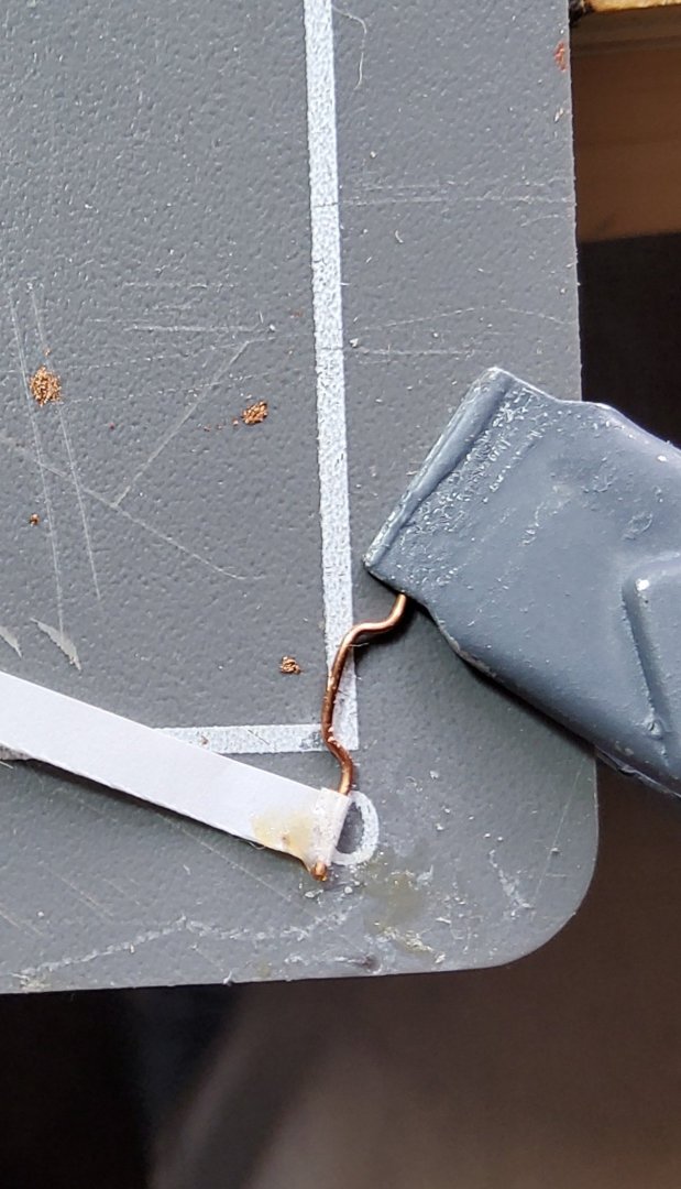
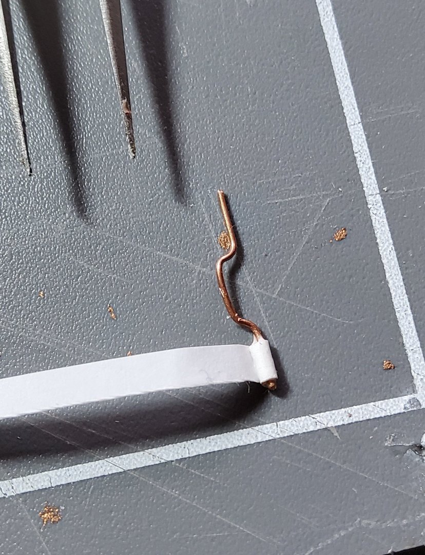
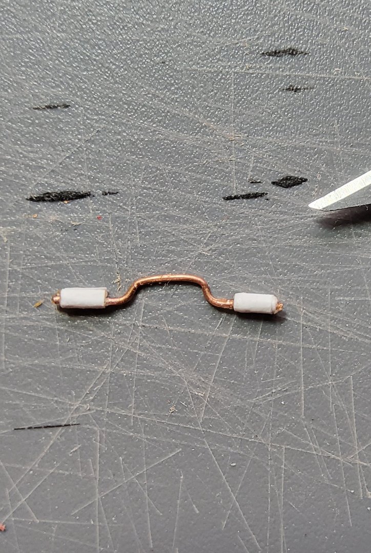
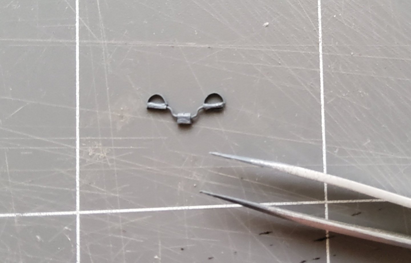
Next was laminating the instrument panel to the laser-cut piece, then glueing it in place. The bulkhead has been coloured to more-or-less match the cockpit interior colour, and some scrap laser-cut fret has also been added to give a better glueing surface for the cockpit tub when this is installed. I then decided to tackle the rudder bar, even though this will not be visible when the fuselage is completed. The bar is wire, formed following the printed template, with card "pedals", simplified loops actually. The wire was easy enough, but then it became more difficult. I decided to wrap thin paper around each side of the bar to make it look a little more realistic. It is not possible to wrap normal paper around a 0.5mm wire (the size I used), so instead I used the very thin paper that forms the receipt from a supermarket cash register. I had several goes at doing this, finally settling on two wraps. The glue used was something called "Roket Card Glue", which gave just enough adhesion between the paper and the wire to allow a full wrap to be done. The following photos are actually from a failed attempt, but the technique was subsequently used successfully. The first photo shows the strip of paper being glued to the wire, in the second three full wraps have been done and the third shows the finished bar before the pedals were done. The pedals were attempted using this particular bar, but this was a failure, so I started again. Finally a successful rudder bar 😁. Cheers
-
Chris, to go back a few steps. Just how did you do the rudder bar? I've had one go with a poor result, and will try again tomorrow, but any hints would be appreciated. The wire is no problem but I have no idea how you managed to get the foot loops so even and glued to the wire. Thanks. Cheers
-
Good idea, I've done the same.
-
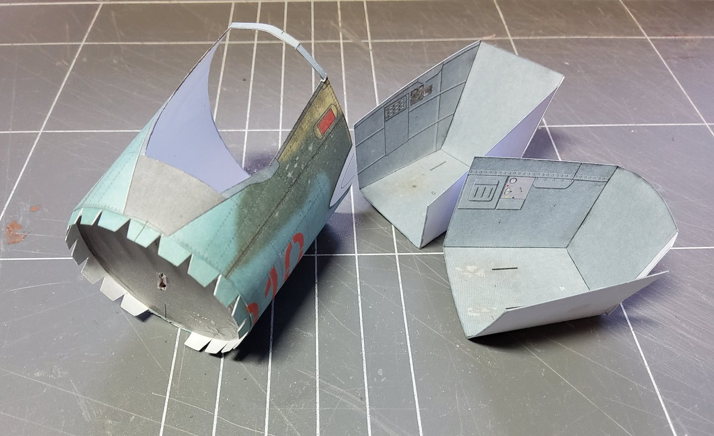
Thanks Chris. Had a chance to do a little on the SBLim-2A while waiting for glue to dry on Harpy. I got the first fuselage section joined after rolling it in my fingers to give it some shape. The joiner strip that goes on the forward edge of this was next, after trimming it to allow for the nose wheel. Then the lasercut former at the front of this section was readied by first laminating it with a print, then scraps of lasercut fret were glued on the cockpit side to give the pilot's seat a better gluing surface, and the area in between these strips was coloured to closely match the cockpit colour. Getting this to seat correctly in the fuselage section was a test of my patience, but finally it was done, though the canopy support at the rear of the fuselage section took a bit of collateral damage. 🫢. Anyway, all should be good. The two cockpit sections were cutout, folded and partly glued, following Chris' advice, to make it easier to install the interior parts of the cockpits. Cheers
-
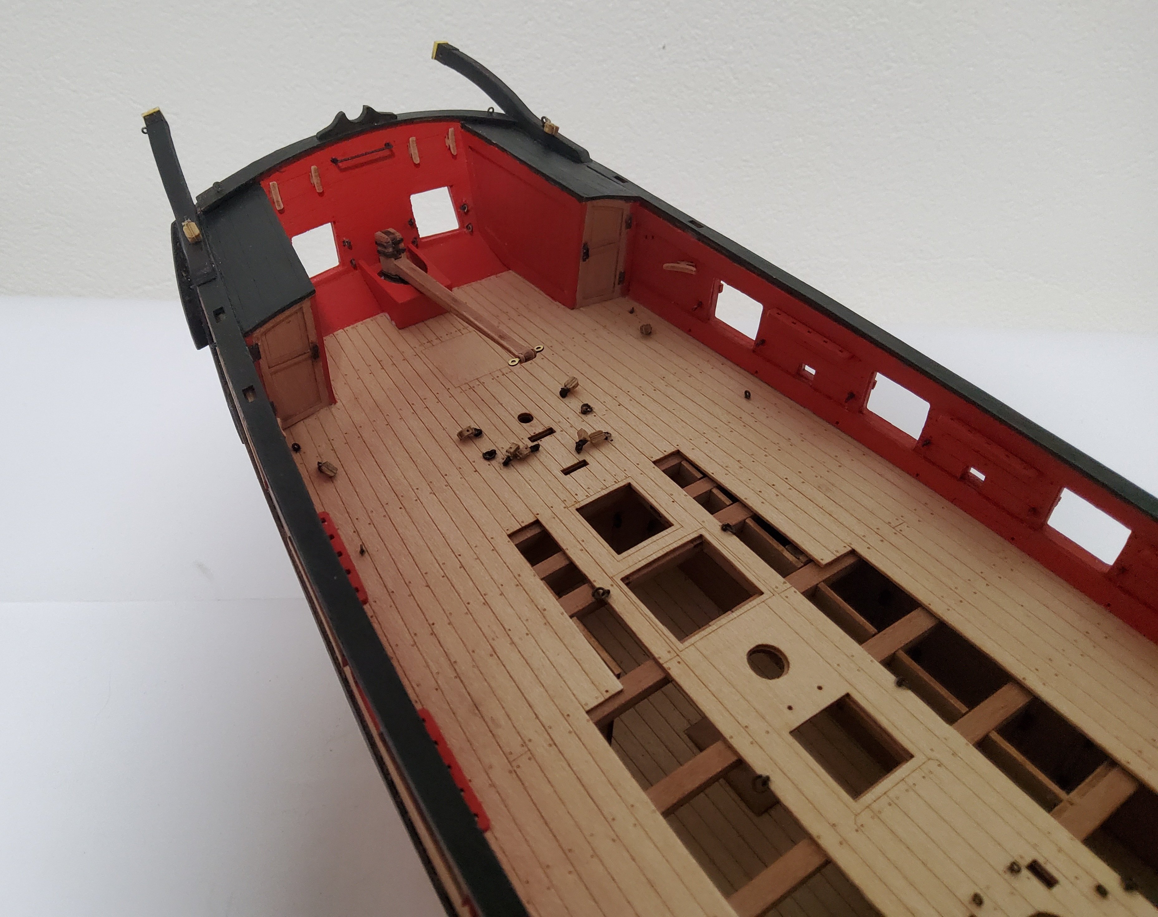
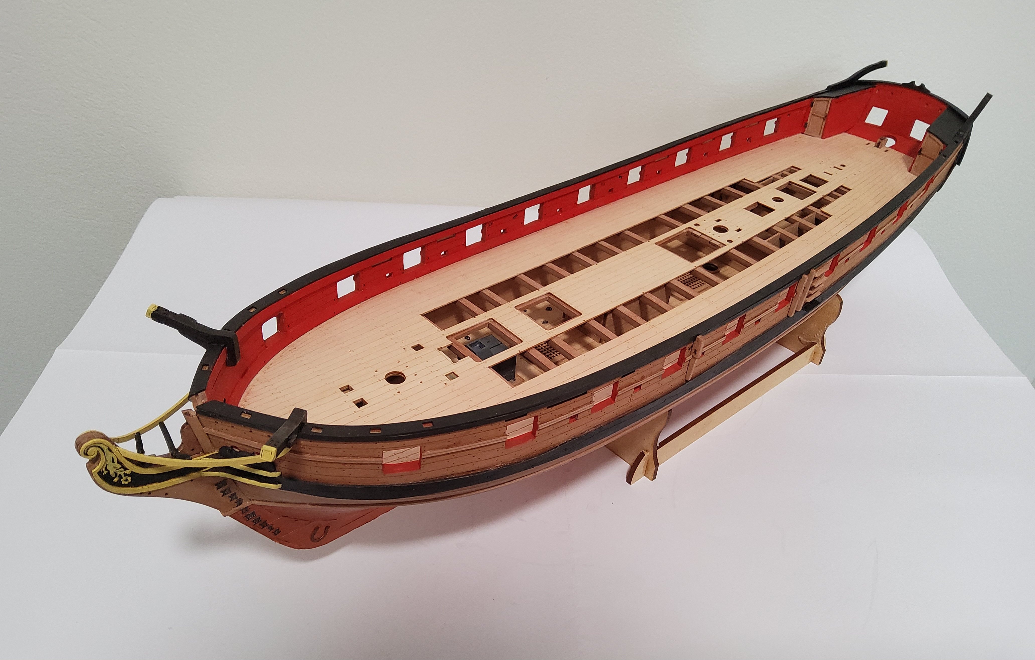
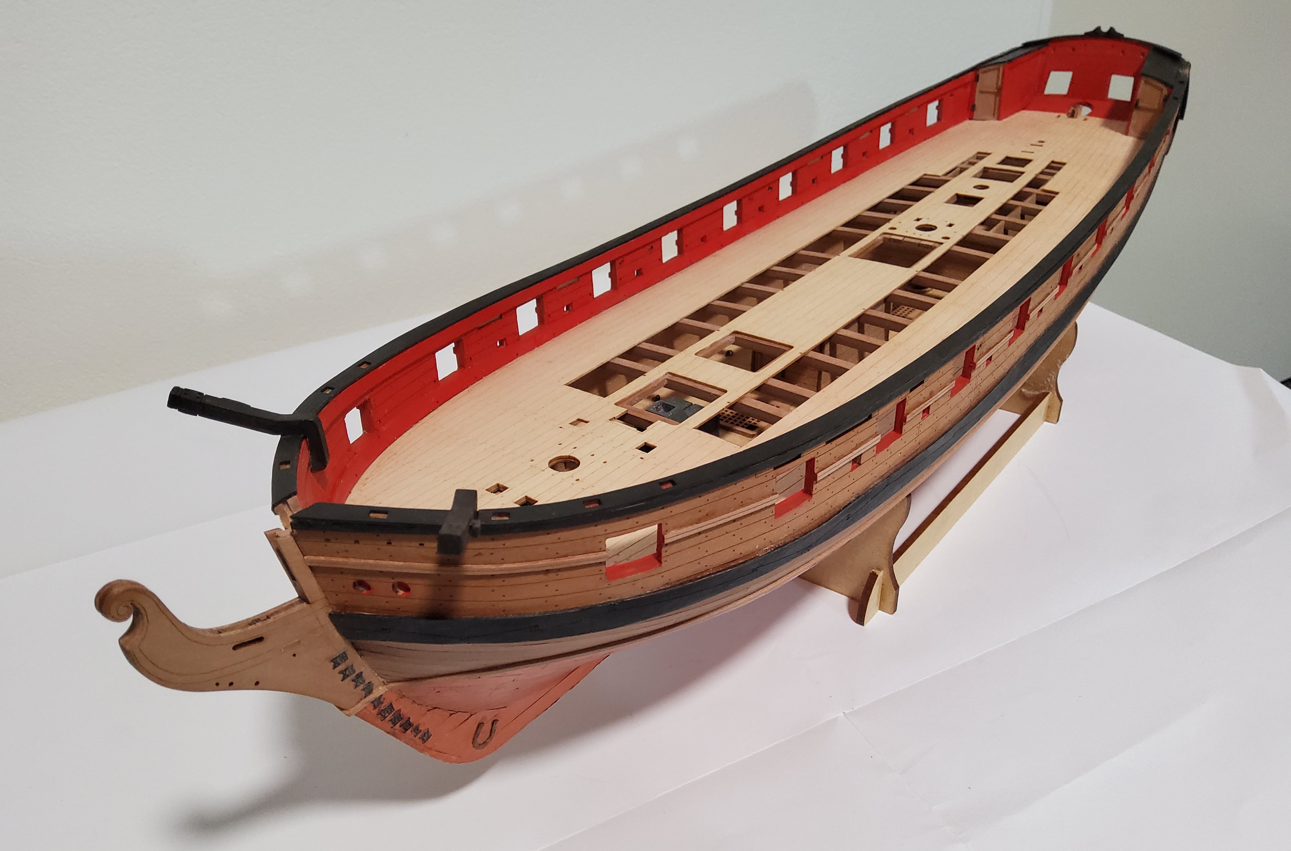
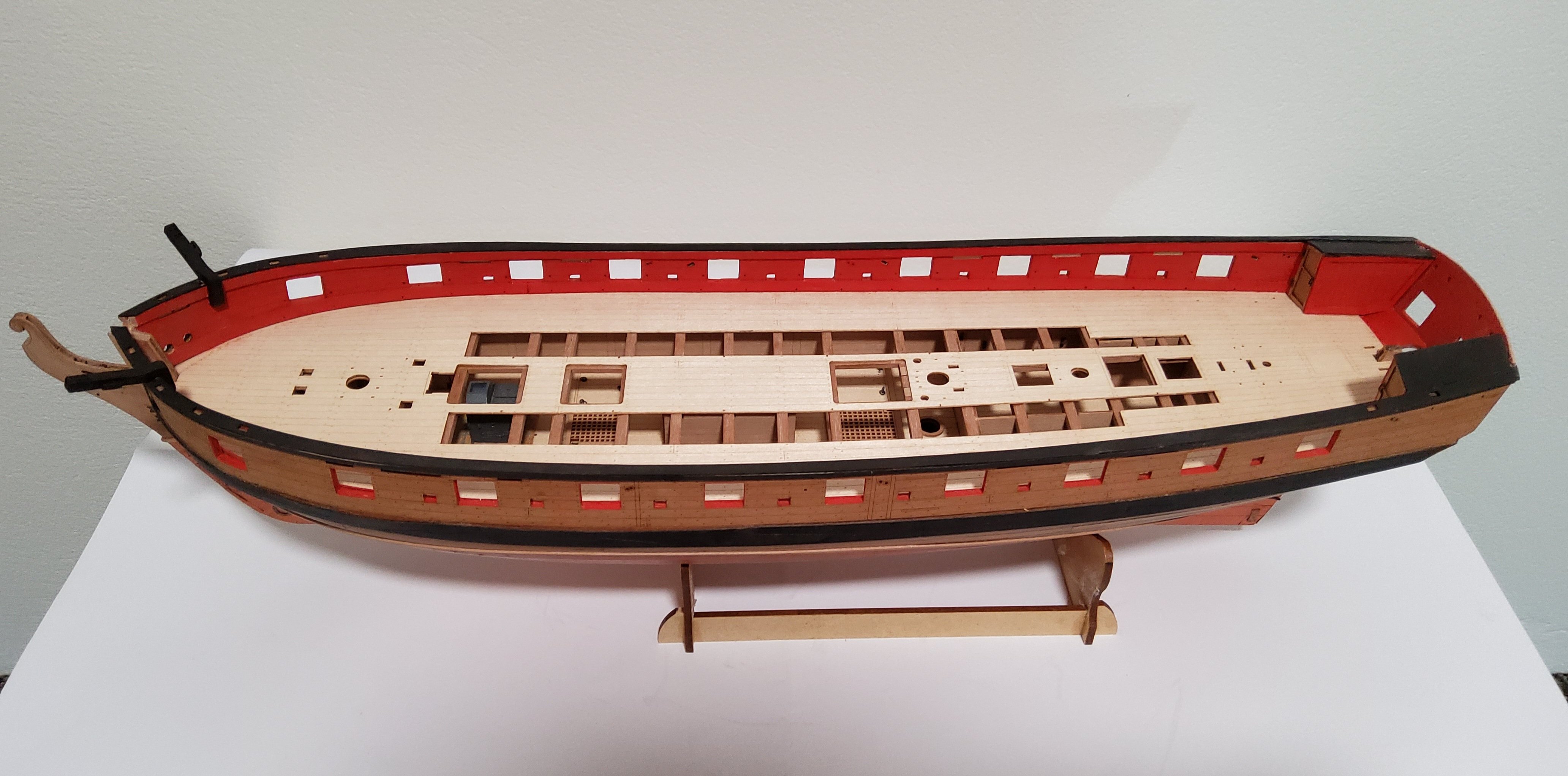
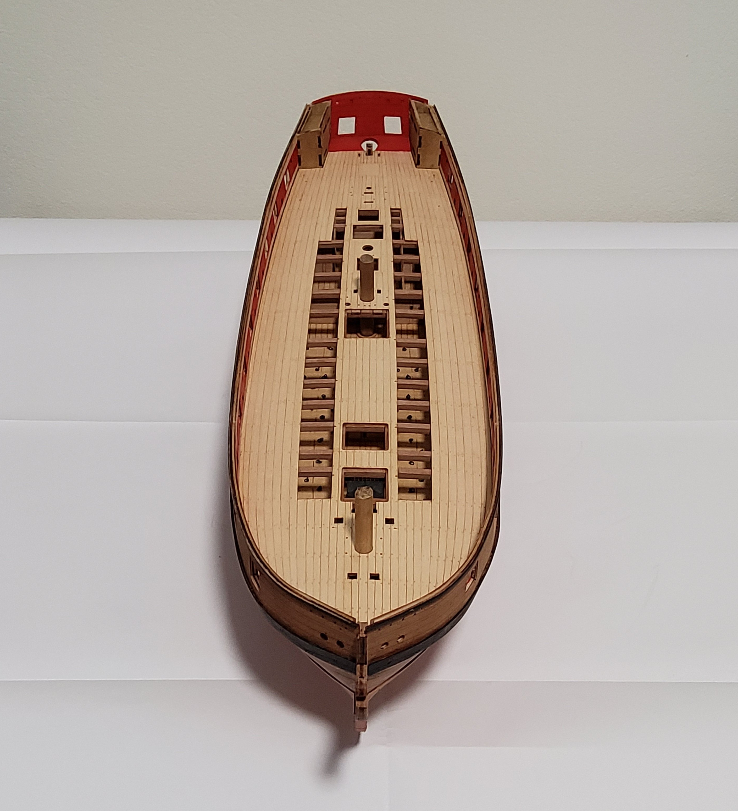
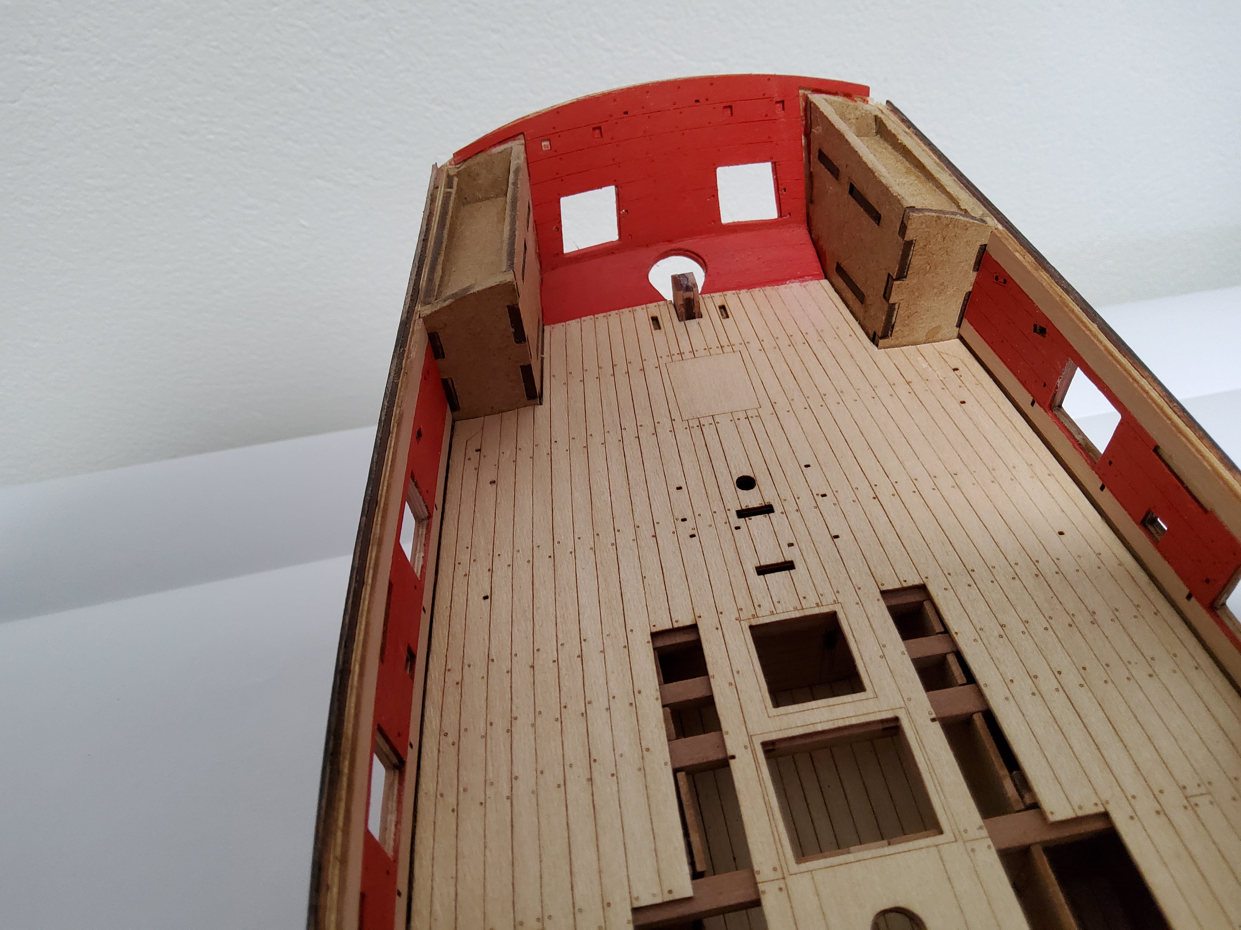
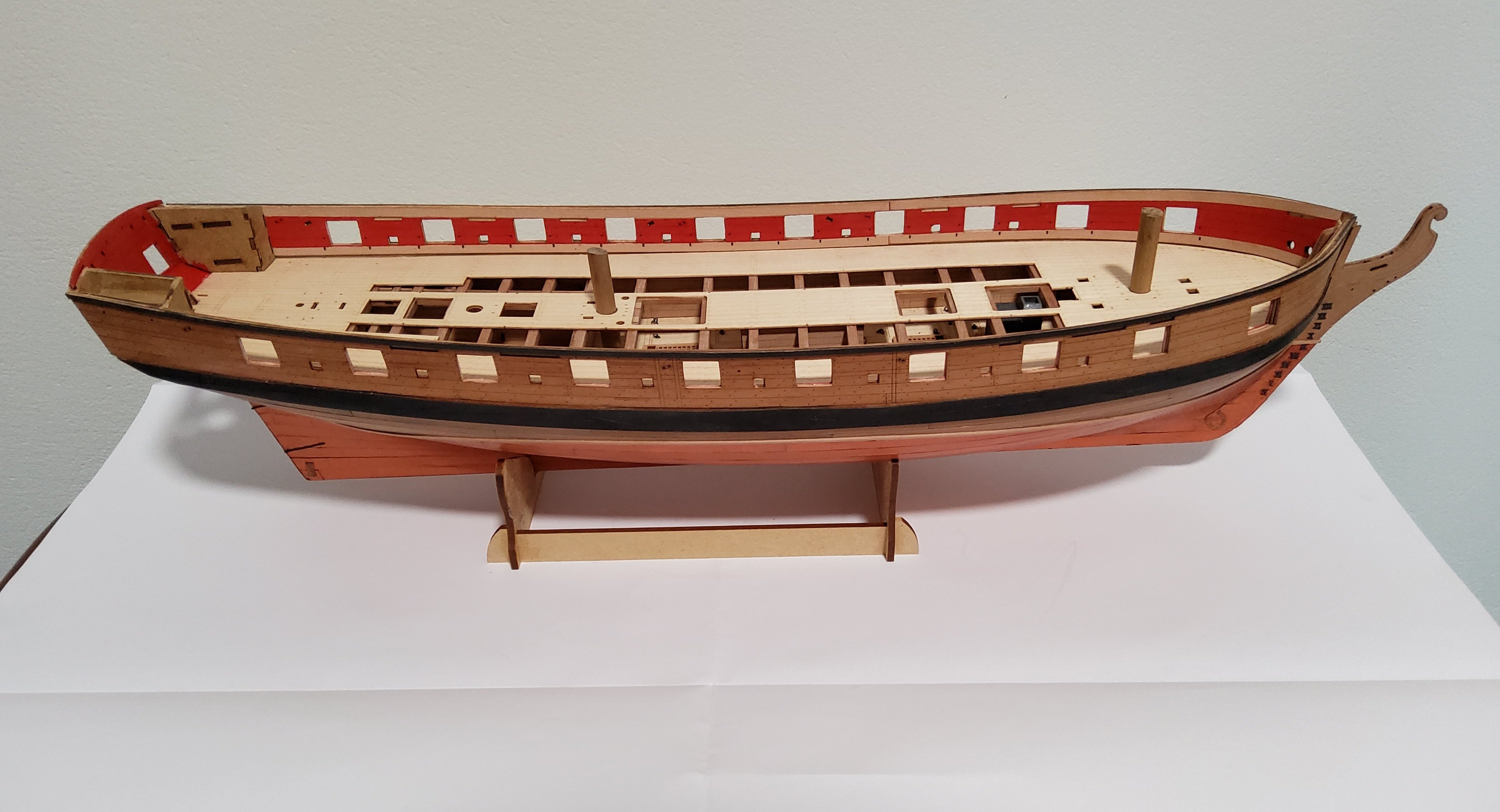
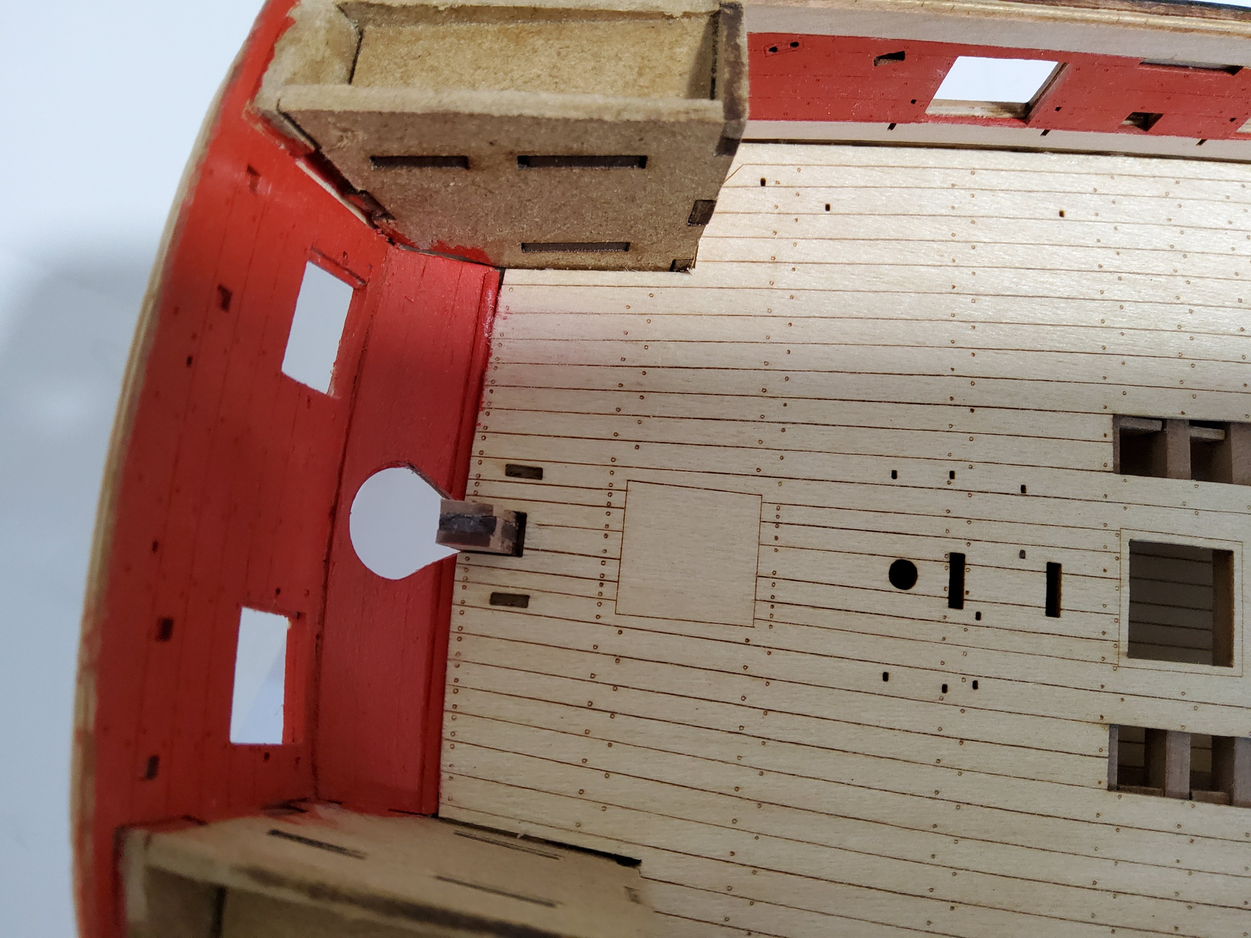
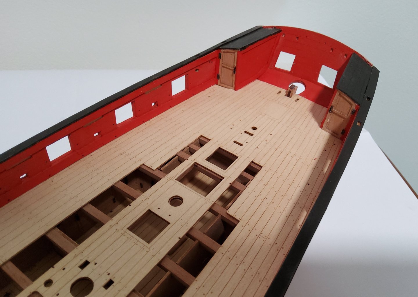
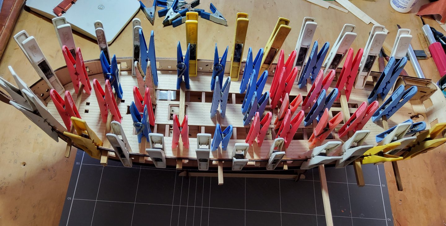
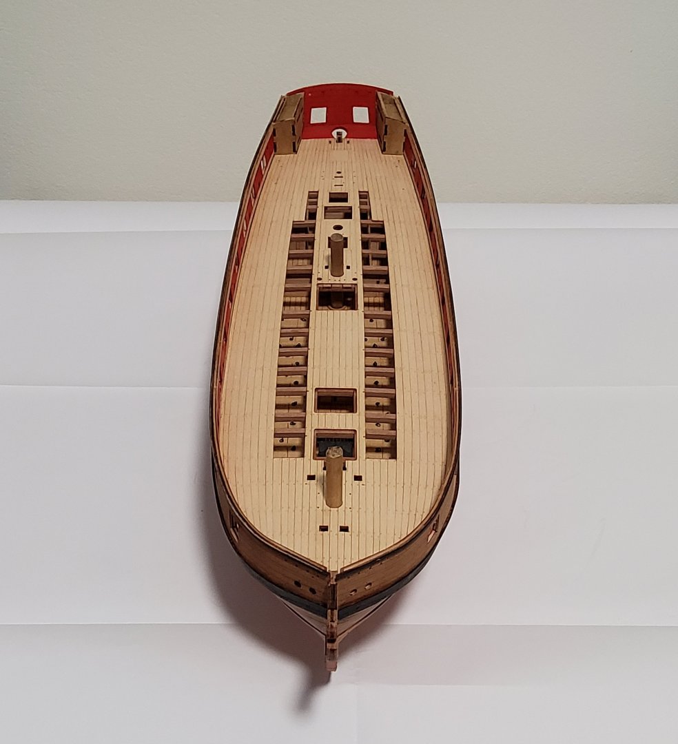
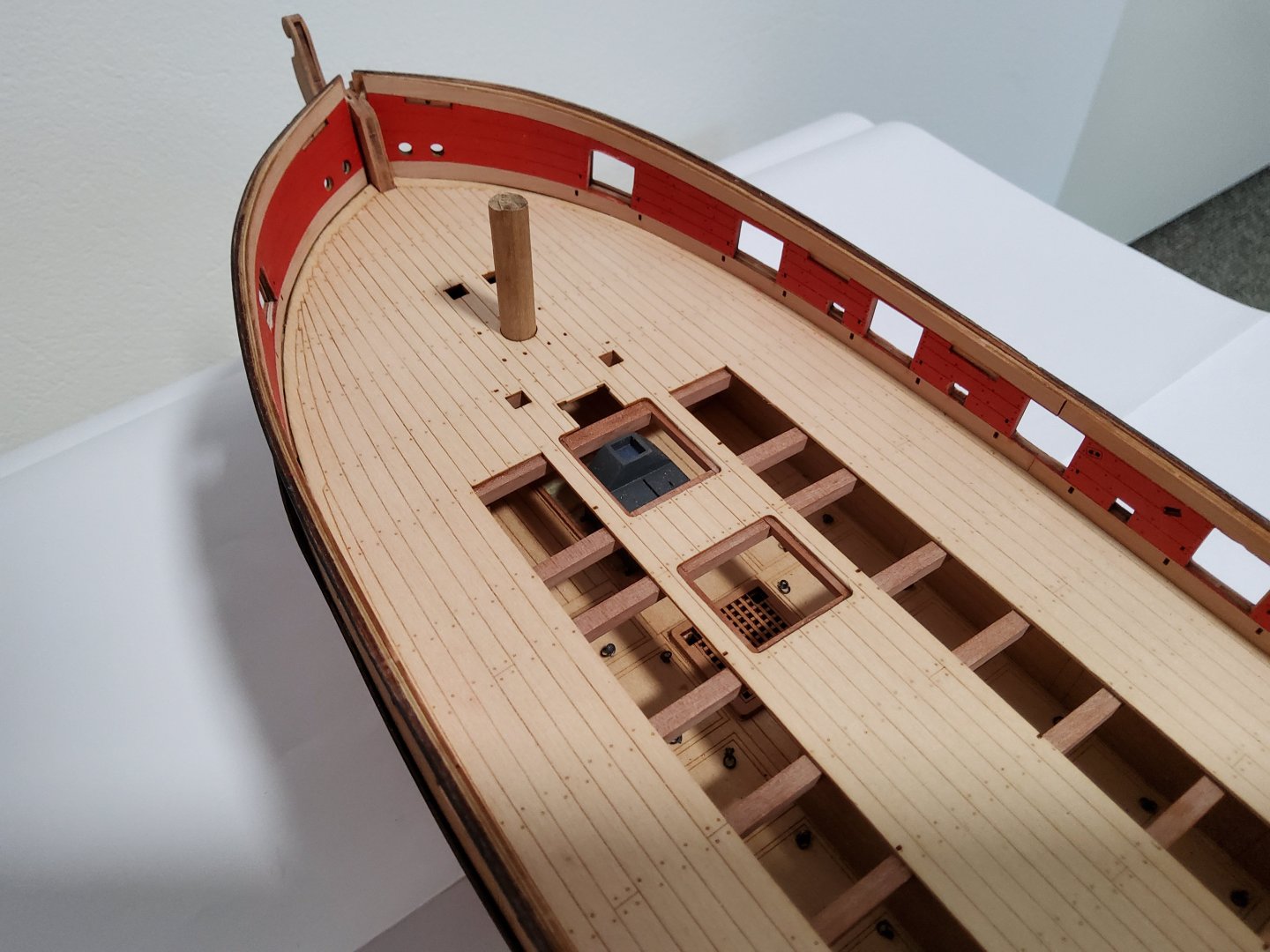
Thanks to all those who haved "liked" this log, and also to those who have just dropped by. The next job was to install the deck. Firstly, the bulkhead extensions had to be removed and the stubs sanded flat with the sub-deck. The actual deck was then carefully dry-fitted, with only slight sanding required to get it to sit correctly. Two short lengths of dowel placed in the masts' locations and extending through the lower deck, were used to ensure the deck lined up correctly. The deck has two sections to be removed, if wanted, so that the beams and lower deck would be visible. The instructions say to make a pencil mark on the beams where the limits of the deck are, so that glue would not be applied onto the parts of the beams where these are to be exposed. While I had the deck dry-fitted, I replaced the two cutout sections with short pieces of double-sided tape on their bottoms so that they remained in place as I lifted the deck in preparation for gluing. I now knew exactly where I should apply the glue. Glue was applied and the deck replaced. There was a minor problem though, keeping the deck in contact with the sub-deck while the glue was drying (i was using PVA) - I do not have any suitable modelling clamps nor suitable weights to do this, so the laundry was raided. The inner bulwarks and the two stern counters were affixed after the deck had dried. The bulwarks were painted first, then glued in place. I didn't find it necessary to soak the forward sections of the bulwarks, and only a slight sanding, mainly the forward edge, was required. The rear sections also needed just a slight sanding. The counters went into place easily enough, but there was a distinct gap between the bottom edge of the lower counter and the deck, as it is designed to tuck under the edge of the deck. I glued two narrow strips of 0.8mm pear in place to reduce the visible effect of this gap. The two narrow strips of pear between the counter and the deck. The next job will be the two cabins at the stern. Cheers


-
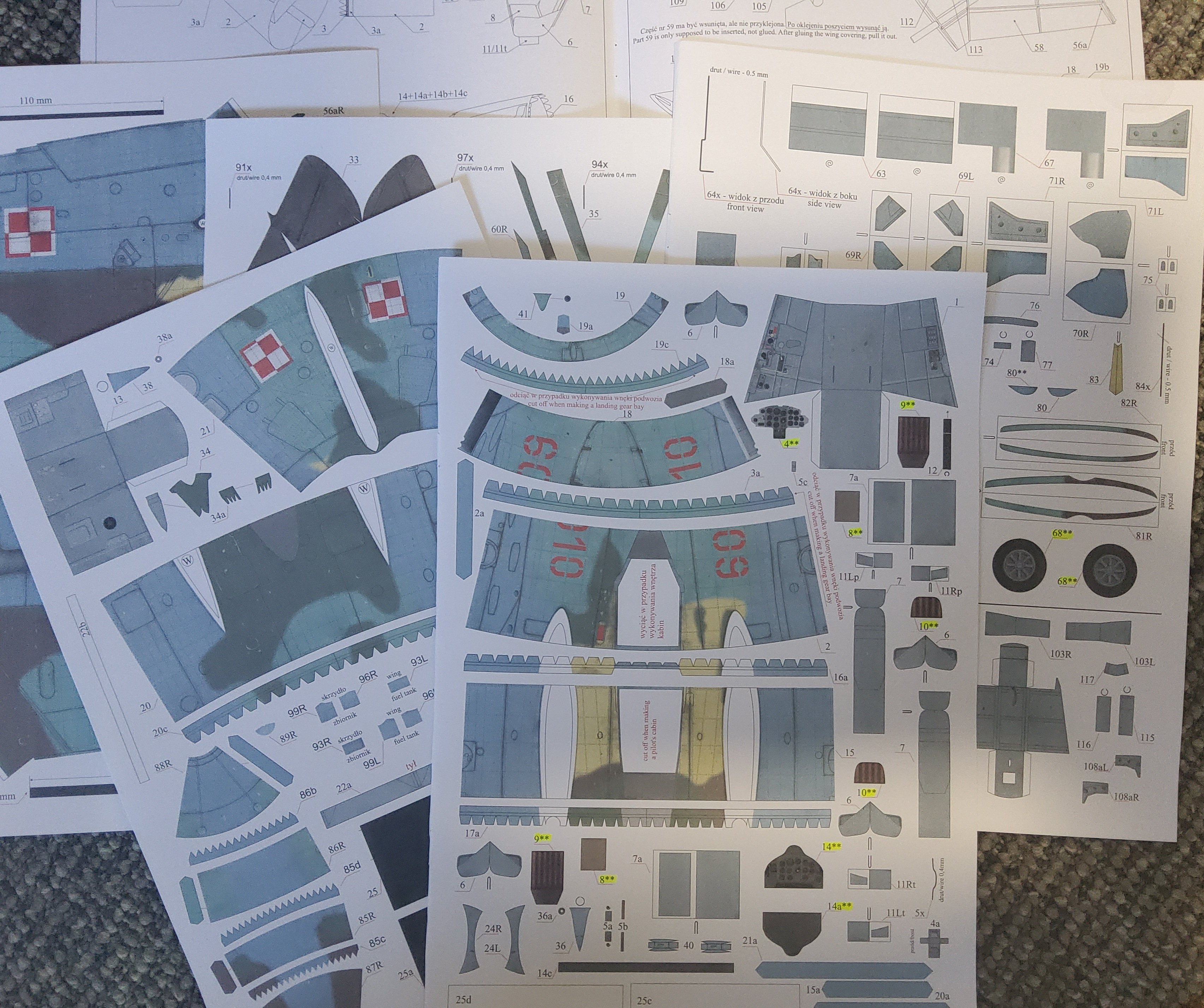
My kit finally arrived (including laser-cut parts and a clear canopy), and I had a chance today to have a good look at it. Chris has given a description of the kit so I'm not going to repeat that. There are plenty of English instructions which need to be read rather carefully, referring to the six sheets (five colour, one B&W) of parts plus the two laser-cut sheets and the construction diagrams, as required. Many of the card parts need laminating onto the laser-cut sheets and in the photo below, the topmost sheet shows some part numbers highlighted, these are those that need laminating. Many of the parts have a thin black border but no indication as to whether the cut to release the part should be inside the line, along the line or outside it - I'm going with cutting along the line. Not much done yet, the build will be slow as I'm building Harpy as well. The first photo simply shows the five coloured sheets of parts (sorry about the colour balance). The second shows some of the parts for the two cockpits and the first of the fuselage sections. One thing to notice is that an opening has to be cut in the fuselage section if the pilot's cockpit is to be shown, and the front and rear cuts for this to be done are actually slightly curved, not straight. Cheers


-
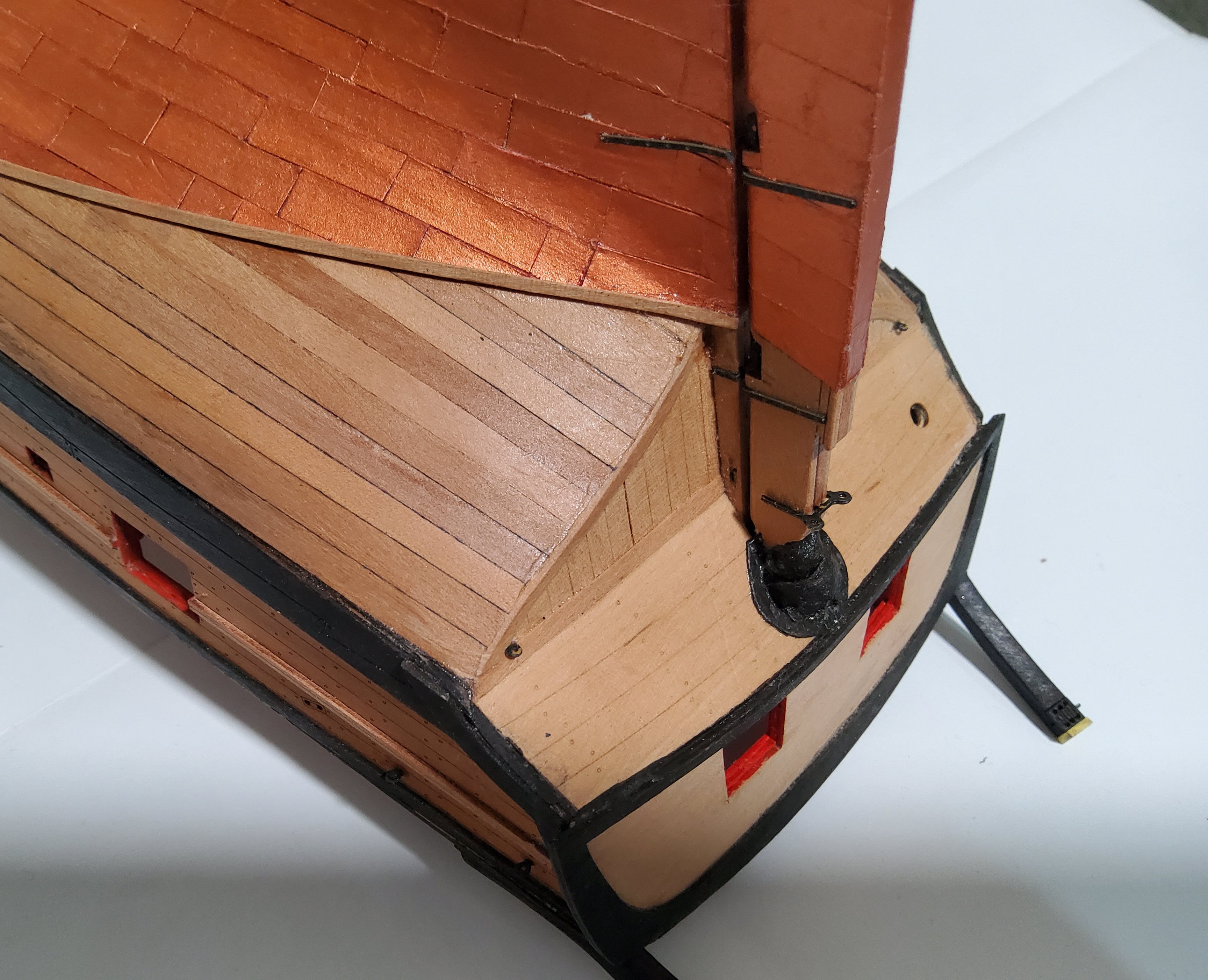
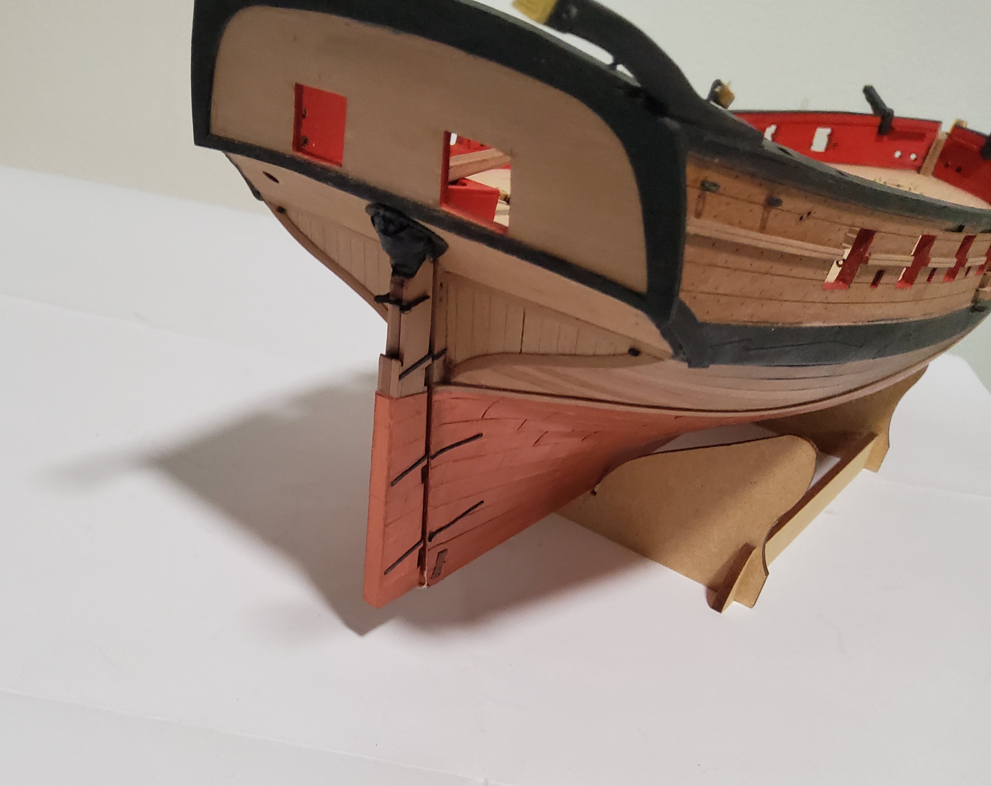
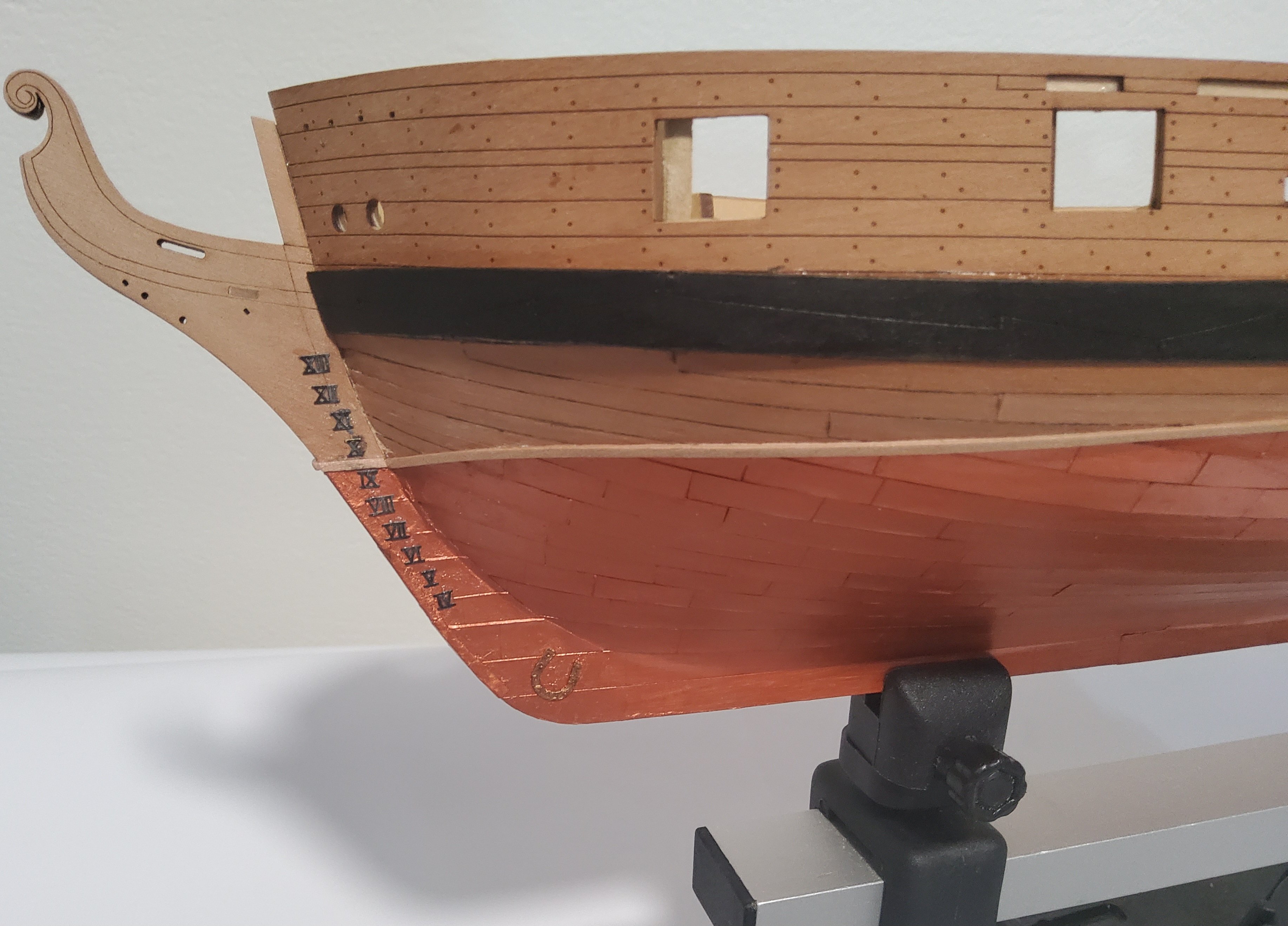
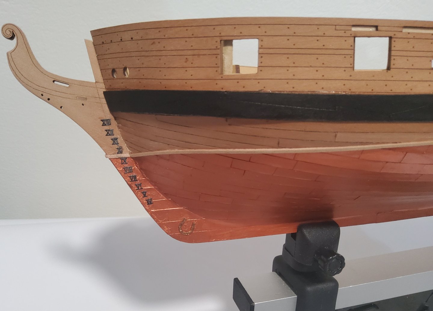
Just back from a holiday, so only a short update. The rudder has been finished, the batten above the coppering added, as have the depth markers and the horseshoes and fishplates. The batten is a 1mm strip cut from 0.8mm pear fret (pear is hard on knife blades 🤨). The depth markers were painted black and glued using gel CA - spacing was eyeballed. The horseshoes and fishplates were painted with a different, darker, copper paint than the plating simply to make them stand out slightly. Gel CA was used to glue them in place. The rudder is in place for the photos but not fixed. Cheers
-
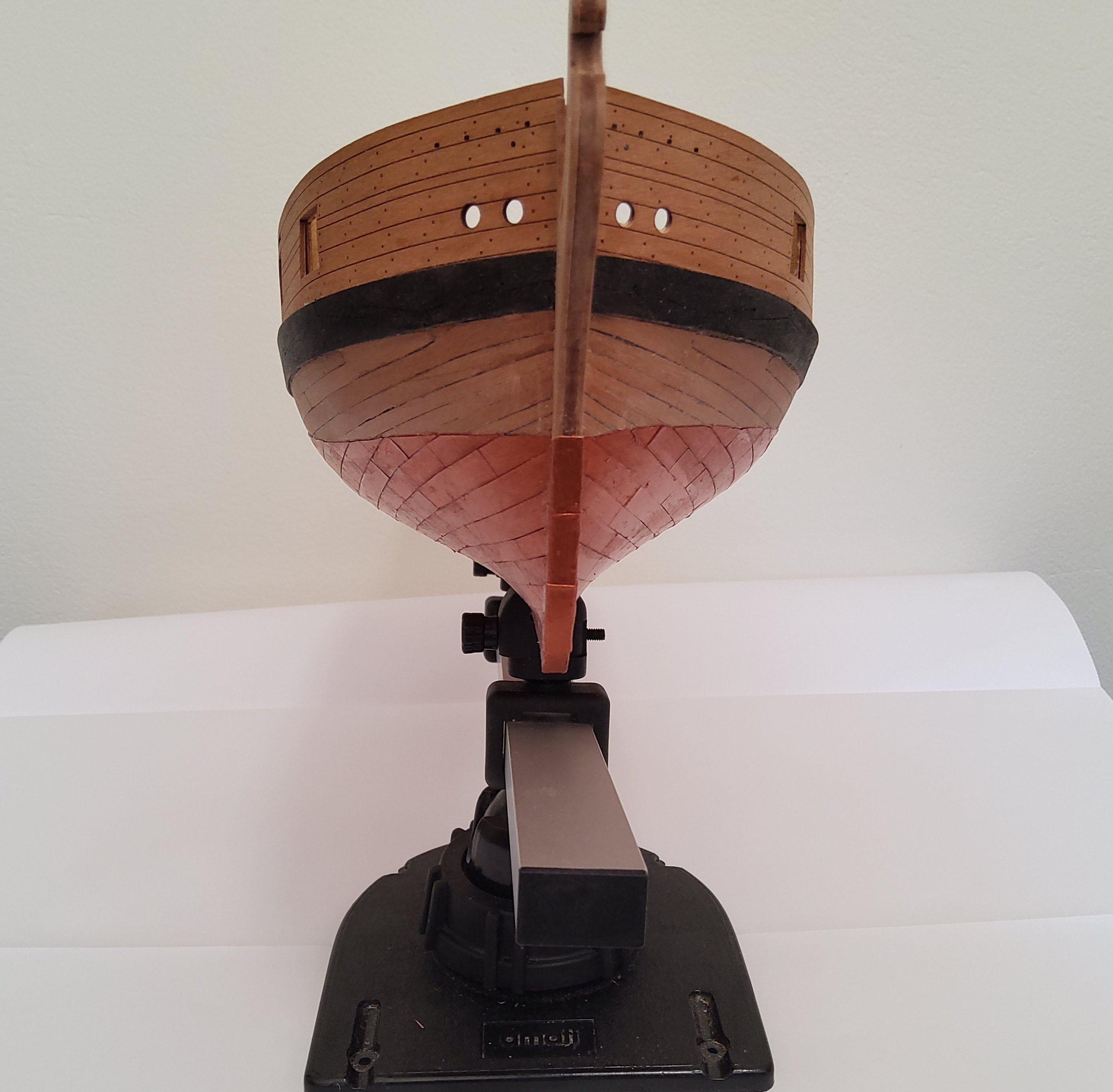
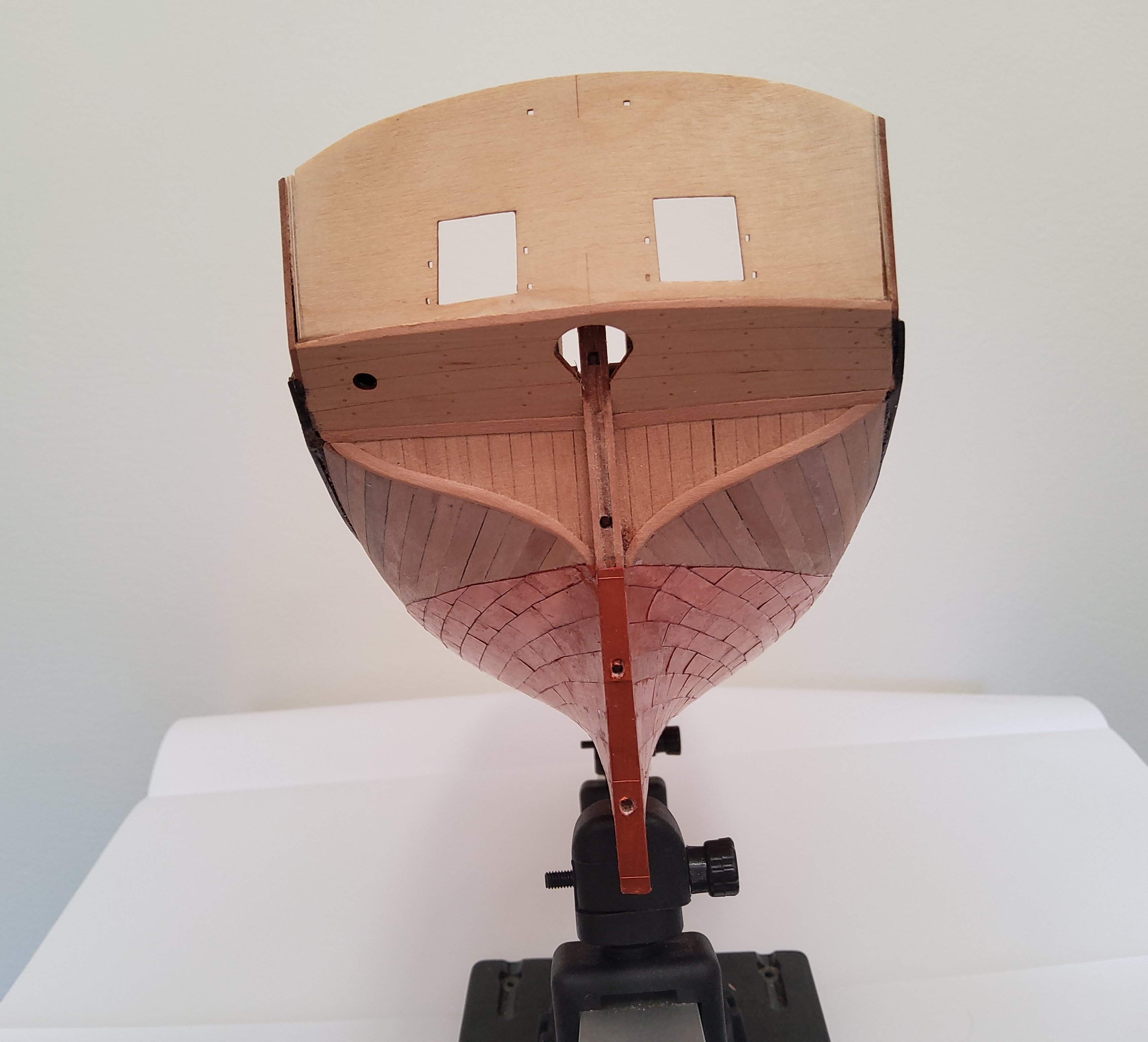
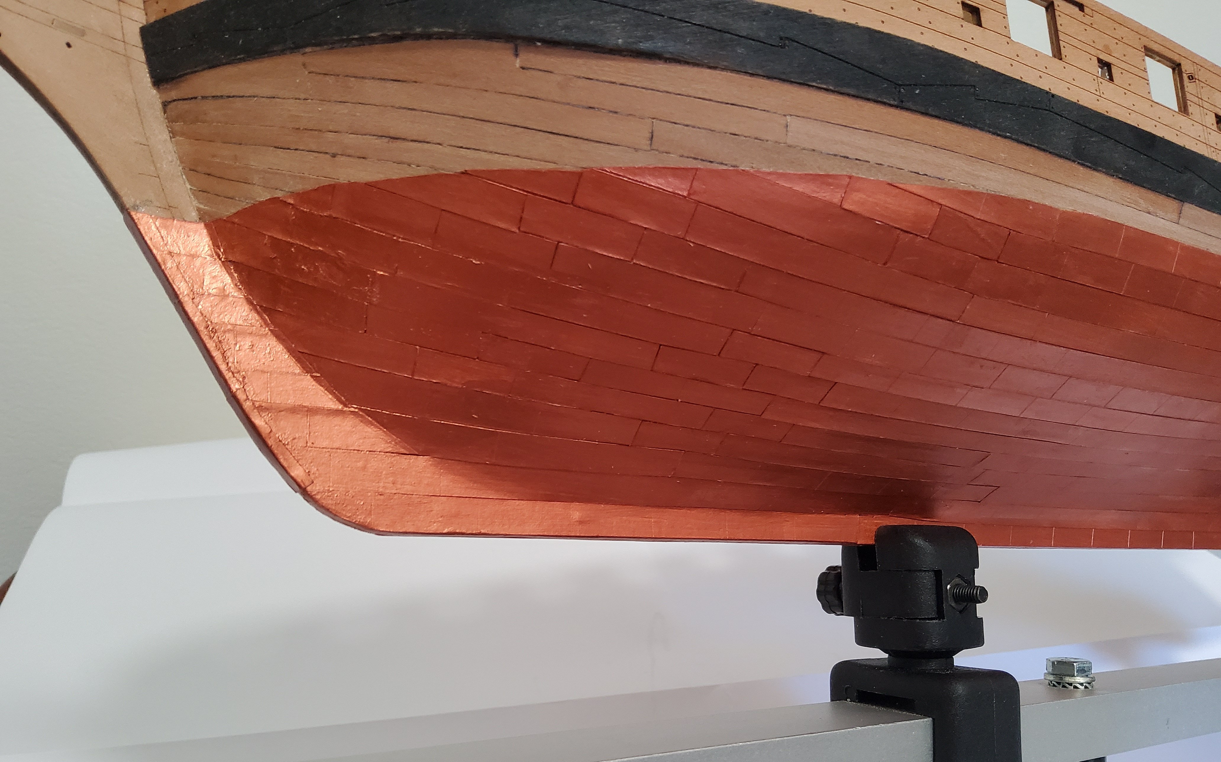
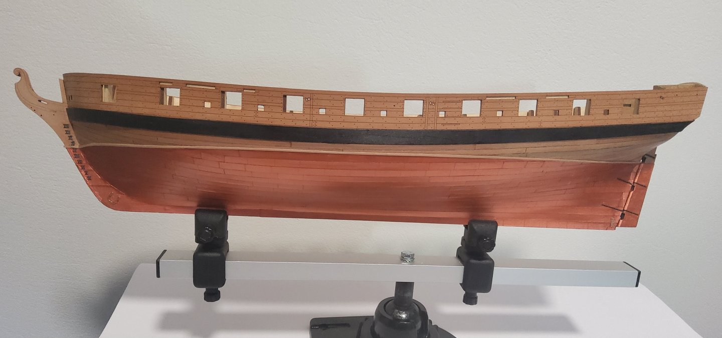
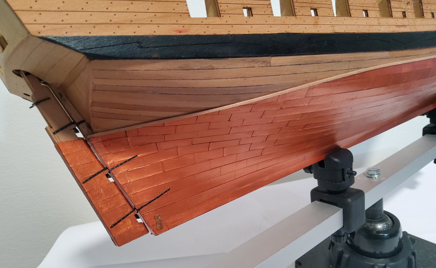
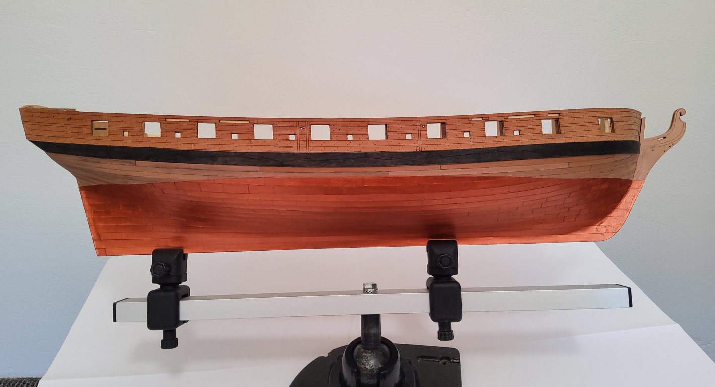
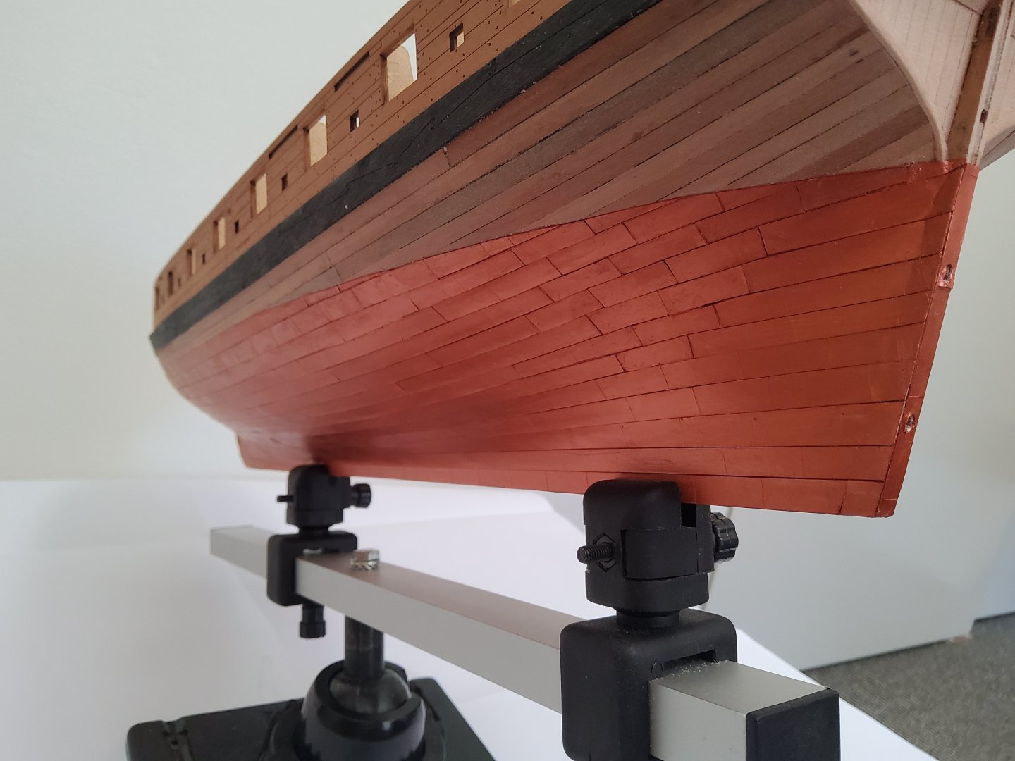
First, thank you to all who have stopped by, reacted or made comments. It is all much appreciated. The coppering is complete. A slow job, but I think worth it in the end. Gluing the card strips to the hull was done with common PVA, grab time was short leaving little chance of repositioning. Also too much glue, it being water-based, would result in the card becoming soggy and impossible to move. A few individual plates had to be cutout and replaced. Some minor touch up with paint was required. A narrow batten will be glued immediately above the copper plates. Cheers


-
Yeh, me too. Been there, done that, put the model aside for a while, then returned ro it later. My first wooden ship model was the AL Endeavour. Back before the Internet, so no help at all. Second planking was turning into a total disaster, so I let it be for a while, then took a deep breath and ripped it all off. Started again.
- 241 replies
-
- 2
-

-
-
- Vanguarrd Models
- Harpy
- (and 1 more)