HOLIDAY DONATION DRIVE - SUPPORT MSW - DO YOUR PART TO KEEP THIS GREAT FORUM GOING!
×


Richard44
-
Posts
429 -
Joined
-
Last visited
Content Type
Profiles
Forums
Gallery
Events
Everything posted by Richard44
-
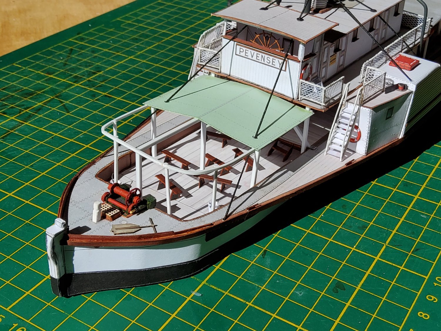
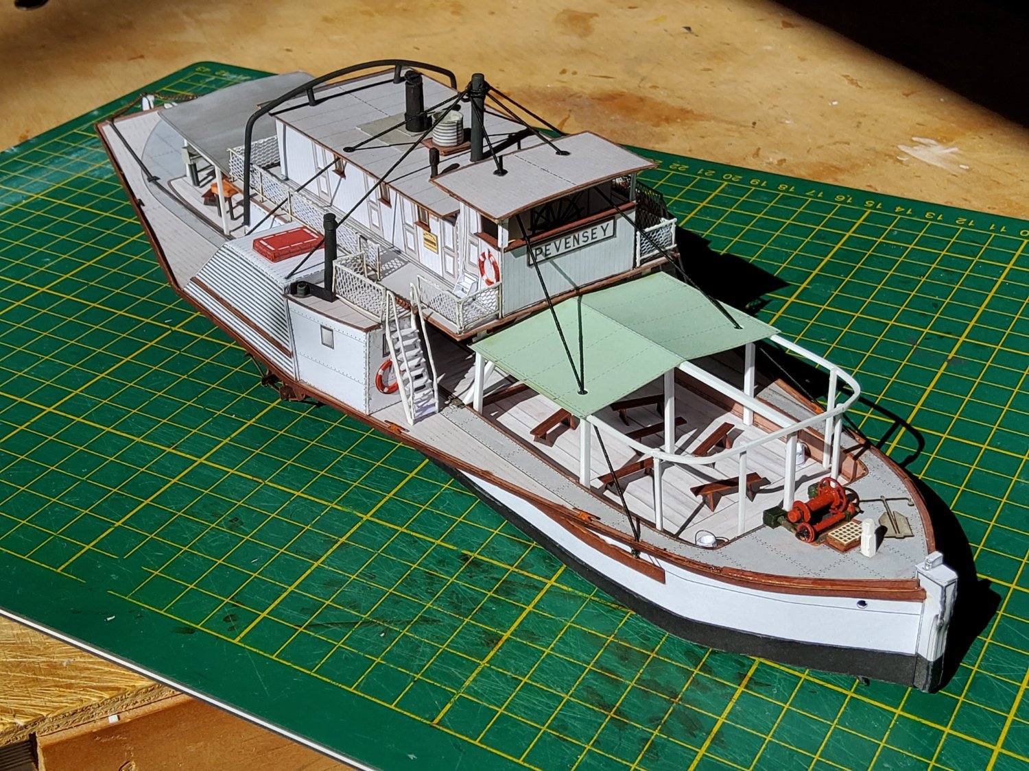
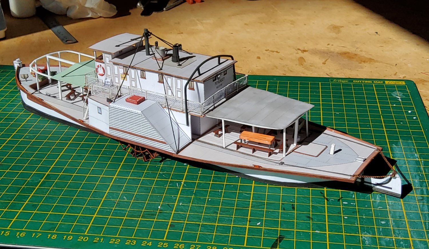
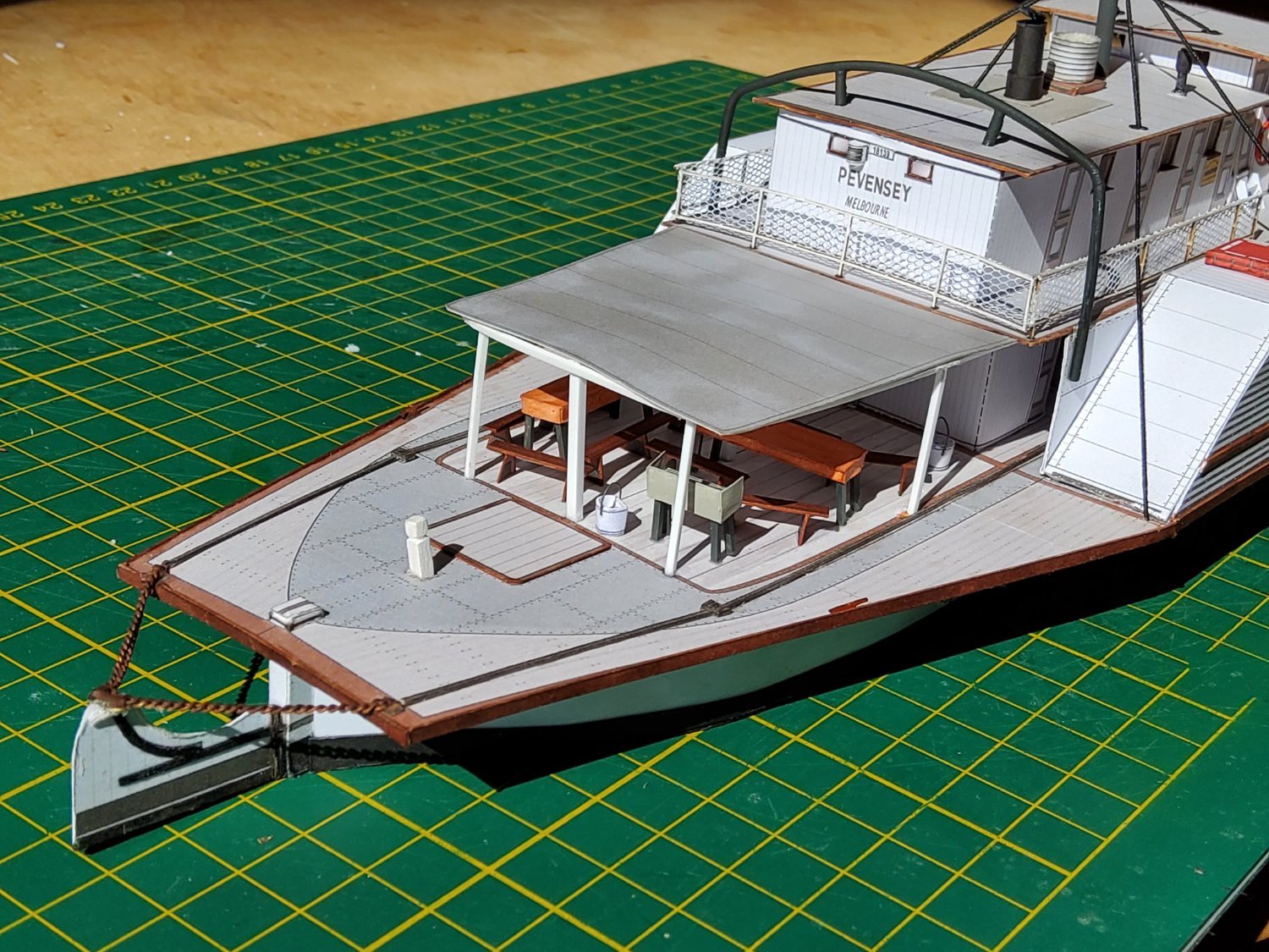
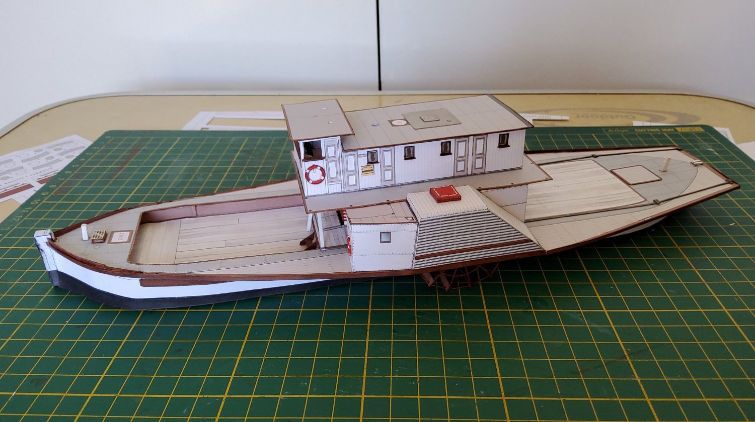
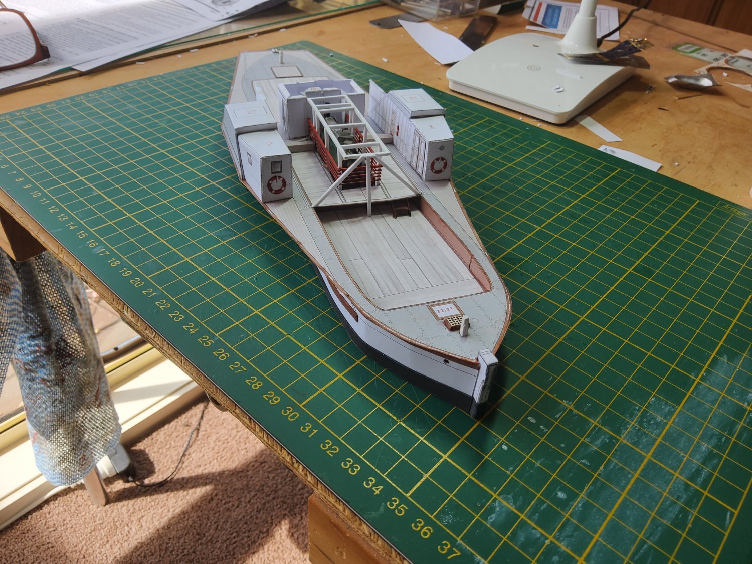
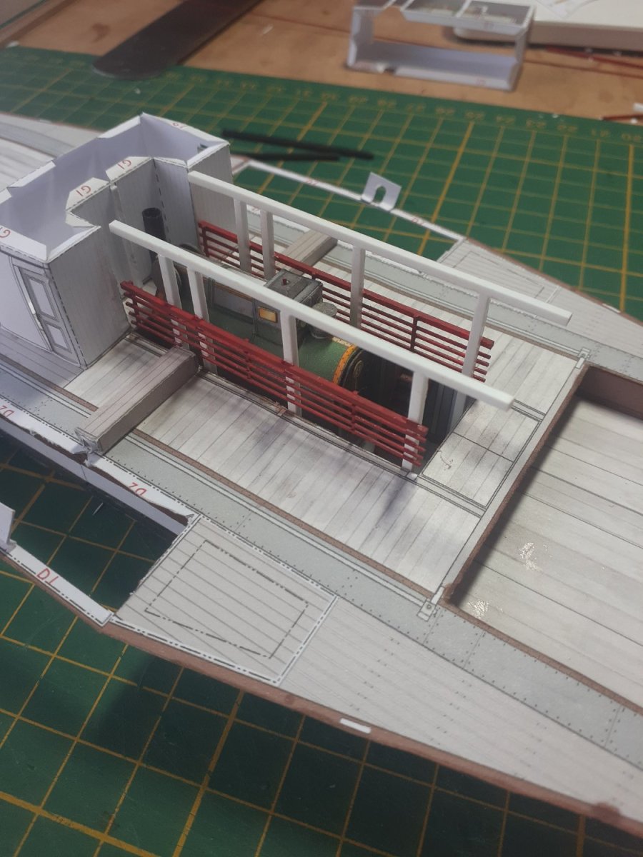
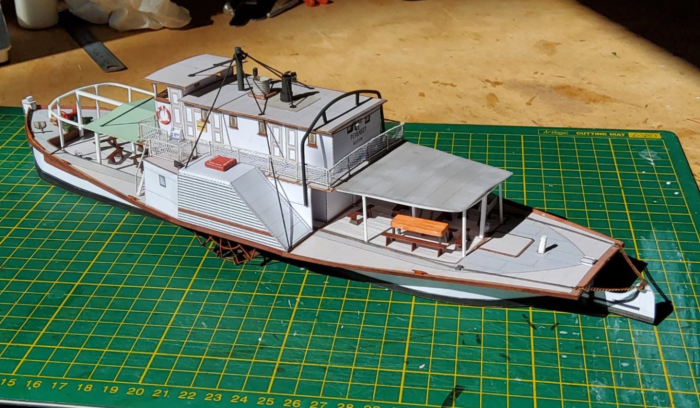
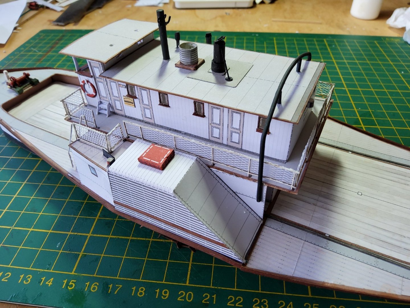
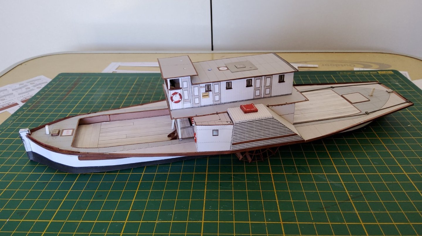
 Next thing to do is form, from styrene stock, the frameworks, fore and aft, that support the sunscreens. No particular problem, but a bit fiddly. The stays now have to be fitted. The two fore stays pass through the roof of the wheelhouse and through the sunscreen. The roof had points marked where the stays should go but the sunscreen didn't. Two templates were therefore used to locate the correct positions on the sunscreen for the required holes. The first template was chopped around until it fitted around the stays which were temporarily in position. This template was then used to give reasonably accurate locations for the holes on the second template and these were fine tuned and marked on the actual sunscreen. The stays were then fastened in position as was the sunscreen. The two aft stays presented a problem as they passed through the roof of the deckhouse and also the railing. No points were marked on the roof. The use of a template as I did for the fore stays was not an option, so a strip of card was used as a guide to finish with a best guess as to where the stays passed through the roof and the railing. Only one chance at this. Close but not perfect. The rudder was attached and I used the finest chain I had (instead of the printed option) to run from it to the rear of the deck. Finally, seats, tables, a barbecue and some buckets were added. The kit had some problems, nothing serious, occasional misidentification of parts. Some of the sheets were printed on both sides, but often the patterns didn't match, the rudder being an example. Instructions could definitely be better including more diagrams. Thanks for all the likes and the comments. Cheers


- 18 replies
-
- 9
-

-

-
- Pevensey
- World of Paperships
- (and 2 more)
-
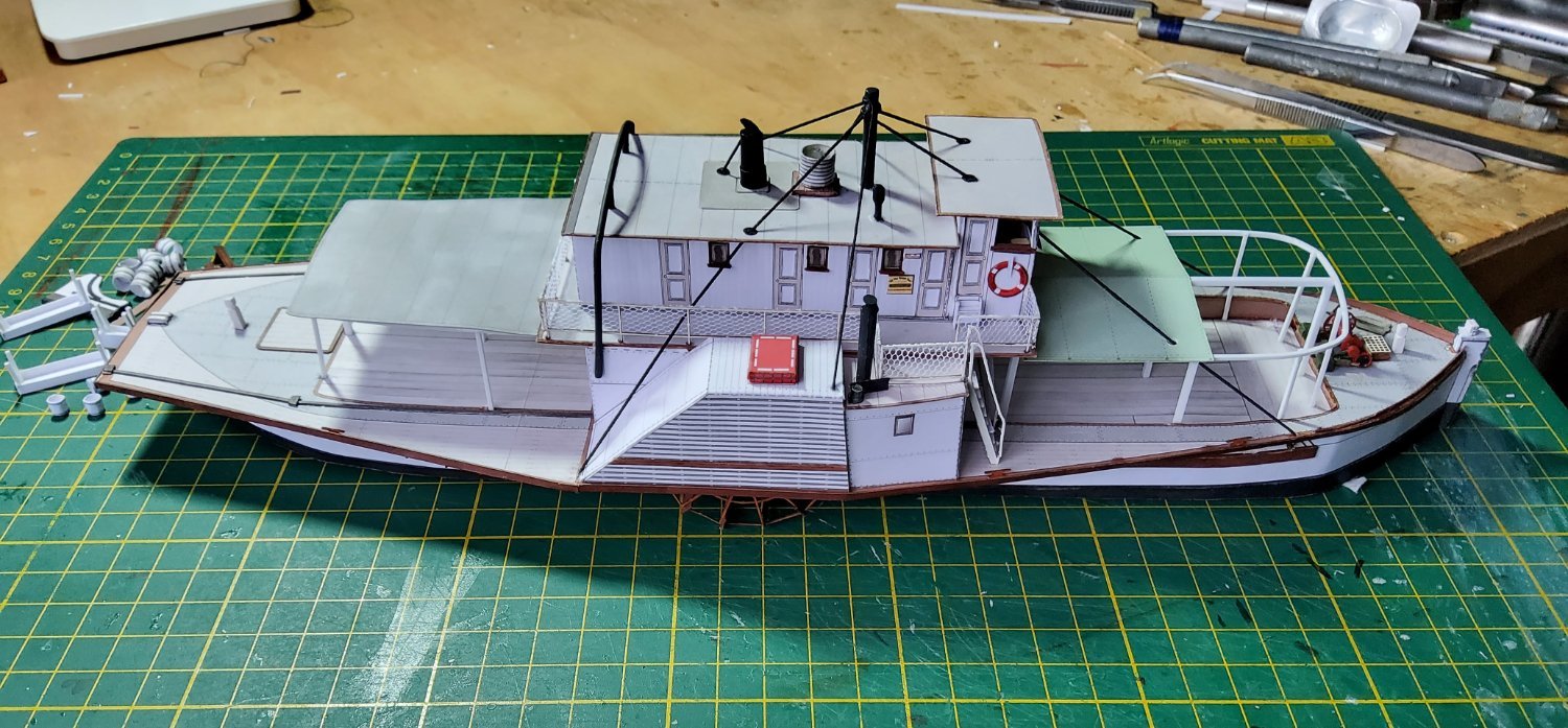
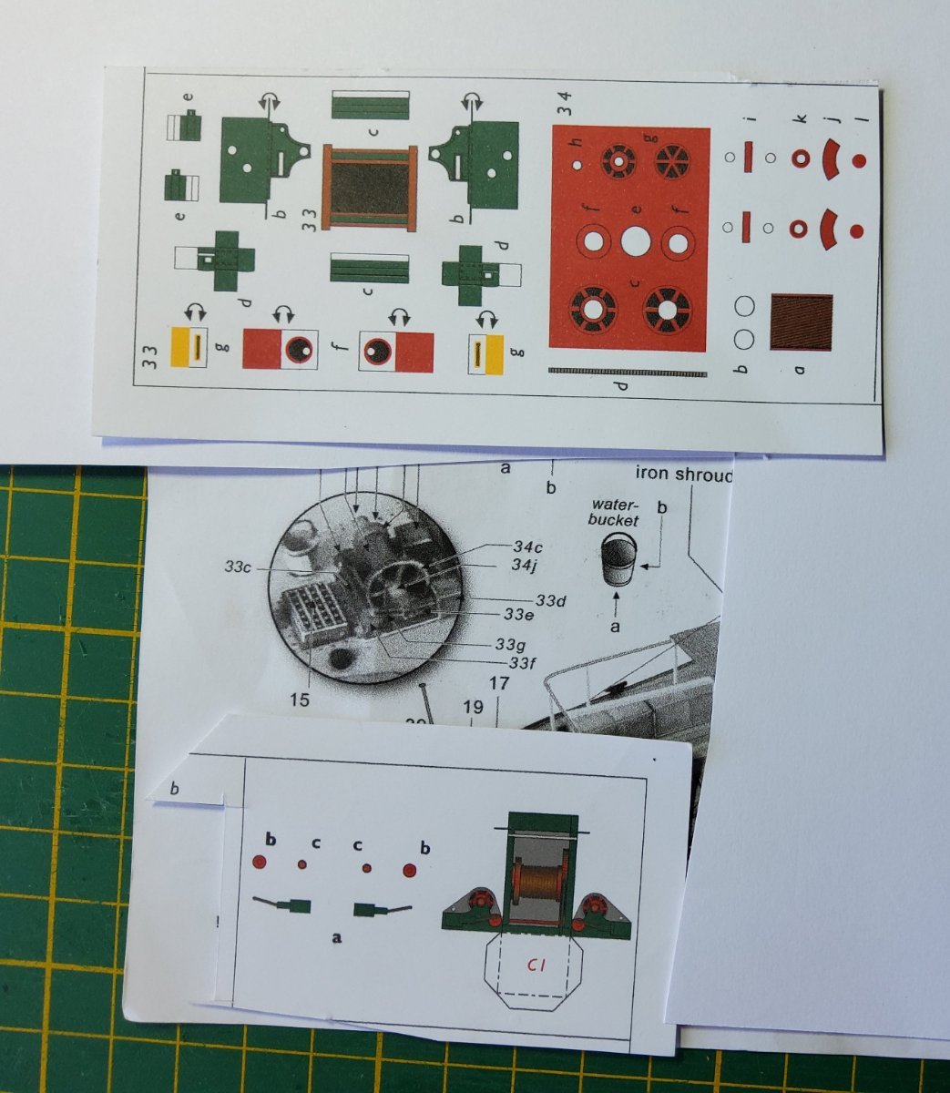
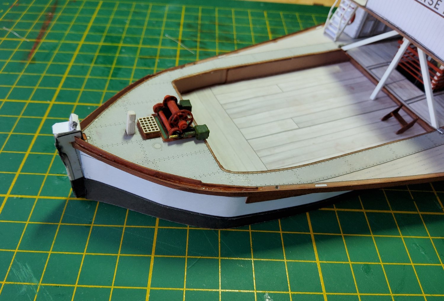
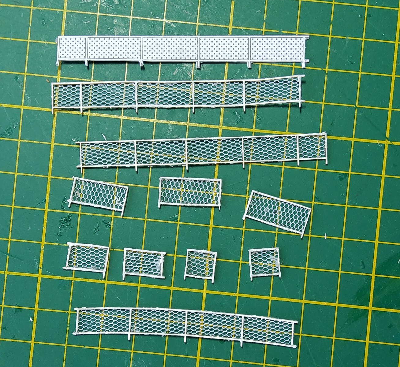
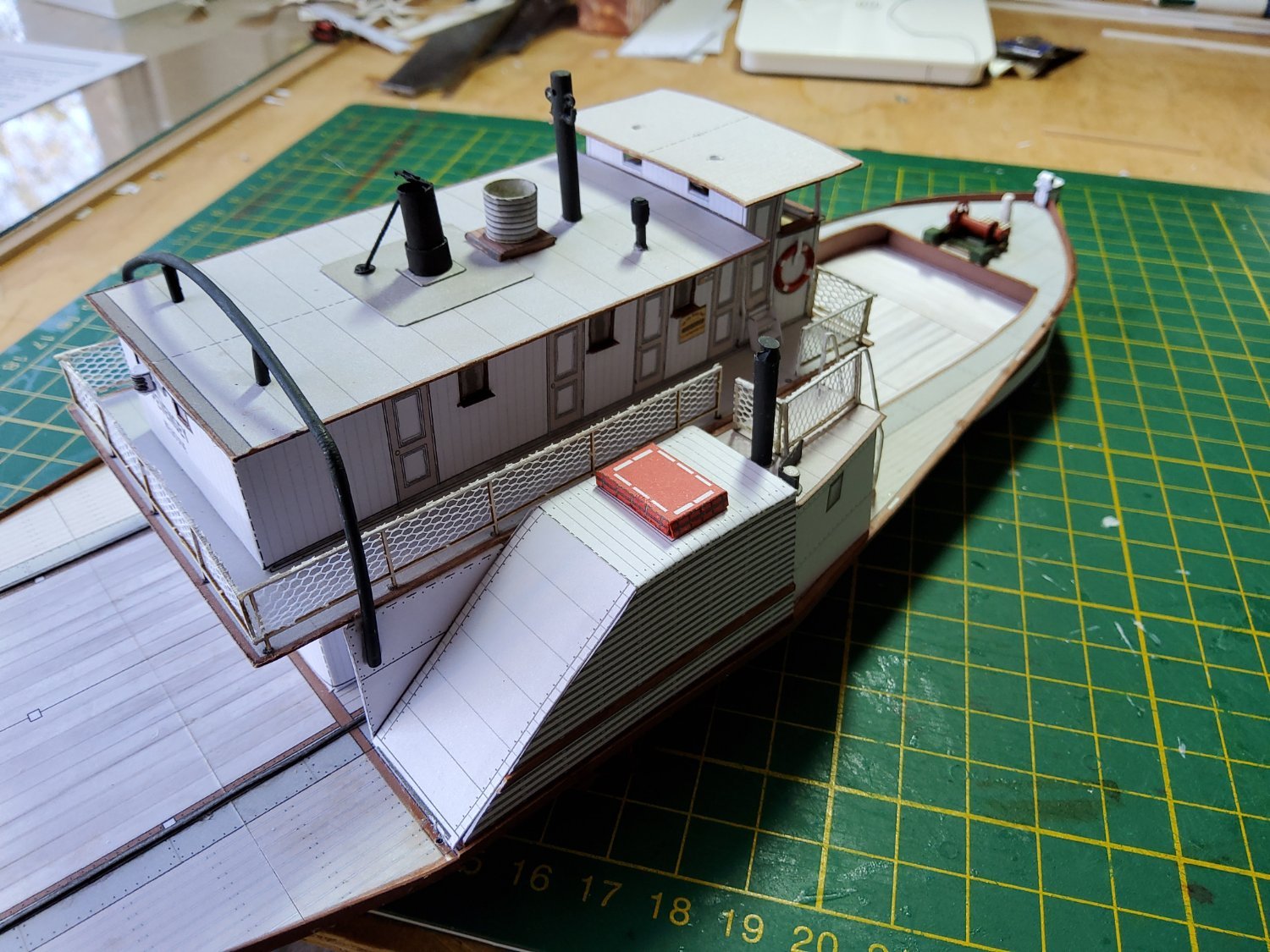
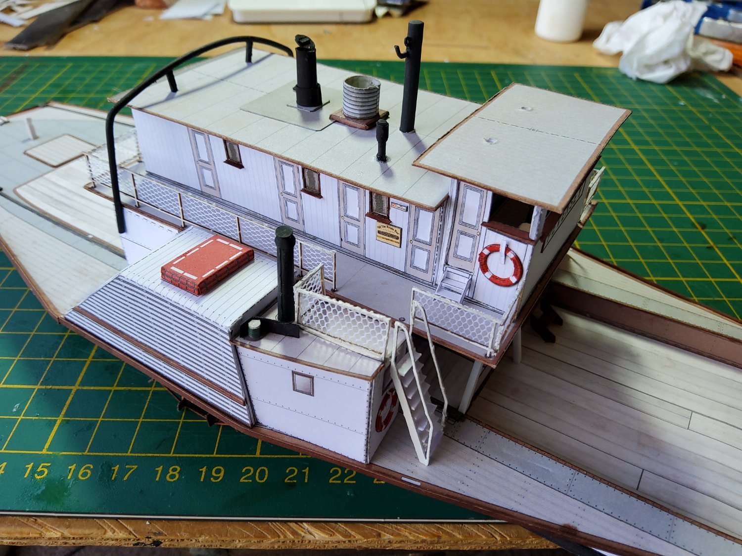
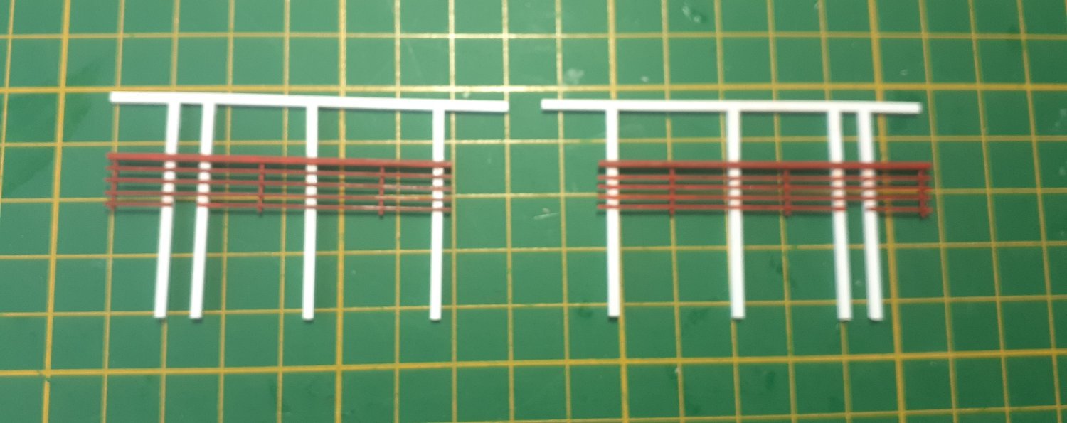
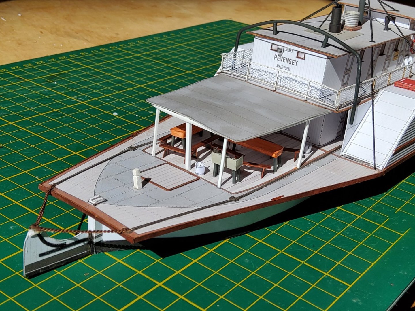
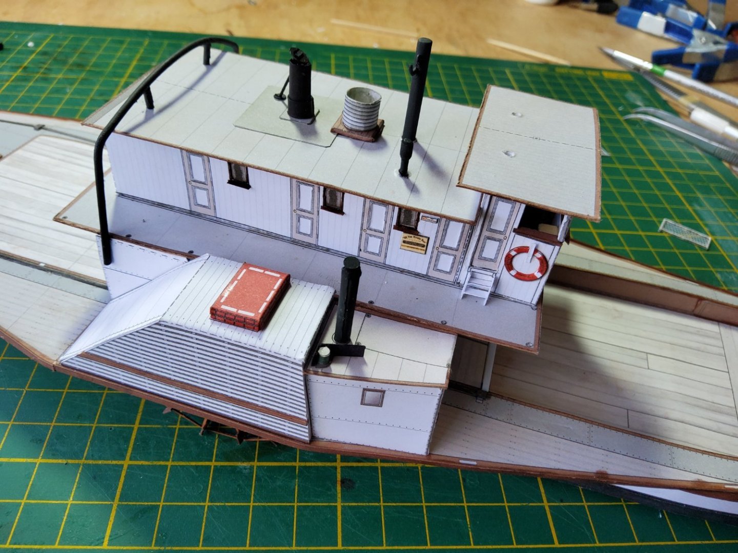
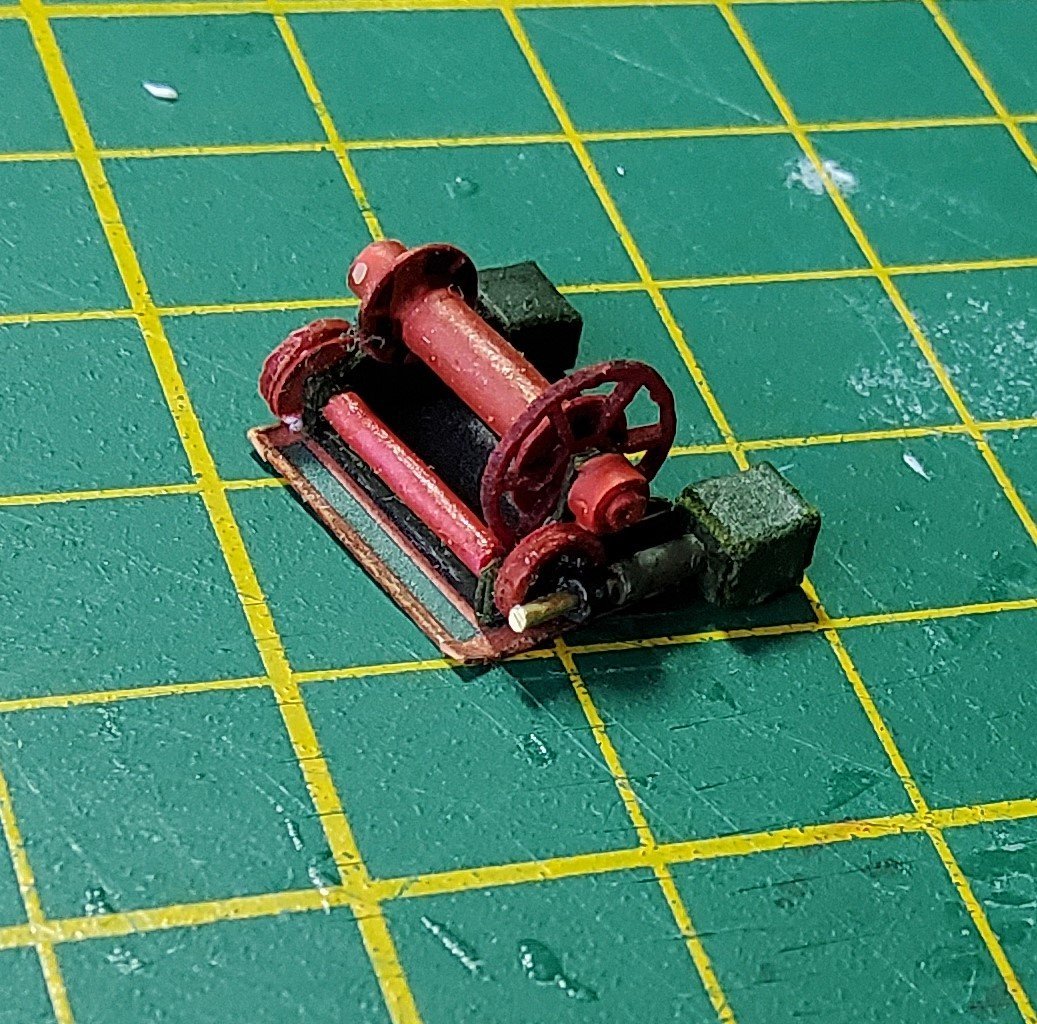
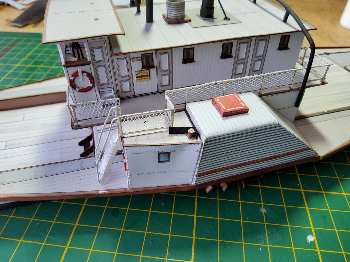
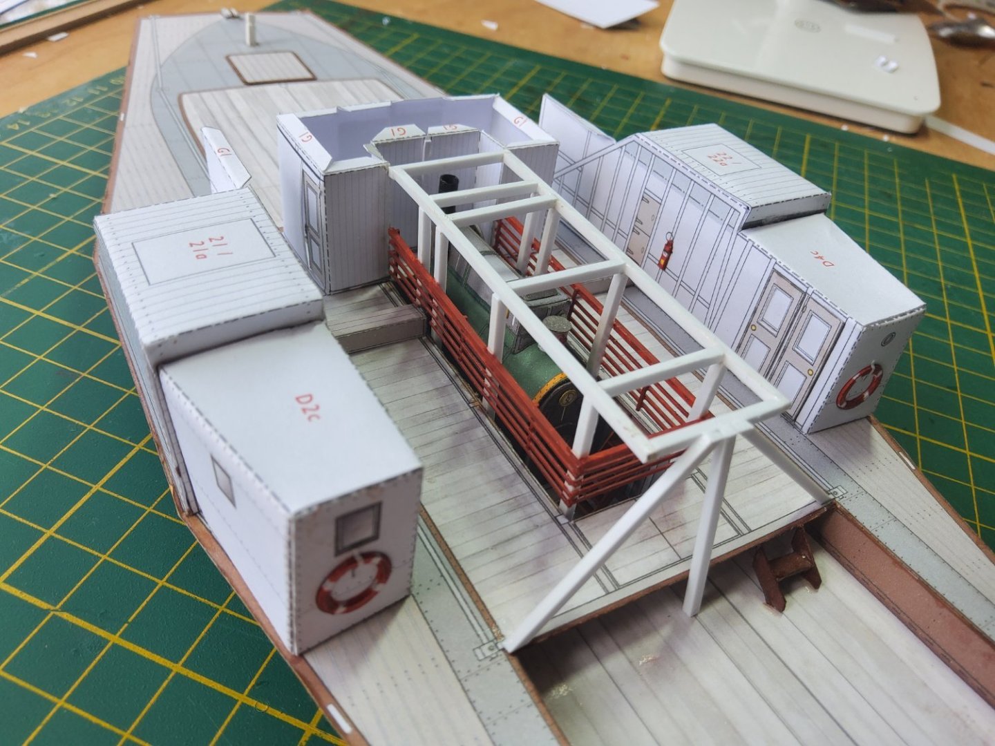
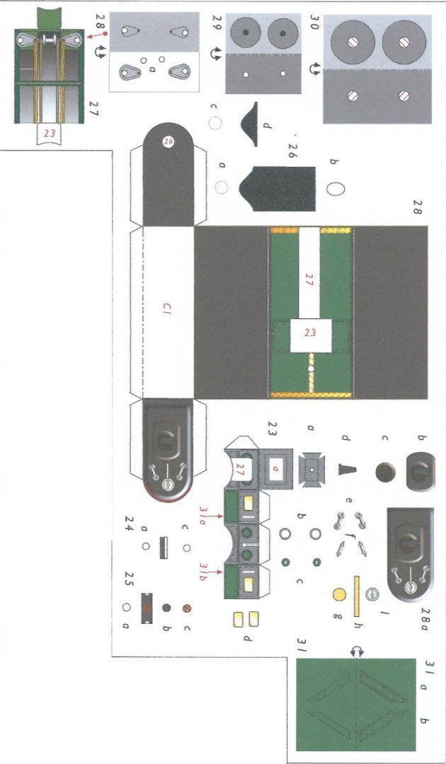
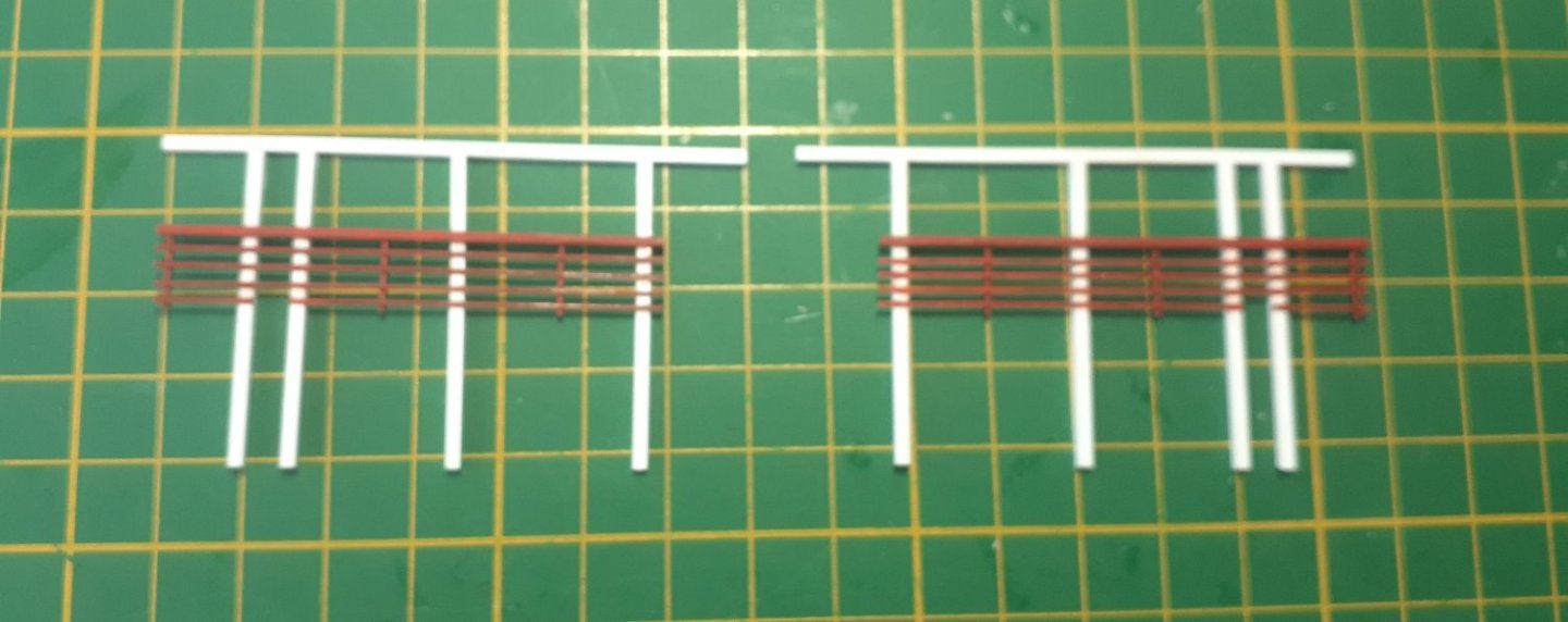
Various pieces added to the cabin - towing mast, funnel, chimney, whistle, nav lights, corrugated iron water tank and an iron bar across the rear of the cabin to provide protection from the towing rope (when used). Like other parts of the model, the winch can be made detailed (my choice) or simply. The image shows the parts for the detailed version at the top, the parts for the simple version at the bottom, and in between, the diagram is the only guide as to how the detailed pieces go together. Ah well. As I could barely make out that diagram, I decided to make a copy of the detailed pieces and attempt to put them together. It took some fiddling, but I did end up with a reasonable version, not quite as it should have been but close. I then built the final version, which looks very reasonable at normal viewing distance. Some styrene was used in place of card. Next, the railings. These were either printed or lasercut. I didn’t like the printed ones, so used the lasercut ones, and to represent the metal netting, I used some nylon net from the local fabric store. This was glued to the lasercut pieces, very carefully using gel CA, then trimmed. The railings were then glued in place, again using small drops of gel CA. The two ladders going from the main to the upper deck were assembled and glued in position. Cheers.


- 18 replies
-
- 7
-
-
- Pevensey
- World of Paperships
- (and 2 more)
-
MSW is extremely slow
Richard44 replied to Keith_W's topic in Using the MSW forum - **NO MODELING CONTENT IN THIS SUB-FORUM**
Hi Keith, I too am in Aus, and have had no problems with either uploading or downloading. Hope your problem clears up. Cheers -
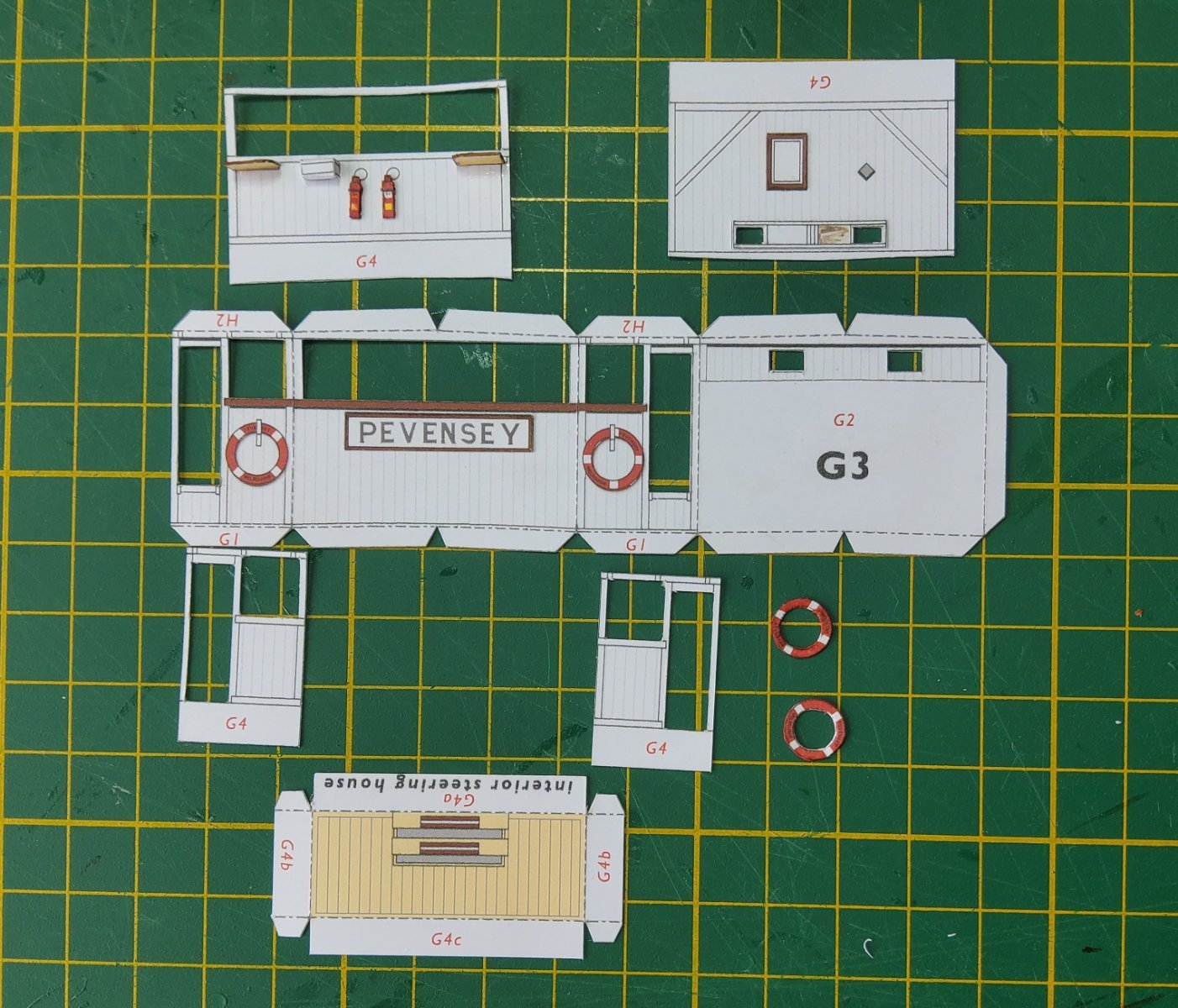
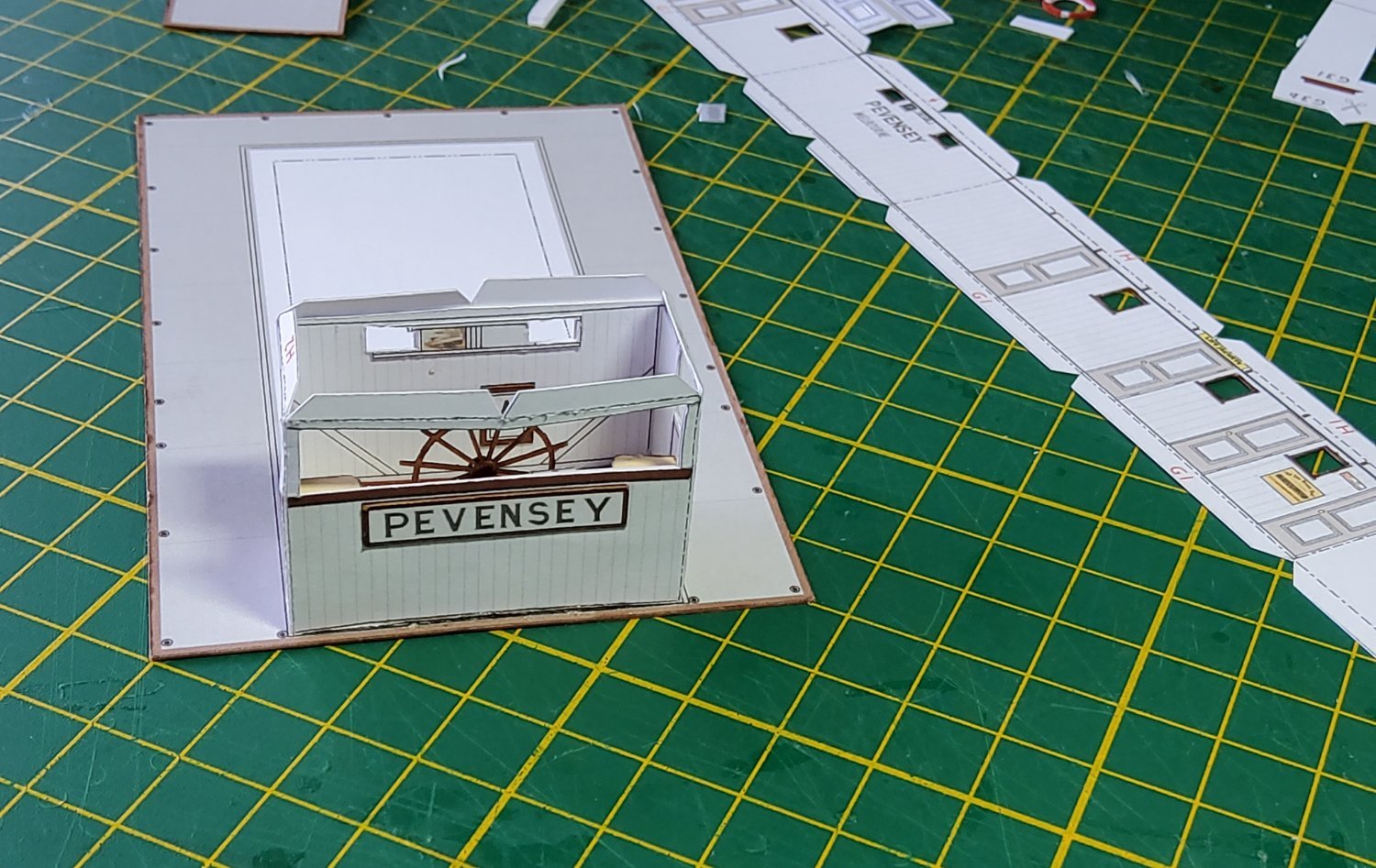
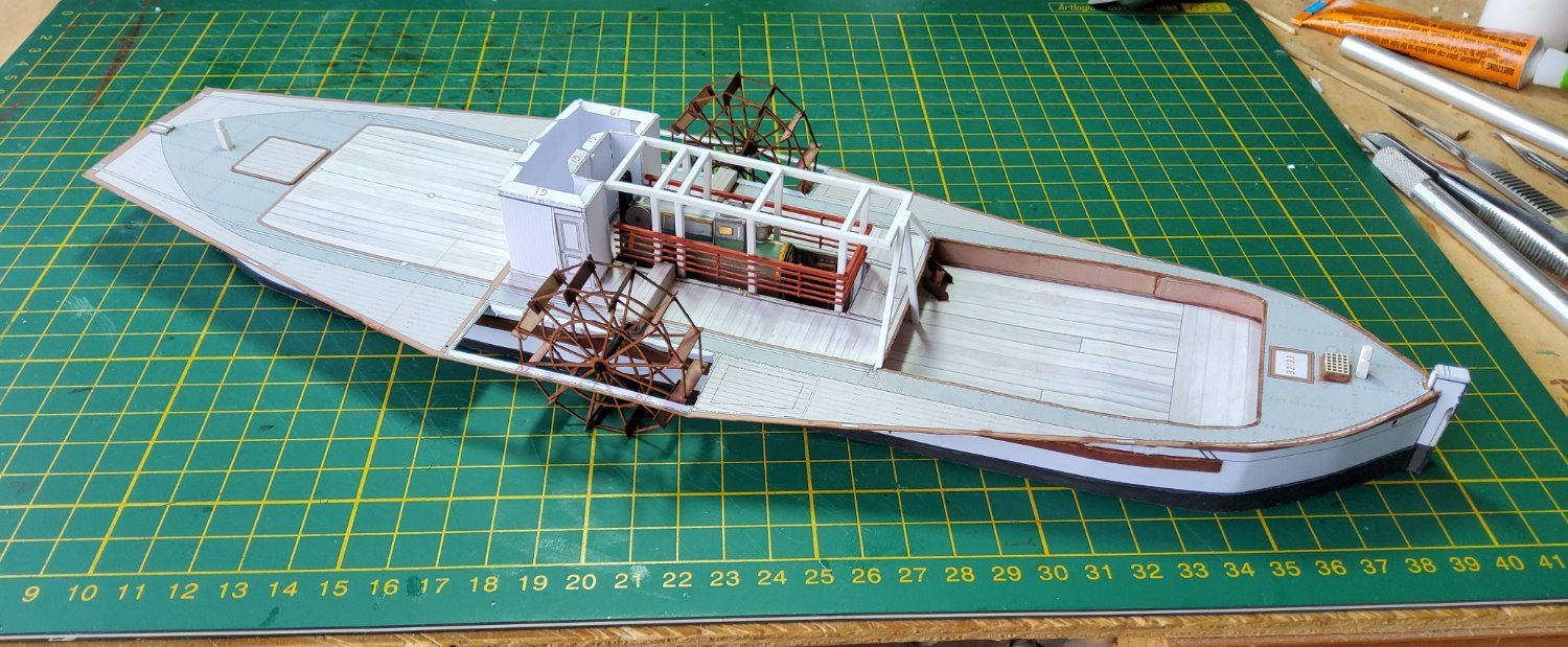
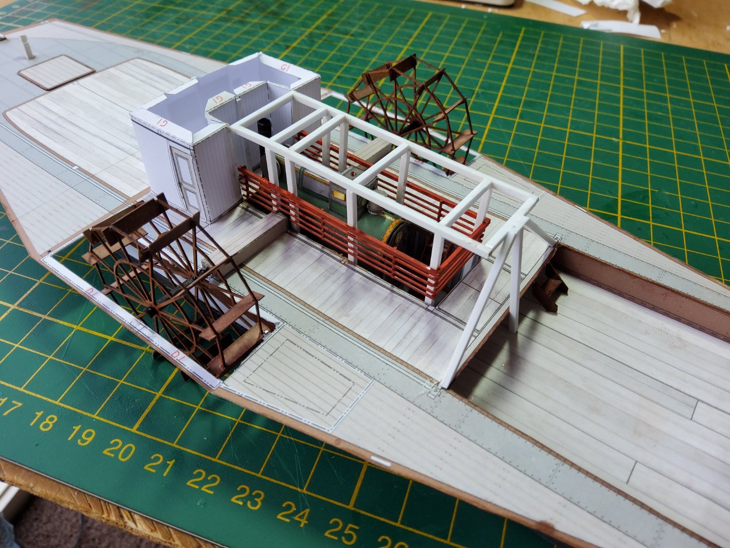
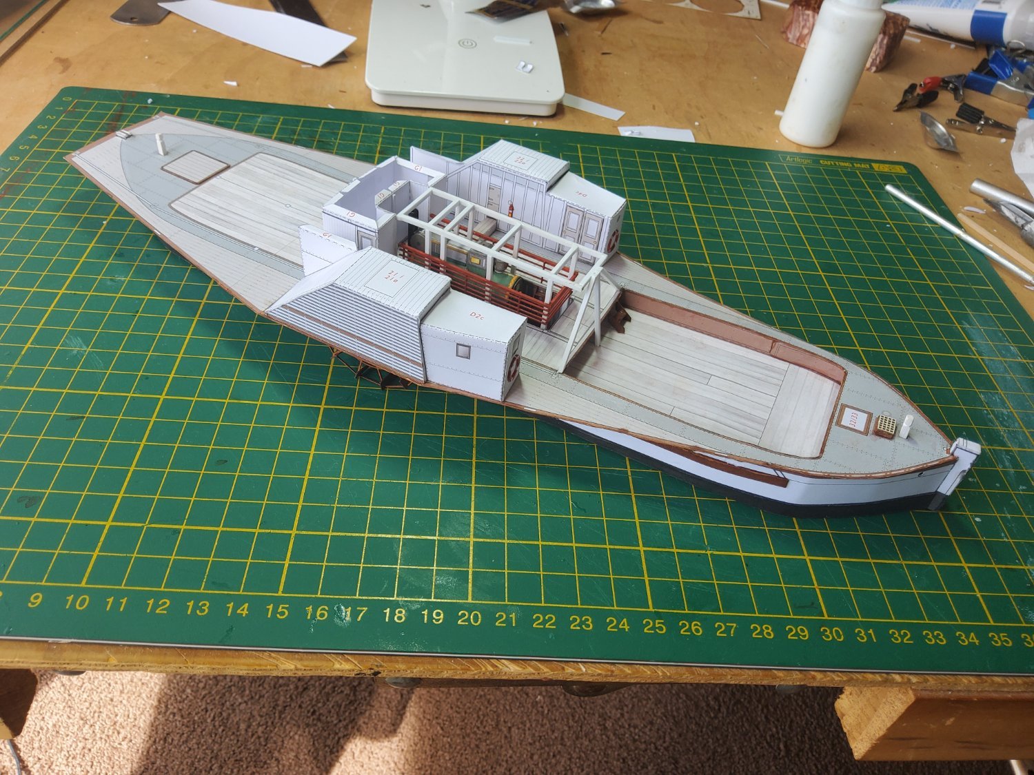
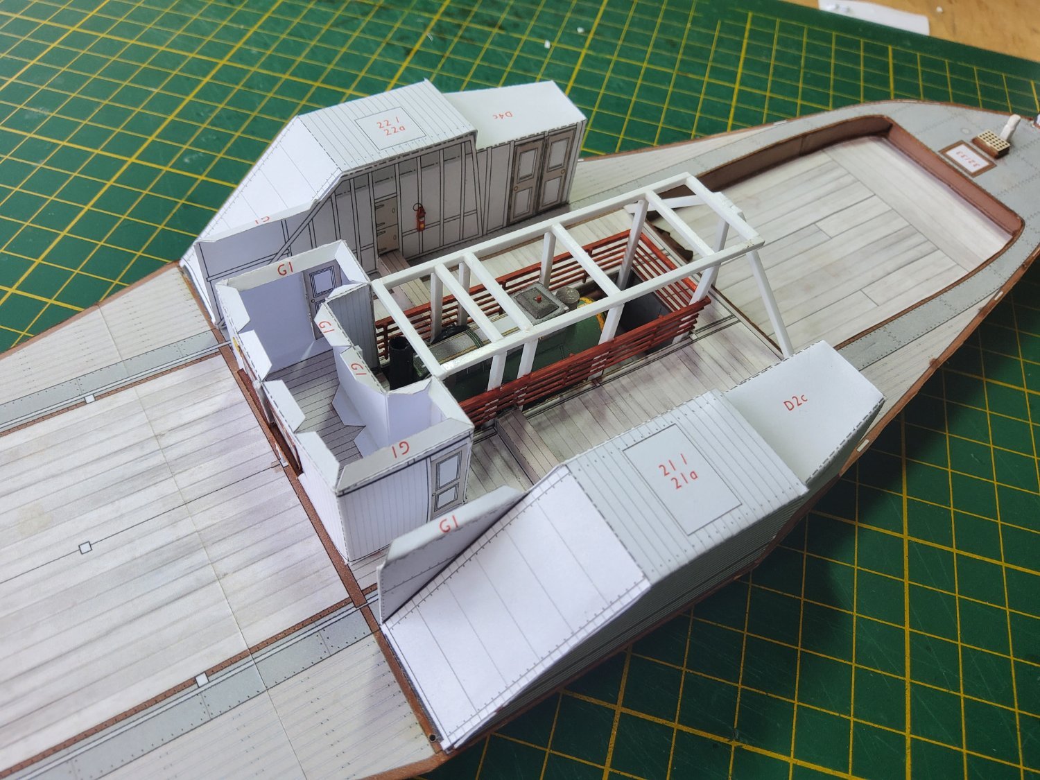
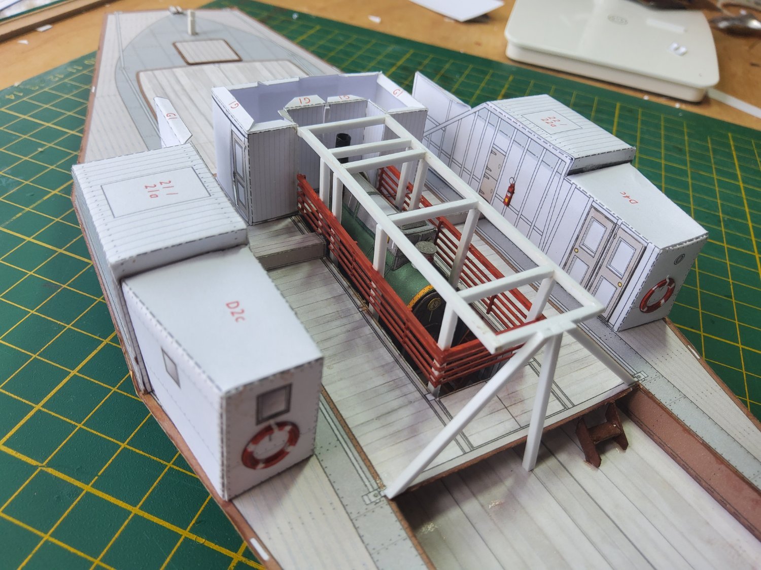
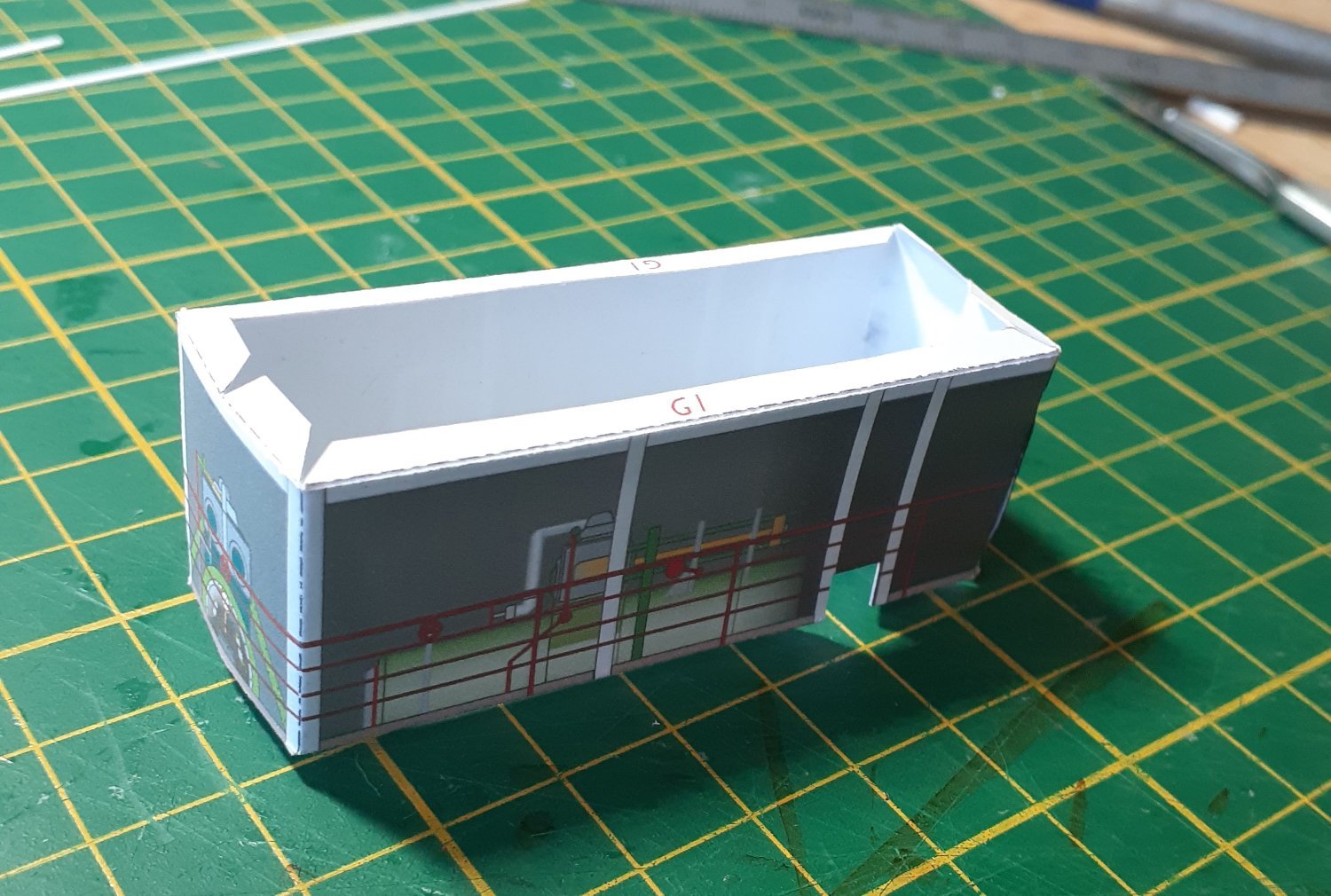
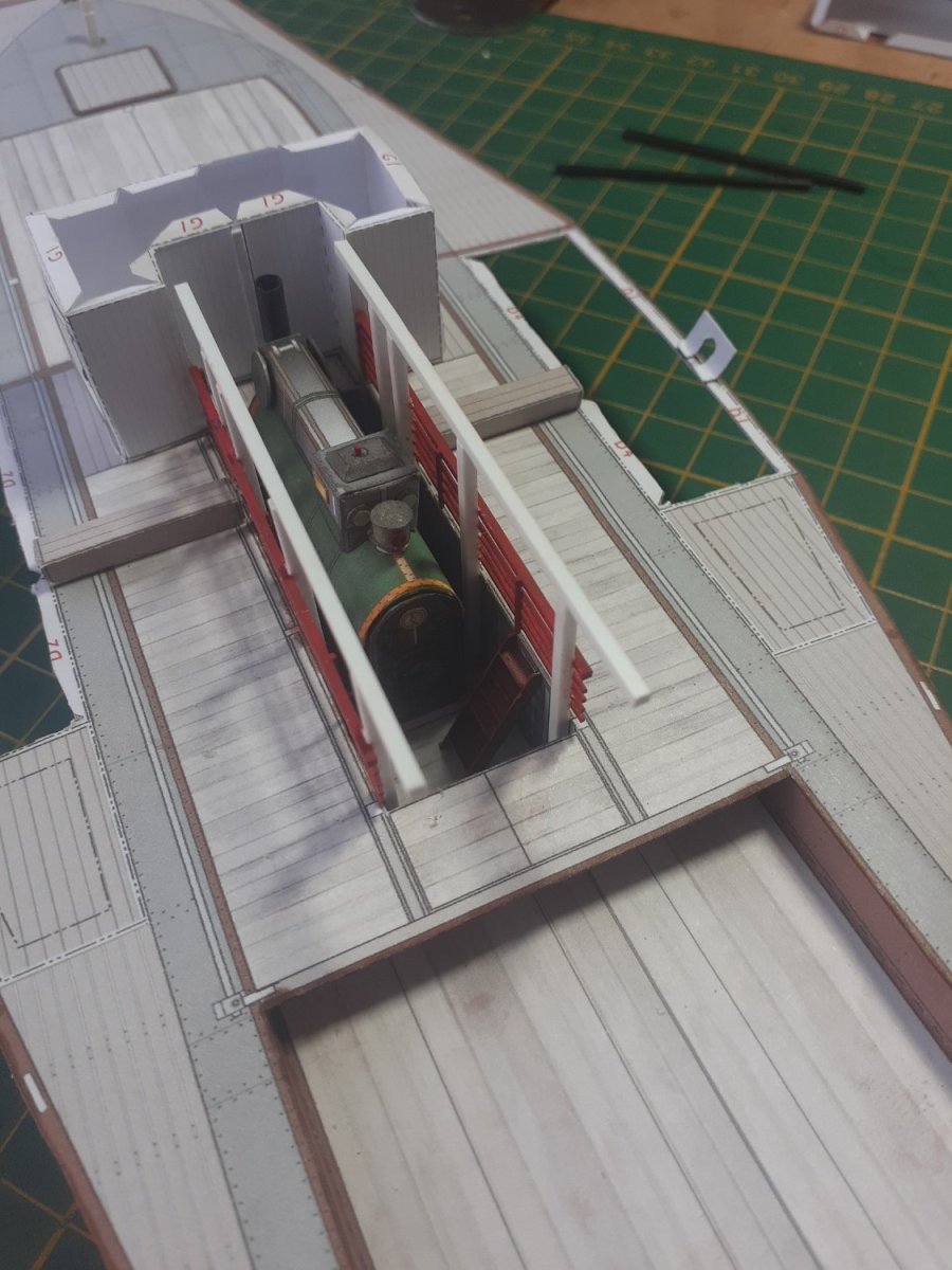
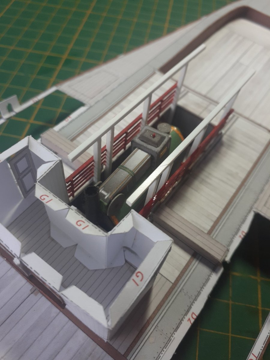
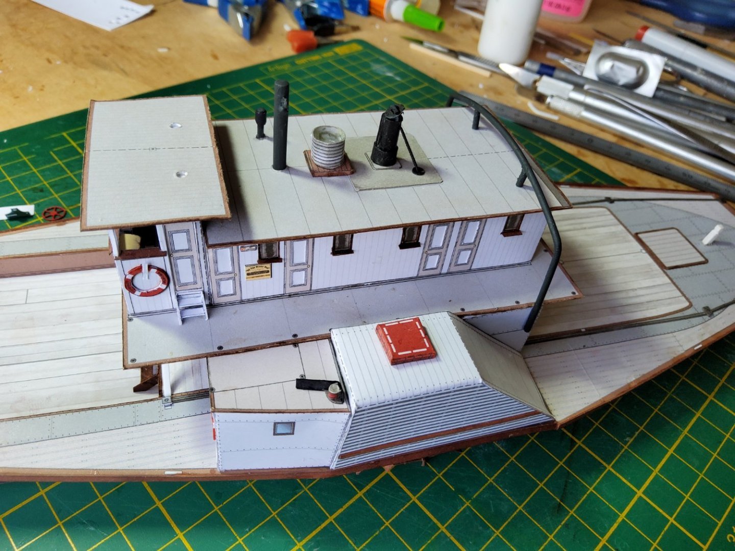
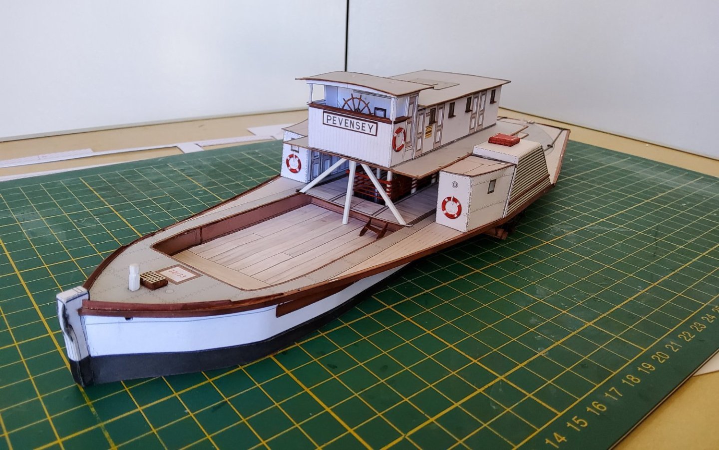
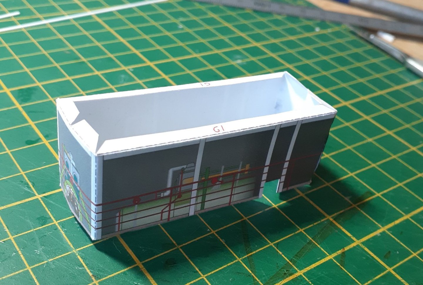
Thanks for all the likes . The parts for the wheel house. The instructions suggested that the main part of the wheelhouse (G3) be cut so that you would get four separate pieces - front, back and two sides. Then after gluing in place the internal details, glue the four pieces back together - seemed odd to me, so I didn’t. I simply folded G3 around the bottom (the yellowish piece) after adding the internal front and back doubled walls. The bottom was too small and some card had to be used to fill the gap between it and the walls. The completed wheel house, including a lasercut wheel, in place on the top deck. The passenger cabin was a simple unit, and it was glued to the top deck behind the wheelhouse, and this deck was then fixed in place, resting on the framework above and around the engine, and on the edges of the paddlewheel boxes. The engine is barely visible from the front and not at all from the sides, but I know it’s there! Cheers


- 18 replies
-
- 7
-
-
- Pevensey
- World of Paperships
- (and 2 more)
-
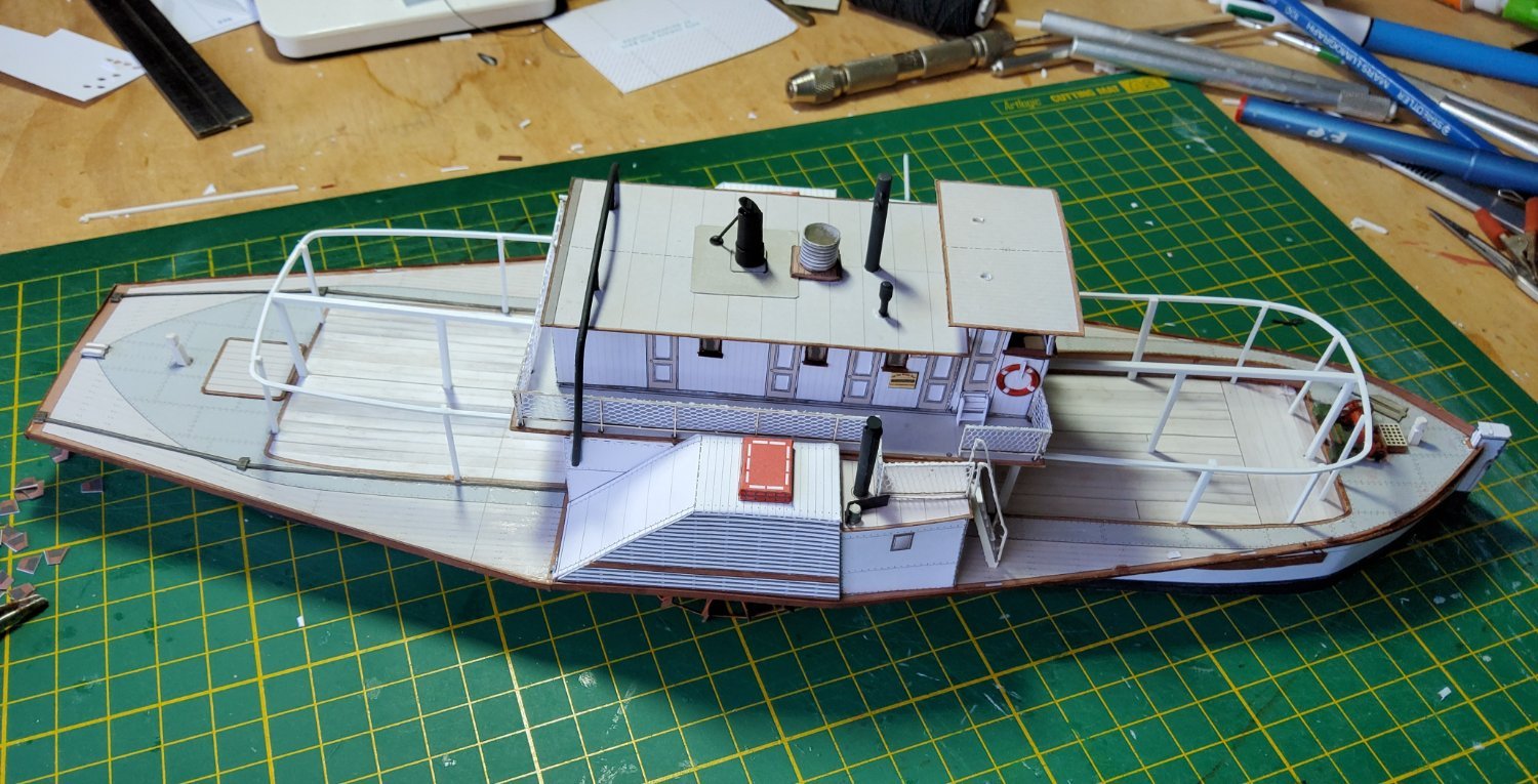
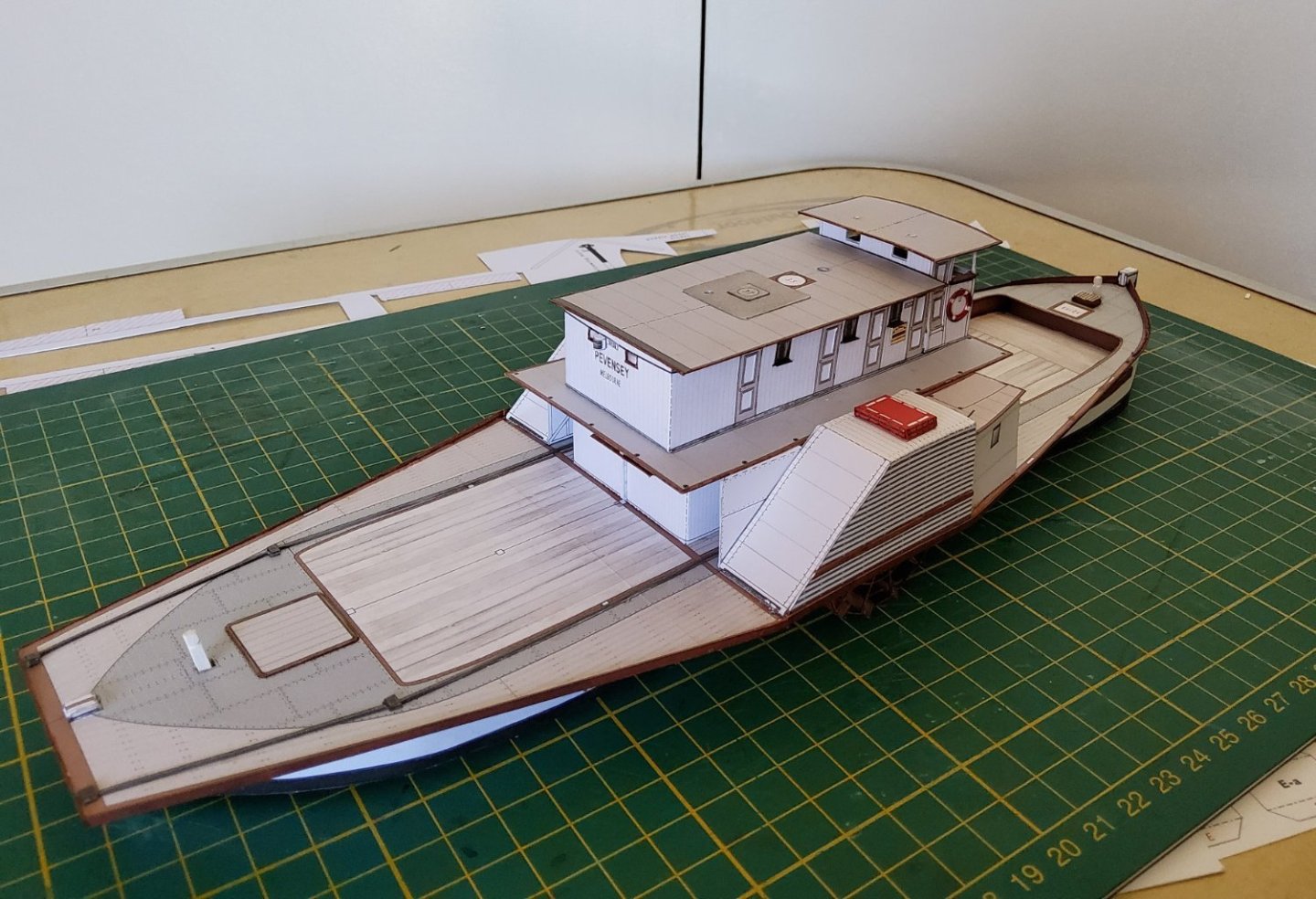
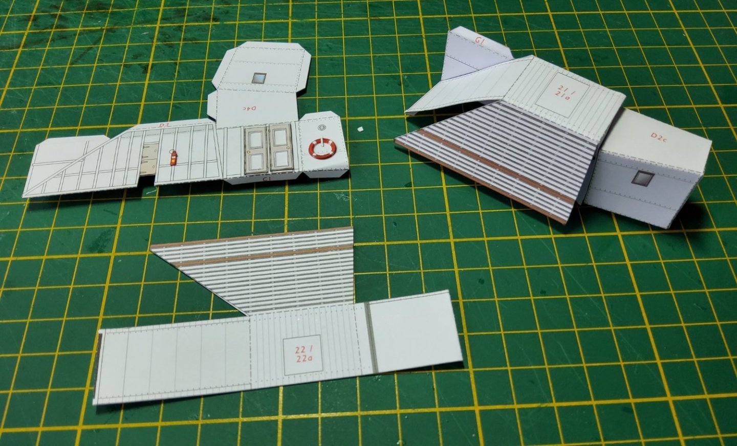
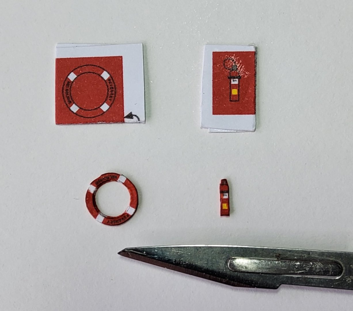
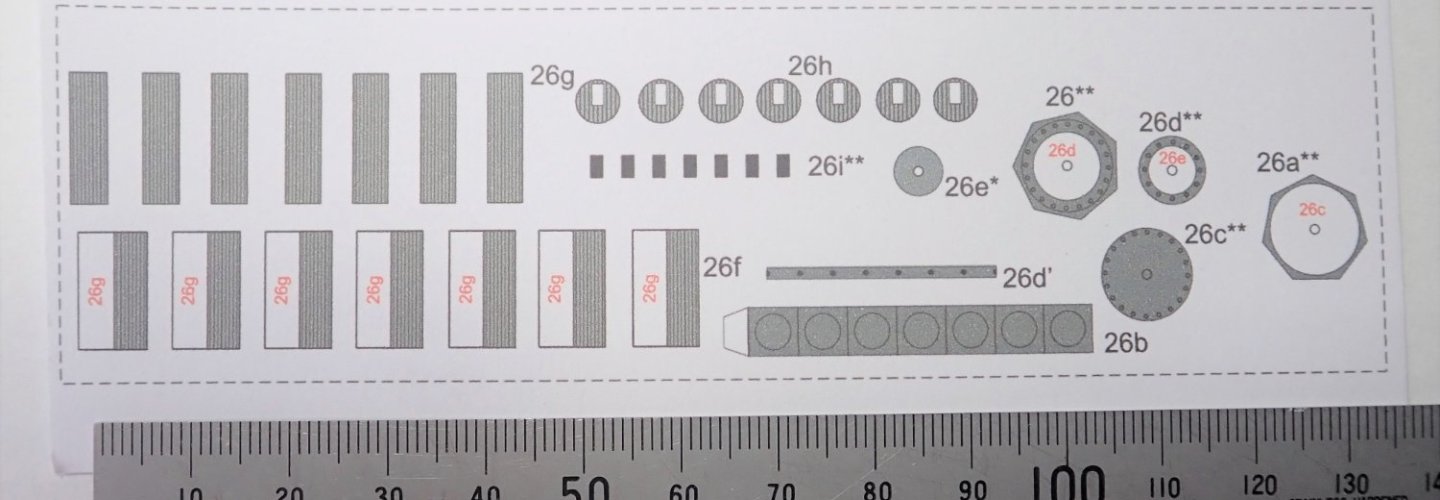
So, having sorted out the paddlewheels, time to fix them in place. The framework aound the engine space has also been completed. The kit provides extra doors etc so that these can be doubled to give some impression of depth. Two of the extras are the fire extinguishers and the life buoys (these actually have the boat’s name on them). This photo shows those as printed, and cut out, edge coloured and ready for mounting. Next are the boxes that cover the paddlewheels, only two parts each but multiple bends. The doubled fire extinguisher and the life buoy can be seen on one. Cheers


- 18 replies
-
- 6
-
-
- Pevensey
- World of Paperships
- (and 2 more)
-
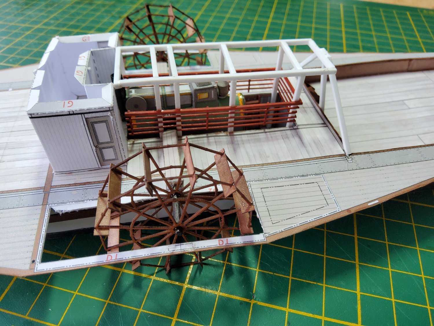
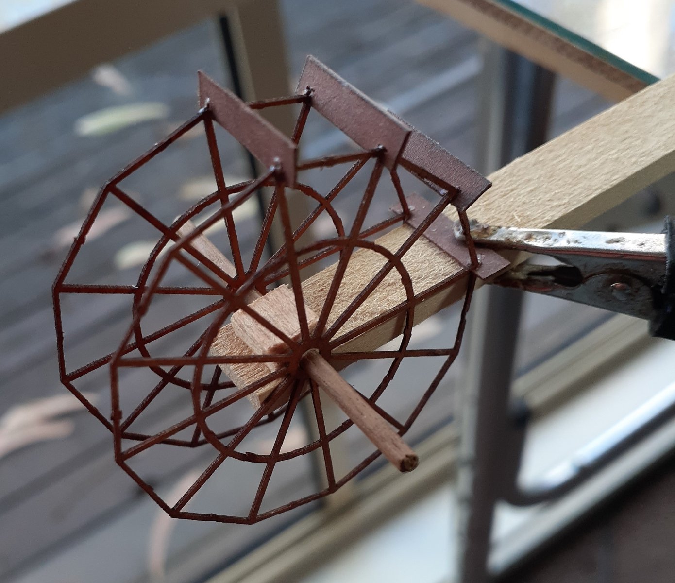
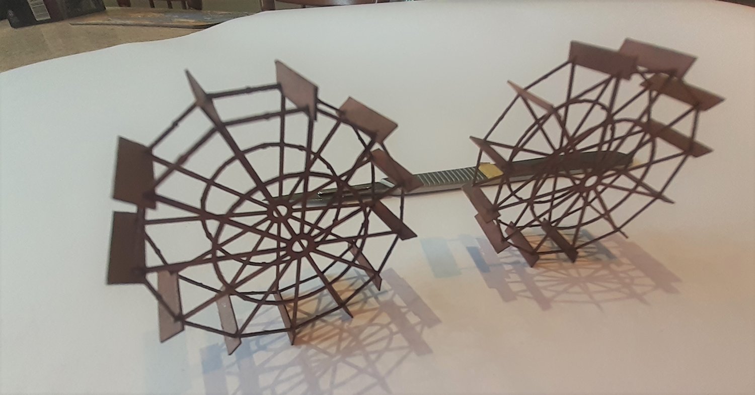
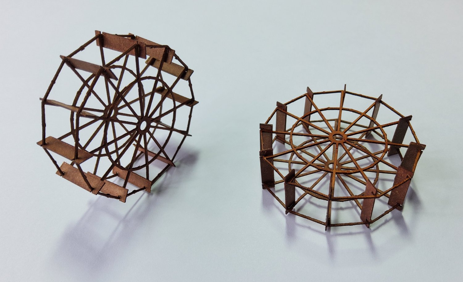
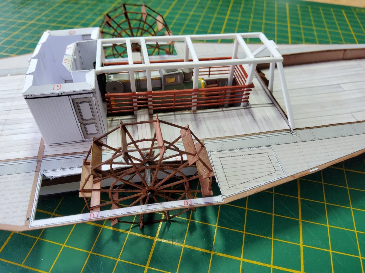
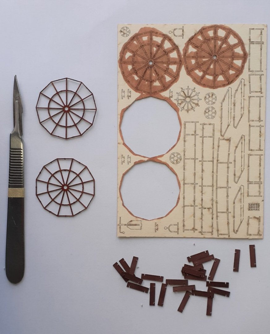
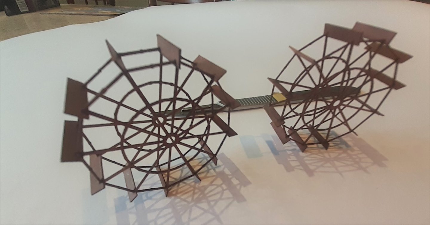
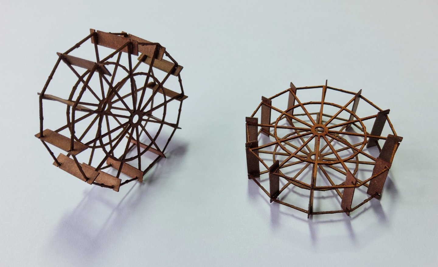
The paddlewheels could also be made as a simple version, or a more detailed version. I decided on the detailed version which has lasercut "wheels", rim, spokes and hub, plus card blades. These are all quite delicate, so to minimise the chances of damage while these were being assembled, a simple jig was devised to hold the rims in place while the blades were glued between them. This was successful and the completed paddlewheels looked very good. BUT, BUT, when I tried a test fit of the paddlewheels into the slots on the sides of the deck, they wouldn’t fit! 😖😖 What the…☹️. Everything seemed to have been assembled according to the instructions, but as I had decided to build the detailed version, I totally ignored the instructions, and in particular the printed parts, for the simple version. Big mistake 🥴, as if I had taken notice I would have seen that the blades needed to be inside the actual rim, rather than standing proud as I had made them. Now what 🥴. Trimming the blades flush was not an option, as most of the blade would have been removed, and damage was almost guaranteed. If they had been made of wood I could probably have de-glued them using isopropyl alcohol, but the fragility of the wheels and the unknown effect of the alcohol on the lasercut material suggested this was not going to work - I did try and it didn't. I therefore got in touch with Jeroen from World of Paperships and he very kindly sent me a replacement lasercut sheet free of charge 🙂🙂. So, paddlewheels, second attempt. Cheers

- 18 replies
-
- 7
-
-
- Pevensey
- World of Paperships
- (and 2 more)
-
Hi Andrew, No, not much chance of seeing much once the superstructure goes on. A lot of models, ships/boats, aircraft, whatever, seem to have a lot of hidden detail that only the builder knows about. Sort of the modeller's curse - do I add that bit that will take much patience and a fair amount of time, knowing full well that no-one will ever see it. Ah well, it is a hobby 😁. Cheers
- 18 replies
-
- 3
-
-
- Pevensey
- World of Paperships
- (and 2 more)
-
Thanks for your comment B.E. I've visited Echuca quite a few times, firstly about 20 years ago. I thought then that I'd like to make a model of one of the paddle steamers, but no models were available.
- 18 replies
-
- 1
-
-
- Pevensey
- World of Paperships
- (and 2 more)
-
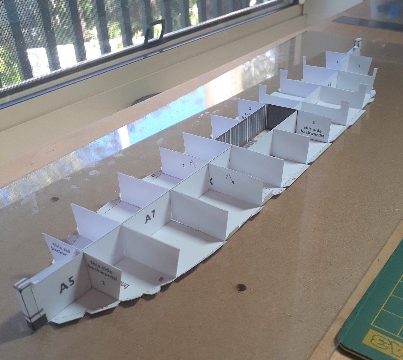
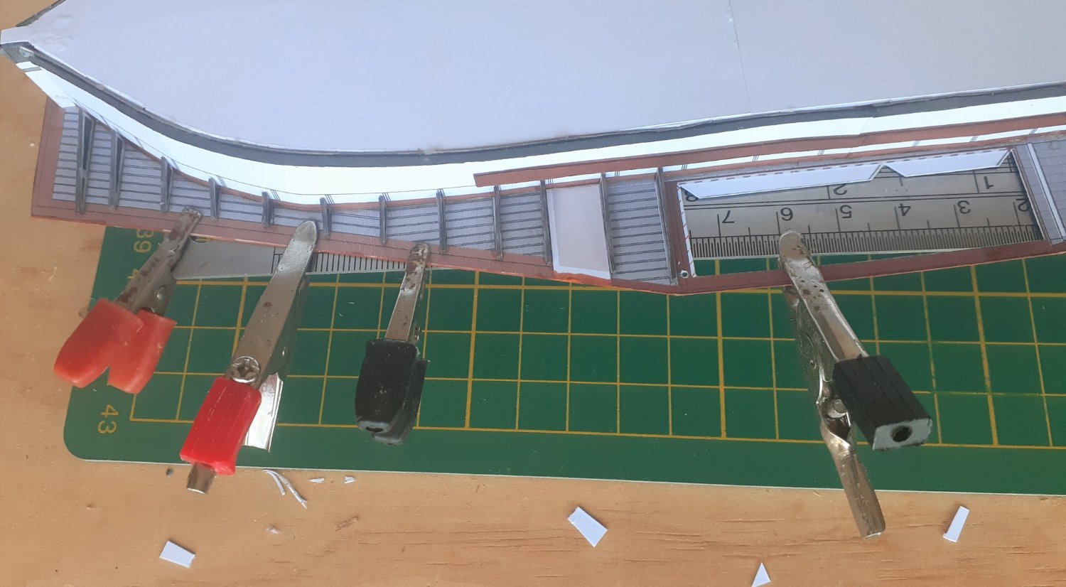
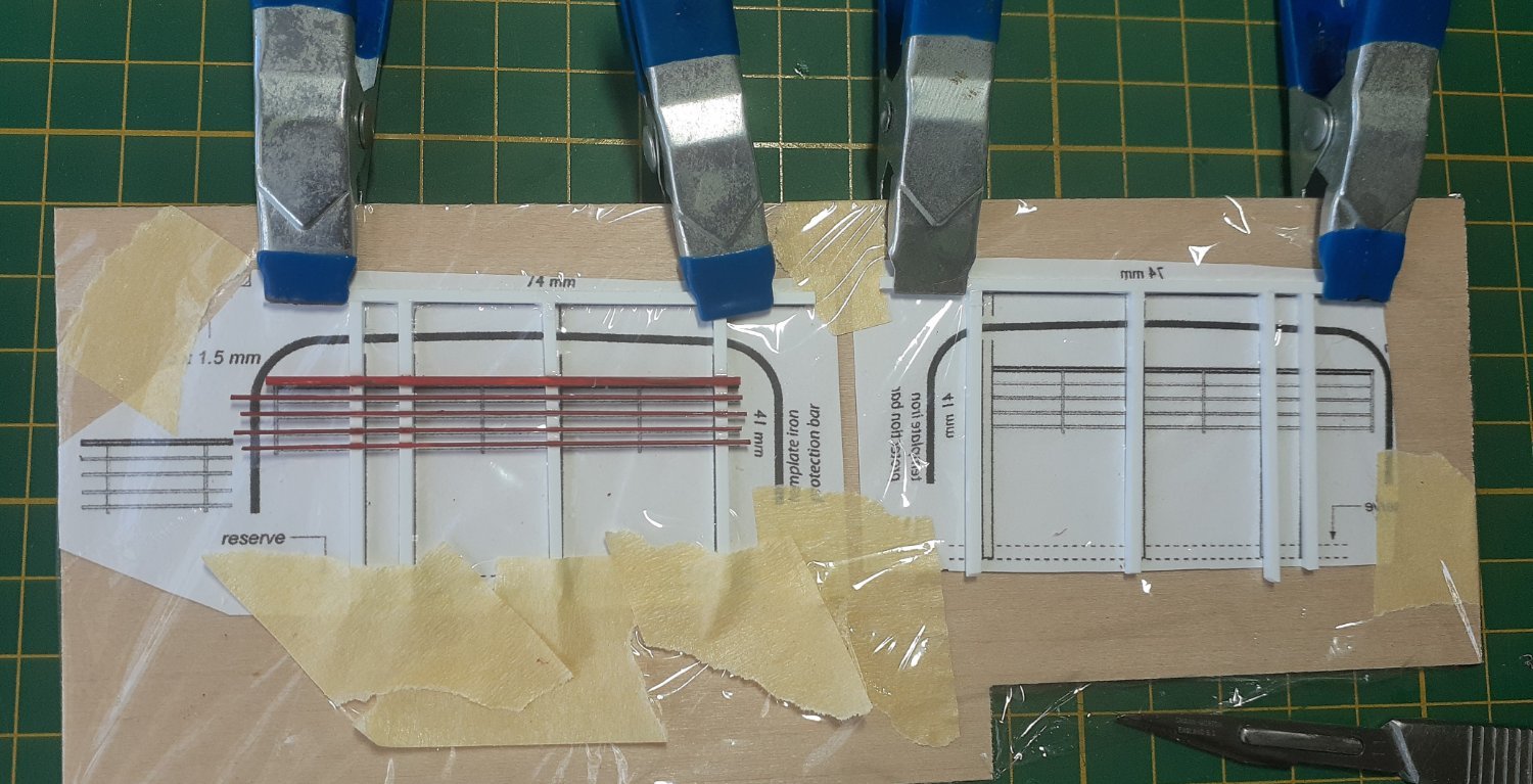
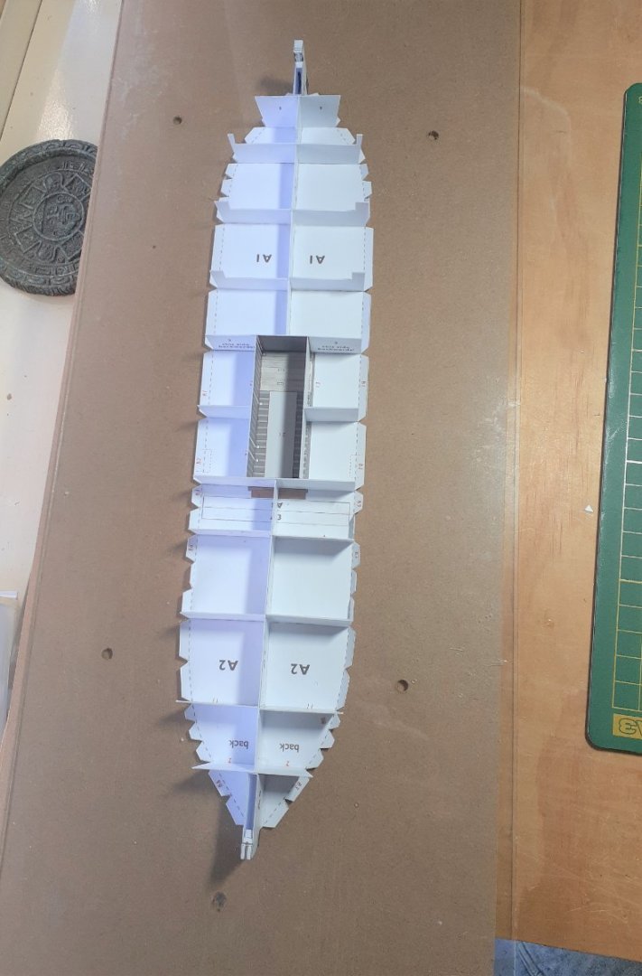
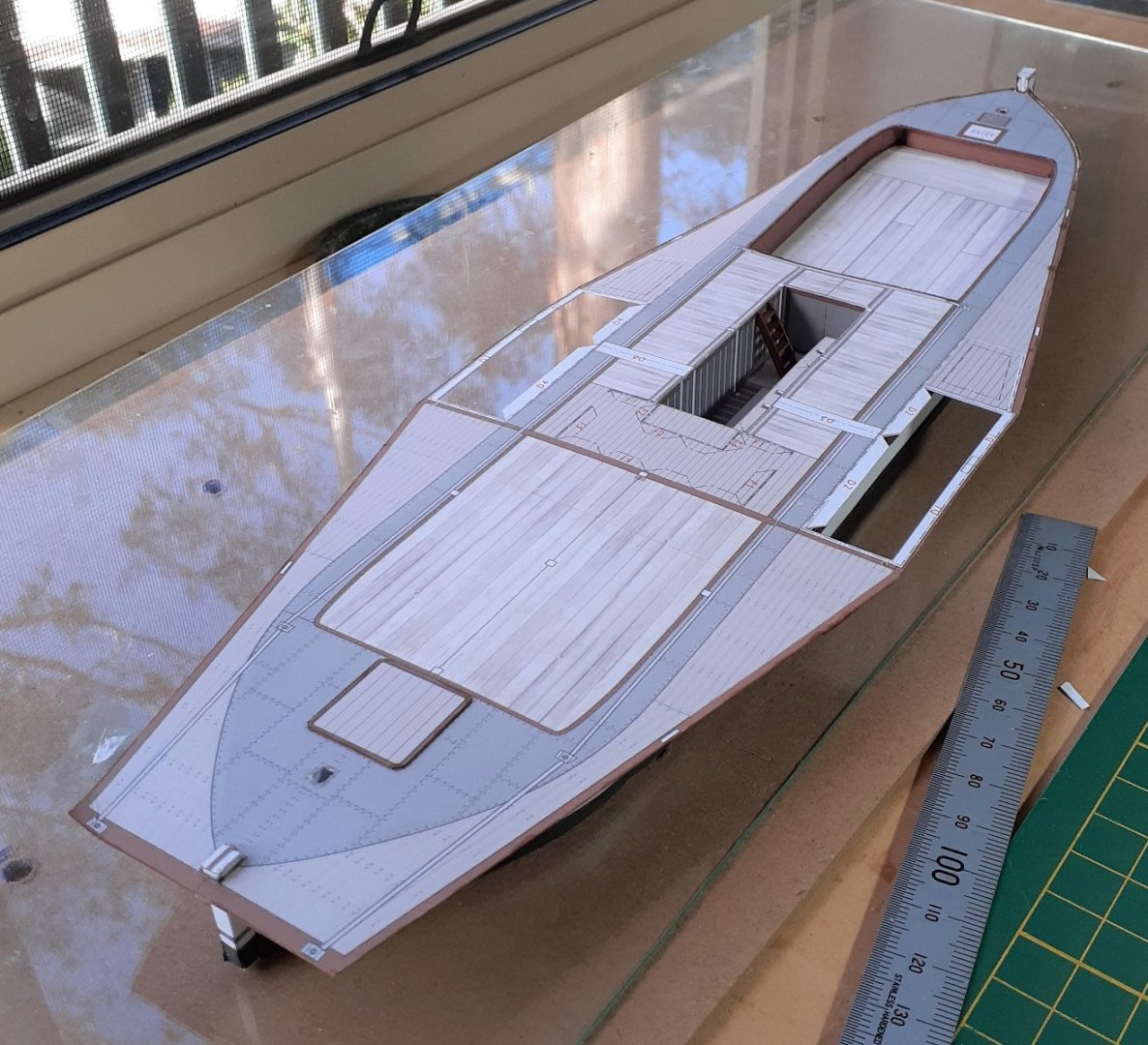
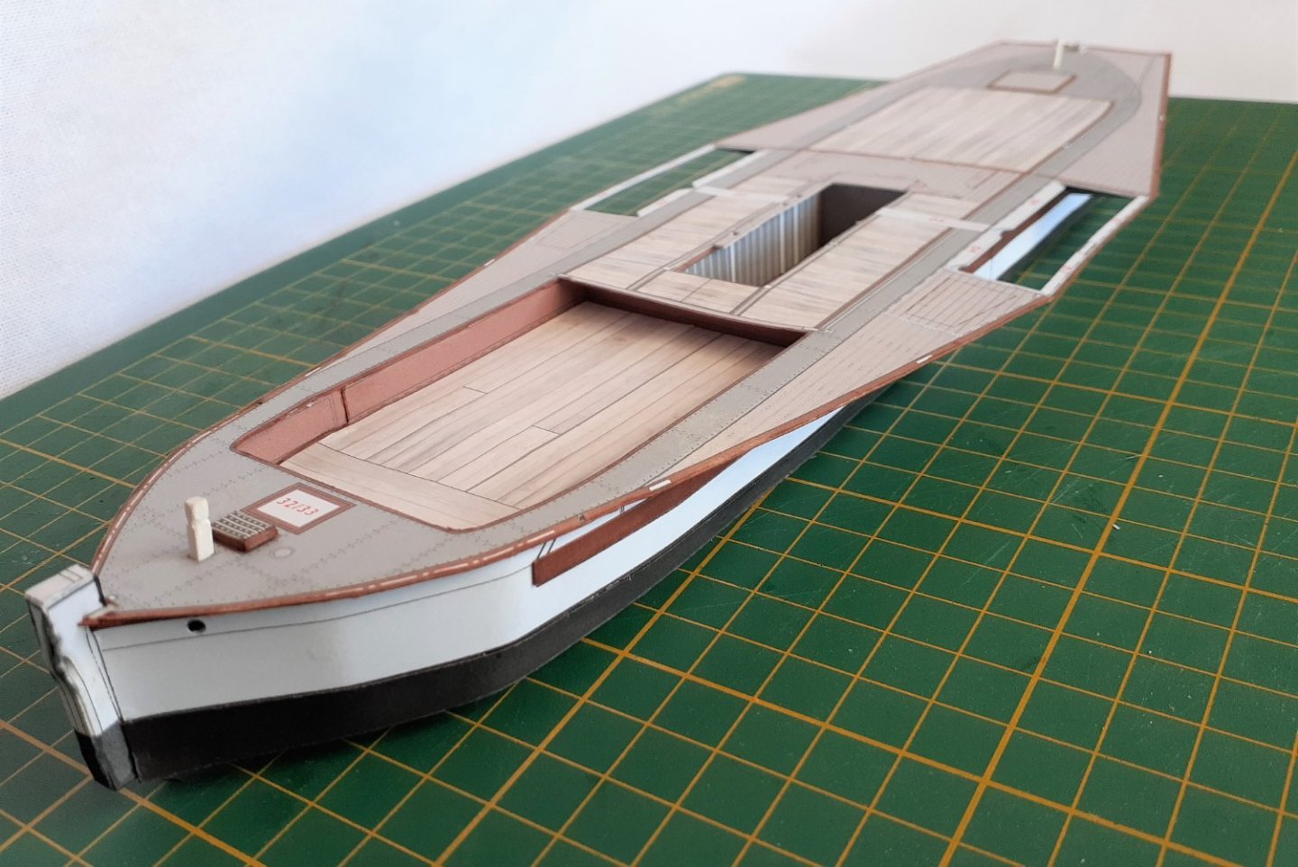
The paddlesteamer Pevensey was built in 1910 at Moama on the Murray River (Australia), as the non-powered barge called Mascotte, but in 1911 the vessel was equipped with a steam engine and renamed Pevensey. This turned it into one of the largest towing boats on the Murray, and it itself was capable of carrying 120 tons of cargo. In 1932 she was almost destroyed by fire, was rebuilt in 1933-35, ran a regular cargo run in 1939, but was then made redundant and tied up at Mildura. In 1975 she was slipped at Moama and completely restored. A 1983 Australian TV series called "All the Rivers Run" starred her as the PS Philadelphia. The Pevensey is now based at Echuca and runs tourist trips along the Murray. The kit from World of Paperships (from the Netherlands) has two sheets of general information (with some photos), one sheet of diagrams, four sheets of English instructions, five sheets of printed parts (some sheets are printed on both sides) and one small sheet of lasercut parts. The sheet of diagrams is complex and in places difficult to follow, hopefully this won't cause problems later. The bottom of the hull was tacked to a sheet of glass to act as a building board for the initial stages of the build. Two dabs from a glue stick sufficed for this. The sides were glued to the frames and the rubbing strakes added (forgot to take photos at this stage) then the deck was fixed in place. A portion of the foredeck had been removed and a replacement glued lower down to represent a shallow cargo hold. A cutout was also made to allow for the engine space. There are triangular supports between the underside of the deck and the sides. To ensure that the deck did not develop any waviness, a small steel rule was clamped to the top of the deck (the hull was off the glass and upside down for this step) while the supports were glued in place. Many of the parts of the boat could be made either as a simple version or a detailed version. This photo shows the simple version of the engine and its surrounding safety railings, folded up from the provided card print. The detailed version has 40 parts... ....and is the one I built. Unfortunately, I've somehow lost/deleted the photos I took of the completed engine, standing alone. A template was provided to allow construction of the main framework that is around the engine space, and it, and the safety railings, were made from 0.5, 1.0 and 1.5 mm square styrene stock. The framework supports the base of the superstructure that will be above it, and so had to be carefully fitted so that it was flat, even and of the correct height. Temporary "scaffolding" of wood strips and folded card was put in place to achieve this. The engine, engine space and surrounding framework (the latter is not quite complete). There is a small crew cabin just aft of the engine space. Cheers


- 18 replies
-
- 7
-
-
- Pevensey
- World of Paperships
- (and 2 more)
-
Thanks for your comments Egilman. My short build log has turned into a very interesting history lesson. 😁
-
Duh, stupid autocorrect. And I didn't see it even when proofreading! I'll correct it. Cheers
-
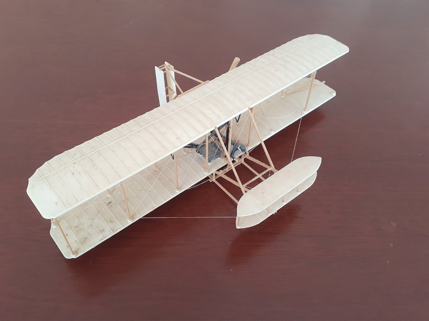
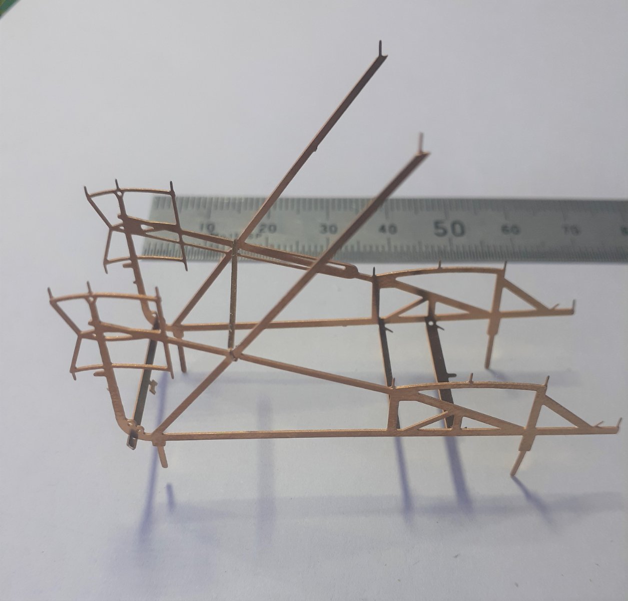
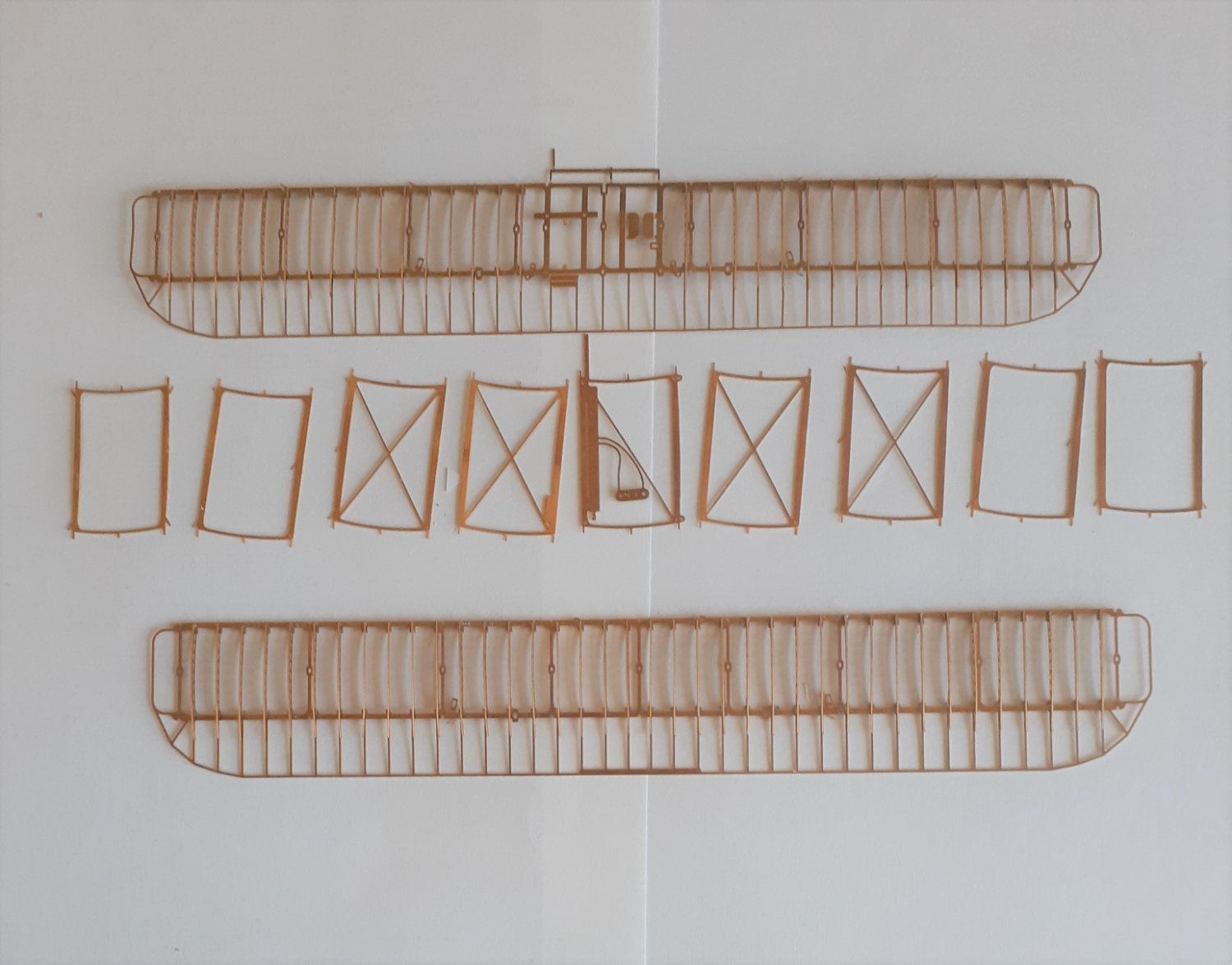
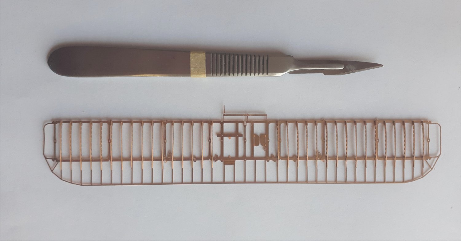
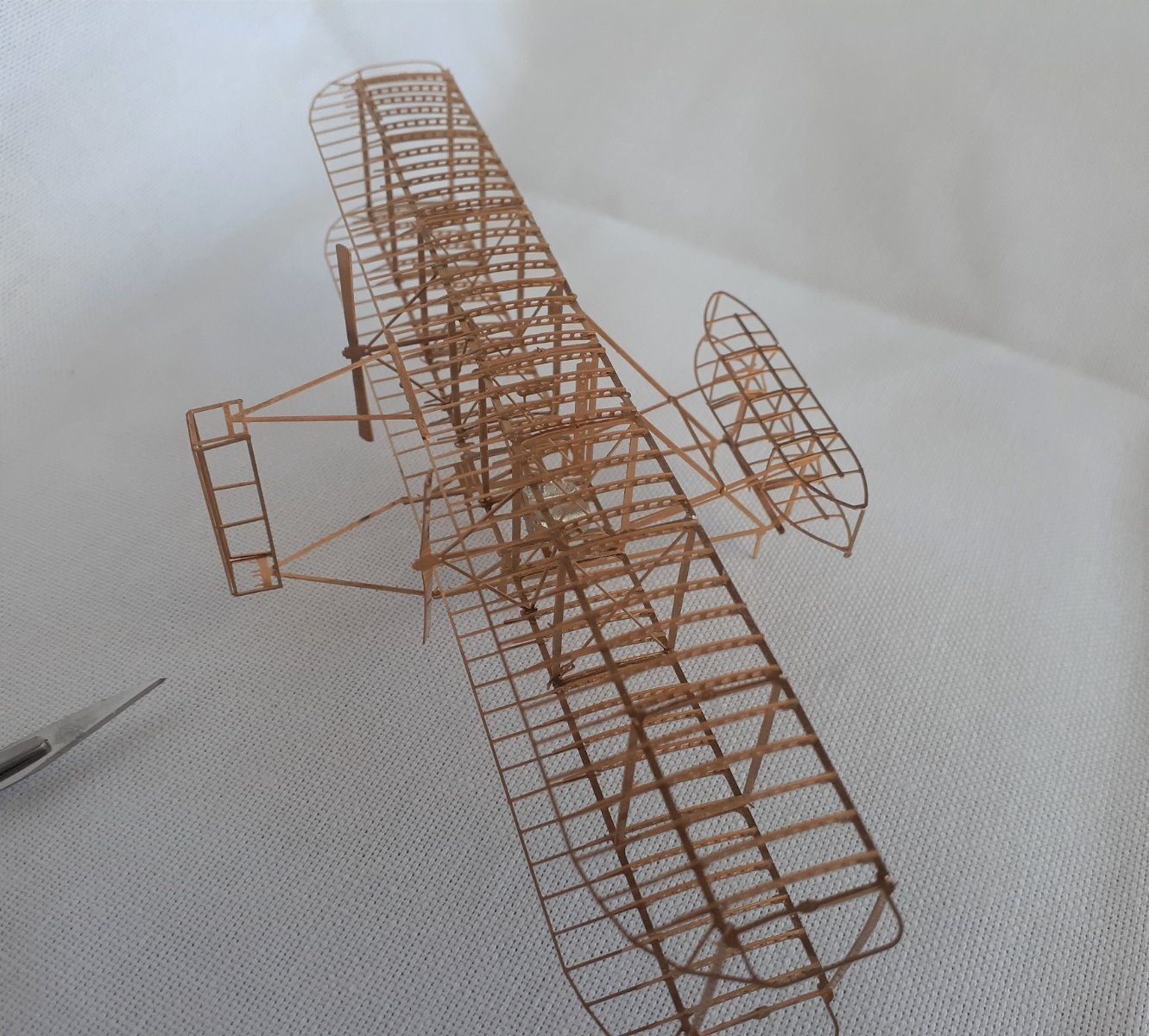
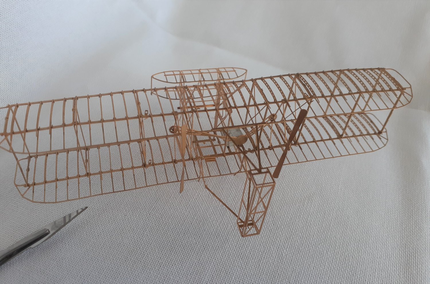
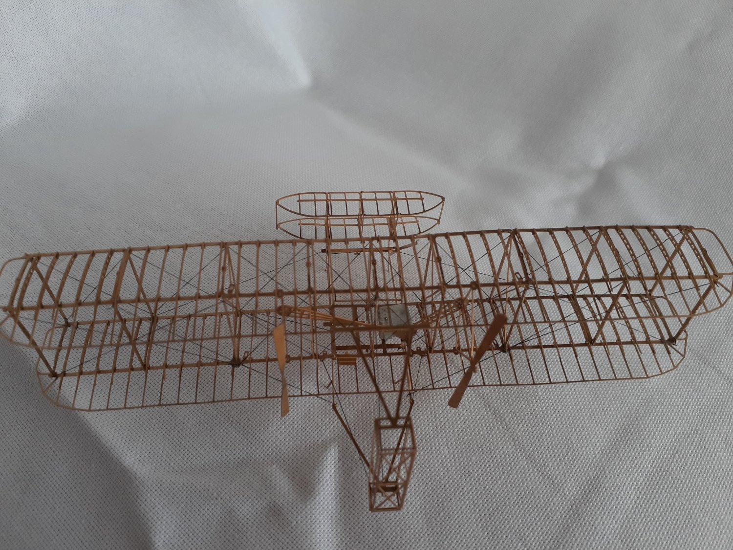
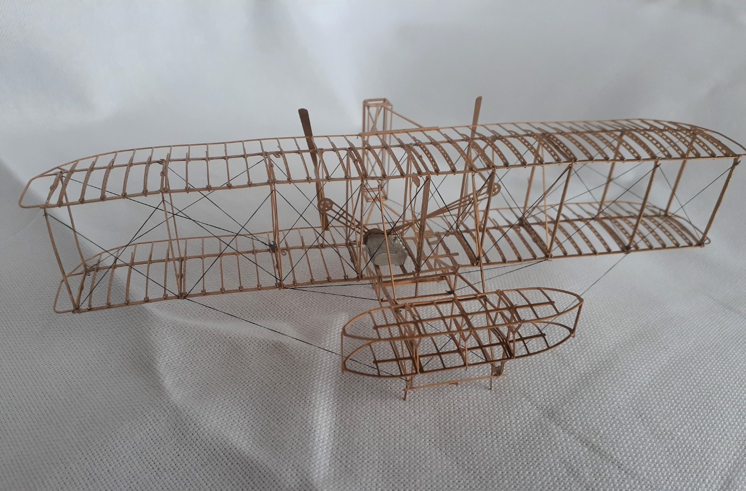
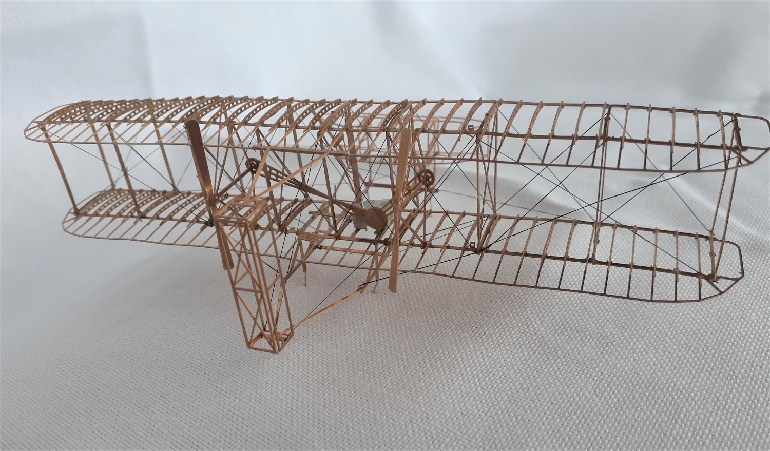
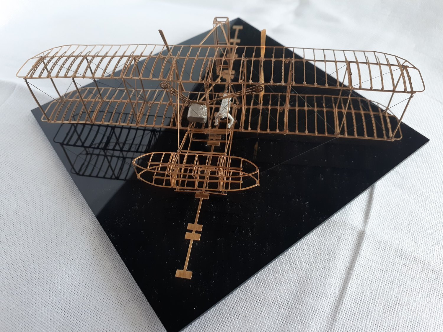
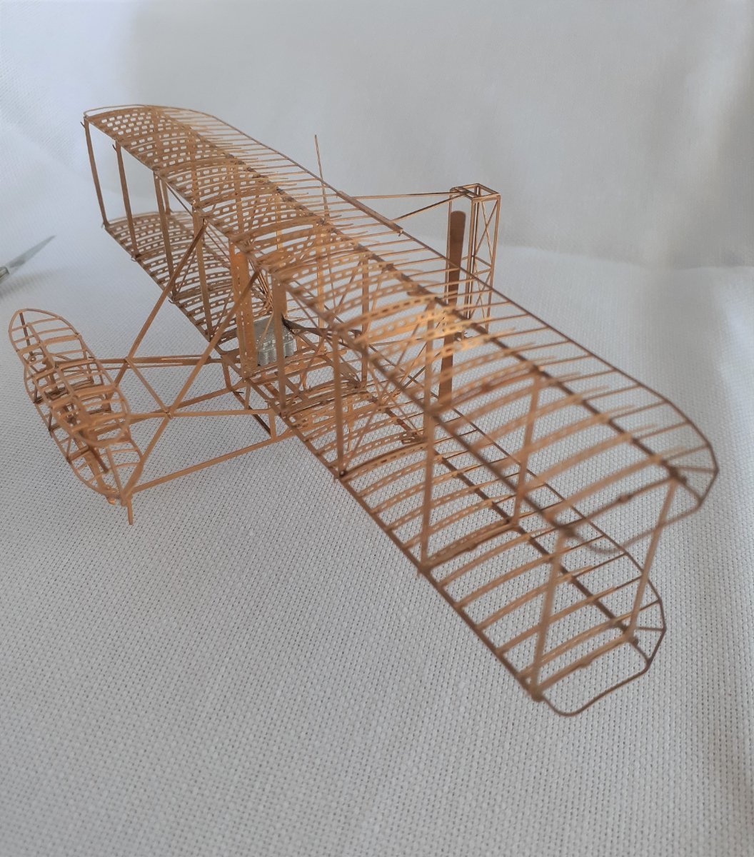
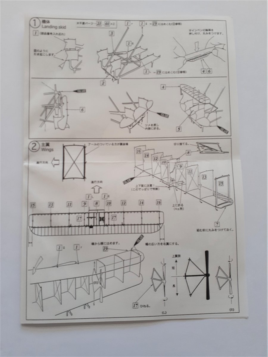
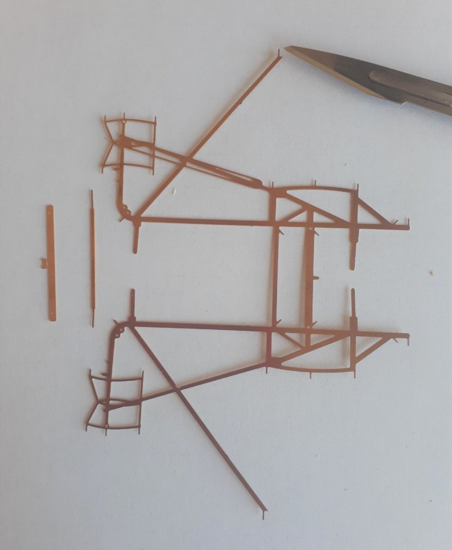
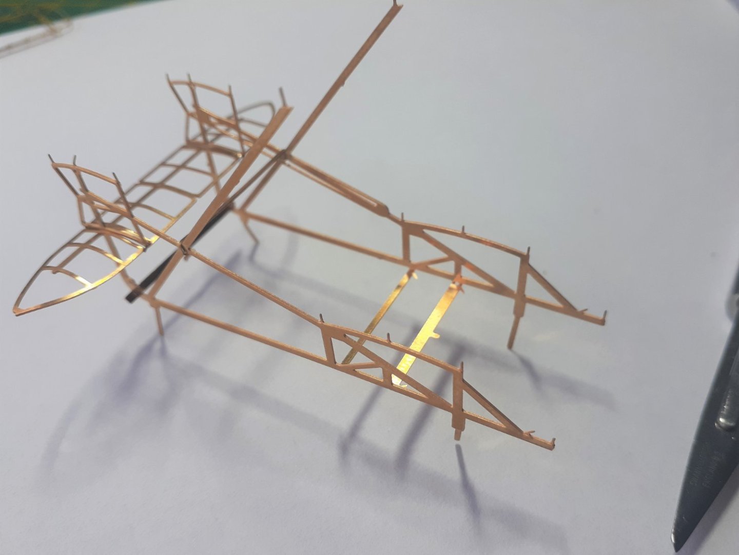
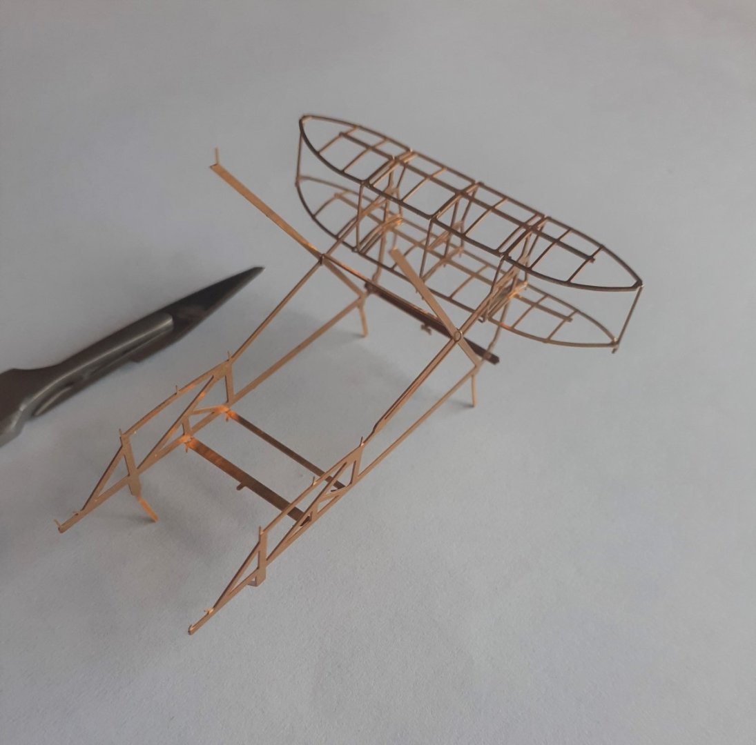
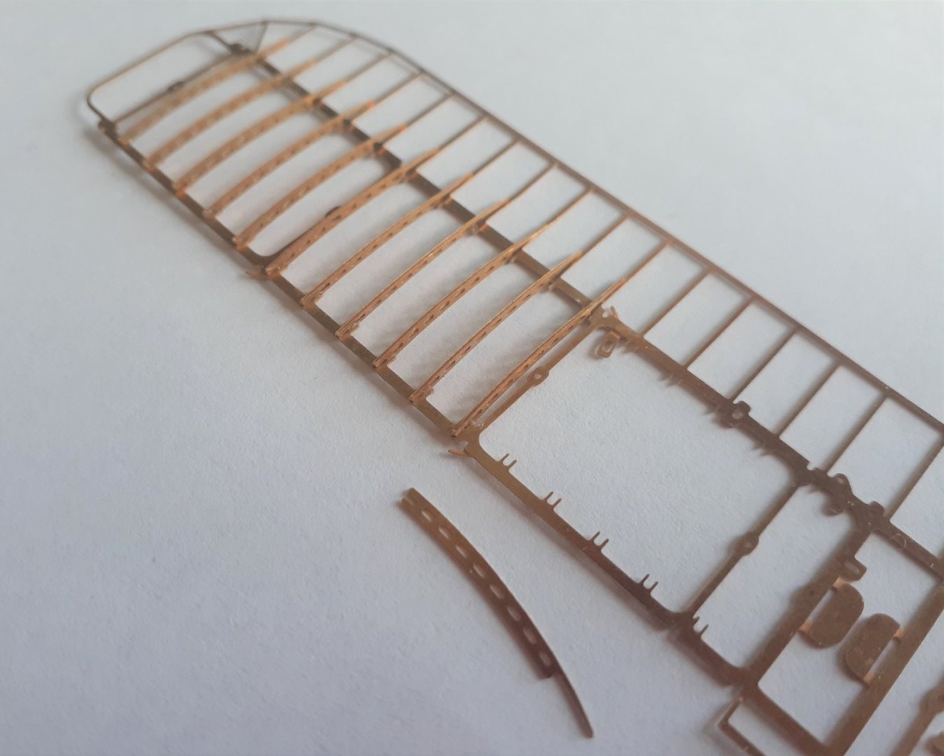
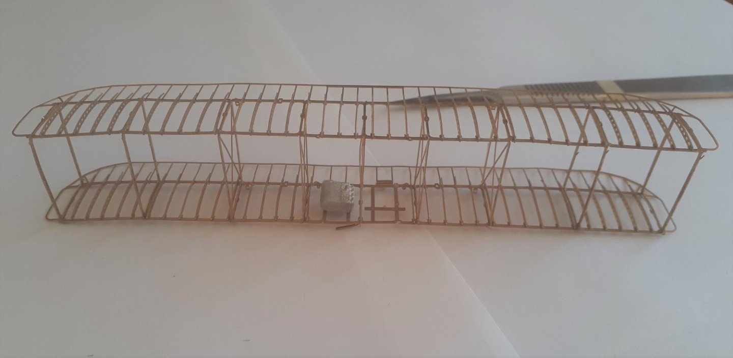
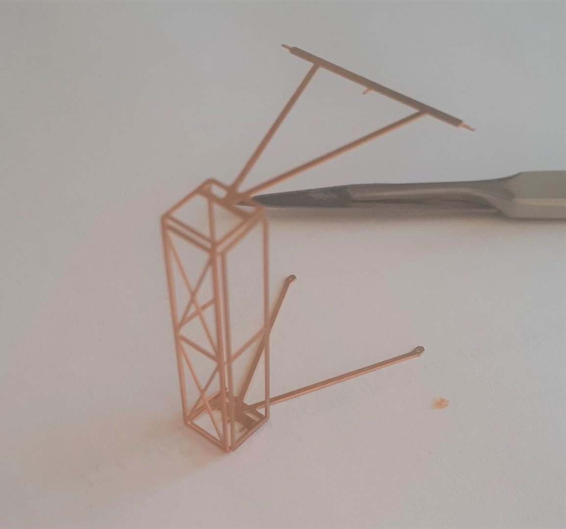
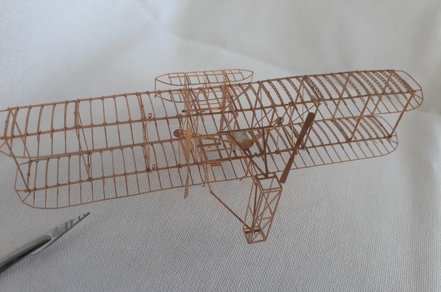
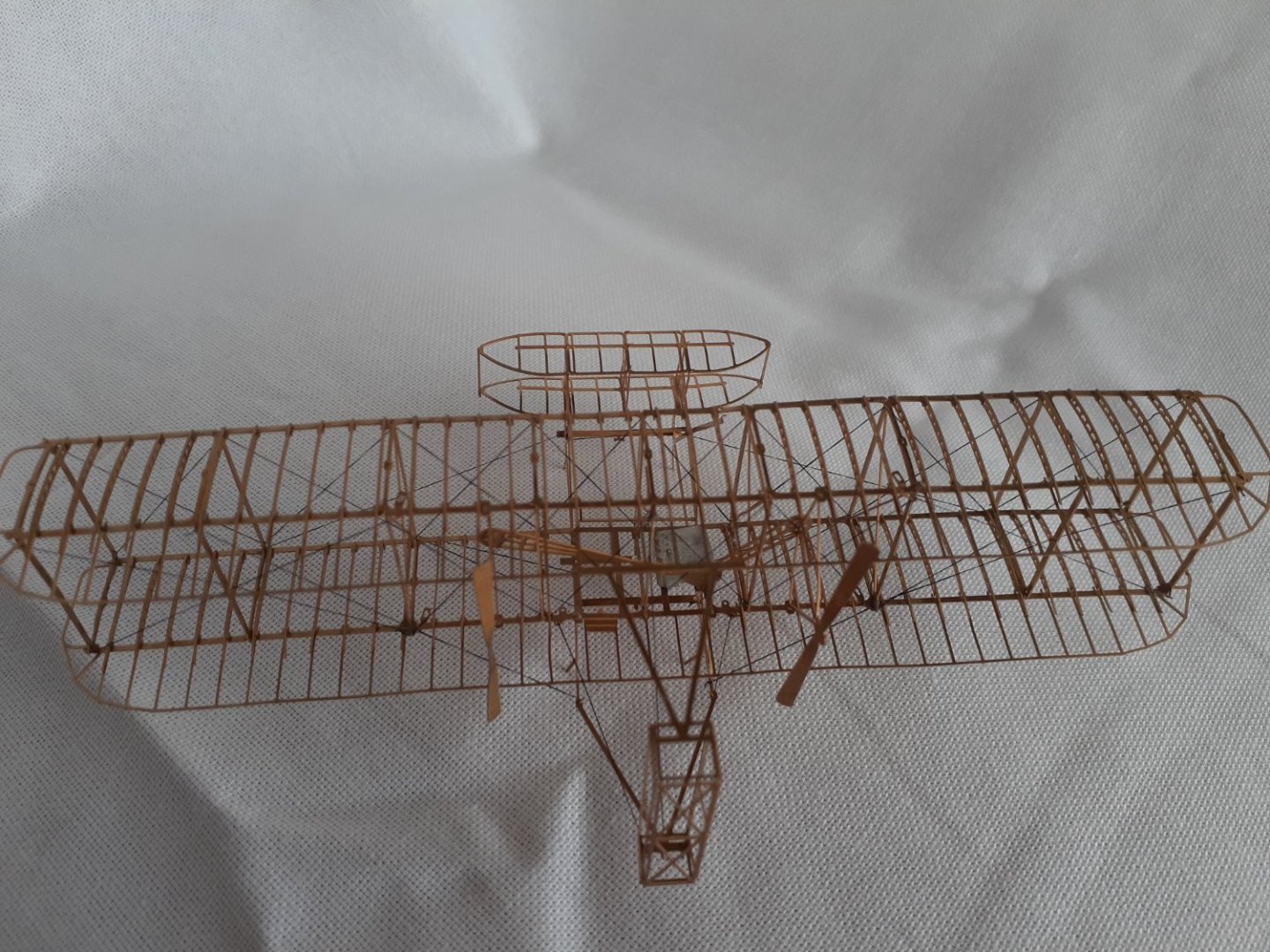
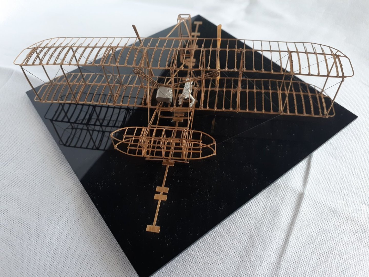
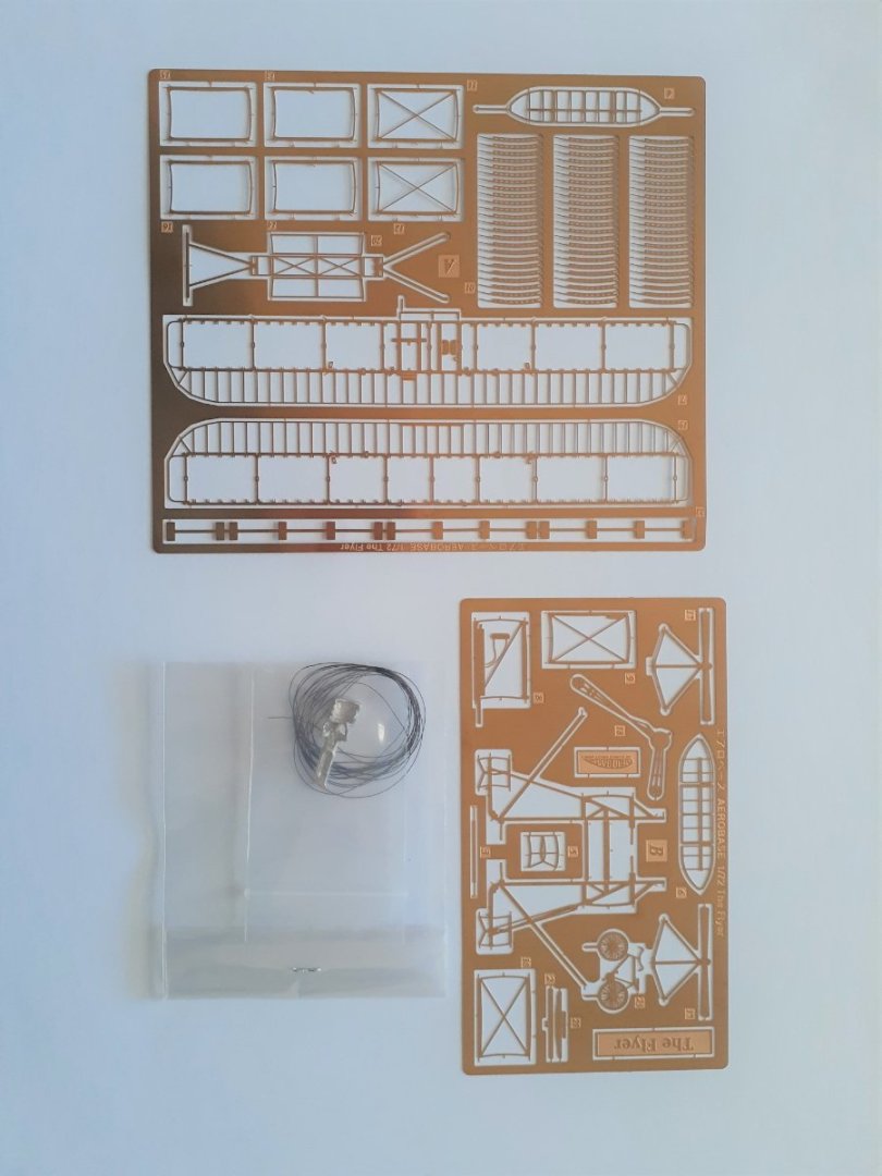
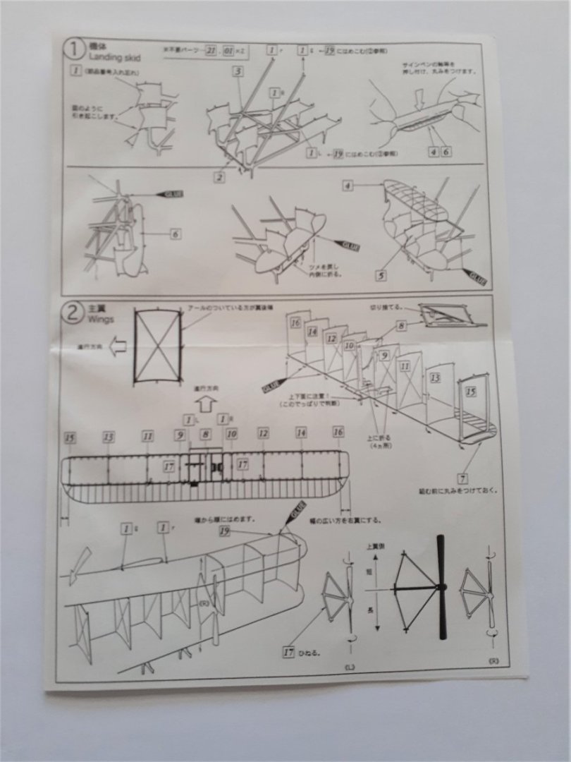
Many, many years ago I was an avid builder of plastic aircraft kits. One of them was the Monogram model of the Wright Brothers Flyer (scale was about 1:40). This didn’t survive a house move so I made a second. This too did not survive, so number three was built, and I still have it. Slightly the worse after a couple of house moves. I was idly browsing the net when I saw an ad for a 1:72 brass model of the Flyer, so I thought why not. The model is produced by a Japanese company called Aerobase (aerobase.jp), and comes in a stout box with two sheets of PE, three A4 pages of diagrams and a black acrylic display base. A cast (?resin) engine and figure representing Orville are included. The diagrams are annotated with instructions, unfortunately these are in Japanese, though they seem to be adequate - but we’ll see. The model is interesting in that most of the pieces are attached to each other with tiny tags, with the diagrams showing glue being used only occasionally. There are only 21 pieces plus the ribs, so this will not be a long build log. The first step is to form the forward framework that holds the two elevators. This framework is in one piece and only needs simple bending to form the correct shape. Visible in the photo are the tags used to attach parts to each other (one next to the point of the knife blade), these are vertical (in the photo) here, while other tags, at angles, will be used when rigging the plane. The framework with the lower elevator in place. Both elevators in place. The ribs for the wing are to be fitted into tiny slots, and the diagram shows that these slots then need to be squeezed tight. I tried this but didn’t have suitable pliers so I used drops of gel CA instead. The lower wing partly complete with a rib ready to be fixed. The lower wing complete. Both wings complete with the interplane struts ready to be glued in place. The struts have locating pins top and bottom which make assembly relatively easy. The two wings assembled together, with some “authentic” wing warping visible in places. I tried to remove the warping, but there was a limit as to how much pressure I was willing to apply to the wing. The rudders that needed only a few bends to be formed. The assembled plane, though without rigging. The plane rigged, but no pilot yet. The kit came with some normal thread for the rigging, but I chose to use one of the fine, elastic-type threads, not EZ-Line but something similar (AK Thin). Rigging was a real exercise in patience. There was not a lot of room to get thread, tweezers and fingers in simultaneously. Several breaks were required to allow stress levels to drop. Mounted on the display base. Some of the diagrams weren’t as clear as they could have been, and the order of assembly appeared to be decidedly odd with the ribs apparently being added (Step 5) after the plane was assembled (Steps 2,3,4). Not what I did, as this would have been near impossible. Anyway, a neat little model. Cheers


- 14 replies
-
- 17
-
-
-
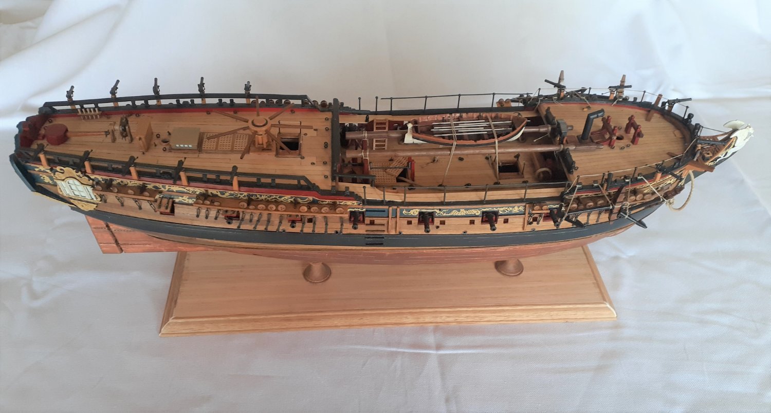
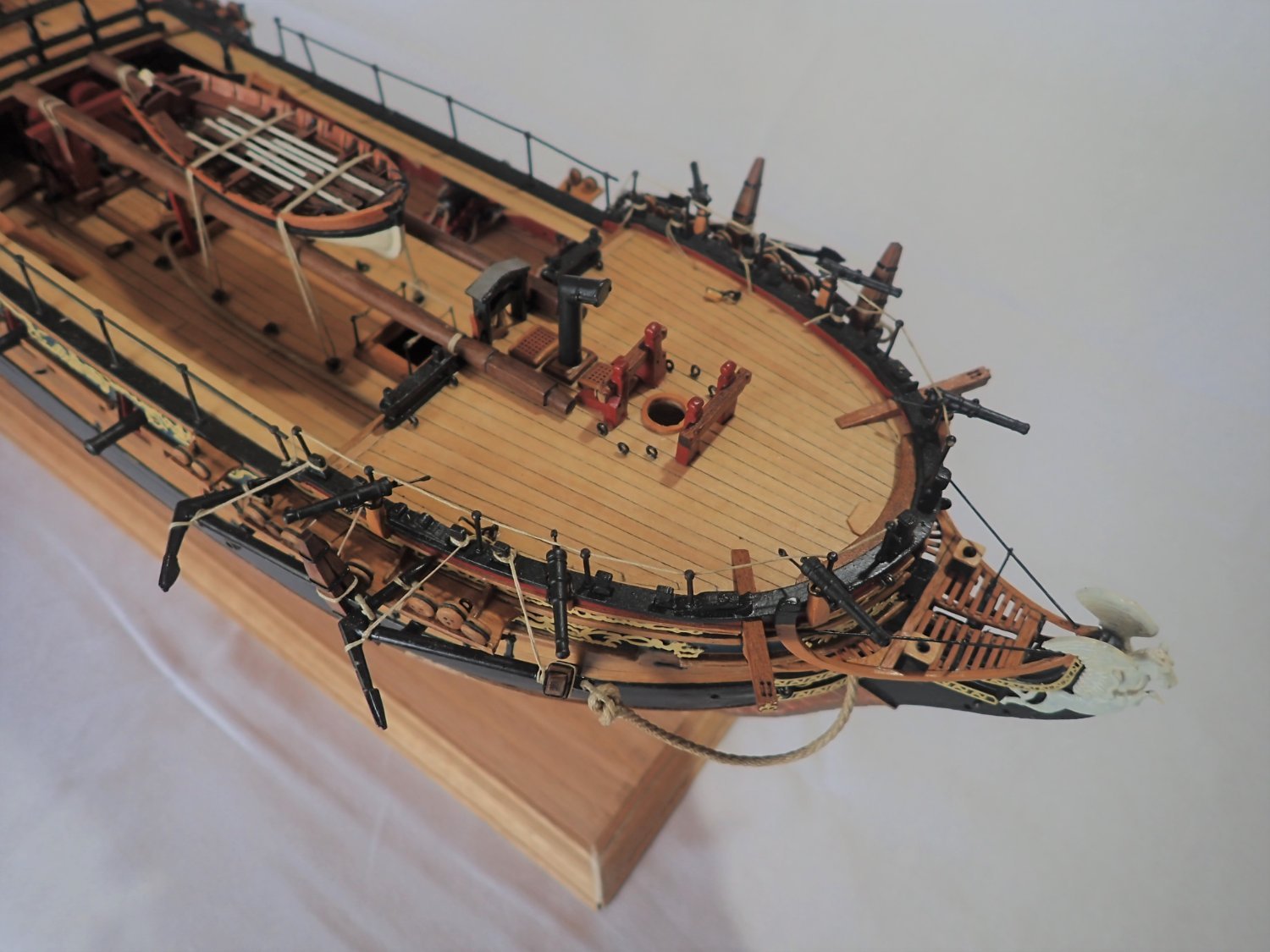
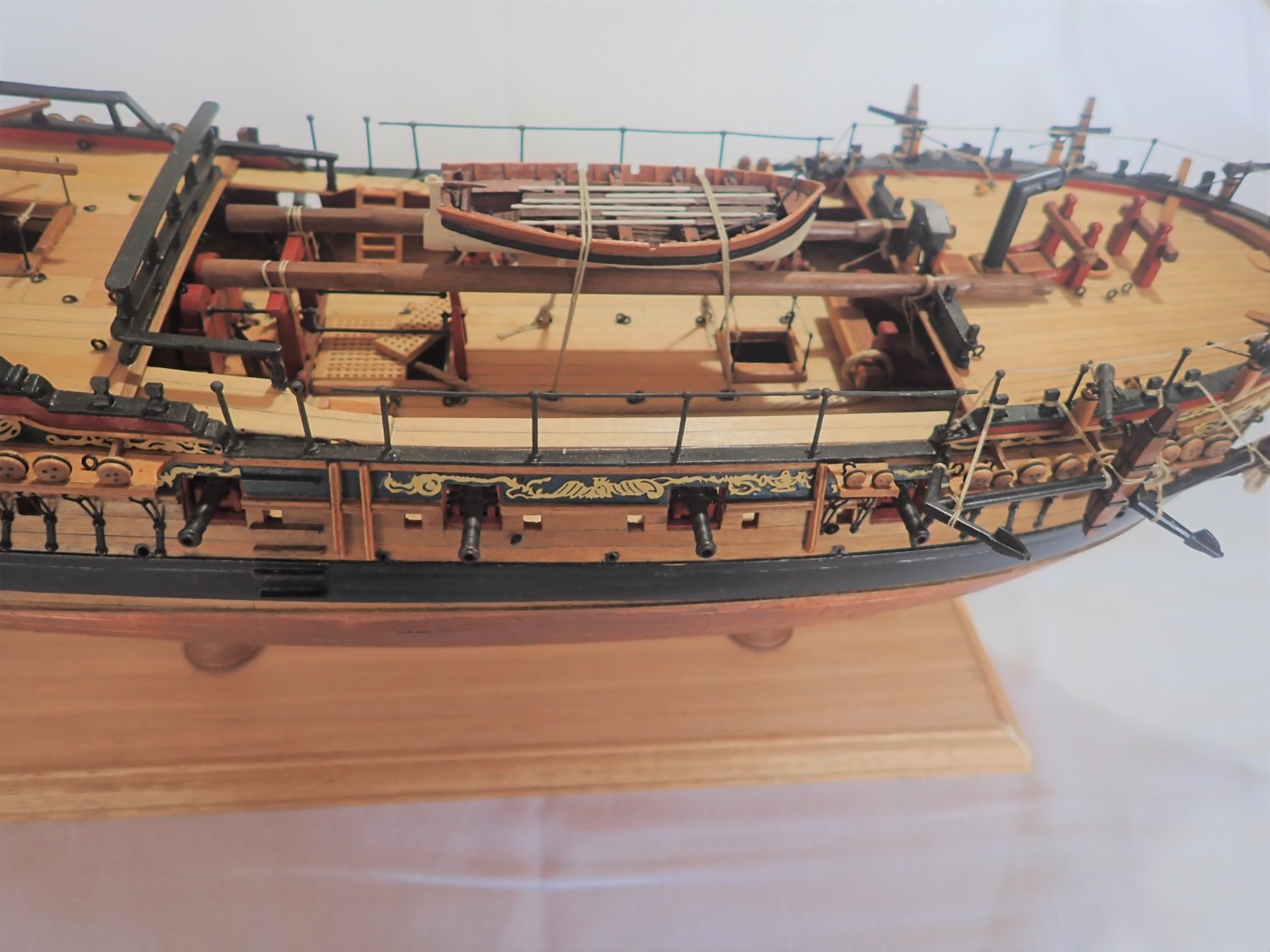
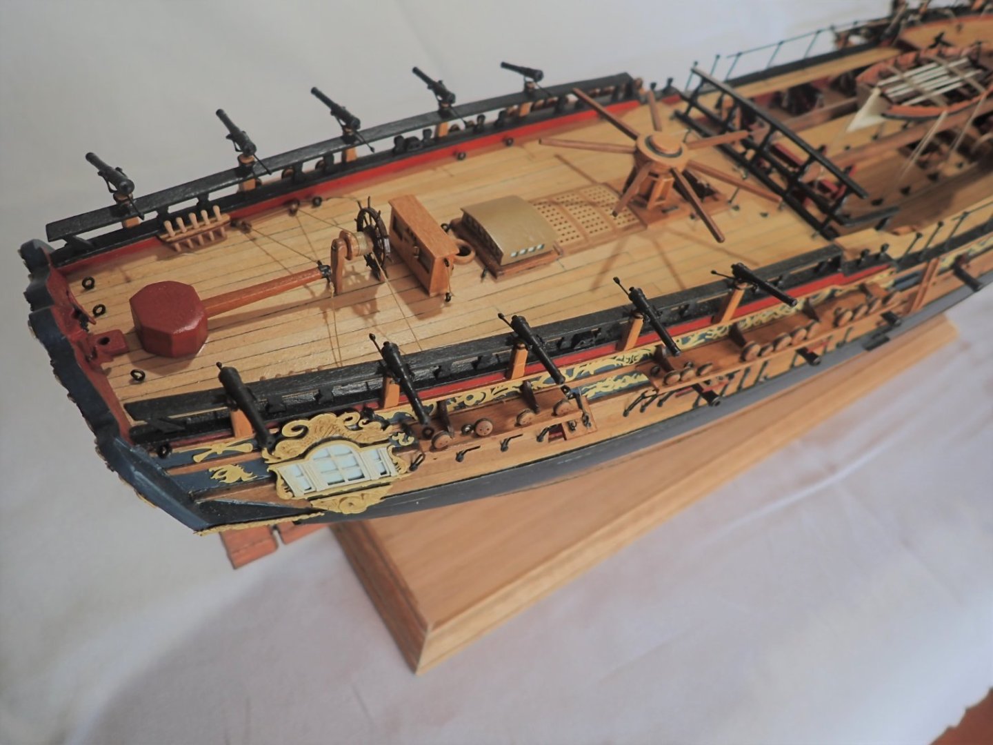
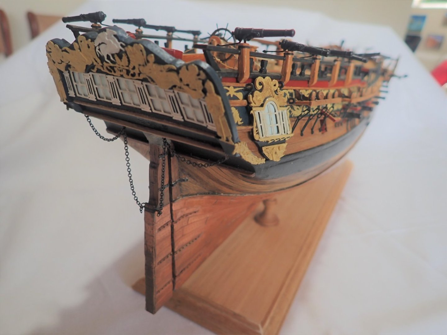
Ok, so Pegasus has been sitting idle for some months now. I have finally decided that I am not going to go with the masting and rigging, so here are a few final photos, and I declare Pegasus to be finished. It’s been an enjoyable build but I don’t have the enthusiasm to take it further. So thanks to all those who added likes or offered comments and advice. Cheers


- 104 replies
-
- 12
-
-
- pegasus
- victory models
- (and 2 more)
-
Can't help on the absence of the banner, but they still seem to be in business as I ordered some stuff from them the other day and it's on its way.
- 1 reply
-
- 2
-
-
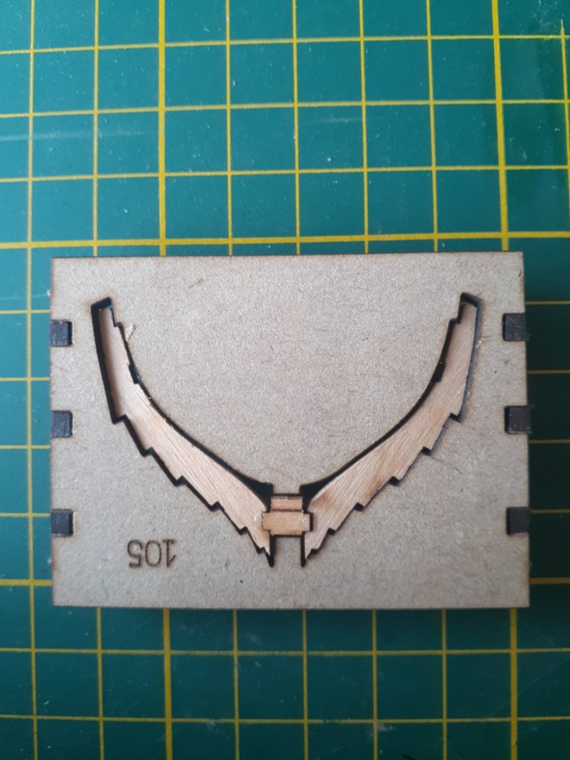
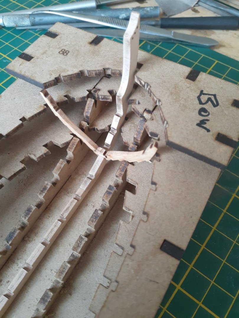
Hi Jerry, Yes, the frames have to go in face down. If you look at Olha's video, about 14:30 in, you can clearly see her putting frame 22 into the jig 105 face down. What initially confused me is that you can see a laser-etched line on the back of the frame sides. Olha must have a slightly different kit to me, and probably you, as mine does not have any etched lines on the back of sheet 1P (the sheet with all the frames etc). A close look at the diagram for frame 22 on page 12 does show the position of the etched line that we don't have. I glued up frame 22 this morning and two photos of it are attached. The third photo is of the frame loosely in position on the keel. Cheers

-
"Olha" is Ukrainian, "Olga" is English. Her English language website identifies her as Olga. Whatever 😊. Her modelling skills are far better than mine😁. I'm following your log with interest Jerry, as I have the model as well, though I haven't started it yet. Cheers
-
Hi Jerry, Have a look at Olga's video, about 14:50 along - she shows the frame you are having problems with. I hope the link works. If it doesn't find the video via James' post on the shallop. Cheers
-
This is really for the Aussies amongst us. I over ordered some Syren brown rigging cords and no longer want/need them. Free to locals but a donation to MSW would be appropriate. The cords are all brown, 0.008x3, 0.025x2, 0.035x4, 0.045x2, 0.054x1 and 0.12x4. PM me. Cheers
-
- 2
-
-
48th Scale imperial rulers. Where?
Richard44 replied to John Murray's topic in Modeling tools and Workshop Equipment
Hi John, I too am in Aus and I happen to have a 12 inch three-sided Imperial rule that includes 1:48. I no longer need this so if you pm me your address I'll send it to you. Cheers -
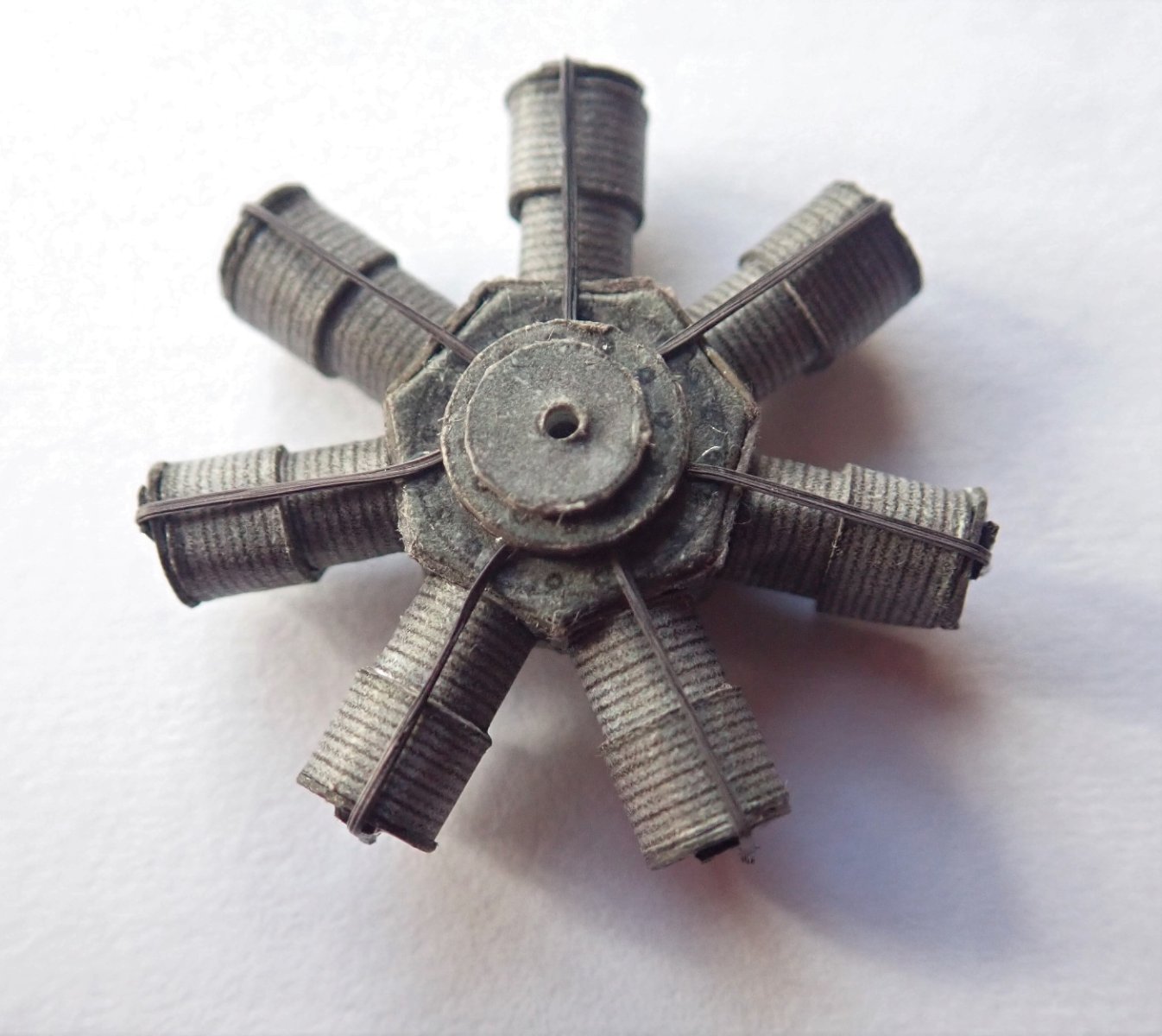
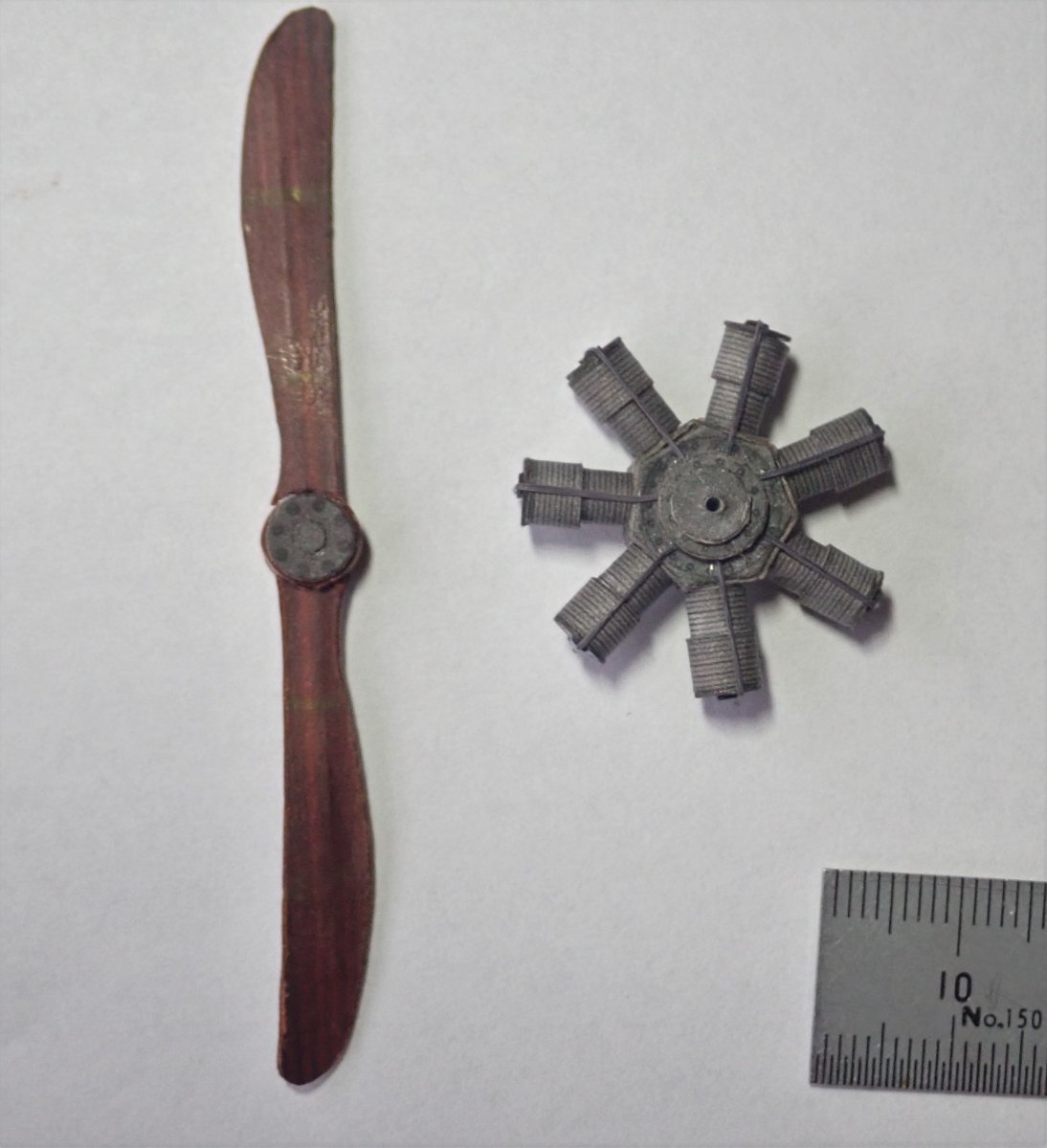
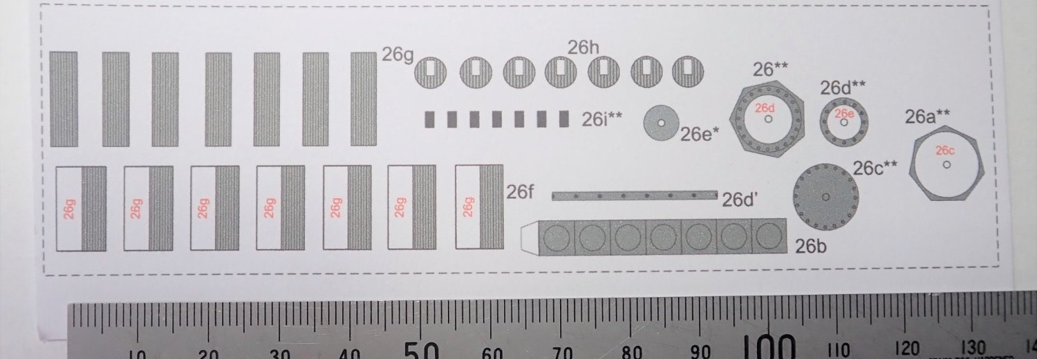
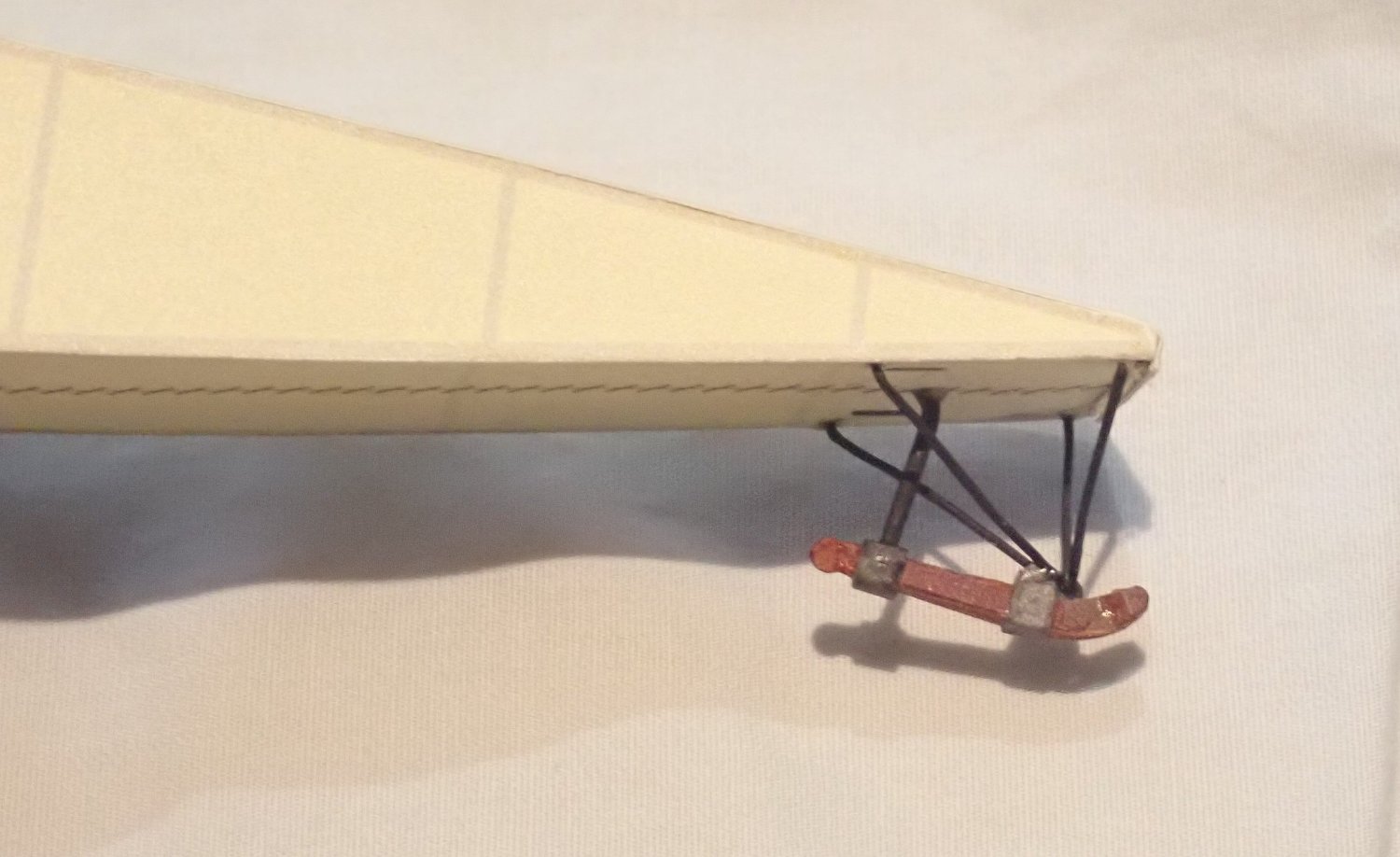
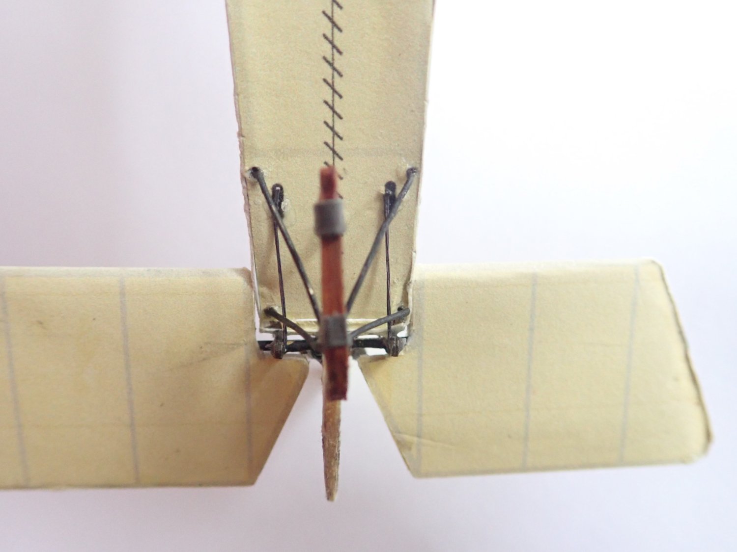
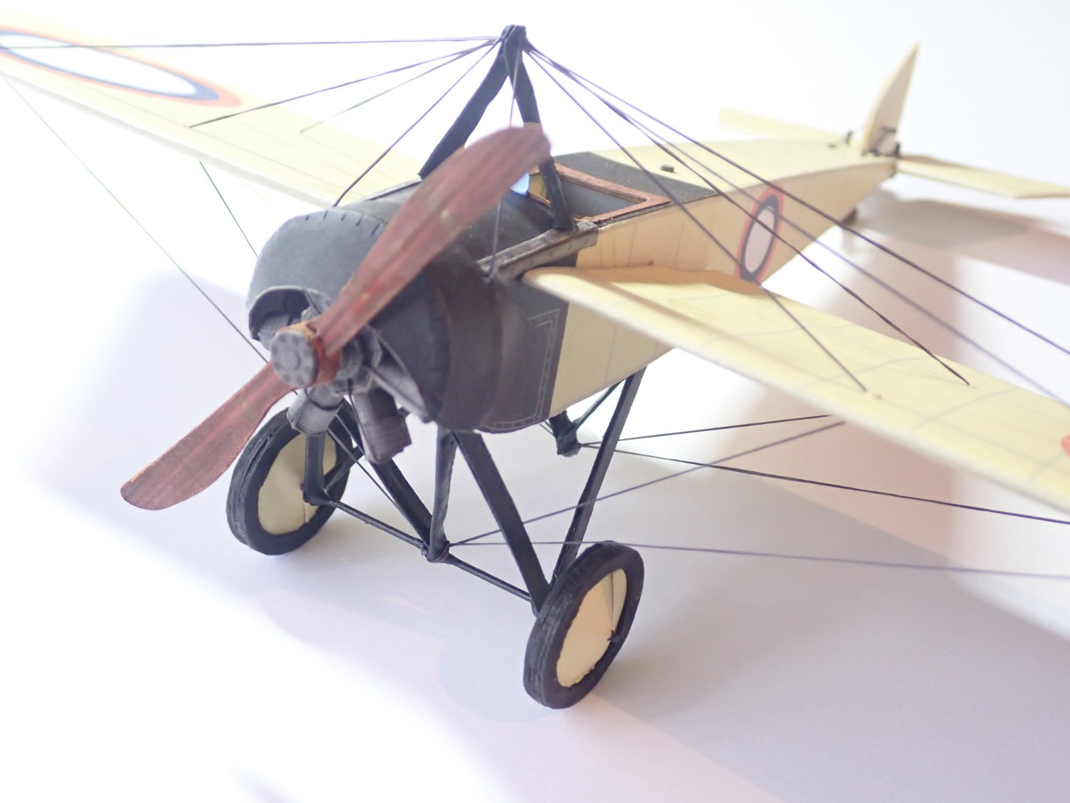
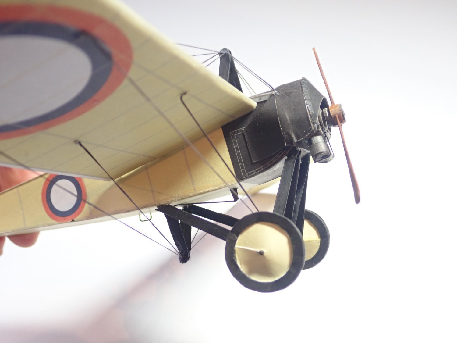
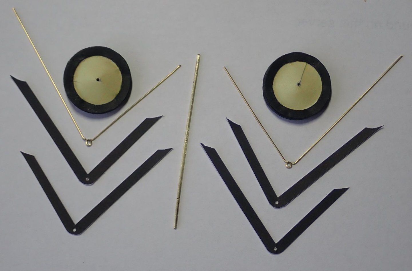
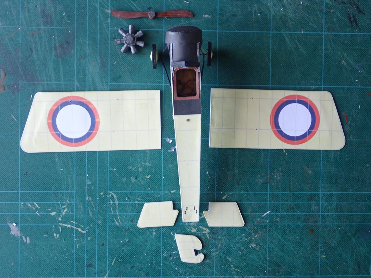
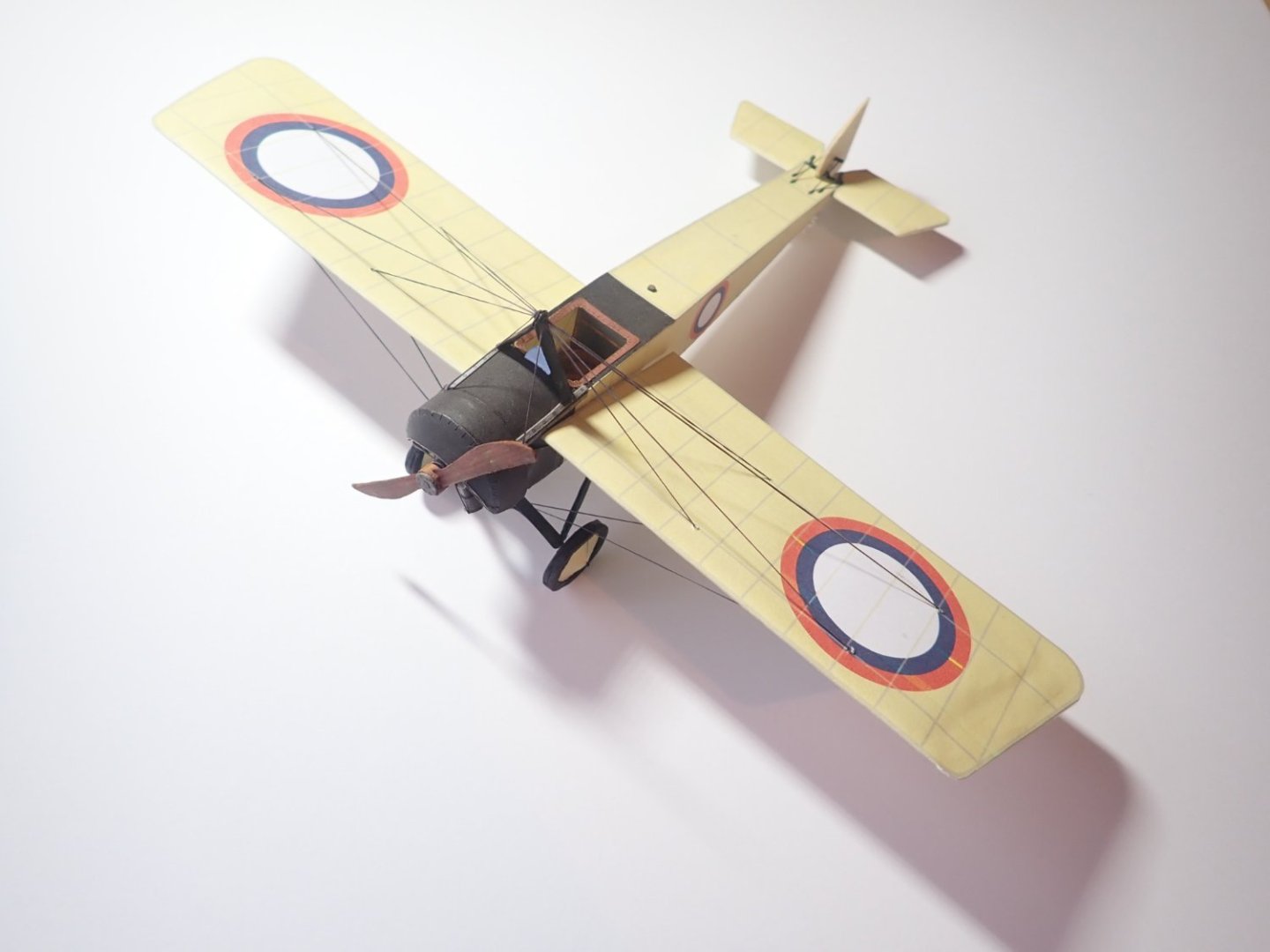
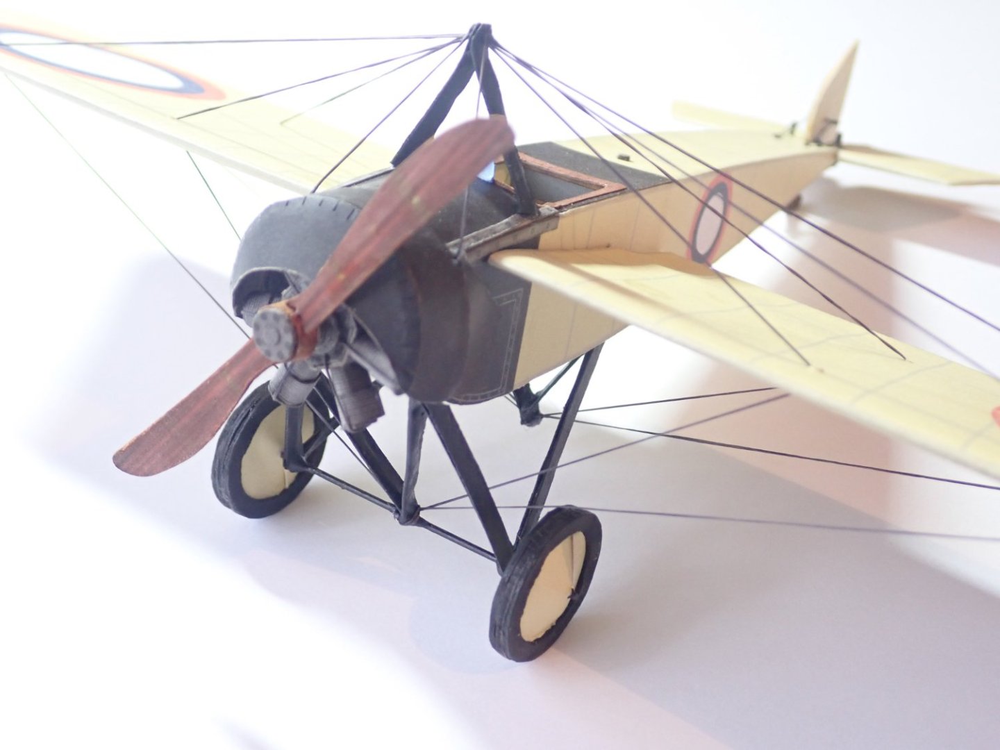
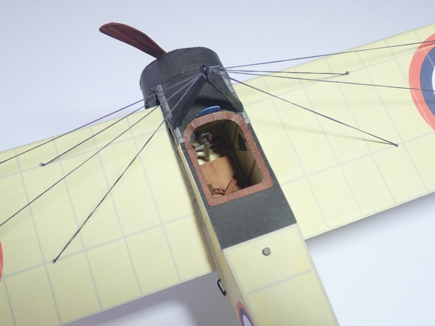
Thanks for the comment Ken, and for all the likes. There were 35 parts for the 7 cylinder rotary engine, plus another 10 parts for the propeller. The blades of the propeller are stiffened with short lengths of 1mm brass rod (and I should add here that there are templates provided for all the wire/rod parts). An interesting exercise in assembling the engine, and the diagrams had to be studied carefully in order to do this correctly. The engine parts, the completed engine and the engine plus propeller. The tail skid is made up of a bracket and leg that support the card skid itself. The leg is 1mm rod, while the bracket has two parts of 0.5mm rod which I silver soldered together. This was my first attempt at silver soldering, and after attempts two, three…I finally managed to achieve an acceptable result. The undercarriage is typical, two V-shaped struts plus axle. There are an additional three V-shaped struts through which the cables that controlled the wing warping run. One goes from the undercarriage to the bottom of the fuselage, the second downwards from the bottom of the fuselage at a point level with the rear of the undercarriage, while the third is on top of the fuselage immediately in front of the cockpit. All of these struts have a rod core with a card skin. I need more practice in doing struts such as this as my attempts are not as neat as I'd have liked. There was a choice of how to build the wings. Either cut out 22 individual ribs, assemble with a “spar” then add the skin, or laminate a core then skin it. I went for the latter, easier method. The photo shows the four parts that are to be laminated plus the two 1mm diameter wire spars, one of which passes right through the fuselage. The tail surfaces are simple card cores that are skinned. The elevators have a rod joiner and there is a rod at the leading edge of the rudder (there is no tailplane or fin as such - the surfaces are all-moving). The main components of the aircraft ready for assembly. When the engine was slotted into the cowl, it was apparent that the propeller could not be attached to the engine without a spacer between the two being added. There was no way that the engine could be moved forward or the propeller moved back - the cowl was in the way. So a spacer was added. Attaching the wing to the fuselage was easy enough - the two wire spars ensured accurate location. The tail surfaces though were difficult. Both the elevators and the rudder need to be fixed to the very end of the fuselage, a gluing surface of about 10x2mm. There is also the problem of the horizontal rod of the elevators and the vertical rod of the rudder both being attached, to the fuselage and effectively to each other, by very small pieces of card representing the hinges. If I’d thought about it much earlier, I probably would have attempted to silver solder the rods together and then make the elevators and rudder, thus making the rear surfaces a single unit. I had to use epoxy and fake the hinges. The fuselage rear from underneath. The control horns were added. All rigging was done with heavy EZ-Line. It is noticeable in places that the line is twisted as it is not round in cross-section but rectangular. I saw this too late to fix while rigging and decided that trying to correct it later was likely to cause damage. The finished aircraft. Quite a nice little model. Not too difficult to build. My apologies for the brevity of the log. I sort of got tied up with the building and forgot to make notes or take photos. Cheers


-
Hi Edward, You've convinced me to actually do a build log of the WAK Morane-Saulnier G, a model I completed some weeks ago. The log is here. You're doing really well with your Sopwith. Cheers
- 93 replies
-
- 11
-
-

-
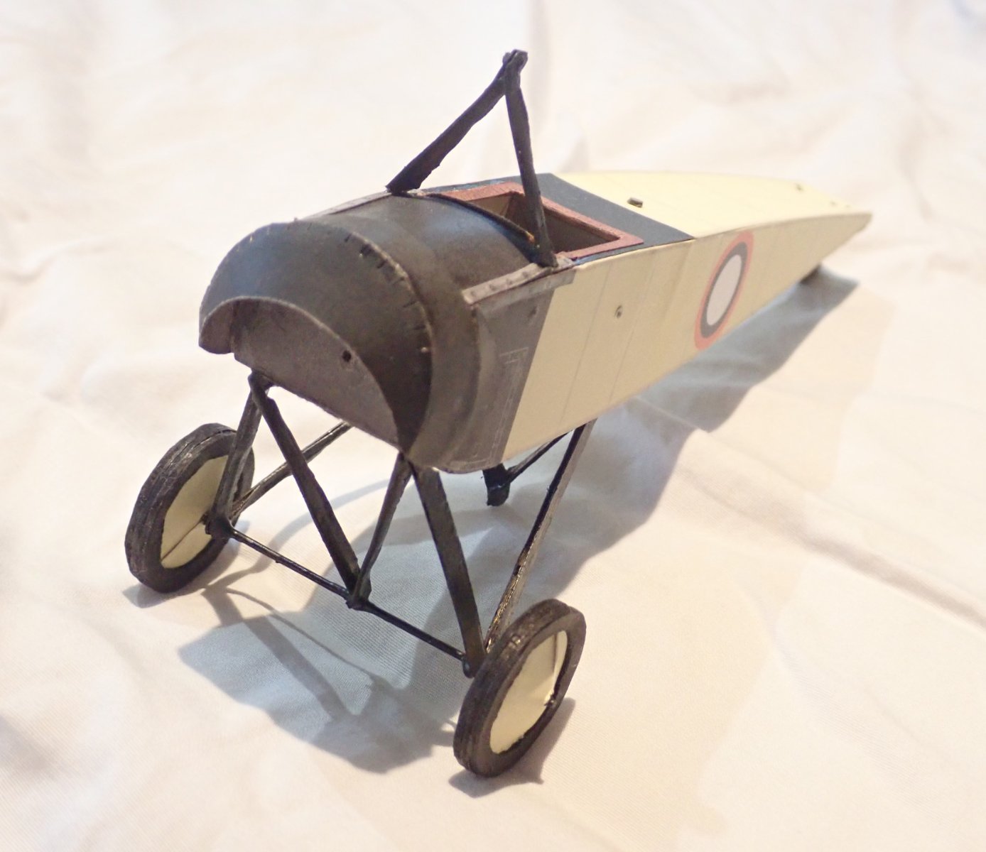
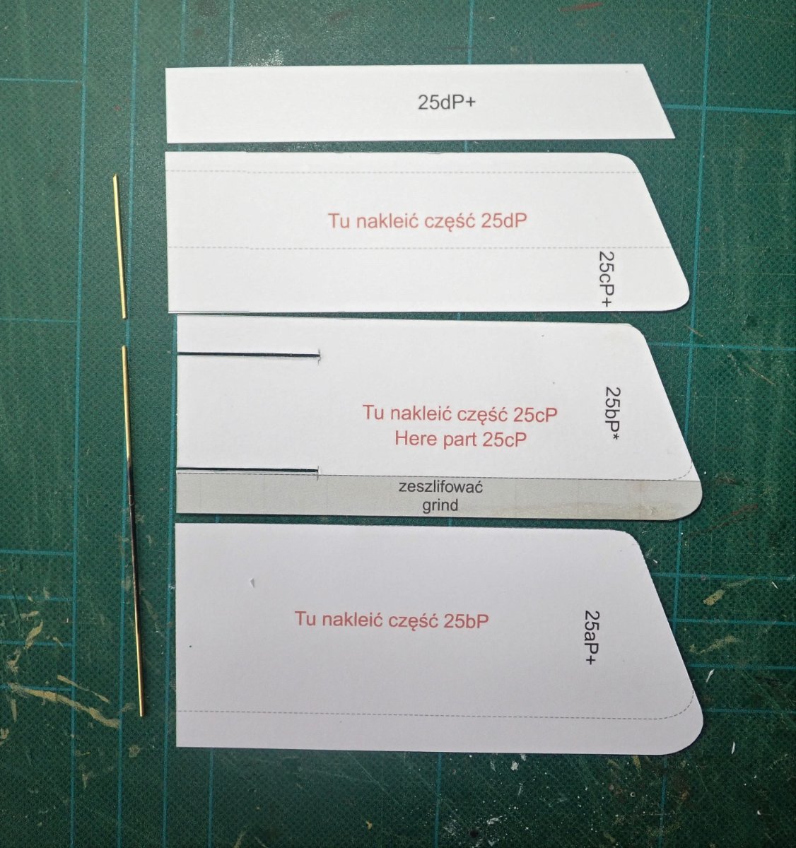
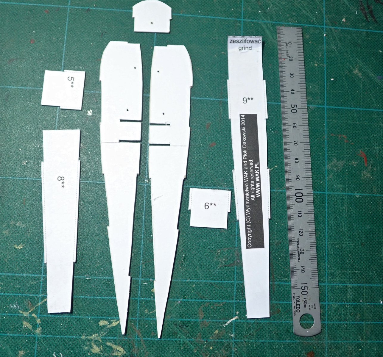
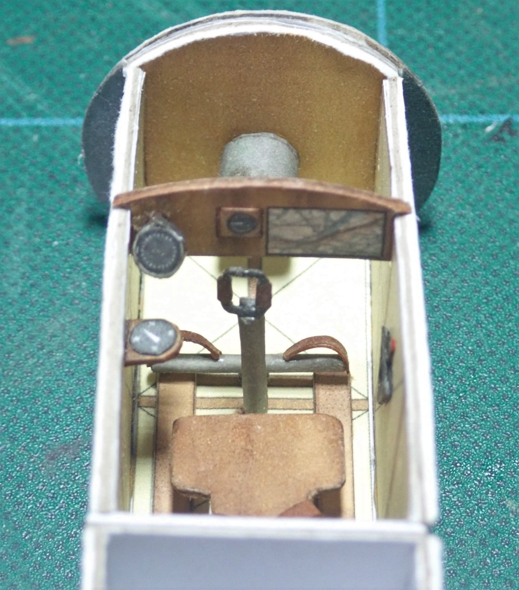
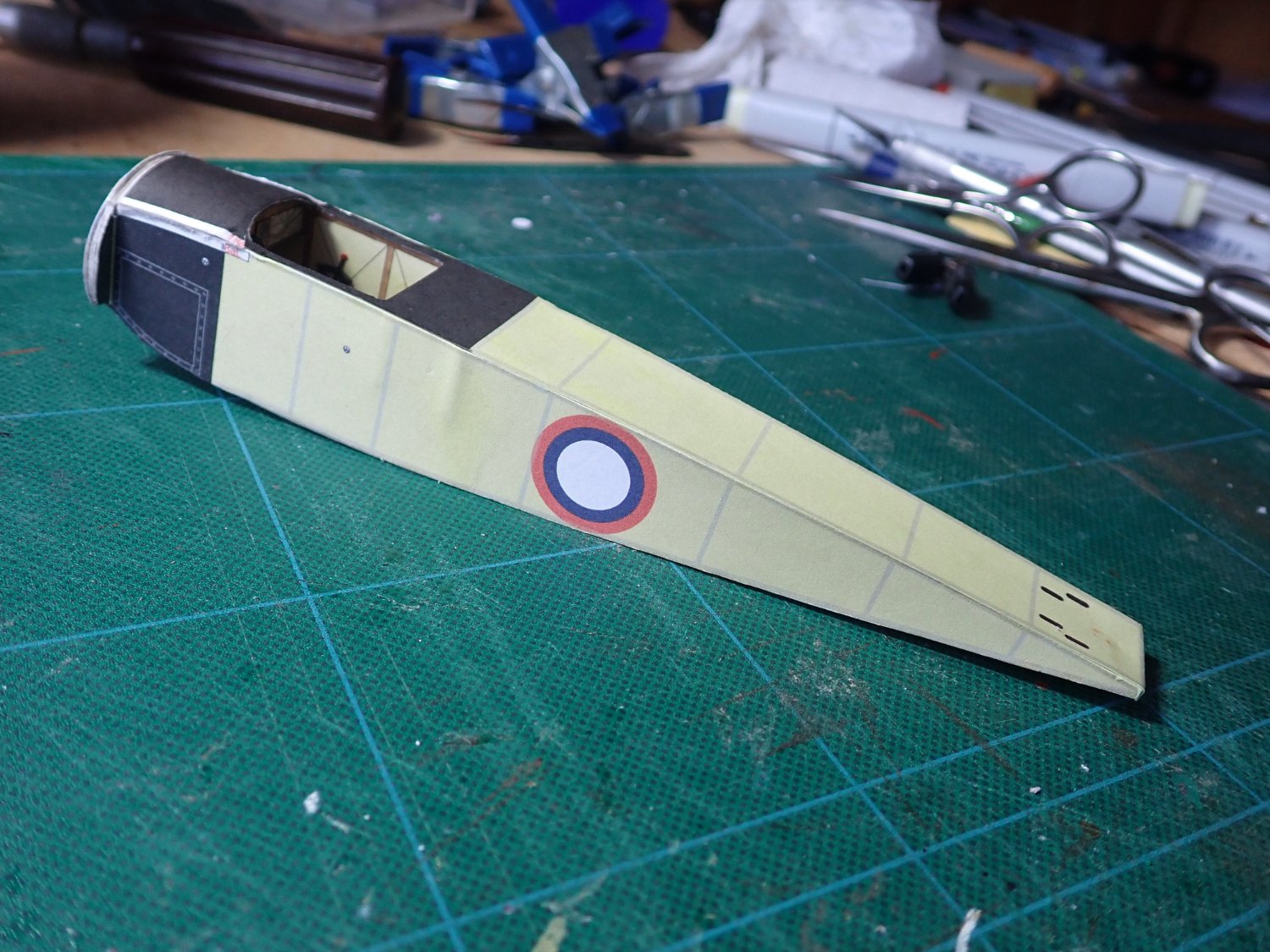
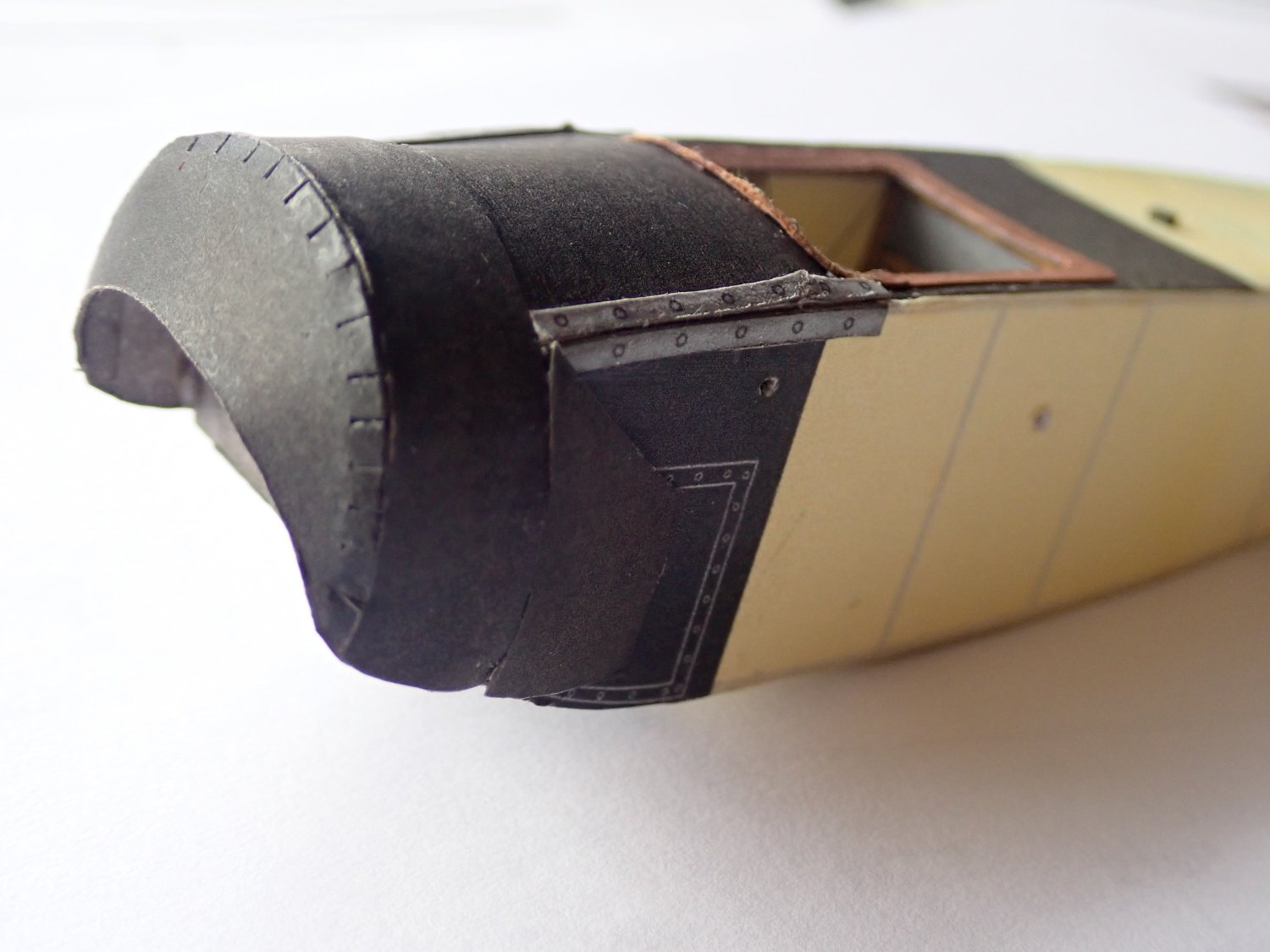
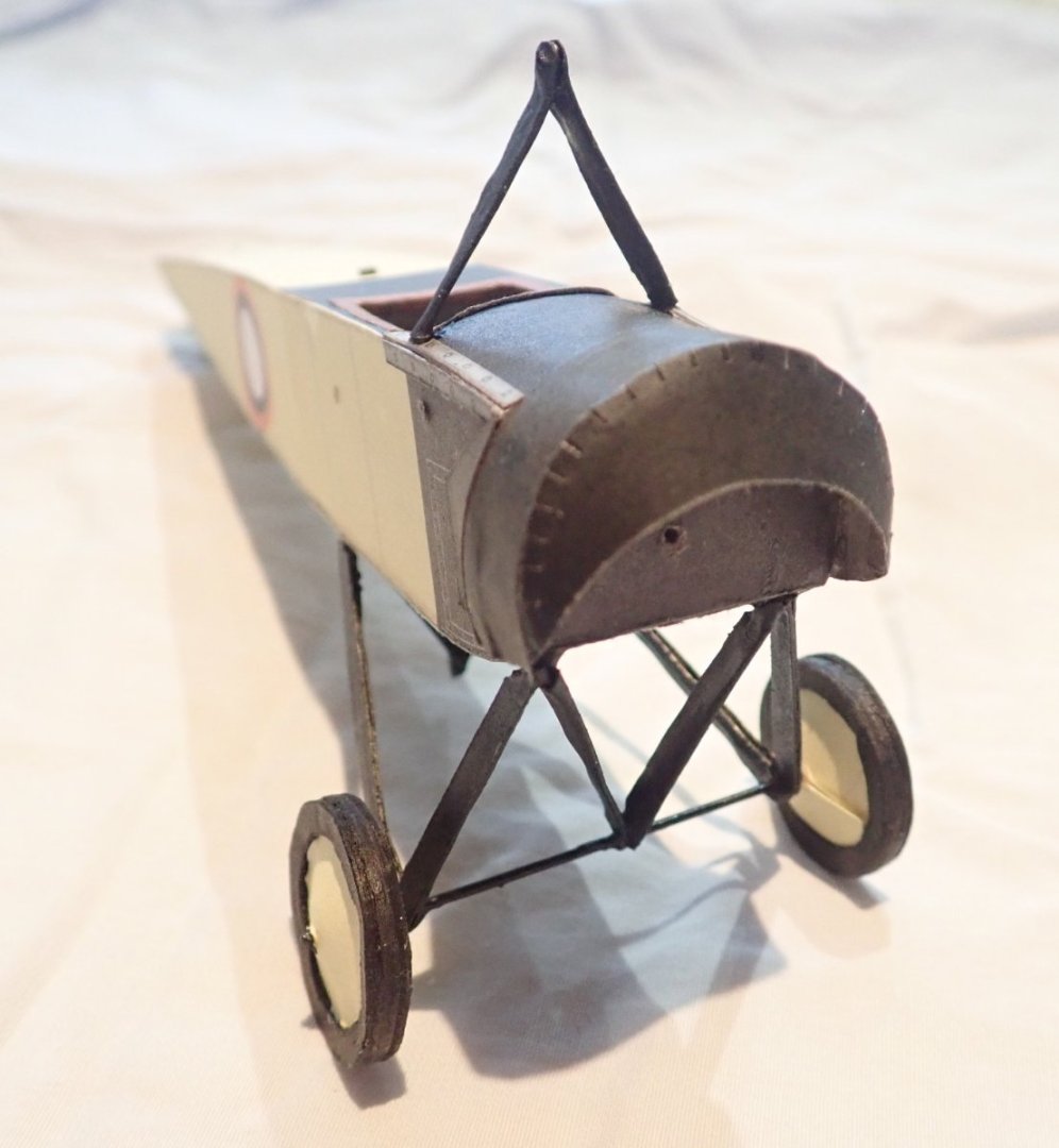
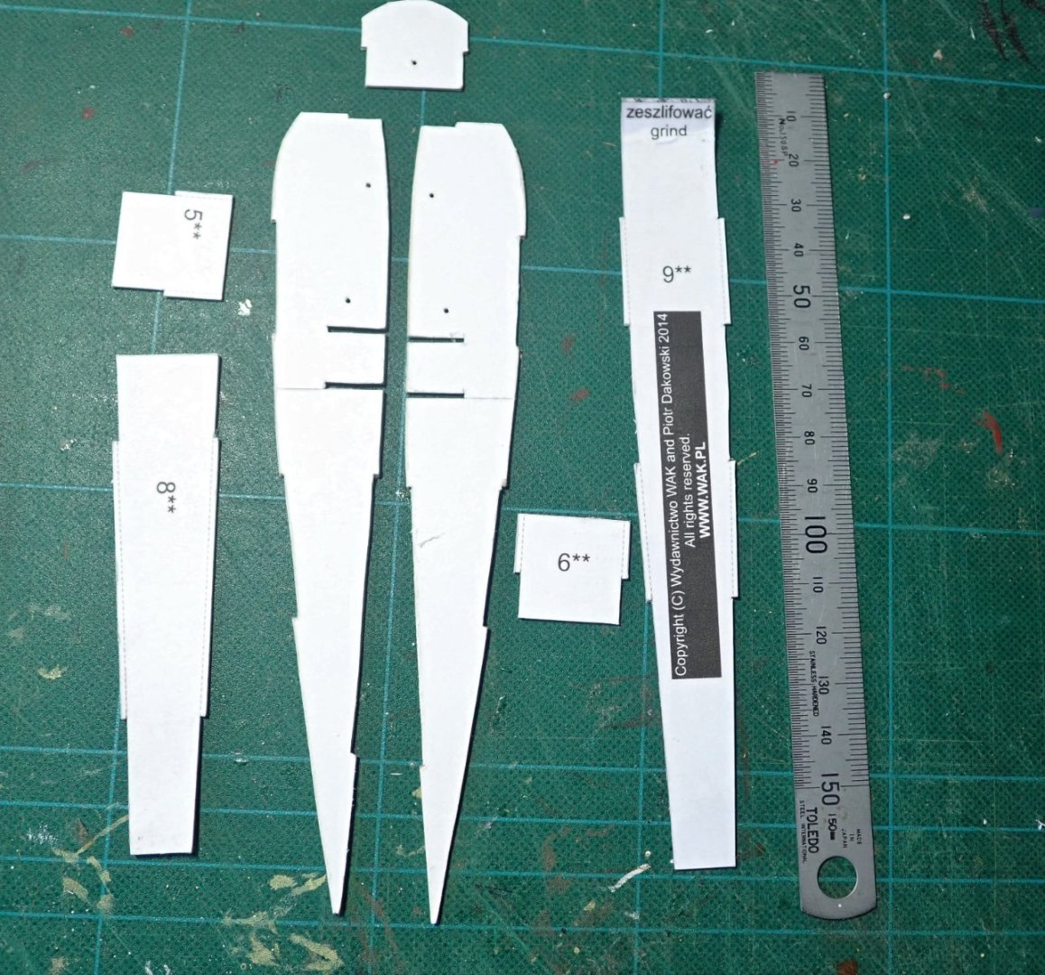
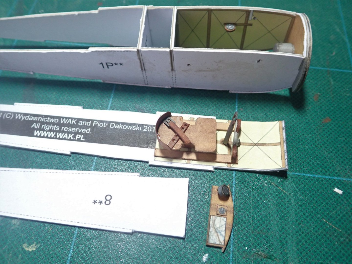
Ok, so Edward has caused me to get off my backside 😁, and add this build log of the Morane-Saulnier G monoplane that was built around 1912. A minor confession - I actually completed this model some weeks back, and the build was not as quick as this log might suggest. The plane is a free download from the WAK site. A Google search shows that the “G” model was actually a two seater, but this kit is for a single seater. So exactly which model the kit represents is a bit of a mystery. The kit depicts an aircraft in the service of the Russian Empire, and was probably used as a training aircraft as no armament was fitted. It would have been obsolete by the time WW1 broke out. Once printed, there are three sheets of parts and three sheets of diagrams, but the only instructions are those indicating which parts need to be laminated to thicker card.The contents of the kit. The basic parts of the fuselage that have been cut out after laminating onto 1mm thick card. The diagrams indicate that these should all be glued together as the next step. This would have made it difficult if not impossible to add the inner skins and details in the cockpit area. So the skins were added to the sides and floor, then the seat, joystick, rudder pedals etc. were added. The fuselage was then assembled. The outer skins on the fuselage. The cowling ring and cowl in place. Not as neat as I would have liked, and some damage is evident. Cheers


-
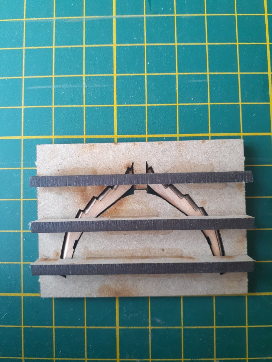
No idea, but perhaps the ropes were added at some much later date, and actually have nothing to do with the gun itself. Given that this is Gibraltar, maybe for the apes to swing on?? 😁😁 I'll retire quietly now.