Ed Ku20
-
Posts
239 -
Joined
-
Last visited
Content Type
Profiles
Forums
Gallery
Events
Everything posted by Ed Ku20
-
 Hi John! Thanks for the compliment. I'm looking forward to seeing you back at work on your Rattlesnake! Ed
 -
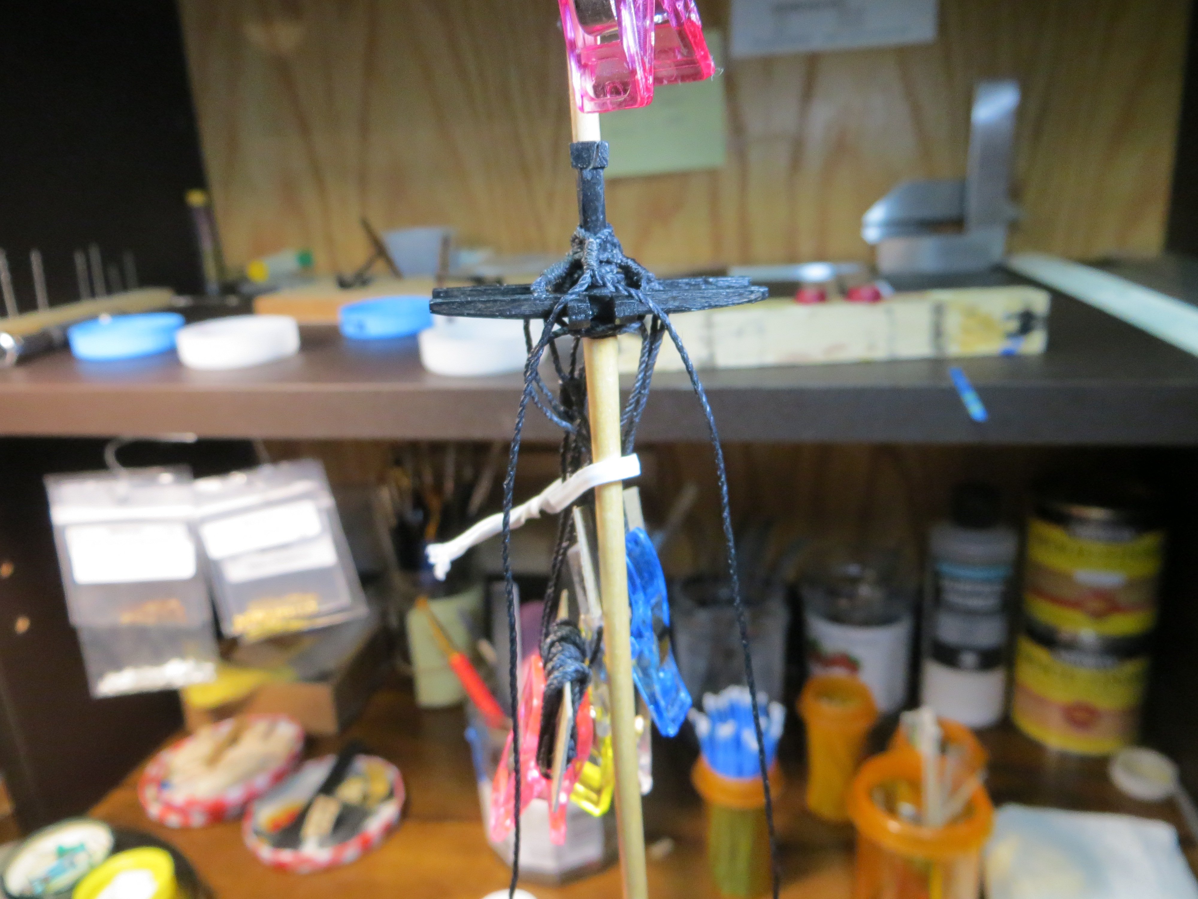
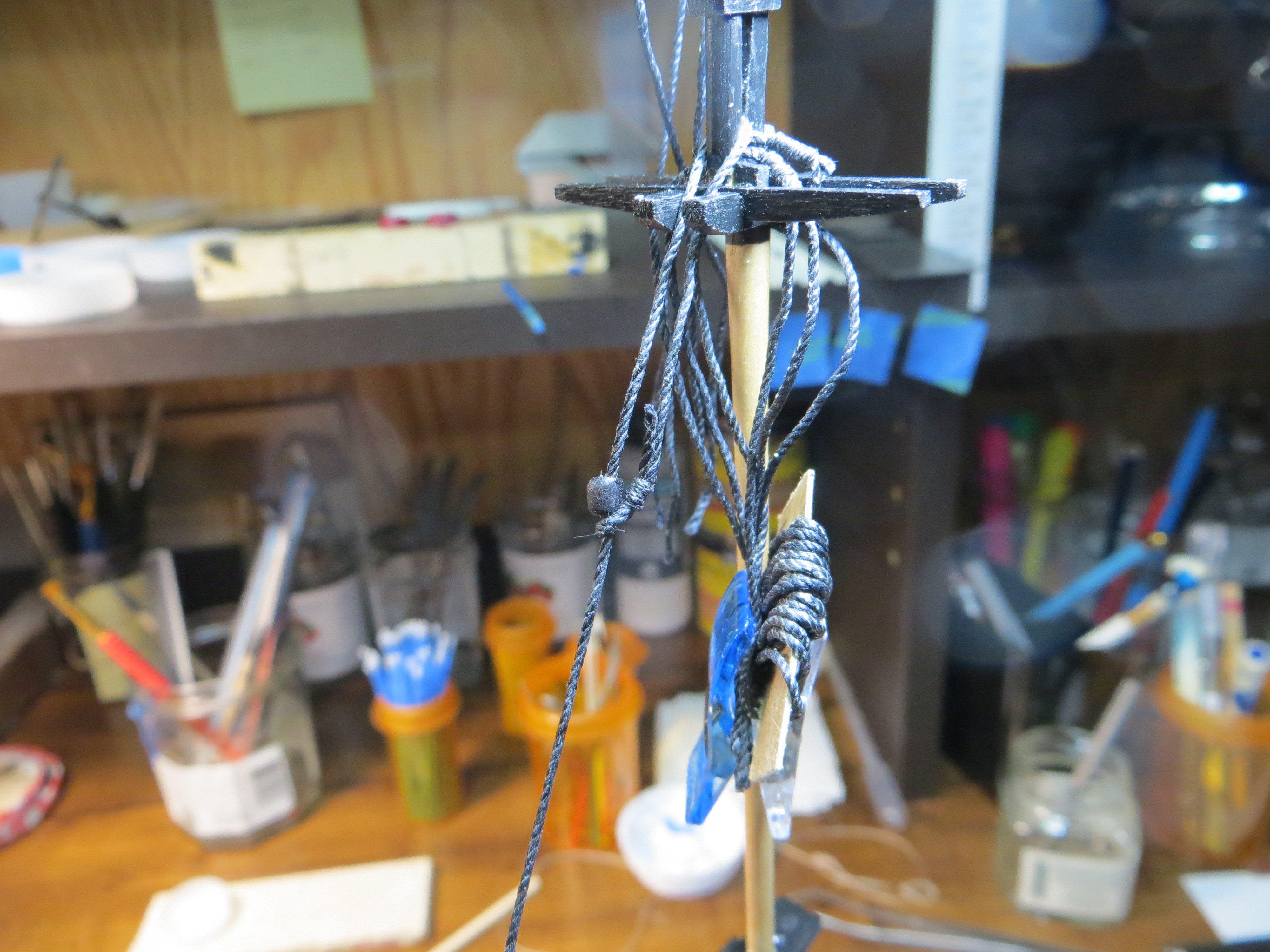
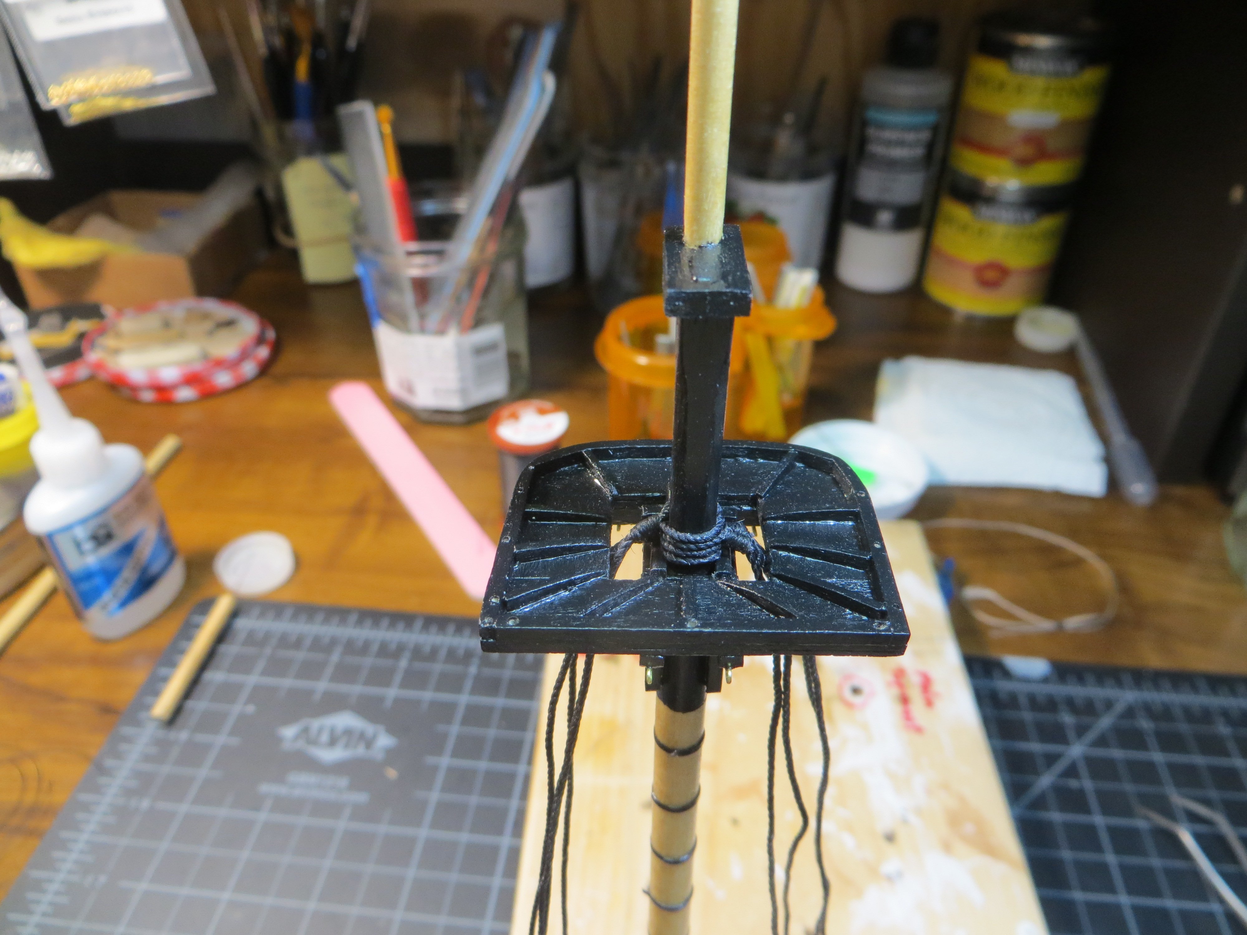
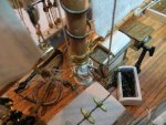
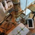
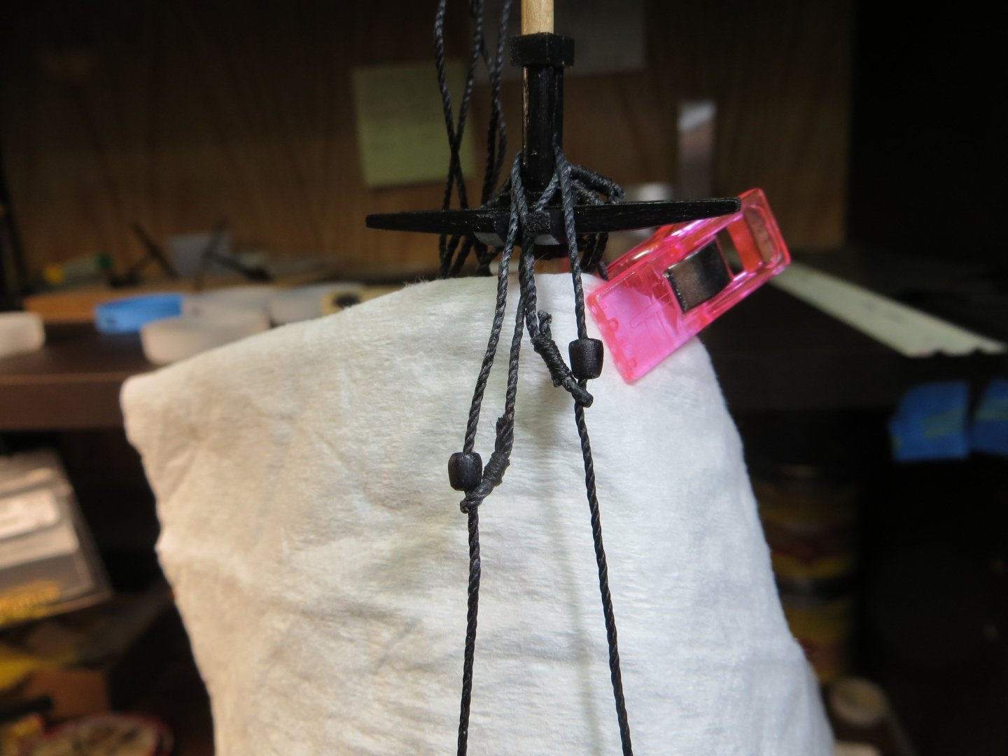
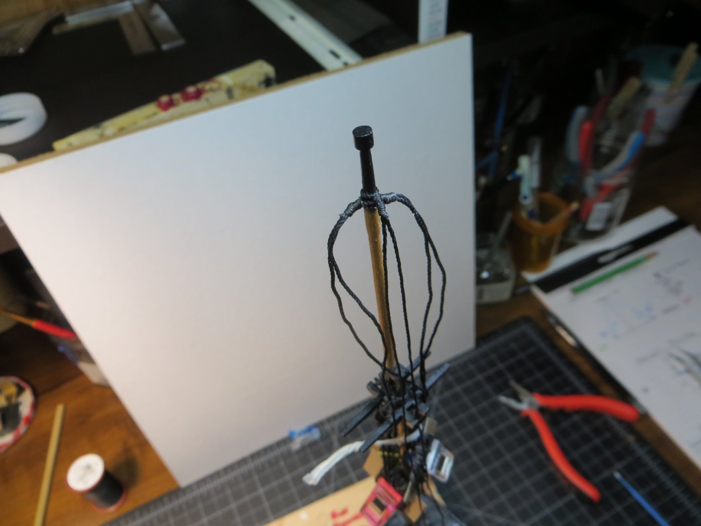
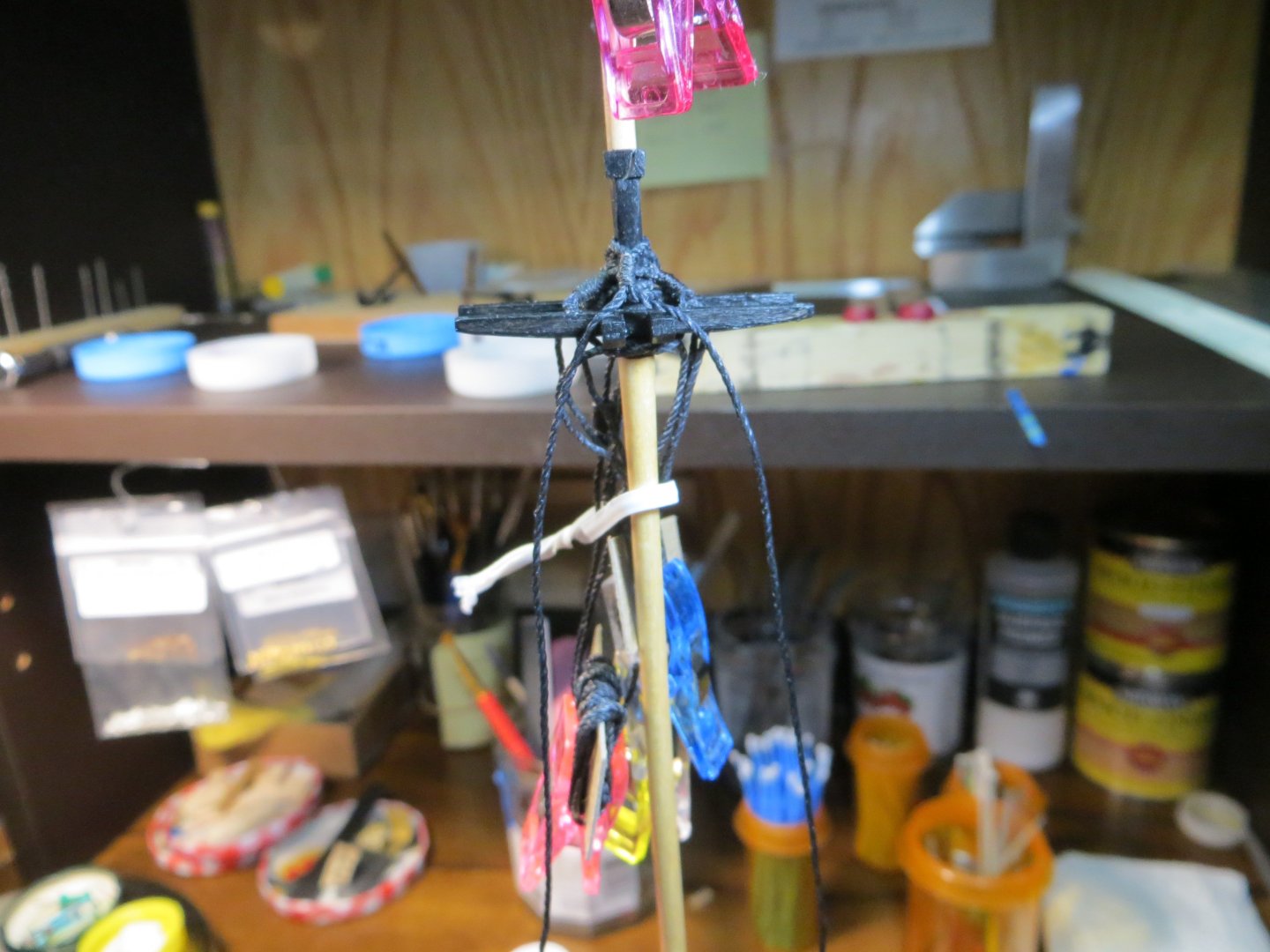
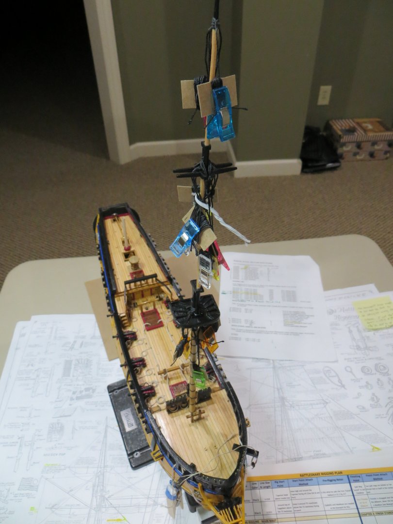
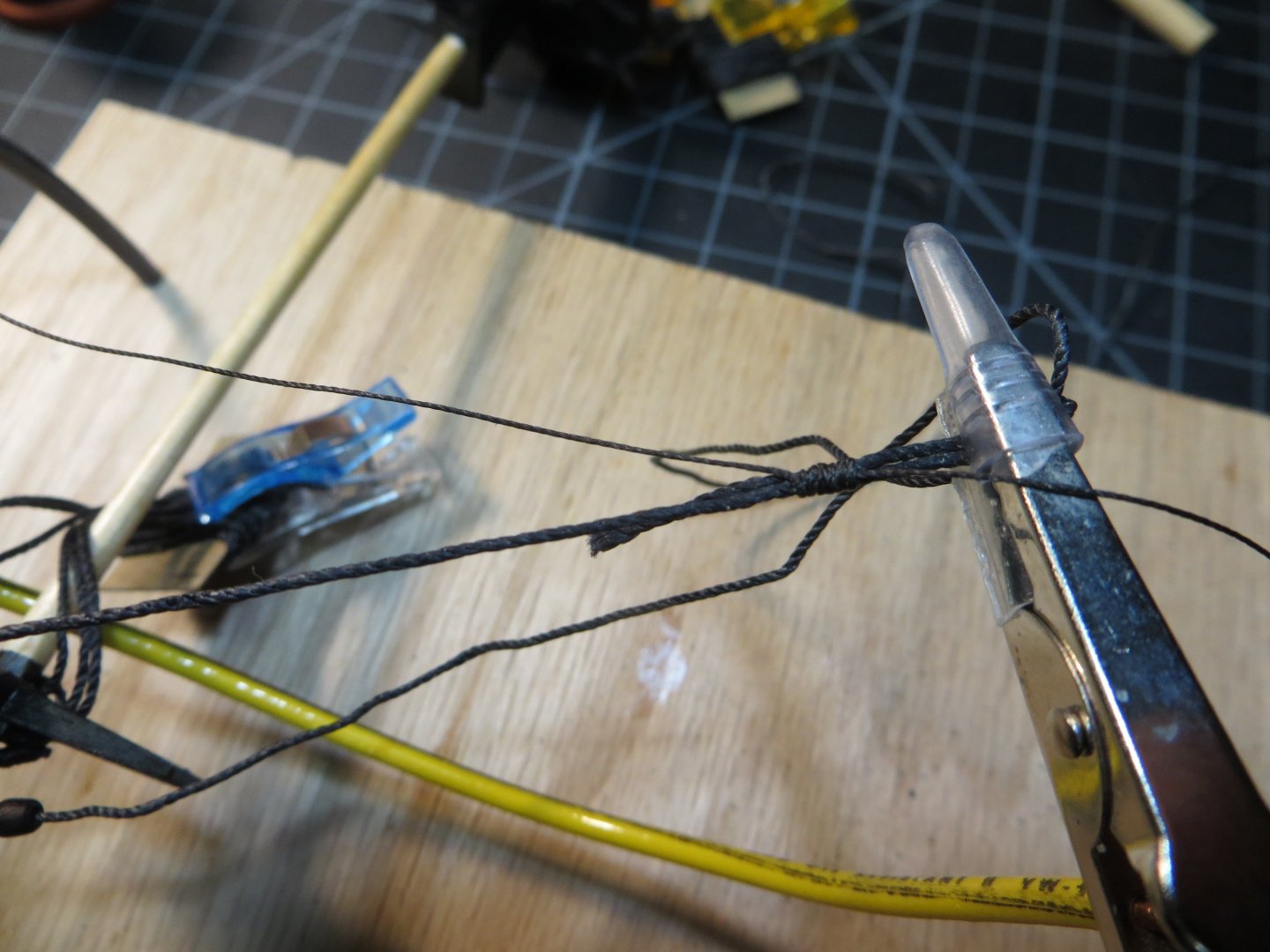
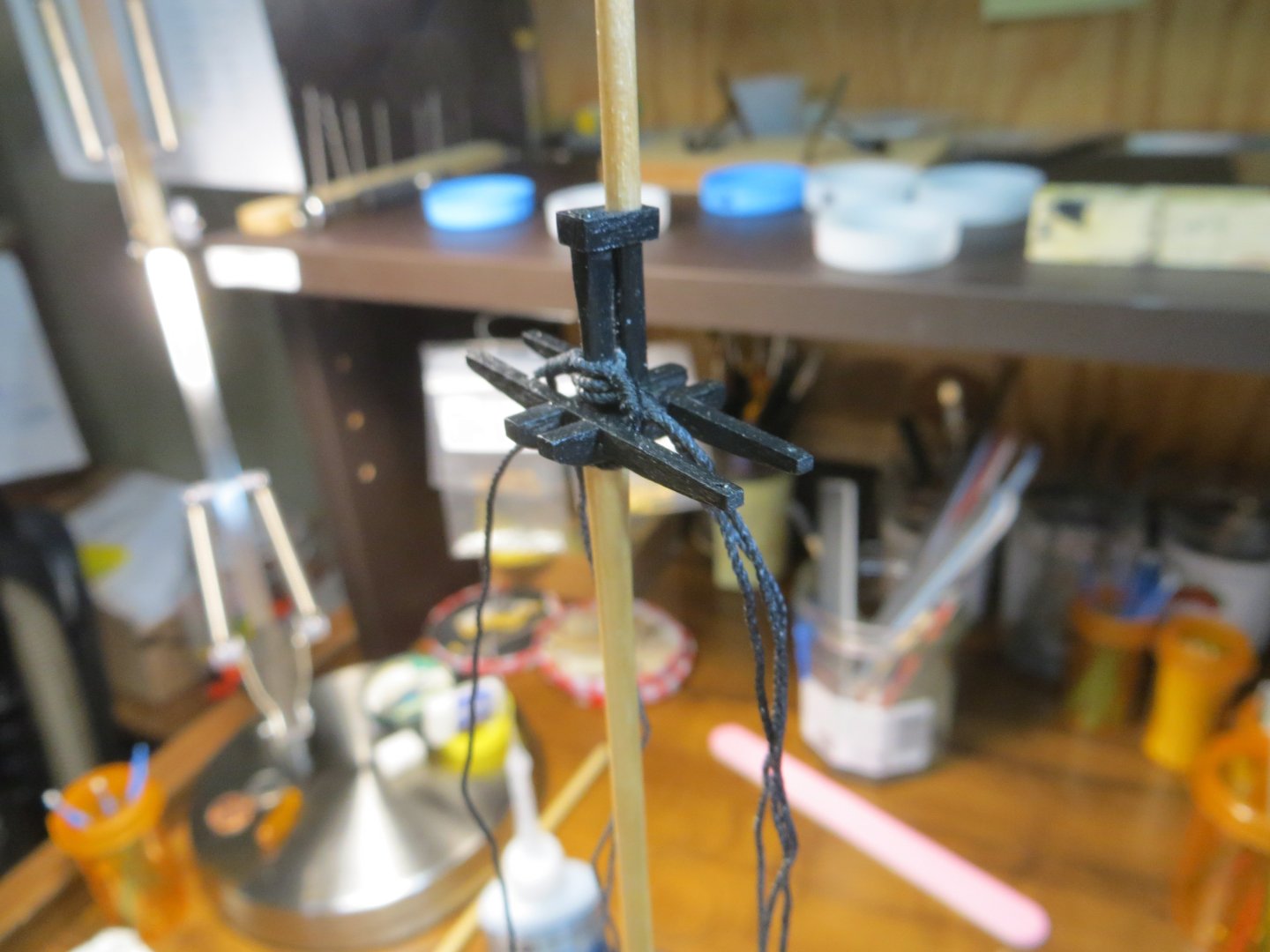
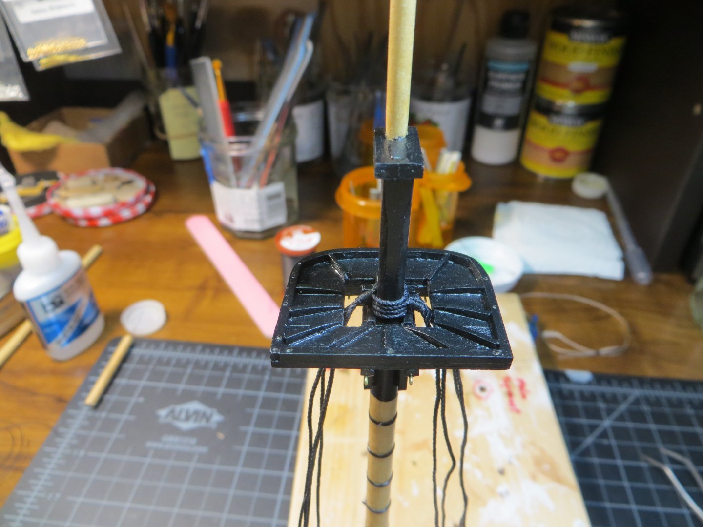
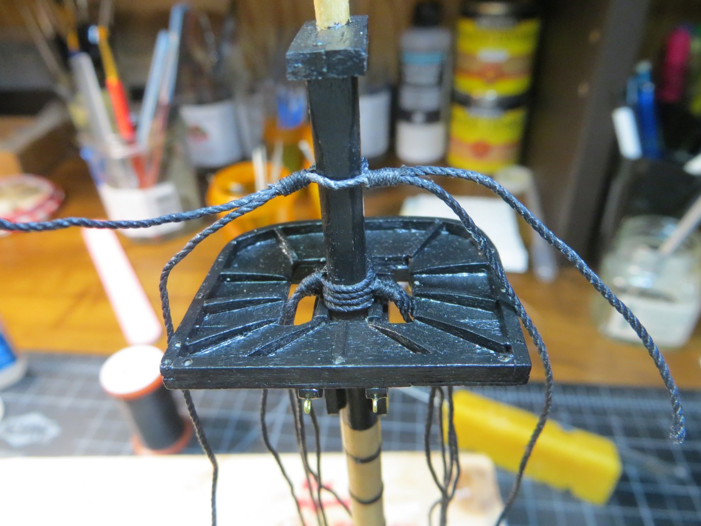
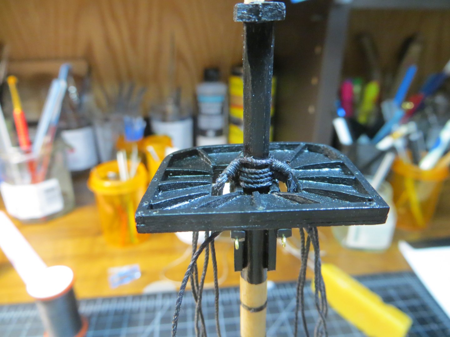
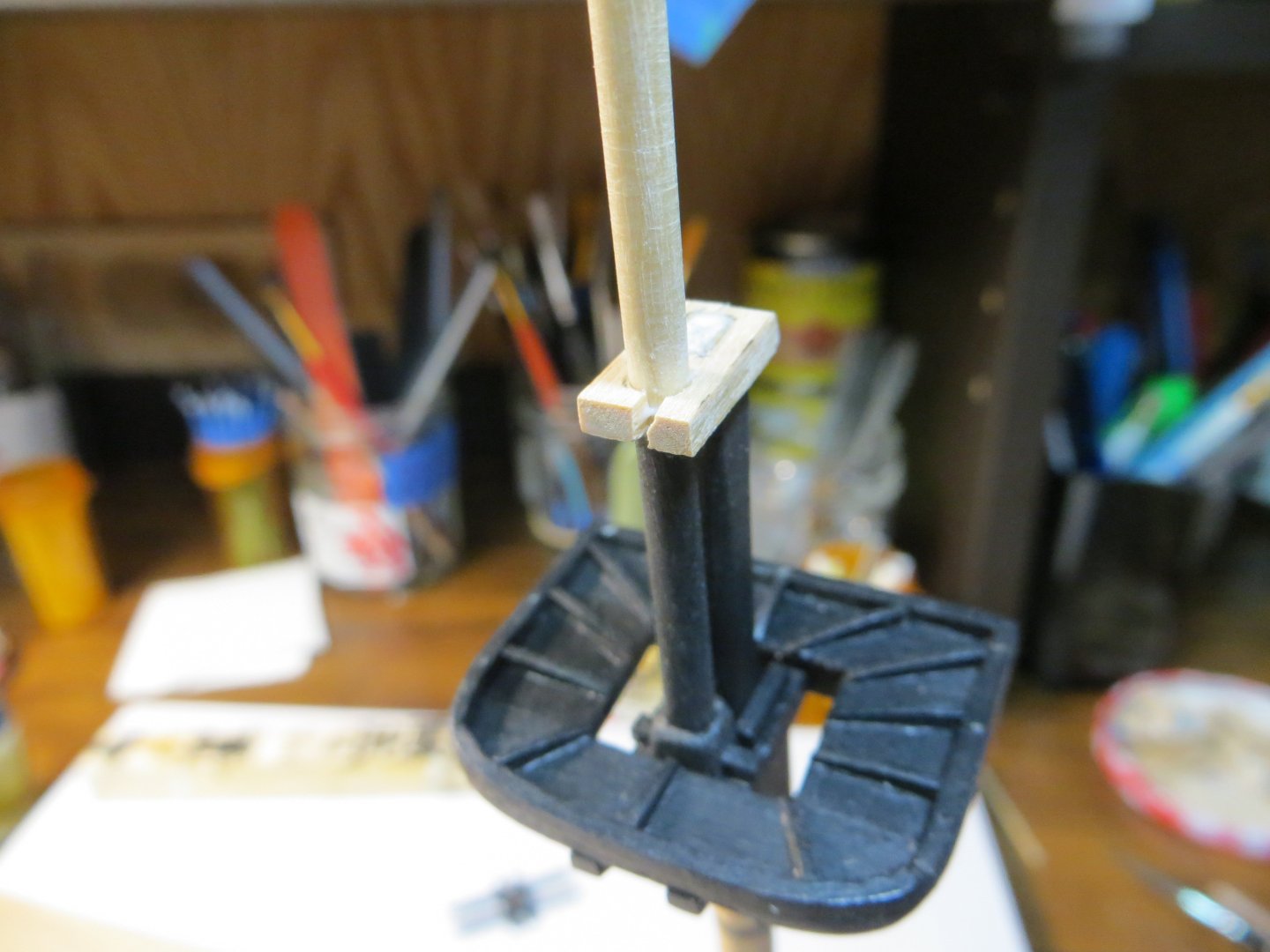
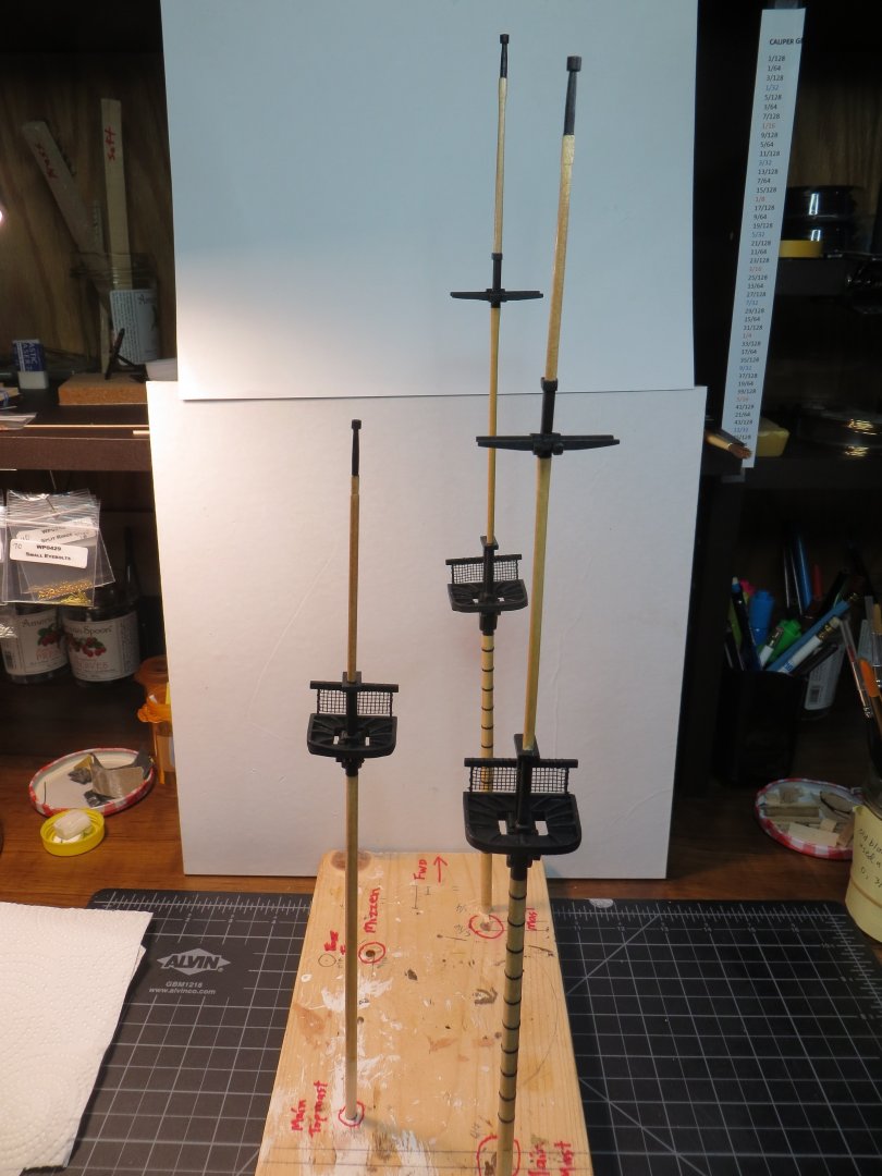
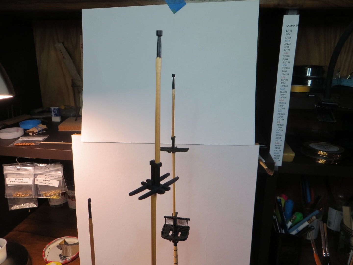
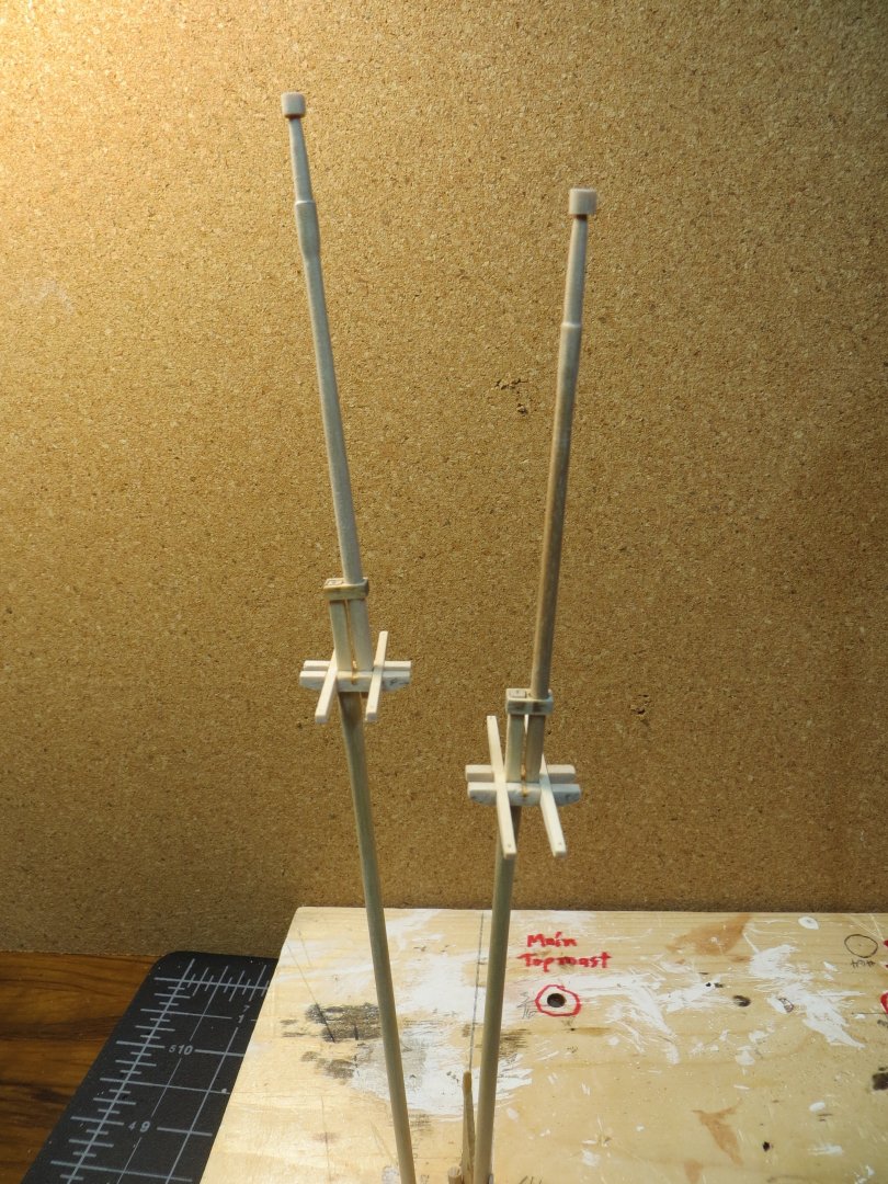
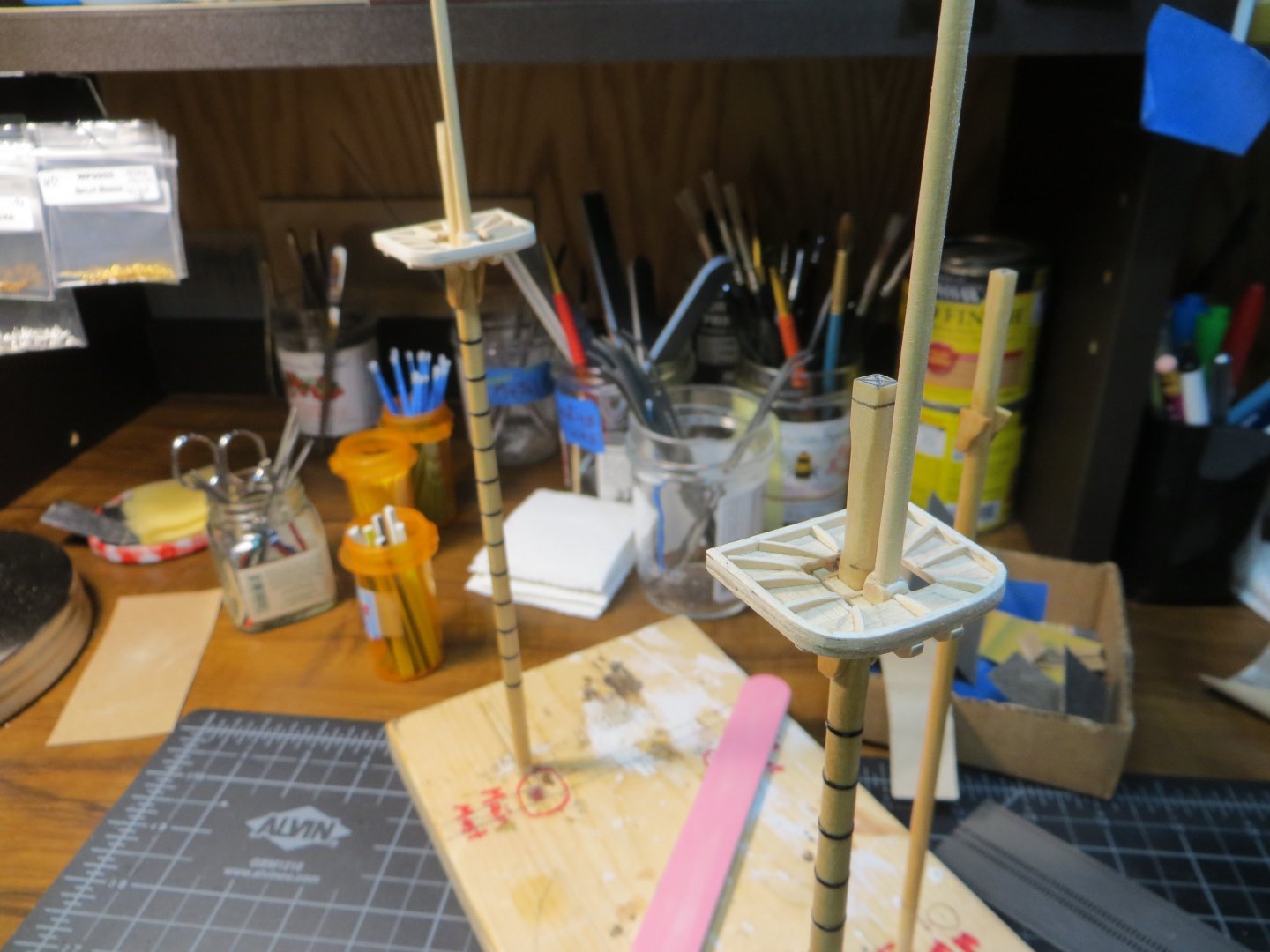
THE STANDING RIGGING (continued) Fore Topmast Stay Pre-rigging the Foremast continues. The Fore Topmast Stay is made exactly the same way as the Preventer Stay using a mouse with a long eyelet seized at the end. It is looped around the Fore Topmast at the trestle tree facing forward and sits on top of the Preventer Stay. It finishes by passing through the hole in the starboard side “Bees” on the Bowsprit. Attachment to the bowsprit will be completed later. Fore Jib Stay The Fore Jib Stay is the last forward-facing stay on the Topmast trestle tree. It also uses a mouse with a long eyelet seized. It finishes by passing through a sheave at the end of the Jibboom, through a piece of hardware called the Traveler and ends at a tackle with a pair of blocks attached to the bowsprit endcap. This will be completed later. Sorry, I don’t have a picture of this one. It looks just like the last two! Fore Topgallant Backstays Backstays face aft and hold the mast up from behind. A double length of rope is seized in the middle and then slipped over the Topgallant mast where it sits on top of the topgallant shrouds. One side goes to starboard and the other to port. They both finish with a tackle rig that is seized to an eyebolt in the outside of the hull just behind the foremast channels. This will be set-up later. Fore Topmast Backstays Another pair of backstays are attached above the Topmast trestle tree. A double length of rope is threaded around the head of the topmast facing aft. It is seized in the middle and sits on top of the Topmast shrouds. They are draped over the top of the trestle trees, one on each side, as seen in the following pic. They both finish in a difficult to explain tackle rig attached to the last foremast deadeye. That will be covered in detail later. Fore Topgallant Stay This is the final stay on the foremast. An eyelet is seized and slipped over the Topgallant mast facing forward where it is tightened up to the mast. This one also ends in a complicated rig at the bowsprit that includes a thimble, some deadeyes and eyebolts. This will be covered when completed later. This stay is coiled up and held by the blue clip in the pic below. This concludes the pre-rigging of the Foremast. I’m already working on the shrouds for the Main Mast. These are going more quickly because I’ve got the technique down now! I re-made the rope coils on the foremast because they were falling down for me. Here is what the Foremast looks like now with the pre-rig of the standing rigging completed. Thanks, Ed

-
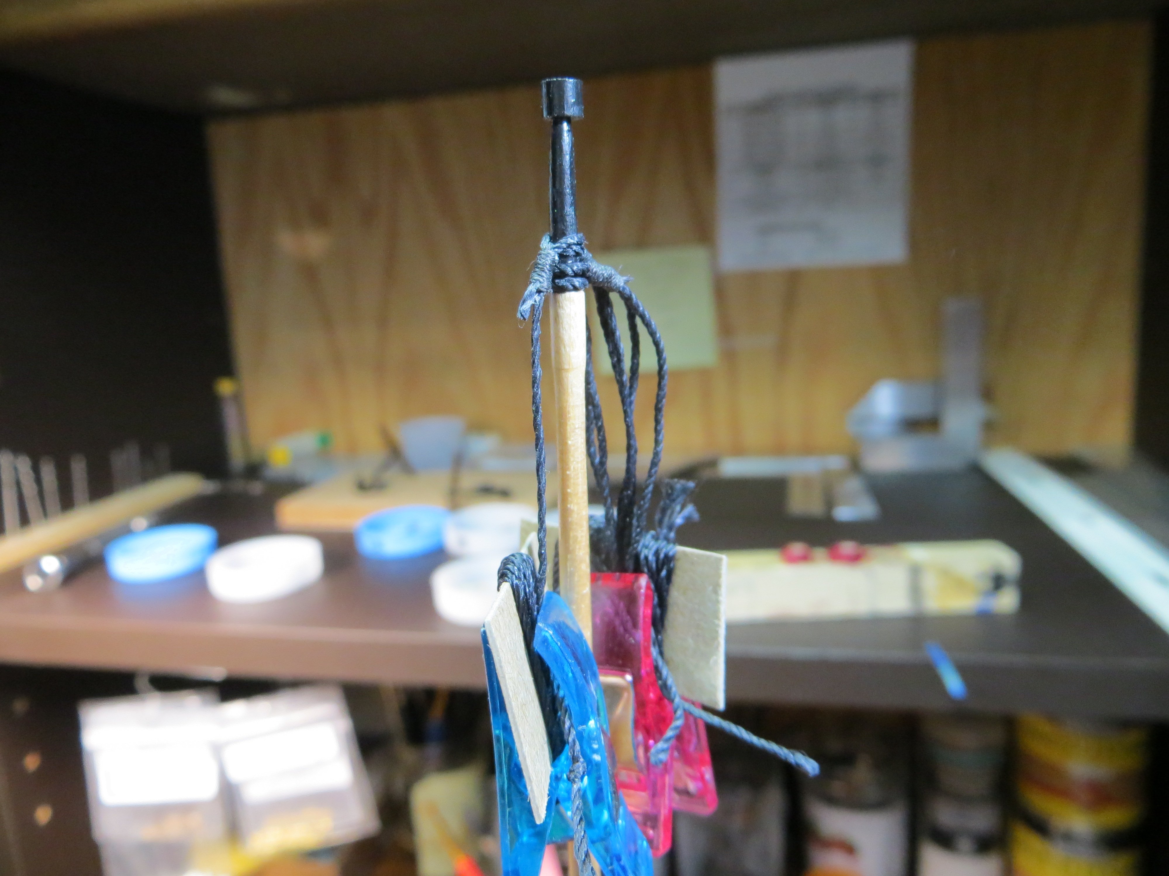
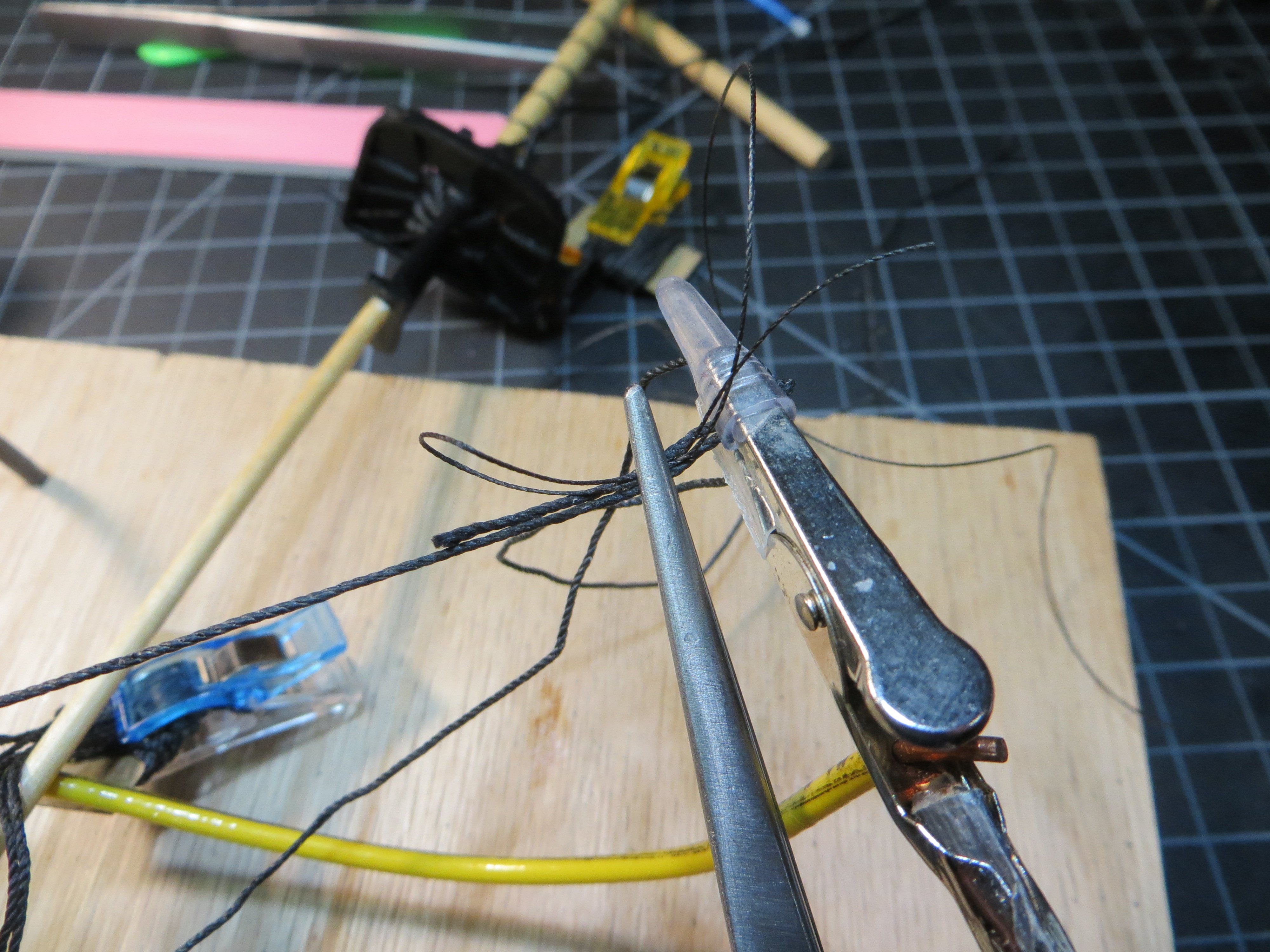
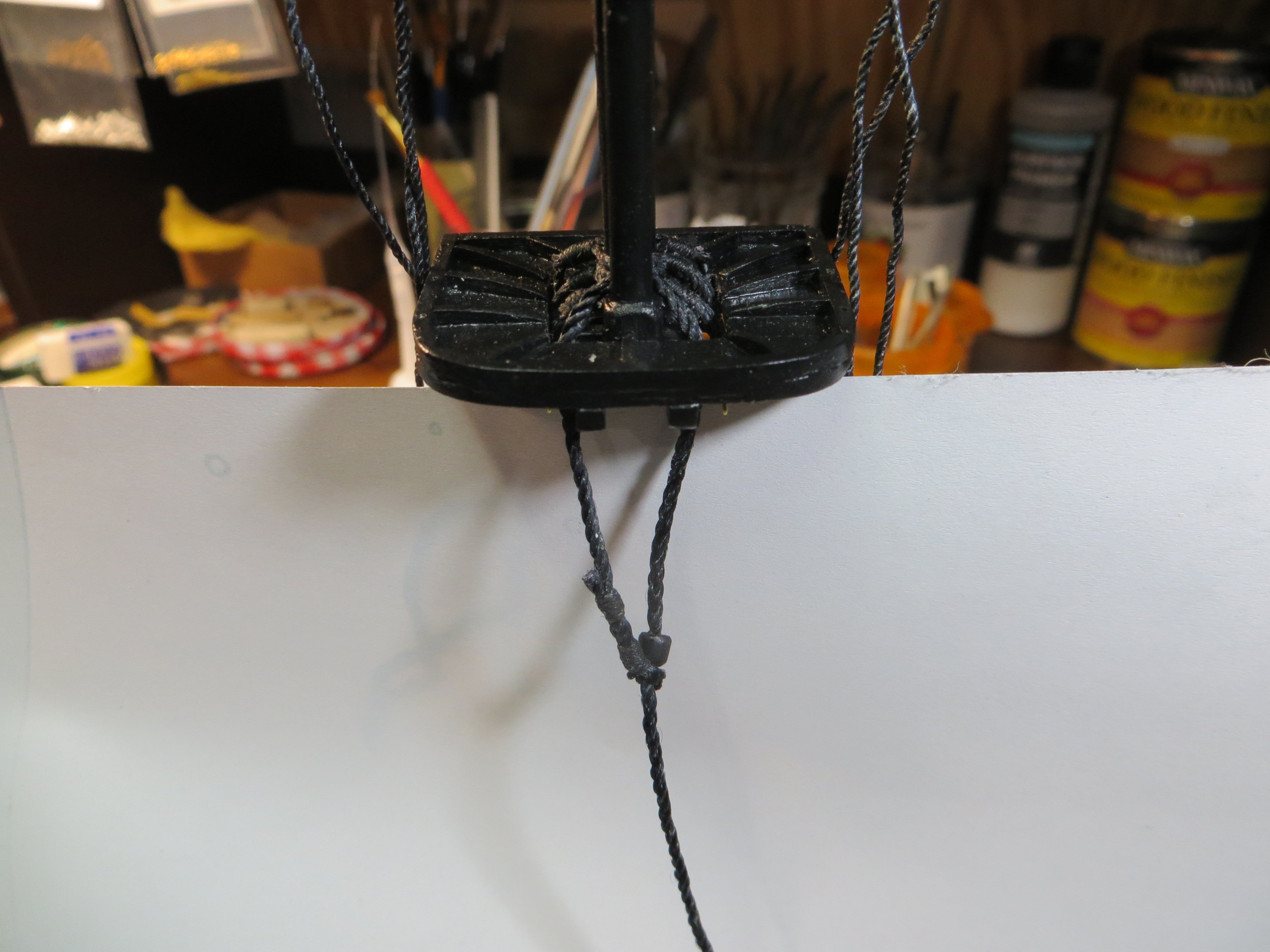
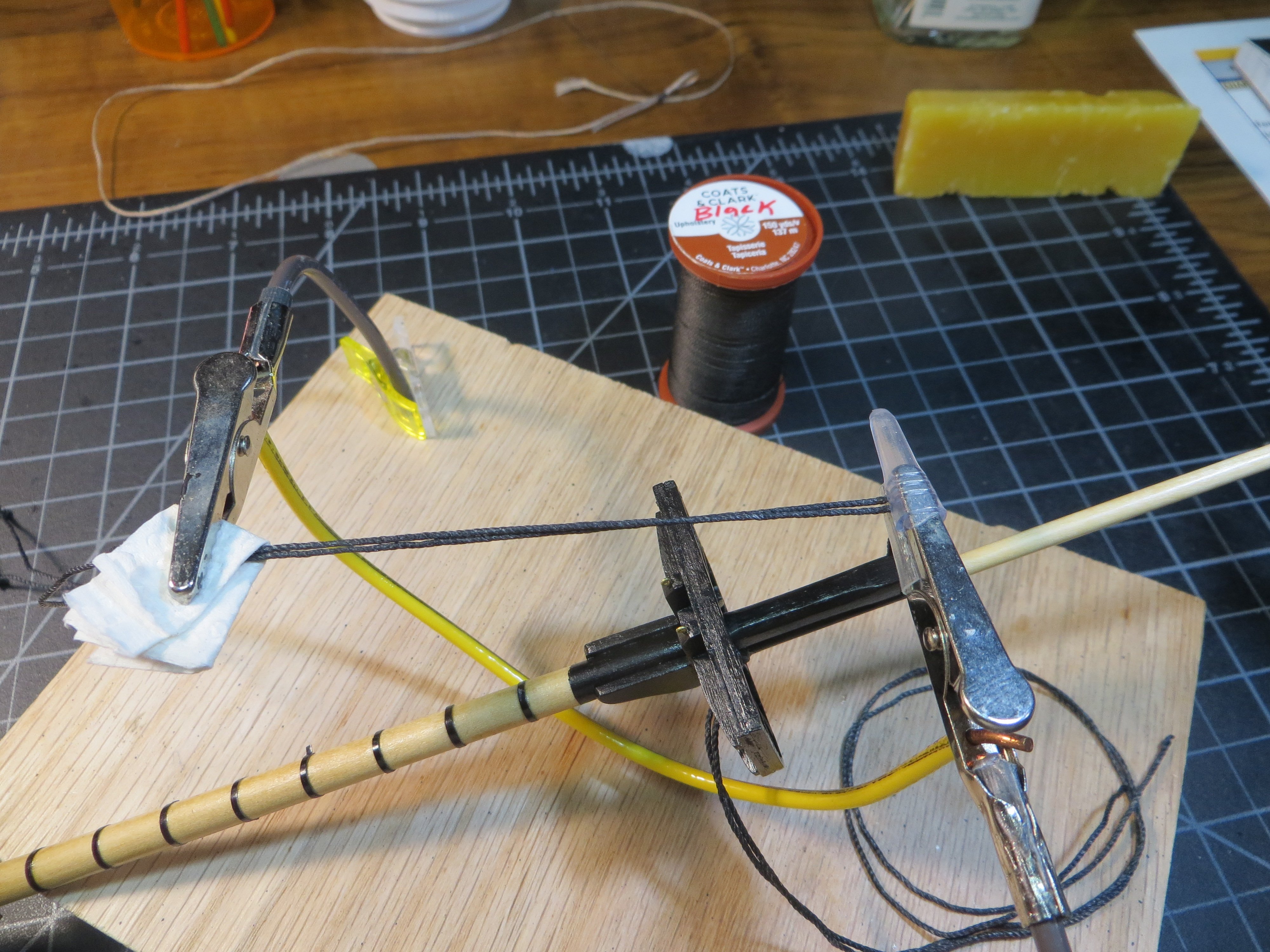
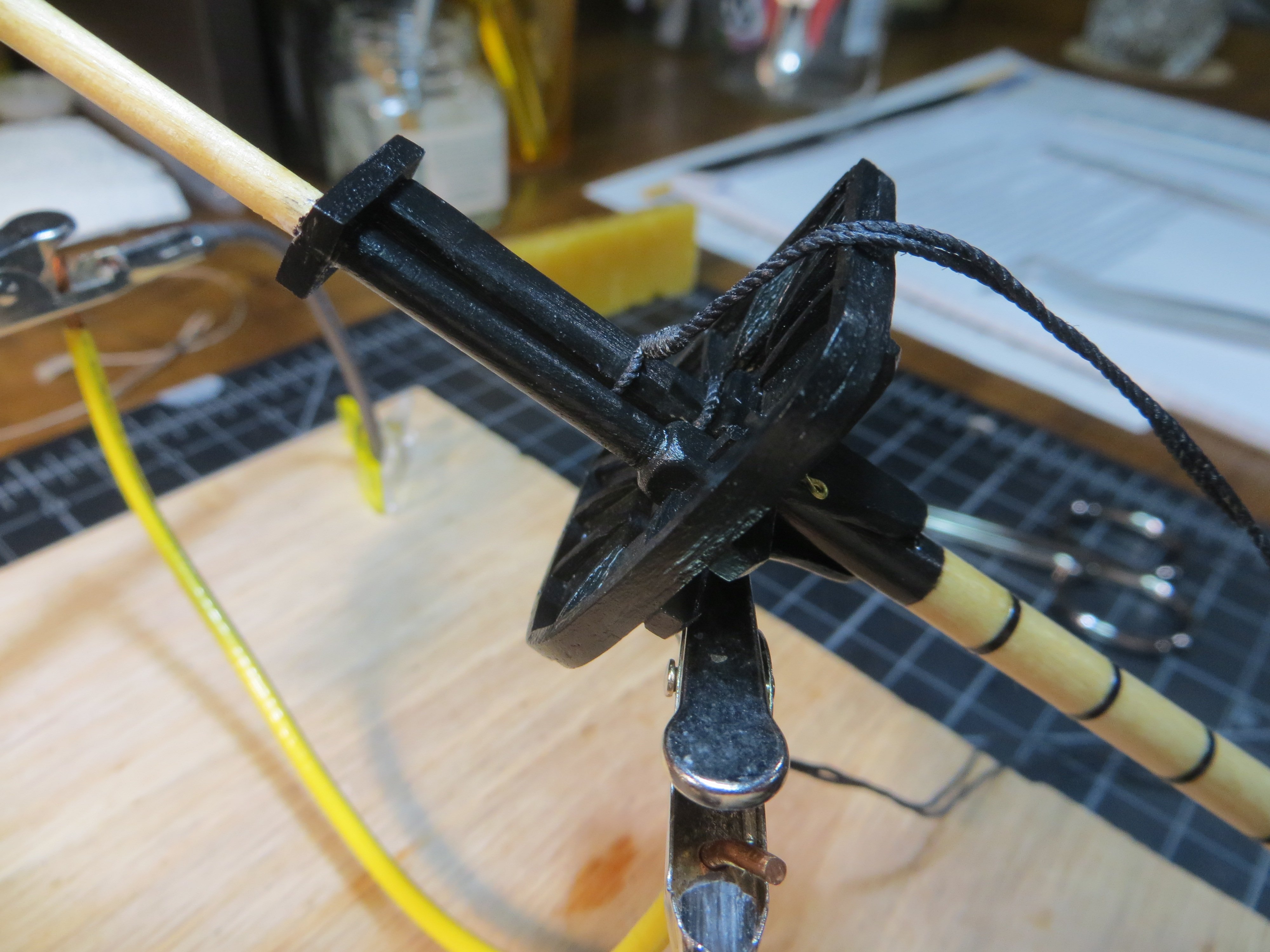
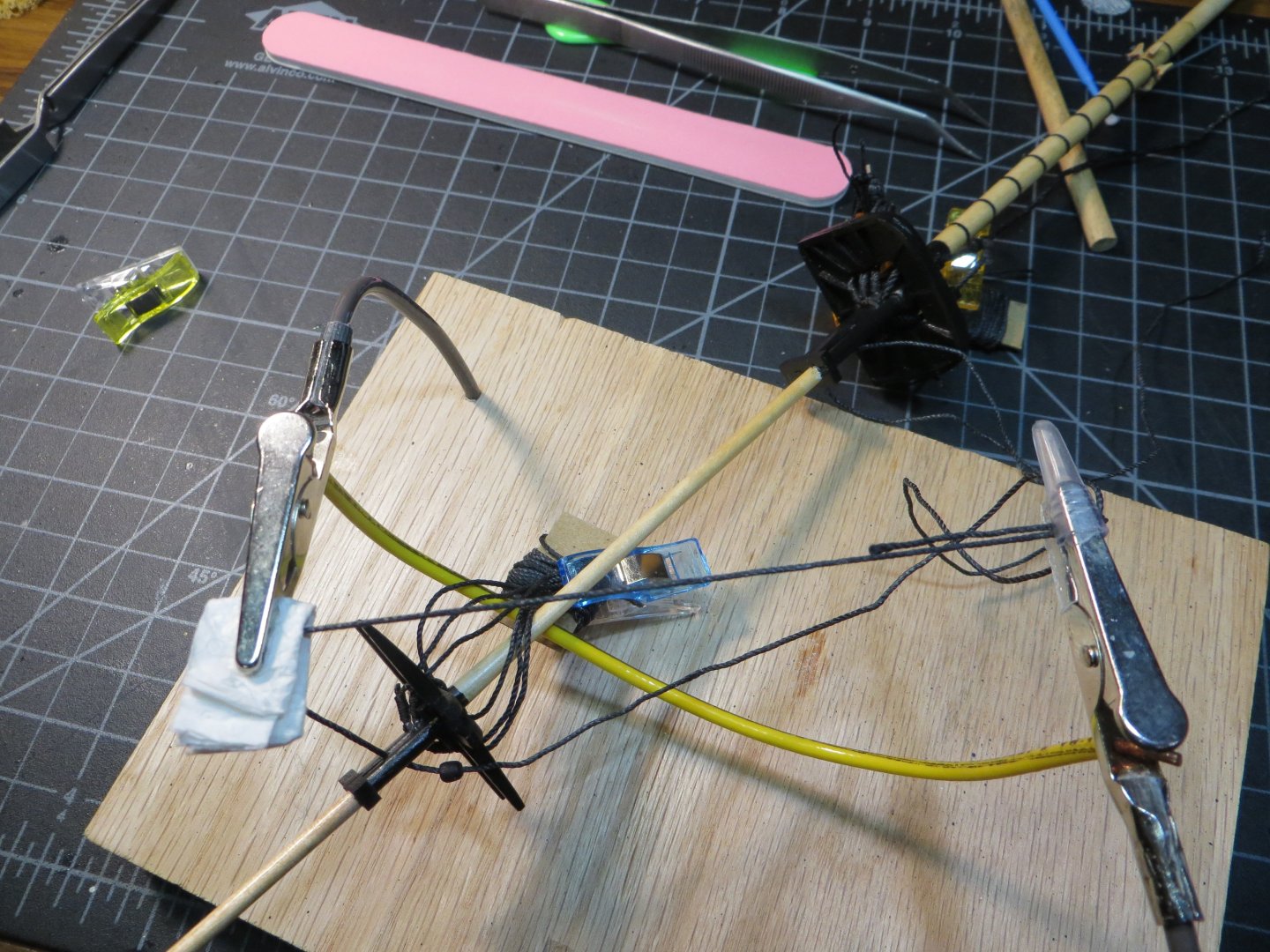
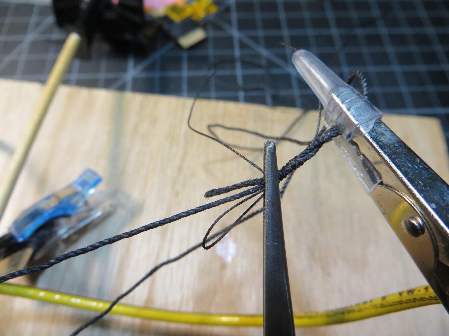
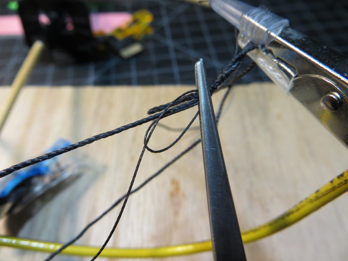
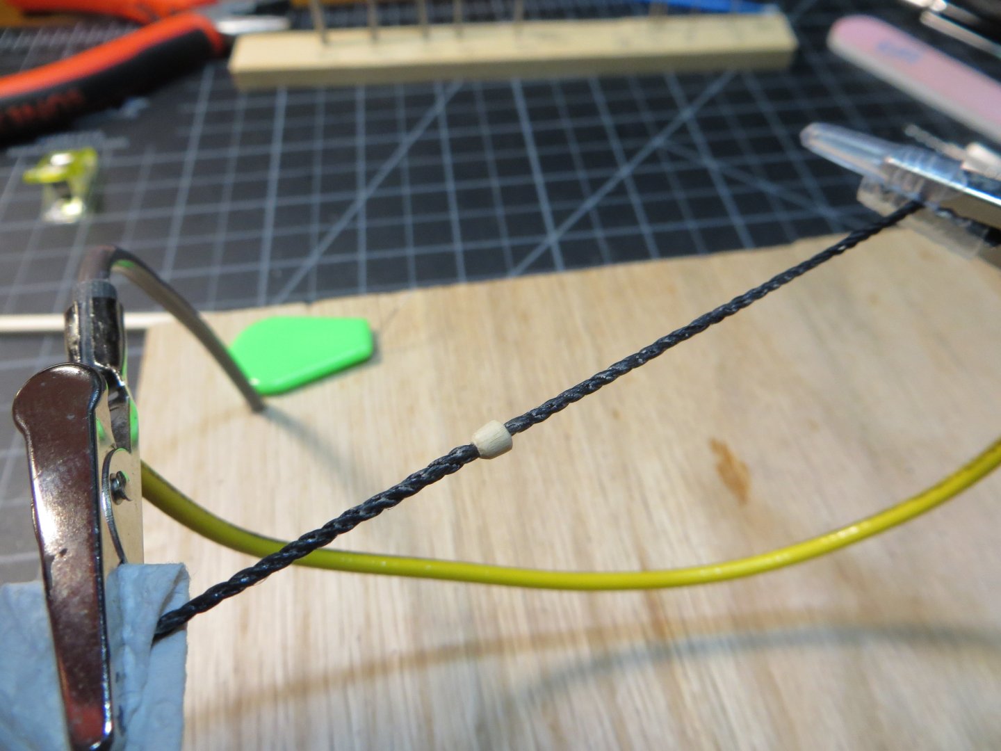
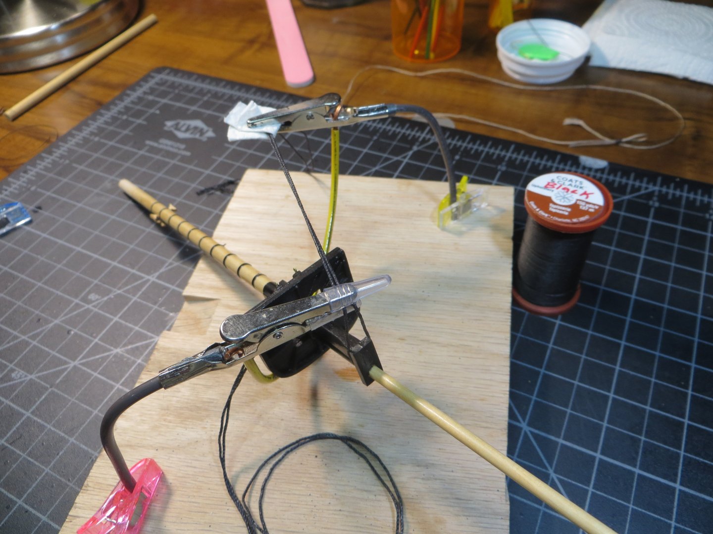
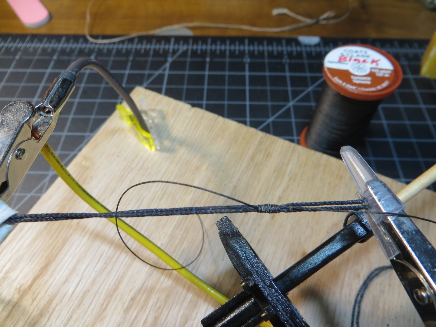
THE STANDING RIGGING (continued) Fore Topmast Preventer Stay The Preventer Stay is seized around the topmast same as the Fore Stay. A long eyelet is seized with a mouse after passing through the topmast trestle tree. I pre-rigged this side. It finishes by passing through the hole in the port side “Bees” on the Bowsprit. This will be completed later. To make the seizing on each piece of rigging I used the method demonstrated by Robert Hunt, whose Rigging Practicum I am using on the Rattlesnake. Here is the link to his YouTube. This is for a shroud, but the technique is the same for an eyelet. https://www.youtube.com/watch?v=Vqo5zXsZ7Ak He makes it look way easier to do then I can execute! But I’m getting better. Here are a few pics of my own adaptation of his technique. In these pics I’m making the eyelet on the end of the shroud that the mouse is preventing from sliding up the stay. This can be seen in the last pic below. The stay has to pass thru the space between the topmast and topgallant at the trestle tree. The mouse needs to be in the middle on the other side of that space. The stay has to be inside the eyelet like a lasso. 1. The stay is set-up in the helping hands jig. You can see the trestle tree and mouse positioned on the left. The end of the stay is folded over to form the eyelet which is held in the clamp on the right. 2. An 8 to 10-inch piece of black thread is made into a loop that is held by the tweezers (just so I can take the picture; otherwise, I’m using my fingers). Both ends of the thread are on the right side of the tweezers. There is a short end and a long end for the thread. 3. The long end is wrapped around both the stay and the loop while I am holding them together in my fingers. I again clamped it to keep it from unraveling while I take the pic! 4. After wrapping it about 10 times using the long end of the thread, I pass this end through the loop. 5. Hold the left side of the wrapped seizing with on hand and gently pull on the short end on the right side with your other hand. Make sure the left end doesn’t get tangled while the loop gets pulled up to the seizing. When the loop gets right next to the left side of the seizing hold the ropes for the stay tight and continue to pull the loop inside of the seizing. Don’t pull it through completely or you’ll wreck all your work! I just try to get it about 3 or 4 wraps into the seizing. 6. Now I remove everything from the helping hands and use a tweezer to slide the seizing up into position. I add a drop of CA glue to hold everything together after I’m sure it’s in the right spot. Then cut the loose ends off. Here is the completed Preventer Stay attached to the Fore Topmast above the trestle tree Hopefully the notes above are understandable! If not, the video is pretty good. Next up is the Fore Topmast Stay. Thanks, Ed


-
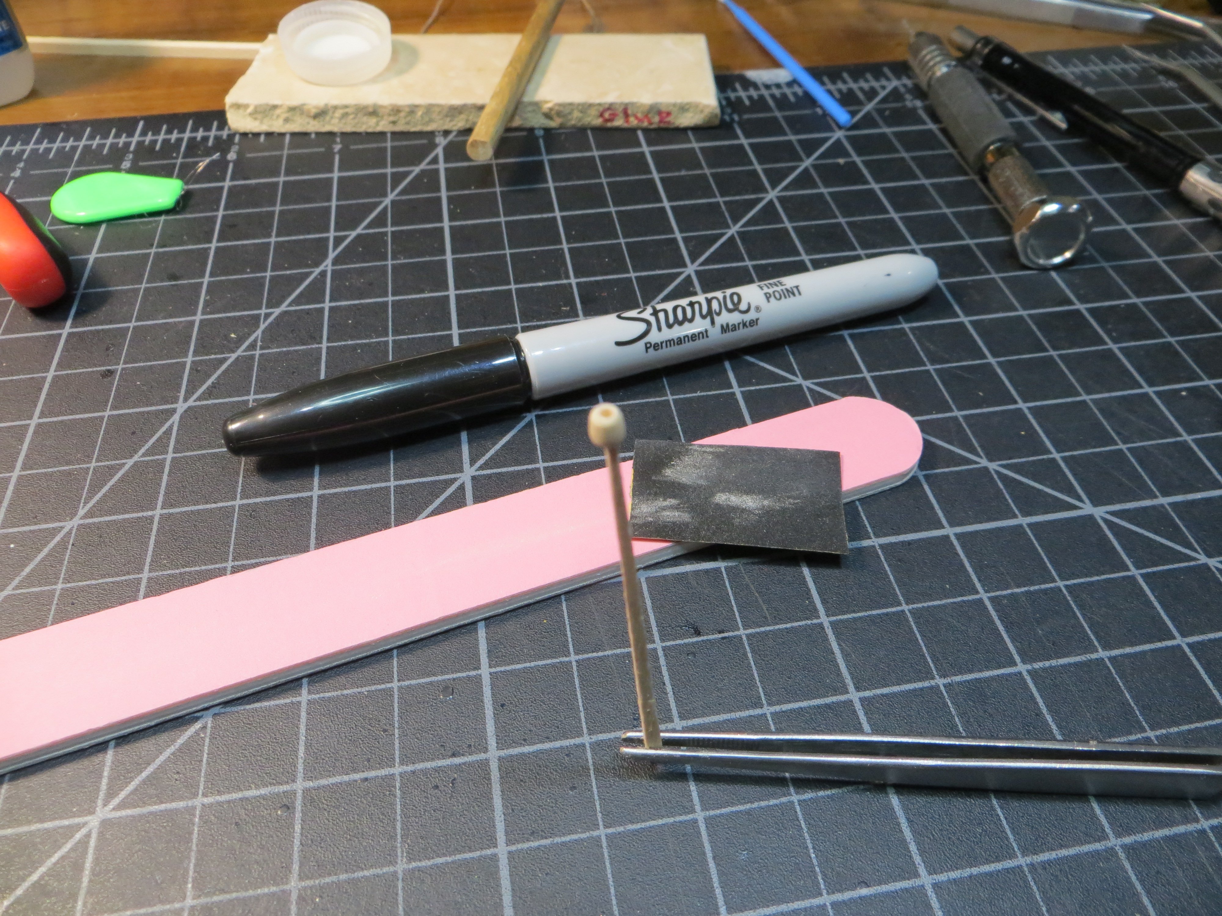
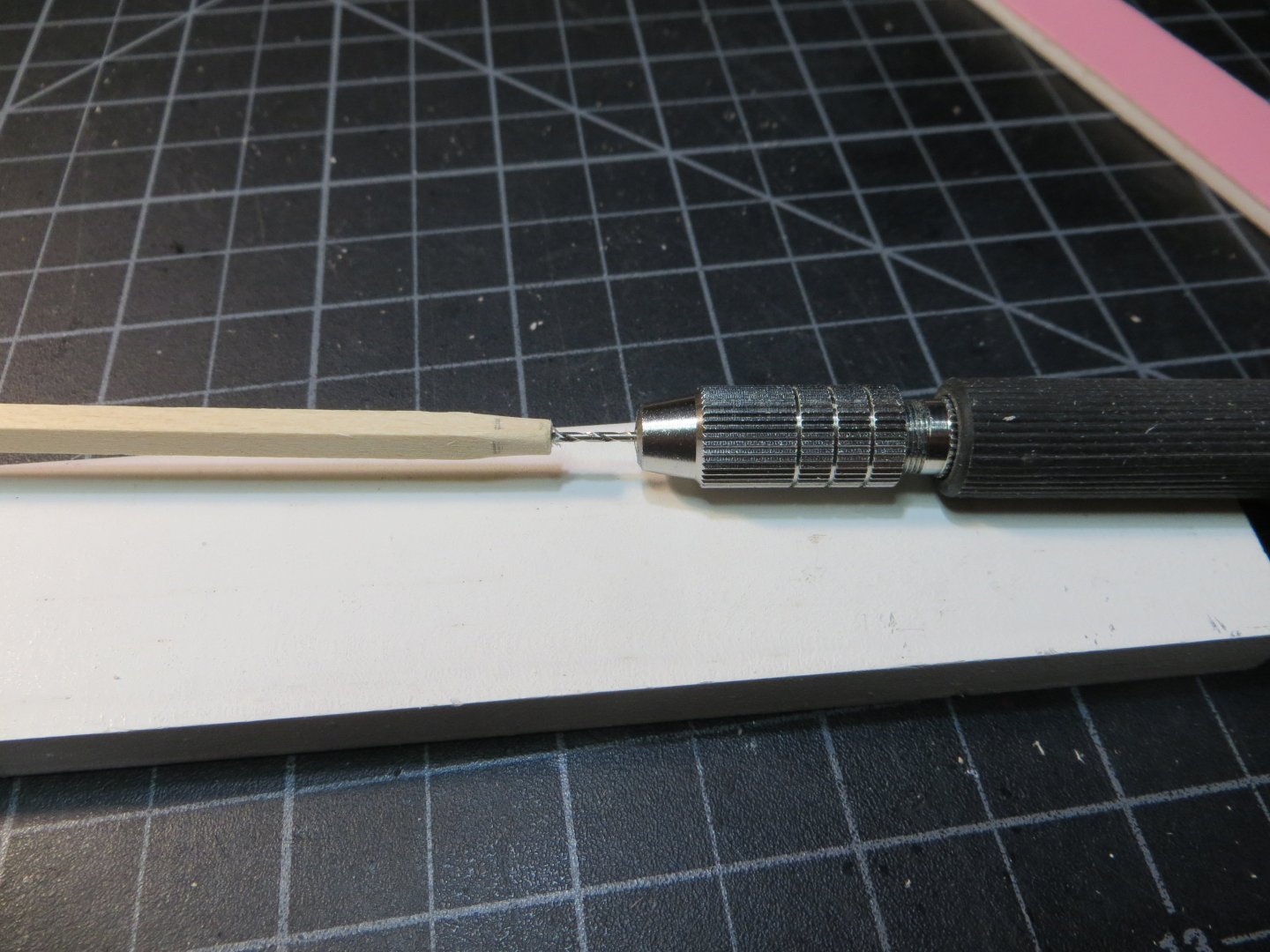
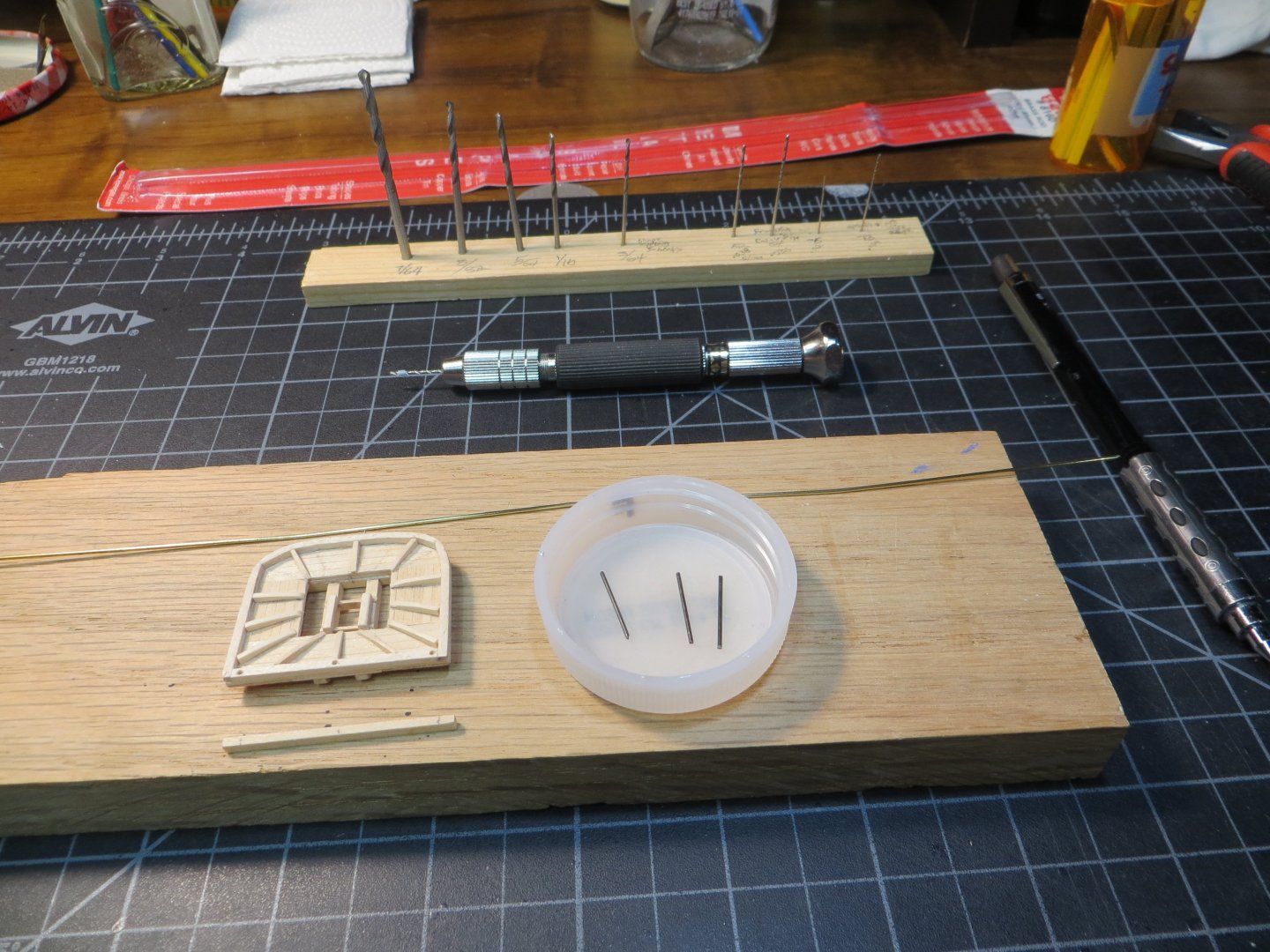
THE STANDING RIGGING (continued) Foremast Topmast Shrouds The Topmast has 3 shrouds on each side. The first pair is attached to the topmast trestle tree on the starboard side. The next pair goes on top of that facing the port side. Shroud #3 is a single that is made the same way as described for the single #5 shroud on the lower mast. The ends of the single extend on both the starboard and port sides, facing aft. A short line is seized to the middle of the longer shroud. The steps for attaching these are the same as described for the lower mast shrouds. The 3 shrouds are attached to the foremast trestle tree Foremast Topgallant Shrouds The Topgallant has one pair of shrouds on each side. These attach above the notched area near the top of the topgallant mast. Below is a pic of this. Here is a pic of the foremast with all shrouds attached. I coiled up the lower shrouds to keep them out of the way The Foremast Stays The next rigging lines are the Stays. This type of rigging supports the masts from forward to aft. There are 5 Stays on the Foremast. They all extend from the Foremast to the Bowsprit. As with the shrouds these are going to be “pre-rigged” on the Foremast. They will be attached to the bowsprit later. The first 4 Stays use a “Mouse” to attach the stay to the foremast. On the ship this is a ball of woven rope that holds the stay in position at the mast end. On the model the practicum has you simulate the Mouse with a small piece of stripwood. I will detail the steps for making a mouse on the Fore Stay. Fore Stay The Fore Stay is one of the heaviest ropes on the ship. I am using the 0.04” black rope provided in the kit. This rigging starts at the masthead of the lower foremast, threads through the fighting top around the trestle tree and is attached to the Bowsprit with an Open & Closed Heart that will be setup later. I measured the amount of rope required (allowing extra), cut it and coated it with beeswax. Then I made the “Mouse”. Method for making a Mouse – a piece of 1/8” x 1/8” square stripwood is selected and a hole is drilled in the top of it that is close to the size of the rope. I used a #64 bit in my pin vise for the 0.04” line. Some of these pictures are out of order because I took various shots while I made the 4 of them over the course of a few days. This picture shows the hole after rounding off the square stripwood The pin vise in the stripwood later on when making the next mouse by extending the original hole deeper The first end is sanded into shape while it is still on the stripwood then I cut off at 1/8” long and shaped it some more into a wedge. After losing the first one in the carpet, I sanded down a toothpick to hold it! Sorry about the poor focus. I colored it black using a Sharpie Test fitting the first one to make sure I could get it on the rope. This gives you a good idea of the shape A “long eyelet” with 2 seizing’s needed to be rigged in the helping hands jig. The trick with the jig was threading the rope between the two masts and getting the mouse in between the eyelet, facing the right direction and wrapping the eye around the stay in proper order! After a couple of false starts, I finally figured it out. Here is the finished product below. I will cover how I did the seizing on the Preventer Stay in the next post. I’m moving along pretty quickly now so I will make a few shorter posts as I progress. Plus, the steps will get repetitive as I go along. It’s 13 degrees this morning and getting colder! Stay warm if you got my weather too! It’ll be a great day to work on the ship and watch playoff football. Thanks, Ed


-
Jason, Great to hear from someone else who likes rigging! I picked Rattlesnake for the cannons and its beautiful square rigging. Appreciate your following along! Thanks everyone else who is following along, for your encouragement! Ed
-
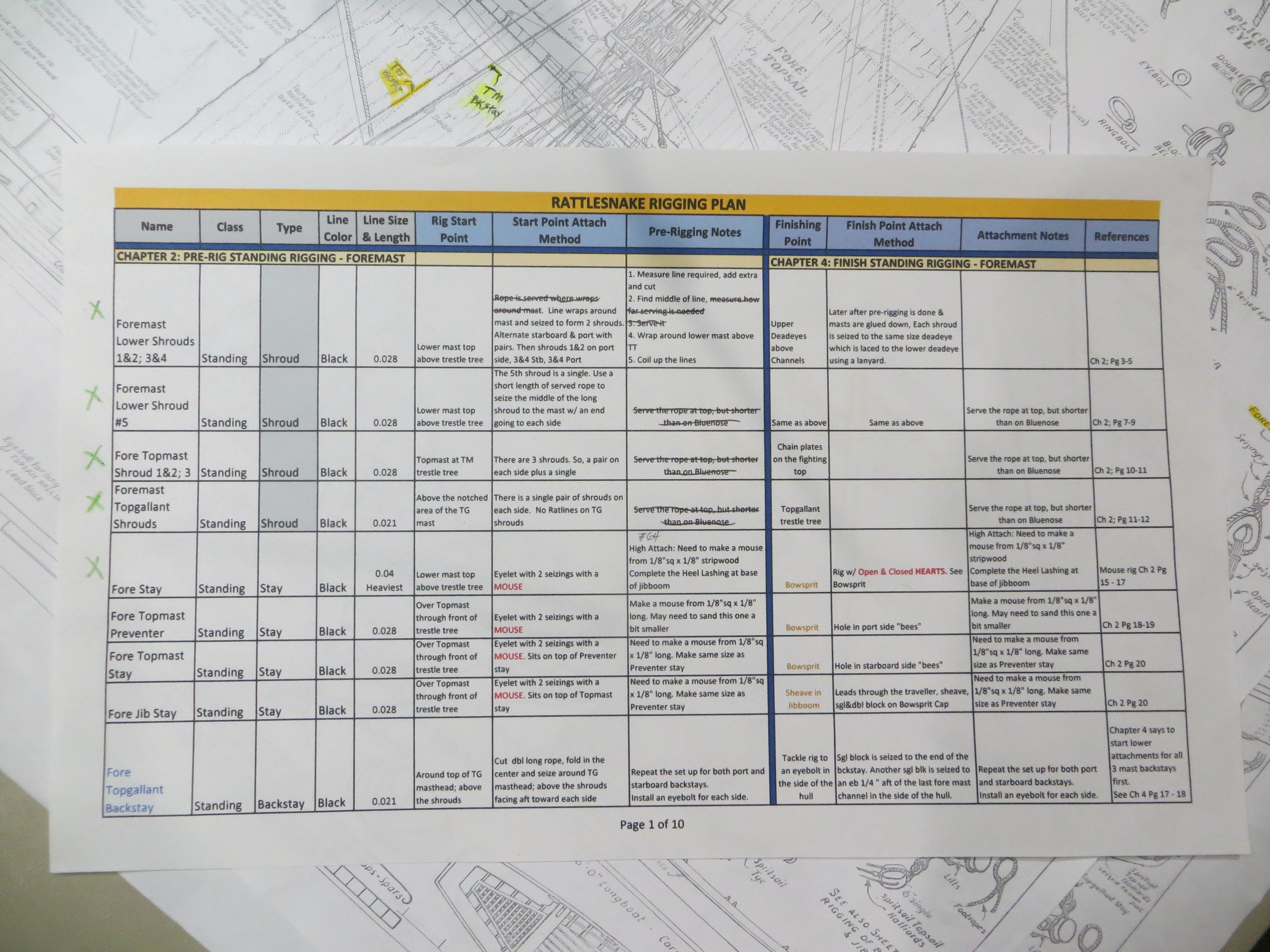
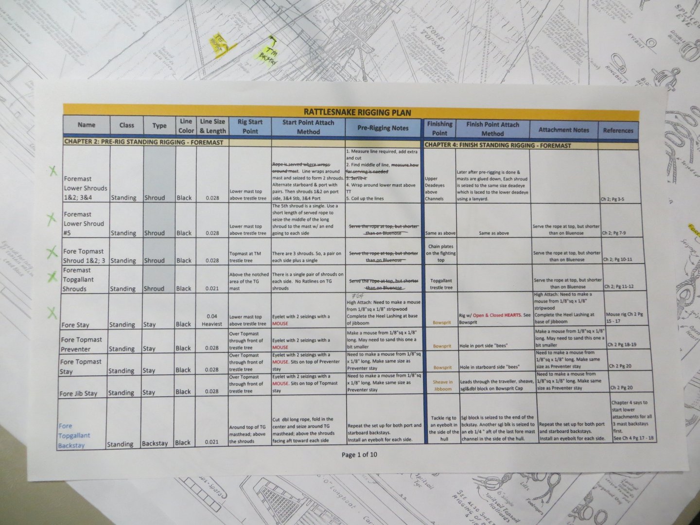
START RIGGING RATTLESNAKE Introduction I’ve reached a major milestone. Except for a couple of items I’m holding back until I’m further along with rigging, I am finished with the basic ship construction. It’s time for rigging. Some people don’t like this step. I actually enjoy it! I like trying to figure how each of the lines works and applying the dexterity required to do a neat job. The rigging on Rattlesnake is complex, in my humble opinion! To help me do the job well, I purchased Bob Hunt’s Junior Course on Rattlesnake Masting & Rigging. That is my primary source, but I’m also using the MS plans and Jon Gerson’s build log. I spent the month of December compiling information into a Rigging Plan same as I did with Bluenose. It is currently 10 legal size pages long printed from an Excel spreadsheet. Below is a pic of the first page from my plan. On the left side of the vertical blue line is the pre-rigging starting point for every line. This corresponds to Chapter 2 for the standing rigging in the practicum. All the pre-rigging will be done “off the ship”. On the right side is the finishing point for the same lines. This corresponds to Chapter 4 for the standing rigging. When I get to the Running rigging these are covered in Chapters 3 and 5. I couldn’t complete Chapter 5. Belaying these lines is too difficult for me to figure out yet. But that will come in time! I’m using the kit supplied rope. I did that with Bluenose and thought it turned out well. I ended up taking all the rope sizes from the chart in the MS instruction manual. Mr. Hunt’s line sizes don’t make sense to me. For example, he says to use 0.08 mm (not inches per him!) for the lower shrouds. That is equal to 0.003 inches. The MS kit supplies 0.028-inch rope for this rigging, which is 0.7 mm. So, I made a column showing the size of rope to use for each line. So, with that as an intro, let’s get started on the standing rigging. Bob Hunt starts with the Foremast and works aft, then circles back to the Bowsprit. So, that’s how I’m doing it. THE STANDING RIGGING Foremast Lower Shrouds These heavy lines hold up the masts on the sides. They are attached in pairs starting on the starboard side with the first pair wrapped around the masthead and seized together at the fighting top. Then the port side sits on top of the first pair. When finished there are 5 shrouds on each side. The 5th one is single and requires a different attachment method. The practicum does not show the serving of standing rigging. I did this on Bluenose. It’s not all that visible, so I decided to follow the practicum on this and go without serving. The same steps are repeated for all shrouds: 1. Measure the amount of rope required to go from the mast top to the deadeyes plus some extra 2. Coat the rope with beeswax 3. Wrap the line around the top of the lower masthead; between it and the heel of the topmast (Or the “rig start point” for that shroud). Set the middle of the line here 4. Set-up the mast with the rope in the “Helping Hands” jig 5. Wrap the black thread for seizing the pair together 6. Slide the seizing tight around the mast and feed the lines through the hole in the mast top In the pic below the first pair is set up in my homemade helping hands jig. I used Mr. Hunt’s method for seizing the lines. It’s like a single loop for the figure 8 method. After wrapping, he inserts the loose end of the wrapping line through the loop. Then pulls on the opposite loose end so the loop is pulled inside the wrapped line. The result is a very neat and tidy seizing with no loose ends! There is a YouTube video that he has available to explain this. After a couple of shrouds, I was rolling along with this new method (new for me!). The completed seizing after pulling the bottom loop into the seizing and before the loose ends are clipped off The seizing is snugged up to the masthead. The first 2 pairs with starboard side on the bottom and the port pair on top of it The second pair is attached the same way The 5th shroud is a single. A short length of rope is seized to the long rope on each side. The short rope is then cut off at the seizing. Once I was sure everything was in position, I placed couple of drops of CA glue on the seizing thread The completed stack of shrouds. In the first pair the seizing is facing forward. The second pair is behind it. The 5th shroud is facing toward the aft end. That’s as far as I need to go for the pre-rigging of the shrouds. I coiled up the ends to keep them neat until it’s time to attach them to the deadeyes in Chapter 4. Next up is the Fore Topmast Shrouds followed by the Topgallant. I’ll post those next. I hope some of you find this helpful Ed


-
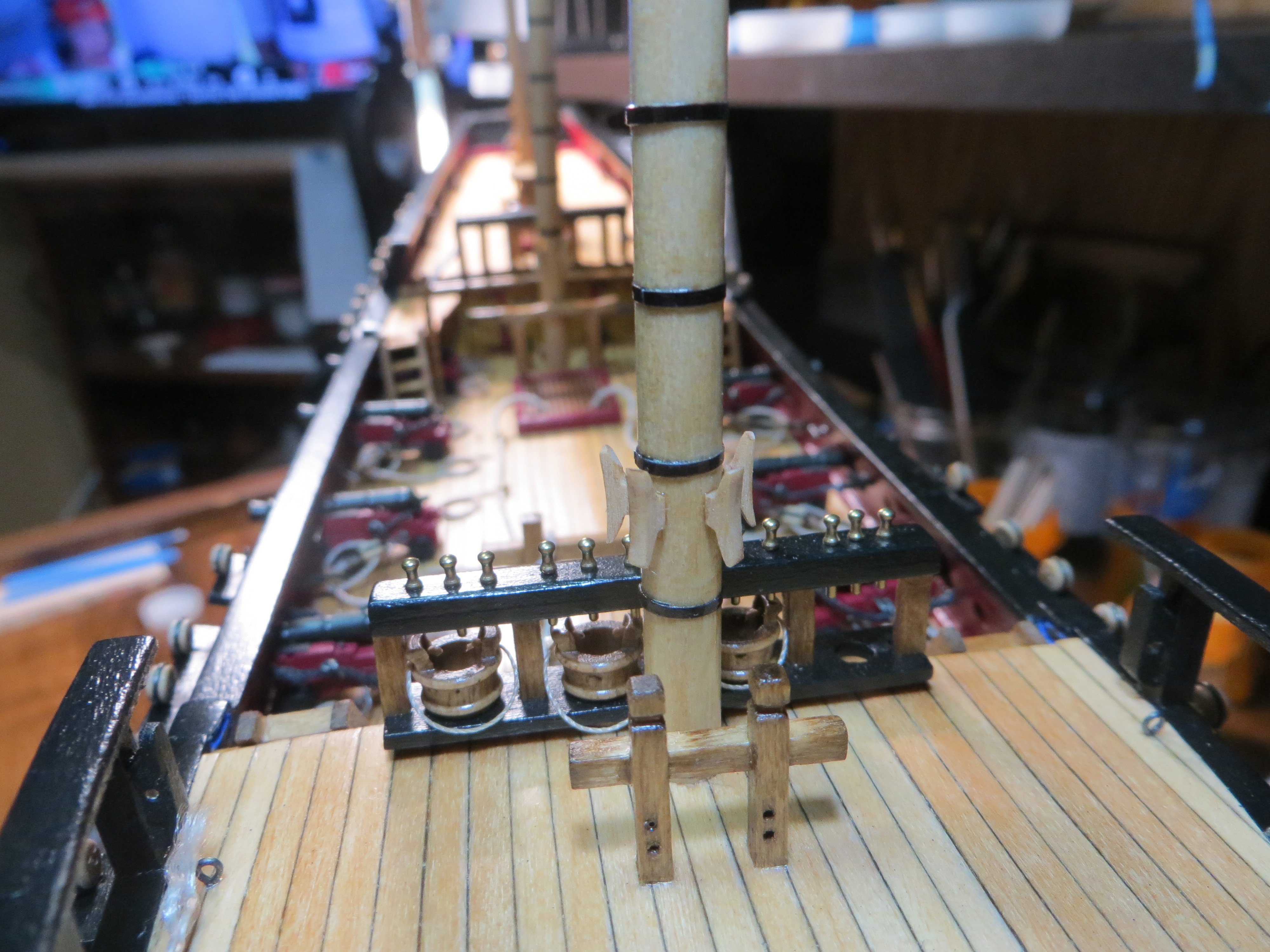
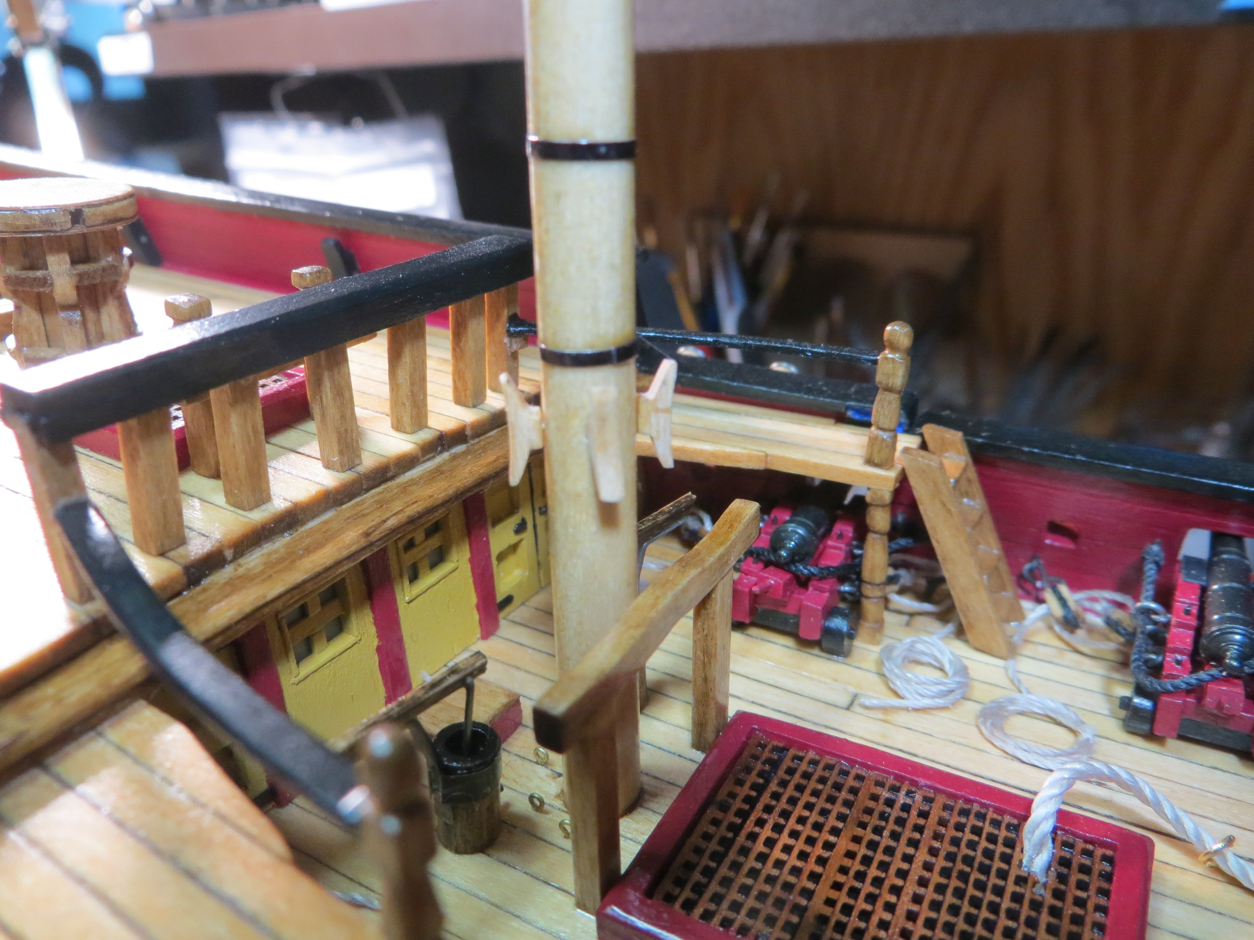
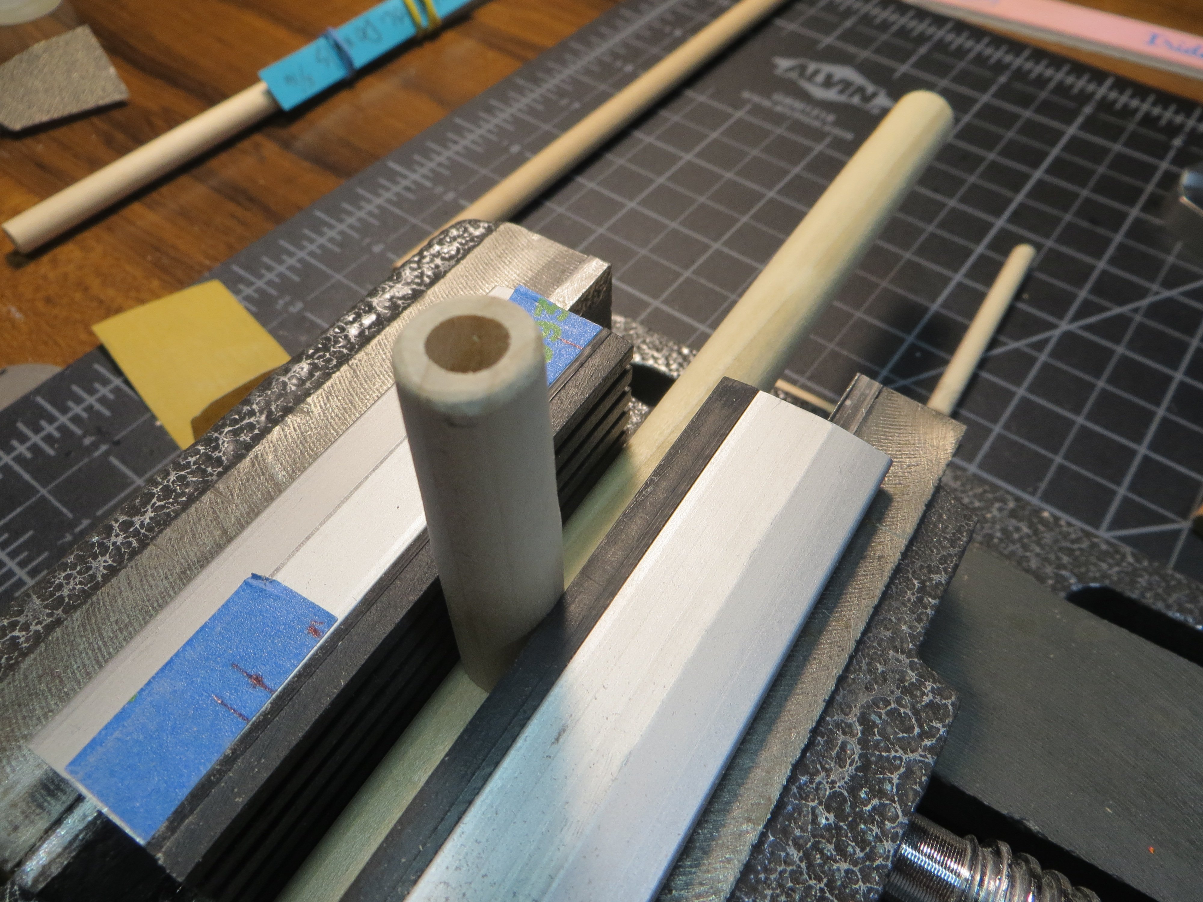
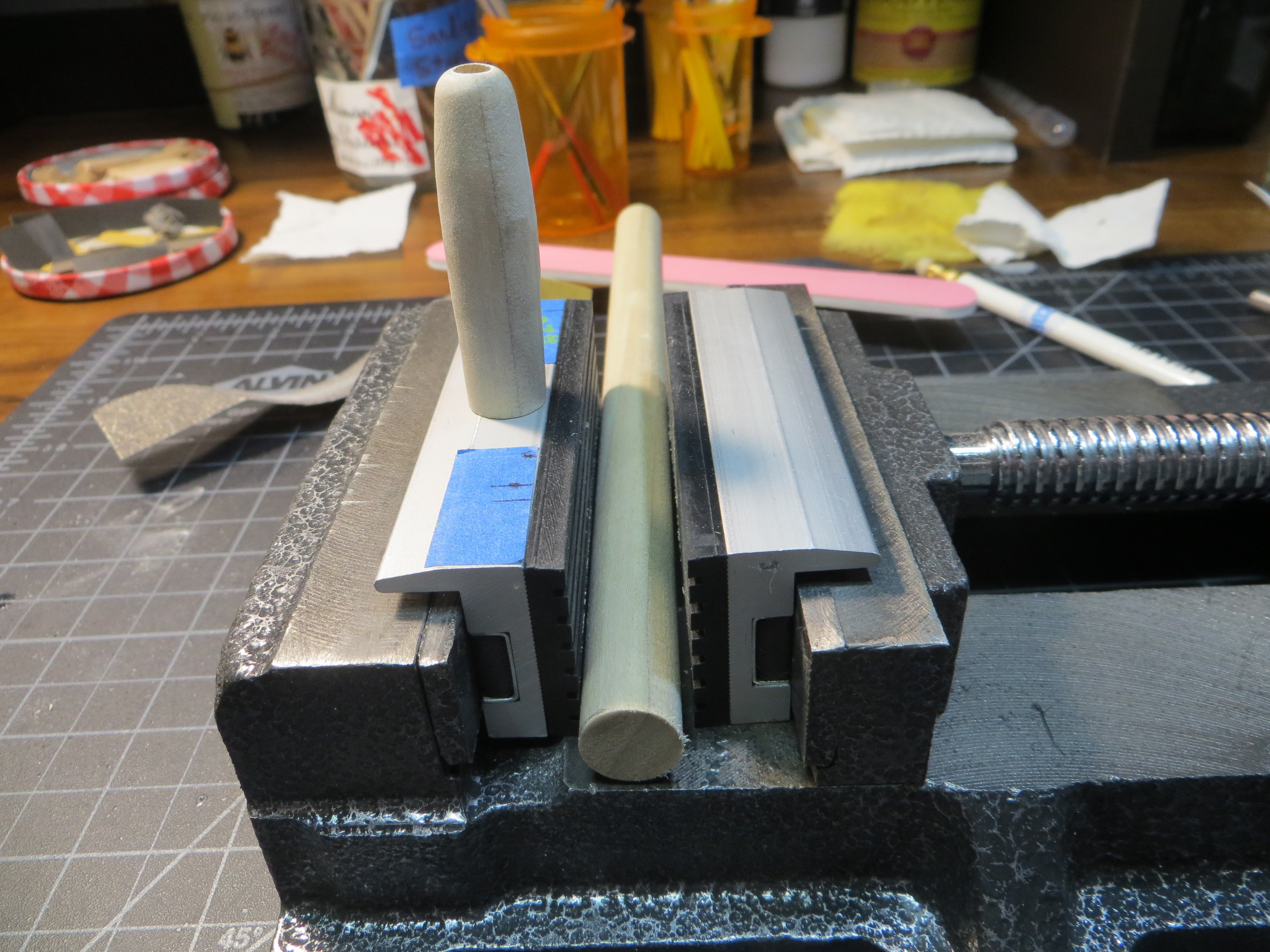
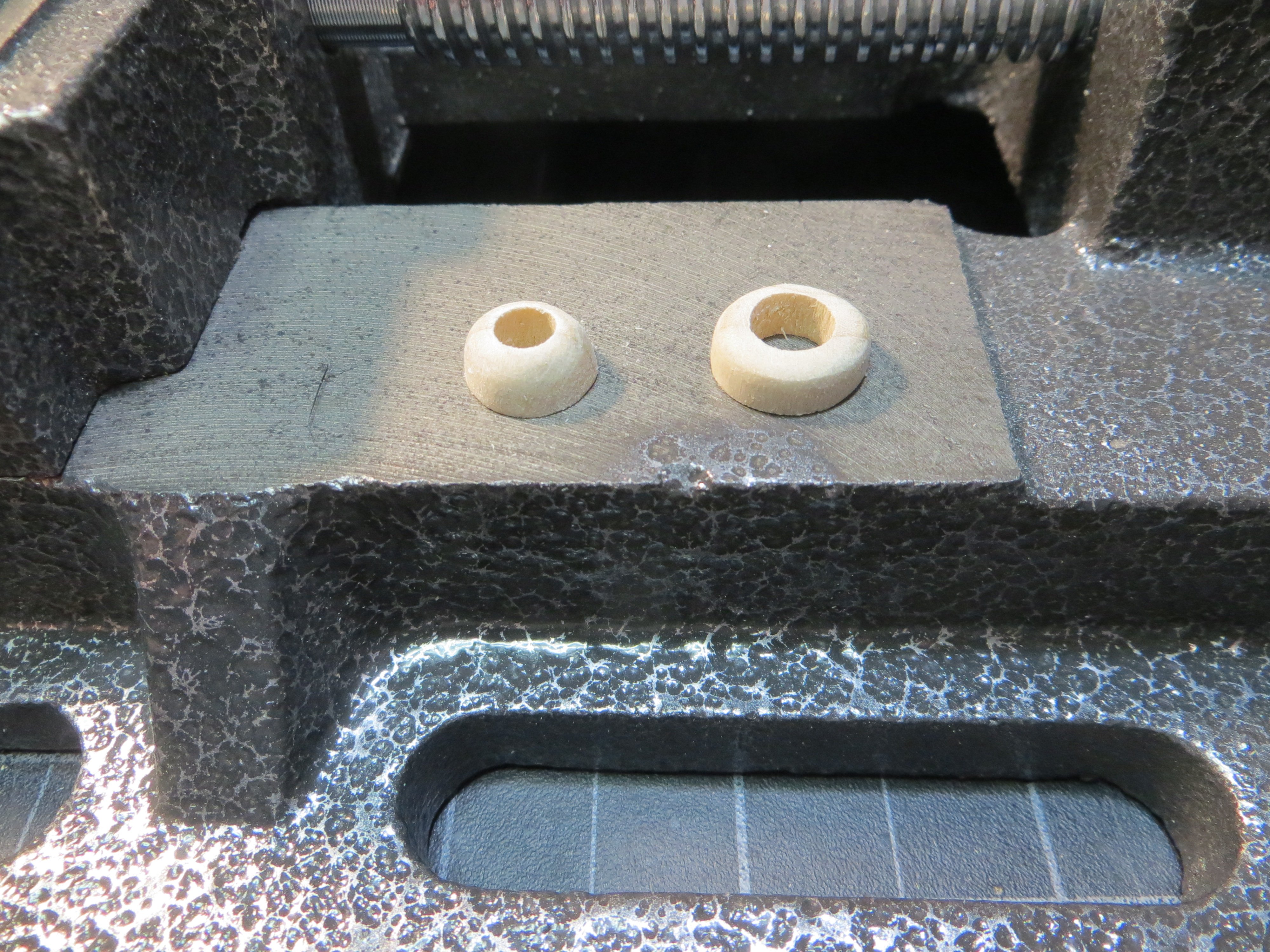
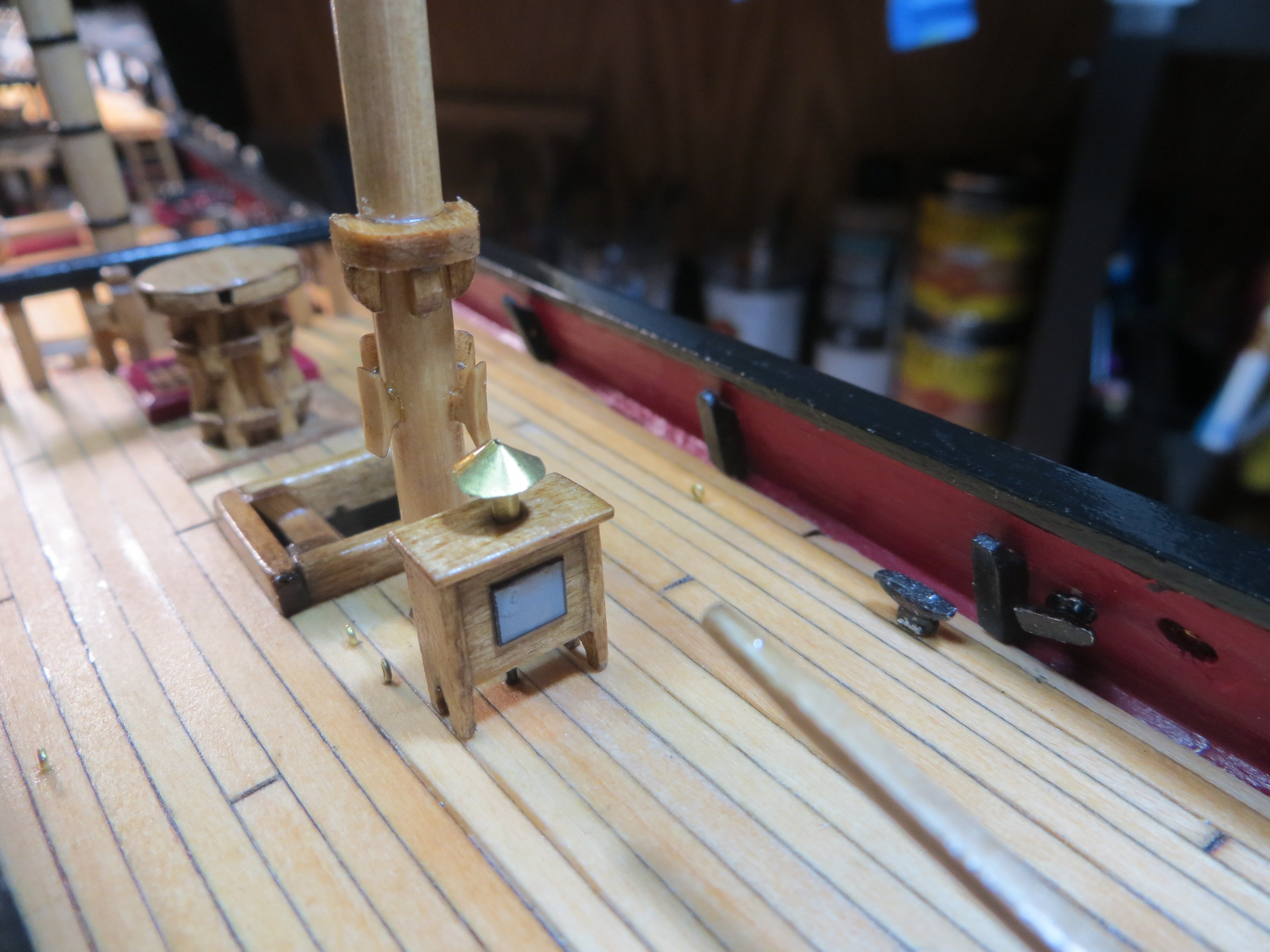
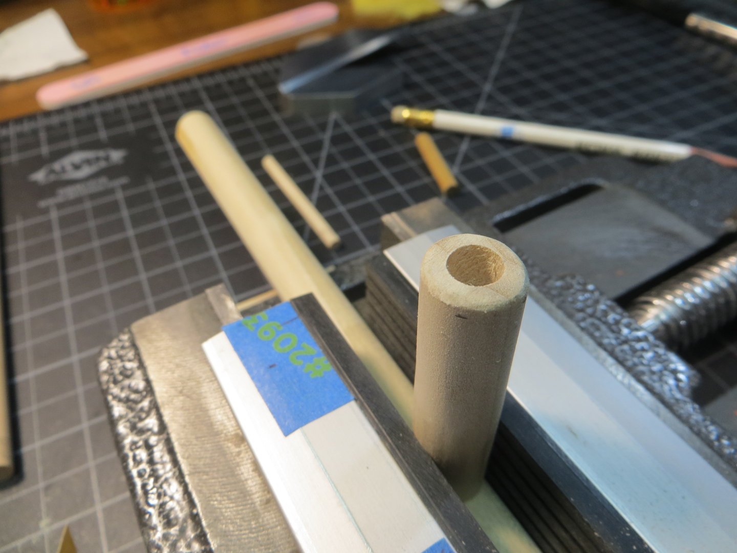
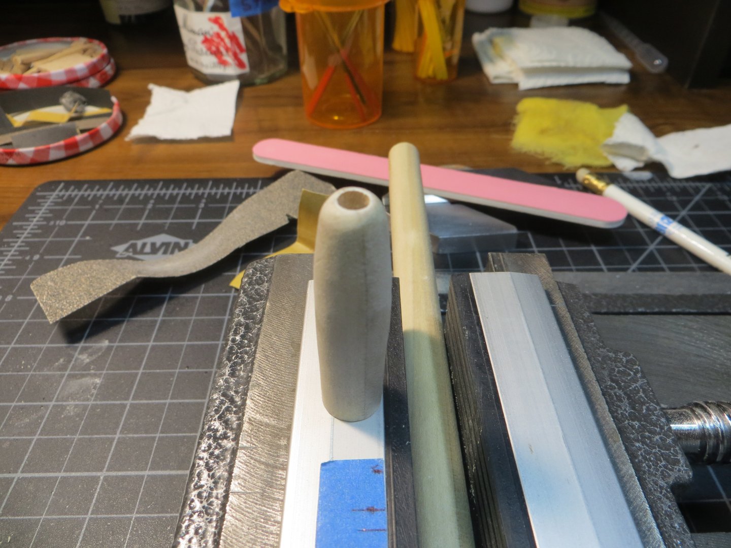
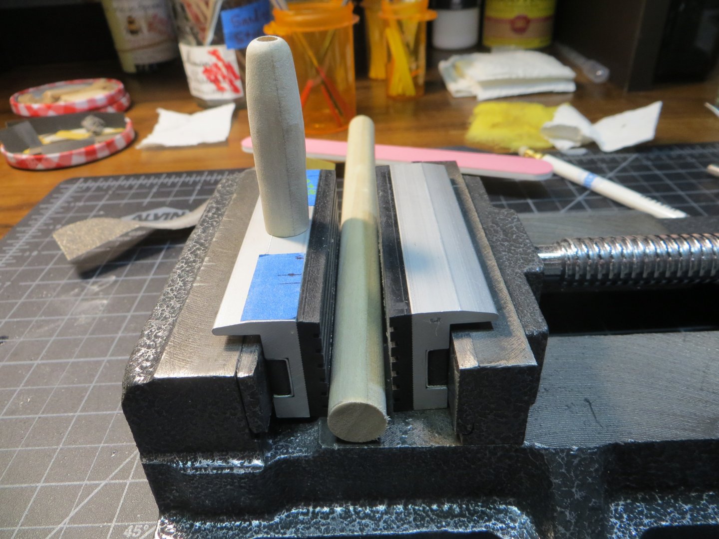
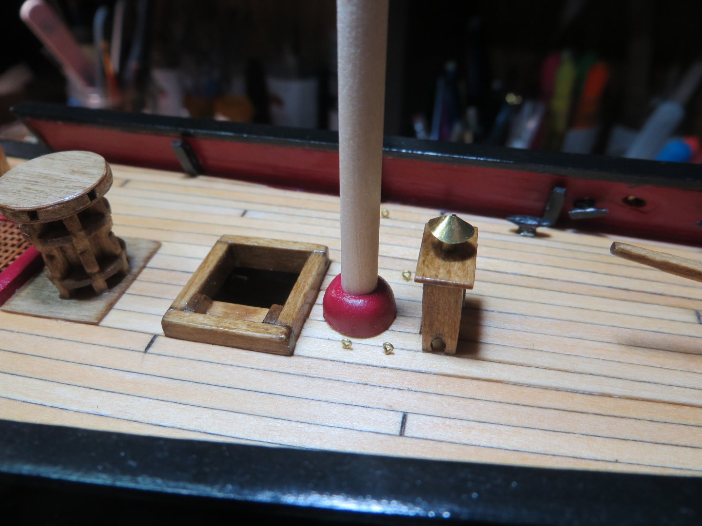
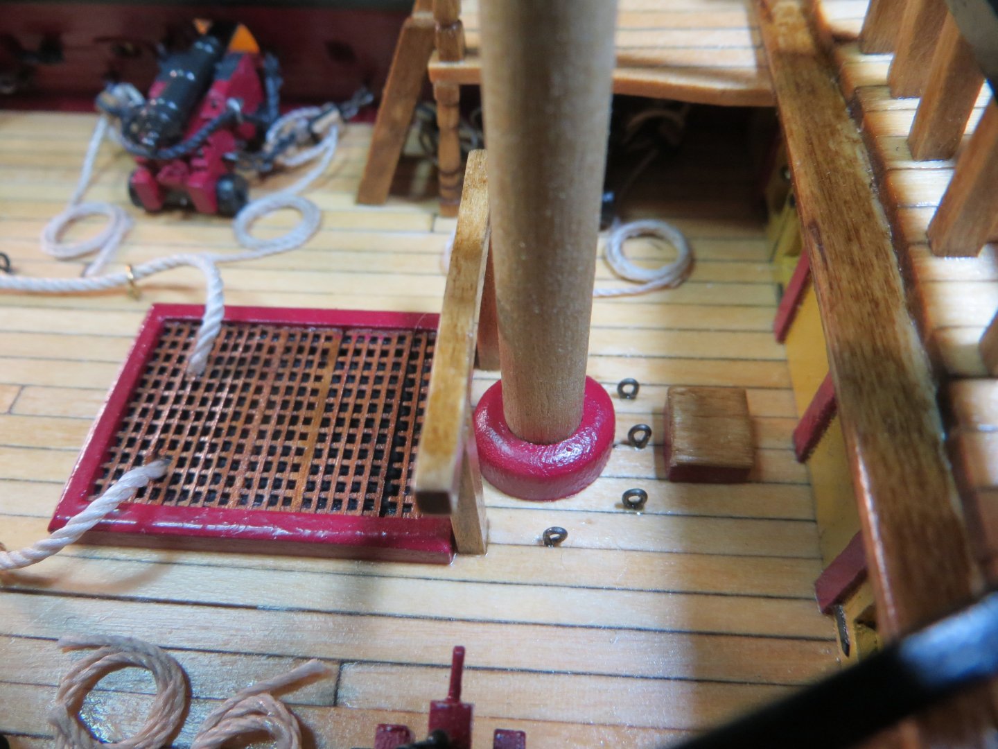
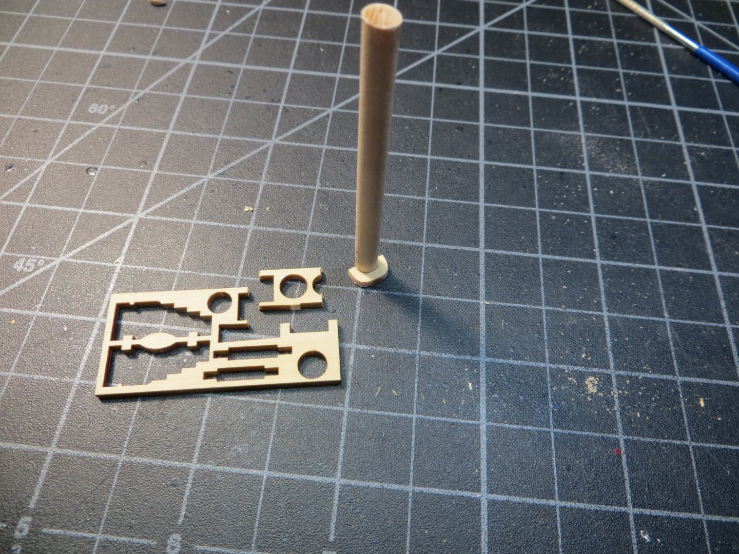
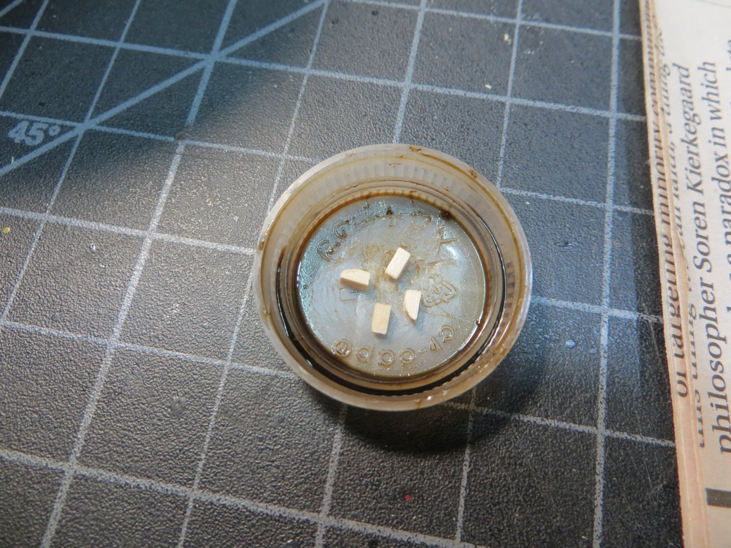
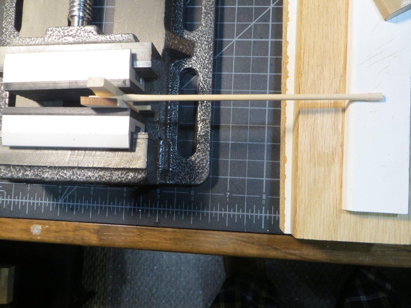
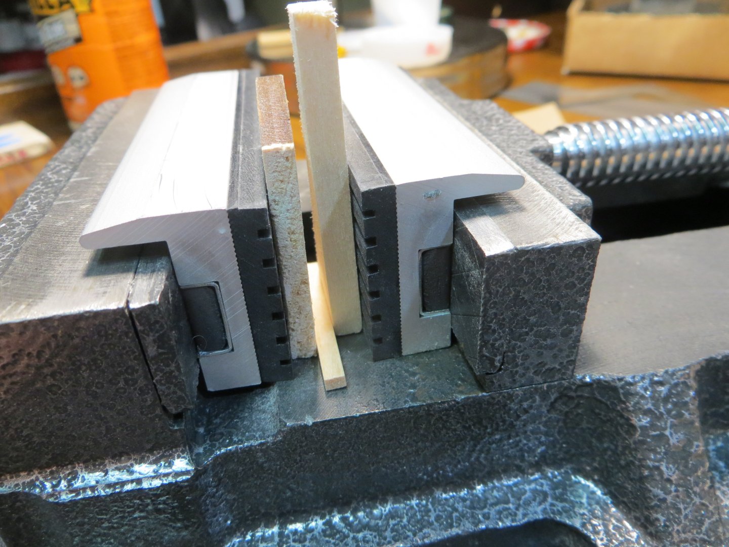
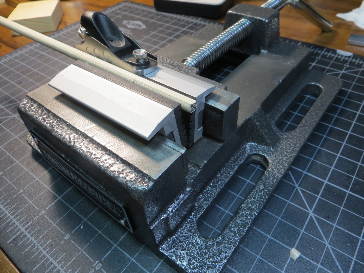
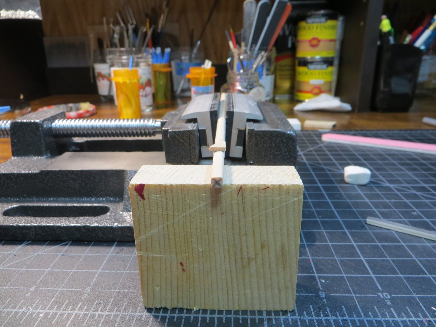
Finish the Mast Cleats & Make the Mast Coats I finished up the Mast Cleats on the Fore & Main masts. I used the larger 7mm size cleats that I got from Syren Ship Model Co. I made them the same way as on the Mizzen mast as covered in my last post. Below are pics of both masts with their new cleats. Mast Coats All 3 masts have a covering around the mast where it inserts into the deck. On the ship this is made from canvas. Model Shipways provides laser cut wood circles to simulate this. On Bluenose I used a method I learned from other builders. I made the mast coats from dowels. On the fore & main masts I used a ½” wide dowel and drilled out the center using my drill press with a ¼” bit. The mizzen is smaller, but I still used the ½” dowel and sanded the outside circumference down to reduce the size. The tops are all rounded off. Here is the dowel in the vise after the center has been drilled out in the drill press. After rounding off the top, I cut the required slice from the dowel. I drilled down deep enough so I can get 2 slices off. For the mizzen mast I flipped the dowel over and made a 3/16” hole. I also sanded down the outer edge They were painted with the same red paint used on the cannons, bulwarks and grates. Below they are shown dry fitted for now on the main & mizzen. The mast coat for the foremast sits on the main deck under the focsl. I only want to finagle that one on one time! But it is also ready to go. I had to relocate the eyebolts around the main mast. They were too close for the mast coat to fit. I decided to put in some heavier annealed steel ones to make them easier to rig later. I also cut down the height of my bilge pumps. I felt like they looked out of scale, even though I took the measurements off the plans. It was a pain to do, but I wasn’t happy with how they looked! That’s all for now! Ed


-
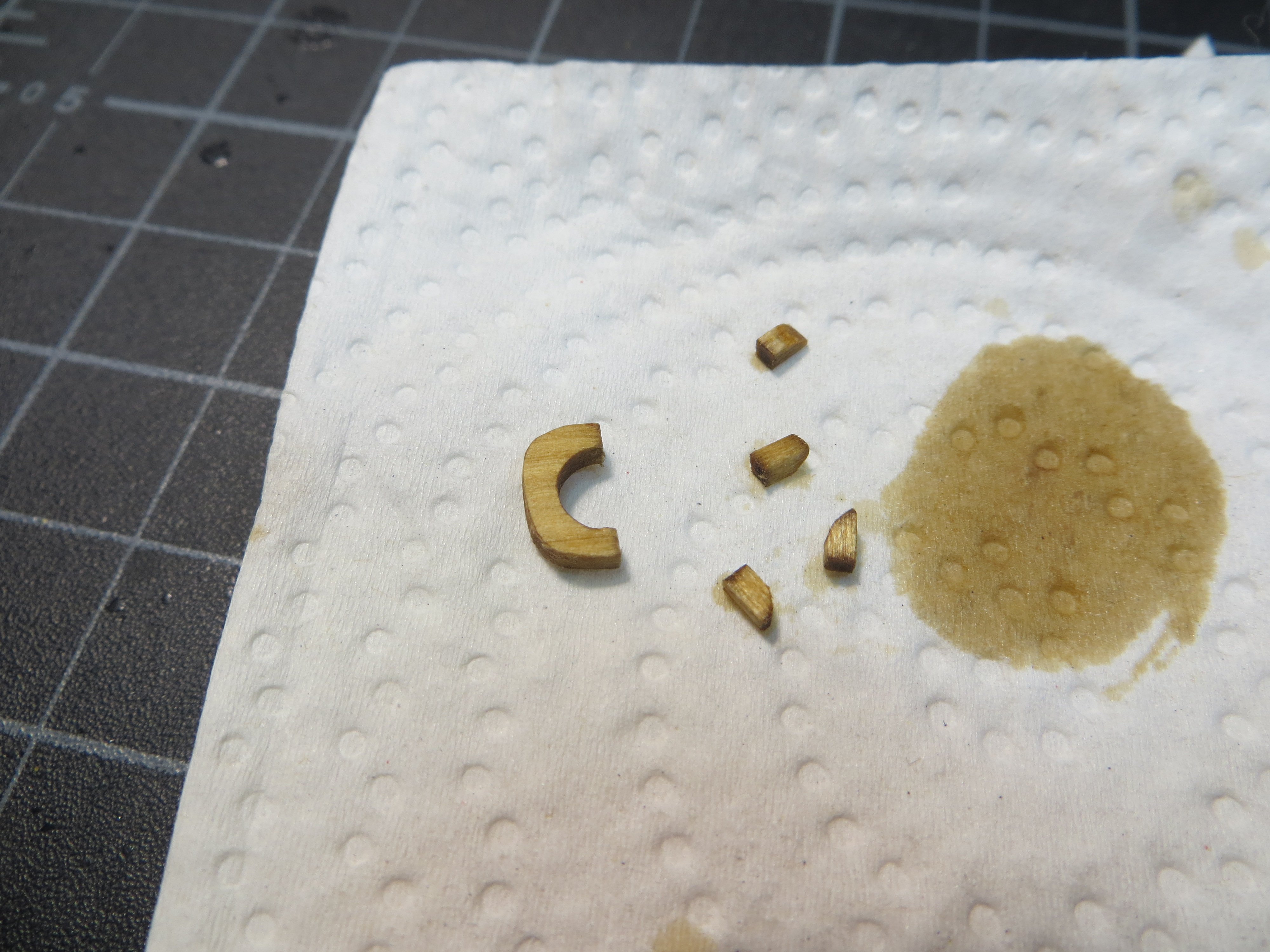
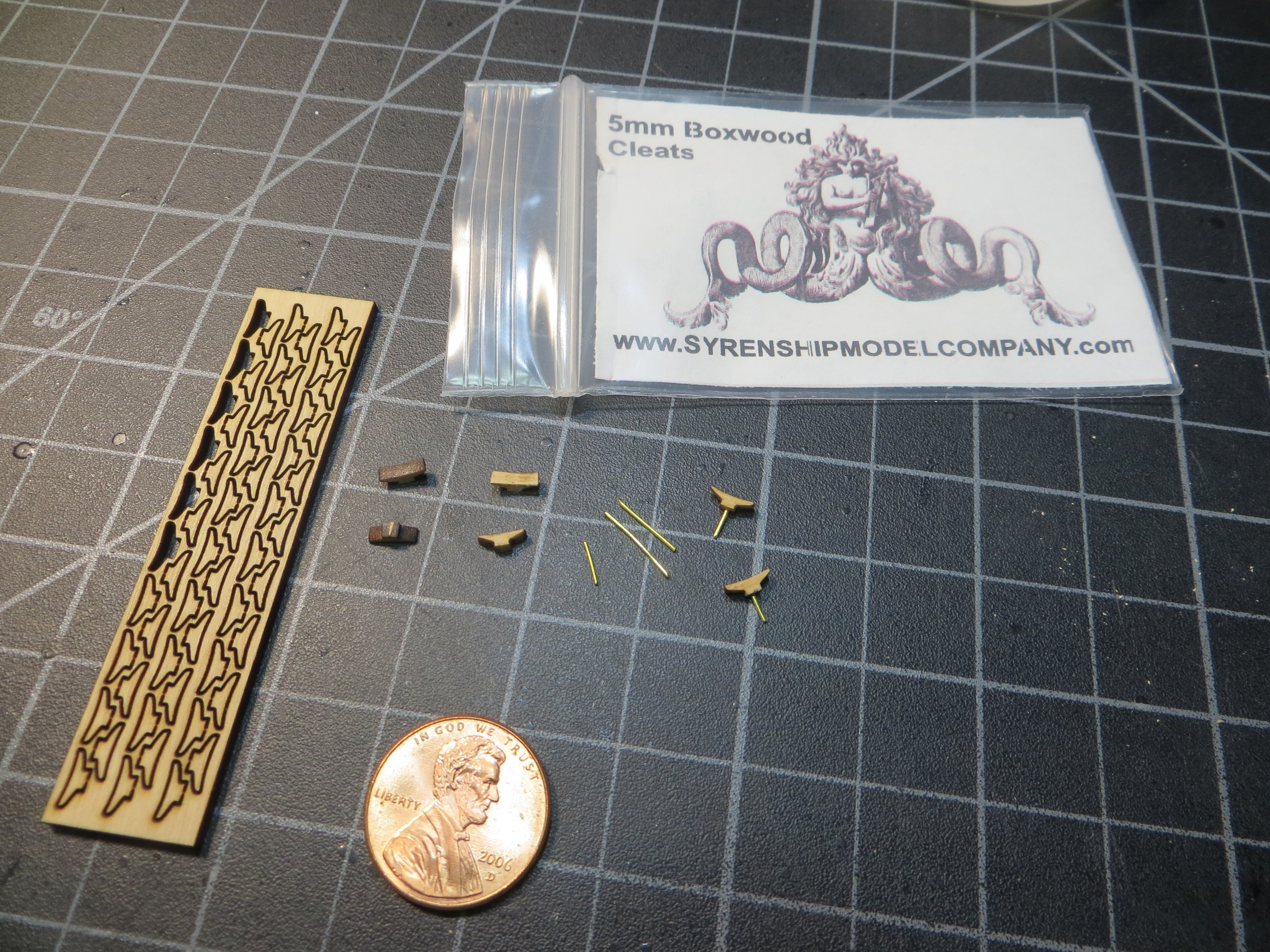
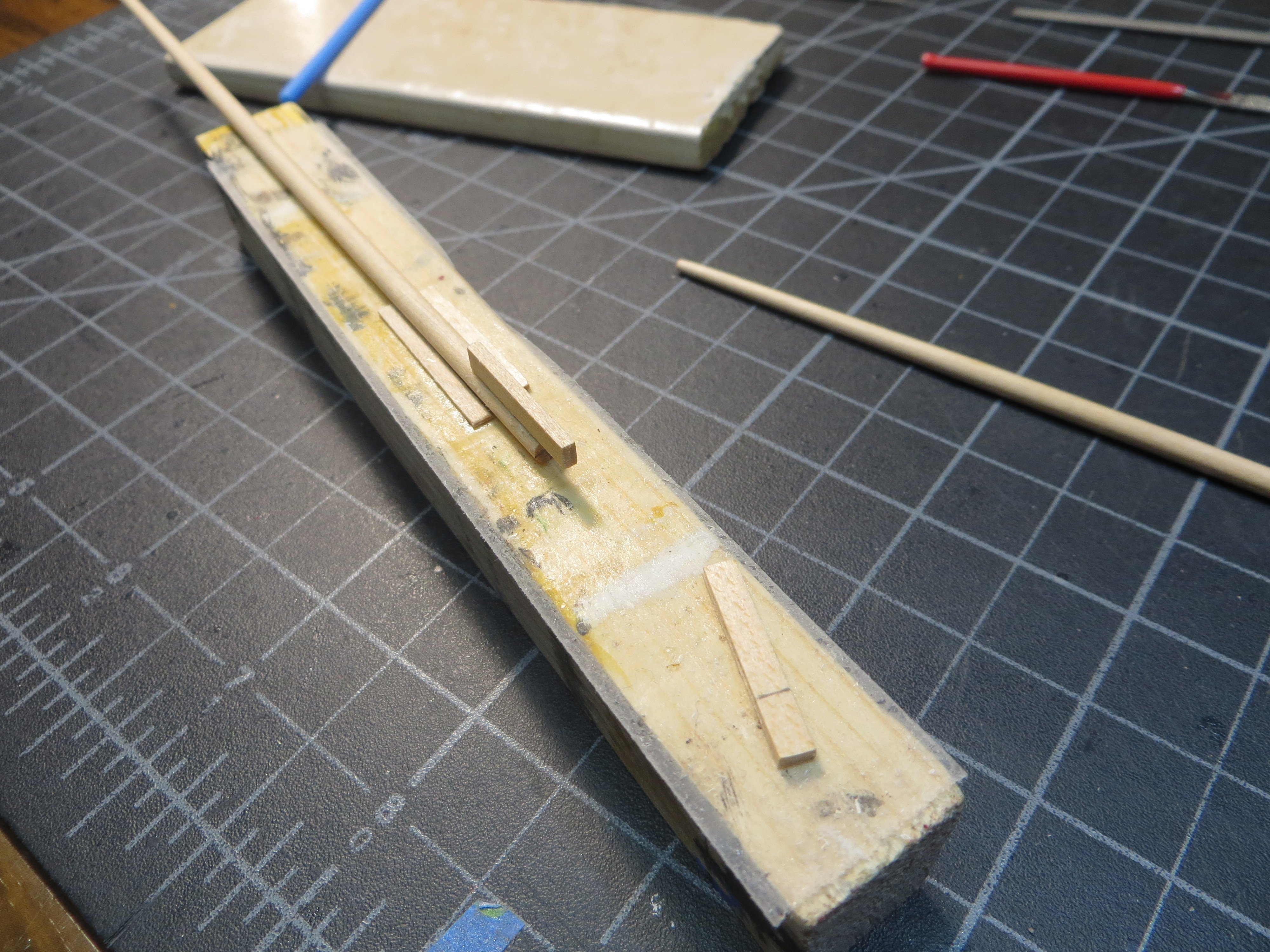
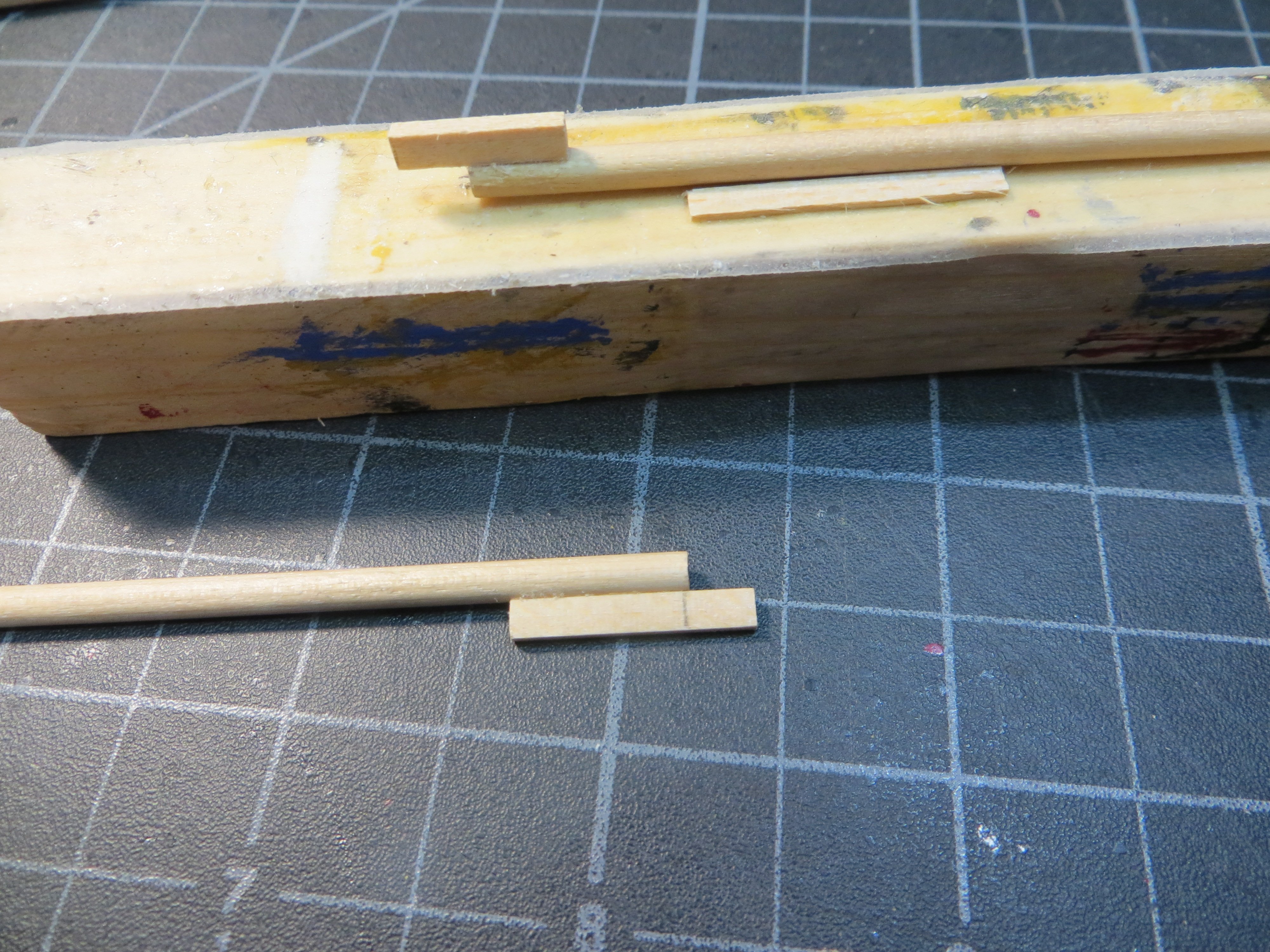
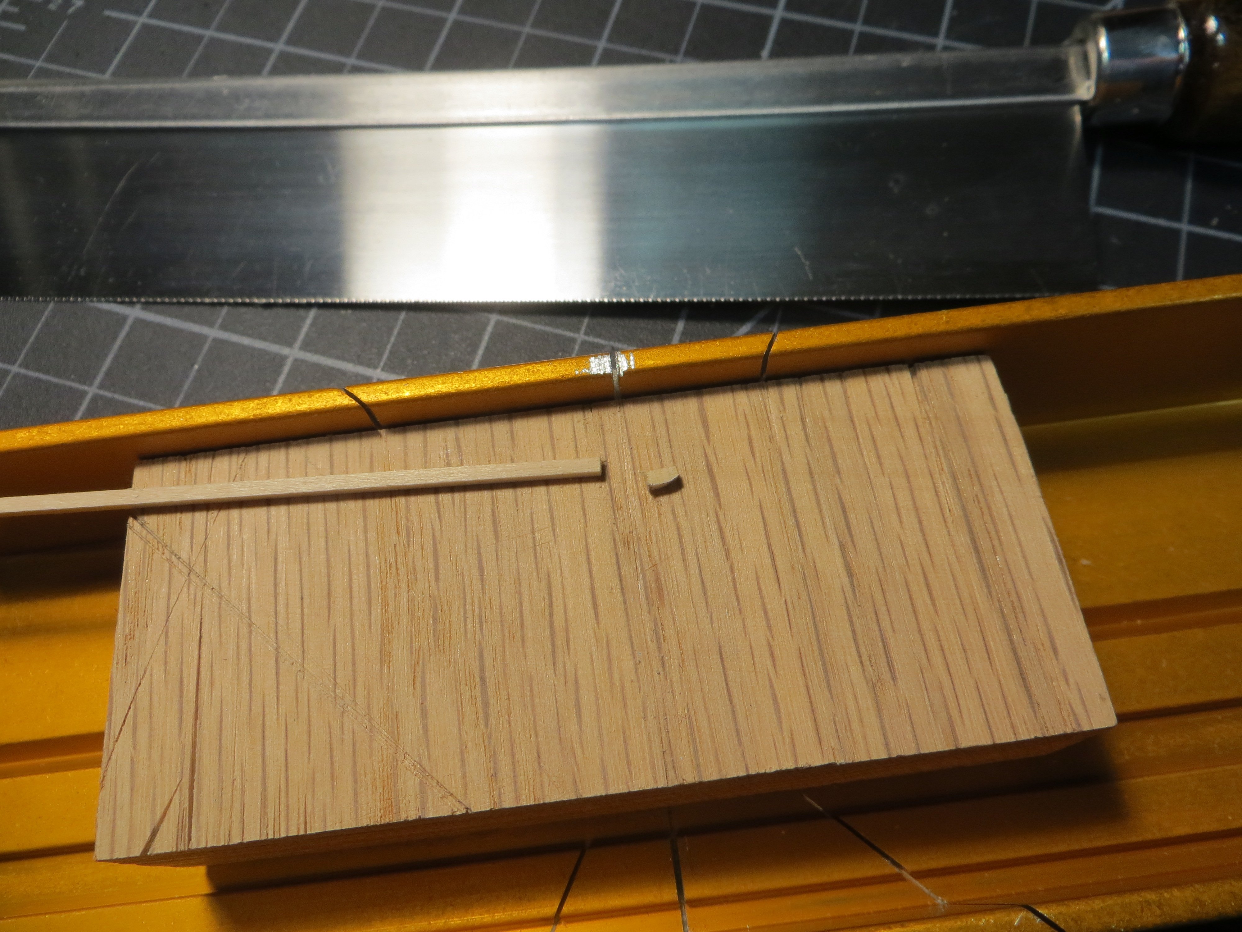
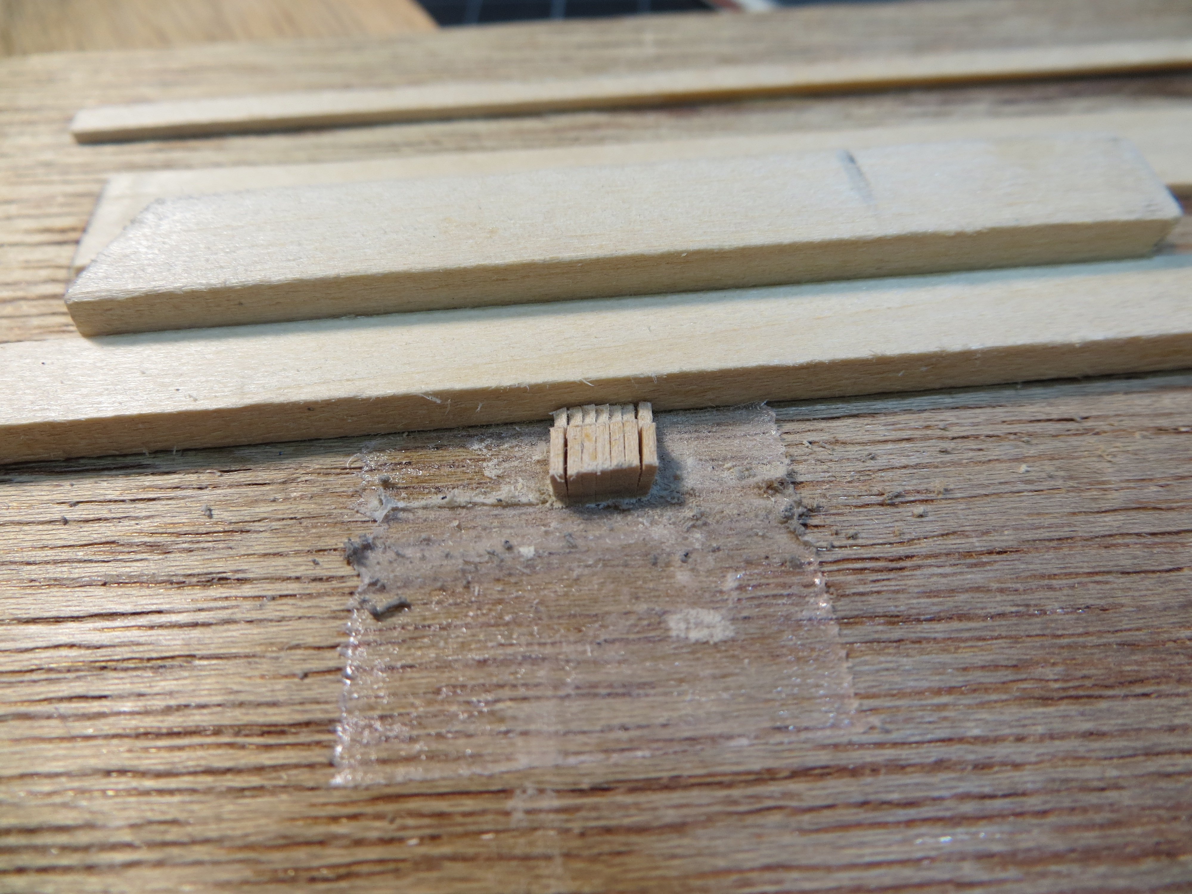
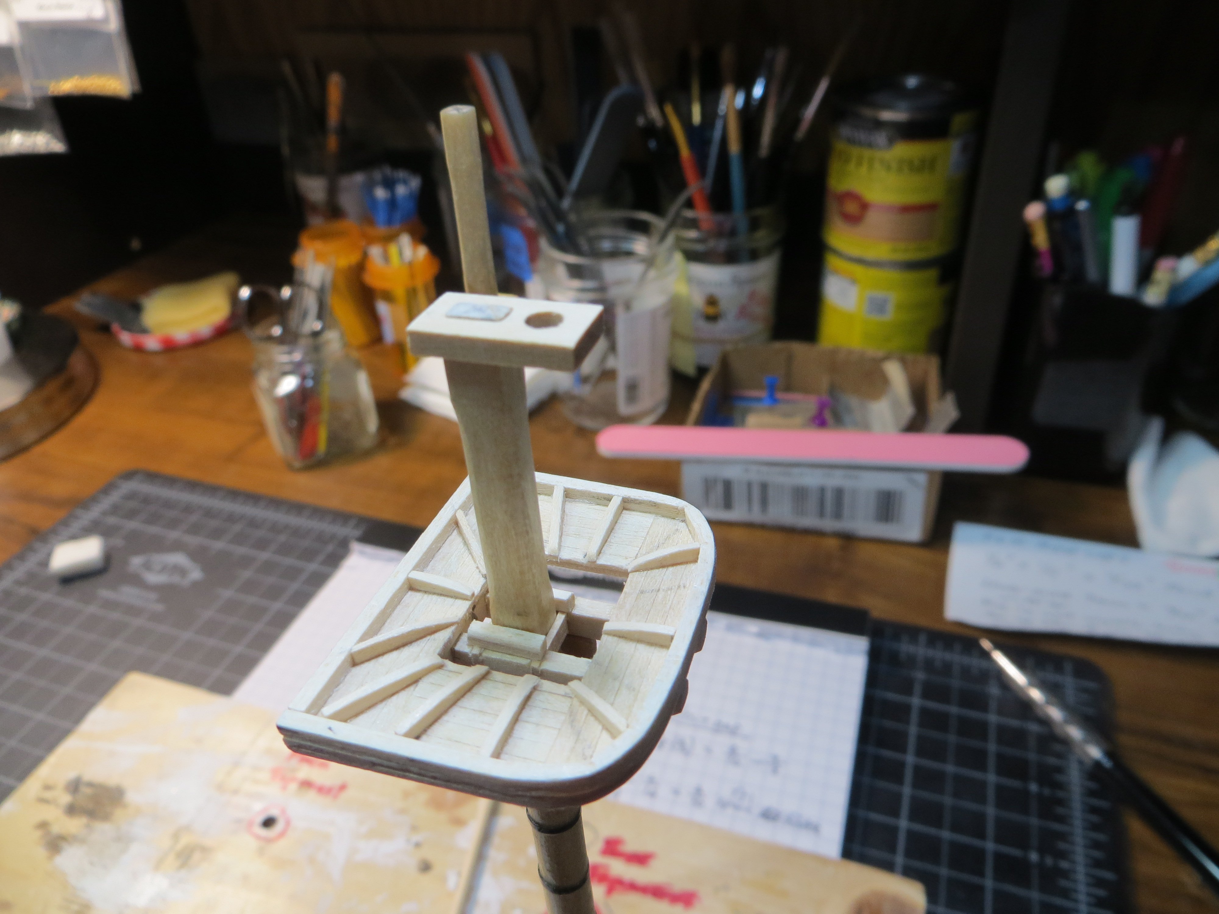
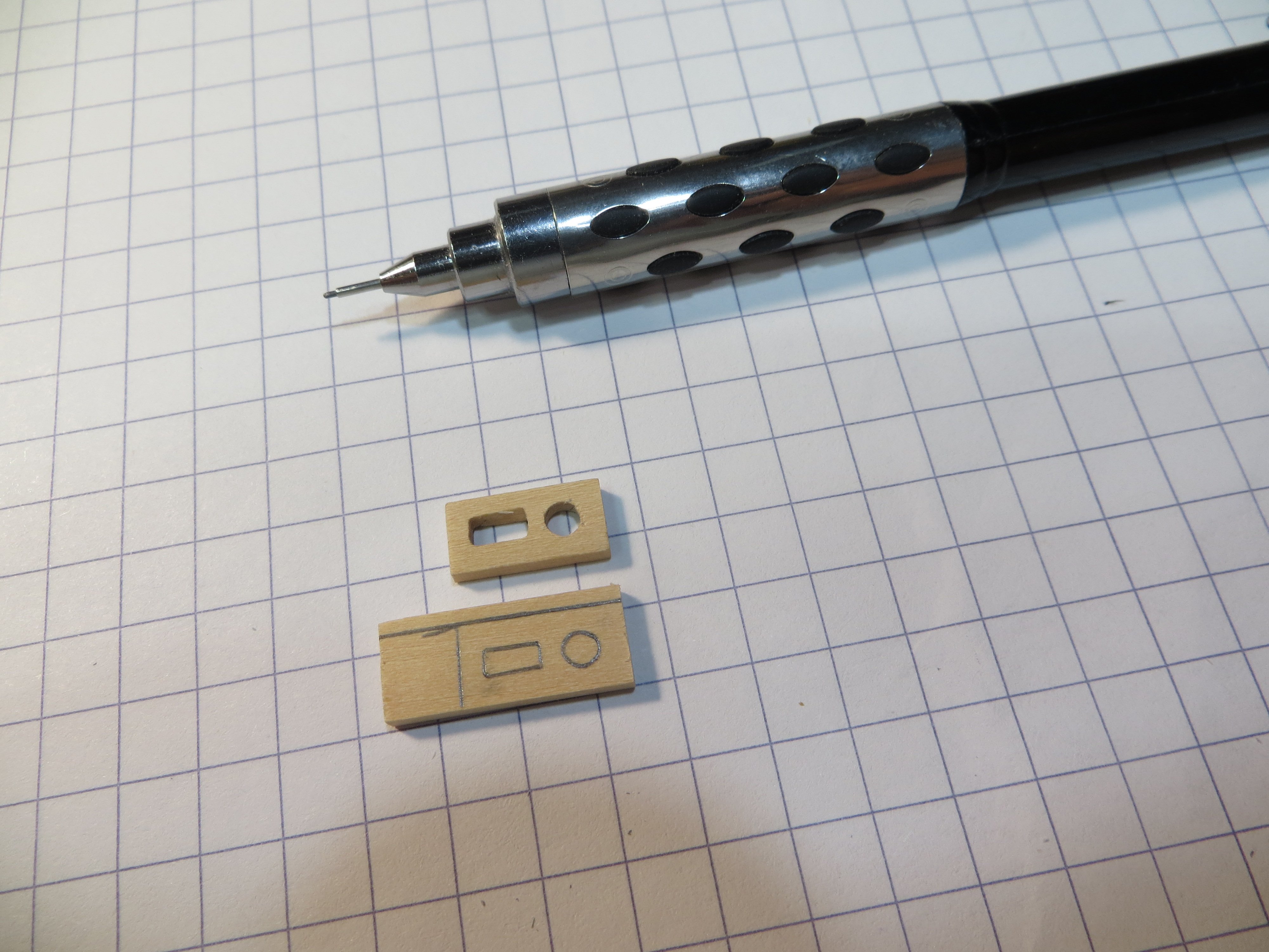
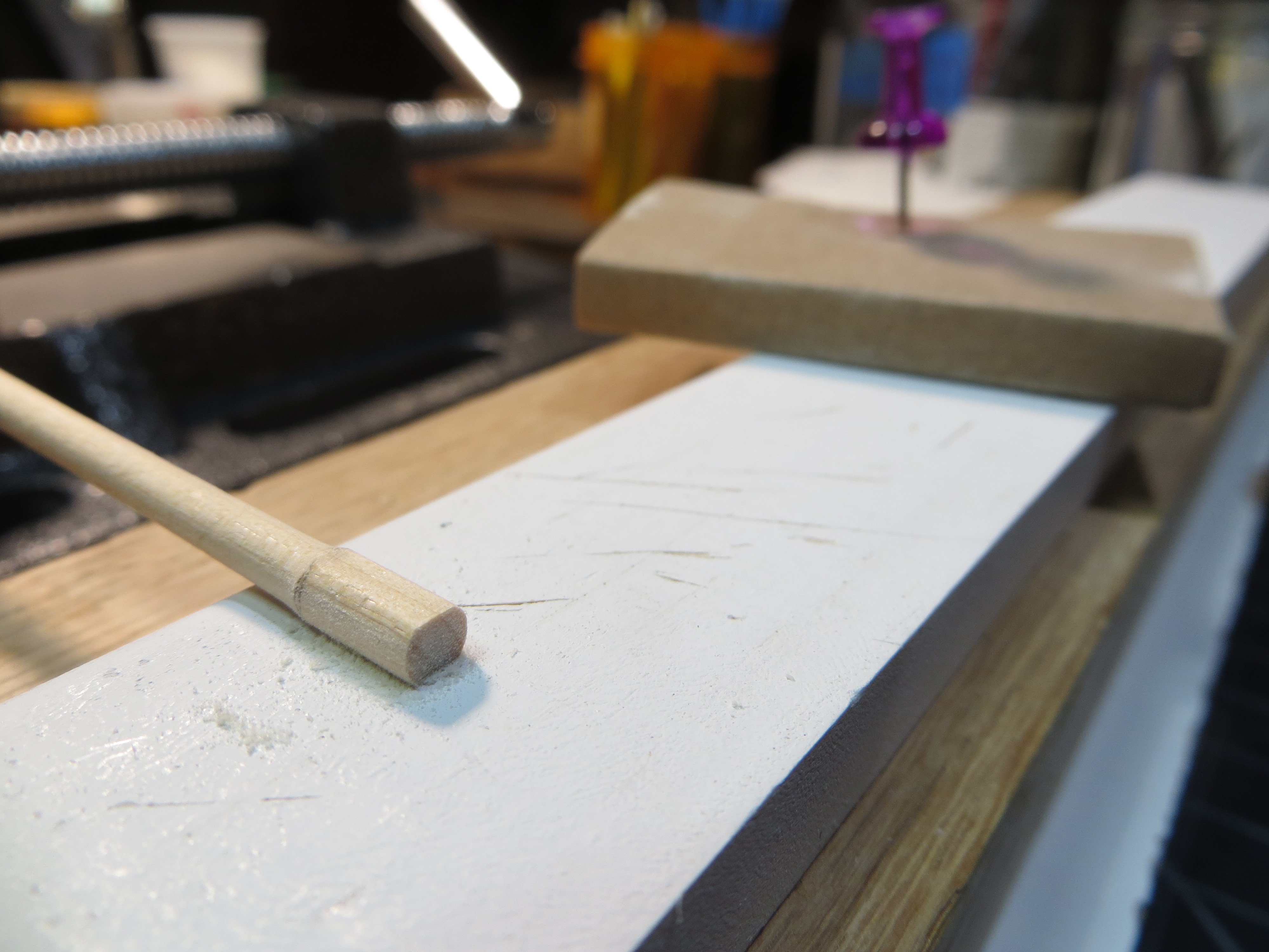
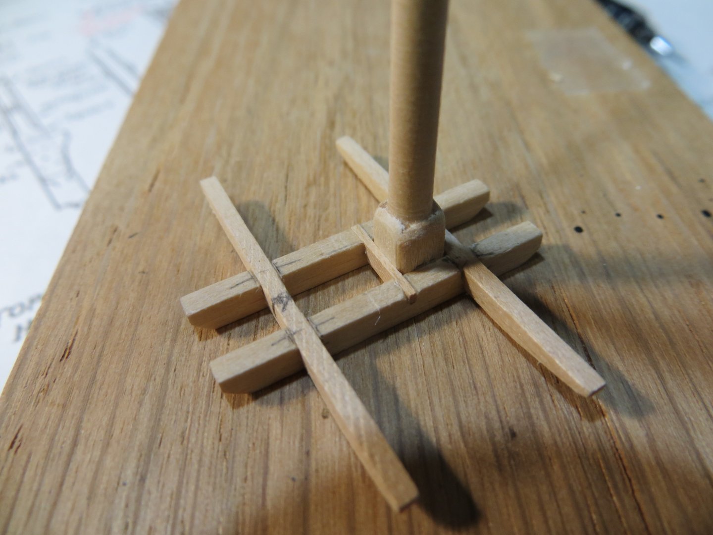
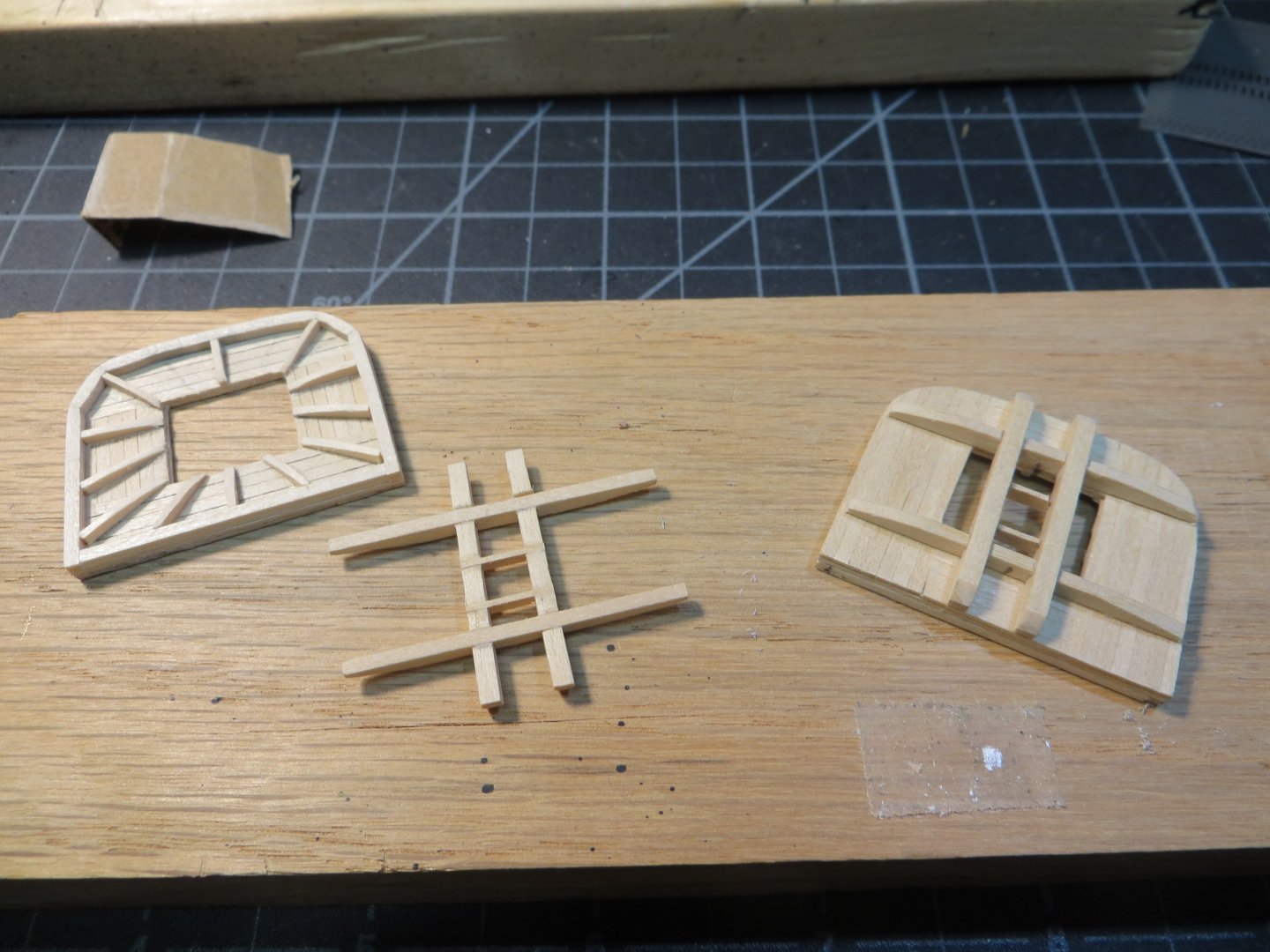
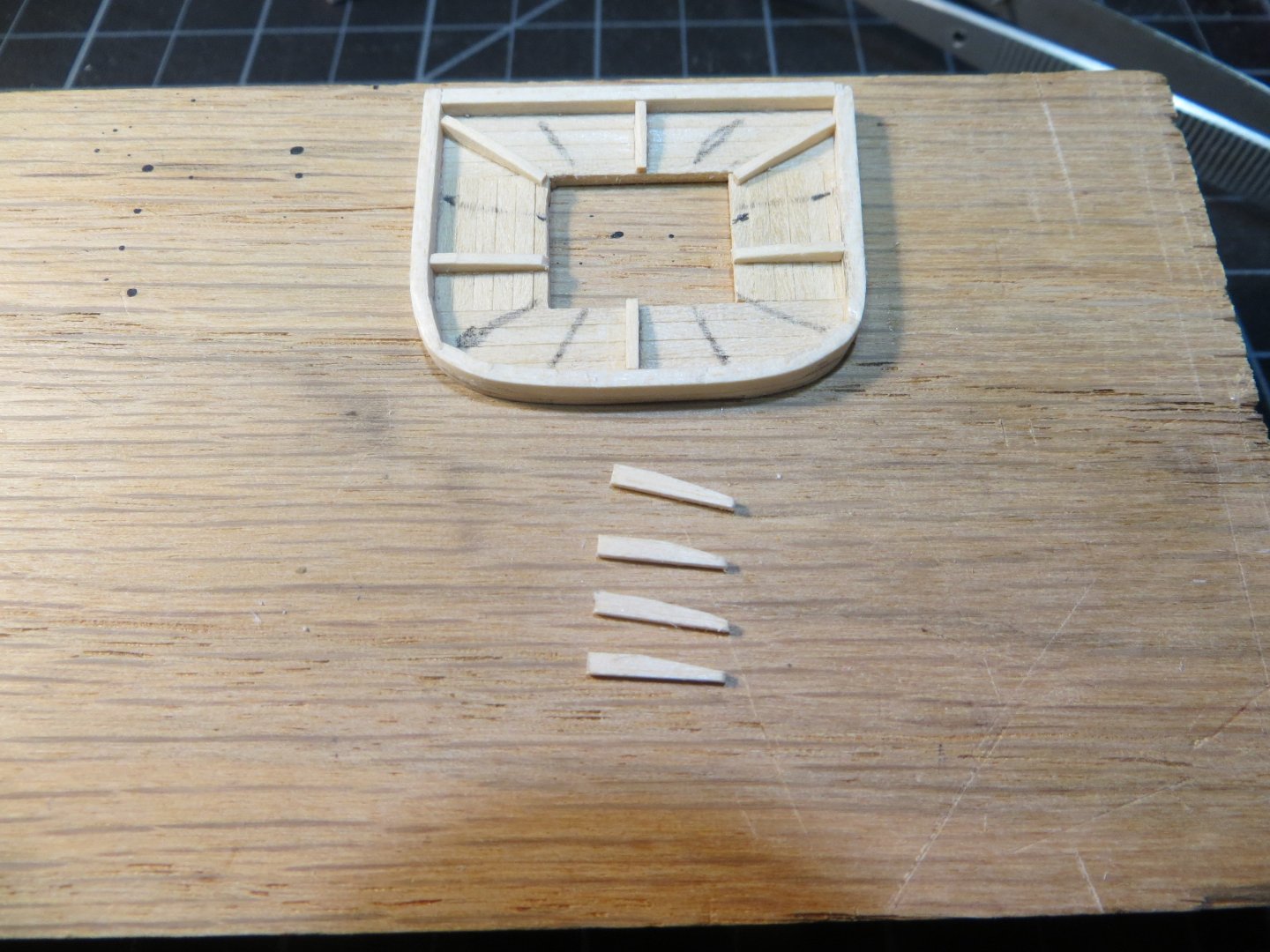
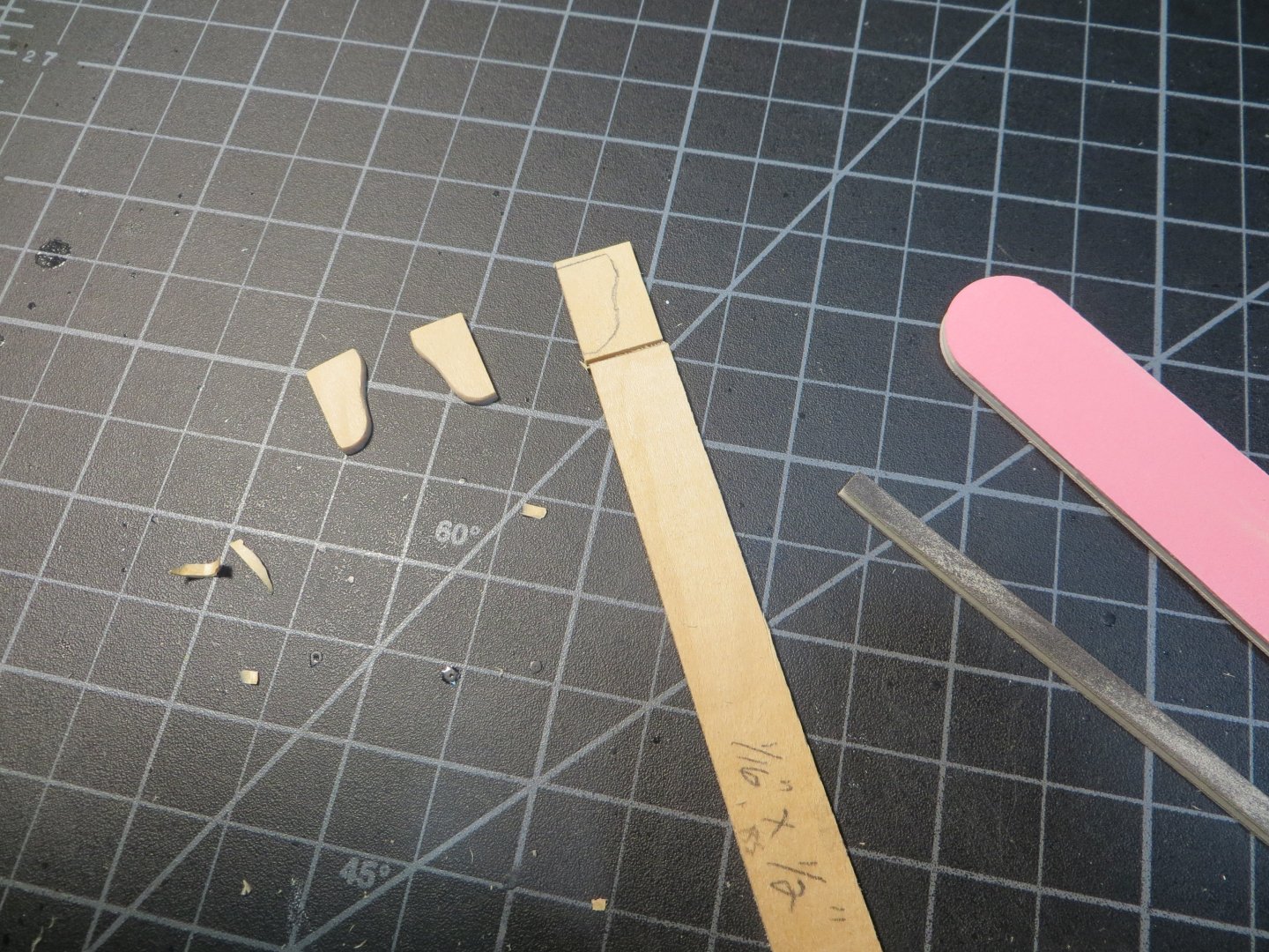
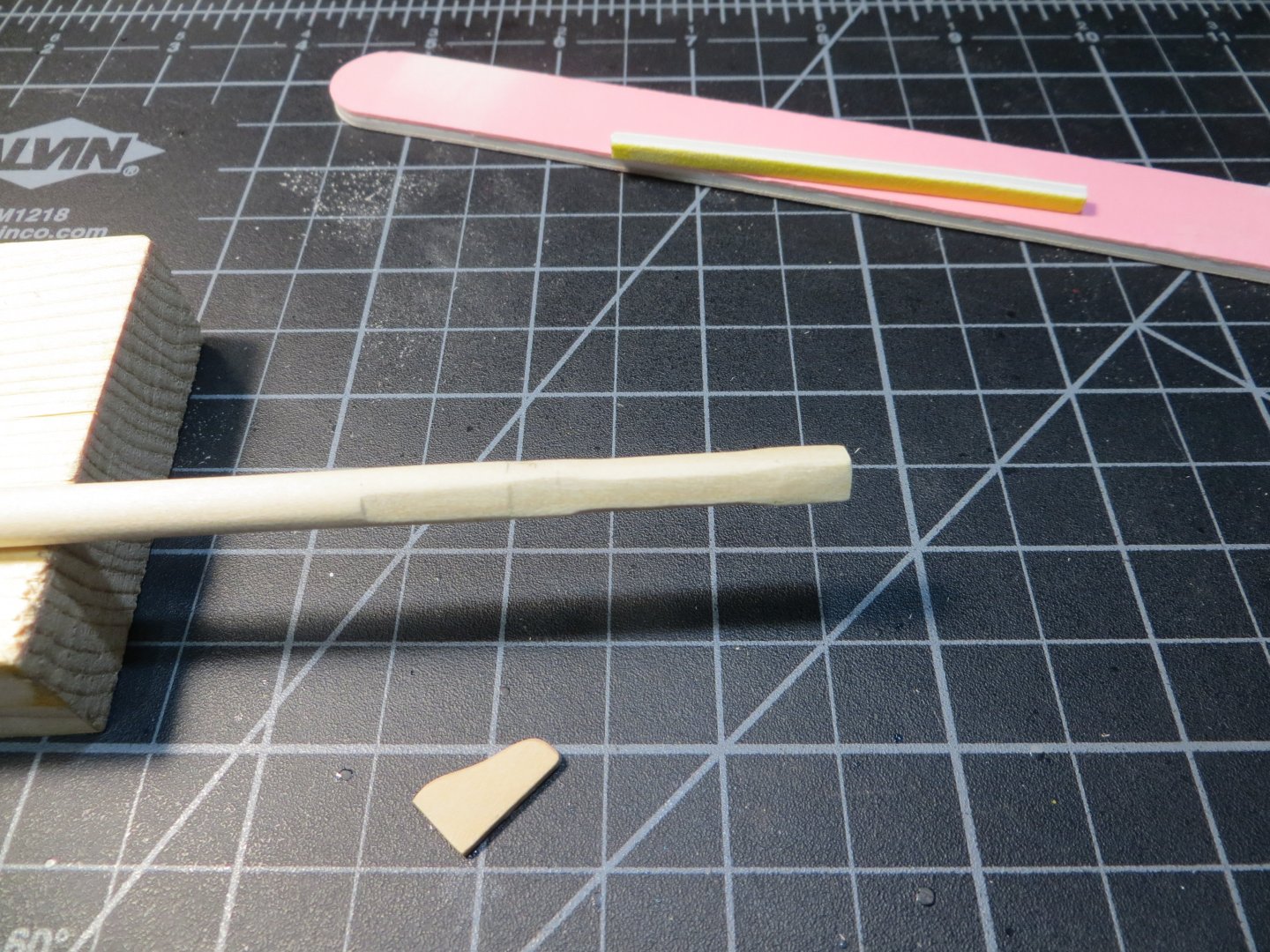
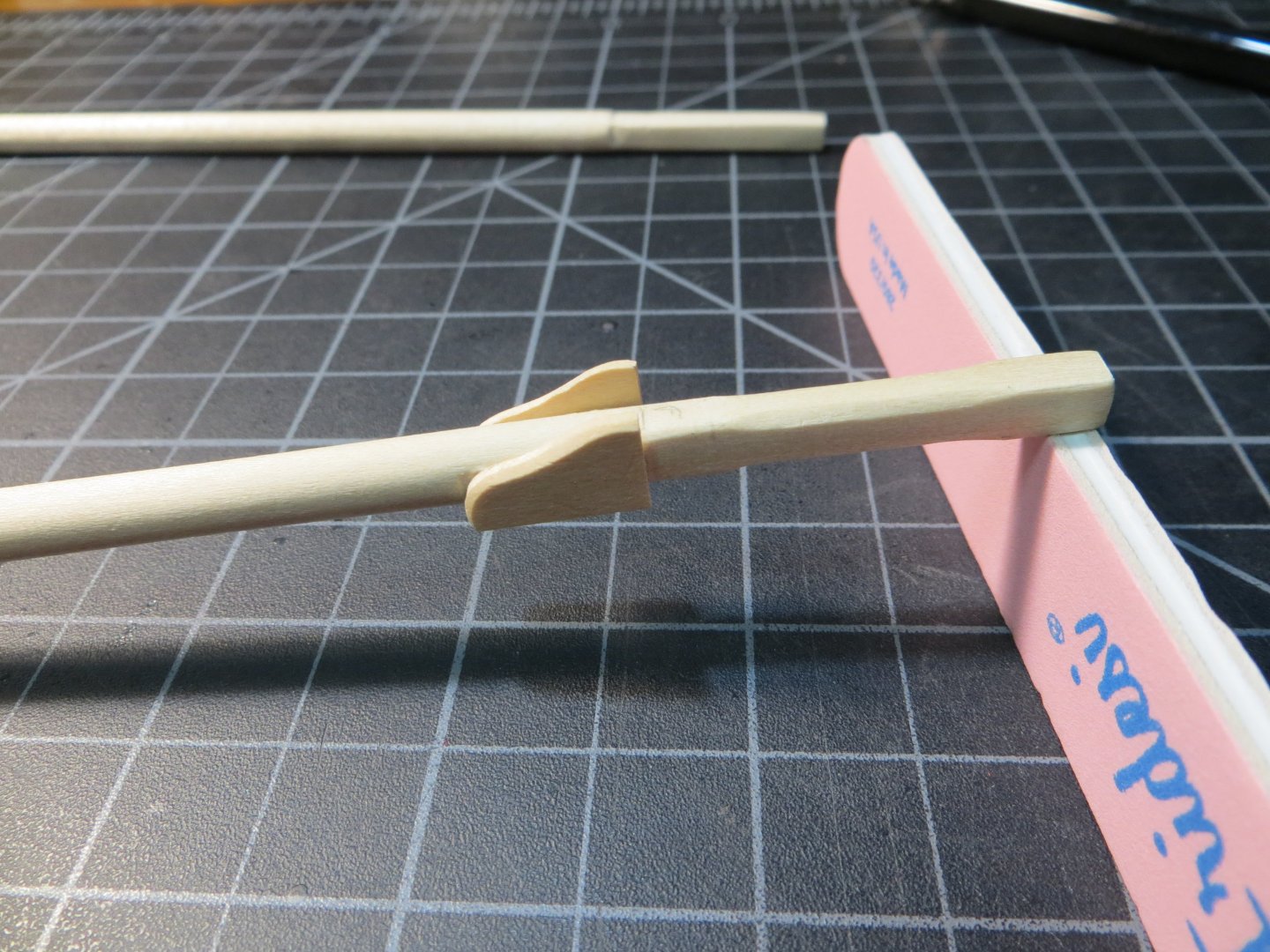
MISCELLANEOUS STEPS TO COMPLETE BEFORE STARTING THE RIGGING There are still a number of steps that I need to take care of before moving on to rigging. I will cover these as I complete them. Below are the first two pieces installed on the Mizzen Mast. Spanker Boom Rest on the Mizzen Mast The Spanker Boom rests on top of a half circle disk that is glued to the aft side of the mast. The mizzen mast is 3/16” in diameter. The disk should be 1/16” wider than that. 1. So, for starters, I selected a 1/16” thick piece of stripwood wide enough to cover the diameter of the mast plus an extra 1/16” to hold up the boom by its jaws. I tried using a 1/16” x ½” kit strip. Turns out this was too thin and it just fell apart when I tried to cut the half circle off the end of the strip! 2. I decided I needed a harder stock then boxwood and a little thicker. I searched through my scrap wood pile and found that the leftovers from the Syren cannons had a 3/16” hole ready-made from the front trucks. This wood is yellow cedar and also thicker at 5/64”. I trimmed off the piece I needed from the rest and made a concentric circle around the hole that was 1/16” wider. This worked quite nicely. 3. File & sand the outside edge to shape the outer circumference. Actually, I only needed a half-circle. 4. Cut the half circle off with the razor saw. I stained the boom rest using Golden Oak to set it apart from the mast. 5. I glued it to the mast using thick CA glue at the height indicated in the MS plans 6. Four tiny wedges are cut from 1/16” x 1/16” stripwood. I sanded them using the shape & method like the chocks on the yardarms. These were stained and then glued underneath. I actually only used 3 of them around the half-circle. Below: Completed Boom Rest test fit against a scrap piece of 3/16” dowel. Next to it is the yellow cedar scrap wood that I used. The support chocks that go under the boom rest are ready to stain All the pieces after staining with Minwax Golden Oak Mast Cleats I purchased a pack each of 5mm & 7mm wood cleats from Syren Ship Model Company. The Britannia cast metal cleats in the kit are 6.5mm. All 3 masts are supposed to have six cleats each. I determined that the smaller 5mm fit best on the smaller mizzen mast. As I attached them, I decided to go with 4 cleats. A couple of them are used for sheets, which I do not need since I’m not adding sails. Six was going to be too crowded. The steps were as follows. 1. Cut the cleats off the sheet and clean the laser char off. These are so tiny, they are difficult to hold and sand at the same time! 2. Insert a pin in the bottom to secure them, since they will have rigging lines tied to them. I used the cut-off ends from eyebolts for the pins. These are a mere 3/128” in diameter. 3. Drill holes in the mast and glue the cleat pins in the holes. I dip the pin in Gap Fill CA glue The 5mm cleats from Syren. Left to right: The sheet of laser cut cleats, pair of cleats with laser char, without the char, the eyebolt cut-offs used for pins and finally the finished assembly Here is a pic of everything glued up on the mast after a coat of poly I still have to set-up the mast cleats on the Fore and Main masts. Next up will be making the Mast Coats, glue down the Catheads & open gunport lids at the bow. I will also pre-rig the tie-down for the Longboat and the Anchors. But I won’t install these yet. I think they will be in the way and in danger of getting damaged while rigging. I will decide later when to add these. At some point the rigging will get in the way of setting up the longboat! Happy New Year Guys! Ed


-
I did not get any replies to my question in the above post. Perhaps none of you have used these on your models. So I emailed Chuck Passaro at Syren Ship Model Co. Just FYI, in case some of you may want to purchase these parts in the future, here was his response. "Thimbles are outside diameter. Same is true with CLOSED hearts....measurements are the length. Open hearts are not as long but replicated to be a partner to the closed hearts. So an 8mm closed heart should always be paired with an 8mm open heart even though it isn't 8mm long. The width will be identical however. " I ordered Thimbles, Open & Closed Hearts, Cleats & Shroud Cleats from Syren. I'm still waiting for the order to arrive. Everything is slow with Christmas packages shipping this time of year. I've been working on my Rigging Plan spreadsheet!
-
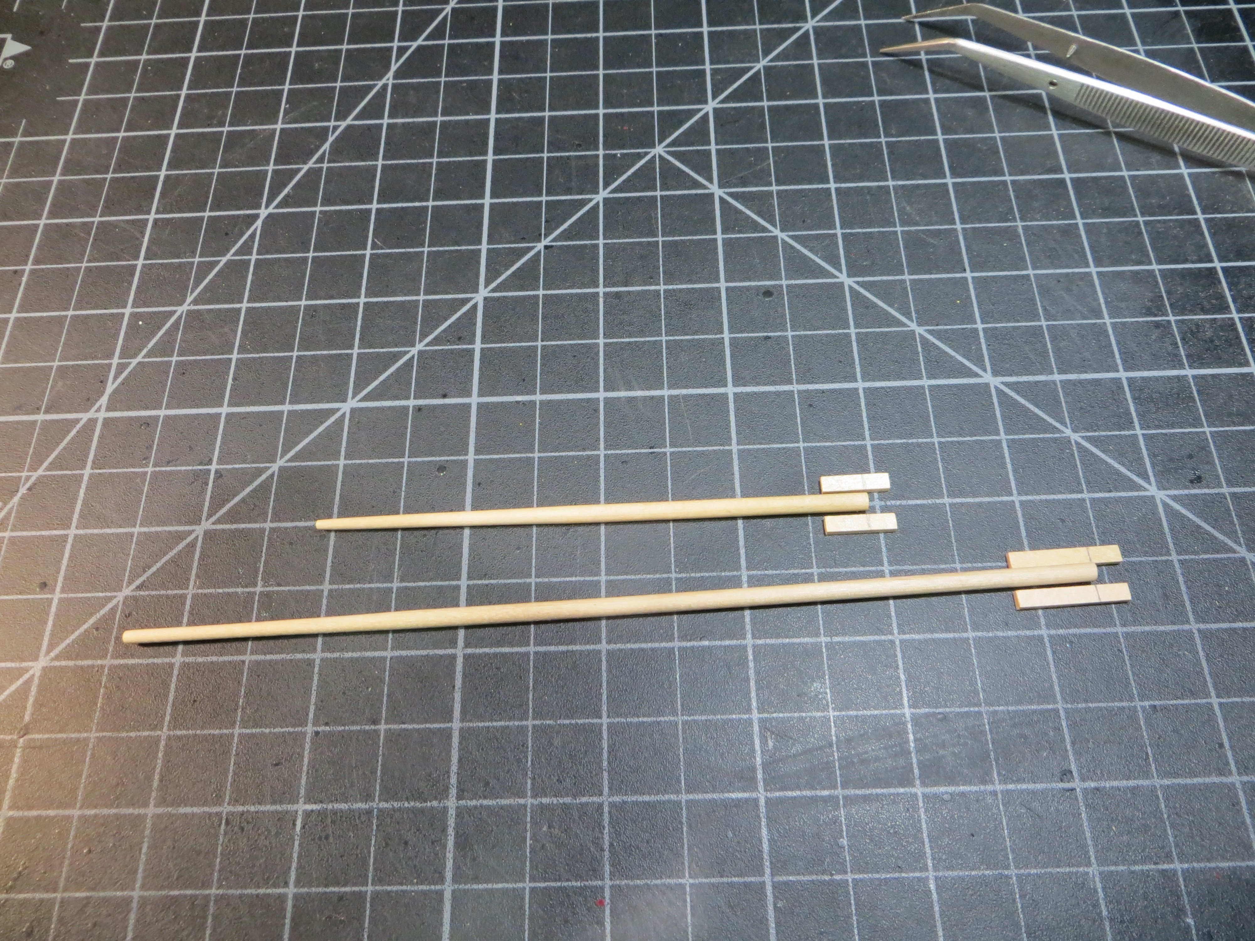
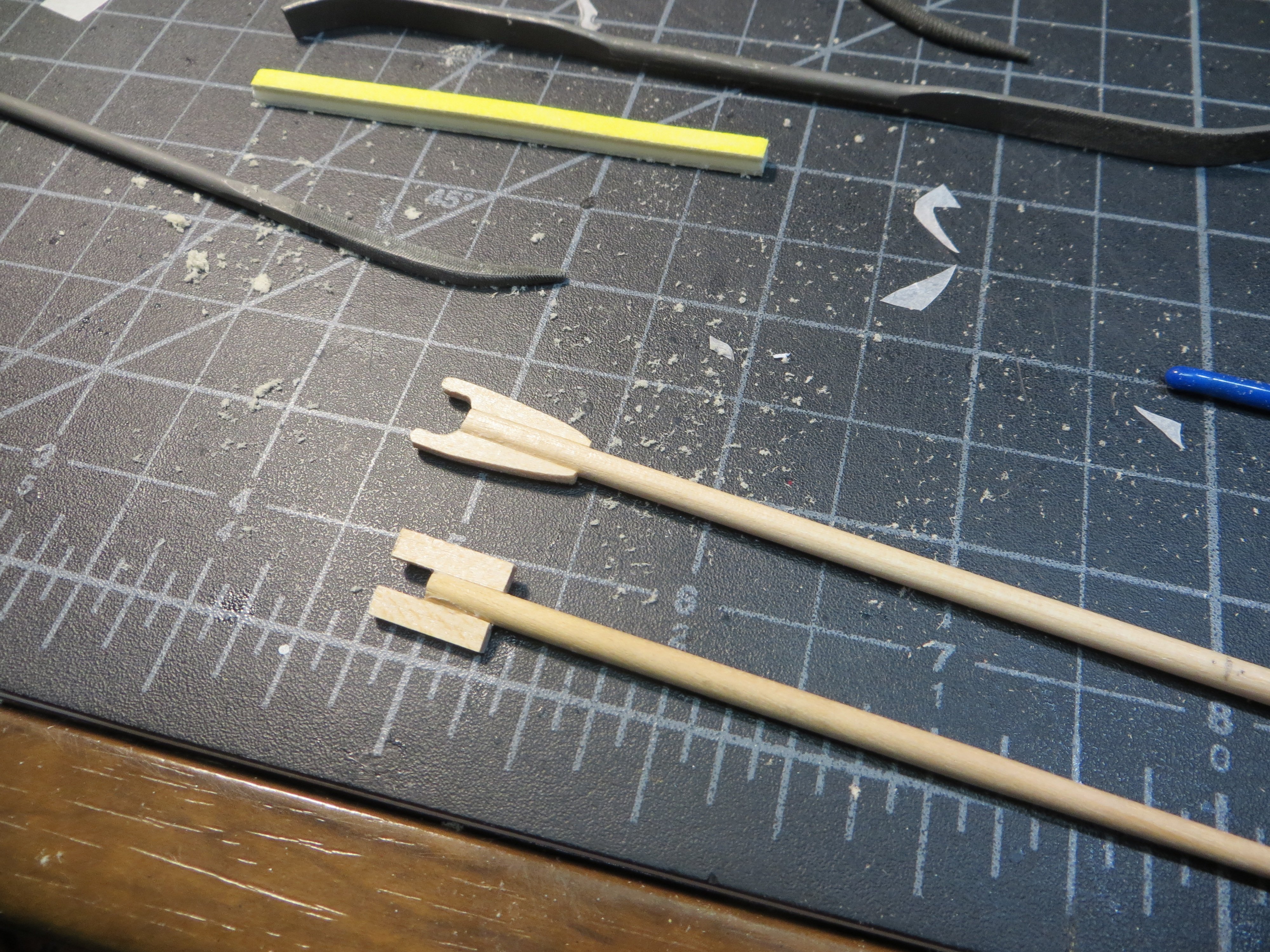
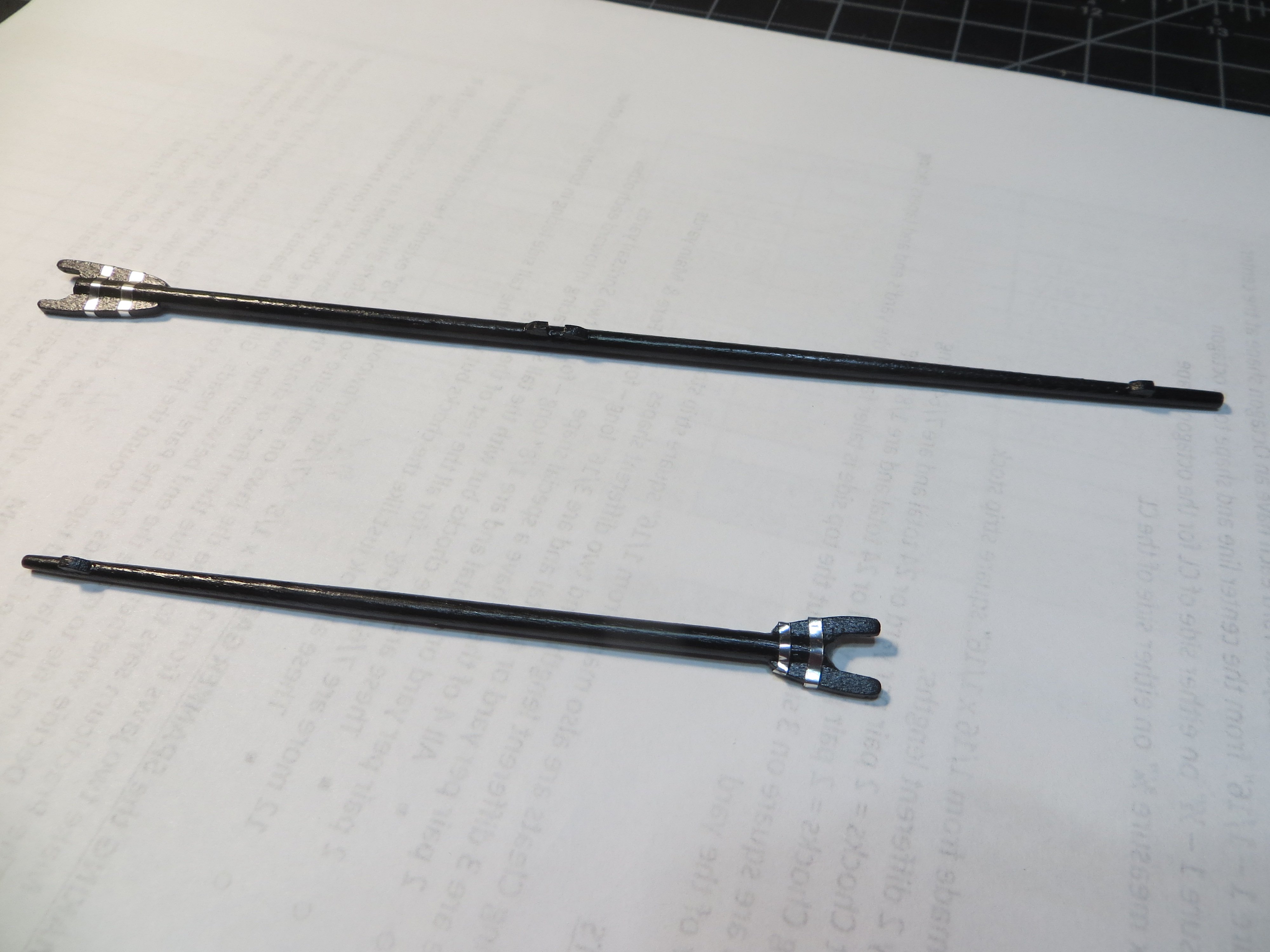
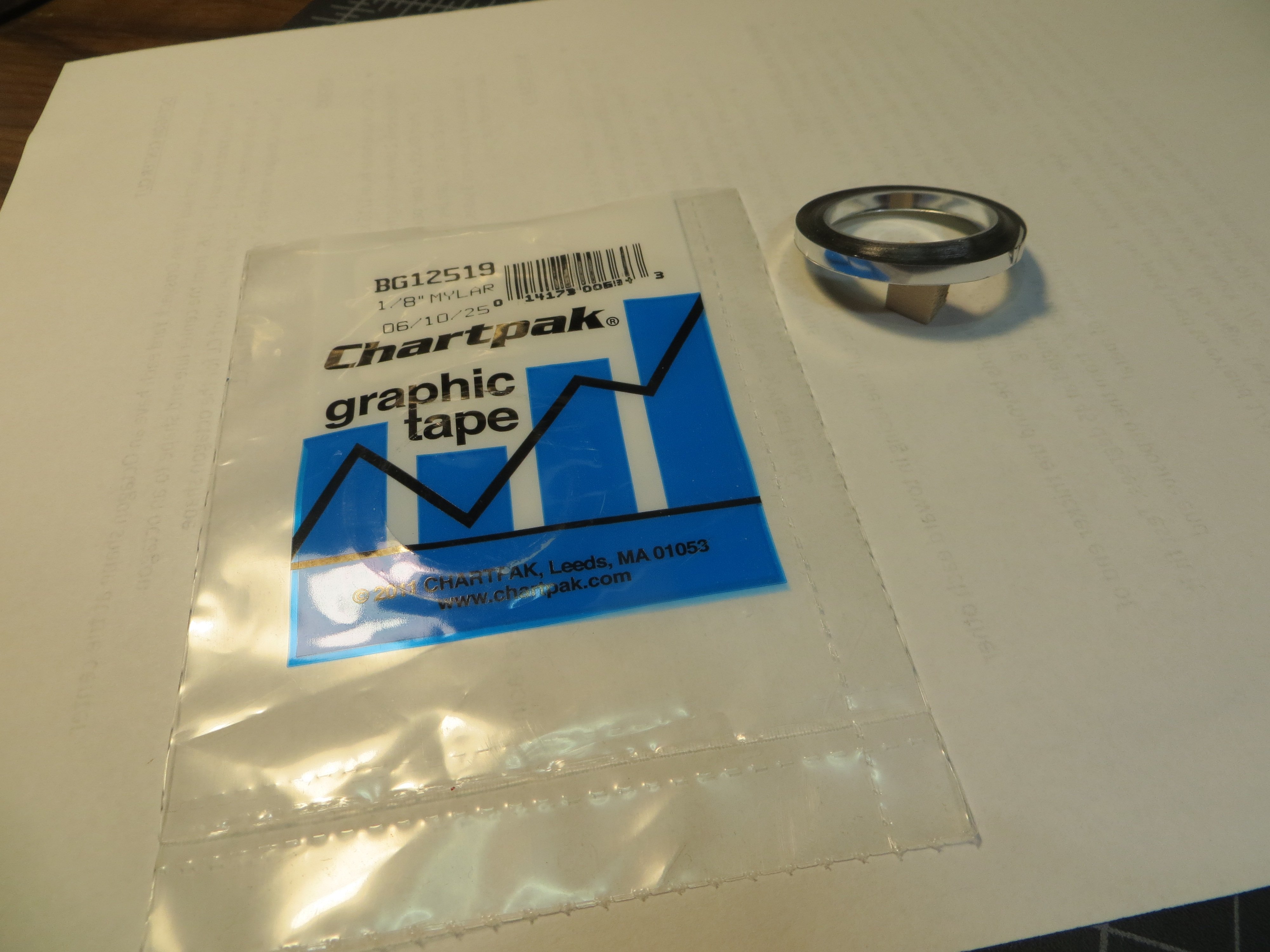
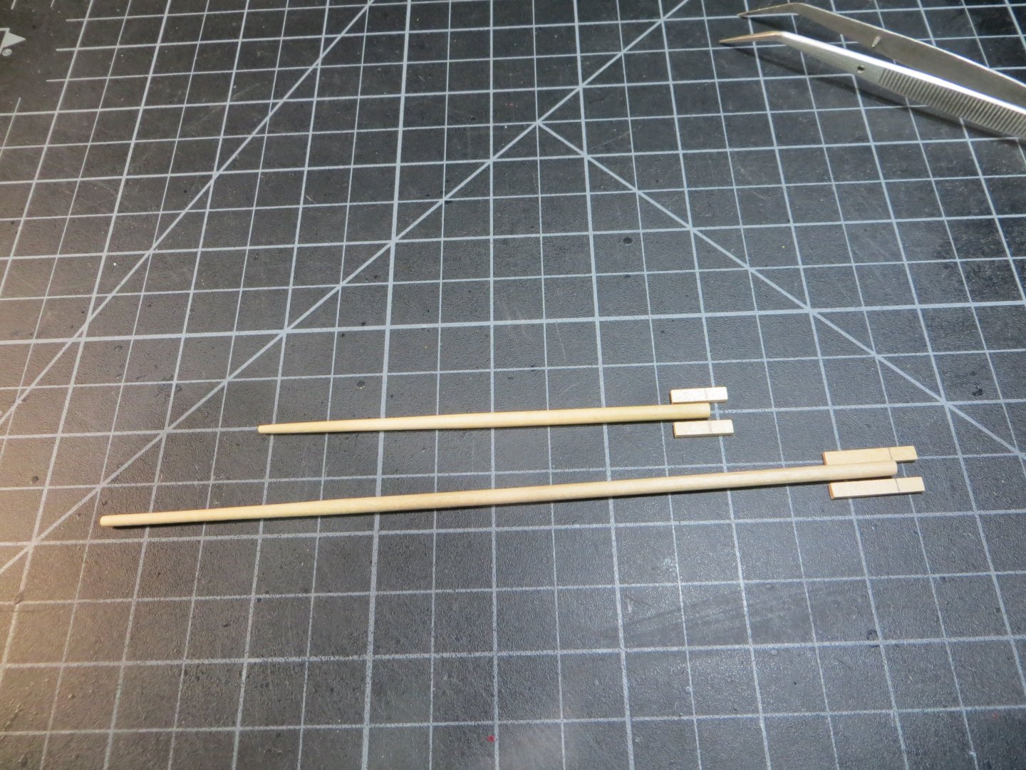
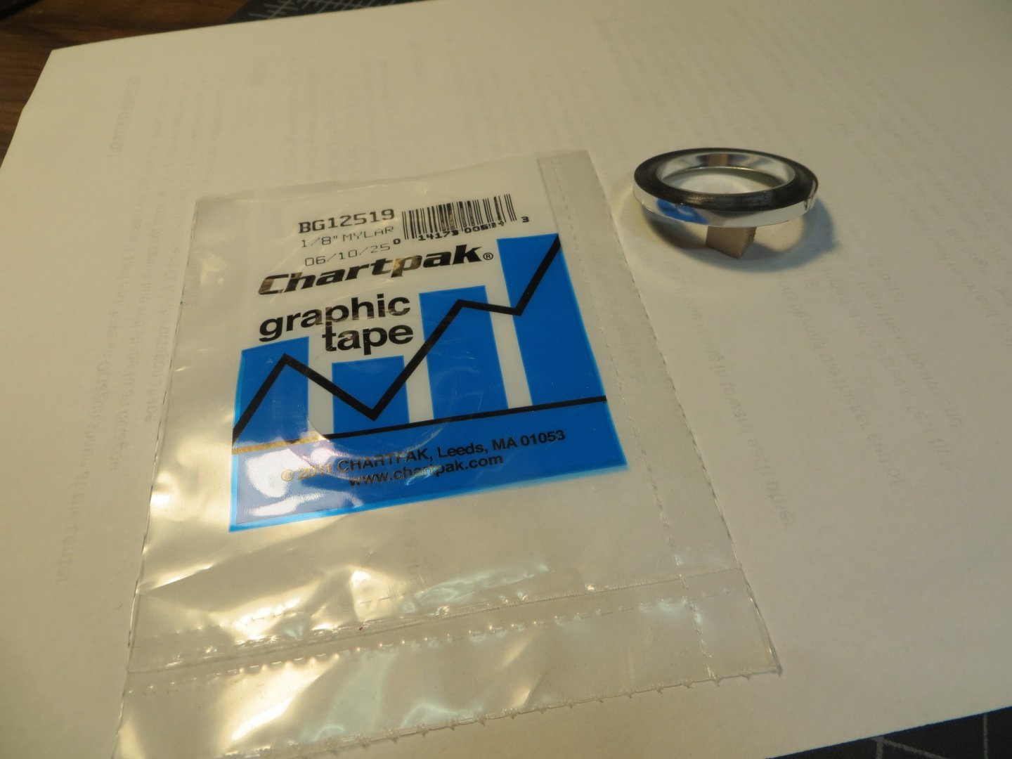
Finishing the Mizzen Spanker Gaff & Boom I finished the Gaff and Boom and as promised I am providing a post on these. The spars were made earlier. Now I have to add the jaws that will hold them to the Mizzen mast. Actually, the MS kit provides laser cut jaws, but I wanted to make my own. · A pair of jaws were cut from a piece of 1/16” x 1/8” stripwood and 3/4” long for the boom. According to the MS plans the jaws need to extend 1/4” past the end of the boom · At the same time, I cut another pair at ½” long for the gaff. These need to extend 1/8” past the end of the gaff. I marked these on all 4 jaws The jaws were glued to the end of the spars using PVA wood glue. I allowed the glue on the first side to dry overnight before attaching the other side After another night of glue drying for the second side, I started carving the shape of the jaws using files and sanding sticks. I checked the dry fit on the mast. Note that the mast-end of the gaff is carved at an angle. The gaff needs a long chock ¼” from the end. The boom chock is 3/8” from the end. Another pair of chocks goes in the center of the boom. I measured the position so these were right over the “iron horse” on the deck between the transom and rudder. Blocks will be rigged here later. Finally, the jaws have some metal bands wrapped around them. I simulated these with chrome colored graphic tape. I cut the 1/8” wide tape in half with my Exacto knife. I found this on Amazon. I used their gold-colored tape on my Bluenose build. The Practicum recommended using lead tape for balancing tennis rackets. But this tape worked just fine for me. I stained the spritsail yards with Minwax Natural same as the masts. Then applied wipe-on poly to everything. This completes the yards and spars. Here is the collection with the poly drying. I’m preparing to start rigging next. I have a bunch of miscellaneous tasks to finish up too. I have a question for you guys. I’m considering buying closed & open Hearts and Thimbles from Syren. How does Chuck measure these? Is it the diameter in millimeters of the opening? Or the width or length of the outside edge? I’m not sure what size to order. Thanks, Ed


-
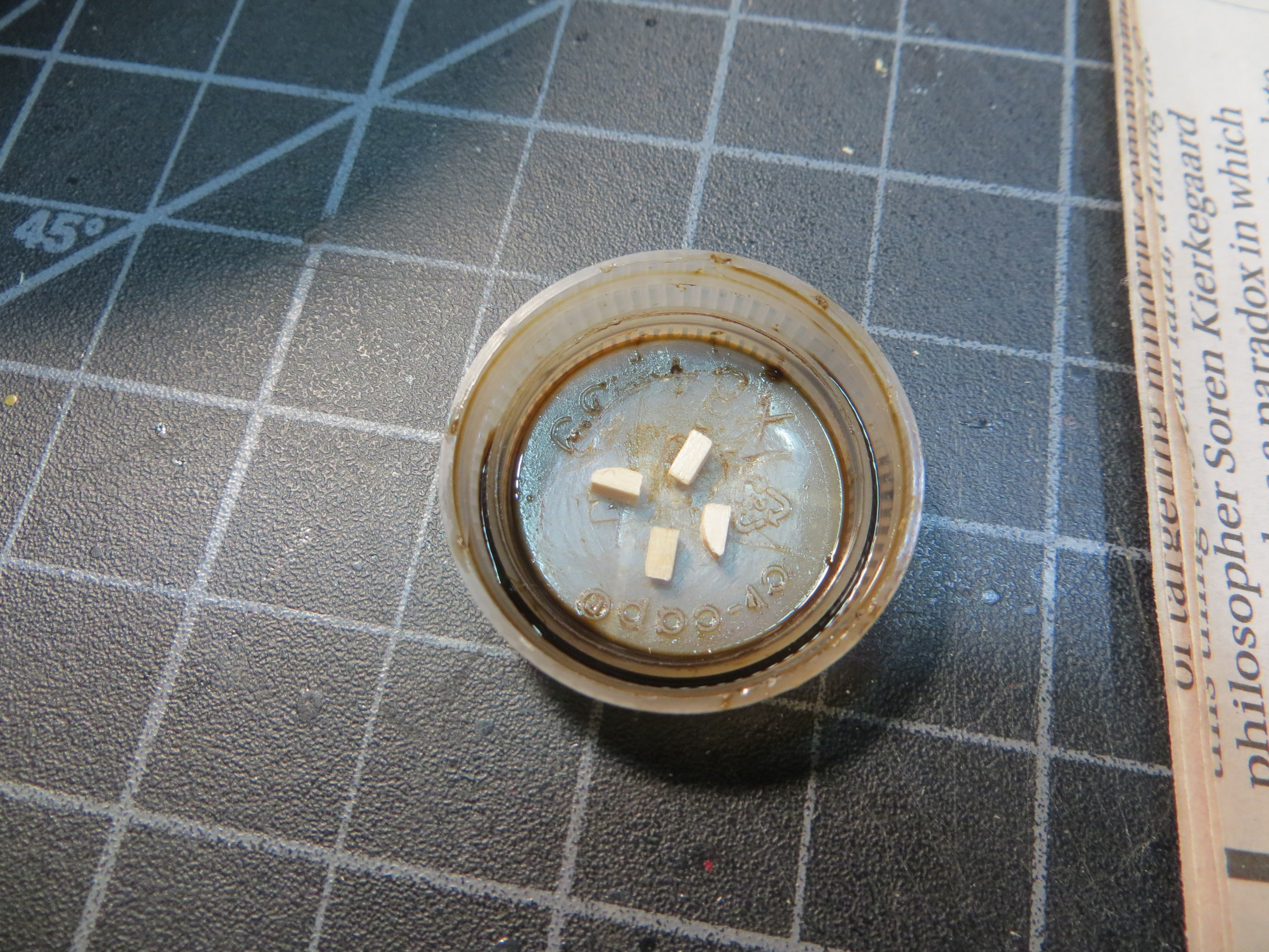
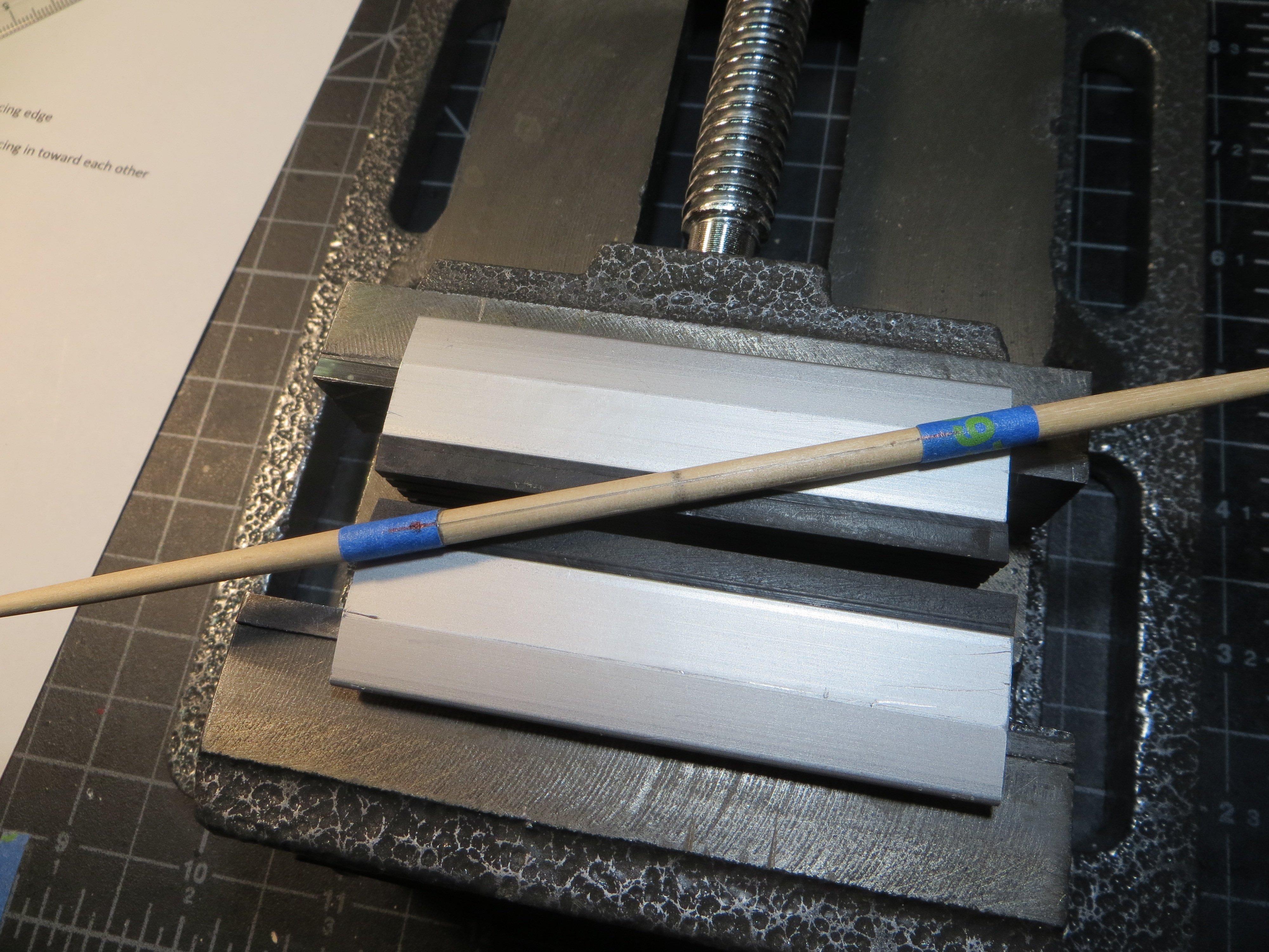
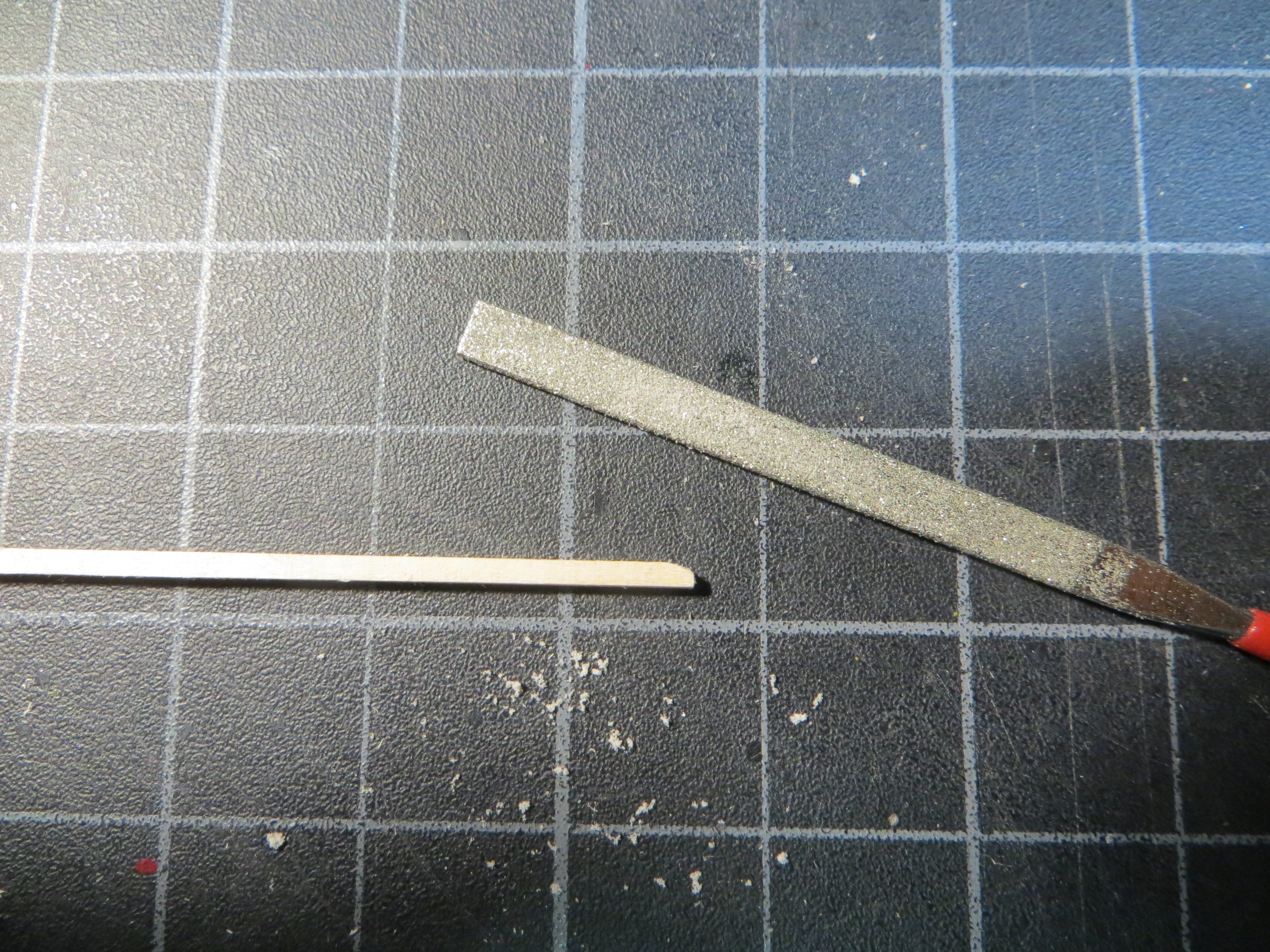
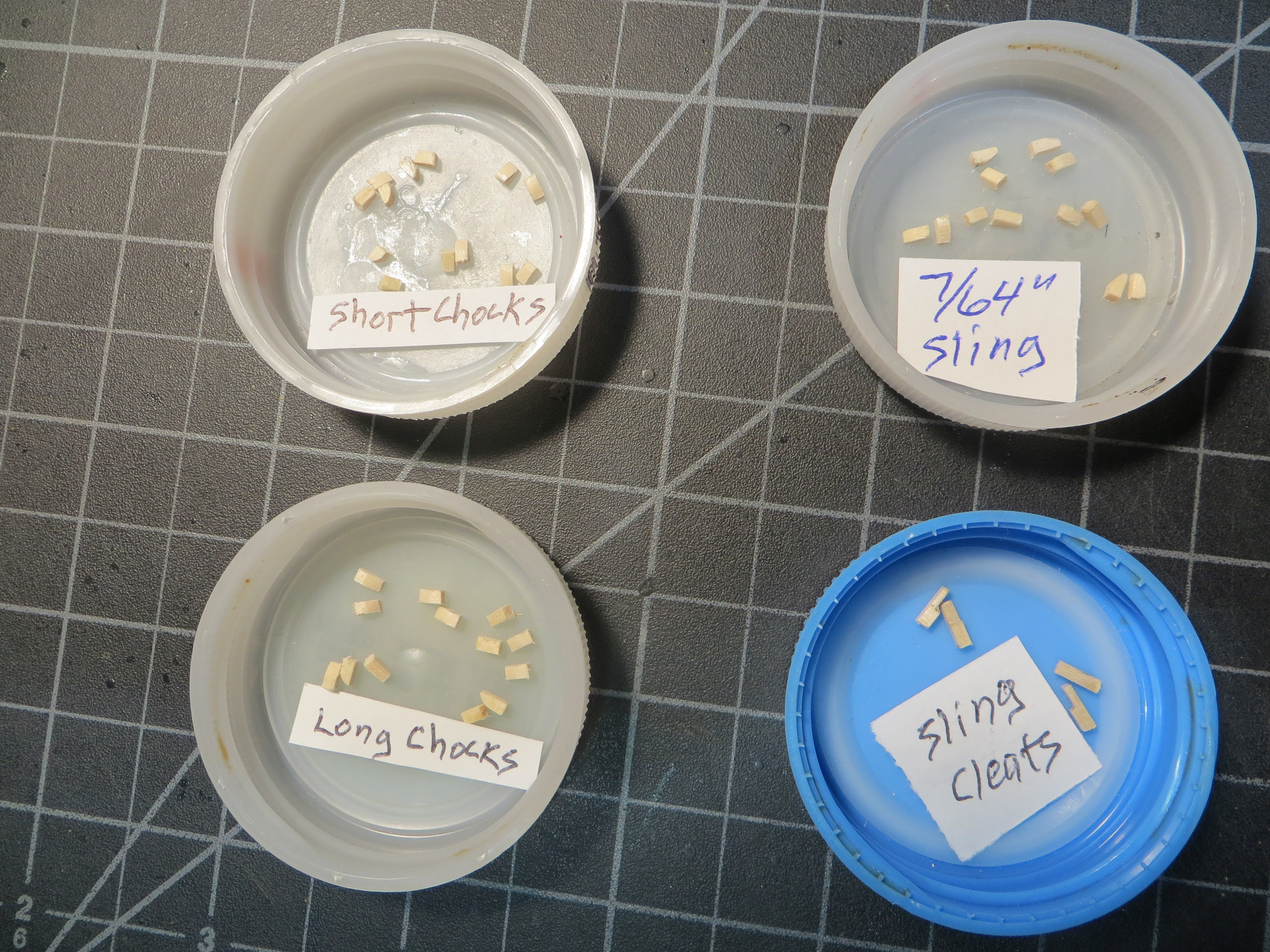
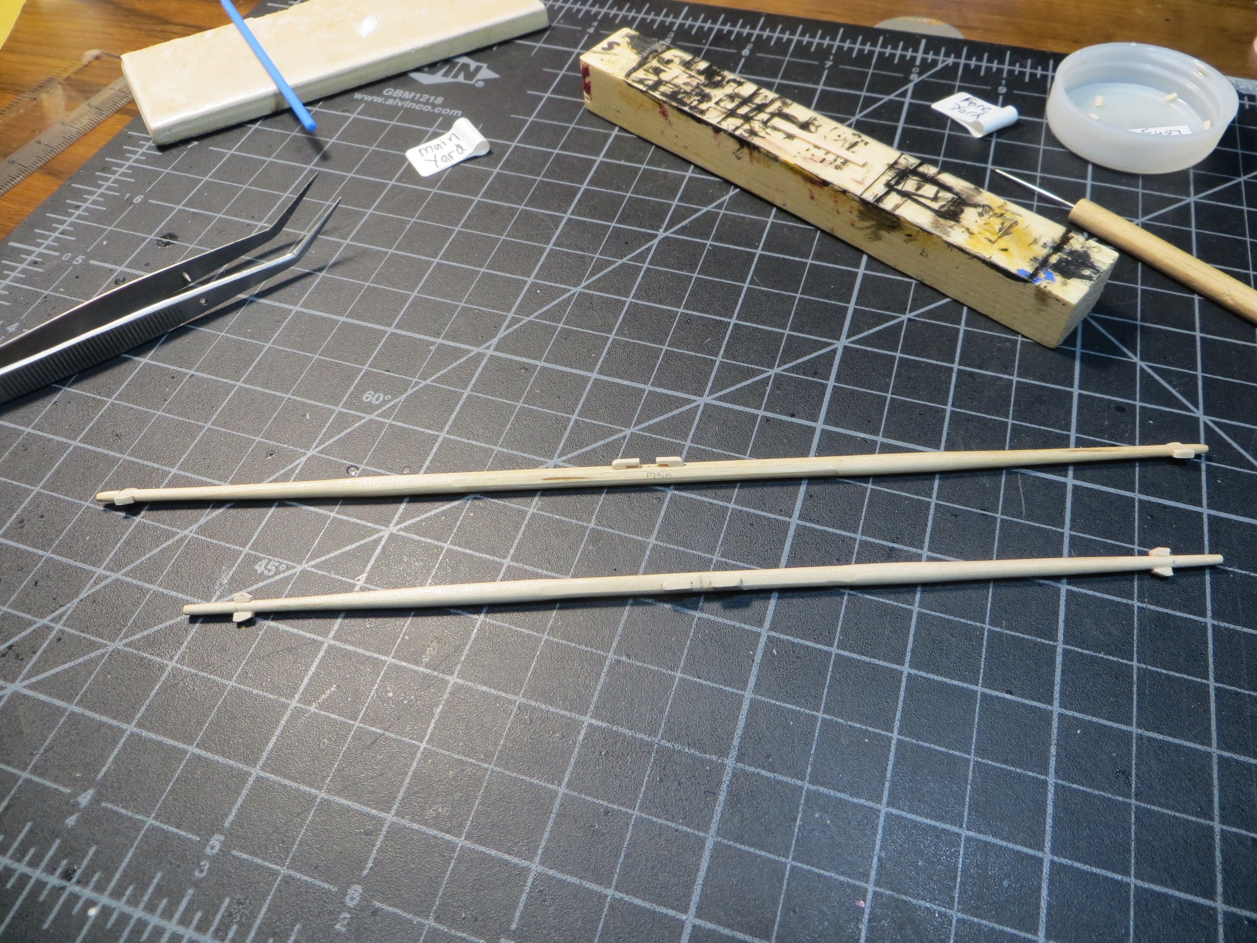
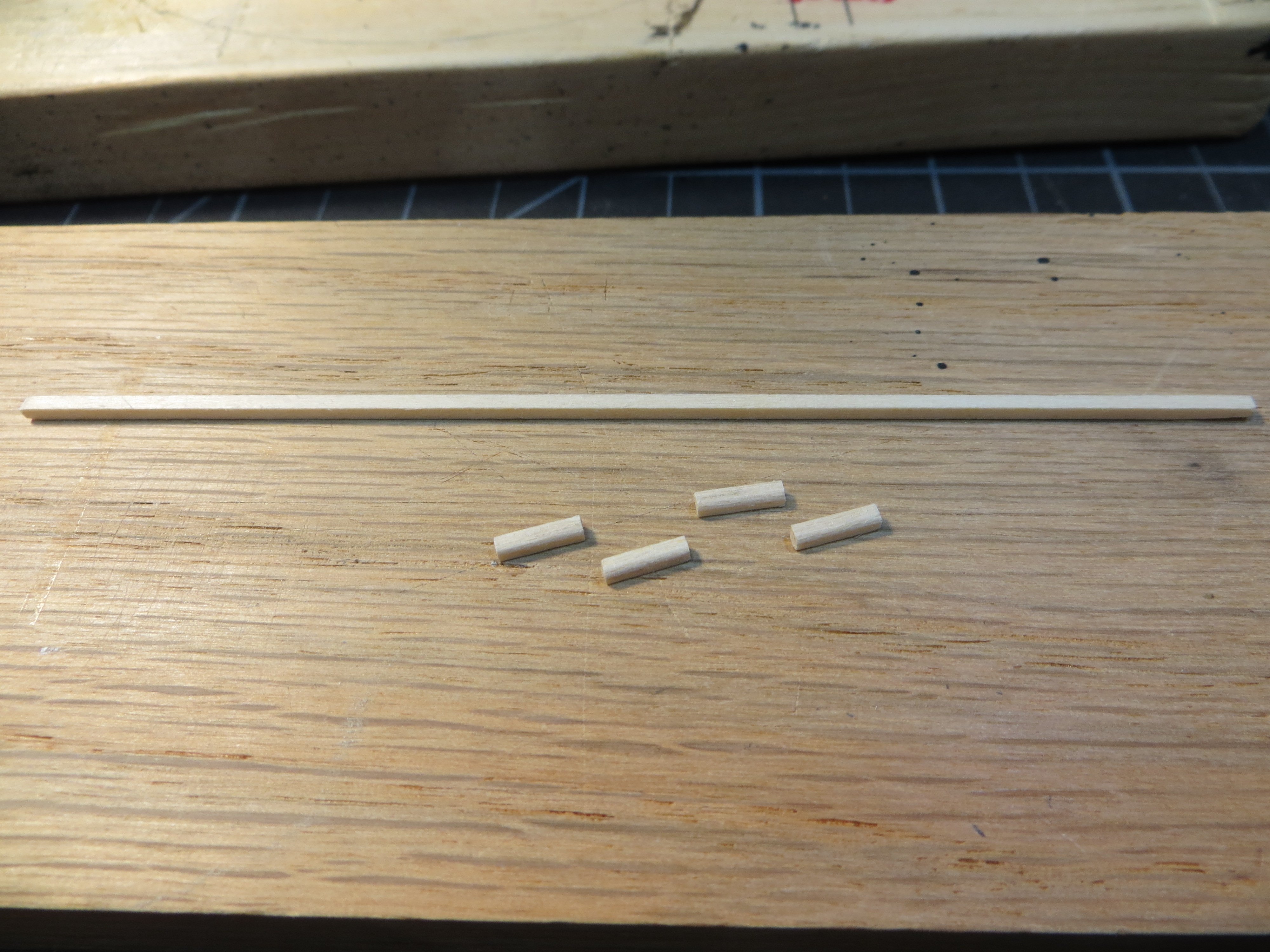
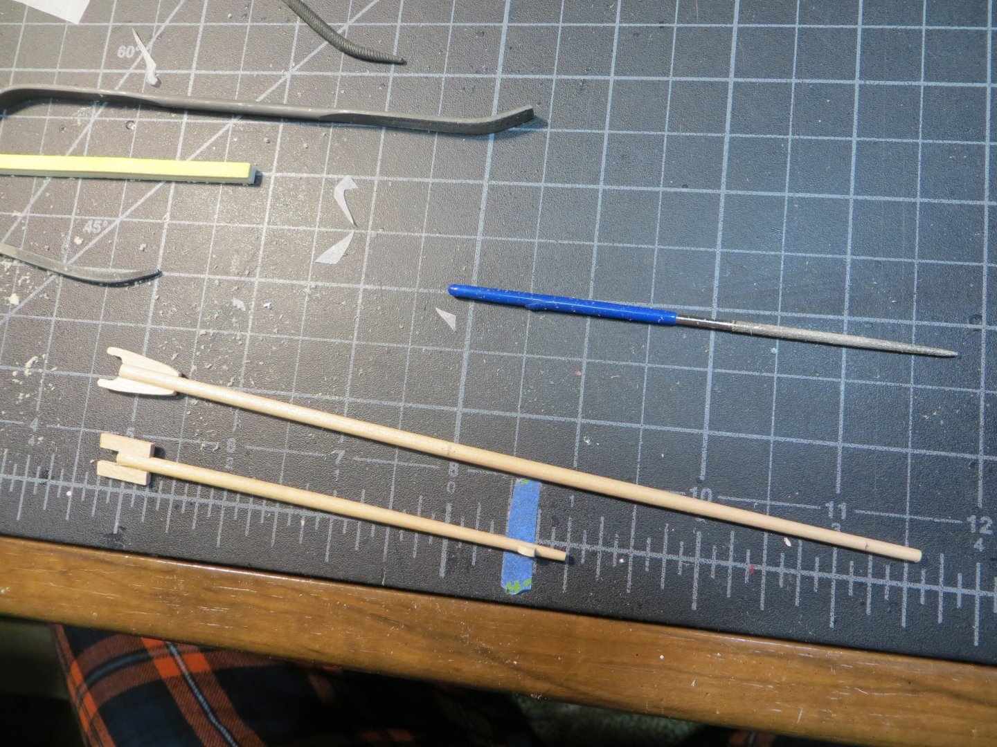
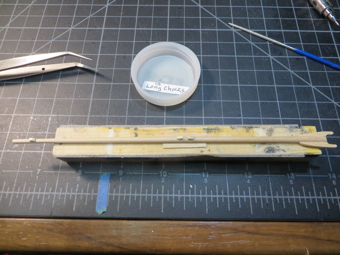
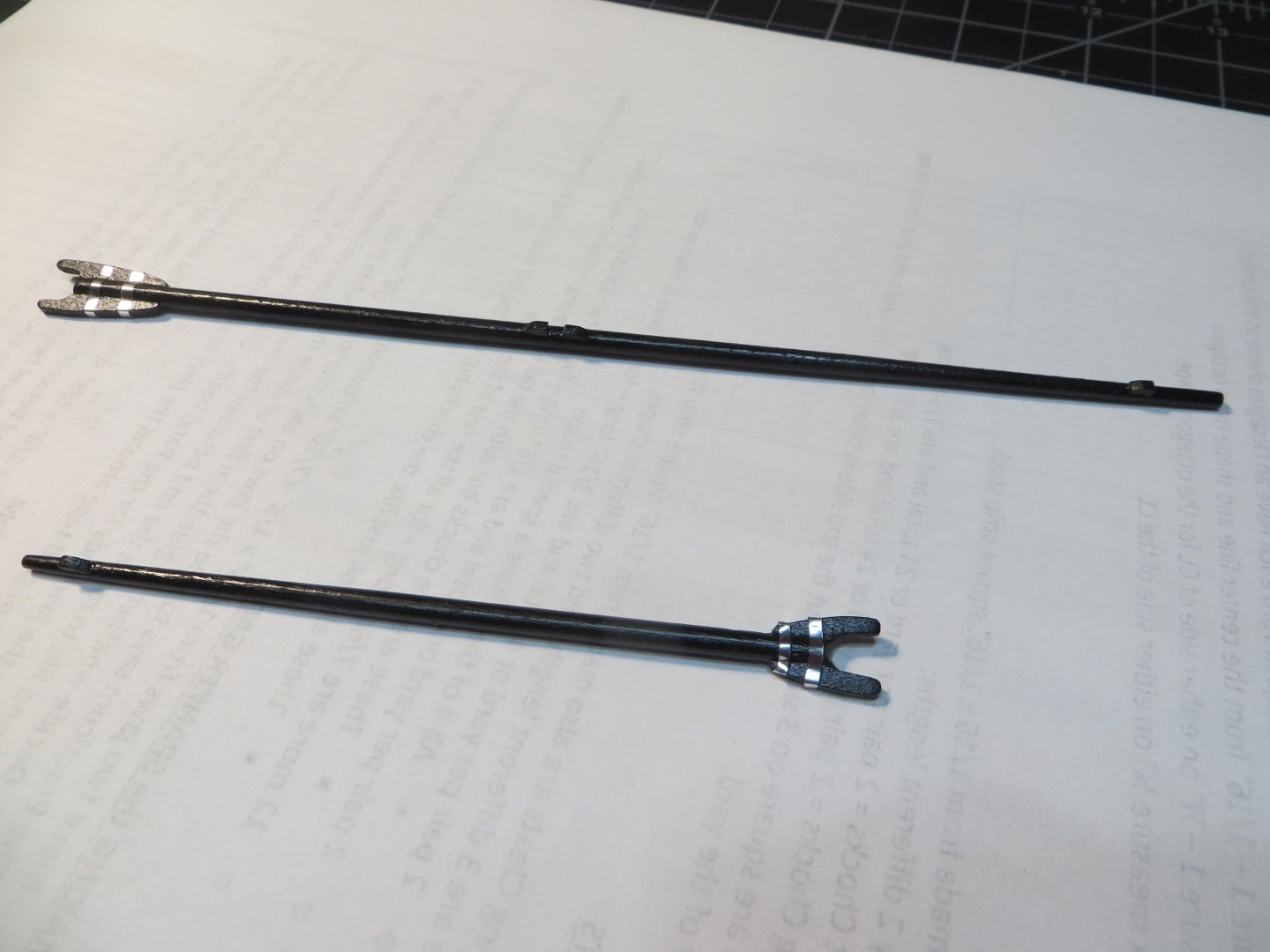
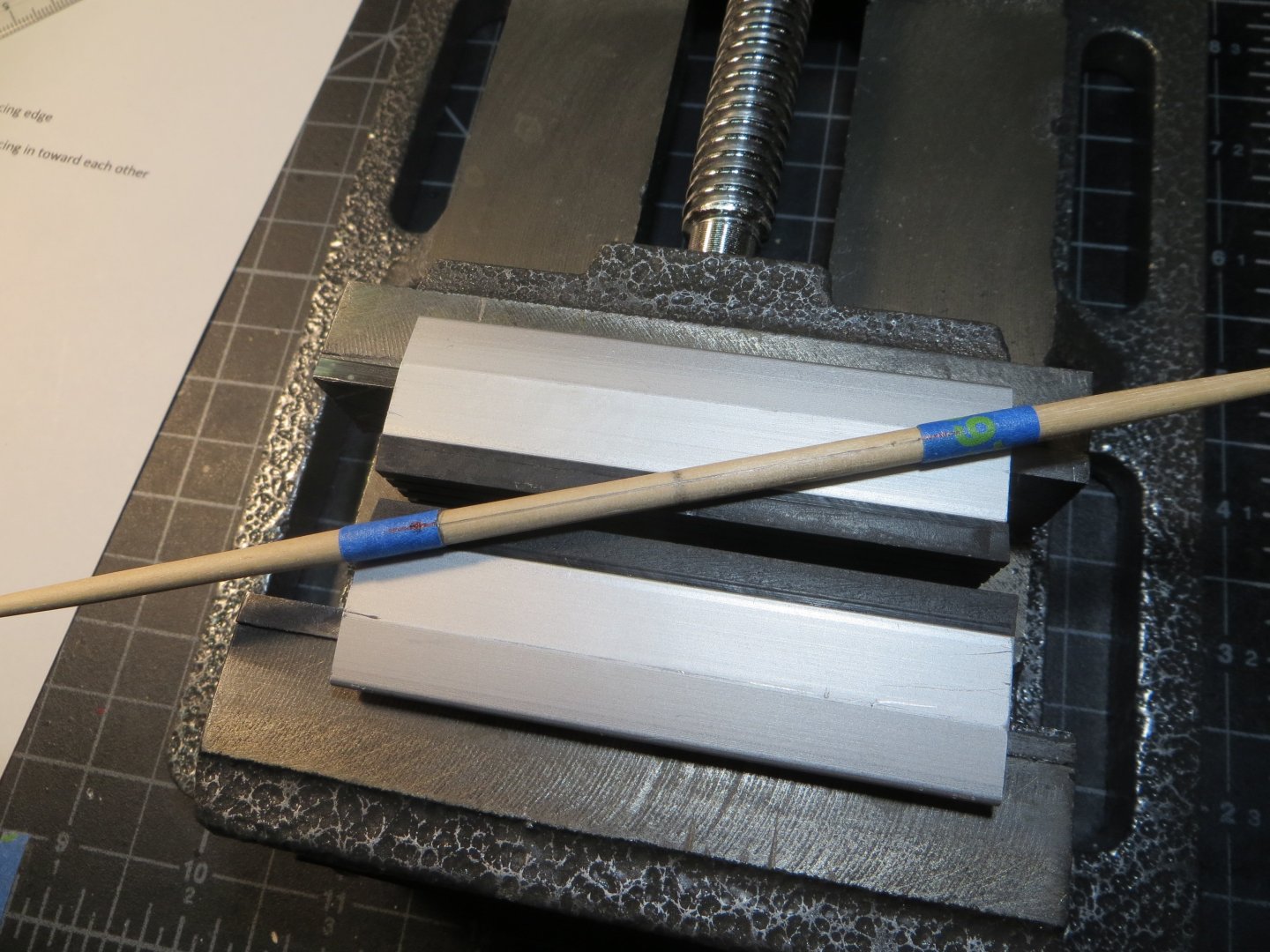
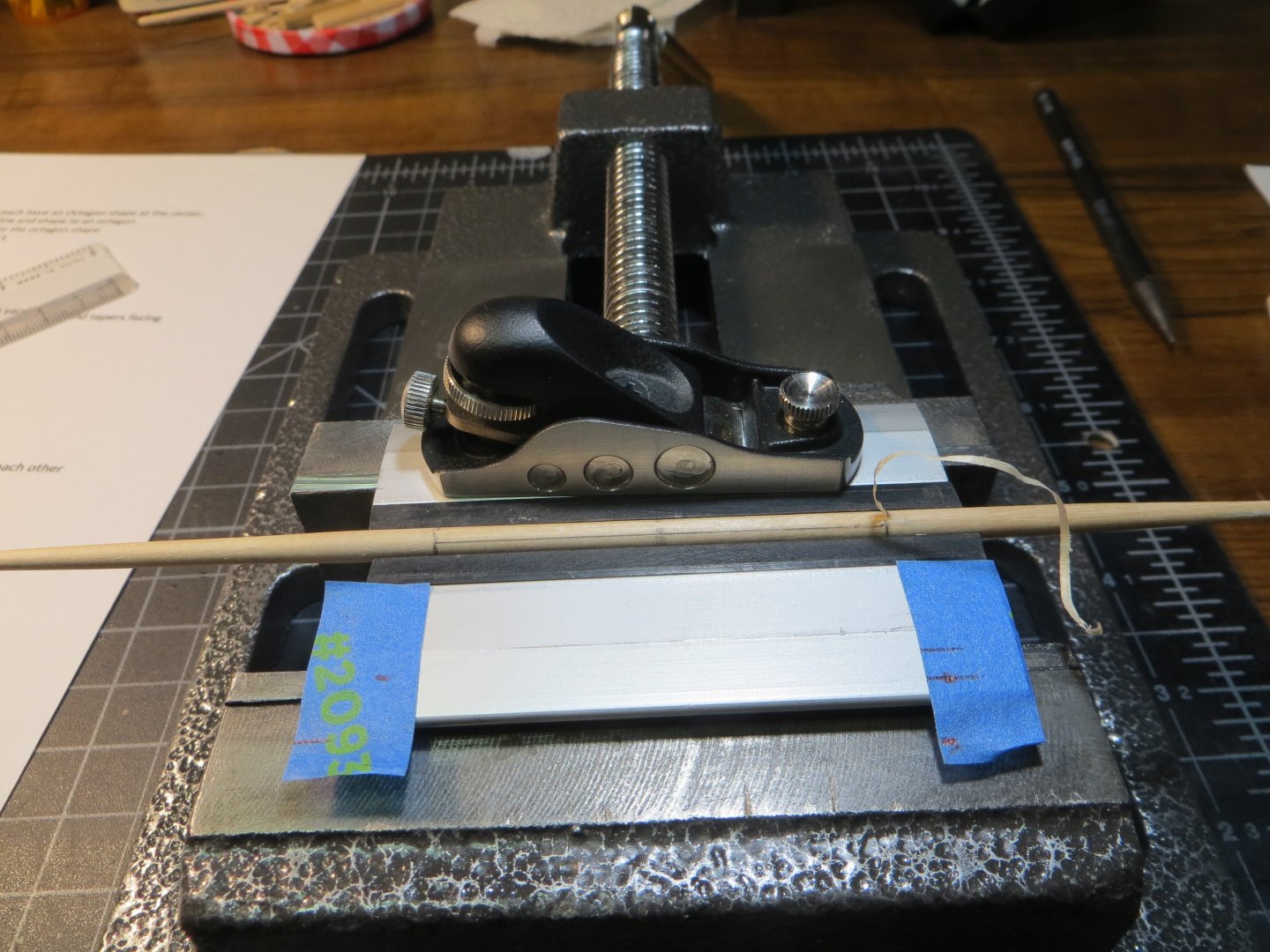
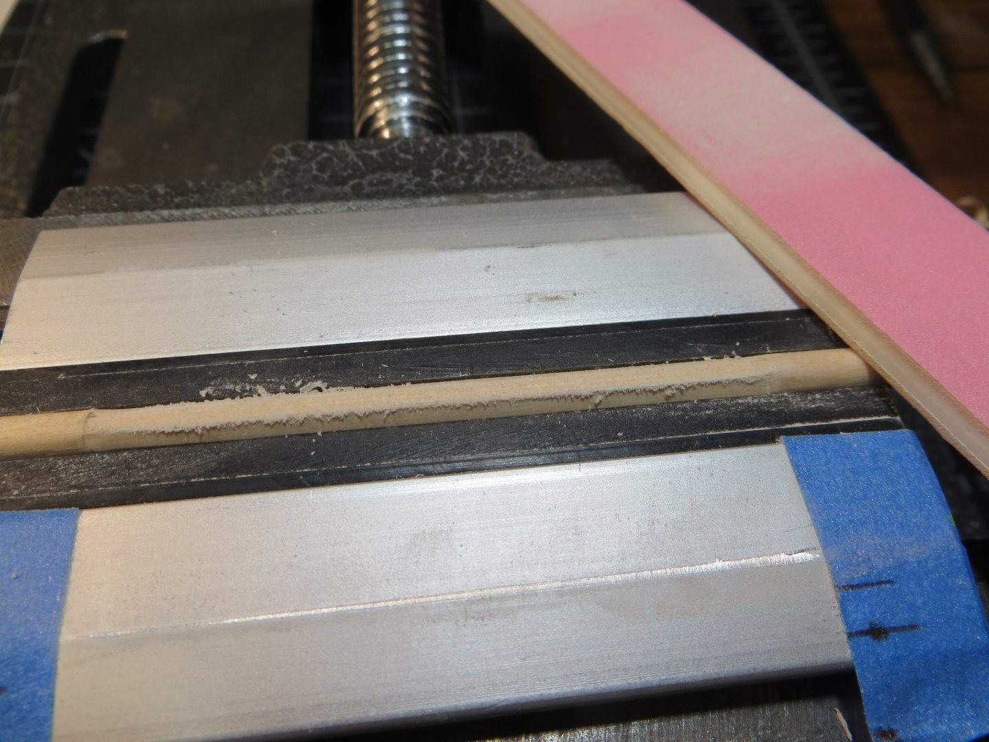
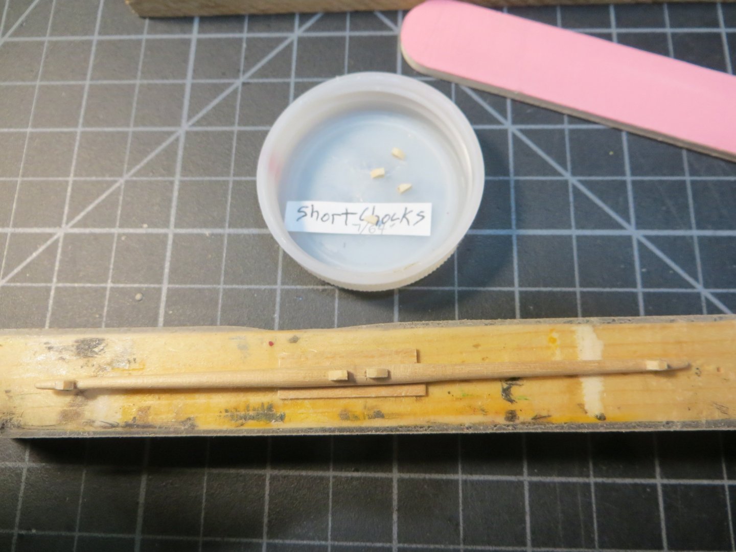
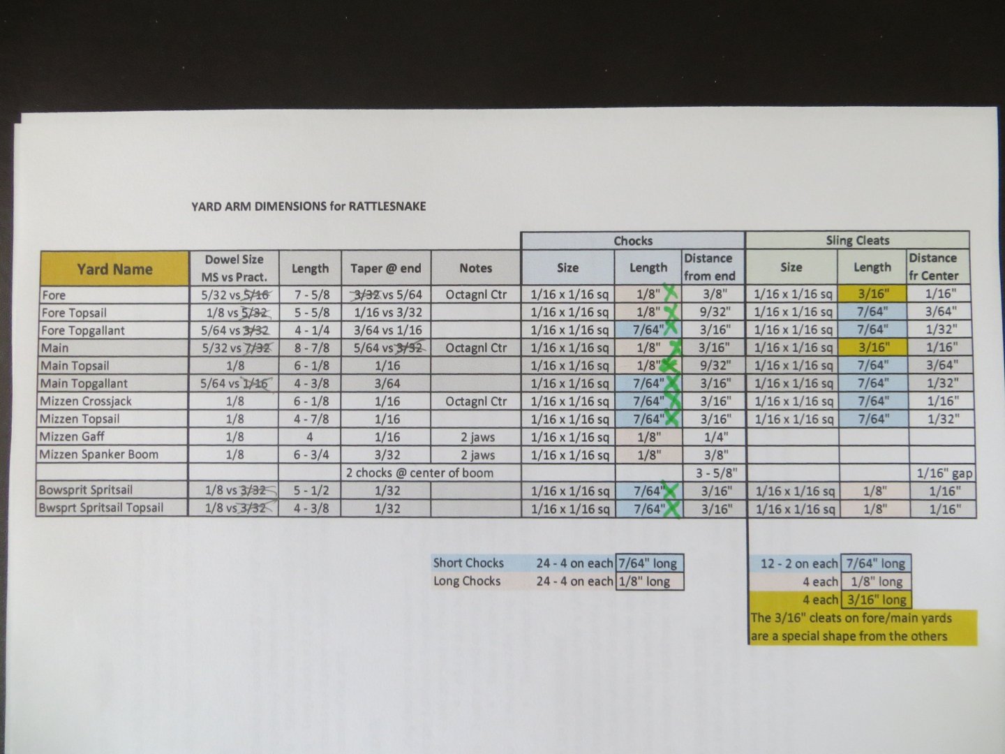
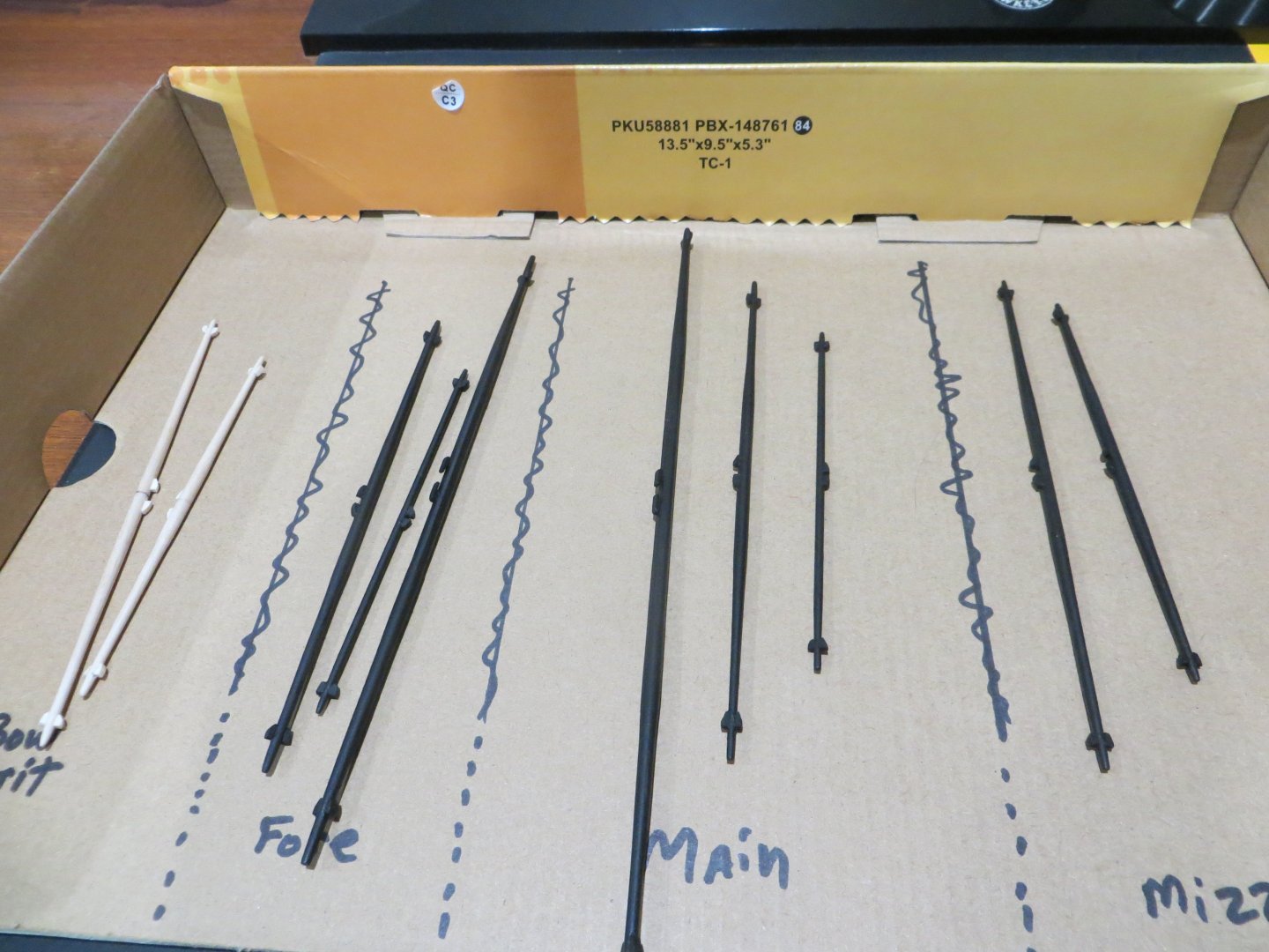
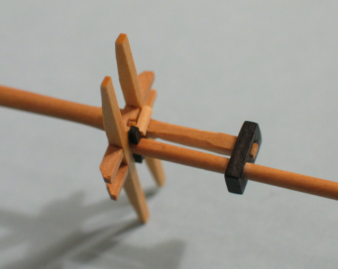
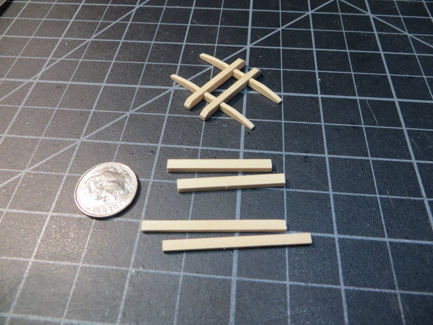
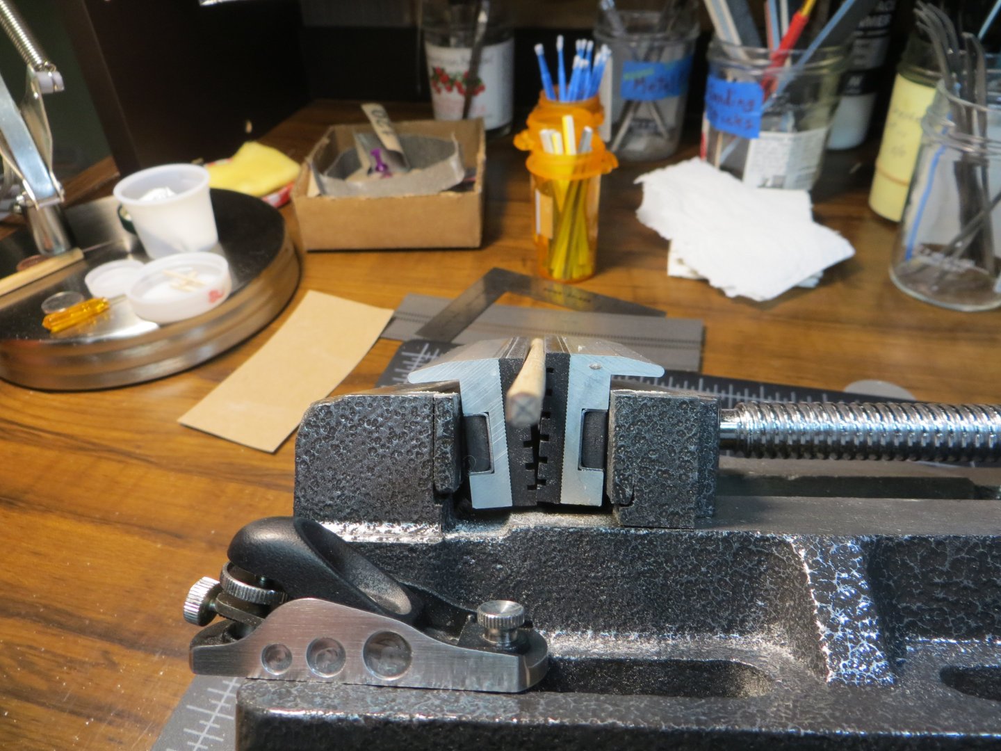
ADDING CHOCKS & SLING CLEATS TO THE YARDS I can’t believe my last update was on August 20th! In my defense, my wife and I were in France & Italy with friends for a lot of September and into October. When I got back, I spent a lot of Oct-Nov doing my fall clean-up work outside in preparation for winter. That’s a good thing because we have a foot of snow on the ground right now! Anyhow, I did get a little more work done on my ship. I completed the tedious task of making and installing 48 Chocks and 20 Sling Cleats. Ugh! Chocks go on the end of the yards and sling cleats are attached at the center with a specific spacing from the center line. Octagon Center Cuts Before getting to the chocks and sling cleats I had one last sanding/shaping task on the yards. The Fore Yard, Main Yard and Mizzen Crossjack Yard all have an octagon shape cut into the center portion. The width of the octagon section is different for each one. · Fore Yard: measure 1 – 1/16” on either side of the center line · Main Yard: measure 1 – ½” on either side of the CL · Mizzen Crossjack: measure ¾” on either side of the CL I measured off the distance from the CL and wrapped blue tape to mark the edges and to get straight lines for the cuts Then I put the yard in the vise and used the mini-plane to cut the dowel into a 4-sided square The sanding stick was used to take off the corners of the square and form an octagon shape. Making the Chocks & Sling Cleats Now I had to make LOTS of Chocks and Sling Cleats. As I got into it, I made some adjustments and corrected the actual numbers I needed. Below is a more accurate pic of my spreadsheet versus the one in my last post from August. Some of the sizes and numbers required were changed. Ignore the old one for the chocks and cleats detail. However, the tapering info has not changed and is still good. The Chocks have two different lengths. What I call “short” chocks I made at 7/64” long. What I call “long” chocks I made at 1/8”. The practicum would have you make them much smaller, but I could barely work with these tiny pieces! And if you drop one…forget it! You’ll never find it again! I don’t know where they go, but they’re just gone! They just fly out of the tweezers and disappear into thin air. It’s faster to make a new one. I have a hobby room carpet full of chocks! Now the process. First, the required length of the chock was marked on a 1/16” X 1/16” square piece of stripwood. Second, the top edge was sanded off on an angle to form a wedge with a flat front. Third, the chock was sawed off at the original mark using a miter box and razor saw. Here are three pics of the process. The Sling Cleats for the Fore and Main Yards are different than the others. They are 3/16” in length. They stay squared off for now. Before cutting it off the strip, I used an Exacto knife to cut a piece off as you can see these in the blue cap below. The sling cleats for the rest of the yards are just like the long chocks. I glued the sling cleats on first. This provided an easier visual check to make sure the topside chocks were in line with them. I did the sling cleats for the Fore & Main yards first. They were easier since I had a flat surface to glue them onto due to the octagon that was cut in at the center. Afterward I realized the MS blueprints were different from the practicum instructions. MS shows the chocks in a vertical position and the practicum shows them on the same plane as the sling cleats. MS doesn’t show any of the other chocks on the blueprints. So, I decided to just leave these two the way they were and I glued the rest of them on plane with the cleats. I hope this doesn’t make that much difference. In order to get a good fit on the rounded yard I filed a groove on the bottom side of the chocks and cleats with a round file. This was the most tedious step in the process. Did I mention how tiny these things are? The spreadsheet measurement was used to mark the location of each piece on the yard. I used wood glue (PVA) to attach them all. Here are the Fore & Main Yards. I made a simple jig with double faced tape and some scrap wood to hold the yard straight while I glued the parts on. I allowed the front side to dry overnight before adding the chocks on the aft side. It was difficult to get everything perfectly aligned. After completing the assembly, I painted everything with 2 coats of black acrylic. Here are the yards at this point in time. I intend to stain the 2 spritsail yards the same as the masts. This isn’t done yet. I also need to put on a coat or two of polyurethane, once I’m sure nothing else needs to be wood glued on. I am working on the cleats and jaws for the mizzen gaff and boom right now. I will follow-up with a separate posting when finished. Hope everyone is enjoying their Christmas Holidays! Ed


-
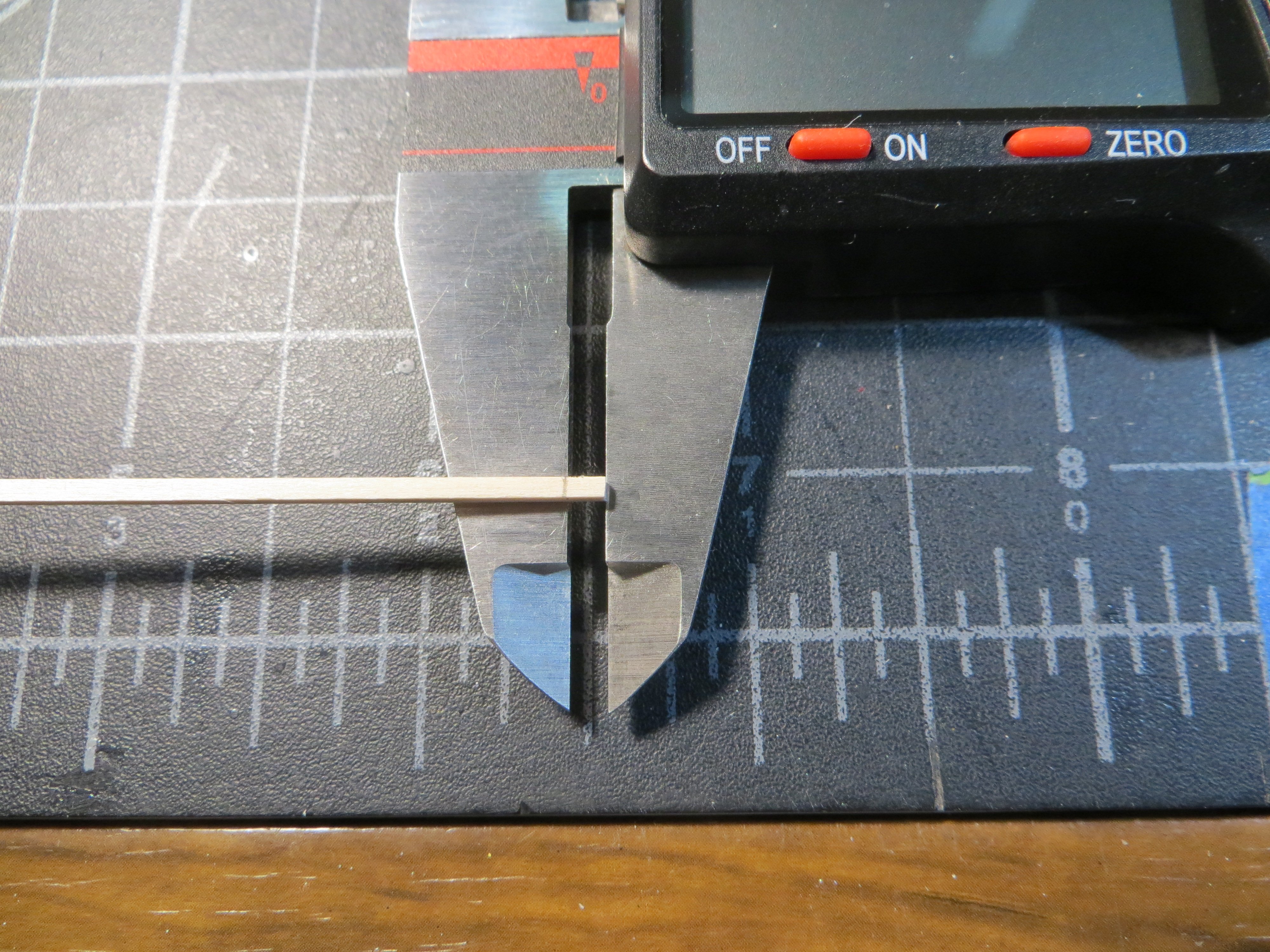
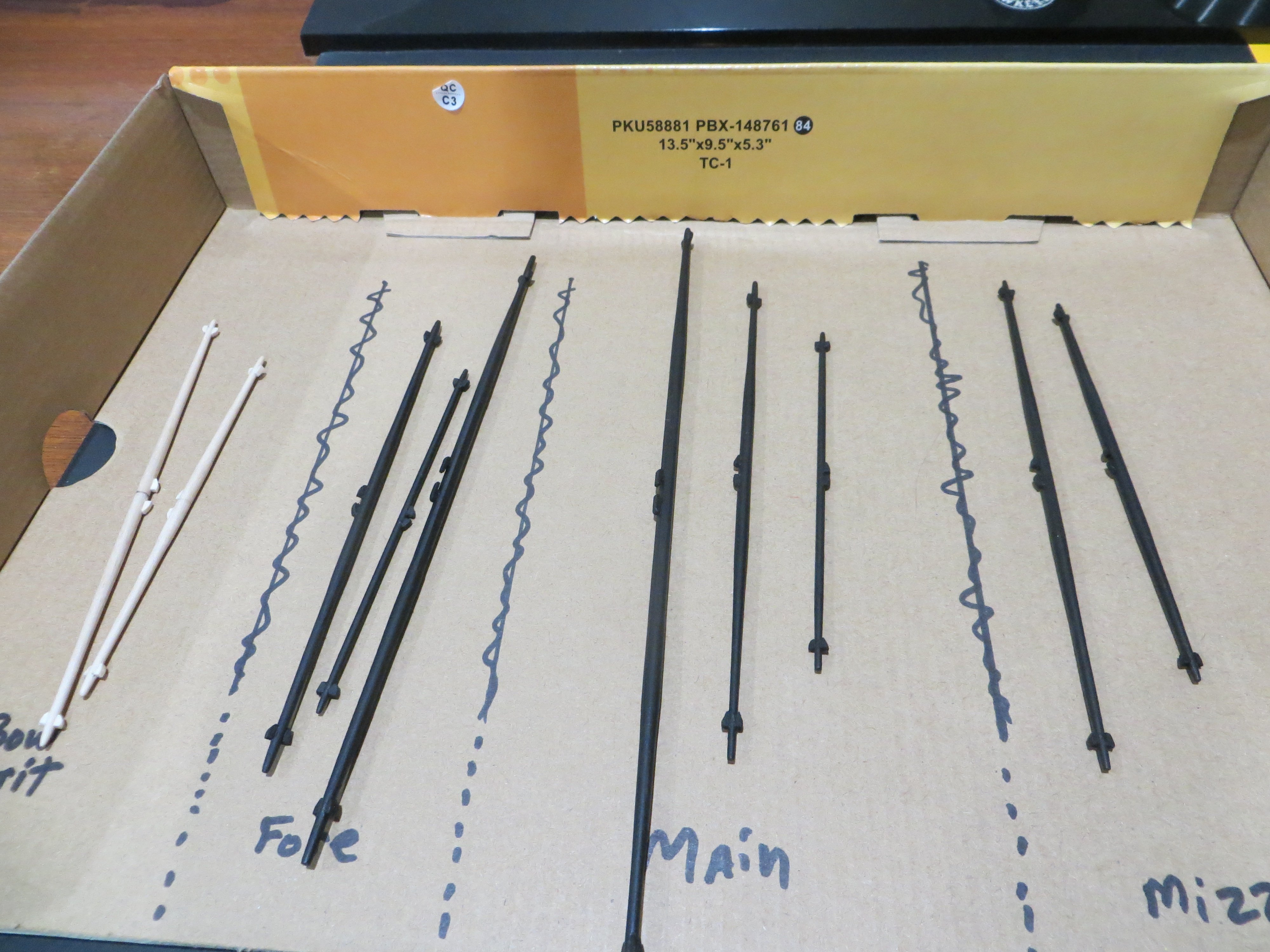
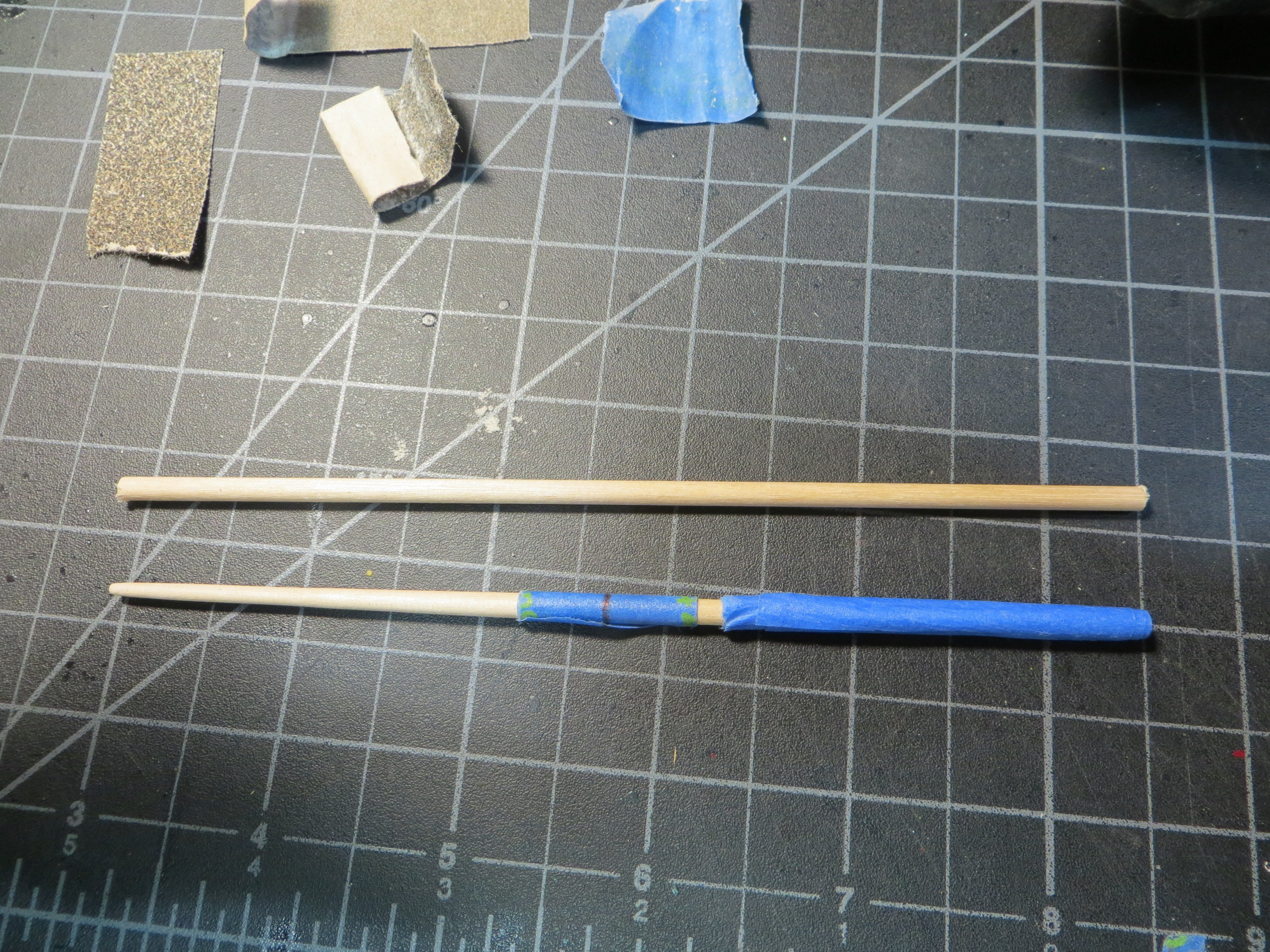
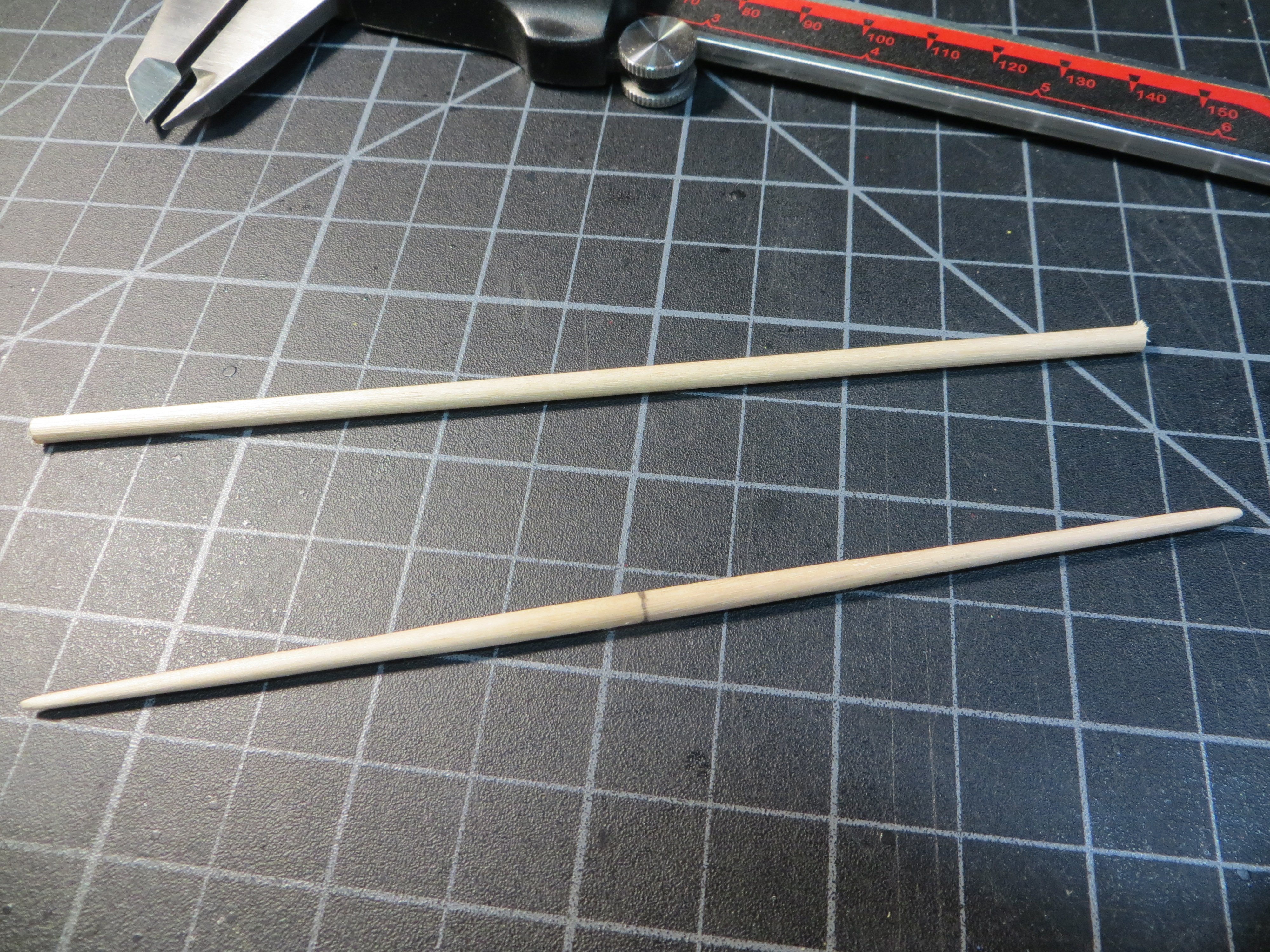
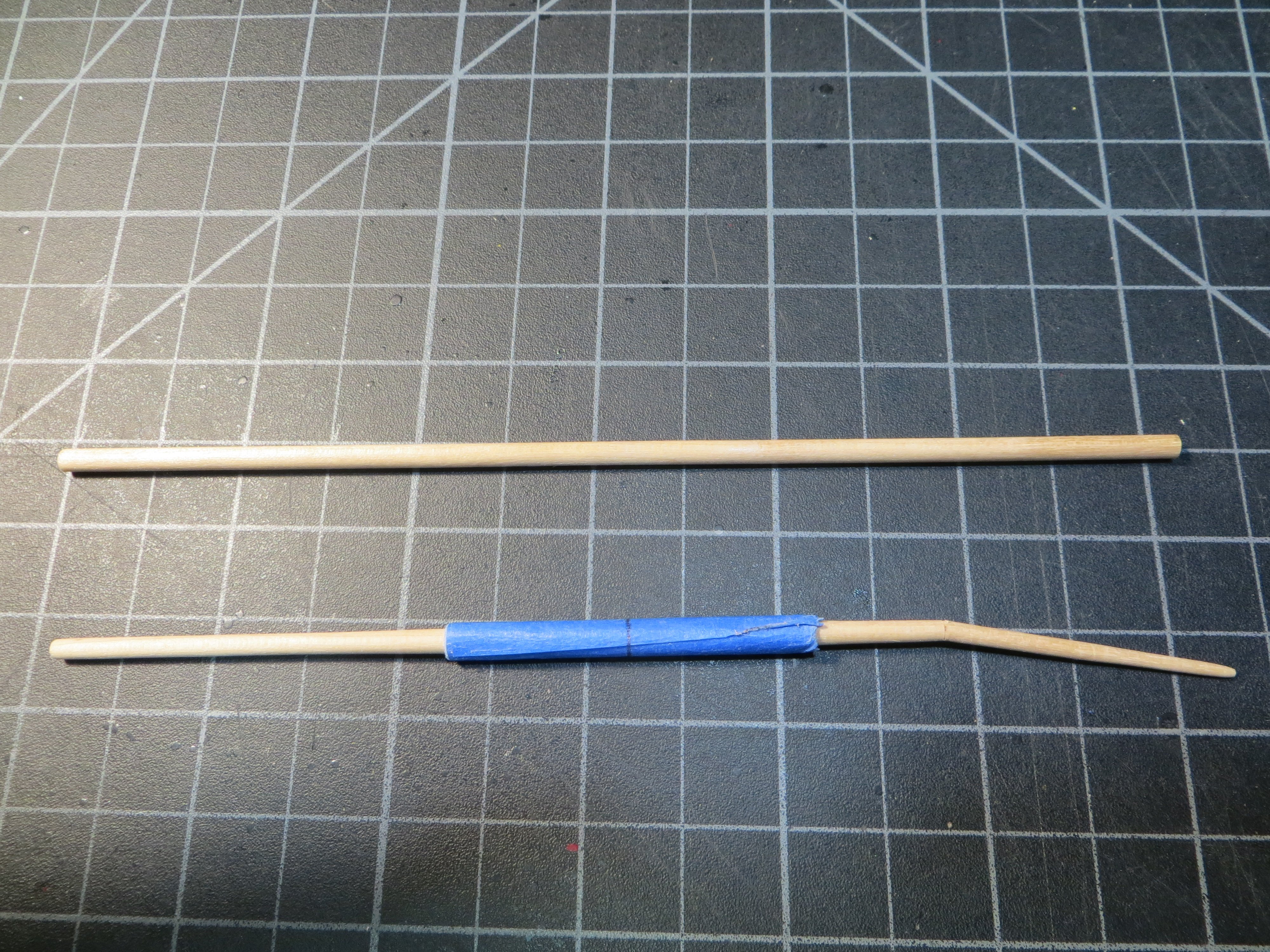
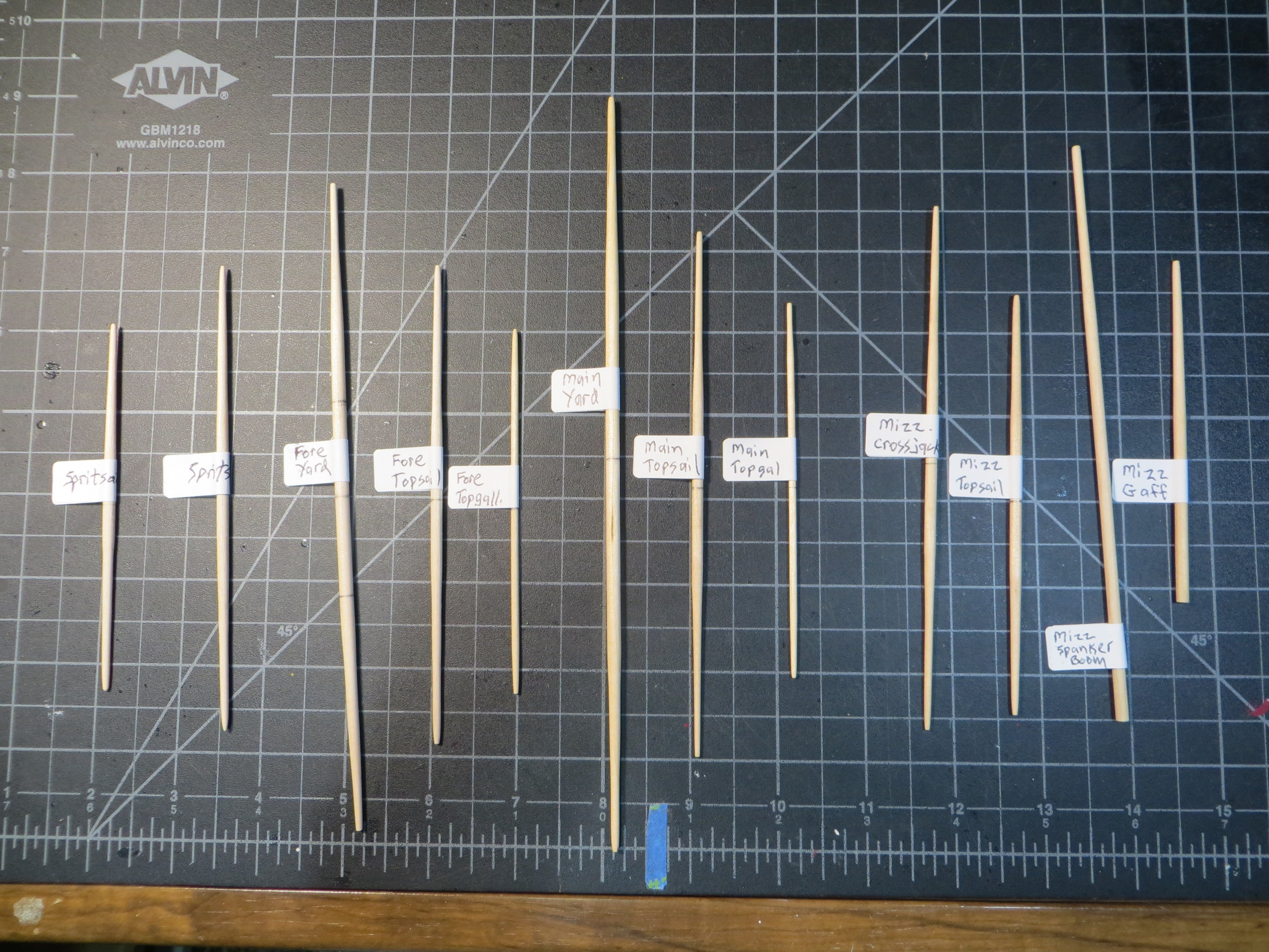
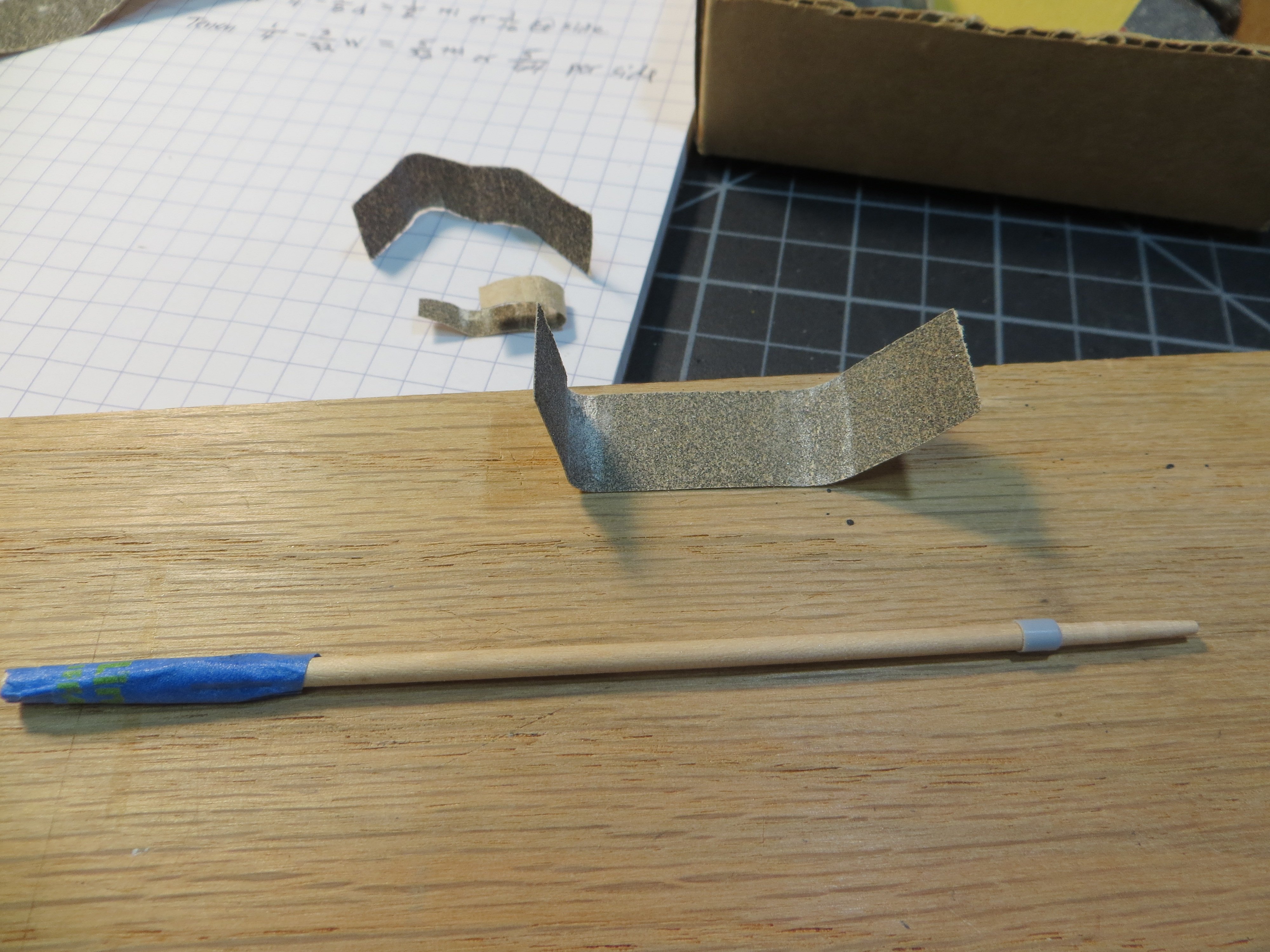
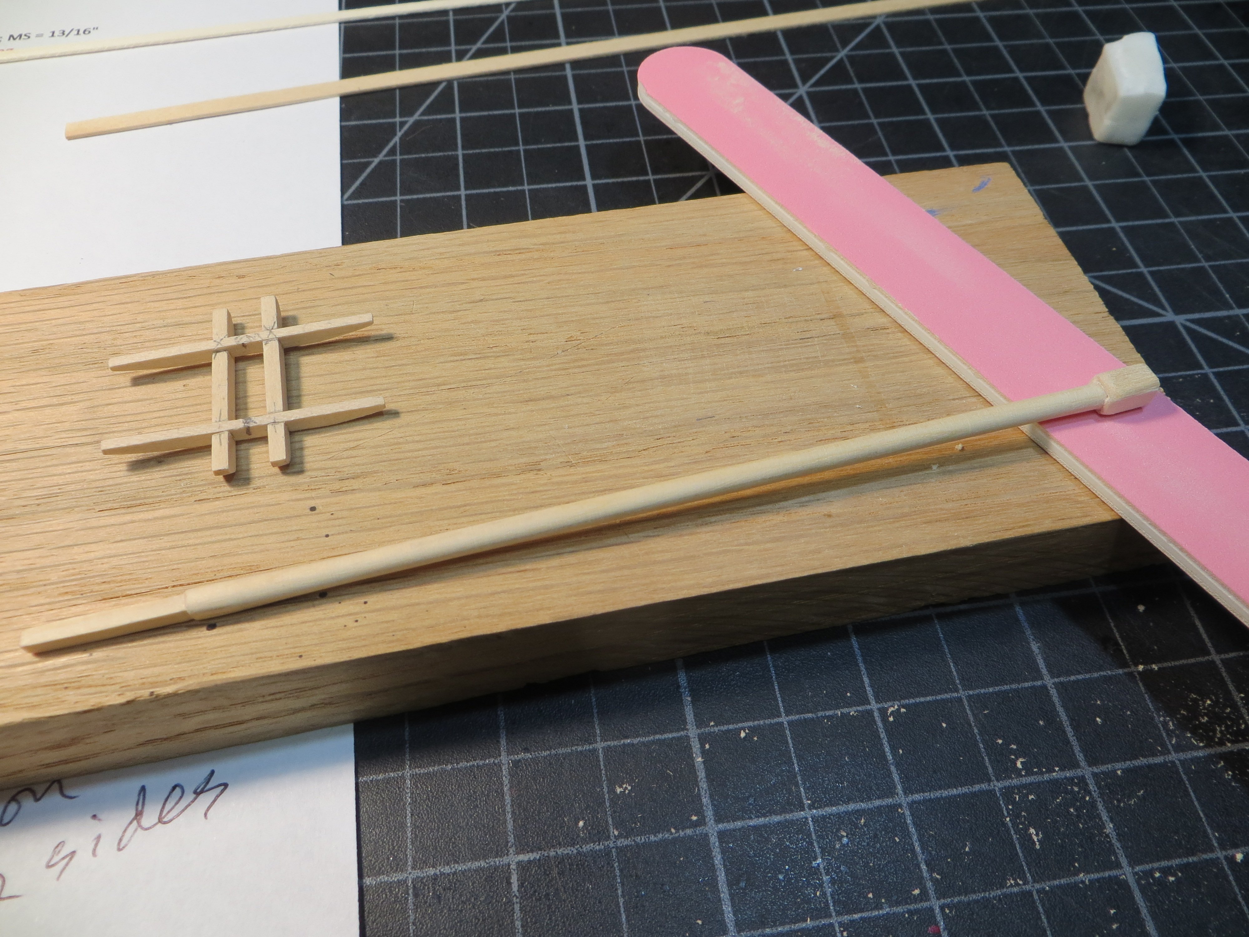
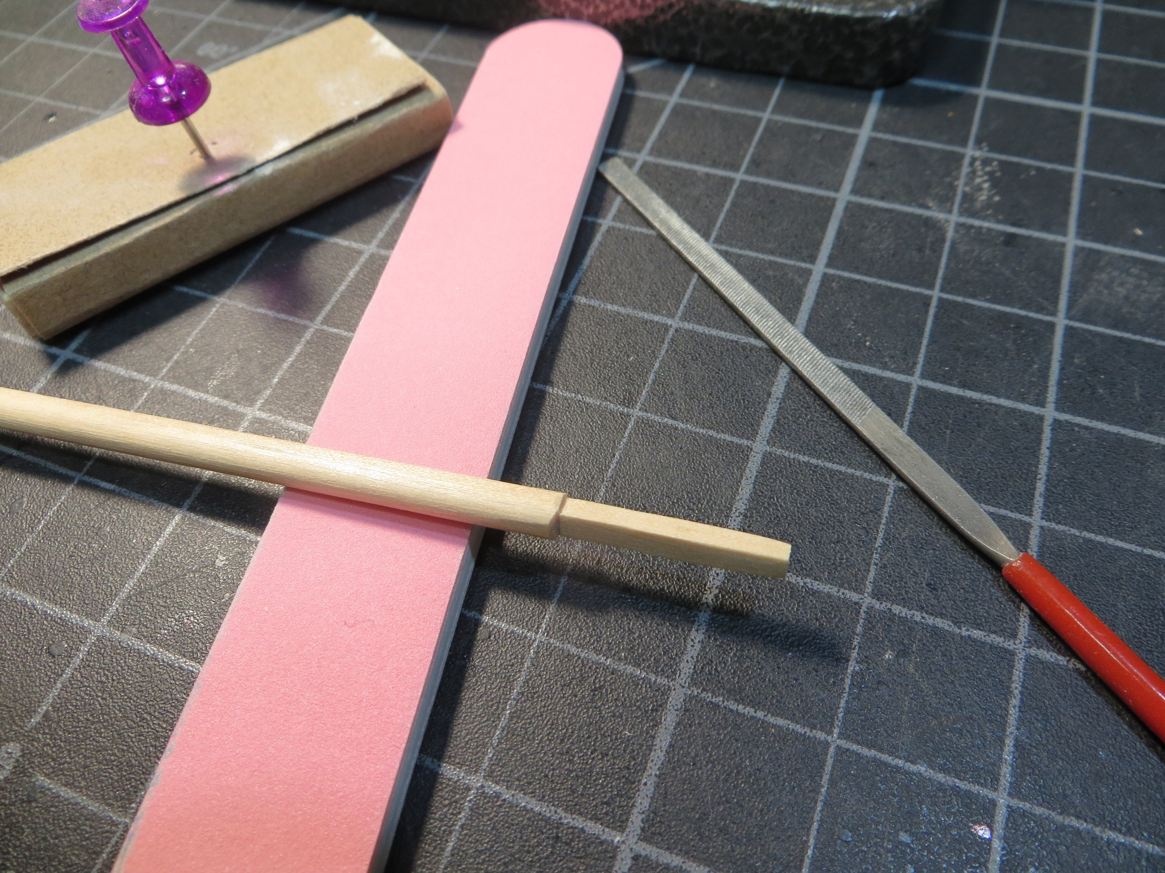
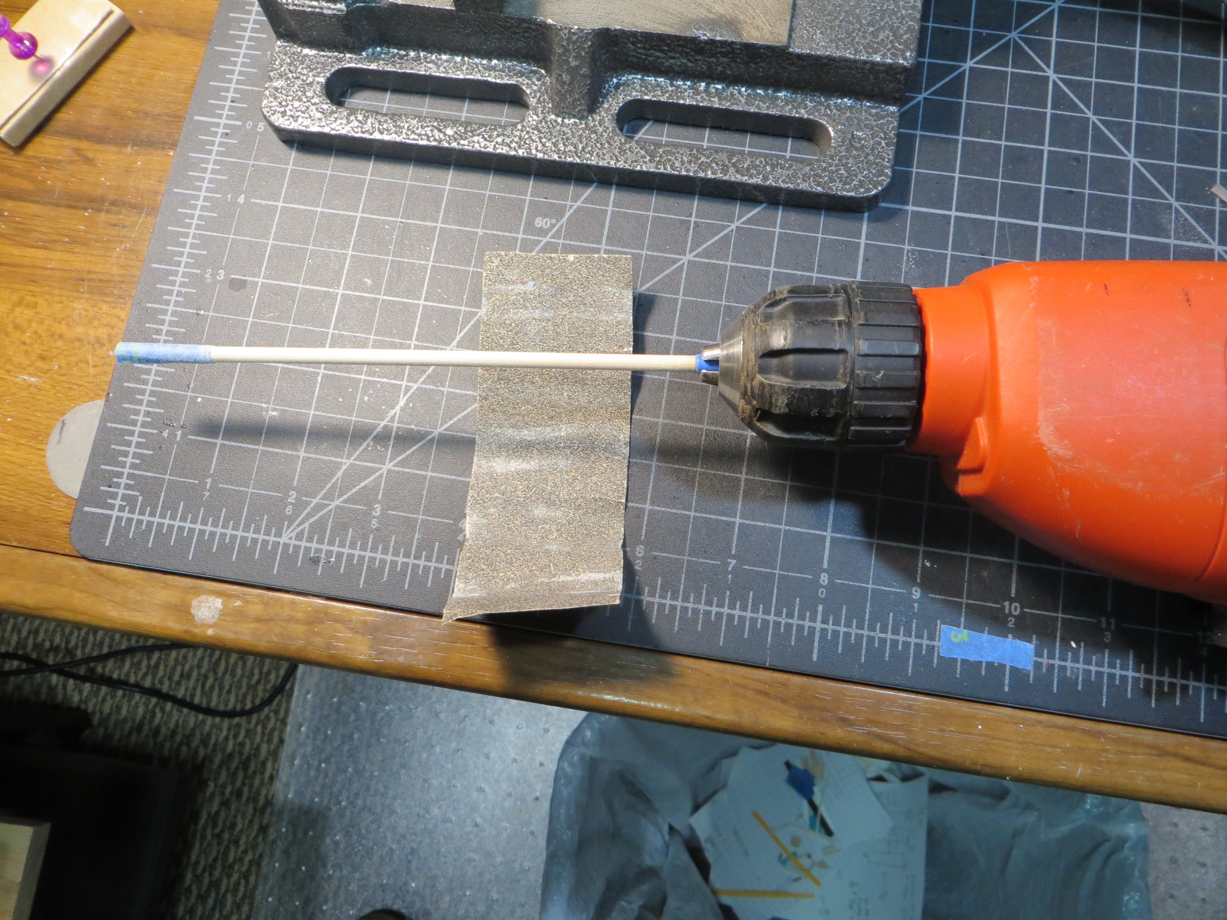
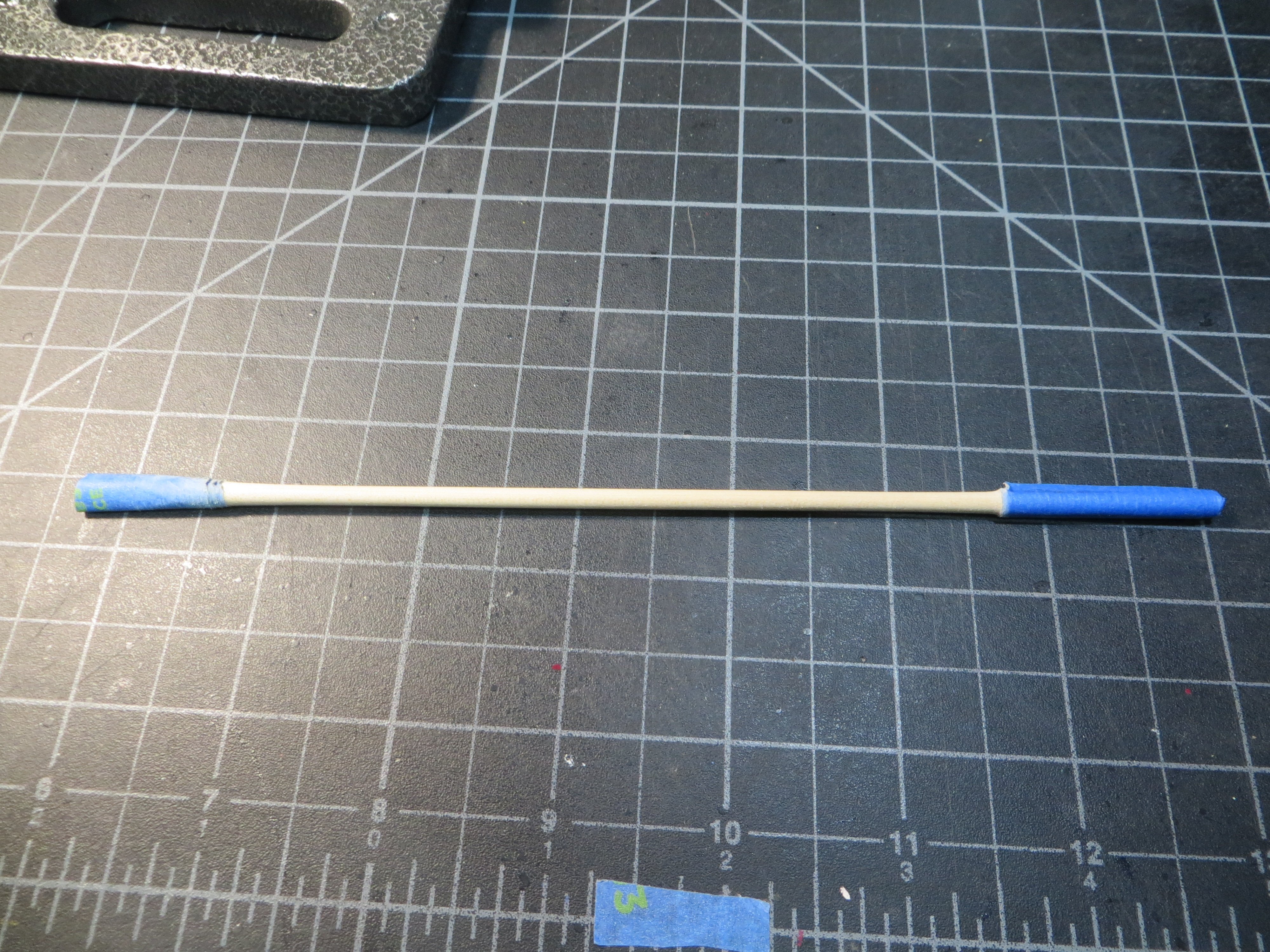
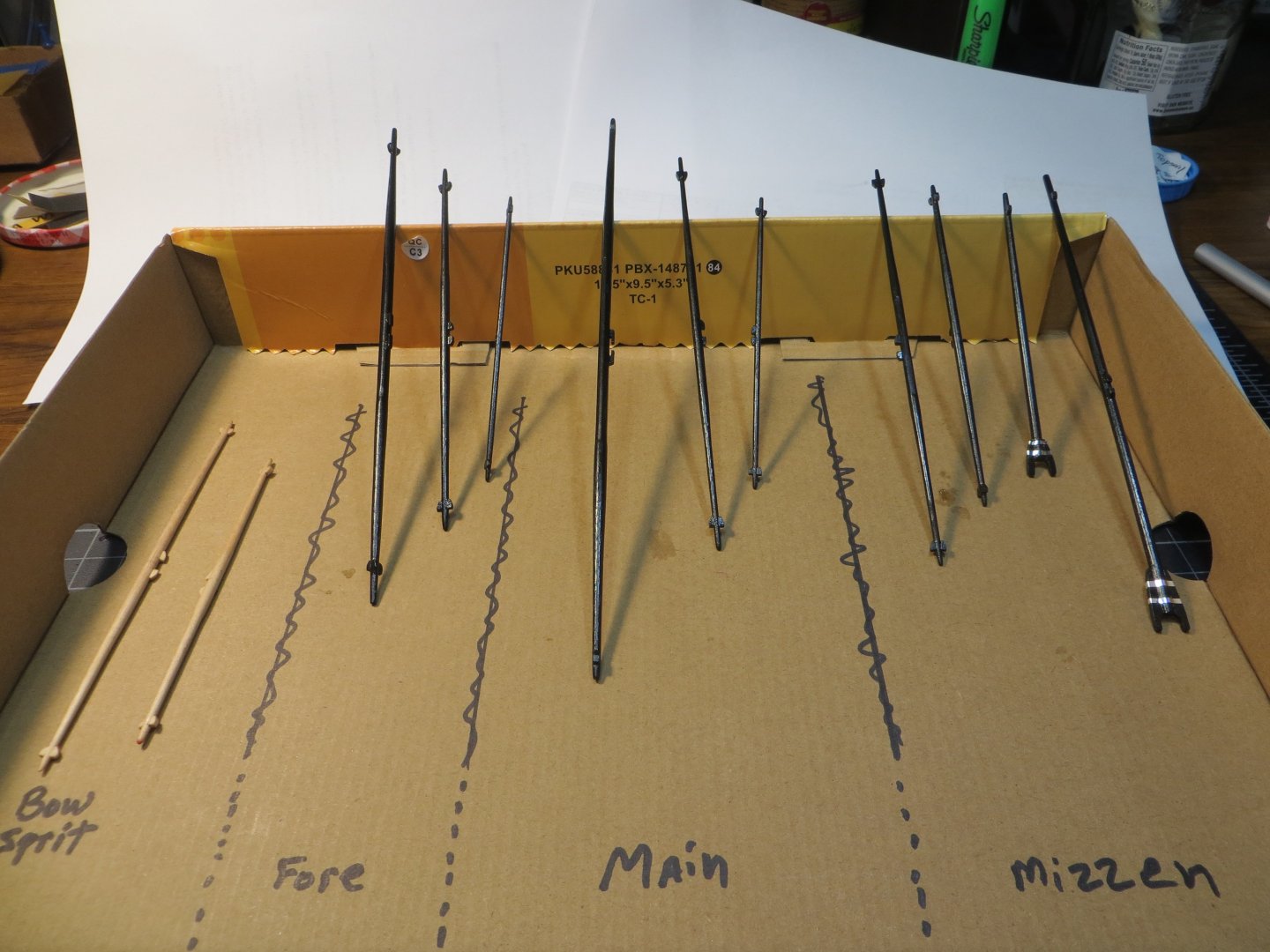
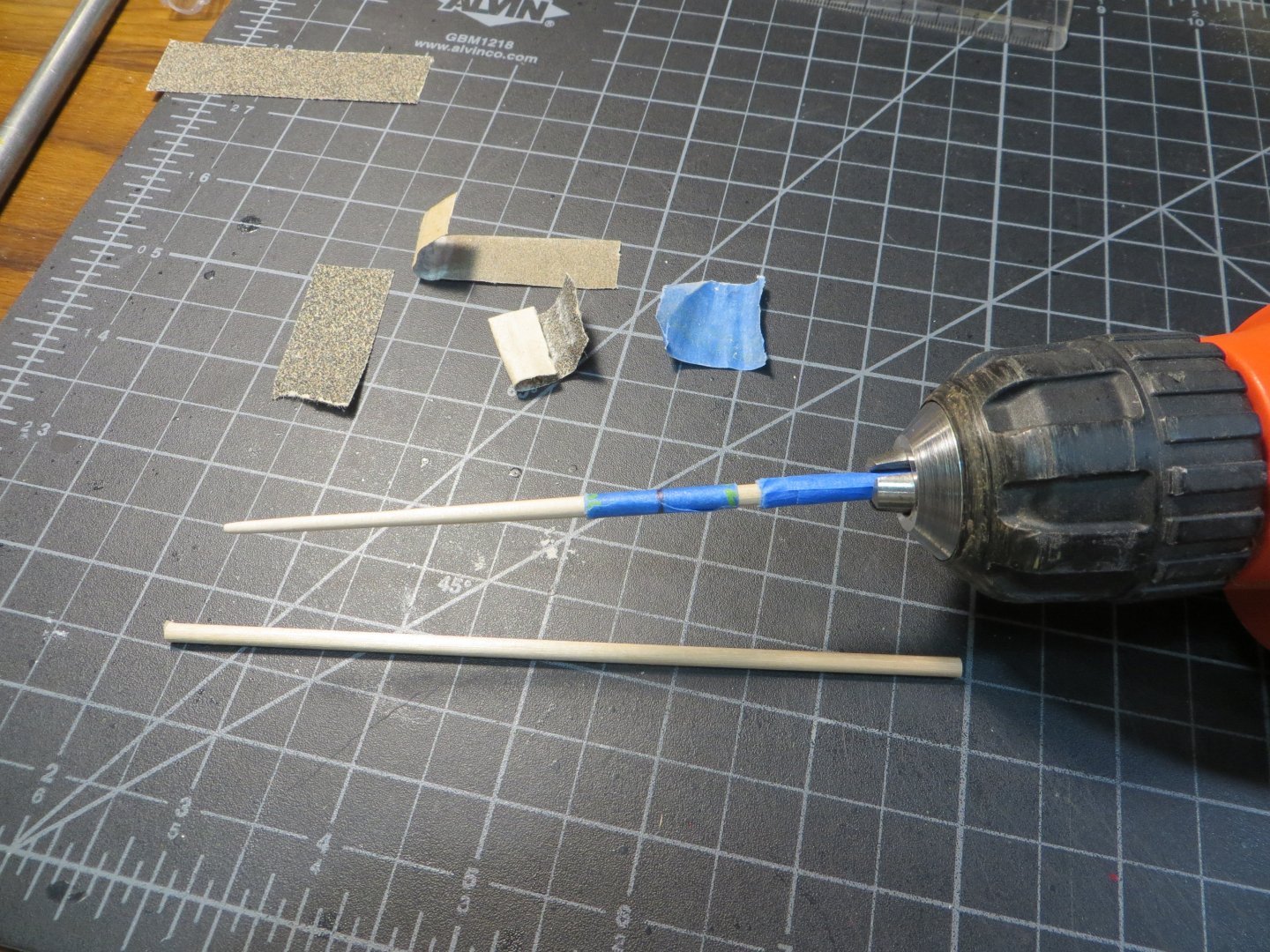
THE YARDARMS There are 12 yardarms that need to be made. Technically two of these are a gaff and a boom for the mizzen spanker sail. But, all of them need to be tapered in some fashion. I had to reconcile some dimensional differences between the Model Shipways plans and the Practicum. I mostly went with the MS dimensions because I am using the dowel sizes that came with the kit. However, the lengths of the various spars seemed to match up pretty well. Here is a list of the 12 yardarms: 1. BOWSPRIT SPRITSAIL YARD 2. BOWSPRIT SPRITSAIL TOPSAIL YARD 3. FORE YARD 4. FORE TOPSAIL YARD 5. FORE TOPGALLANT YARD 6. MAIN YARD 7. MAIN TOPSAIL YARD 8. MAIN TOPGALLANT YARD 9. MIZZEN CROSSJACK YARD 10. MIZZEN TOPSAIL YARD 11. SPANKER GAFF 12. SPANKER BOOM This post will cover the tapering of the yardarms/spars. This was tedious work and took me close to a month, so I’m anxious to get something posted! I still have to cut an octagon shape in the middle of 3 of the yardarms. Also, chocks and sling cleats need to be carved and attached. I’ll cover these steps for my next post. The first thing I did was to create a spreadsheet to organize all the dimensions and sizes for the 12 spars. I took a picture to show you what this looked like. I made a full-scale sketch of the tapered end of each yard before I started. This drawing laid out the taper at various distances from the end of the yardarm. These came from the MS blueprint plans using my digital caliper. I did all of the 1/8” diameter yards first, then the 5/64 and finally 5/32. Most of them are 1/8”. Having just completed the bowsprit, I decided to start with the Spritsail Yard. I used the following technique for all twelve. For the gaff & boom only one end had to be tapered. Preparation Steps a. For the Spritsail Yard, I used a 1/8” dowel; 5-1/2” long; Tapered to 1/16” on each end b. Cut the dowel to the required length & mark the center line c. The middle of each yard needs to be at the full diameter. Cover the center with 1” wide blue masking tape. I marked a line down the center of the blue tape so I could see the CL. d. Make a mark on each side of the centerline that shows where the end of the full diameter ends. Wrap another piece of tape to protect this area from sanding. e. Cover the drill end of the dowel with another thicker layer of the 2” wide tape to protect the dowel while it is locked in the drill chock. This is especially important when it’s time to insert the tapered end in the drill. I had one accident where I snapped the thinned yardarm! Sanding Steps f. I found that when I run the sandpaper evenly across the spinning wood dowel, it all comes out at the same diameter. So, start with the largest diameter taper and sand from the blue tape to the end. When this measurement is achieved, mark the next point on the dowel and sand until you achieve this number from the mark to the end. Move from the center to the end in increasingly narrower sections until the taper is completed. I would constantly stop to clean the sawdust off the sandpaper and check the diameter using the caliper while holding the end of the dowel up to my sketch. g. So, for the Spritsail Yard I used the drill to sand the exposed area all to 7/64 first. Then mark where to stop with 7/64 and sand the next section down to 3/32. Then finish the end down to 1/16” at the tip. h. When done I removed the blue tape from that end and smoothed/blended out this half with 220 grit paper. i. Now flip the yardarm around and repeat the steps on the other side One dowel cut and another wrapped with masking tape and with one side tapered Yardarm in the drill during tapering Tapering finished on this one Here are all the yardarms labelled after sanding As I said, just a couple of more steps to complete the yardarms. Then it will be time to start rigging!! My Chicago Bears might be good this season. I wouldn’t even mind if that interferes with shipbuilding!! Thanks for looking in! Ed


-
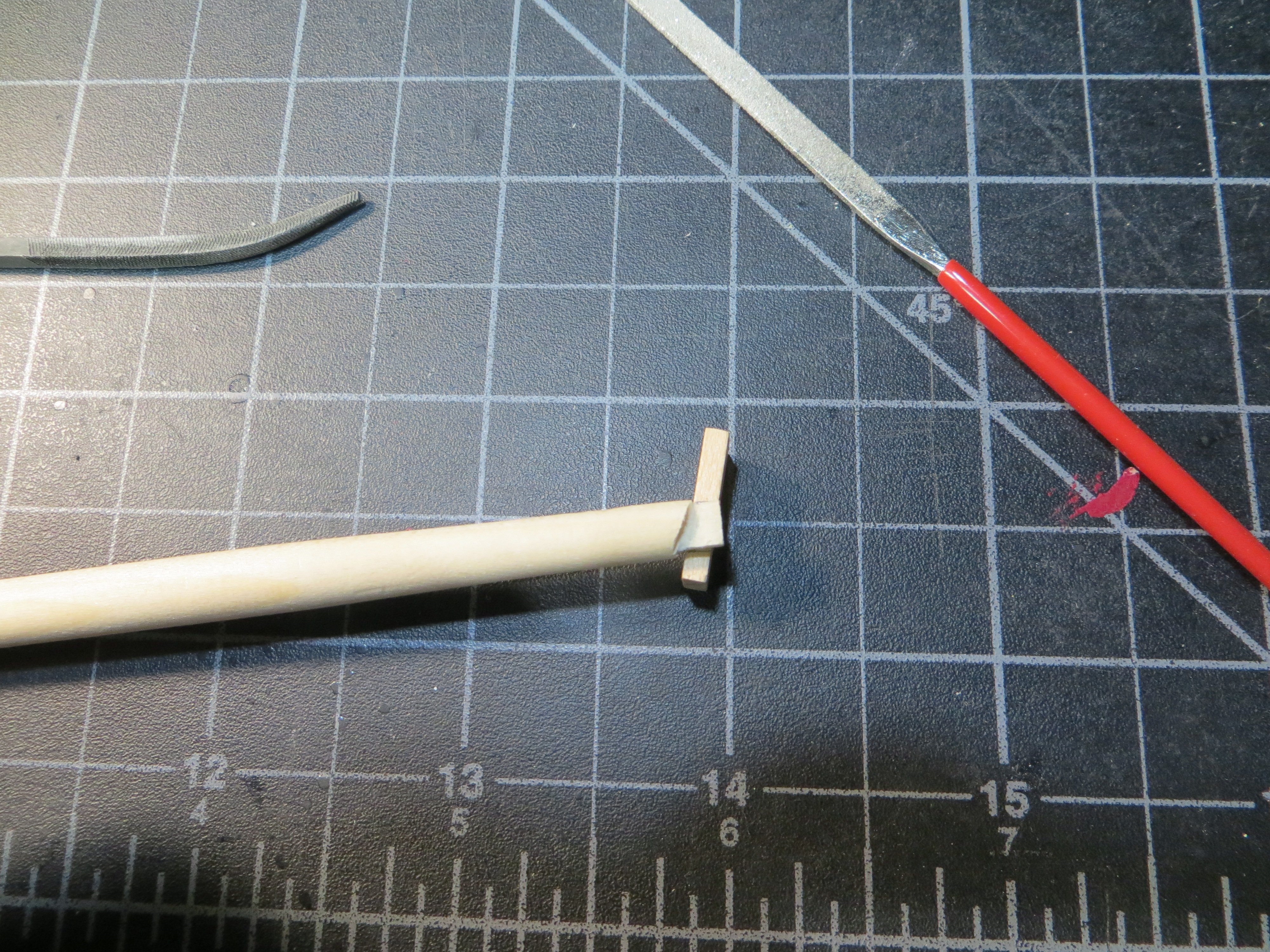
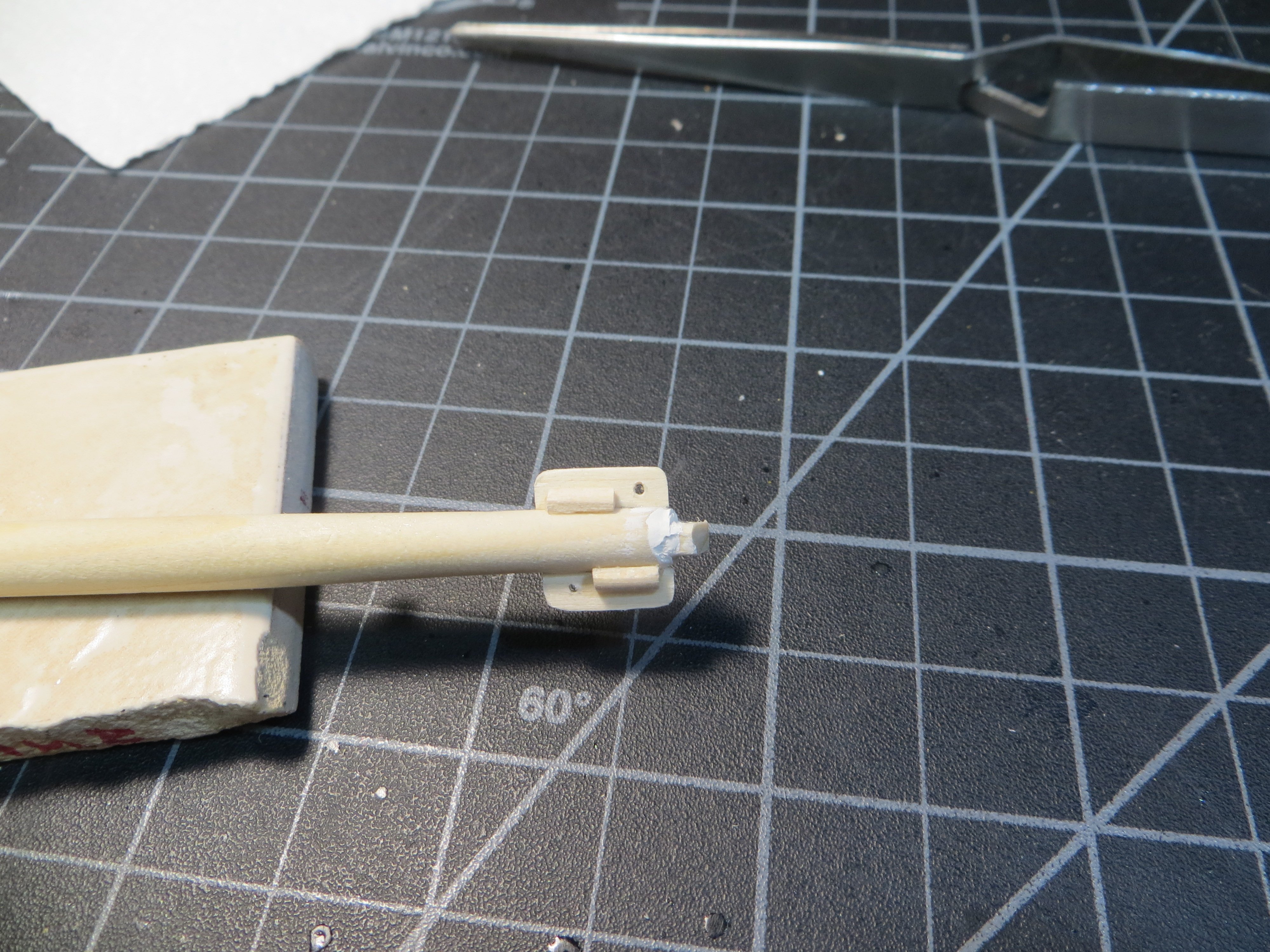
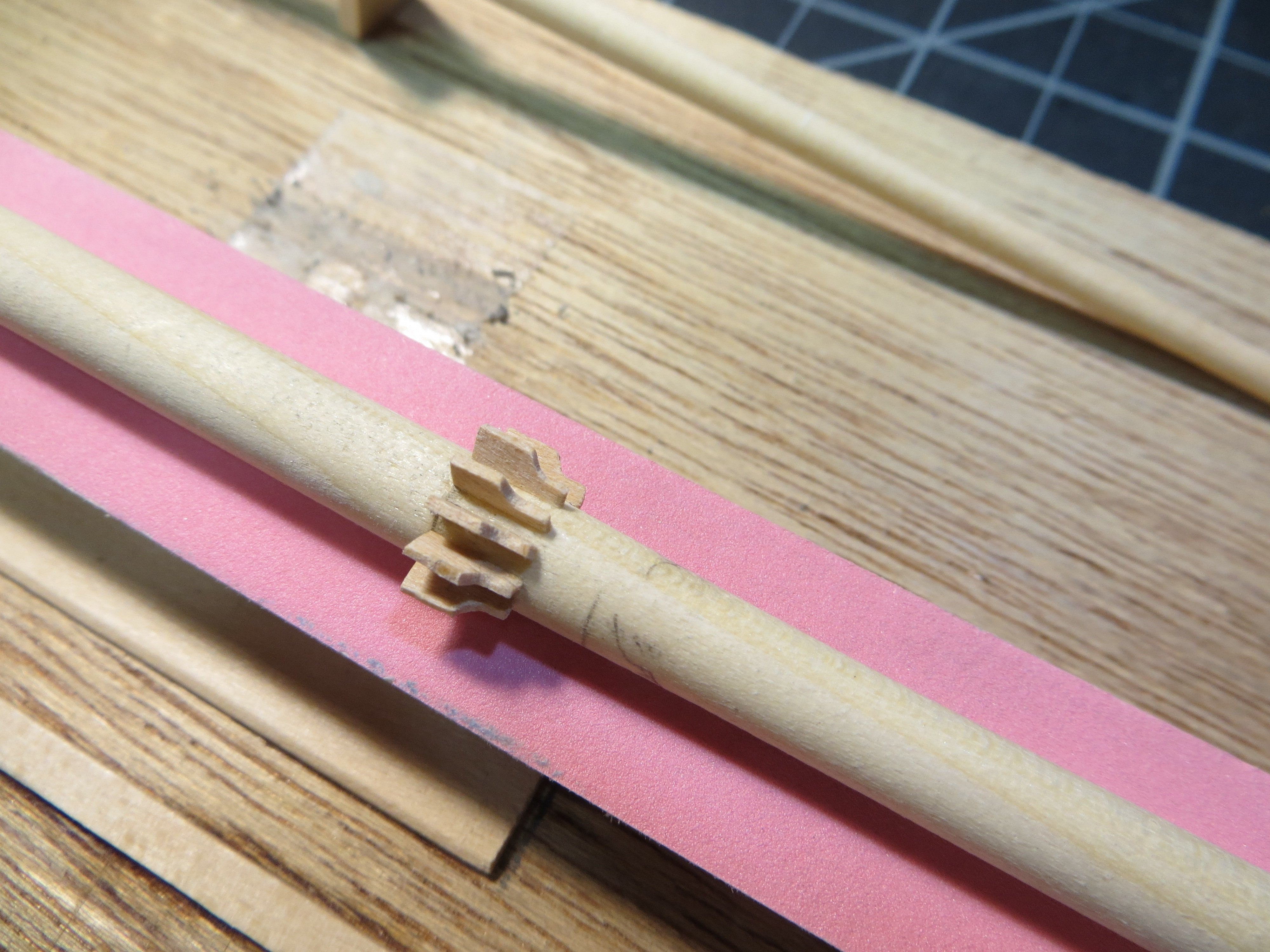
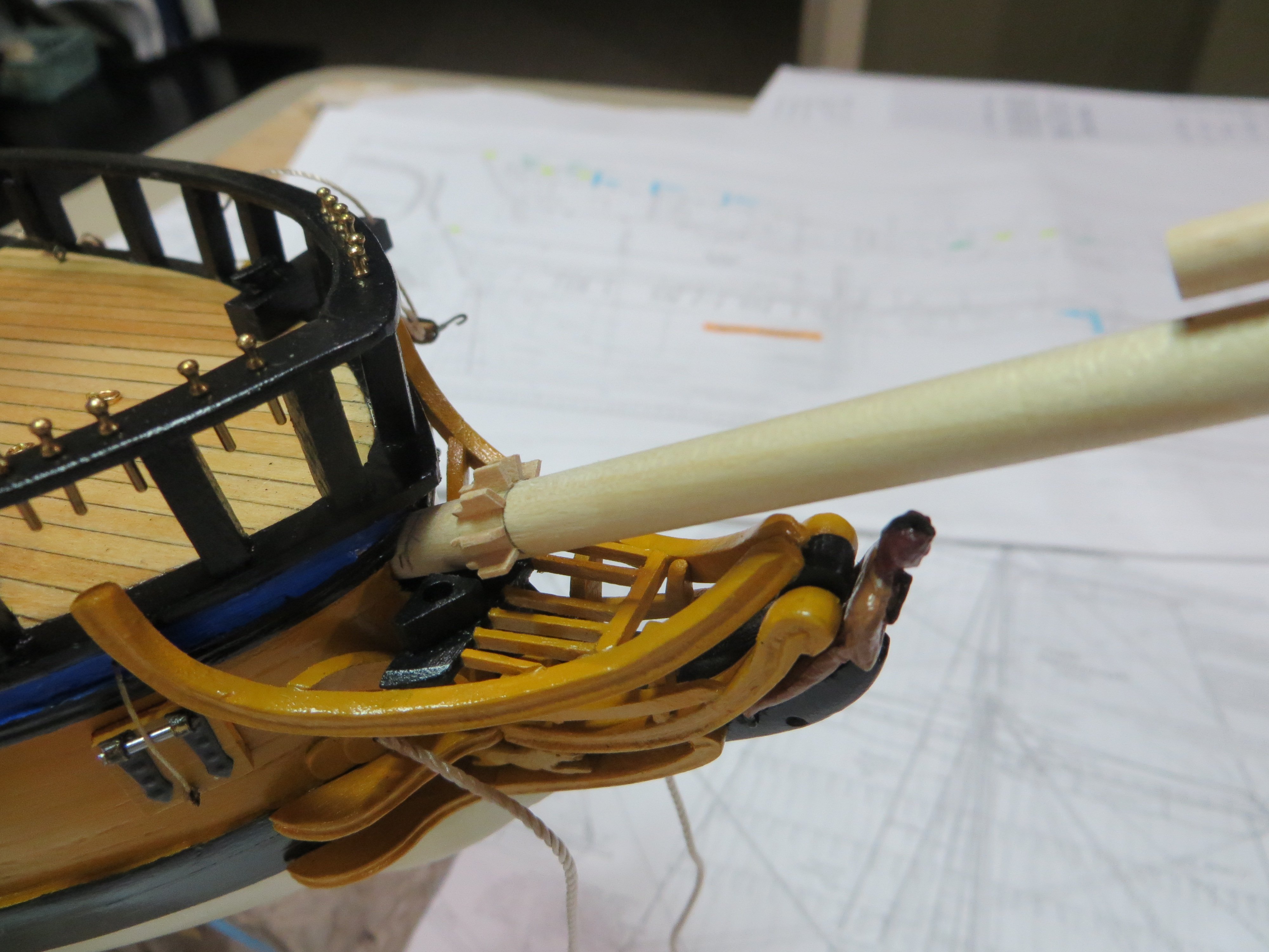
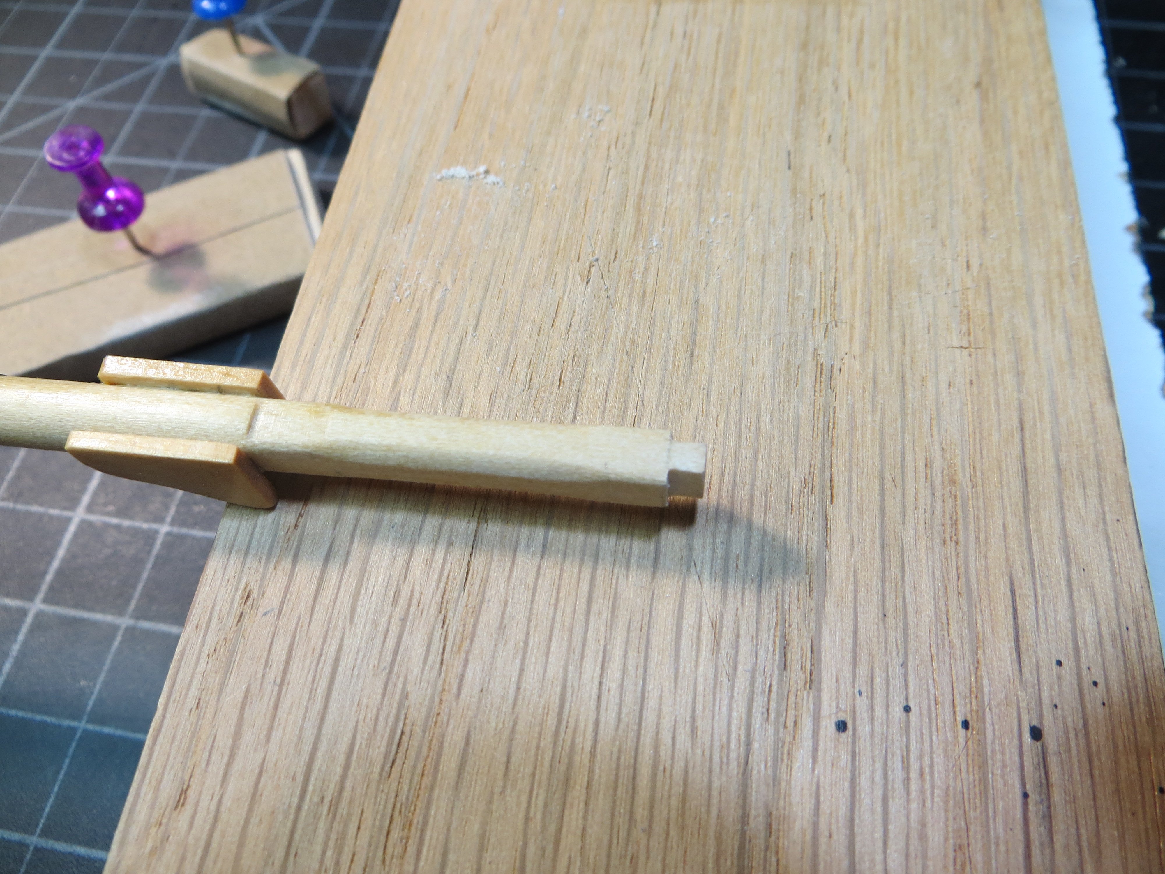
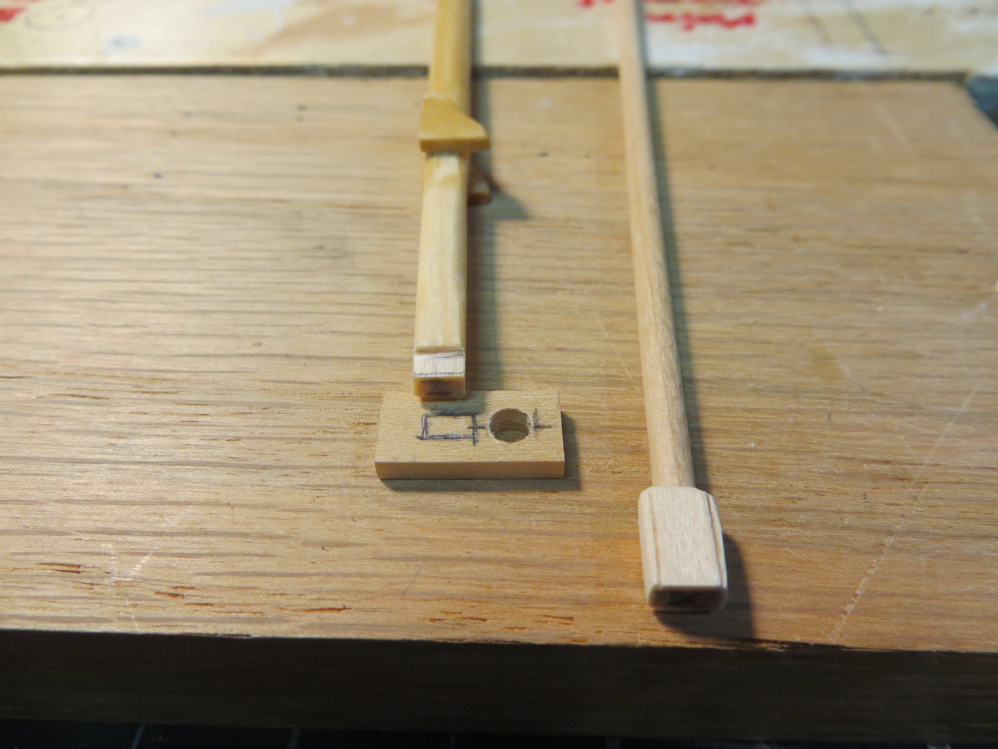
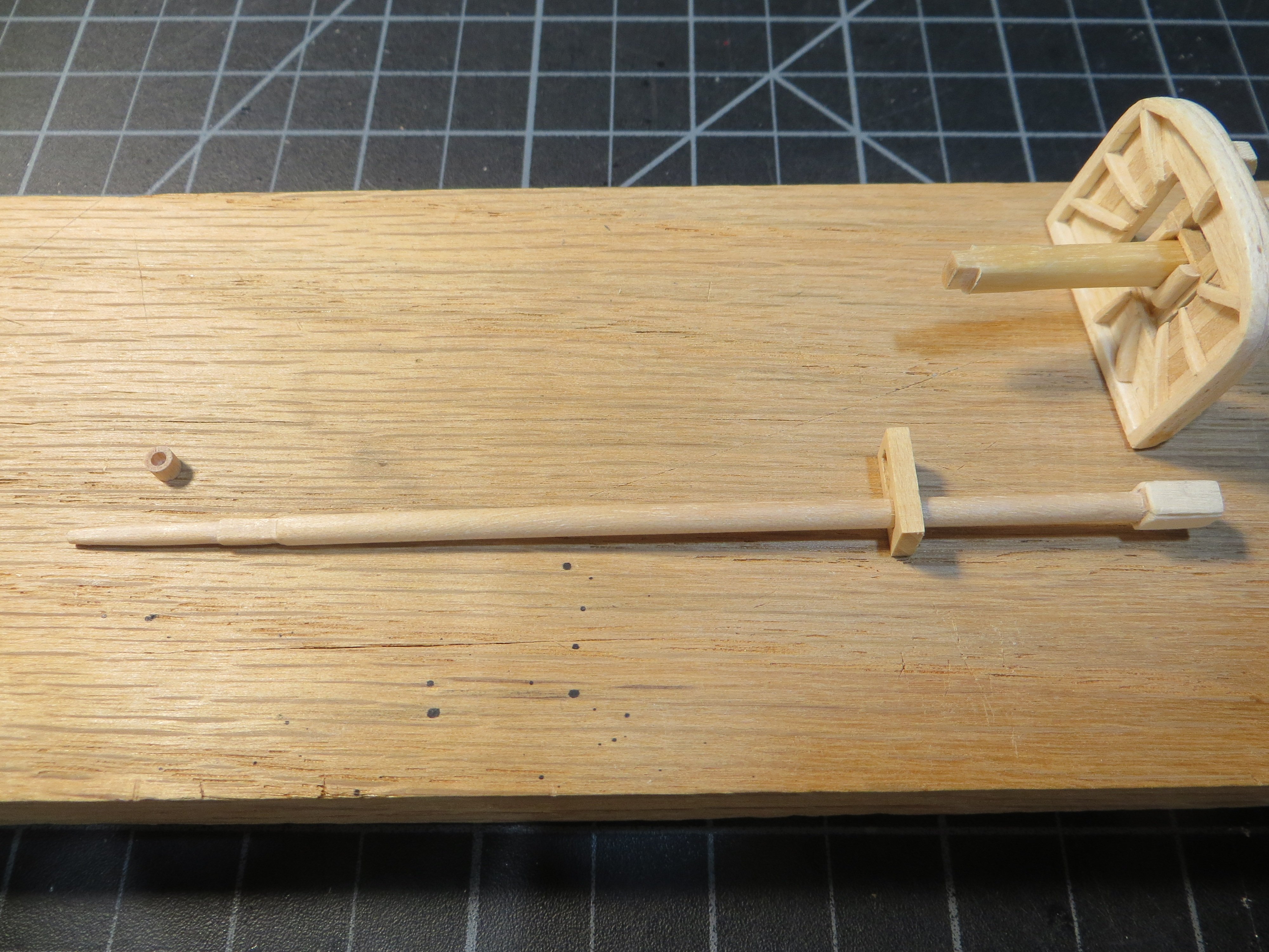
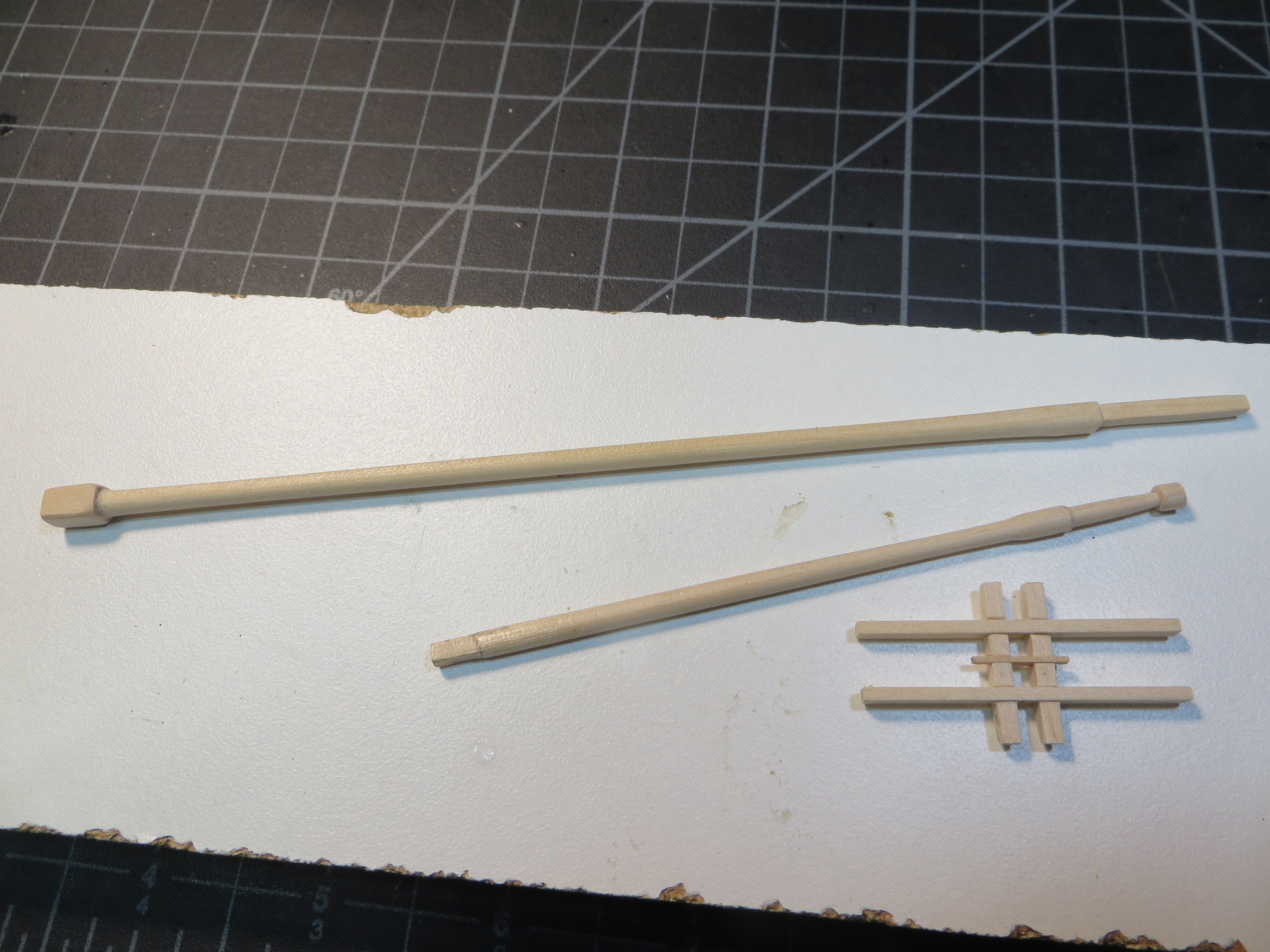
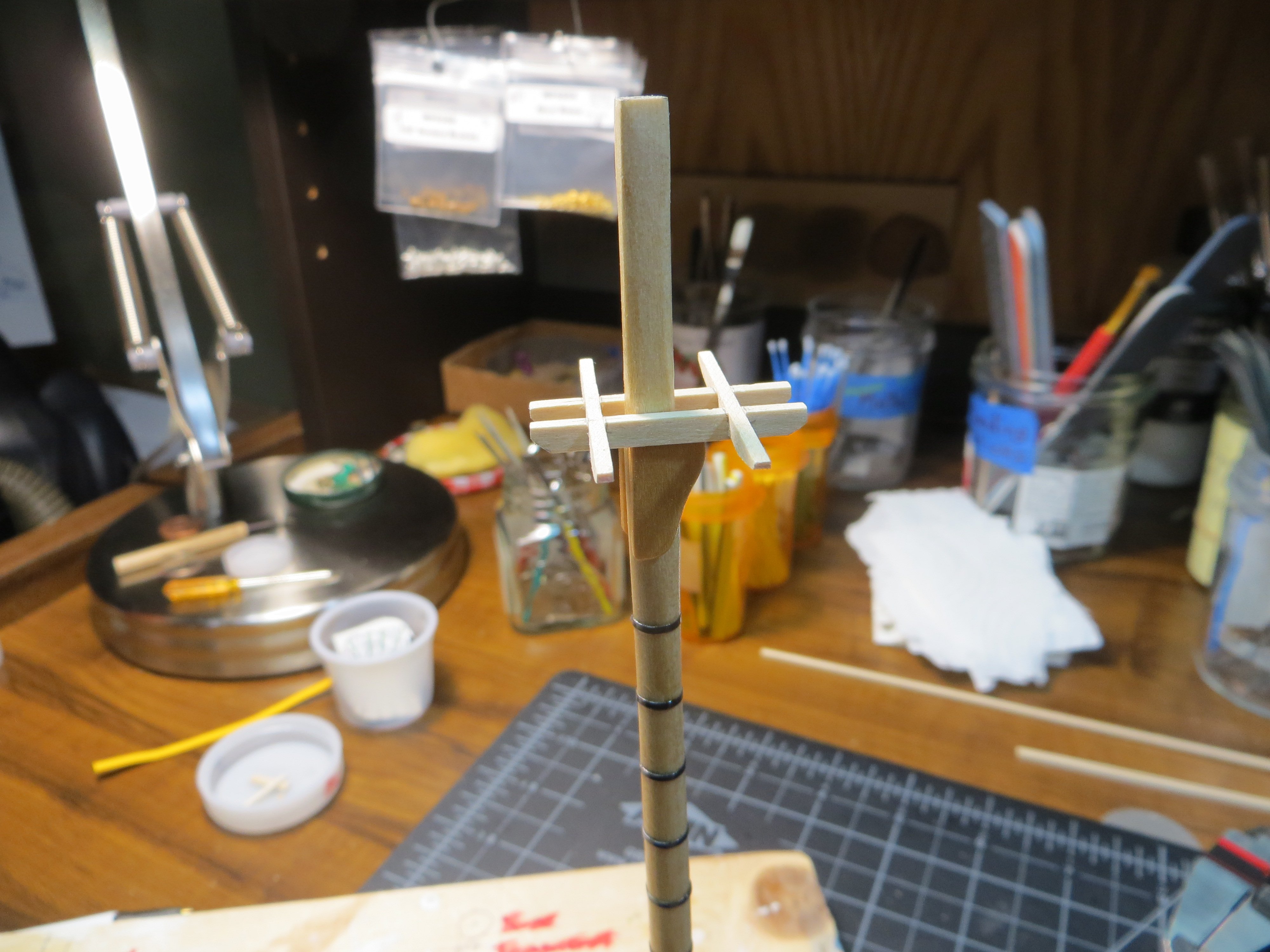
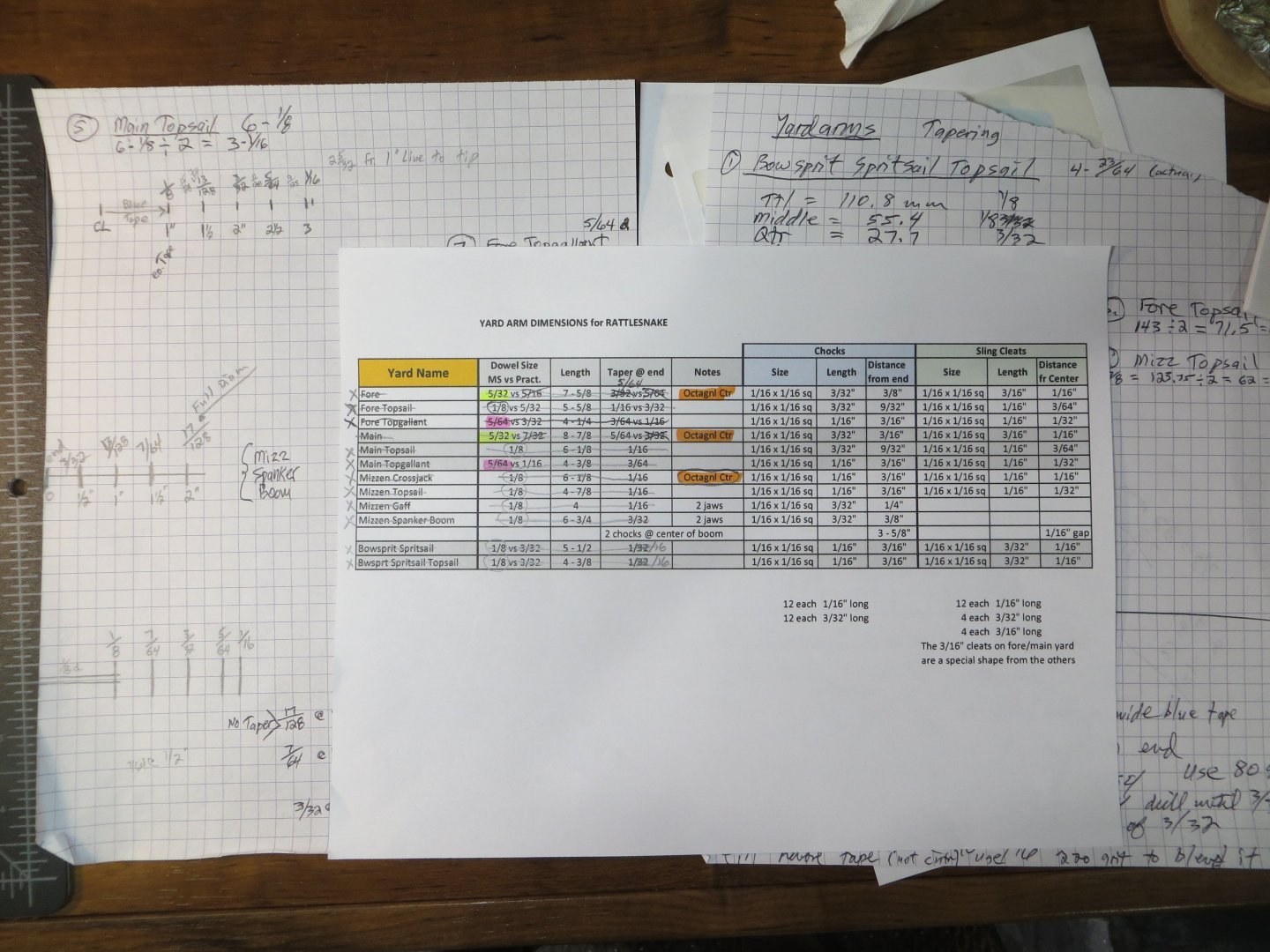
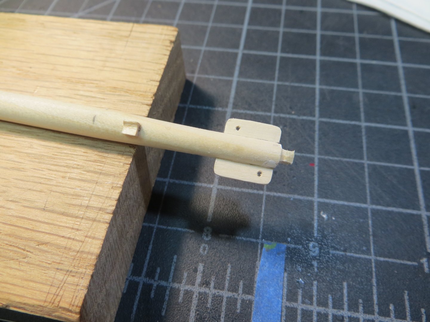
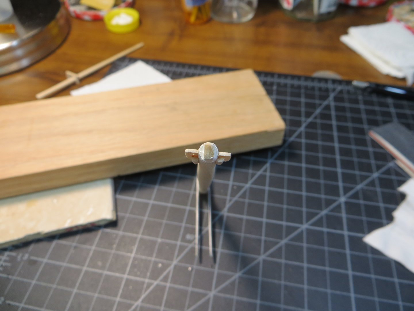
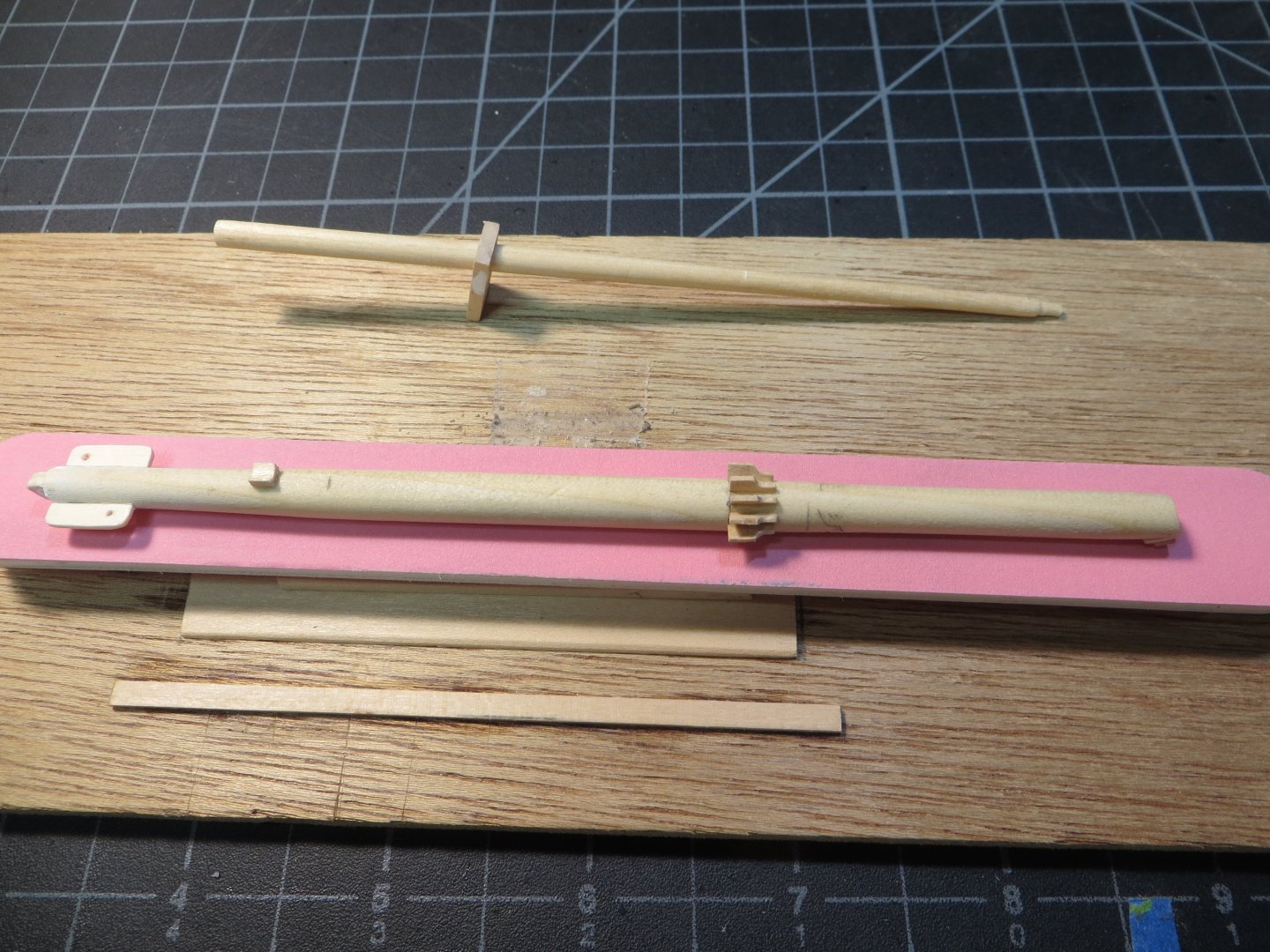
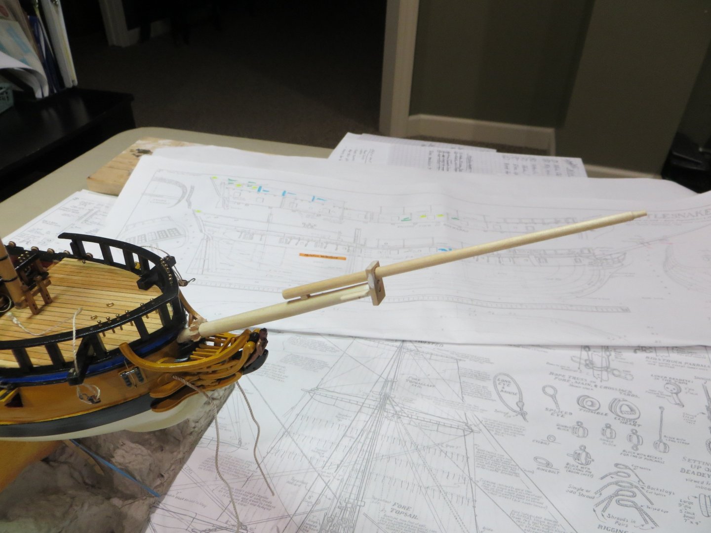
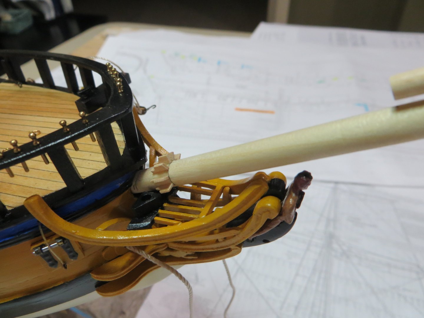
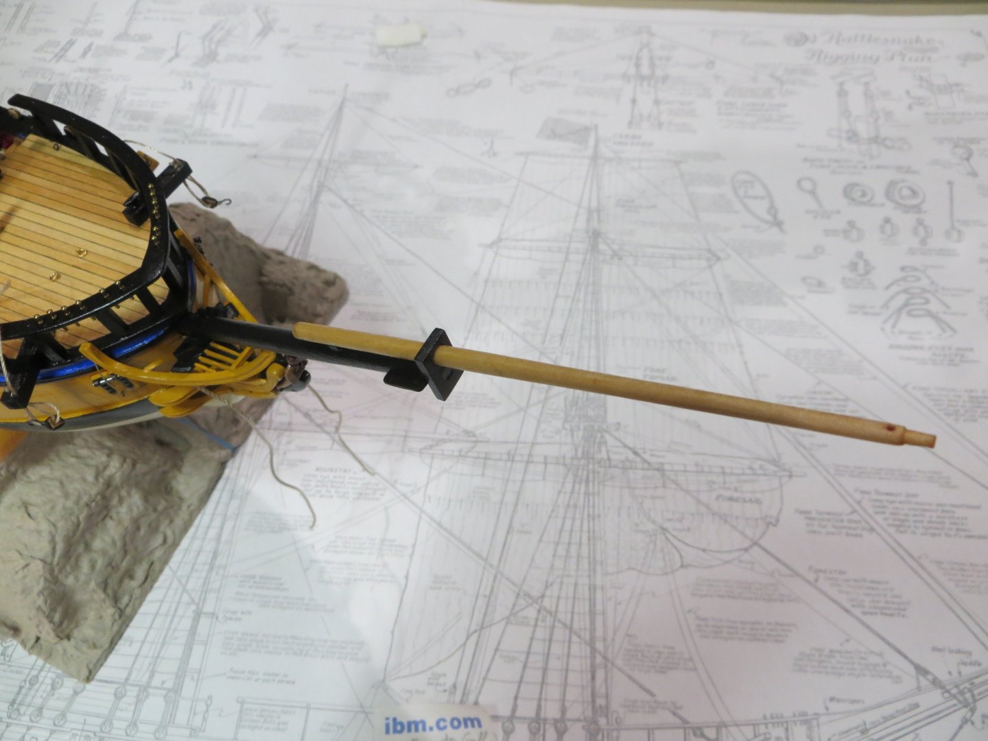
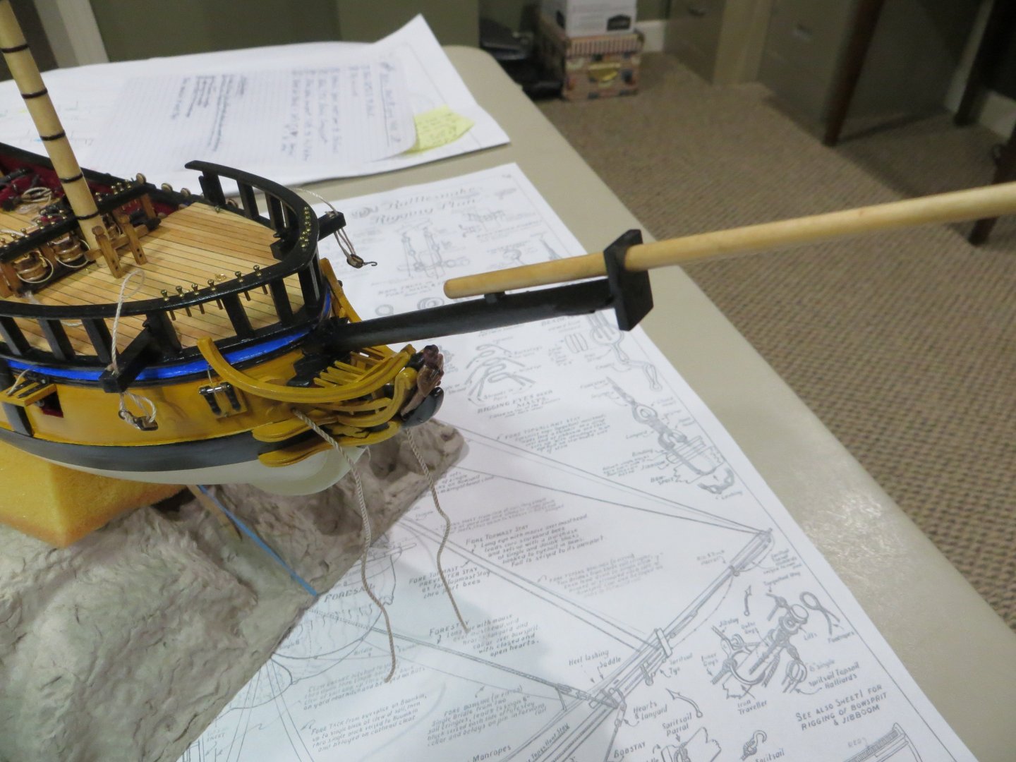
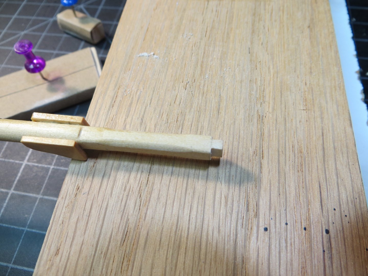
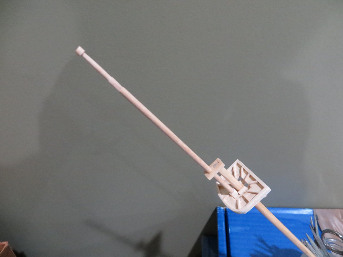
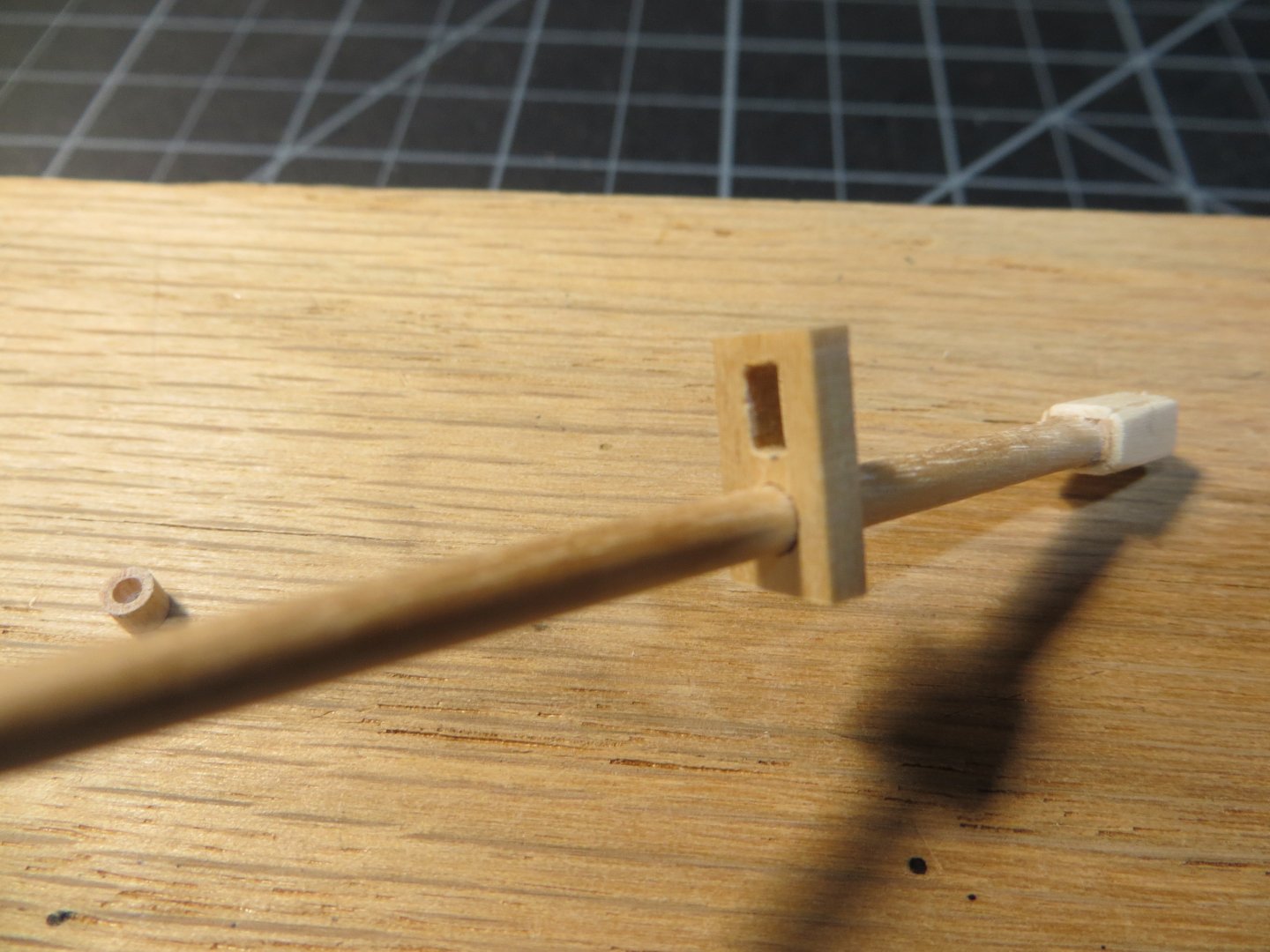
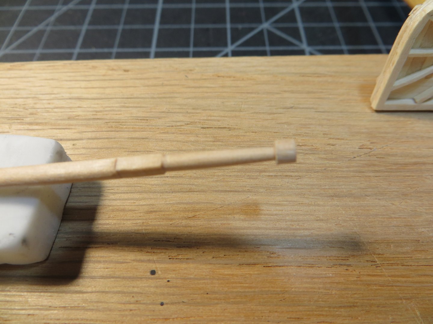
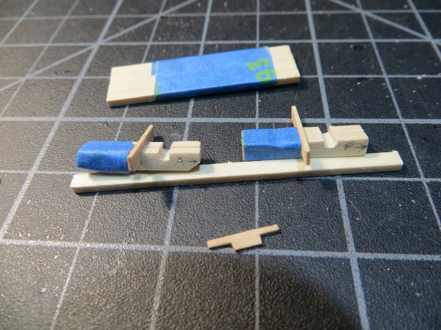
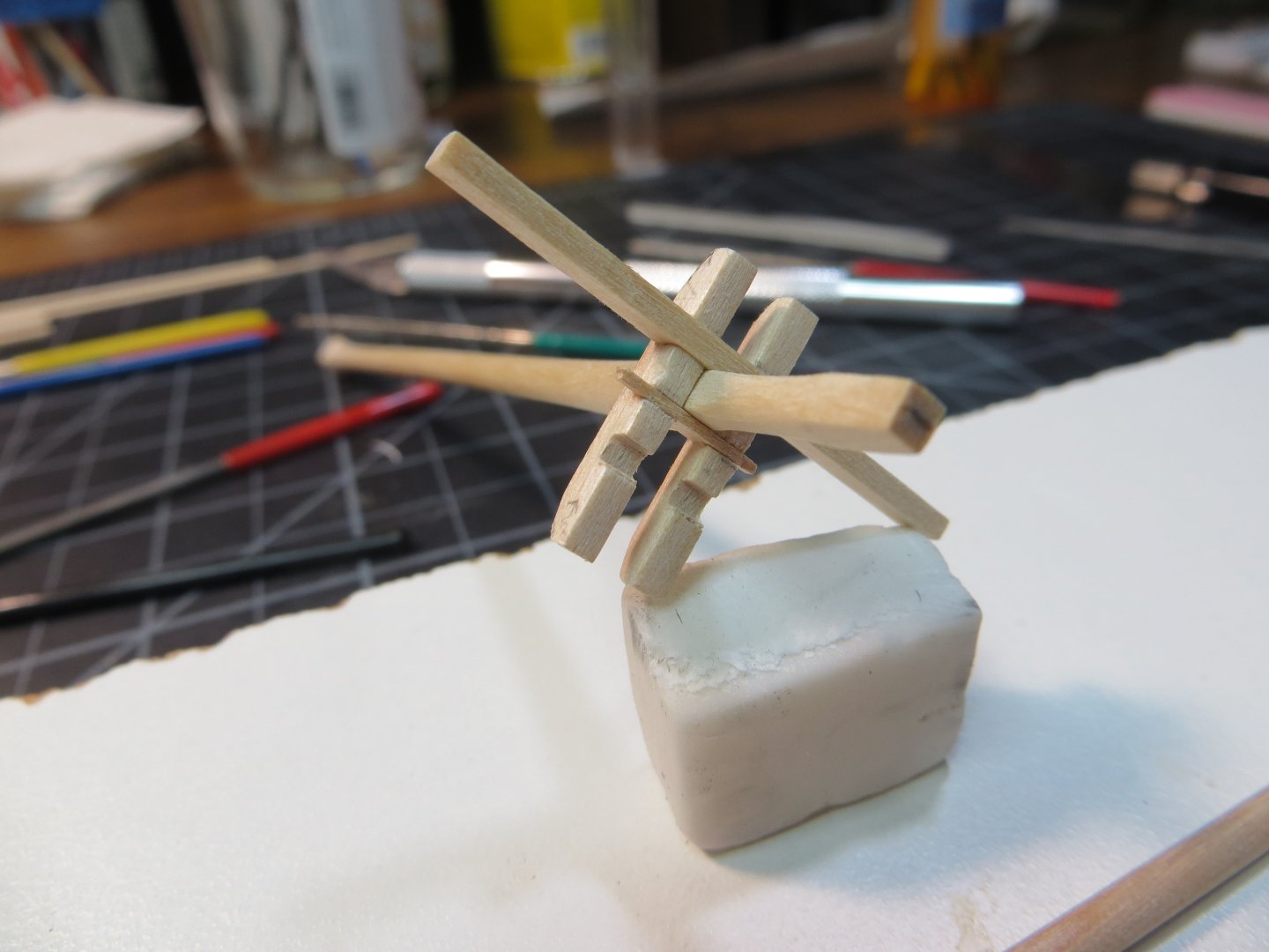
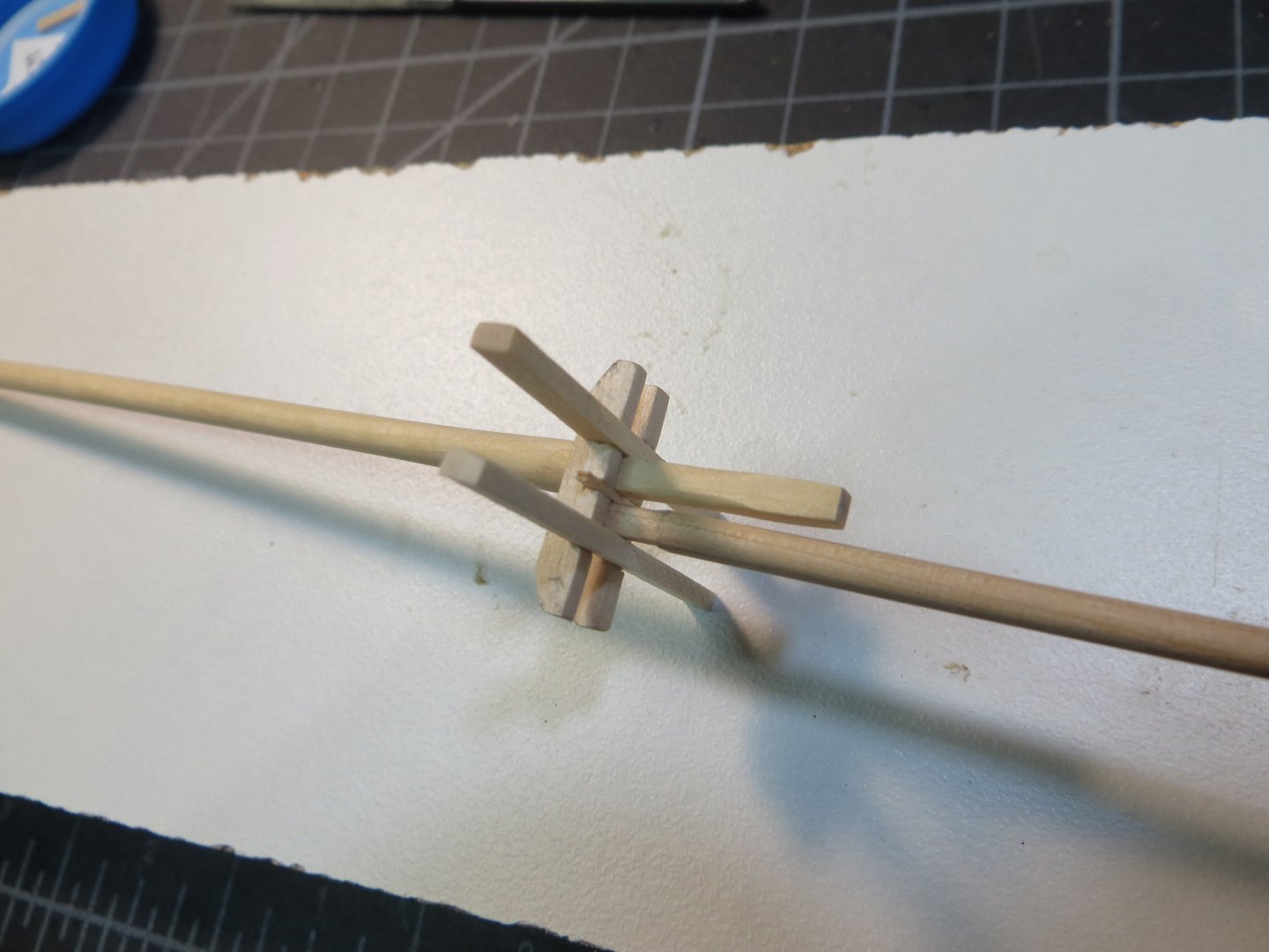
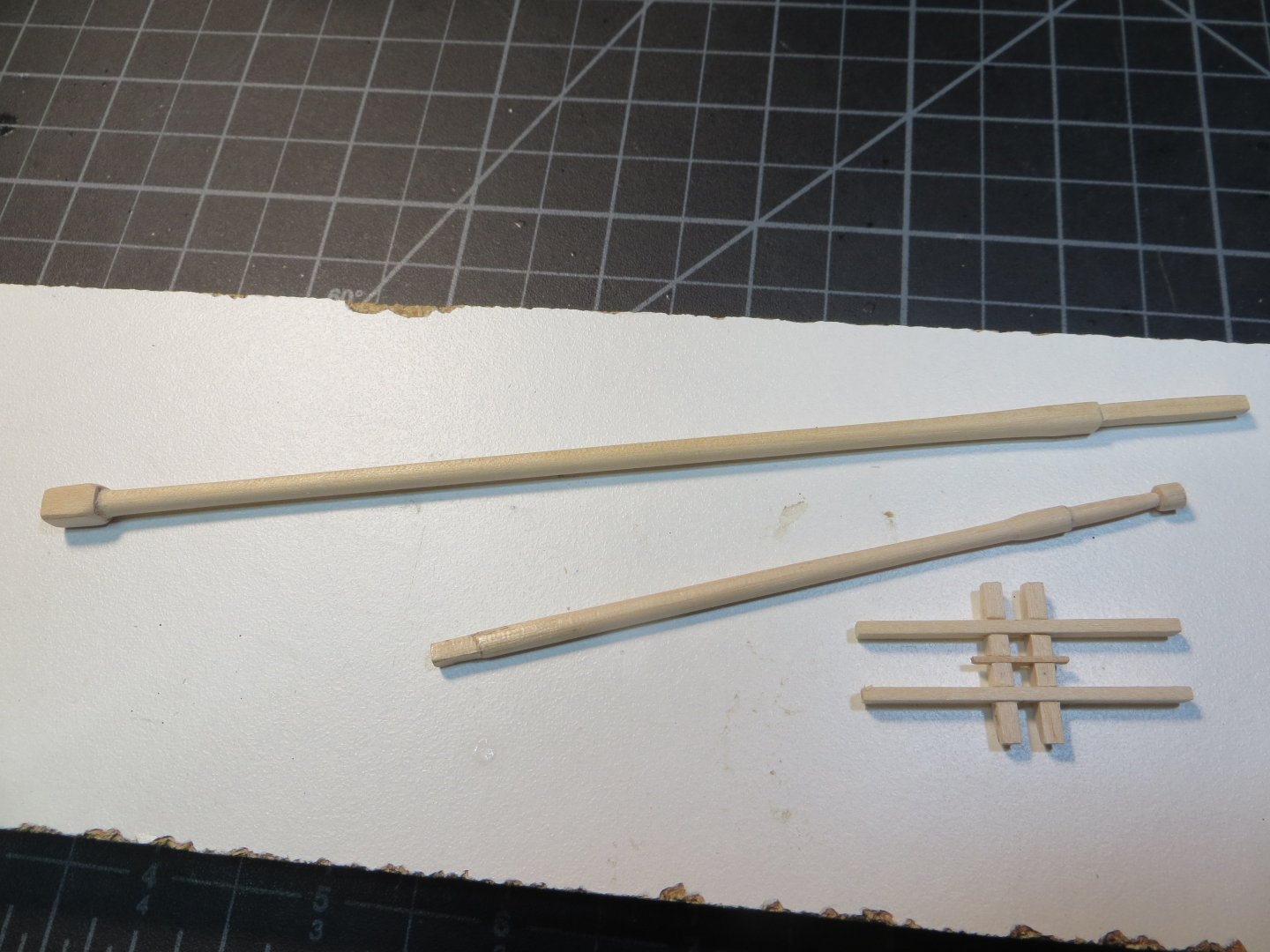
THE BOWSPRIT Work on the Rattlesnake is moving slowly this summer. Slow, but sure, progress is being made! The Bowsprit is made with two wood dowels. The bowsprit piece is thicker at ¼” in diameter. According to the practicum the jib boom is made with a 5/32” dowel. According to Model Shipways it should be 1/8”. I went with 5/32”. They are joined with a cap similar to the lower masts. Another difference is the length of the ¼” bowsprit section. Per the practicum the bowsprit is 5-1/16” long. However, per JSGerson, whom I’ve been following, the correct length is 5-7/8”. According to my measurements, there should be 4” from outside the hole in the bow to the end of the cap (so, including the tenon). On my model, I needed a total length of 5-5/8” to leave 4” outside the bow of the ship. The end that sits on the main deck must be sanded flat. On my ship this caused the bowsprit to have a little too steep of an angle. I added some scrap wood to raise up the base of the bowsprit off the deck. The outer third of the bowsprit piece is tapered to 3/16” diameter at the end. I used my power drill technique to achieve the correct taper. A rectangular tenon was cut on the outside end. This fits into a hole that is cut into the cap. The tenon and the cap must be cut at an angle that is perpendicular to the waterline. The cap is 3/32” thick x 9/16” long x 1/8” wide. I just eyeballed the angle for the tenon from a dry fit position on the ship. I cut it first. Then I transferred the top and bottom marks of the tenon to the cap. Drill a pilot hole in the cap for the bowsprit tenon and then enlarge and square up the hole using mini-files. Here is a picture of the tenon laid over the cap to find & mark the angle Next, I made the jib boom from a 5/32” dowel that is 4-3/4” long. Taper the diameter to 1/16” at the forward end. The practicum said do not round over the end. Now the hole for the jib boom can be made in the mast cap, at the same angle as the bowsprit. The jib boom fits thru the hole so that 1-1/2” extends aft from the back of the cap. The last 1/8” of the jib boom tip is trimmed down to 1/16” to form a lip for rigging. A hole is drilled just behind this lip for the jib stay to pass through. A small saddle made from 1/16" square boxwood is fitted on top of the bowsprit and the jib boom sits in this saddle. The saddle has a concave surface both on top and the bottom where the bottom matches the curvature of the bowsprit and the top matches the curvature of the jib boom. Sorry, I don’t have pictures during the process for each step. Below are pics of the finished step. The next step is to make a pair of “Bee’s and Bee Blocks”. This is a support on either side of the bowsprit just behind the cap. A hole is drilled in each one through which some fore topmast rigging passes. I have some pictures. The pair of Bee’s on the front end of the bowsprit The Bee Blocks under the Bee’s provide support Head on view of the Bees & their blocks The Gammoning Cleats are the last pieces to be made and installed on the bowsprit at this time. Started by dry fitting the bowsprit to determine where the Gammoning Cleats are to be positioned. This was done by wrapping a single line from the gammoning slot straight up and around the bowsprit and through the gammoning slot again. A pencil line was drawn tracing the rigging line on the bowsprit. Six pieces of 1/32” x 3/32” stock were cut to 7/32” long. These were set up in one of my jigs and the curved shape was cut into the end with a round mini-file. The finished pieces are glued around the top half of the bowsprit. Jig for cutting the shape into the Gammoning Cleats. I cleaned them up with a sanding twig afterward The cleats are glued to the bowsprit Bowsprit with gammoning cleats positioned above the gammoning slot in the ship’s stem The various parts and pieces for the bowsprit have been completed The bowsprit is dry fitted on the ship Views of the bowsprit after painting and staining My next step is to make the yardarms. Lots of sanding to taper the yards! I will use the power drill. Thanks for checking in on my progress!! Ed


-
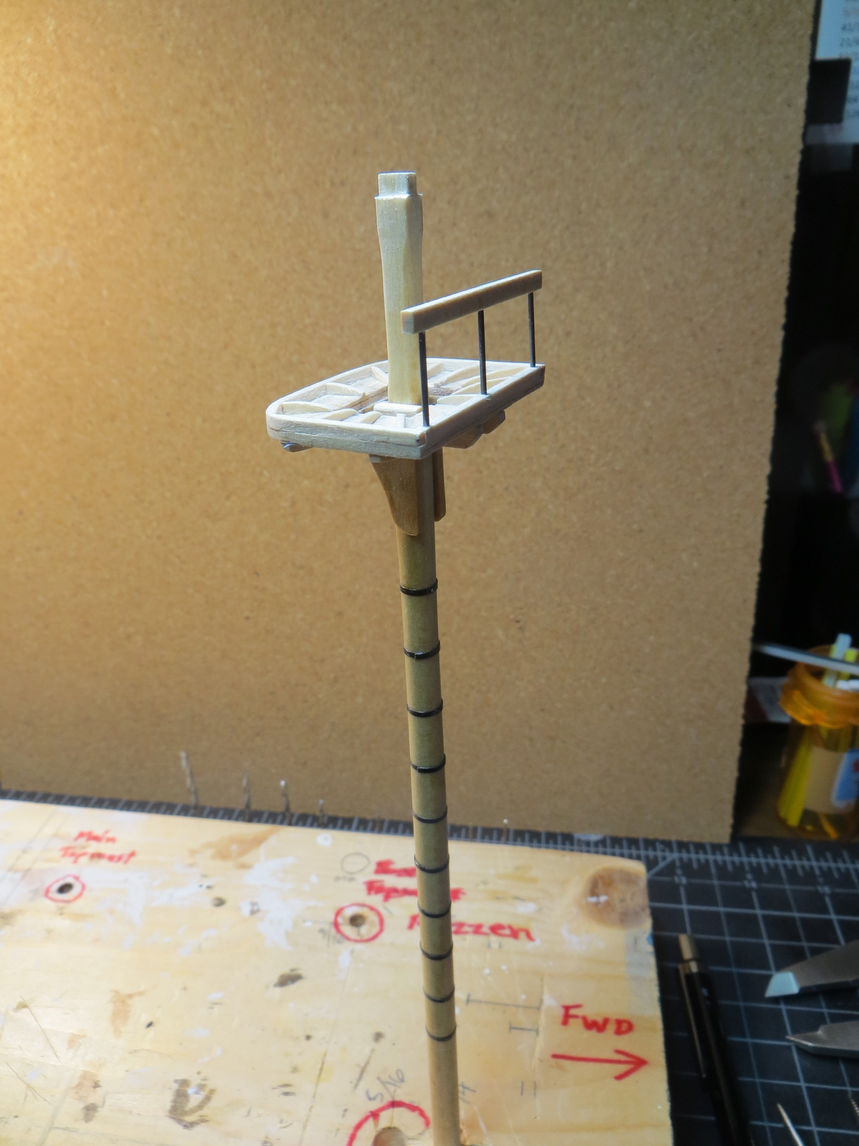
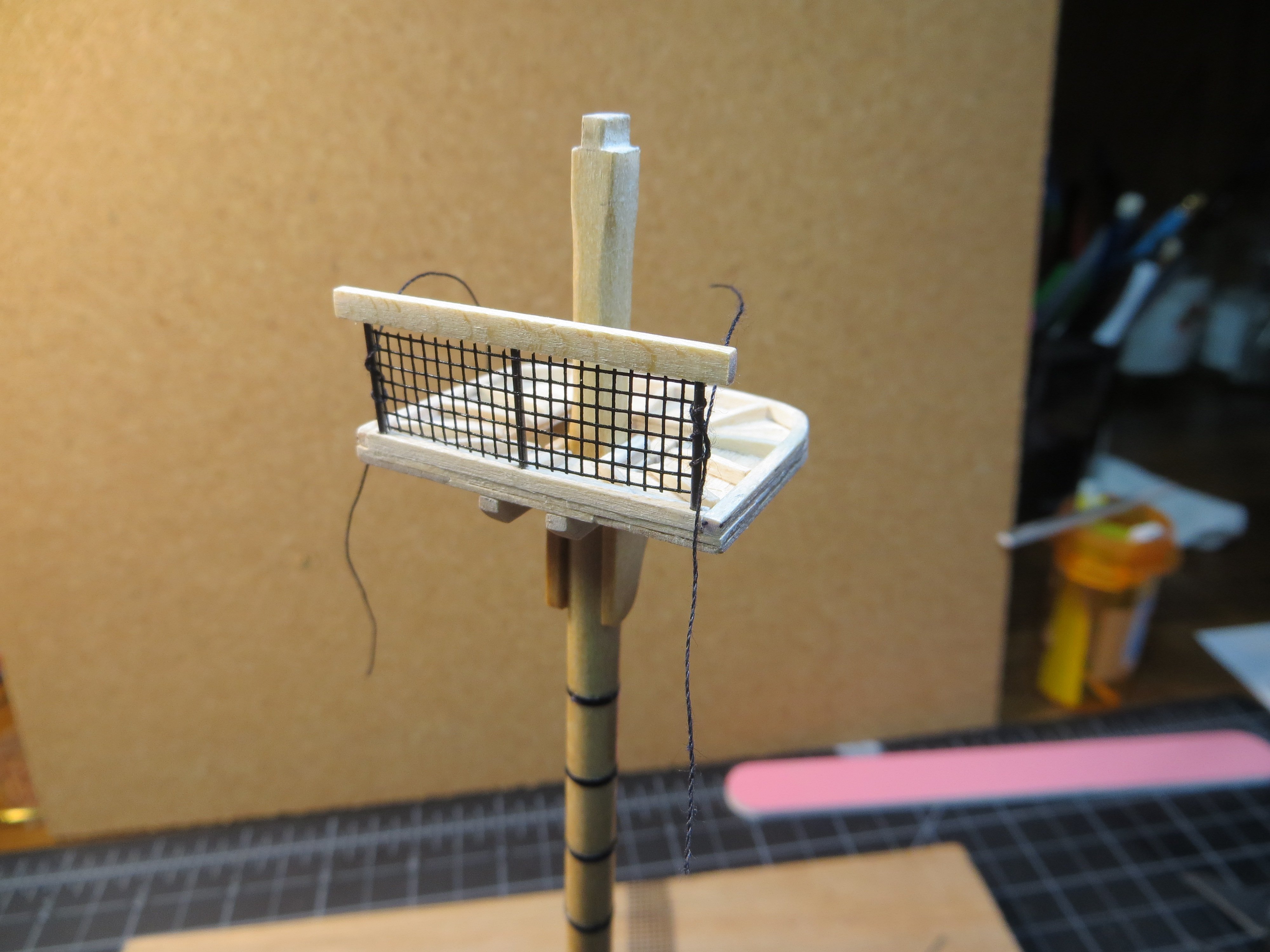
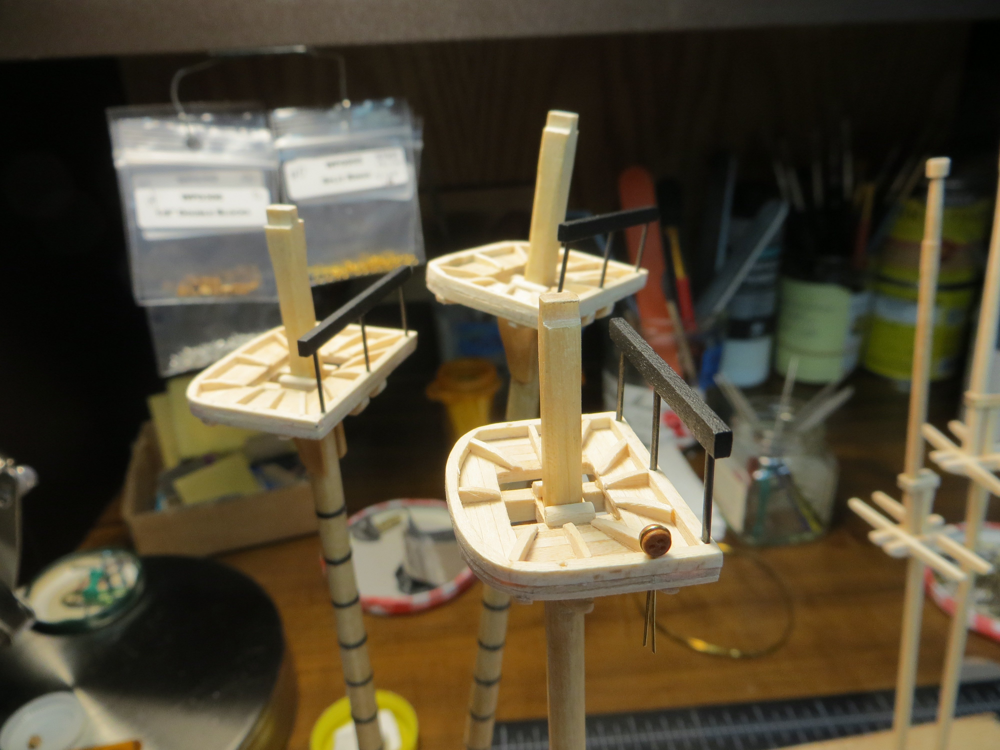
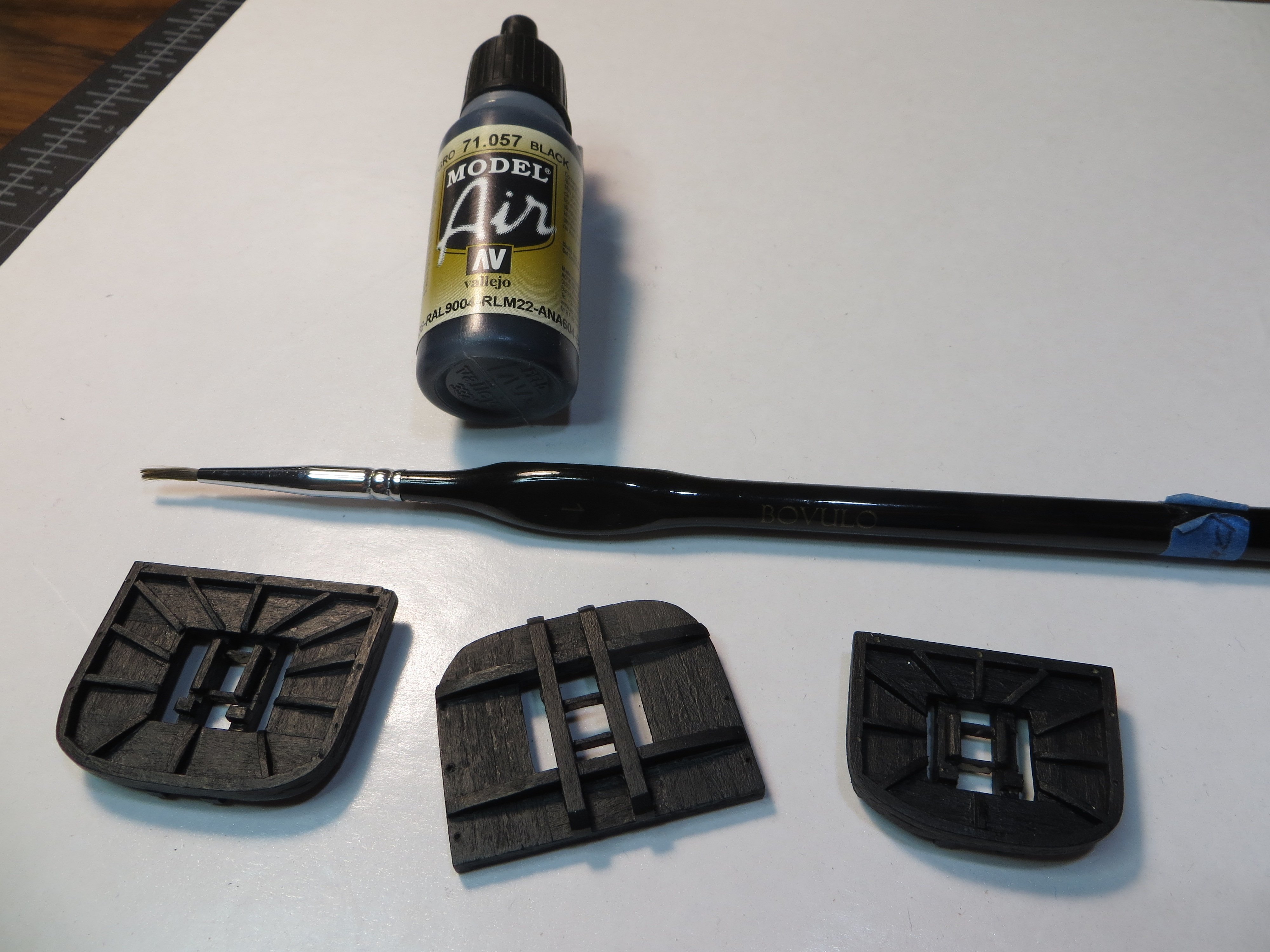
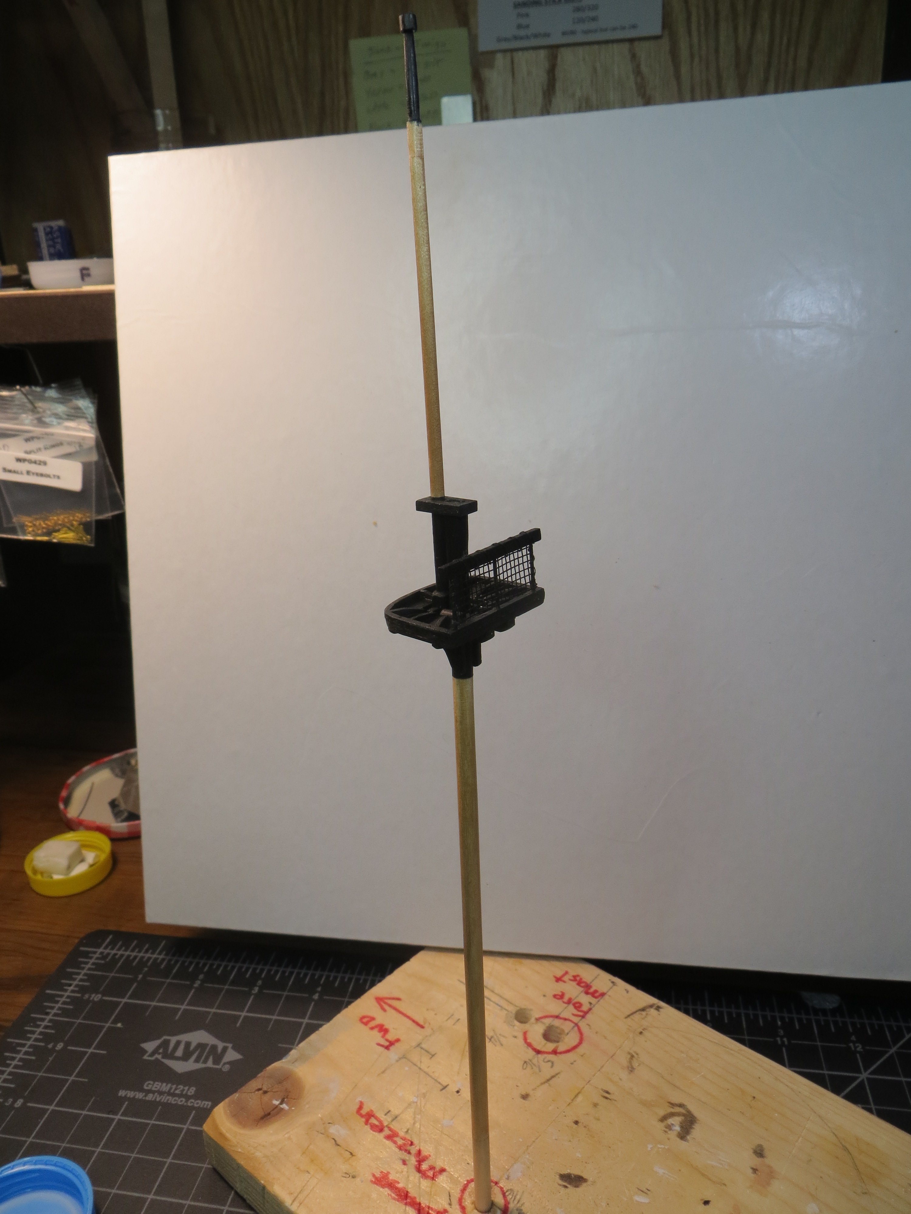
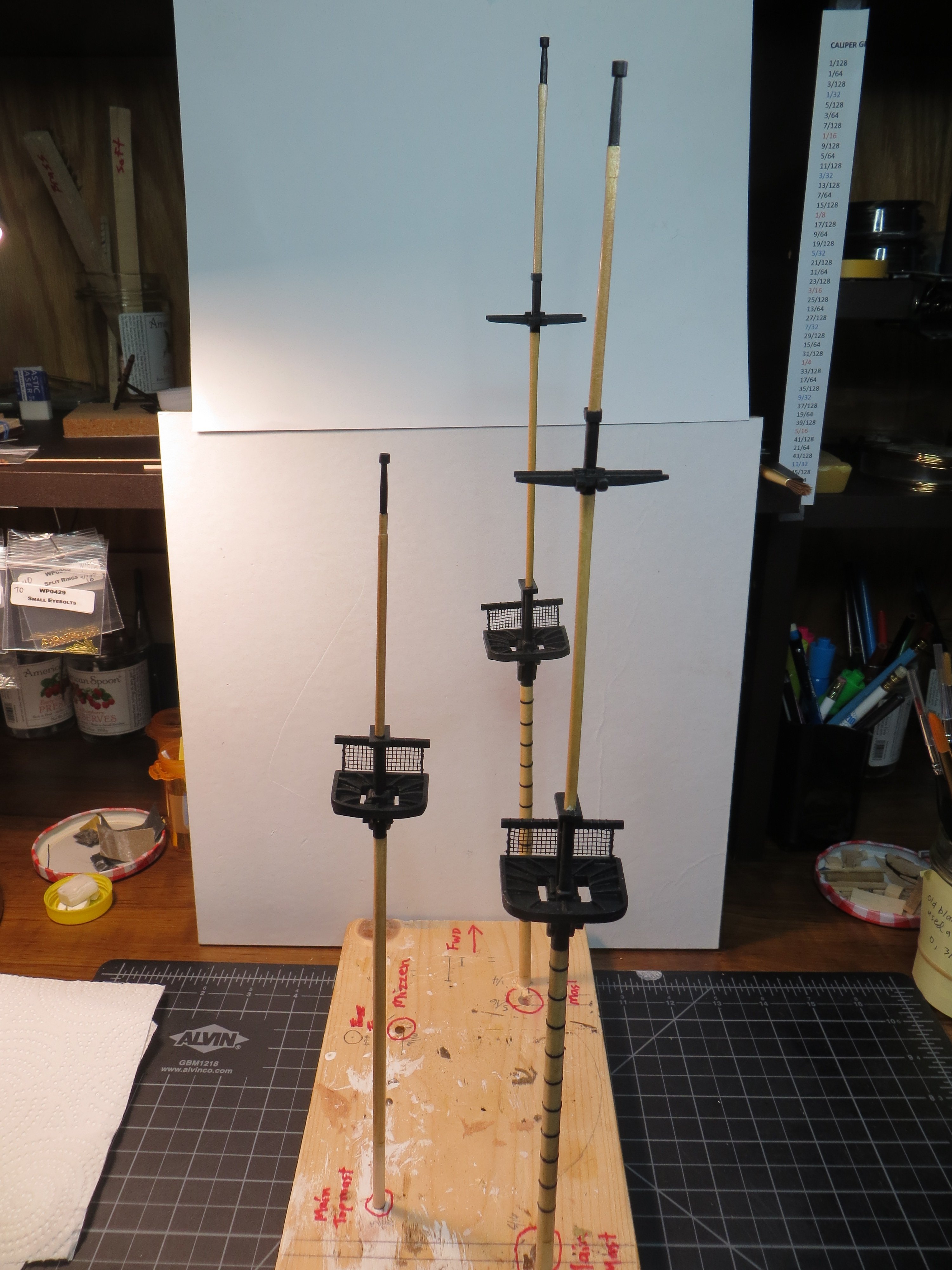
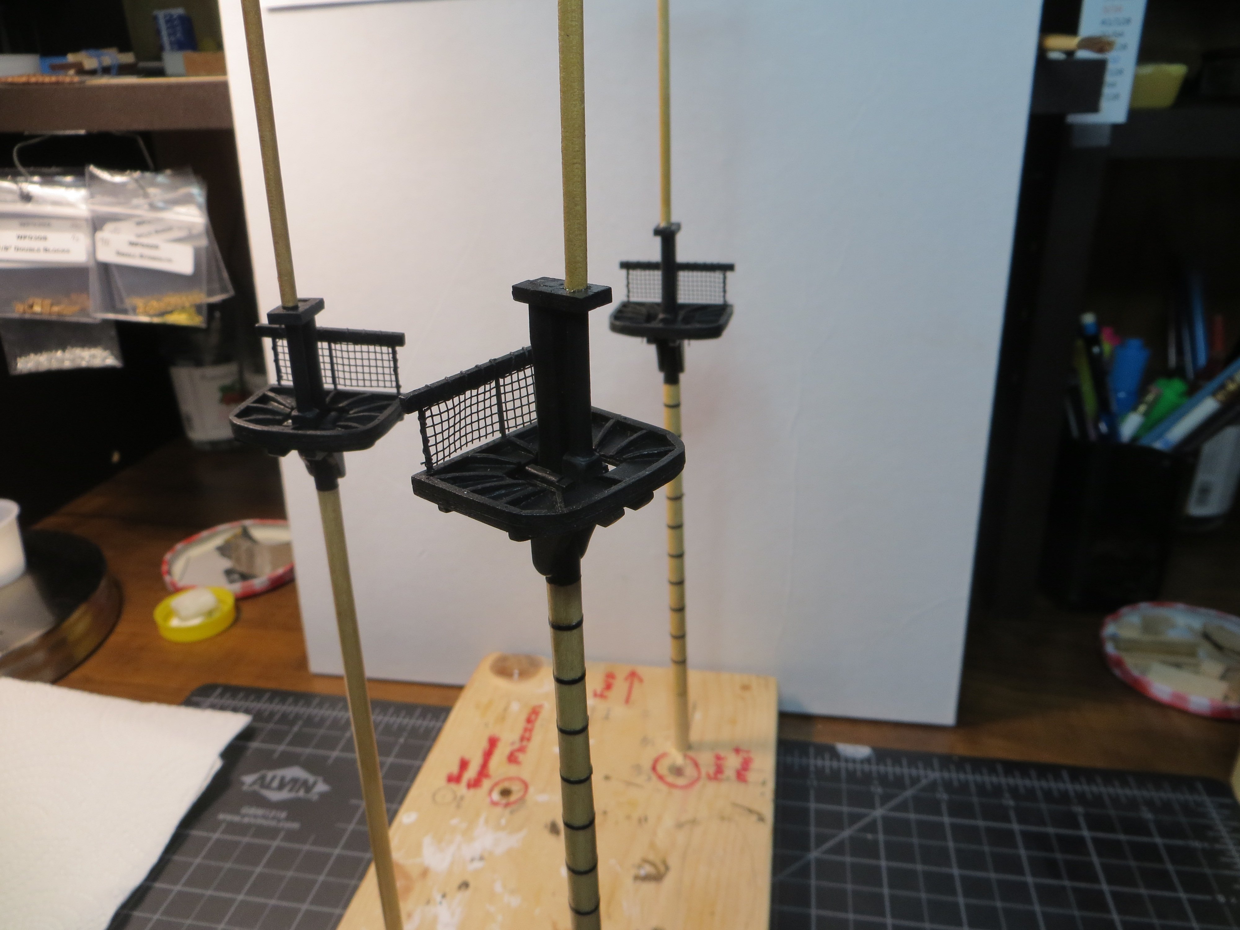
Assembling the 3 Masts, Stanchions & Netting, Staining & Painting Before assembling the 3 masts with glue, I needed to do a few other tasks. Each of the mast tops has a hand rail and some netting on the squared off aft side of the platform. This would be easier to work on while the top is loose. Stanchions & Netting – I’ve seen various methods for making these, including not making them at all! I decided to make mine using 3 pieces of blackened brass rod for the stanchions. I drilled holes in the aft edge of the rim that goes around each top to hold the rods. The rail is 1/16” x 3/32” stripwood. I used some extra screen material I saved for the netting. Some fine black thread is used to tie it to the rail & stanchions. I think it turned out pretty well. Rail and top with holes pre-drilled and 3 blackened brass rods for stanchions. Dry-fit on the Fore Mast Just a loose test fit for the netting The 3 assemblies are completed and the railings painted black. The rods were chemically blackened. At the same time, I decided how I was going to make the deadeyes for the topmast shrouds. I tried a few different ideas and concluded that 0.014” diameter wire had the best scale for the 1/8” deadeyes. I drilled holes to accommodate the twin wires. Here is a pic at this stage in the process. The tops were brush painted with black acrylic Painting & Staining – Next step, I painted the mast areas between the mast caps and just below the cheeks black. The very top of the mast was also painted black down to the top of the shoulder. I was able to slip the mast cap onto the topmast from the bottom for the mizzen mast. Here is the completed mizzen mast. Assembling & Gluing – In my previous post I mentioned the need to split the Fore & Main mast caps in half to get them to fit around the topmast. I managed to accomplish this with only a moderate amount of pain for the main mast by slicing it with the Exacto knife. But the cap for the foremast fell apart in the process! I had to remake this mast cap. This time I made it 1/128” wider and then used my razor saw of the same thickness to cut it in half. As you can see in the pic below, I still lost a chip of wood. But I didn’t want to remake this a third time. I patched the hole up with wood filler and after painting it’s hardly noticeable! I left the areas to be glued unpainted. I used WeldBond glue to get an extra strong bond. It feels quite secure. Here are the 3 masts after painting and gluing. The unpainted wood was stained with Minwax Natural. I still need to apply a coat or two of polyurethane. It’s been so hot the last few days, I’ve been able to enjoy some ship building time in the cool of my basement hobby room! The next thing I plan to work on is the bowsprit. It is like a horizontal mast! Including a mast cap. Ugh!! Thanks for looking in! Ed


-
Fore & Main Mast Caps My next task is to prepare the mast caps for the Fore & Main masts. The mast cap holds the lower mast and the topmast together at the mast top. These caps are provided in the MS kit as laser cut pieces. The round hole for the topmast in the kit mast caps are 3/16” diam. My topmast at the spot where the cap holds it is smaller, at 1/8”. It looks like I’m going to have to make the caps from scratch to get the right size. First, I cut the tenon on the top of the lower masts to fit the mast cap. I cut the Foremast tenon at 3/32” wide and left the full 3/16” for the length. I first cut a shallow line on each side with the Exacto knife 3/32” below the top end of the lower mast. Then I cut an even amount off each side until I had a tenon 3/32” wide. Fore mast after cutting in the tenon The fore & main mast caps are exactly the same. The size for the mast cap should be 1/2" x 1/4" x 3/32" deep per my calculations. In order to get the 3/32” height needed I had to use a wider piece of stripwood. Part # 3628; is 3/32” x 5/16” wide. I marked a line and then used the disc sander to reduce it down to ¼”. I cut the piece off with a little extra length so I had something to hold onto when making the two holes. The hard part is to get the two masts to be parallel between the mast cap and the top. I measured and marked the positions of the 1/8” round hole for the Topmast because I thought it would be easier to drill this hole first. Then I drew a rectangle for the tenon, the required distance from the edge of that hole, to get the masts parallel. I started by drilling 2 holes side-by-side inside the rectangle and then used mini-files to square it off. Finally, I cut the excess off the end. The two mast caps. The fore mast cap is done and the main mast is ready for drilling & shaping The mast cap dry fit on top of the Lower Fore Mast section. (In case you're wondering...that’s the mizzen mast on the build board behind it) Please Note: This is not mentioned in the MS instructions, but is in the practicum. I will need to cut the mast caps in half, the long way, to get them on the topmast. Cutting them with any kind of saw would remove wood with the kerf and change their dimensions! I did a test run on a scrap piece with a chisel that did not work! The cut was uneven & ugly. So, I tried using the Exacto knife by slowly deepening the cut. This seems to work. I will try this when its time to assemble everything. Nothing has been glued yet. Mizzen Topmast Since the Mizzen does not have a Topgallant mast, I decided to make the Topmast for the Mizzen next. Then I will make the Topgallant masts together. The mizzen sizes are different from the fore & main topmasts. But otherwise, the technique is the same, except for the ball at the top. The ball will be on the Topgallant masts for the two larger Fore & Main masts. Here are my steps for making the Mizzen Topmast: a. Use a 1/8” dowel that is 4-9/16” long. I cut it an extra 1/2” long for insertion into the drill chuck for sanding into shape. b. Measure 1/32” down and make a mark for the ball at the top. Measure 5/8” down from the top and make another mark, which is the top of the shoulder. Tape off the heel area and at the bottom of the shoulder area. Then taper the section in between from 1/8” to 3/32” in diameter where it meets the square section. From the top of the shoulder, it goes from 3/32” to 1/16" at the top just under the ball. c. Make a square shape at the shoulder a ¼” long. The practicum says to make this square into an octagon, but the MS does not show this. I left it square. This picture shows the tenon cut into the lower mizzen mast, the built-up bottom of the topmast before final sanding and the mast cap that is still under construction. d. The practicum says to shape the top 1/32” into a ball. Although their picture looks more like a round disk. My first attempt to do this resulted in breaking the ball off while thinning the mast below it down to 1/16”! So, I decided to use the same method as I did on the Bluenose. Make a round disk separately and glue it onto the top of the 1/16” point at the top of the mast. This also has the advantage of allowing the mast cap to be slipped onto the mast from the top without having to cut it in half. I started with a 1/8” dowel. A small hole was drilled in the end of the dowel and expanded gradually to 1/16”. I cut off a 3/32” length, with the hole being about half that depth. I thinned the top of the mast until the hole fit snuggly on top. I could have made it into more of a ball shape, but I actually like the way the disk looks. Here is a close-up of the round disk dry fitted onto the topmast. (sorry about the focus) This won’t be glued on until after the mast cap is glued in place e. There is a 3/16” long square section at the heel that needs to fit into the Trestle Trees of the lower mizzen mast. I glued 1/32” thick pieces of stripwood to build up the mast heel. Two sides are 1/32 x 3/32” stock and the other 2 are 1/32 x 1/8” stock. This was to allow for the overlap. This was sanded to fit into the hole formed by the chock and trestletrees Here are the finished pieces for the Mizzen mast. Mizzen Mast Cap – I used something closer to the MS plan measurements. The practicum dimension was way off on the width at 1/16 W x ½ L x 3/32” D. The exact dimensions after final disc sanding: 29/64 L x 17/64 W x 3/32”. Otherwise, the steps were the same as with the Fore & Main. Mizzen Mast Cap dry-fit on the topmast The completed Mizzen Mast dry-fit together Fore & Main Topgallant Masts These two masts are made using 1/8” dowels. The Fore Topgallant is 3-5/8” long and the Main is 3-3/4”. I added an extra ½” to each for insertion into the drill chuck for tapering as with the other masts. Otherwise, it is shaped very similar to the Mizzen Topmast. After the Topgallant masts were sanded to shape, I made the Trestletree & Crosstree assemblies. I learned from making the lower top mast TT’s/CT’s that it is important to be precise on the cuts where the 4 pieces intersect. I had to remake a couple of pieces because they were not square and flat. You can hide imperfections a little easier on the lower mast because it is glued under the mast top. But, I wanted these to be as precise as I could make them because they are exposed right there at the top of the model! I achieved this by cutting all the pieces at the same time. Taping them together with masking tape. Sanding the ends on the disk sander to make them the exact same length. Using a 1/32” thick strip in the chock slot and tape to hold the TT’s together while cutting the grooves. Labelling the parts so they stayed in the position they were made for. Those are just a few of the steps I used to make them as precisely as I could! Still not perfect, but I think they will pass inspection! Here is a pic showing what I described above. I also made the bottom tab on the chock the exact width needed to fit the width of the topmast tenon and the topgallant heel Dry-fit of the assembly Main Topmast, Topgallant & Trestletree pieces are completed The last thing I completed in this step was the two mast caps. I was able to use the kit supplied laser cut mast caps. I even discovered that I could slip these on over the heel of the topgallant. Here are the finished Fore & Main Topmast & Topgallant Masts (still only dry-fit!) I have not glued anything yet. I have to drill holes in the tops for the deadeyes and the stanchions that hold the netting and numerous eyebolts. I will do these now before gluing. I also intend to paint and stain everything. It seems like it’s taken forever to get these masts built. According to my log I started the lower masts on Feb. 19th. Almost 3 months ago! Patience is a virtue! Happy Memorial Day! Ed


-
LOL!! THAT'LL BE THE DAY!!
-
Gregory, Here is how the practicum shows the crosstrees/trestletrees. This is a picture of the Fore Mast showing the connection at the top of the Top Mast and the heel of the Topgallant mast. Both are inside of the crosstrees with the chock in between. The more I think about it this arrangement seems pretty straightforward. I never noticed that some ships had 3 crosstrees at the topgallant! I’m kinda leaning toward doing it like the practicum. Mainly because it is a simpler design. But I’m still thinking about it. I really appreciate your feedback and the references to the historical data. Thanks, Ed
-
I have a question for Team Rattlesnake. I'm working on the Trestletrees for the topgallant masts. The MS plans show the topgallant mast heel positioned in front of the forward trestletree and a chock in front of the TG mast heel. The practicum says to center the chock in the hole and fit both masts inside of the TT's with the single chock in the between them. It seems odd to me to put the topgallant outside of the TT!! What do you think is the correct way?
-
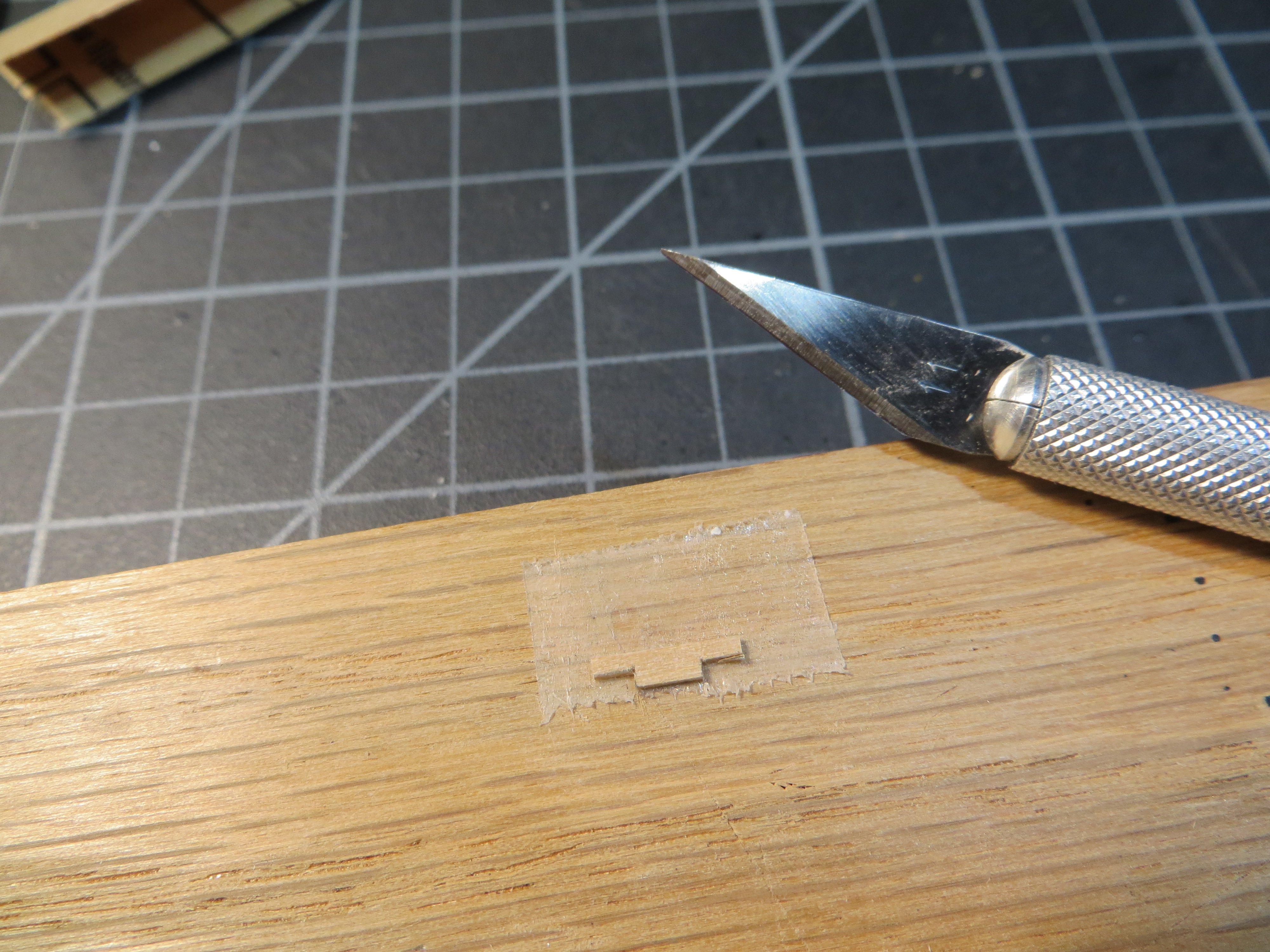
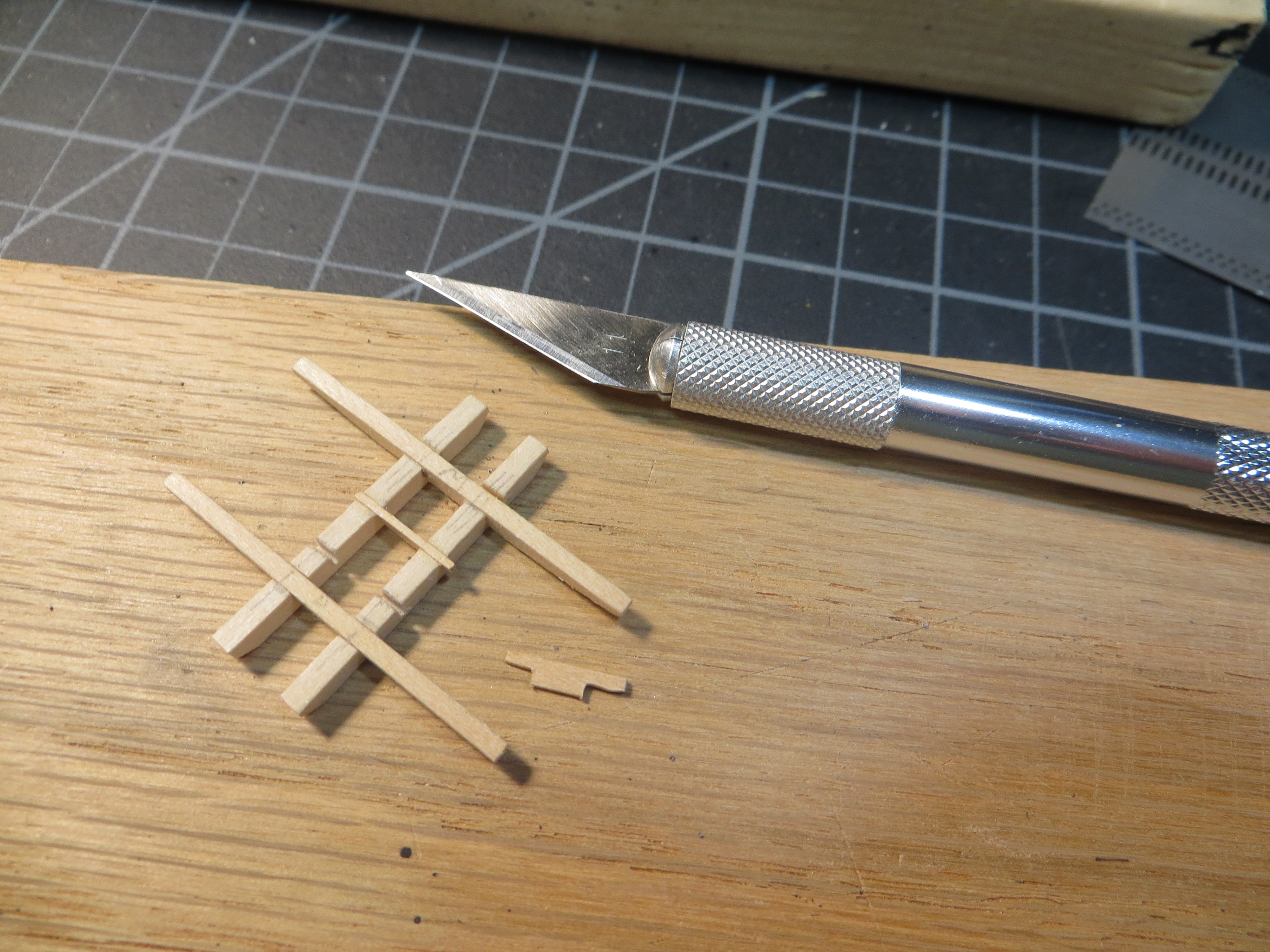
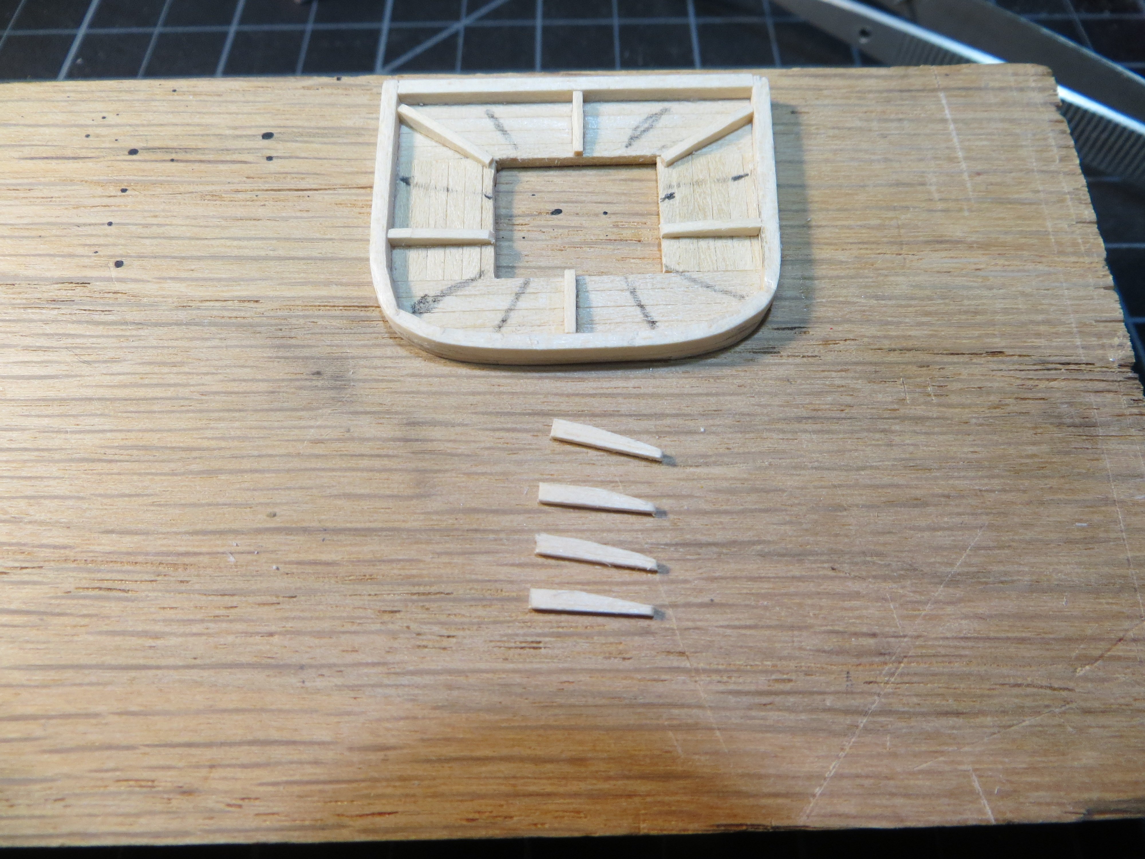
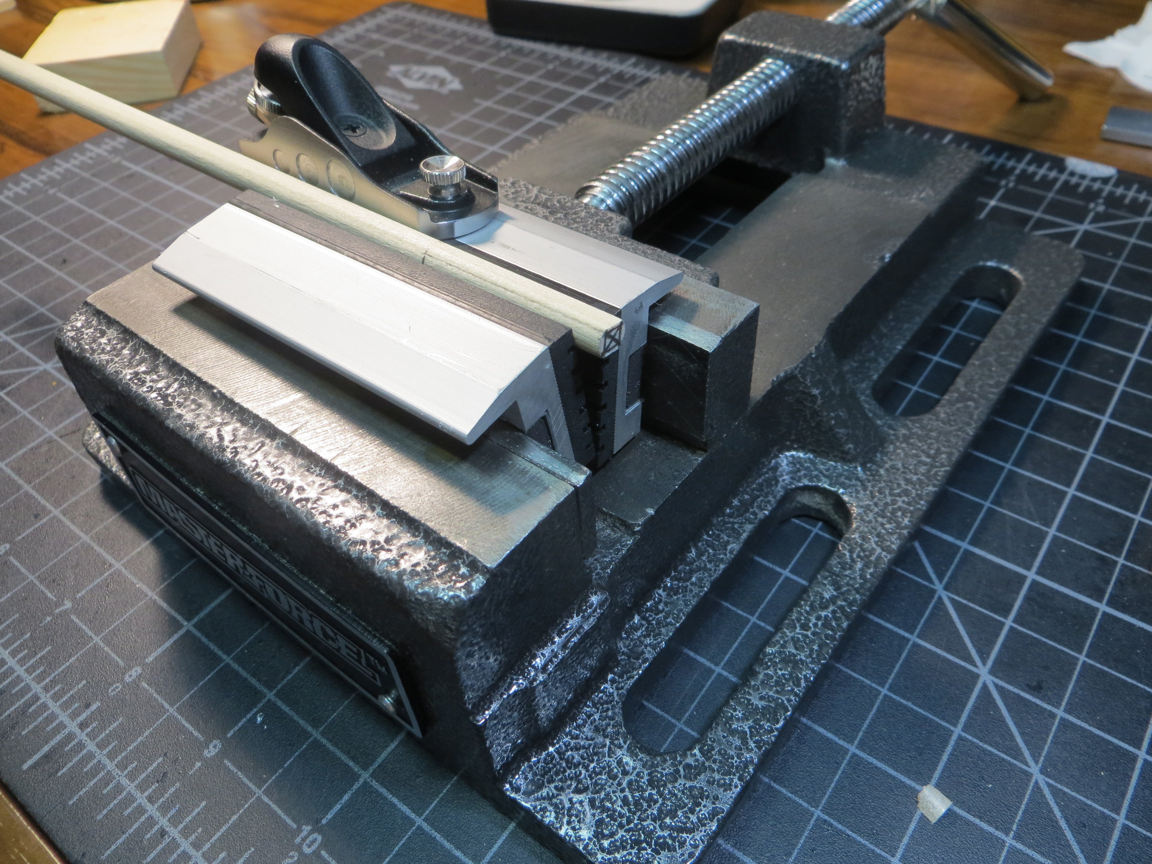
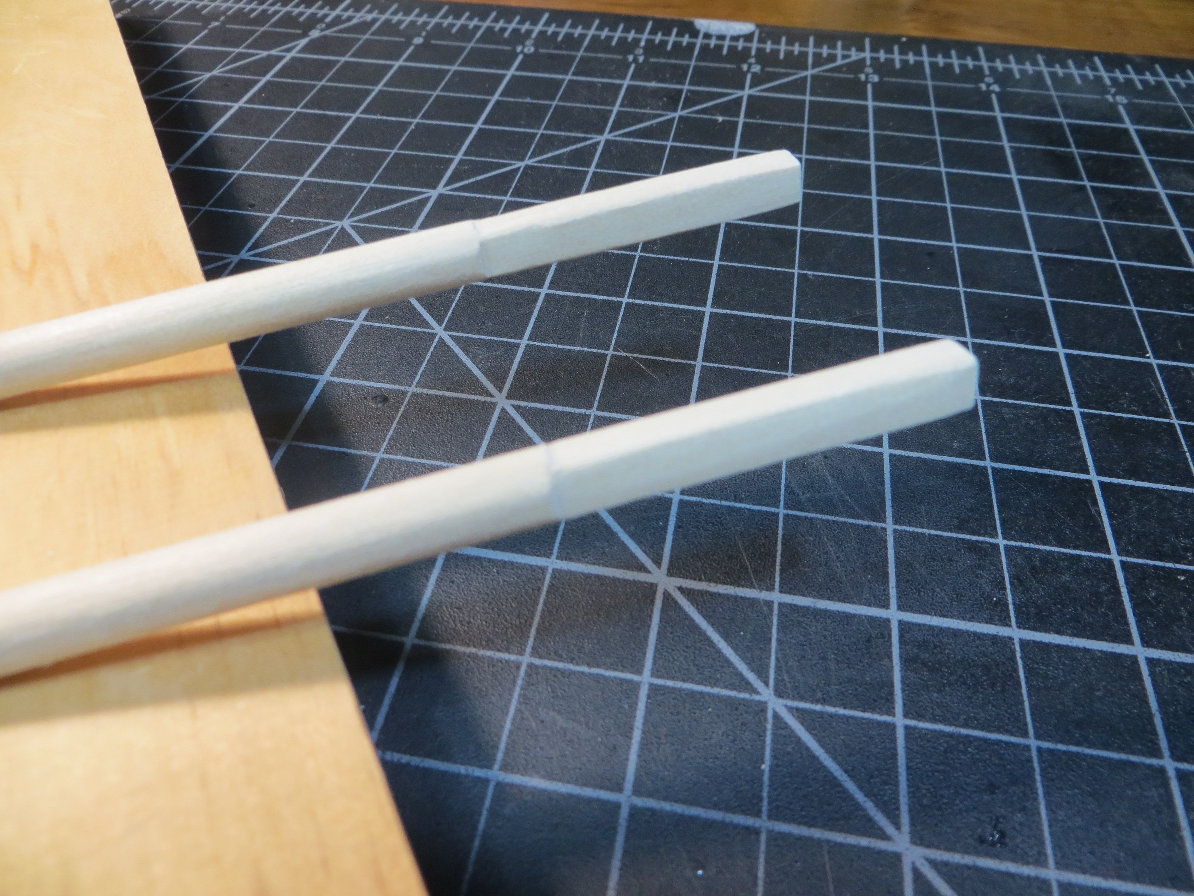
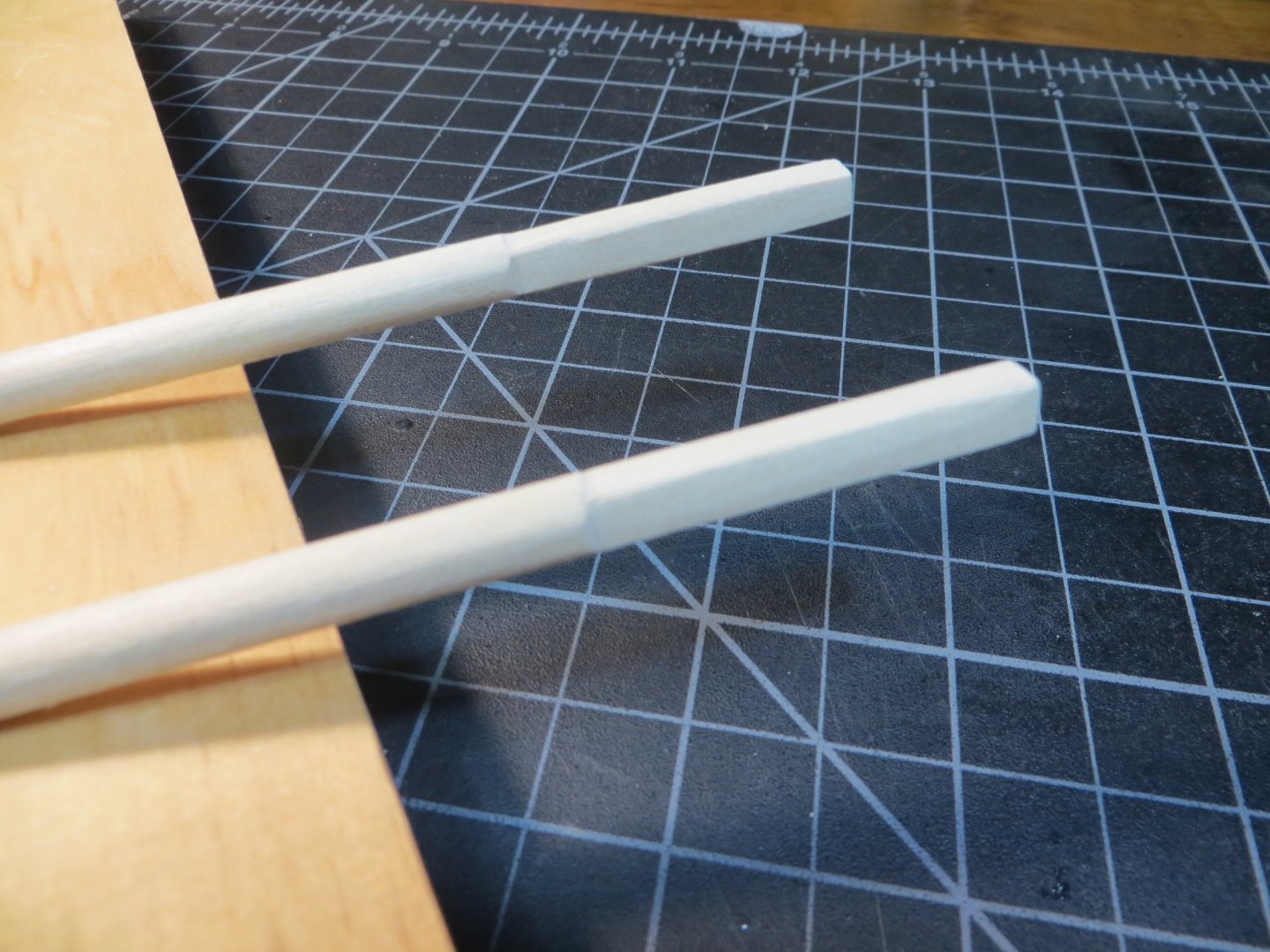
The Crosstrees & Trestletrees The Crosstrees (CT’s) and Trestletrees (TT’s) hold the Tops to the masts. These pieces must fit the rectangular opening of the top and also are centered and fit the square top section of the lower masts! The trestletrees are heavier and run fore and aft, sitting on top of the mast cheeks. The crosstrees are a bit smaller and run side to side. Making the notches and getting it all square is the hard part! 1. The practicum says to cut all the pieces from 3/32” x 1/16” stripwood. Jon Gerson, whose build log I’ve been following, says this is not correct. The trestletrees should be made from 3/32” x 1/8” stock. And the crosstrees are 3/32” x 1/16”. 2. The practicum says to make the TT’s 1-1/8” long and the CT’s 1-1/2” long. But in reality, the TT’s are as long as your tops and the CT’s are as wide. Since they are essentially custom made, I did them one at a time. I started with the fore mast and cut out the 4 pieces according to my measurements. 3. I started with the TT’s. Notches are to be made so that the inside edges of the notch match the inside edges of the opening fore & aft in the mast top. The notches are 1/16” wide and 1/32” deep. Make an angle on the end that is 1/16” in from each end. 4. The Crosstrees also need to be notched so they match up with the notches in the TT”s. They are closer together. They need to encase the mast and hold everything together. They have a different cut on the bottom. Measure 3/8” in from the end and make a mark. Shave an angle from that mark outwards so that the crosstree is 1/32” thick at the end. Foremast Trestletrees & Crosstrees dry-fitted and 4 pieces of stripwood cut out for the main mast Test fit the assembly on the foremast At this point I’m supposed to make the Chocks. Two per each assembly. They sit in a notch between the trestletrees just like the crosstrees are fitted. One goes between the square section of the mast and the aft part of the rectangular opening. The other one goes in front of the lower mast but behind the hole for the topmast. I realized that I needed to make the Topmast now so I could use the heel to measure where to place the first chock. So, I’m going to show making the Topmasts next. I will continue with steps for the Chocks & Bolsters afterward. The Fore & Main Topmasts 1. The practicum says to use 3/16” dowels for the Topmasts. The MS parts list says to use a 5/32” dowel for the Fore & Main Topmasts. Since the 9” piece of 3/16” supplied in the kit was already used for the Mizzen mast, I went with the 5/32” dowel. The Fore Topmast is 5-3/4” long. The Main Topmast is 6-1/4” long. The Mizzen Topmast is 1/8” x 4-9/16” long. I cut them an extra 1 inch for a new technique (at least for me) that I wanted to try. 2. The top is square, like the lower masts. Mark the top of the dowel with a square to create a 3/32” square. Measure down 11/16” and make a mark. I locked the dowel in the vise and used the mini block plane and a sanding block to make the square top. Dowel secured in the vise and the indispensable mini plane 3/32” squared off section at the top of the Topmast 3. From the bottom of the square to the 9/32” long X 3/32” square mast heel the topmast needs to be tapered to 1/8” round. I had a difficult time hand sanding the tapers on the lower masts. This time I decided to try using a method I’ve read about in other build logs. I taped off the top and bottom of the dowel that needs to be square. Inserted end with the extra 1” into my power drill. I squeezed sandpaper around the dowel and ran the paper up and down with the drill spinning the wood. This worked very well for me. I kept checking the diameter until I had an even 1/8” topmast! Here is the dowel in the drill A little hard to see, but here is the mast after tapering 4. I used another new technique to hold the square top end of the mast in the vise with some flat blocks of wood on the squared off sides. I sanded the heel end down to a 3/32” square. This is the best way I could think of to make sure the squares on both ends of the mast were lined up. This worked well for me too! View of the set-up in the vise. A 3/32” square laid on the bottom keeps the sides parallel when the mast is held above. Pic #2 with the mast locked in place Pic with first two sides flattened with the sanding block in the background 5. The bottom heel of the mast needs to fit into the mast top, between the TT’s, forward of the lower mast. The sides have to be built up to fit this space. I glued pieces of 1/32” stripwood to the bottom square. It was sanded down to smooth off the edges. 6. At the top end, the square needed to be sanded into an octagon shape. I used the MS plans for this area. The space between the topmast and lower mast up to the mast cap needs to be parallel. Now that I have the topmast, I was able to take a measurement for the chock behind the heel. The heels of the topmasts are fit tightly into the trestletrees. Chocks – are taken from 1/32” x 3/32” stripwood and cut in the shape of a “T” with a fat stem using an Exacto knife. There are two per top. Cut a notch for this chock in the trestletrees using the topmast heel as a guide. Keep a snug fit for the bottom of the topmast. Another Chock is glued into notches for the lower mast. All four sides of the mast are locked against the trestle trees and these cross pieces. The TT assemblies can now be glued to their tops Dry fit for the fore & main masts and tops Bolsters – are made from 1/16” square stripwood. The outside top edge of the bolster is sanded with a quarter circle to allow lines to drape over them without damaging them. They sit on top of the trestletrees and tight against the lower mast. I still have some work to do. Like, pre-drill holes for eyebolts, deadeyes and the stanchions for the netting on the tops. Also, the mast caps, which seem like they will be a little tricky to install. Then I plan to paint from the Cheeks to the Mast Caps black. I will complete this same area on the Mizzen mast with the Topgallant masts. The topgallant is the only upper mast for the mizzen. Happy Easter! Ed


-
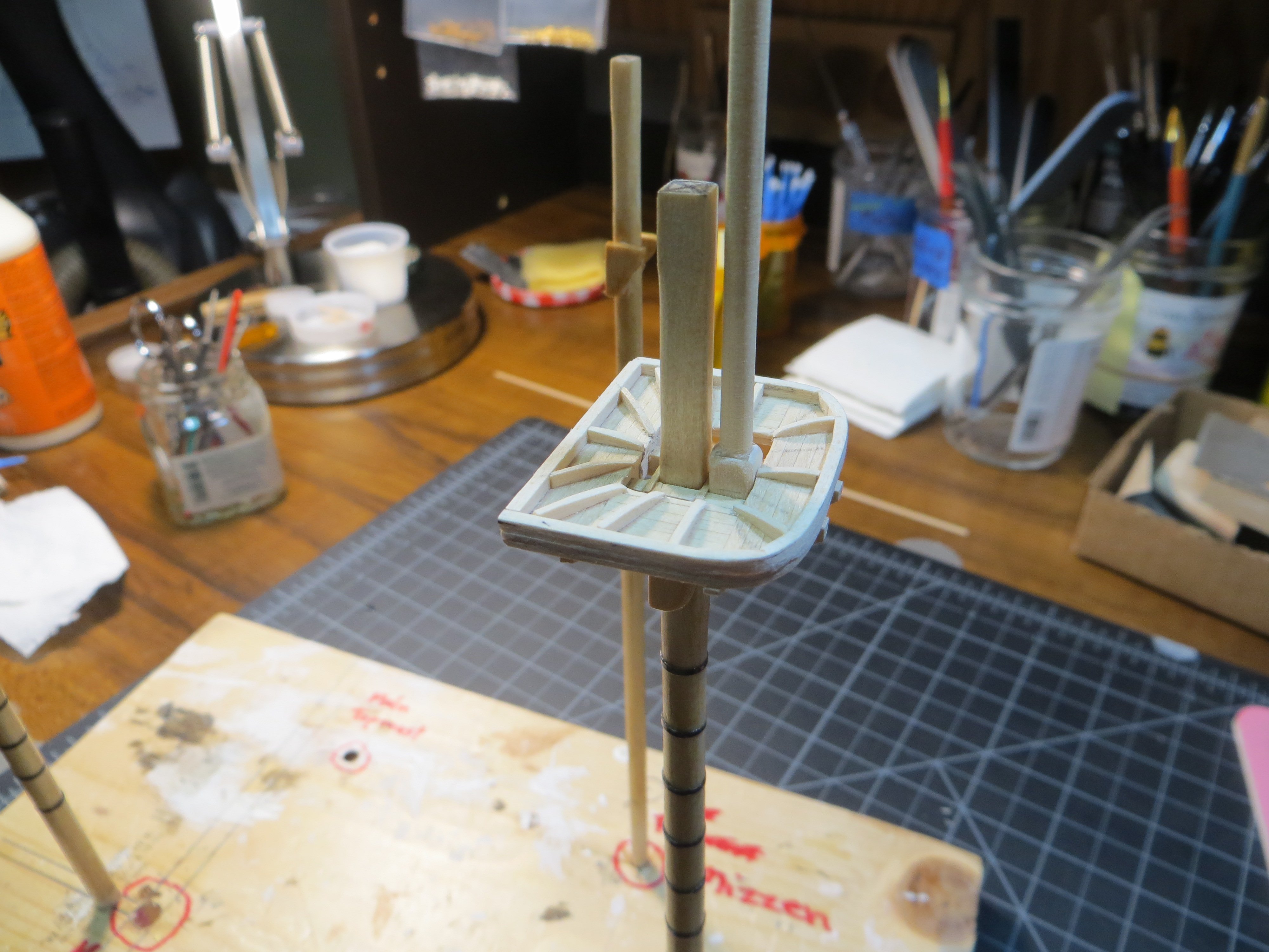
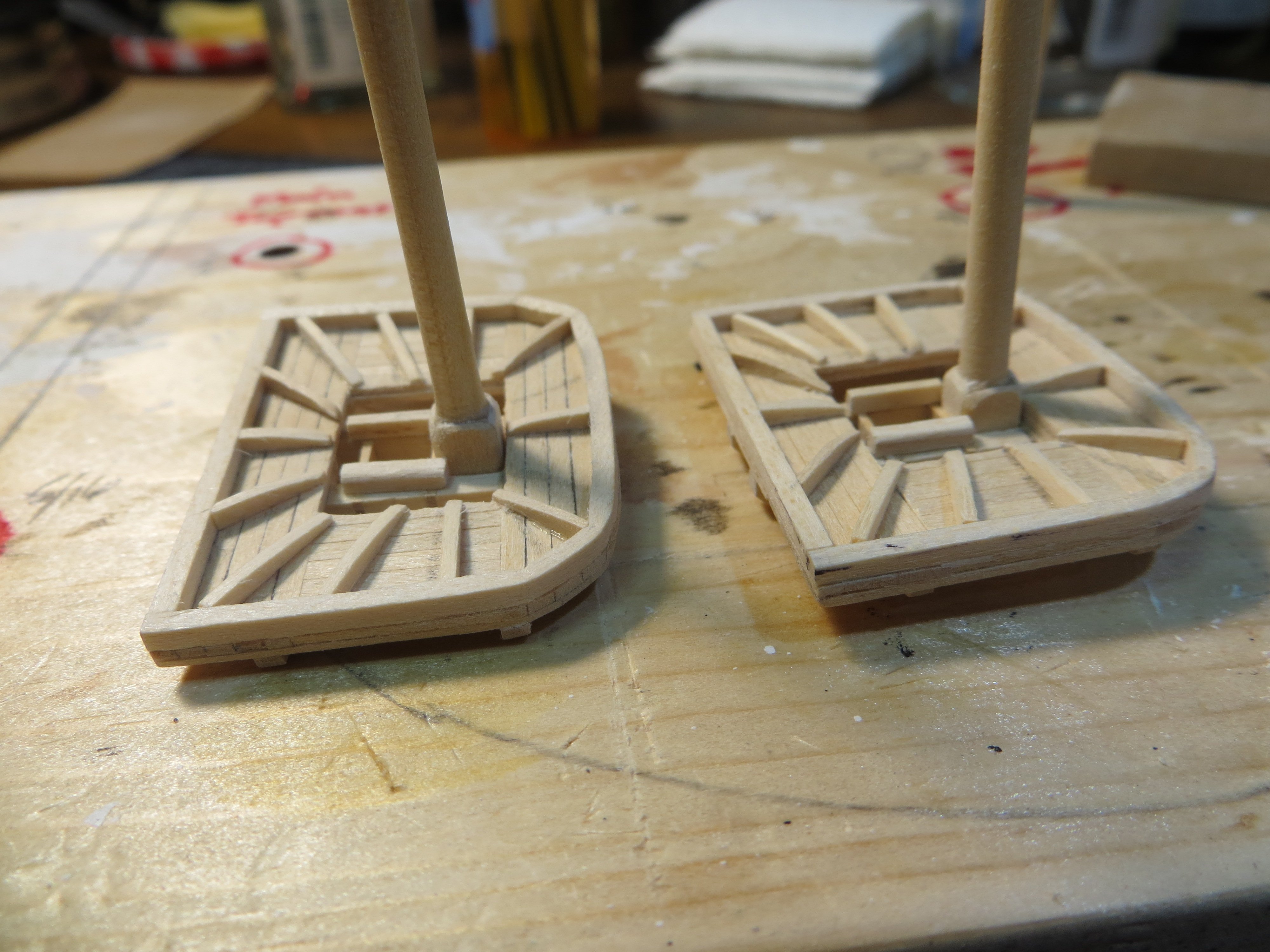
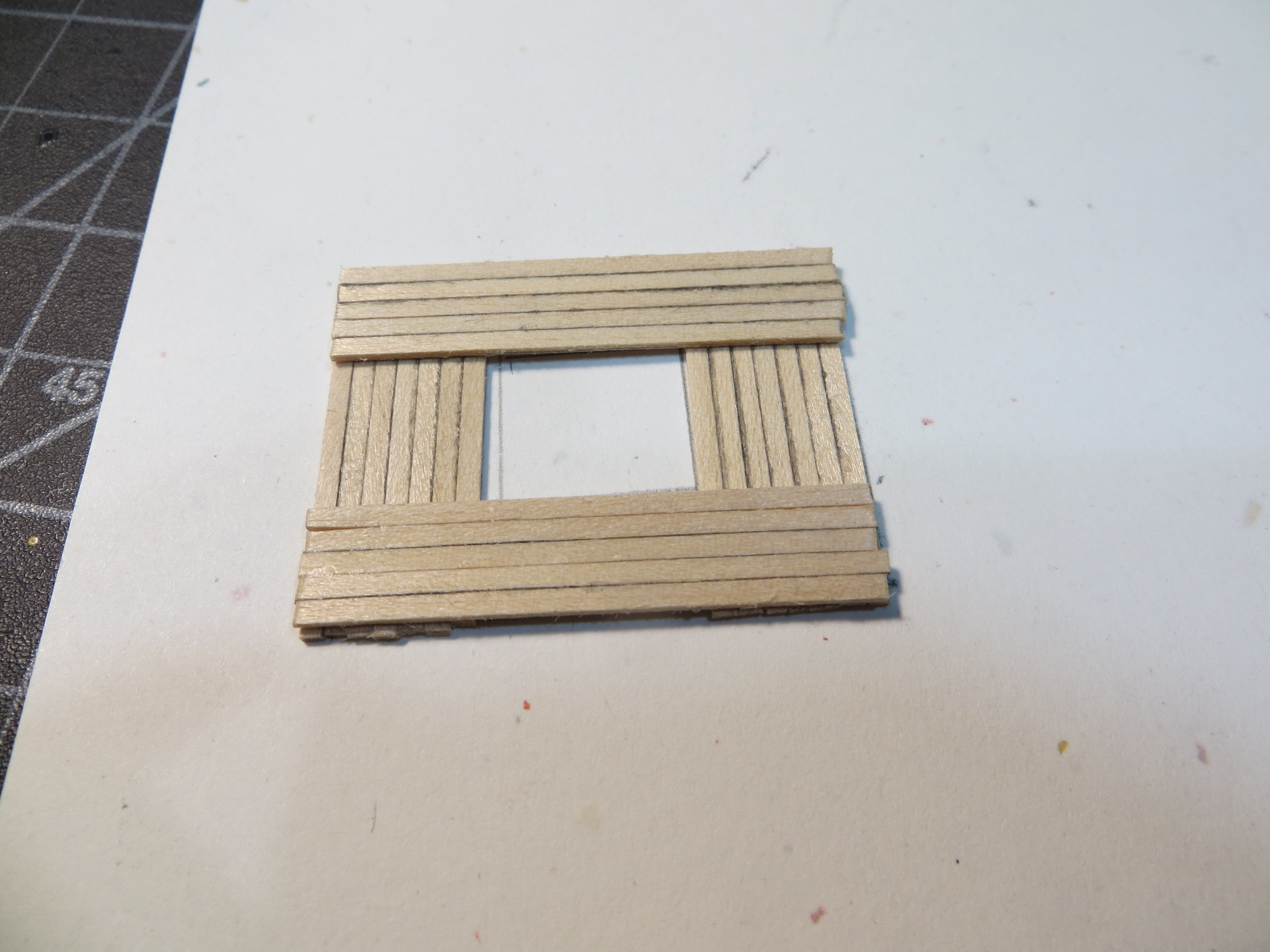
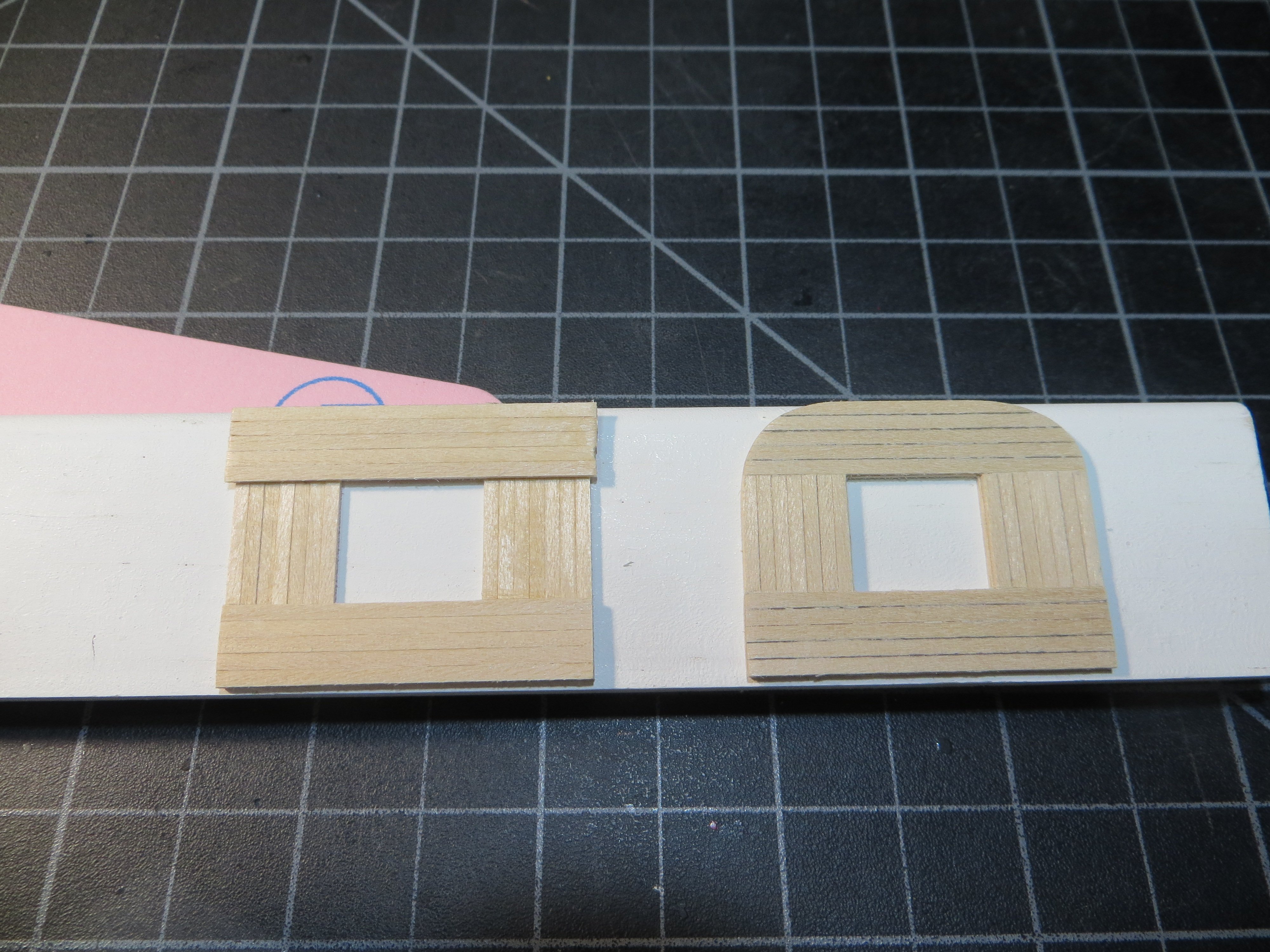
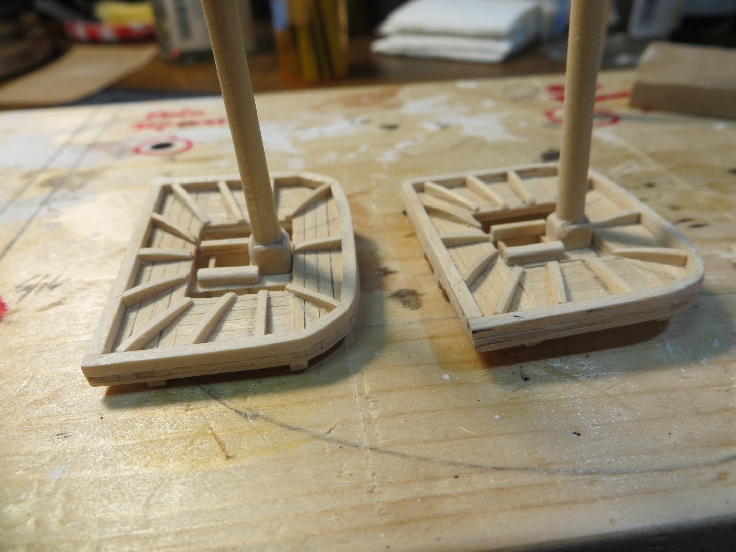
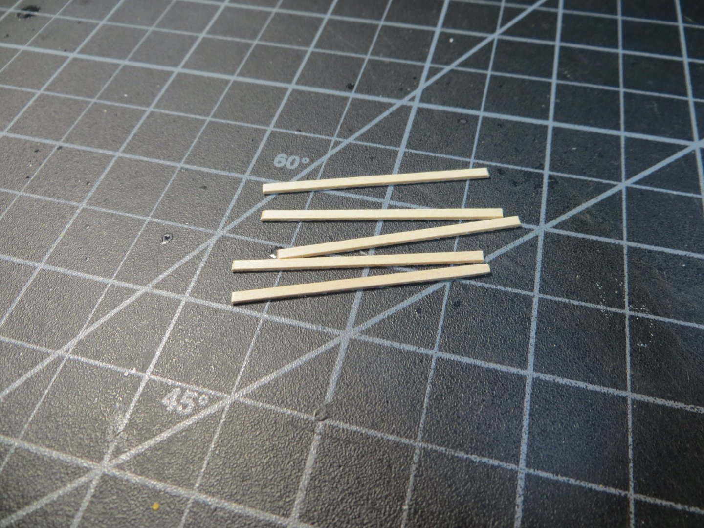
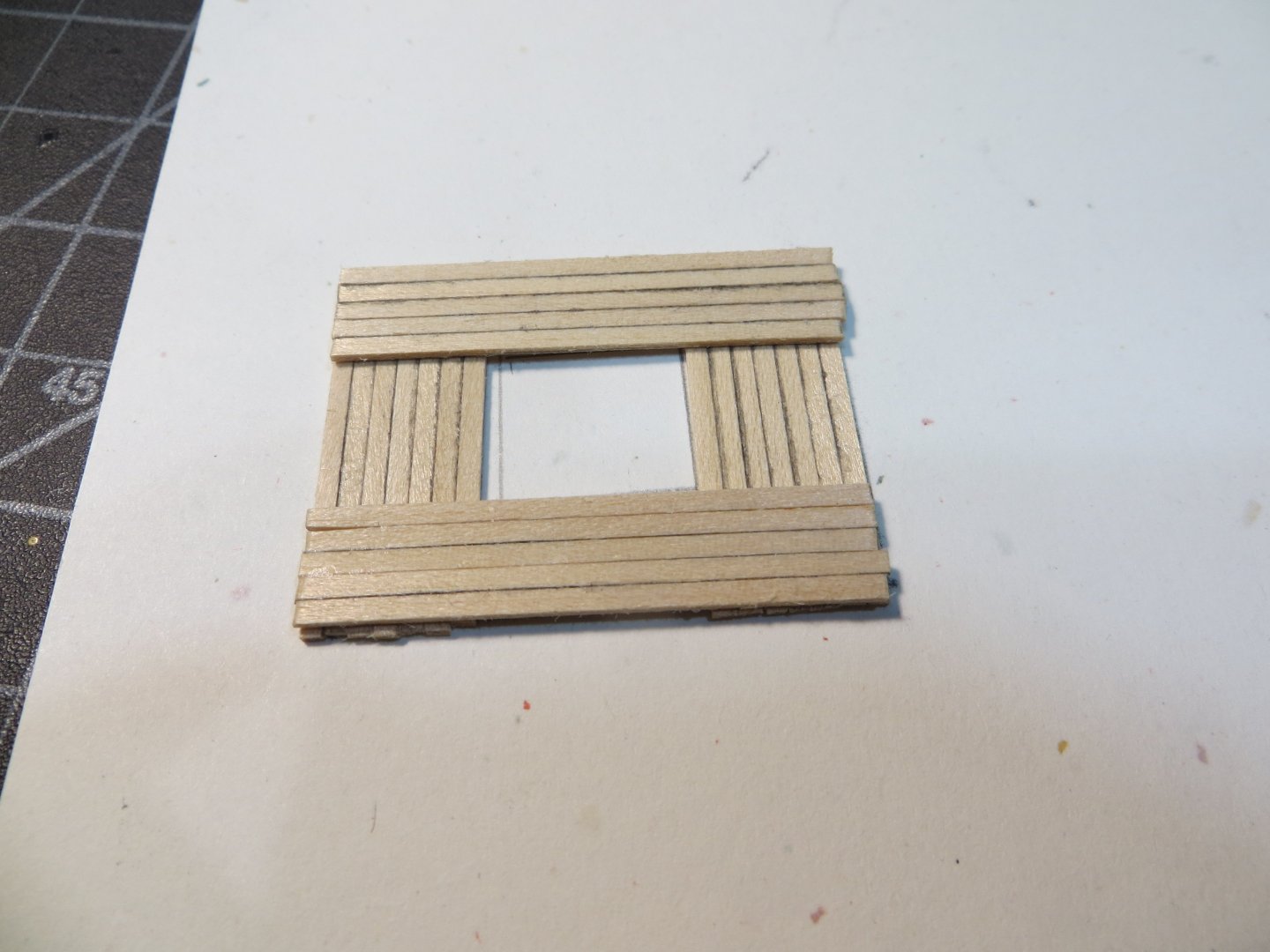
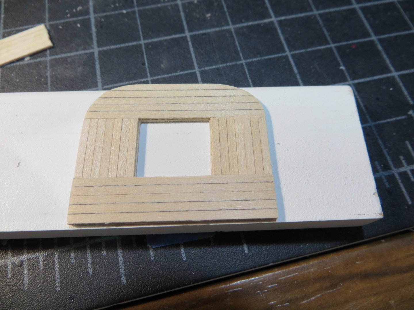
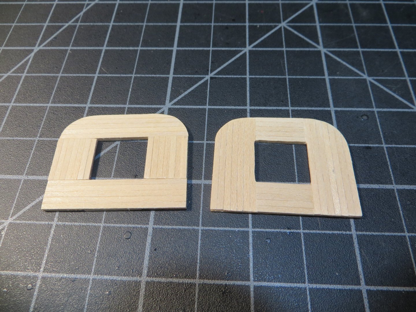
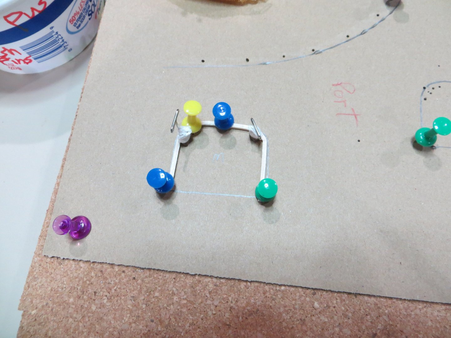
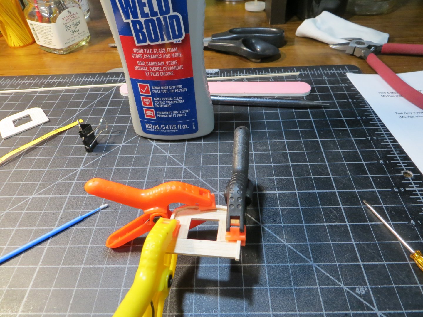
Making the Mast Tops The mast tops sit on top of the Cheeks that were glued to the top of the lower masts in my last post. Both the MS plans and Hunt’s practicum call for using 1/16” square strips for the tops. Then you are supposed to remove 1/32” of the thickness from the ends on each of the four sides before lap-gluing them together. I do not own the mini-table saw that is needed to make such a precise dado cut. So, I had to come up with a different plan. The tops for the Fore and Main Mast are exactly the same size. So, I built them at the same time. The Mizzen is slightly smaller. I built it when I was done with the first two. Eventually they will be painted black. a. I’m using all 1/16” width x 1/32” thick stripwood. I had to request more of this size stripwood from Model Expo. After lots of careful measuring and making drawings of the tops, I cut stripwood to length. b. The strips were edge glued together. I used one of my jigs to keep the sections flat and square. The sections were overlapped together to form a square around the center hole. The overlaps provided the required 1/16” thickness. The middle sections that were not overlapped were still 1/32”. c. Then I fitted some more 1/32” pieces to fill the gaps in the 4 middle sections (top & bottom). I used the disc sander to shape the rounded off forward edge and even off the straight sides. On the right is the finished top for the Fore Mast. On the left is the Main top in process. Pic #2 below: both of these tops completed. d. The platform has a 1/16” square edge around, but ON TOP of the completed mast top. It’s a bear to bend the curve around that forward edge! I soaked the square piece of stripwood for 30 minutes and used a curling iron to start the bend. Then I pinned it down on a corkboard using an outline of the top as a guide. I let the wood dry to shape for several hours. I broke one of them, but eventually was able to make 3 decent edge strips. e. Weld Bond was used to glue the edge onto the platform. I clamped it until dry. The outer edge was sanded smooth. f. The fore mast top with the edge around 3 sides. The aft edge was easy to fit and glue a straight strip on. Here is the Mizzen Top under construction g. The next step was to add ribs on the upper side of the tops, that radiate out from the center hole. These are made from 1/16” x 1/32” stripwood. They start out flush with the top of the 1/16” edge and then taper down in height towards the center hole. Each one has to be individually measured and sanded to shape. I made a template from the plans. But it seemed too crowded, so I cut down on the number of ribs. Fore & Main Tops marked up from the template using carbon paper 4776 I worked on them in pairs, adjusting their position to get even spacing The 3 finished mast tops I’m circling back to my previous post. Here is a picture of the lower masts, dry fitted after adding the mast rings and applying 2 coats of poly to seal the rings. Next up, I plan to drill all the holes for any rigging that is attached to the tops now. In addition to adding trestletrees, crosstrees, aft rail stanchions with their netting, futtock shrouds, plates for deadeyes, etc. There’s a lot going on with these mast tops! Stay tuned! Ed


-
I have the Amiti Keel Klamp. I used it for my Bluenose build. But, I snapped off a couple of the bulkheads during hull planking while using it on the Rattlesnake. I never went back to it after that terrible experience! I've decided to mount mine on the board that I'm making real soon. I'm thinking it will bring the ship closer to the workbench surface. The keel vice really raises the ship up high. Although I agree, the ability to tilt it helps at times. I can always take it off the mounting posts if it doesn't work out. That's a really beautiful looking ship Darivs!! It looks like you are just about finished. Thanks for your advise! Ed
-
Well, no one has shared any horror stories about putting their model into it's permanent stand for the rigging process. So, I am making the stand for my Rattlesnake now. I appreciate everyone's positive feedback on my progress! Thanks, Ed
-
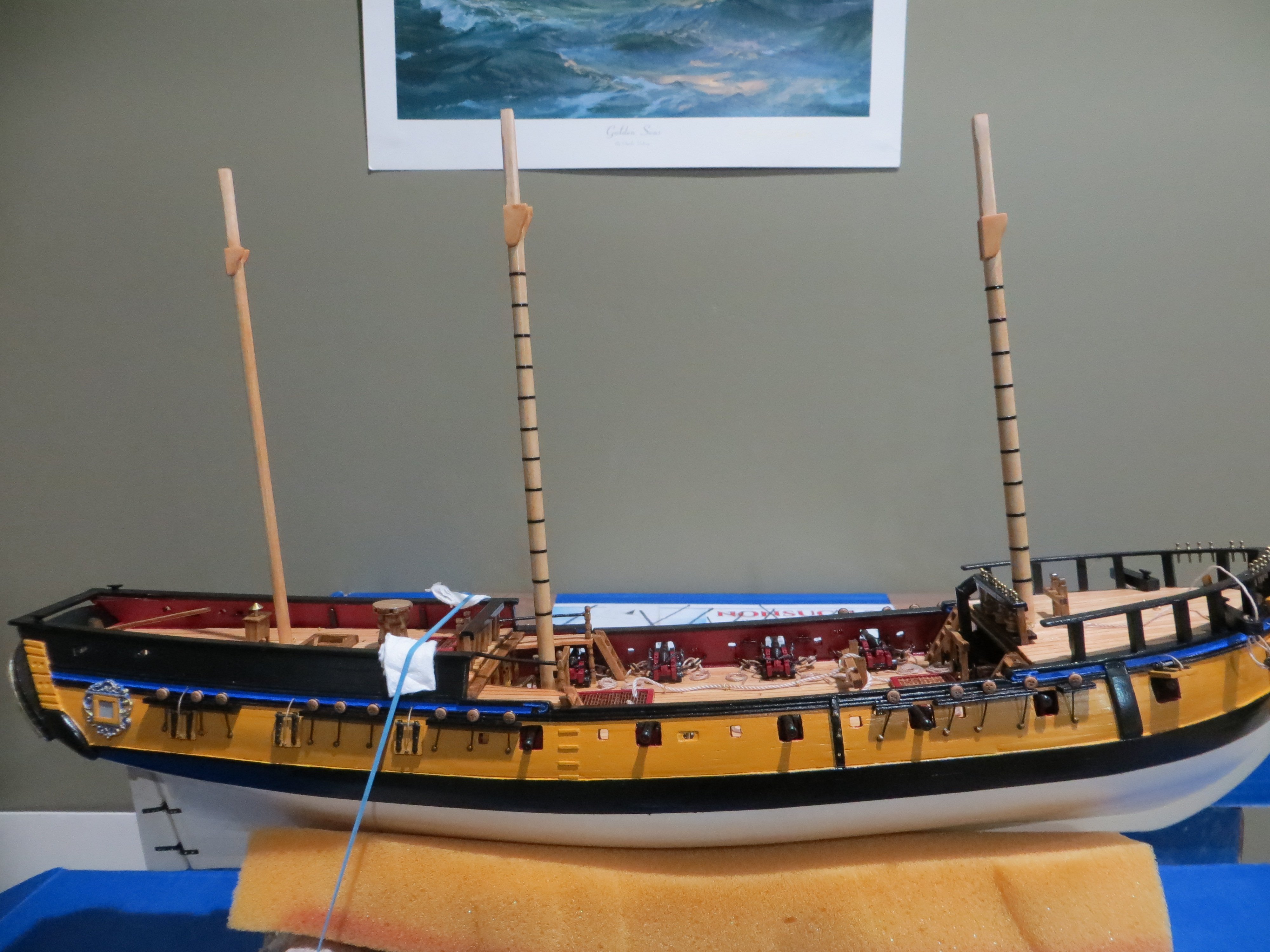
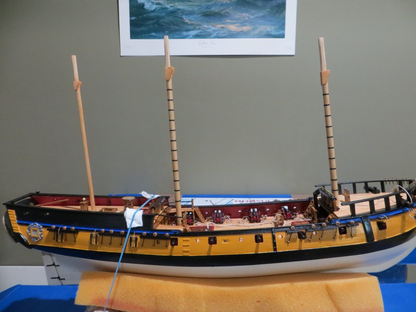
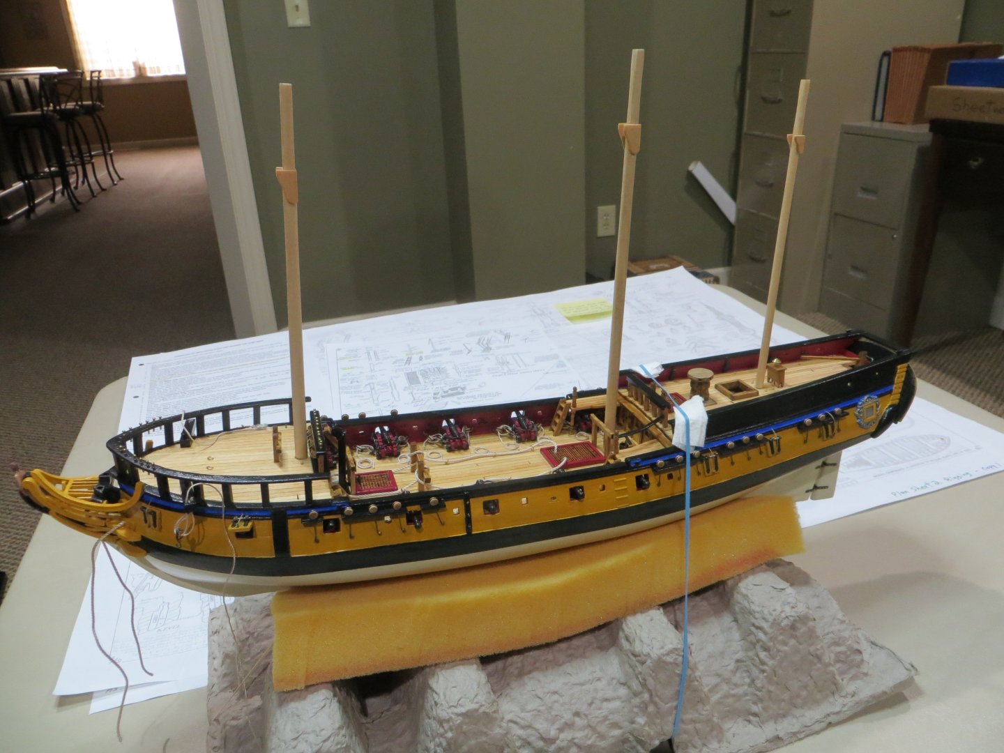
RATTLESNAKE – MASTING & RIGGING PROCESS I've reached a MAJOR milestone! After 2 years and 4+ months, I’m finally starting on the masting & rigging of my Rattlesnake! I bought Robert Hunt’s Practicum (Lauck Street Shipyard) on Rigging the Rattlesnake to help me with this challenging aspect of this ship build. Bob wrote this as a stand-alone course that is also part of his kit bash of the 3/16” scale (1:64) Mamoli kit. However, his kit bash is based on Harold Hahn’s plans which is based on a ¼” scale (aka 1/48th ). When he references the Hahn plans it requires a 74% reduction. This should not be a problem for following Hunt’s rigging instructions. But it’s important to know this when he references Hahn’s plans. I’m also following the Rattlesnake build log by Jon Gerson on this site. Jon did an excellent job of logging his 3/16” Mamoli kit using Hunt’s full practicum. I’m not doing the kit bash version, so I ignore these steps. But everything else Jon does is super helpful. He also identifies some errors in Hunt’s course that can save some headaches. Now back to my Model Shipways Rattlesnake build. I do not plan to rig with sails. I want to show the rigging lines unobstructed. The instructions even say that this model kit is intended to be built without sails. According to the manual, most modelers do not install bunt and leech lines, or reef tackle, and their blocks, and most all of the sheets for fore and aft sails are omitted. In port, yards would be lowered on their lifts. See the manual for more details on these items. Making the Lower Masts There are three masts, fore, main and mizzen. The fore and main are built identically and except for mast length are the same dimensions in terms of diameter and mast tops. The mizzen mast does not include a topgallant section so its construction is different. The practicum builds the masts start to finish one at a time. Since the dimensions for the fore & main masts are virtually identical, I’m going to build them together. I’m also making the lower mast for the mizzen now. I may not continue and/or keep up with it though. Partly because I ran out of stripwood for the mizzen mast top. I am waiting for a shipment from Model Shipways to arrive. I cut the fore & main mast from a ¼” dowel. The fore mast needs to extend 7” above the focsl deck. An additional 1 – 9/16” is required on my model for the depth from the focsl deck to the bottom of the hole. The main mast must extend 8-1/2” above the deck. Another 5/8” is required below the deck. The mizzen is made from a 3/16” dowel. My ship requires 1-3/4” below the quarter deck. Above deck is 6-7/8” long. Each of the masts has a square section at the top of the lower mast. Unfortunately, the length of this square area according to the practicum is different than the MS blueprints. I struggled with this for a while and then decided I just had to follow one or the other. I decided to follow the practicum. One of the challenges with the masts is making sure everything is squared up; fore to aft and side-to-side. I placed the mast in a vise and carefully marked the top of the mast with the square pattern required. Then I used my mini-plane to shave the top half to three-quarters down to the mark. The plane cannot be kept level as wood is removed, so the bottom had to be hand sanded. Here is my set-up for this step: Fore & Main Masts squared off from ¼” to 3/16” Cheeks – The cheeks hold the mast tops in place. The practicum says the next step is to cut the corners off a portion of the square section to turn it into an octagon. And then to flatten the area below the square on two sides for the cheeks. But I thought it would be better to make the cheeks first for marking off the area required to be sanded flat. I made a tracing of the cheeks and cut them out from a wide piece of 1/16” thick stripwood. The forward and bottom edges are supposed to be rounded off. The octagon cut and flattened area completed on one mast Test fitting the Cheek on the mast The Cheeks are glued to the mast The masts also need to be tapered slightly from starting halfway up to just under the cheeks. I did this with sandpaper. This is not easy to do by hand since the masts are made from some harder wood than basswood. I stained them with Minwax Natural. I plan to add a coat of poly once I put the mast rings on. Here is a picture of the ship with the 3 masts test fit in place. I’m making the mast tops now. I will post on that when completed. I’ve got a question for you guys. When do you put your ship in its permanent stand? I waited until I was close to completion with Bluenose. I’d like to get it out of this cardboard cradle, but I’m afraid of damage to the keel from the posts during the rigging process. The holes were pre-drilled. What do you guys think??? Thanks, Ed
-
Thanks John! I enjoy doing it.
-
Thanks Dave! The ship's longboat is such a prominent feature on the deck of the Rattlesnake, I wanted to do it justice. This little kit didn't cost much and it looks much better than the one that comes with the ship. It was a small project however! It took me 60 calendar days and 120 hours to build. I think it was worth the effort.