HOLIDAY DONATION DRIVE - SUPPORT MSW - DO YOUR PART TO KEEP THIS GREAT FORUM GOING! (Only 36 donations so far out of 49,000 members - C'mon guys!)
×

Ed Ku20
-
Posts
230 -
Joined
-
Last visited
Content Type
Profiles
Forums
Gallery
Events
Everything posted by Ed Ku20
-
 Dave, I'm sorry to hear that you are starting over on your Half Hull build. It takes a dedicated modeller to start over when things aren't up to your standard. Thanks for the tip on the 280 grit buff. I just bought one based on your post. I too have had issues using the sanding drum on char. It is very difficult to control! Best of luck on build #2! Ed
 -
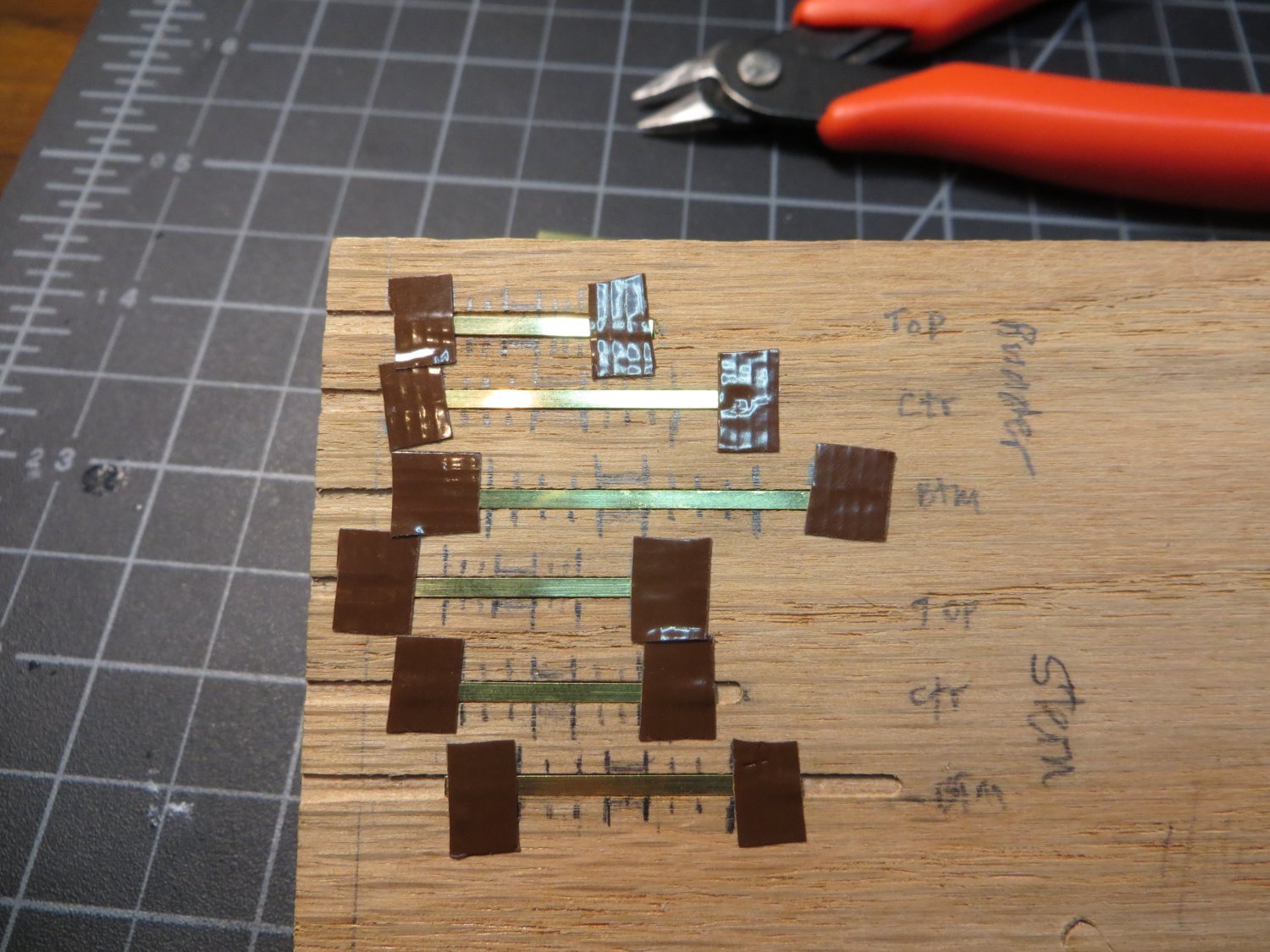
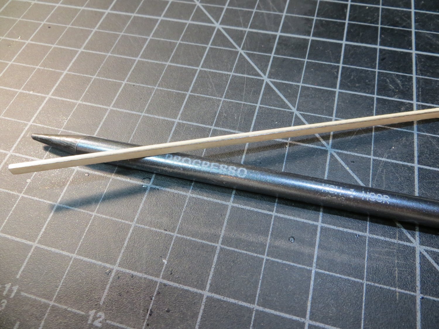
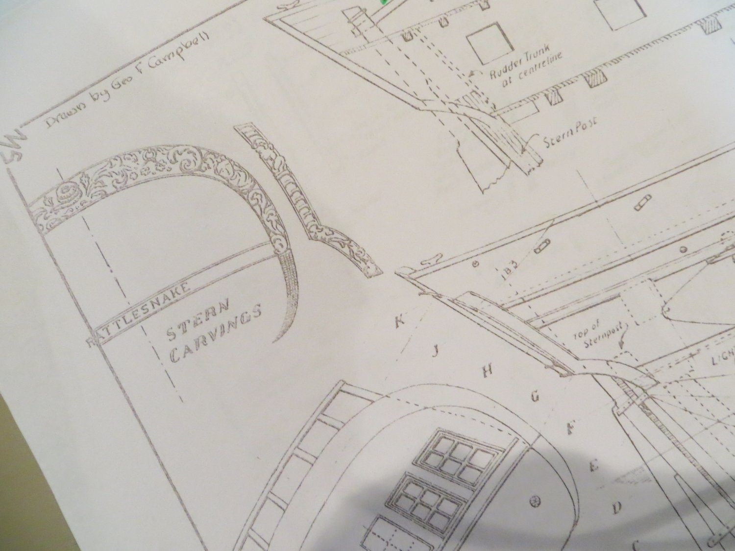
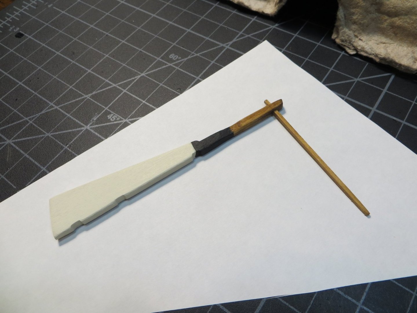
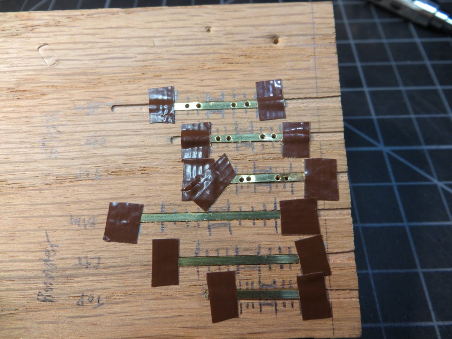
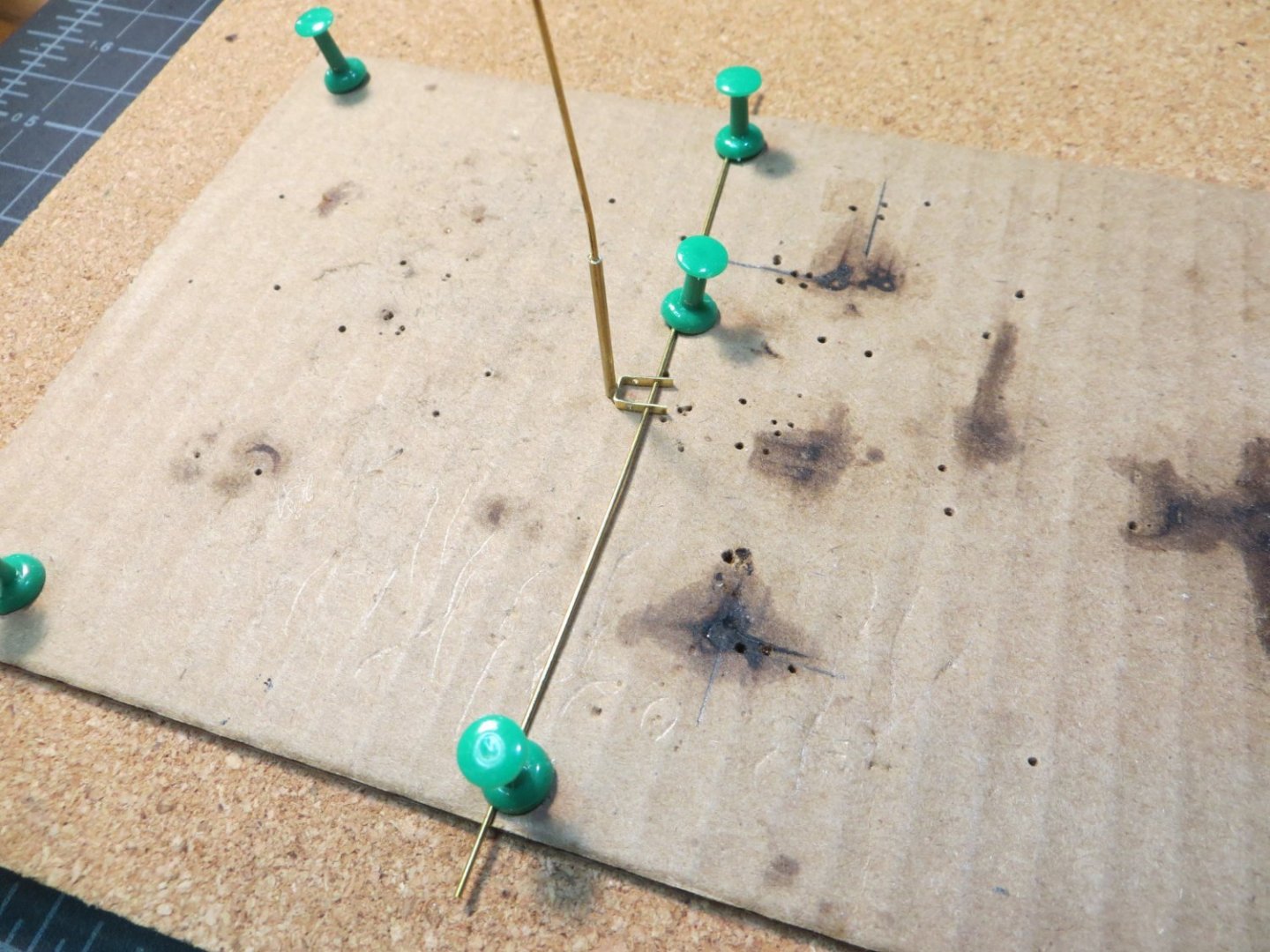
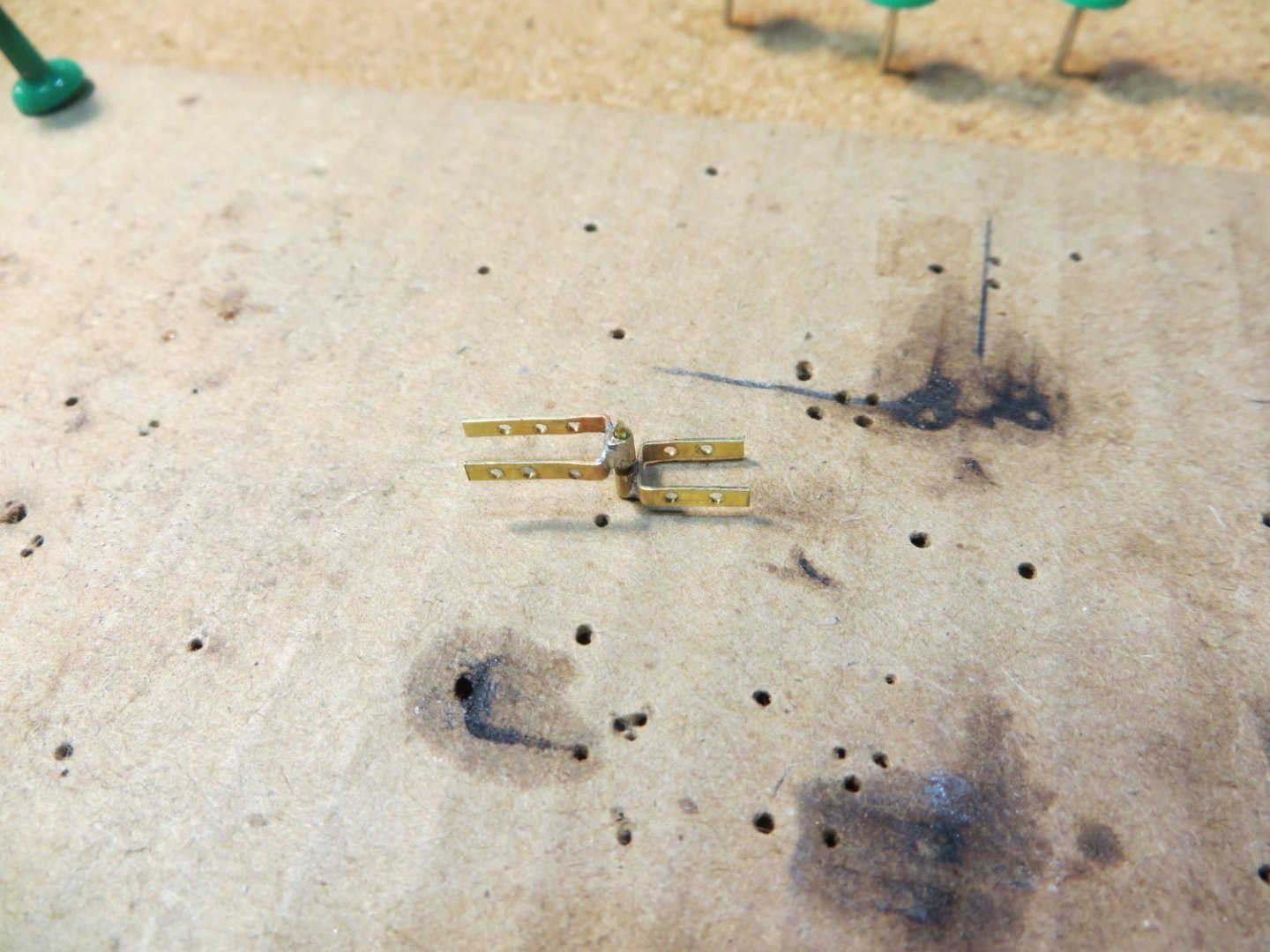
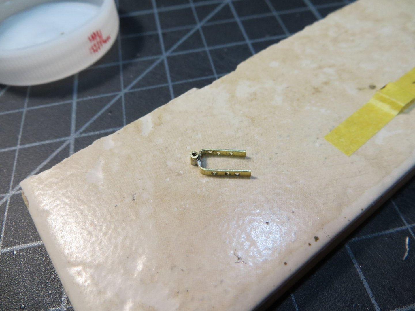
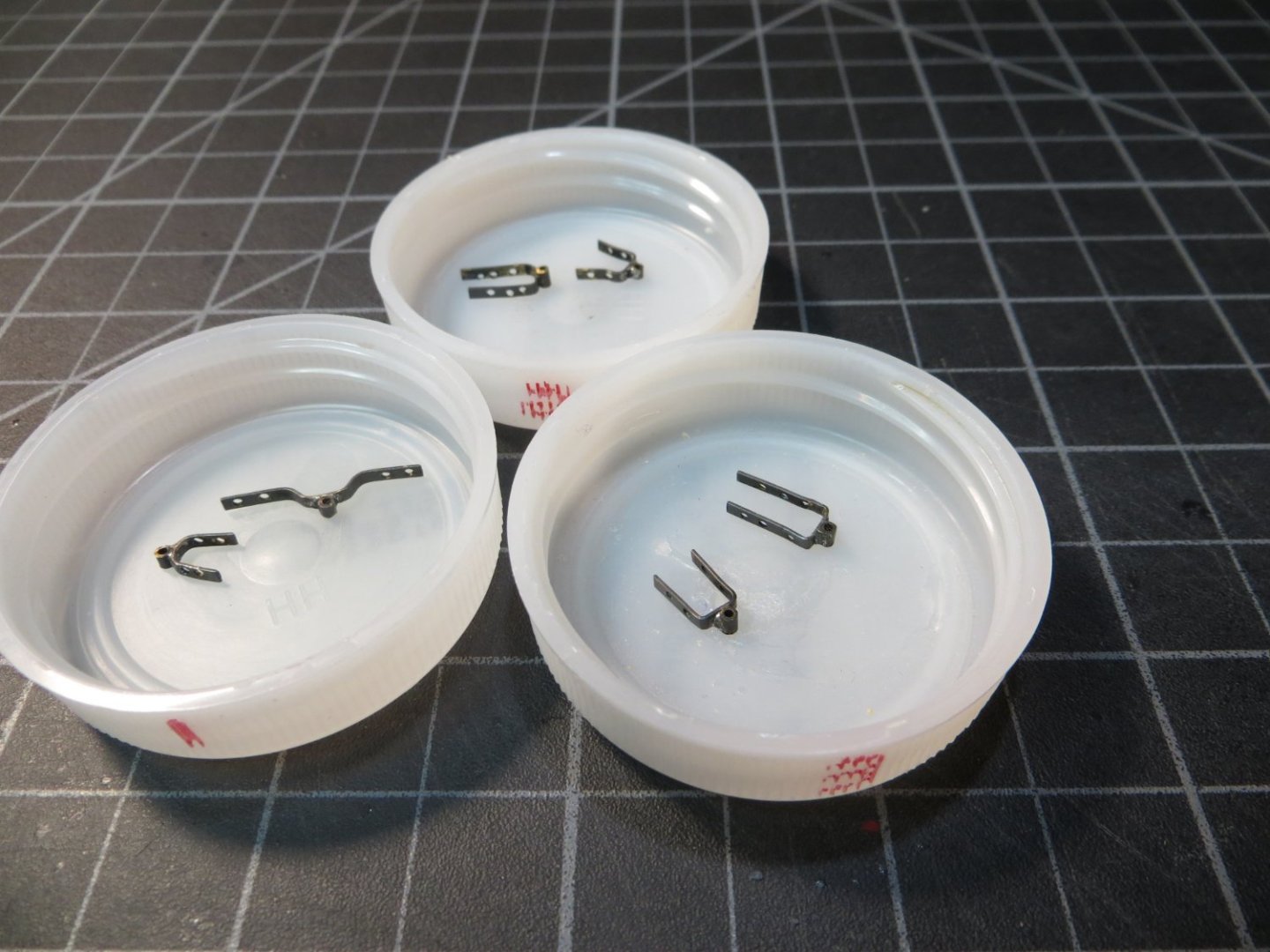
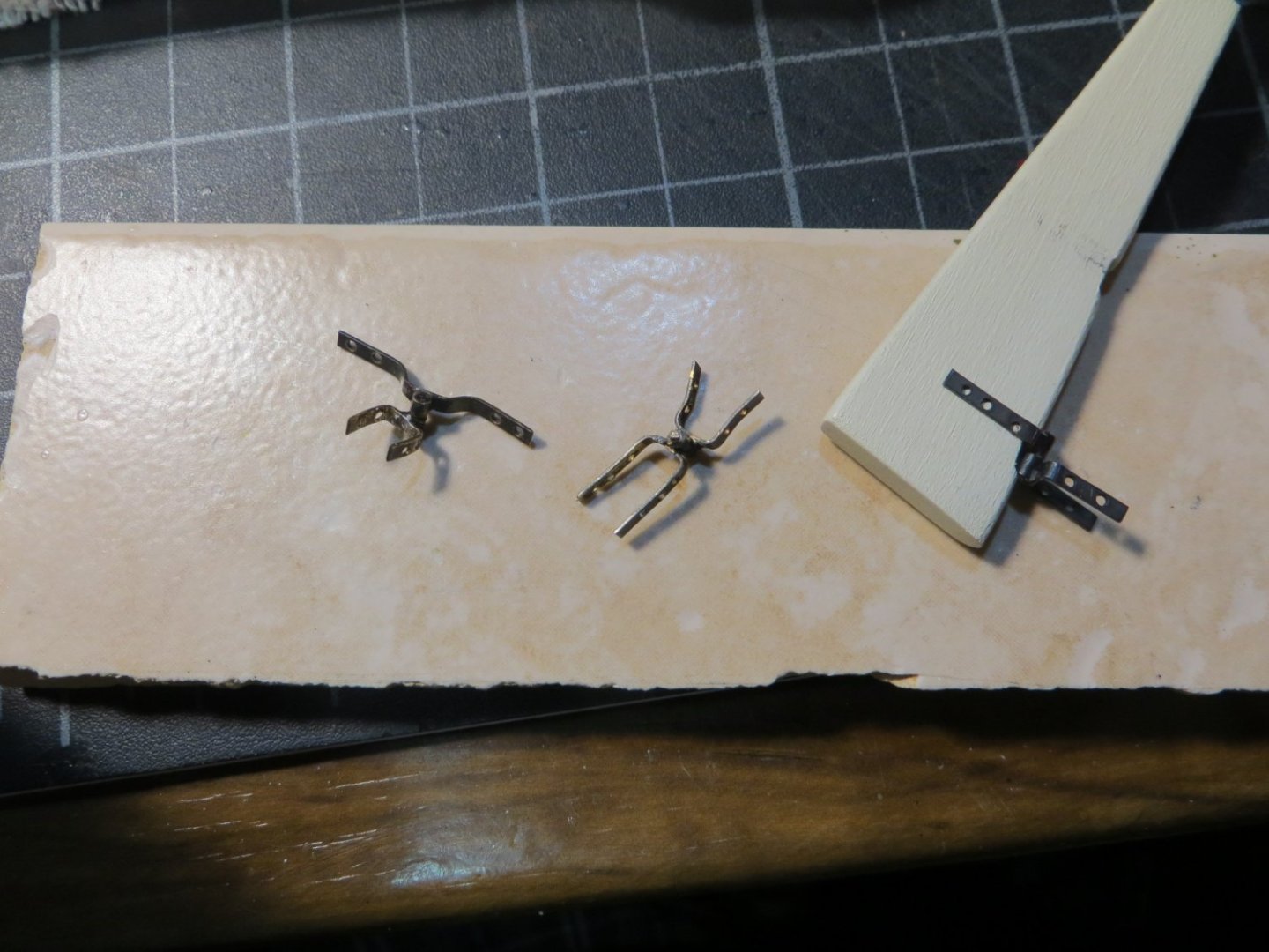
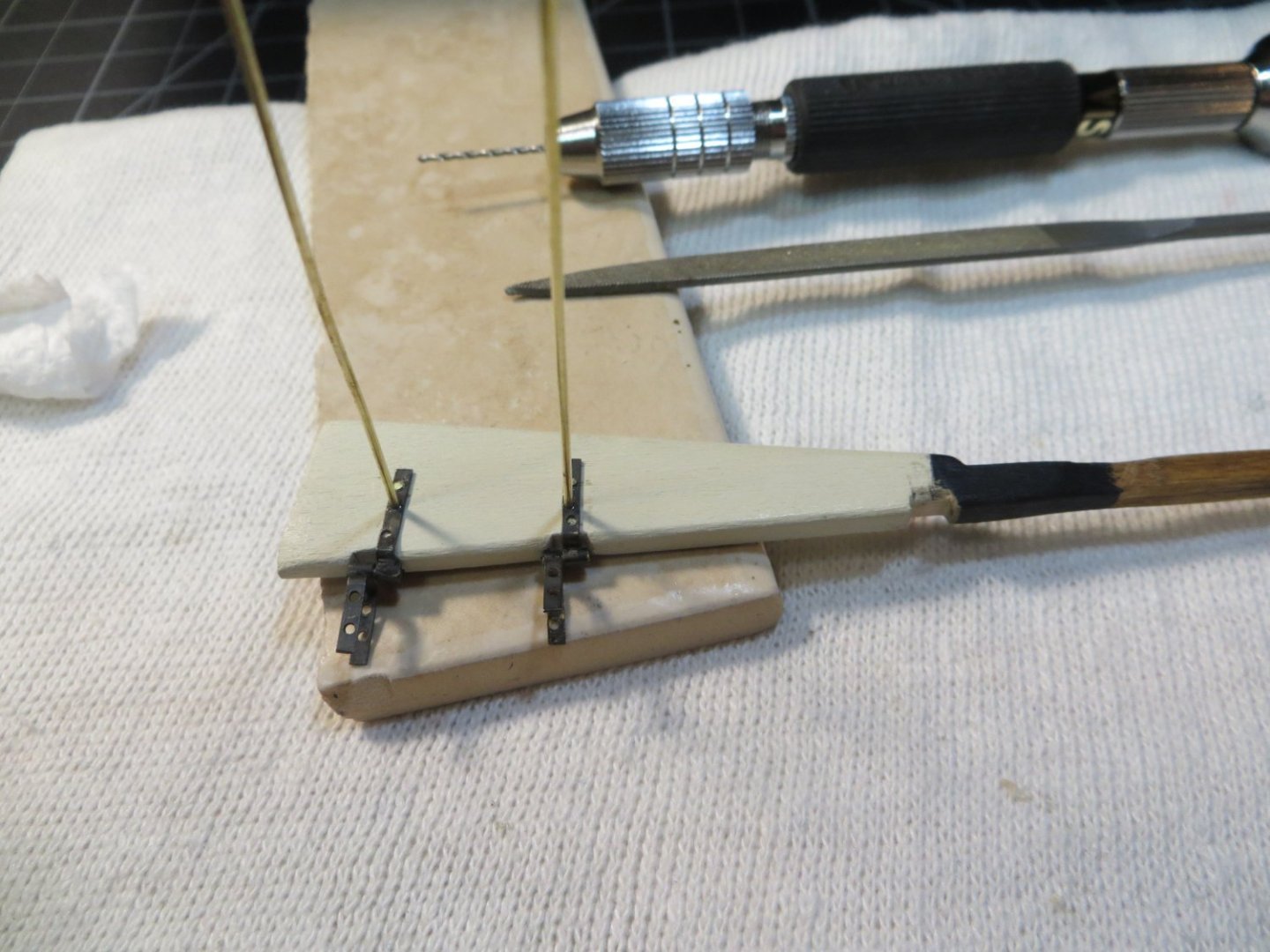
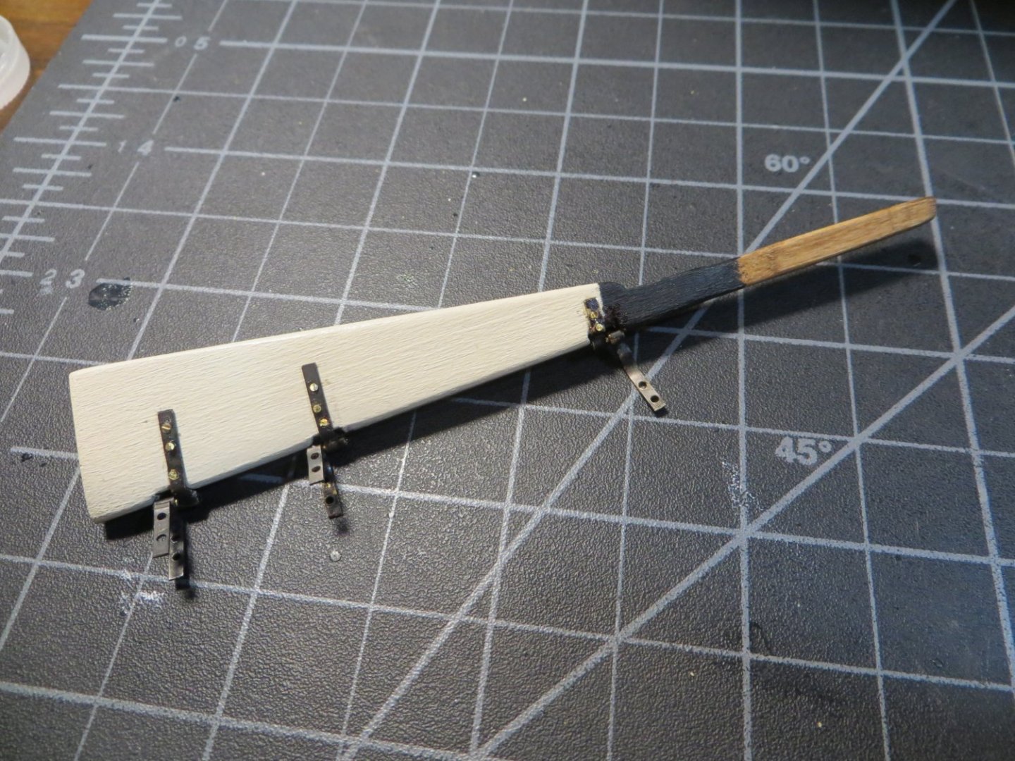
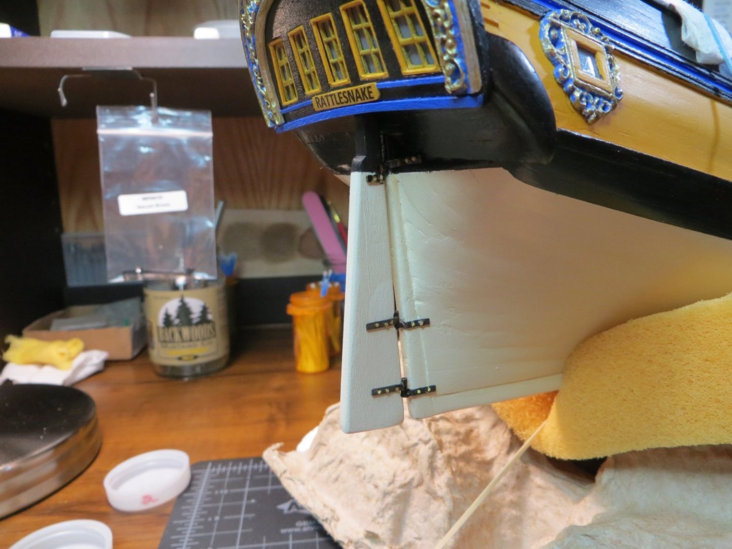
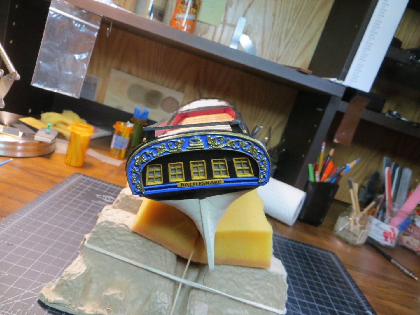
Rudder & Tiller The Rudder is provided as a laser cut part in the Rattlesnake kit. It requires clean-up to remove the laser char. The rudder must be tapered along the forward edge with no taper at the top to 5/32” from the middle to the bottom. I used a square piece of strip wood for the tiller. A hole is drilled in the top of the rudder stem to slide the tiller through. Do not glue the tiller to the rudder yet! You have to slip the rudder up through the hole at the stern before inserting the tiller into the hole. This is done as the last step. I did not bother to use any glue. It was a snug fit. I dry-fit the rudder and marked where the white and black painted sections of the hull cross the rudder. I hand painted both of these colors. I decided to stain the top of the rudder and the tiller with Golden Oak to match the coamings. Here it is afterward. The next step is to make the Pintles & Gudgeons hardware for attaching the rudder to the hull. The pintles are on the hull side and the gudgeons are on the rudder side. On my Bluenose build I made the rudder so the hinge was free and it could turn from side to side! Unlike Bluenose, the rudder stem goes all the way up to the deck. It does not turn much, unless you sand down the entire stem of the rudder. I used the brass strip that came with the kit to make this hardware. The process begins with meticulous measurements to identify where to drill the holes in the strips for attaching to the hull/rudder. I made a build board with shallow dado cuts to hold the strips while using the drill press to make the holes. Some people say they use rubber cement to hold the strips down. This did not work for me with Bluenose. Gorilla tape works pretty good. Brass strips ready for the drill press: The 3 strips for the Stern post with holes drilled using a #64 bit: After drilling the holes it’s time to bend the strips and solder 1/16” pieces of tubing to the middle of each one. I really struggle with soldering. The hardest part for me is holding the parts together, without them moving, while pushing the tip of the iron against the part and moving it out of position!!! Ahhh! Insert expletive! One of the parts ready for soldering. The problem with this setup is it’s hard to saw off the excess tubing close to the strip and without crushing the tube. I switched to cutting the tube before soldering after this: One of the brass strips and tubes assembled: Here is a completed piece of hardware with tubing soldered to both brass strips and a 0.032” rod inserted to connect the tubing. After installation on the ship, I placed a drop of CA glue in each tube: After all the parts were assembled, I treated them with brass blackening chemical. Here are the 3 sets ready to install: Dry fitting the parts on the rudder and stern: I used 0.032” brass rod to attach the pintles & gudgeons. I dipped the tip in thick CA glue, which squeezed out under the strip as well as in the hole. The excess rod was trimmed off tight to the part: Rudder attached. I touched up the paint after this picture. I still need to apply a coat of wipe-on poly for protection: Rudder stem with Tiller attached. I plan to add a couple of more coats of Golden Oak to darken the tiller: The finished view of the stern! The step I'm working on now is making the Hatches & Gratings. Thanks, Ed


-
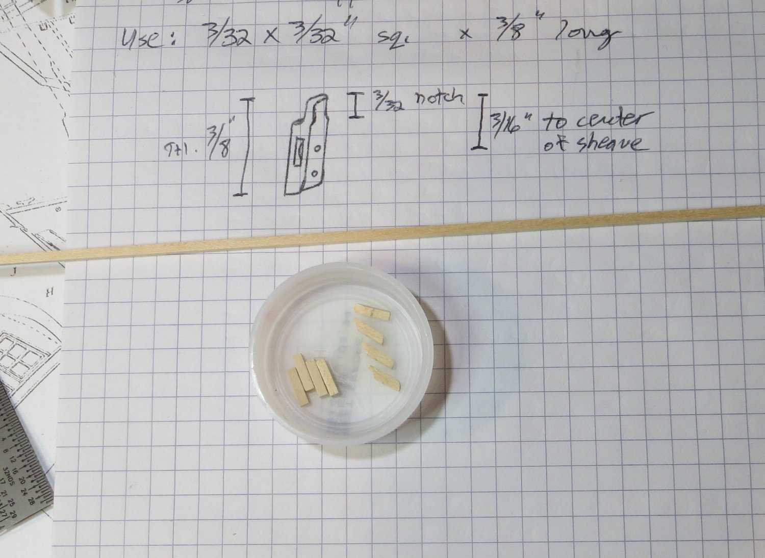
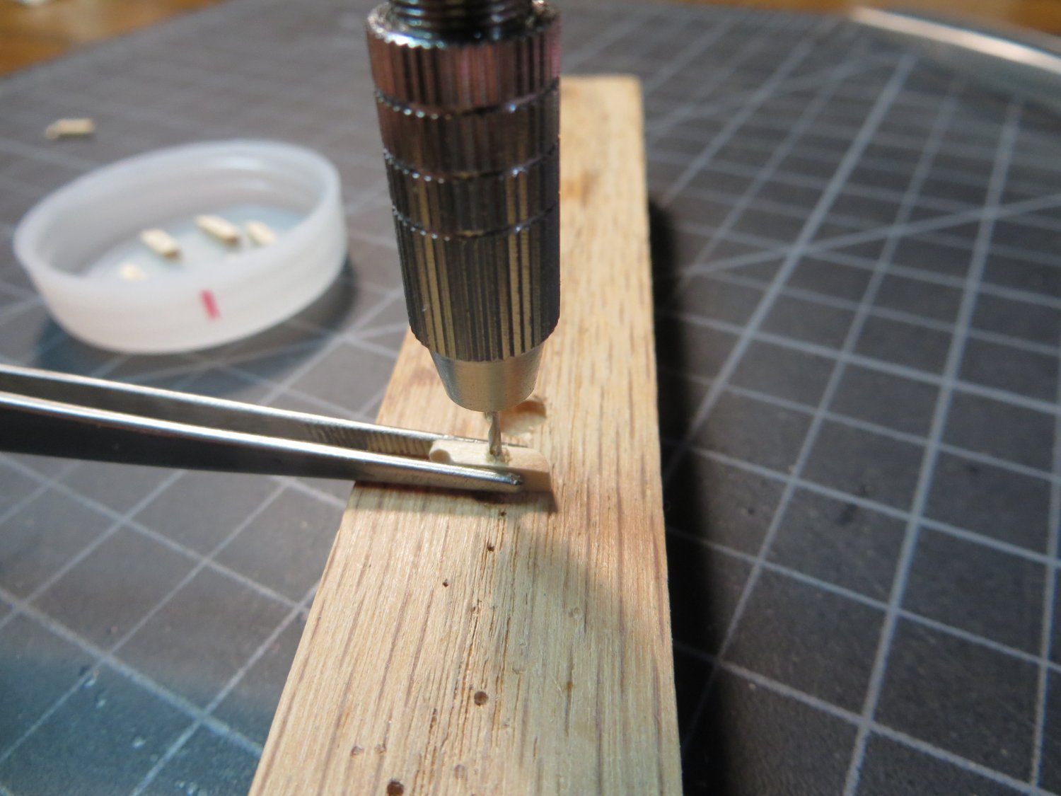
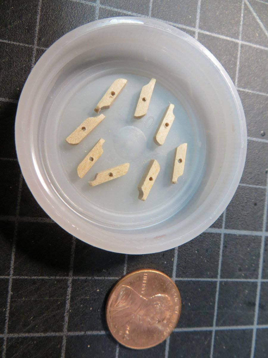
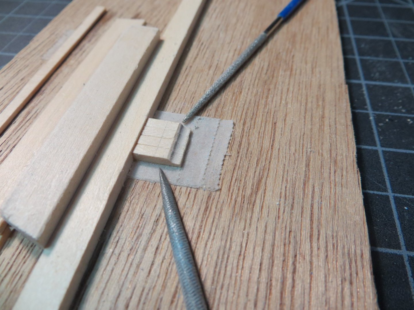
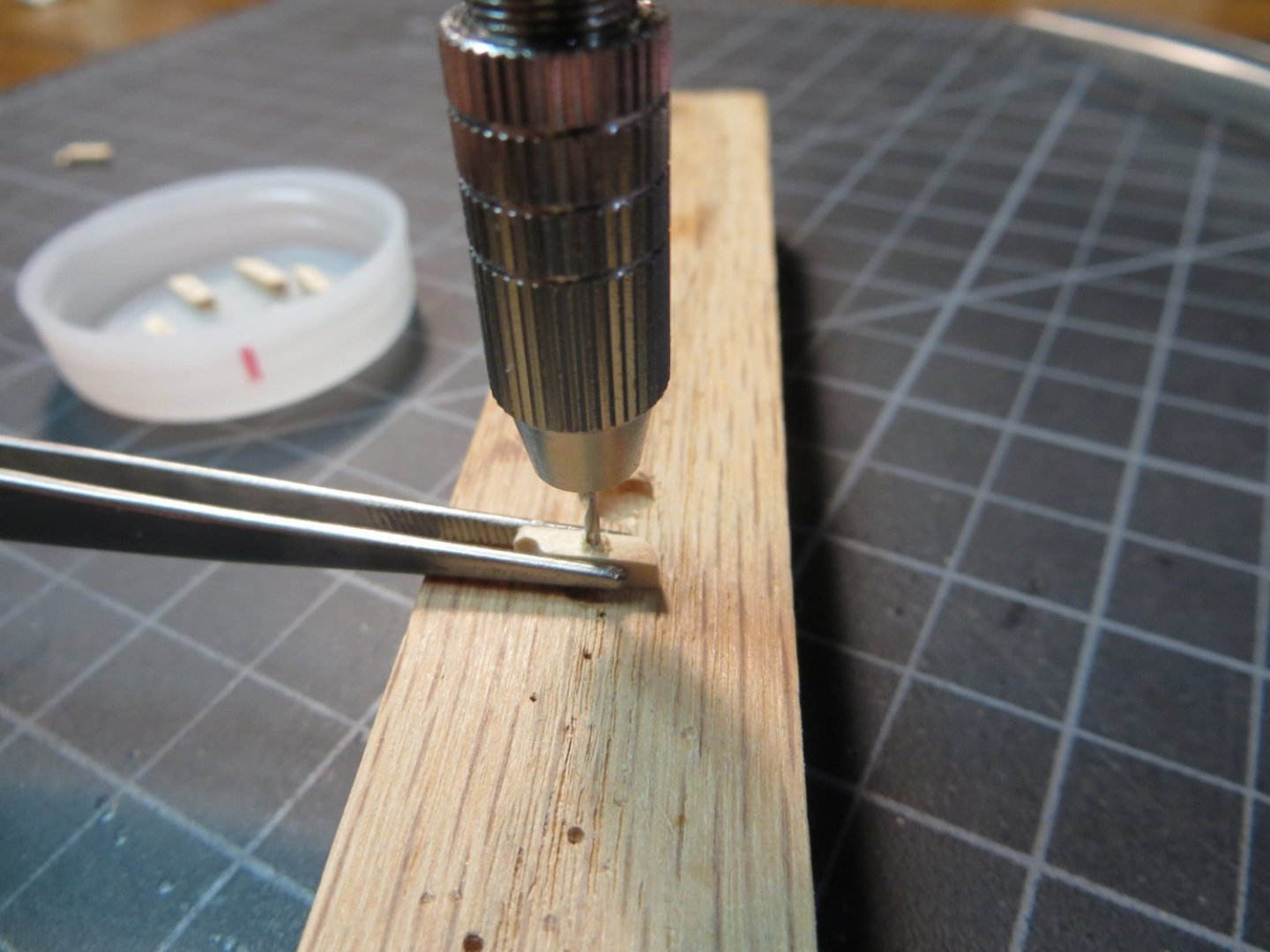
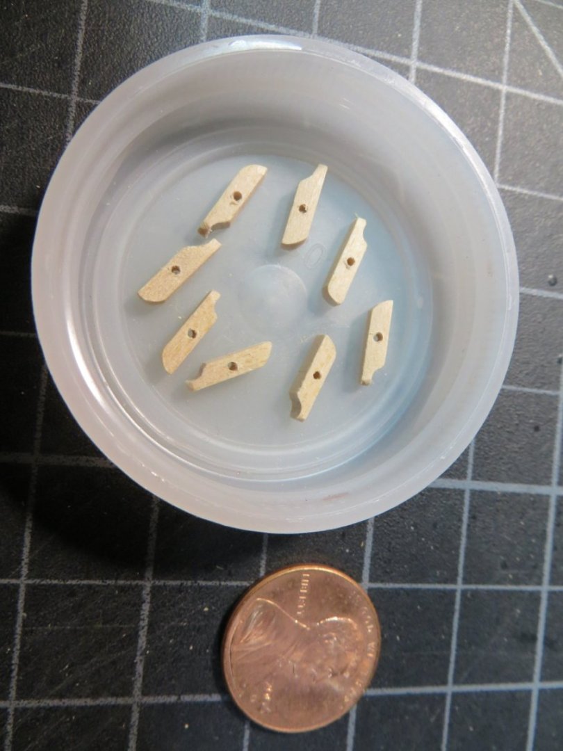
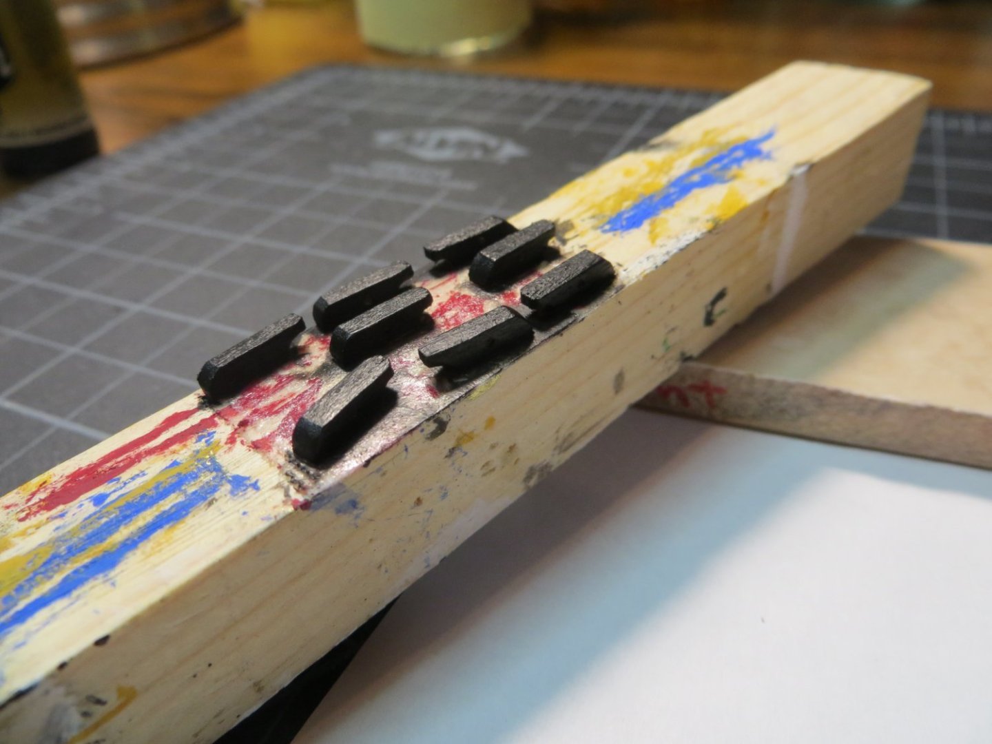
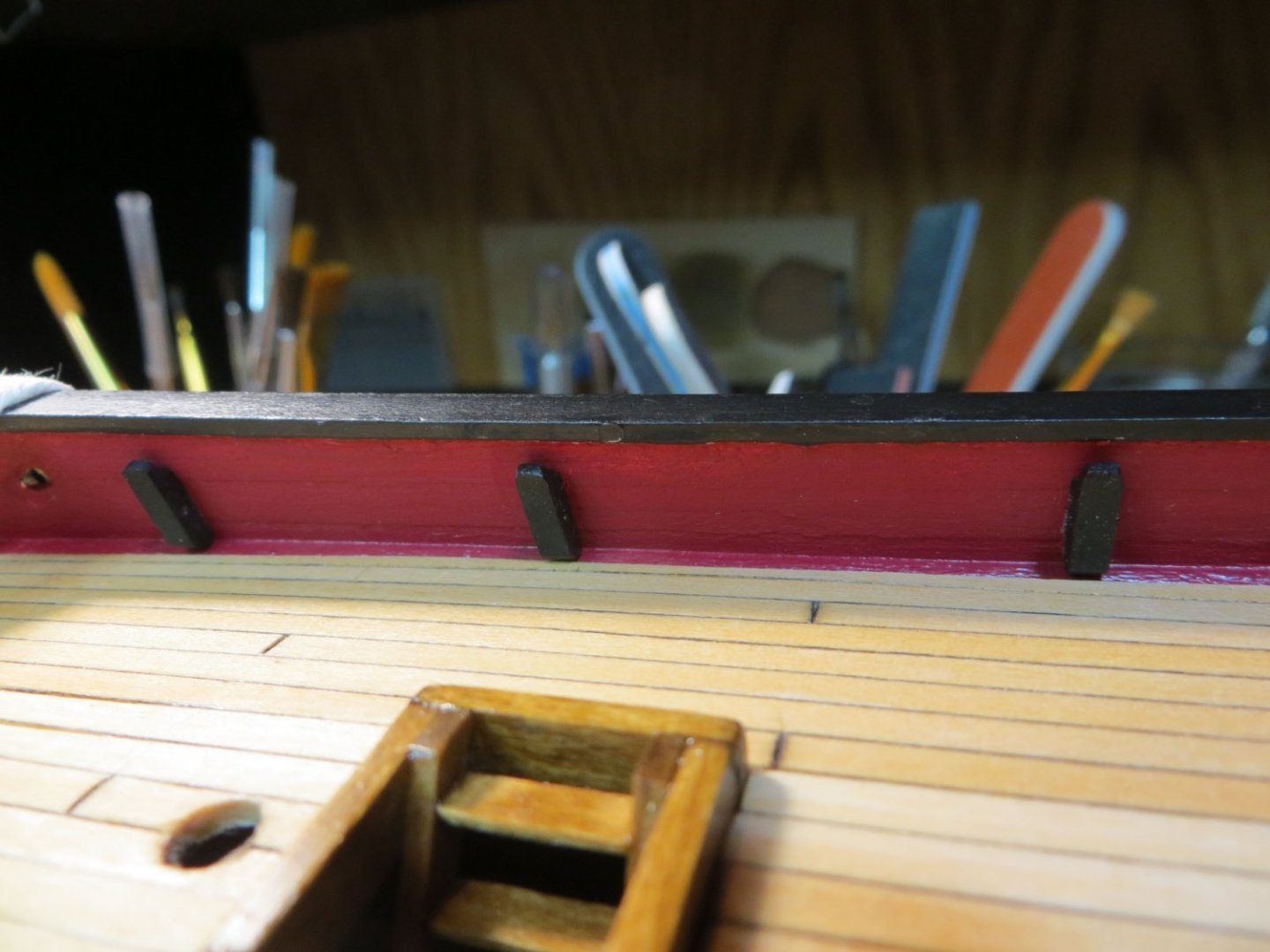
Make & Install 8 Kevels I have another quick update. The plans call for making 8 Kevels from stripwood. These are similar to the Chesstrees we attached to the outboard side of the hull bulwarks. Except they go on the inboard side of the bulwarks. 6 of them go on the quarter deck. 2 more kevels are attached to railing posts on the focsl. I made all of them now, but will not add the last 2 until the focsl railings is completed. Here is the process I used. I cut 8 pieces of stripwood from this 3/32” x 3/32” piece shown below I used one of my old jigs to hold down 4 of them down at one time while I sanded the curved bevel that is at the top of the kevel. I used these round files to do the job Since these are pretty hard to see on the inside of the bulwark, I decided not to insert a detailed sheave like on the Chesstree. I just drilled a hole in the side, which is suggested in the manual I rounded off the bottom edge and cleaned everything up with sanding sticks I used my double-faced taping stick to hold them down while I painted them black. The tape also keeps the glued edge clean for better adhesion Here are the 3 kevels glued in place on the port side of the quarter deck My next step is making the rudder & tiller and attaching it to the ship using Pintles & Gudgeons. Thanks, Ed

-
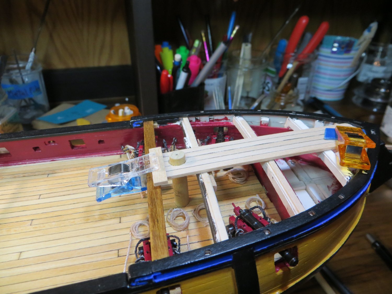
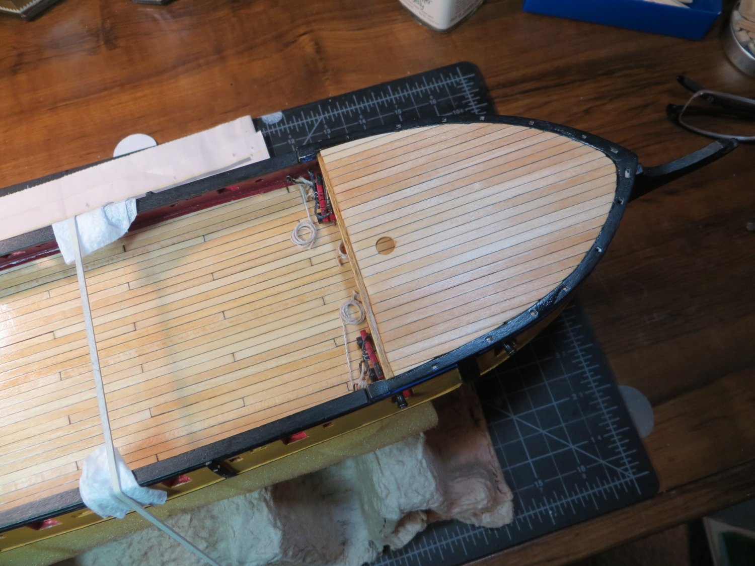
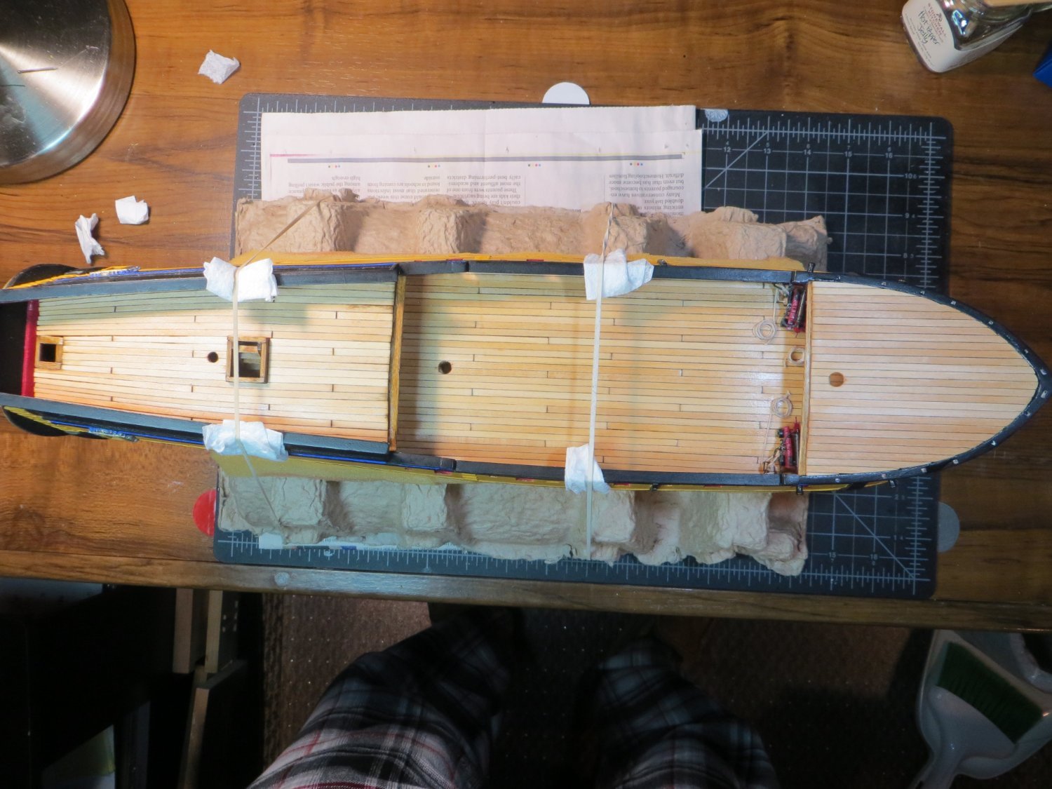
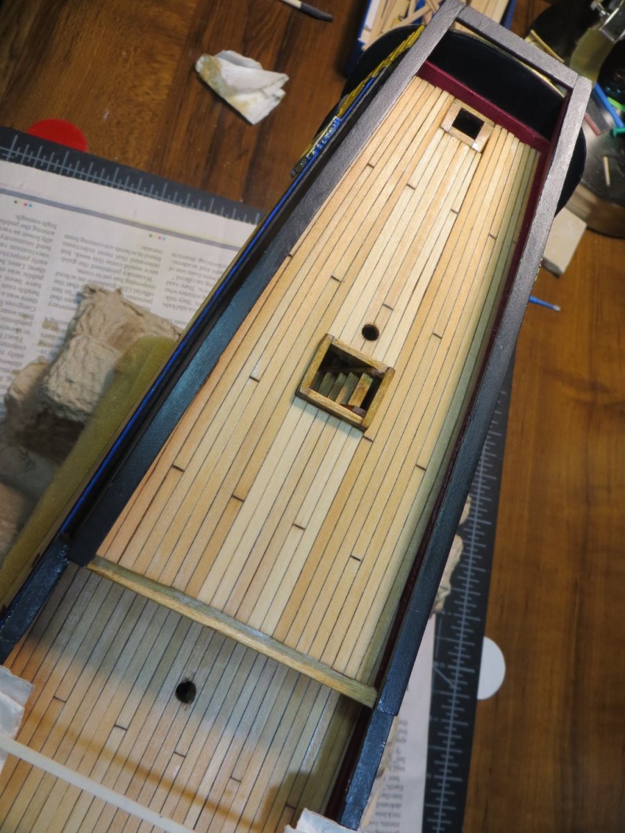
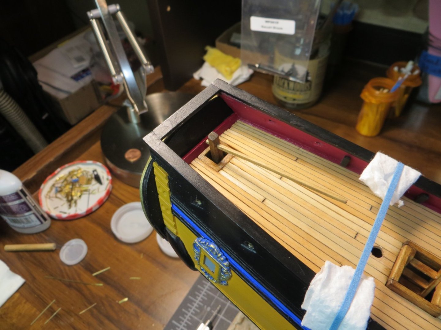
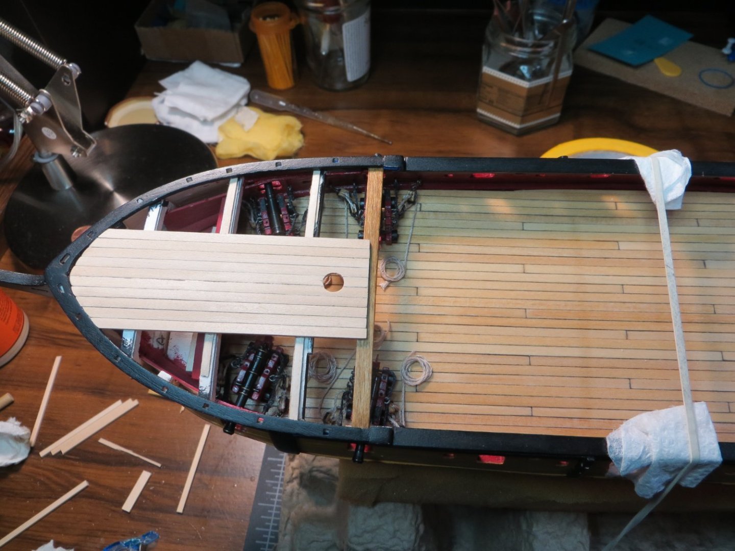
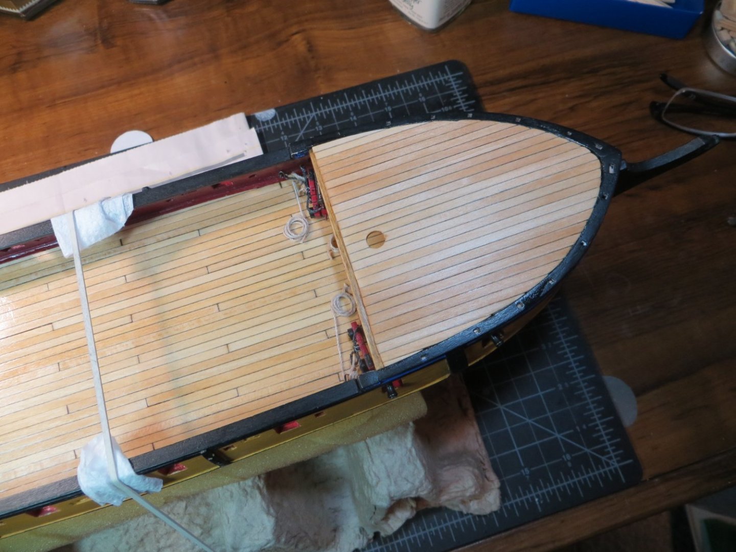
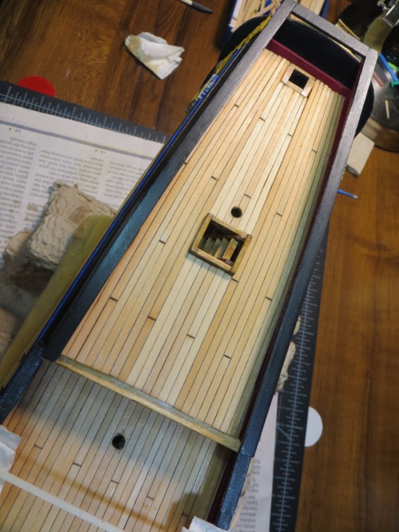
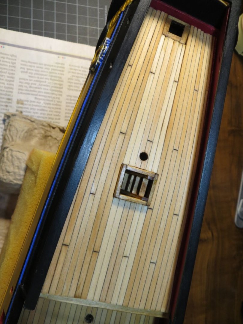
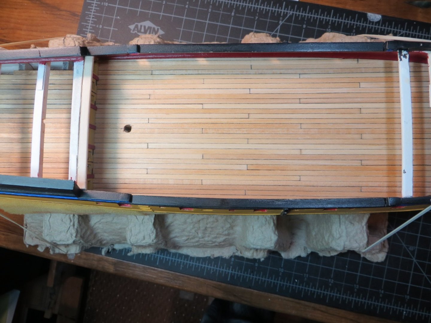
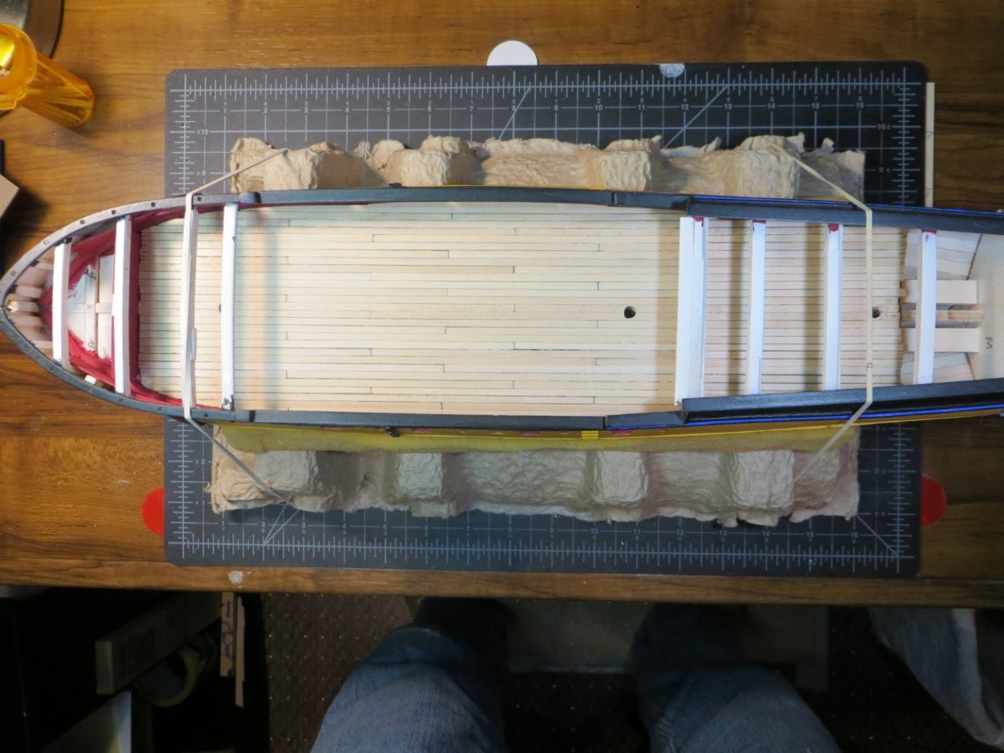
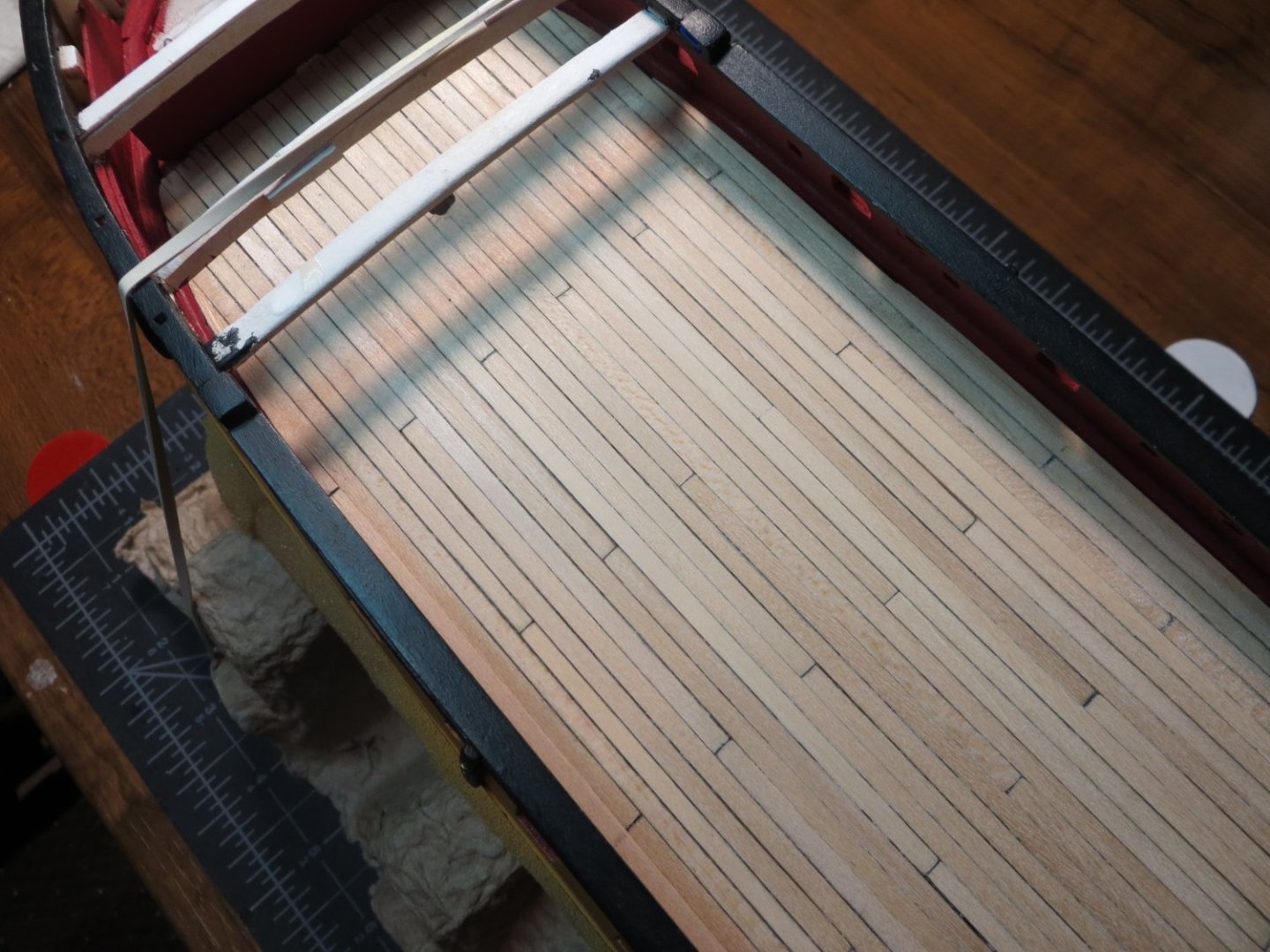
Planking the Focsl Deck Another milestone has been reached in the building of my Rattlesnake. The Focsl Deck planking has been completed. This means all the decks are finished! I had a couple of steps to complete before I started planking. · I was not happy with the original focsl deck beam. I painted it black a while ago and then decided to stain the quarter deck beam with Golden Oak. Now the black beam didn’t look so good! So, I removed the black beam and replaced it with a new one that I stained the same color as the q-deck. When I made the focsl beam a while back, I did not have the Artesena scrappers that I used on the q-deck beam. I used them to create the same fancy groove on the aft side. Now, both beams match. · Next, I drilled out the hole for the fore mast in the gun deck to the full ¼” size that it needs to be · I also added some supports at the bow to hold the planks up on that end Now planking commenced! I learned from my mistake with the mizzen mast holes. This time I cut a short stub of ¼” dowel. I edge glued 5 planks together that were sized to fit down the center of the focsl. I placed a round piece of double-faced tape on top of the mast stub. I pressed the section of deck on top of the mast so the tape stuck to the underside of the deck. This is the spot where I needed to drill the hole for the mast! This worked very well. Below is the section of deck dry-fitted in position with the mast stub not fully inserted into the gundeck hole I applied glue and used a longer piece of mast to keep everything aligned while the glue dried Since the focsl deck is shorter, no butt joints are needed. The planking continues. My wife couldn't understand why I spent so much time building cannons that no one would be able to see! The finished deck after staining with Minwax Natural A birds-eye view of all the decks when finished Next step is making and installing the 8 Kevels that go on the inboard bulwarks. Thanks for looking in! Ed


-
Hey John, Best of luck with your move. Hopefully everything goes smoothly and quickly for you! Make sure the rental has room for your workshop!
-
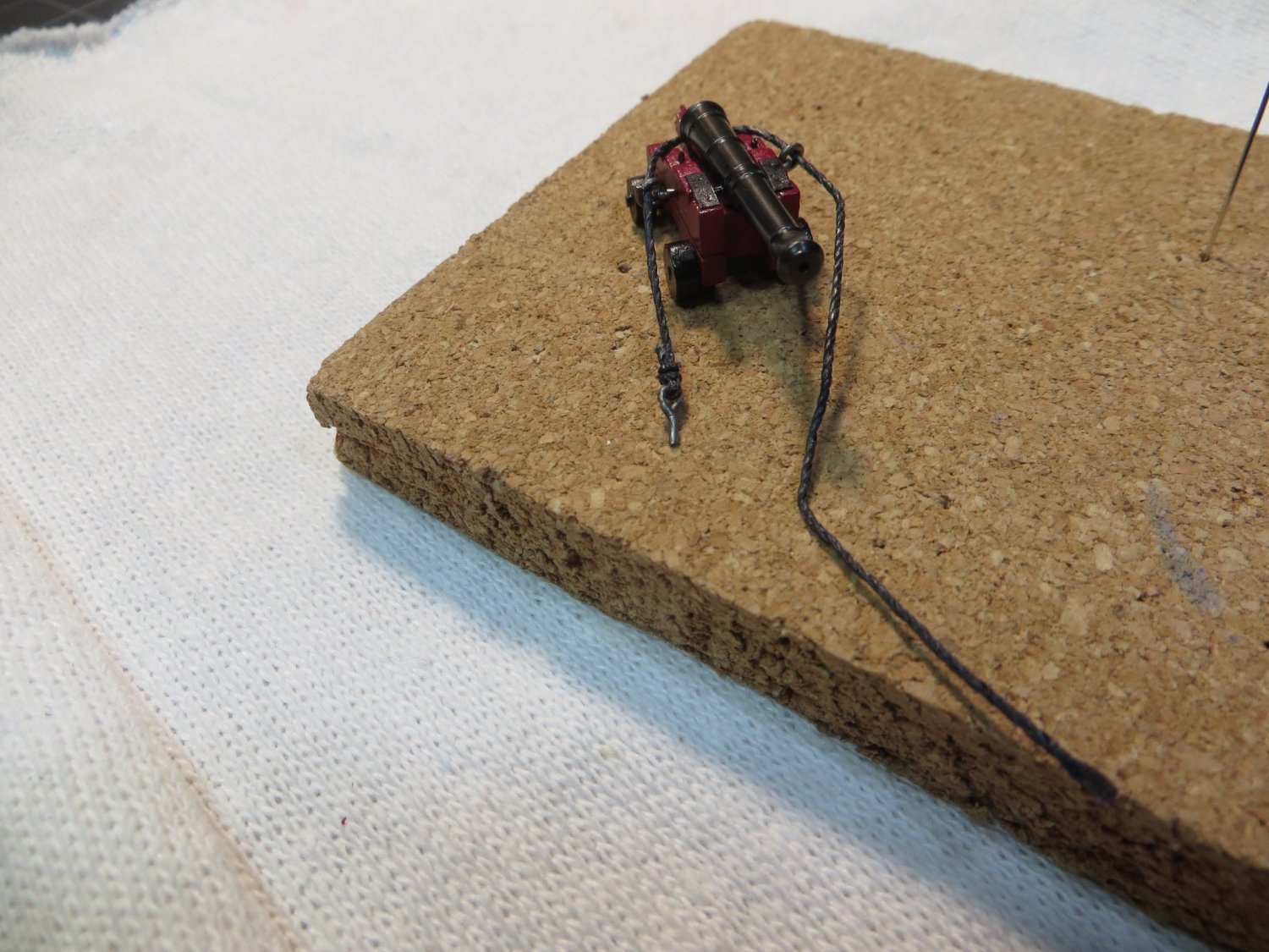
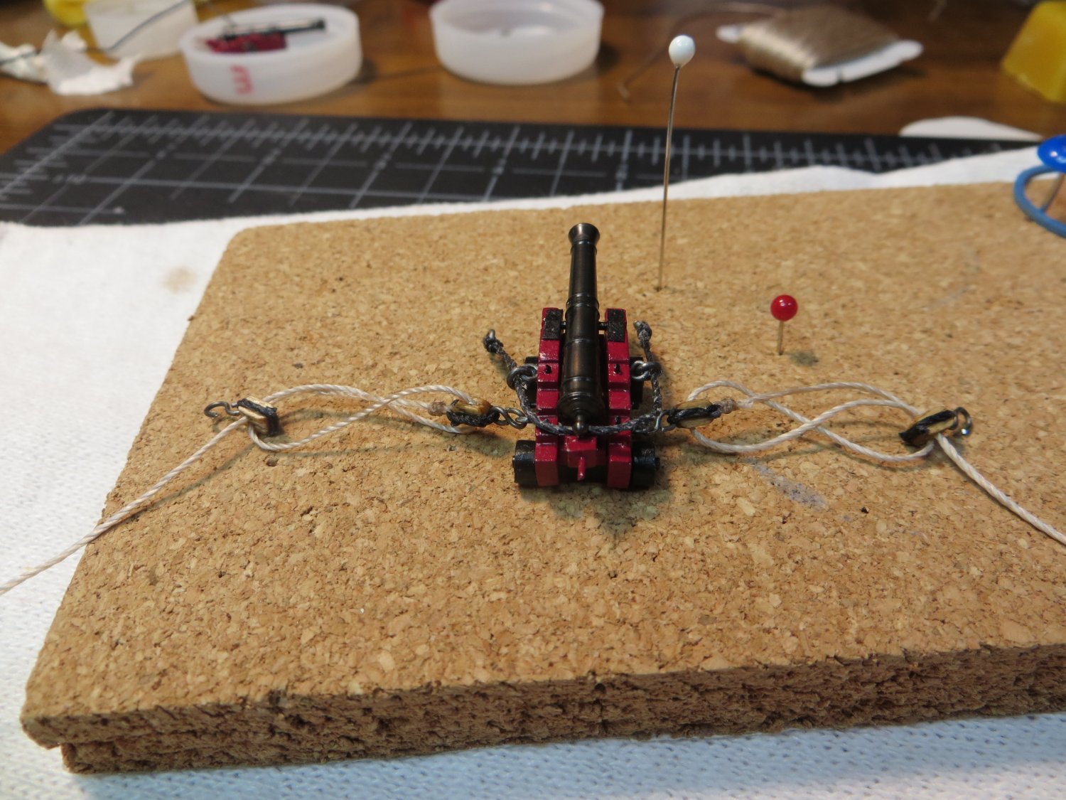
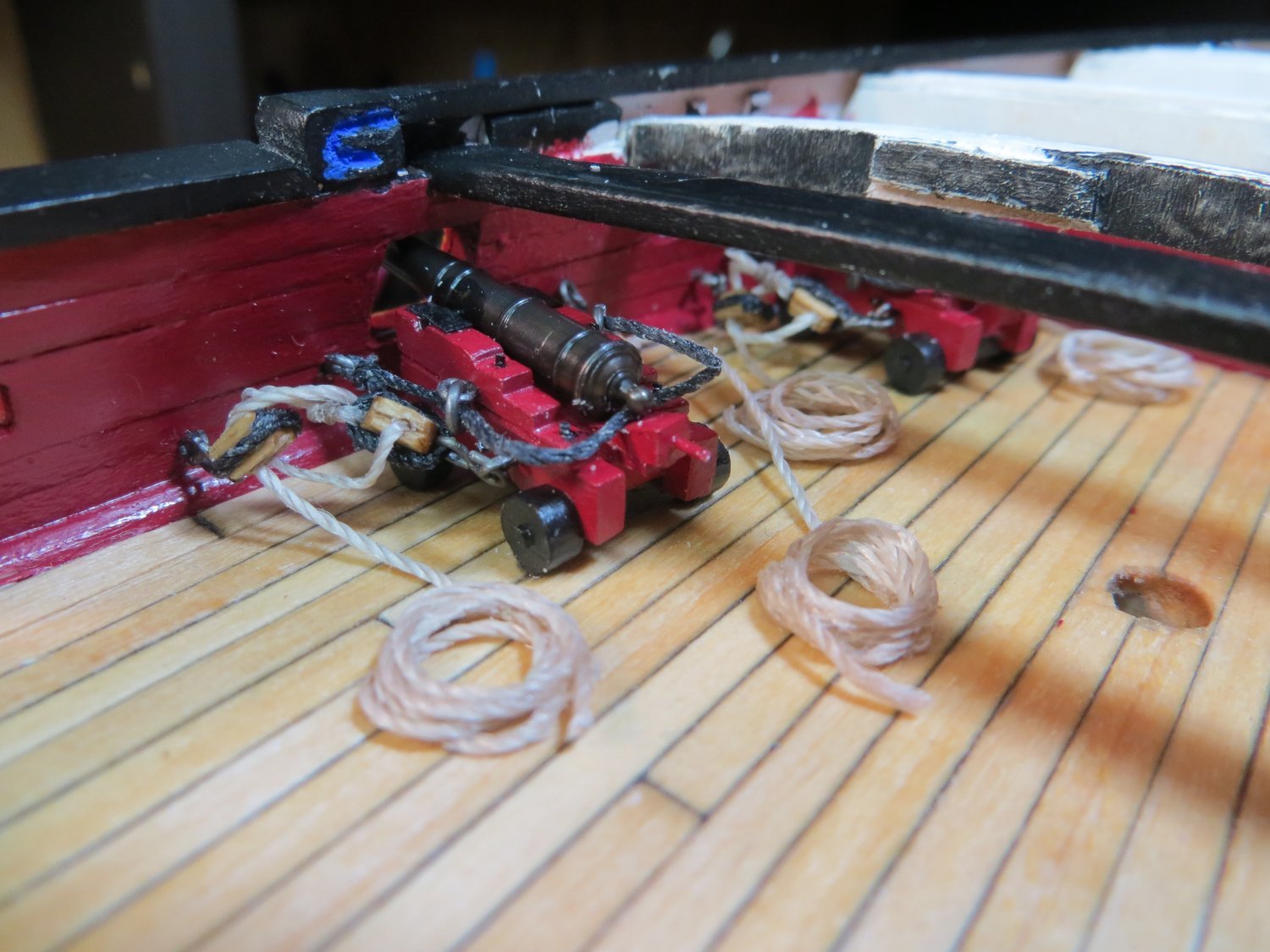
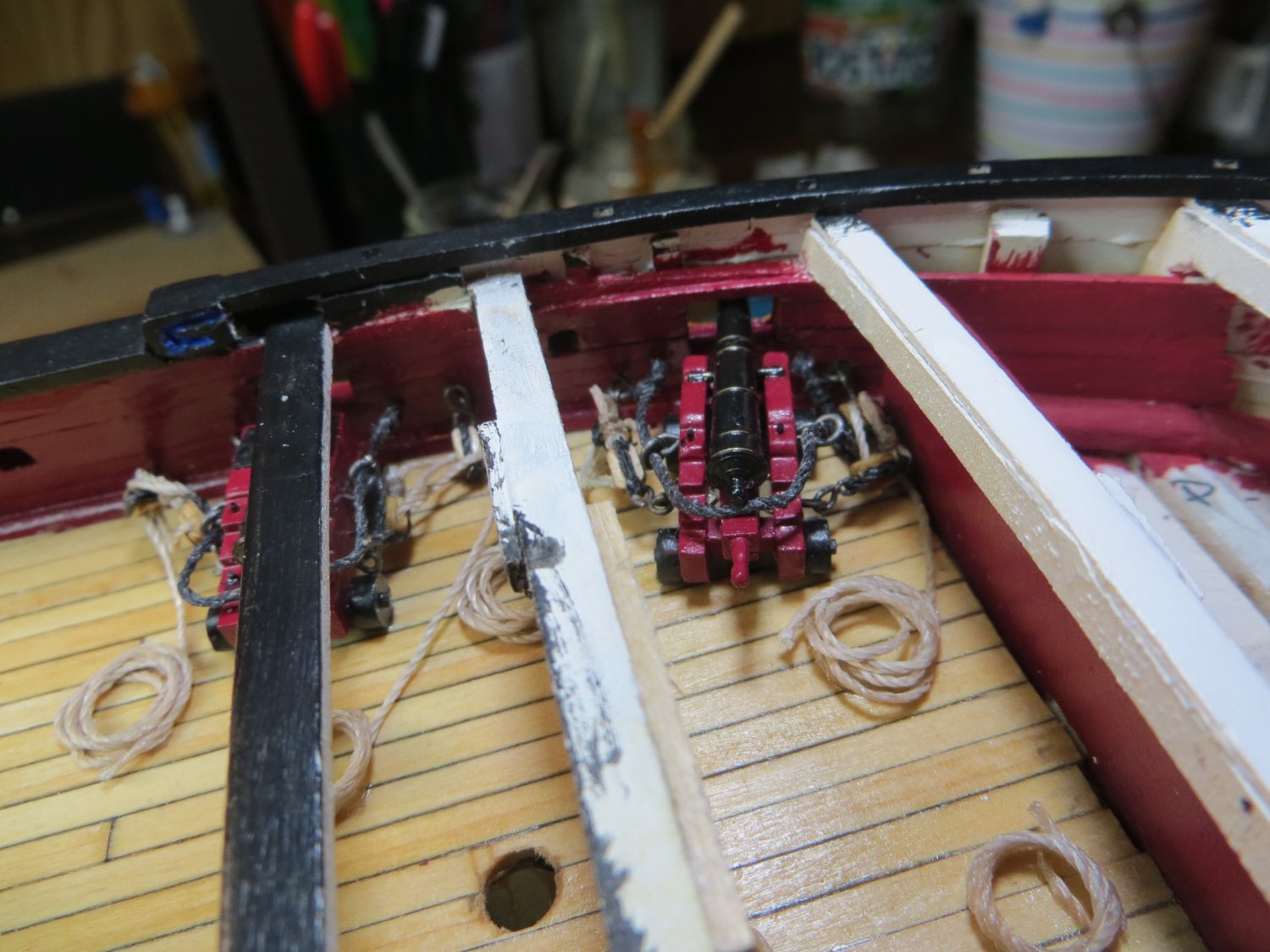
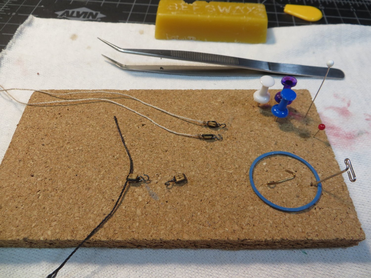
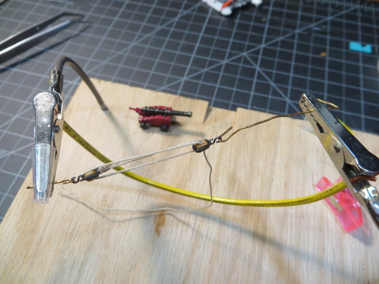
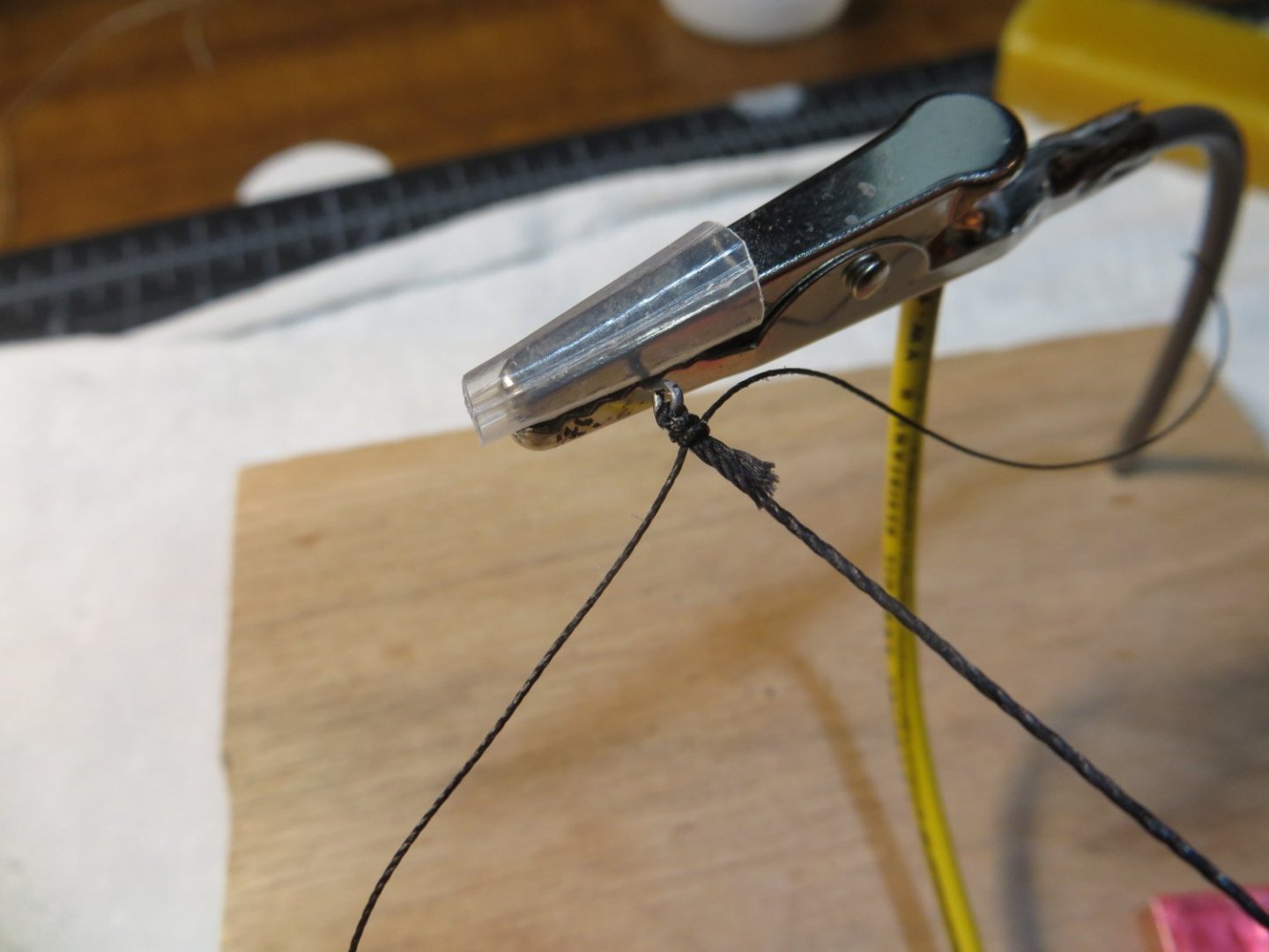
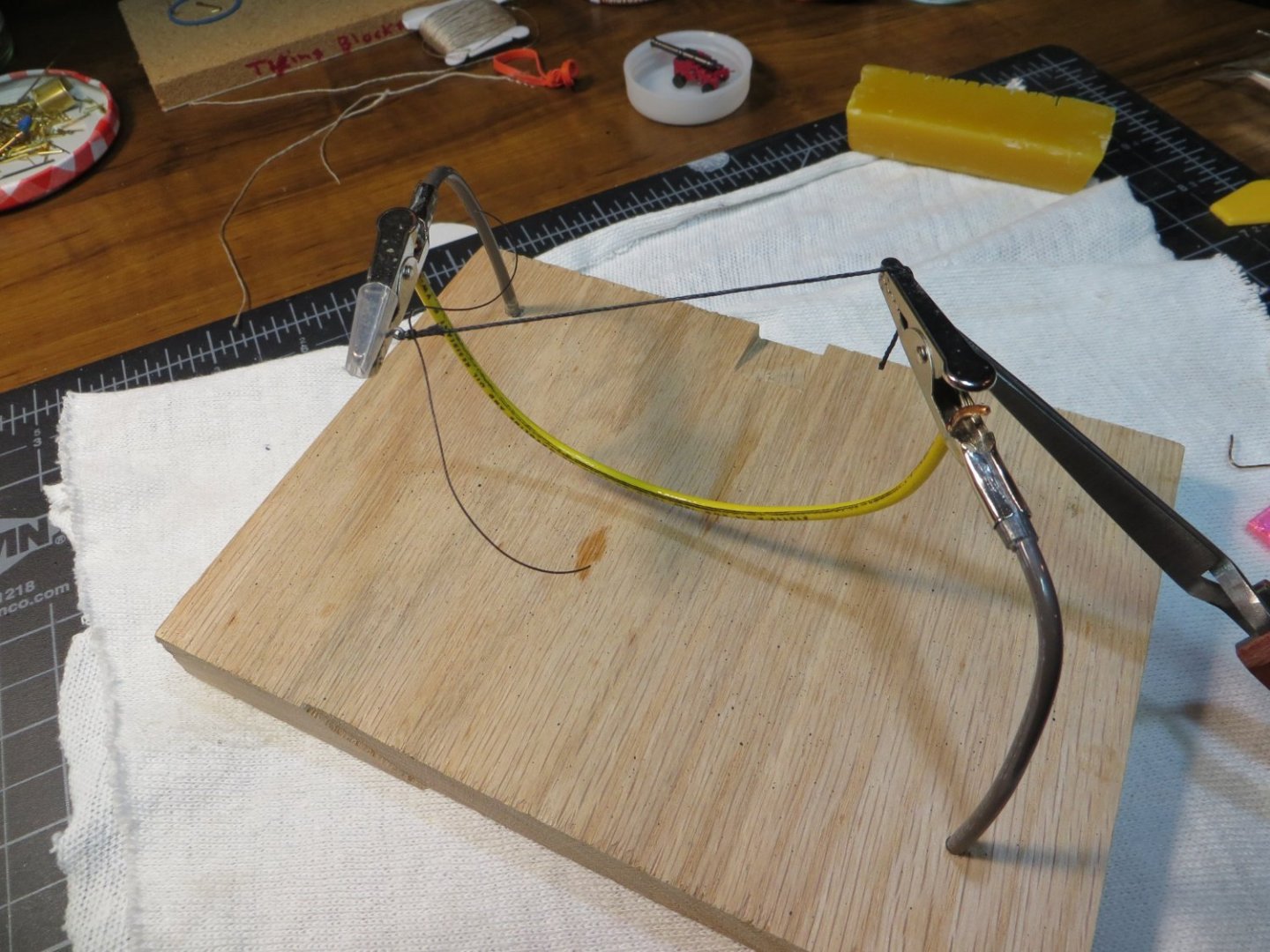
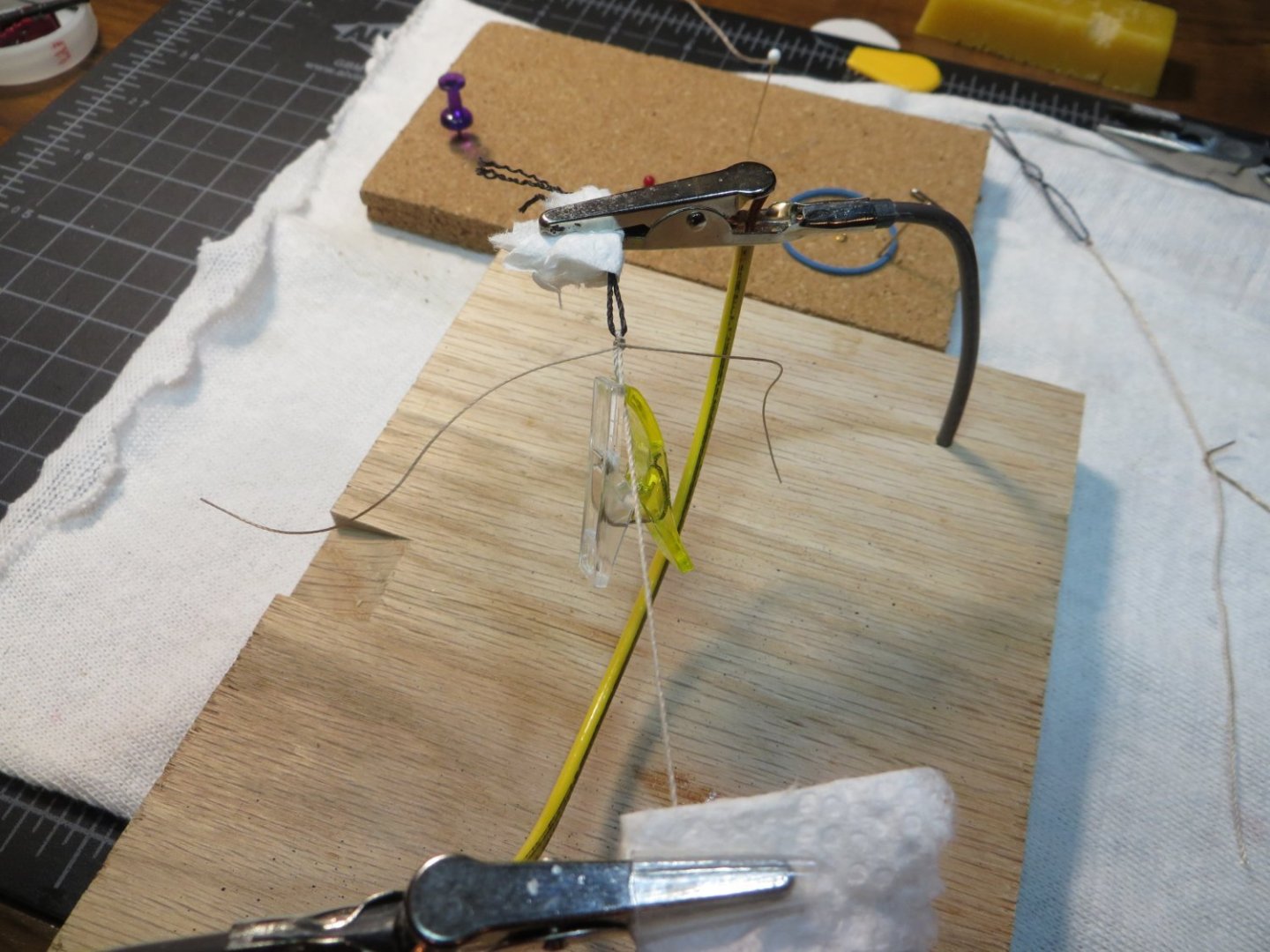
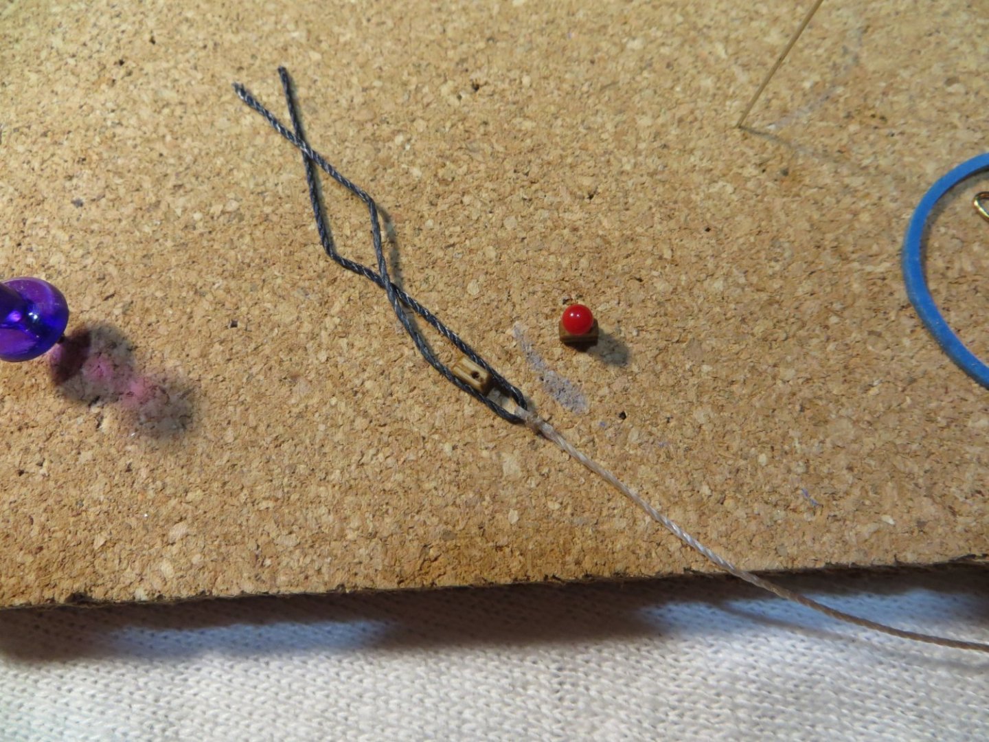
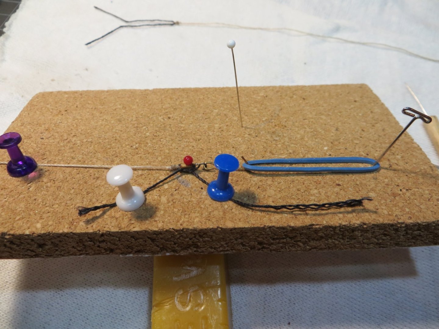
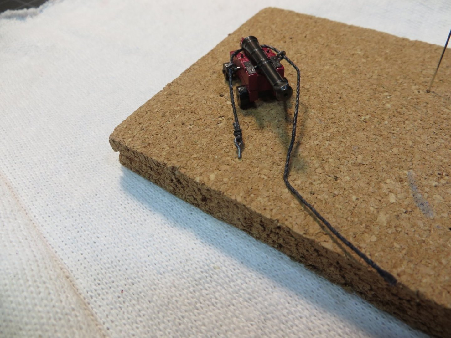
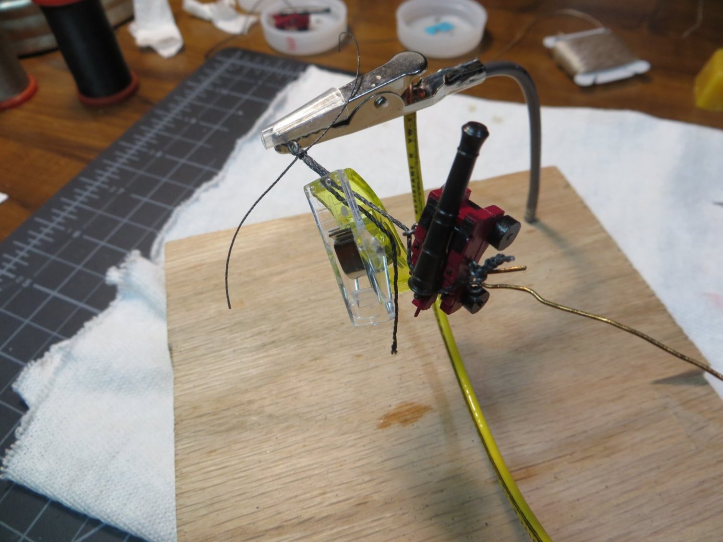
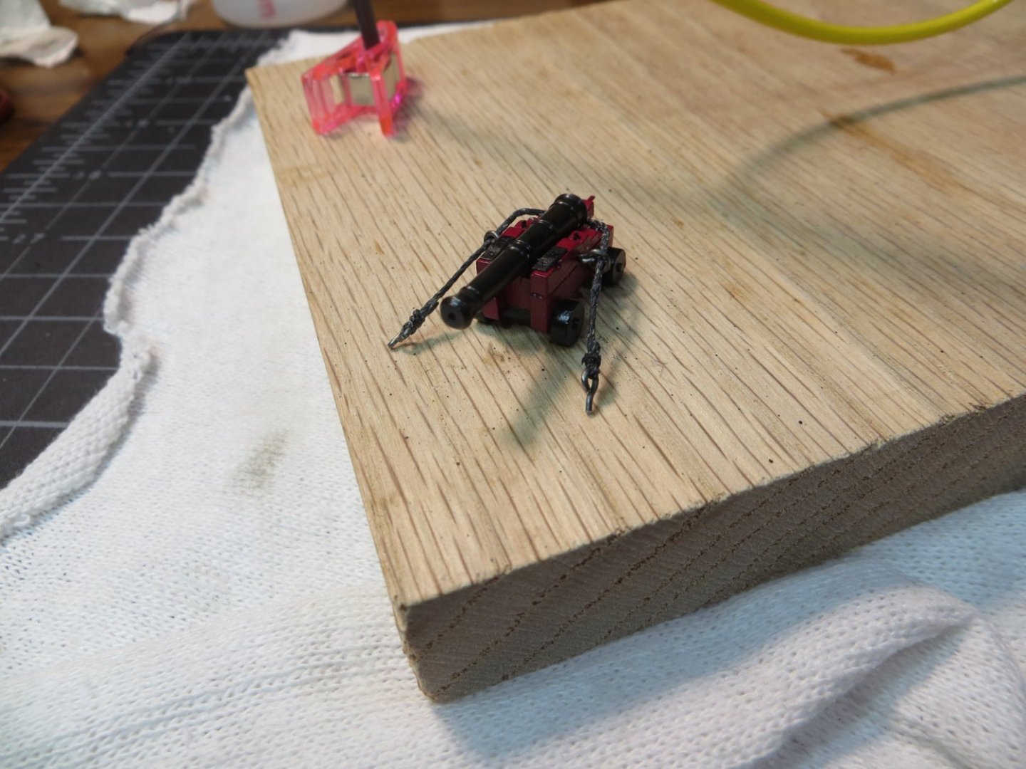
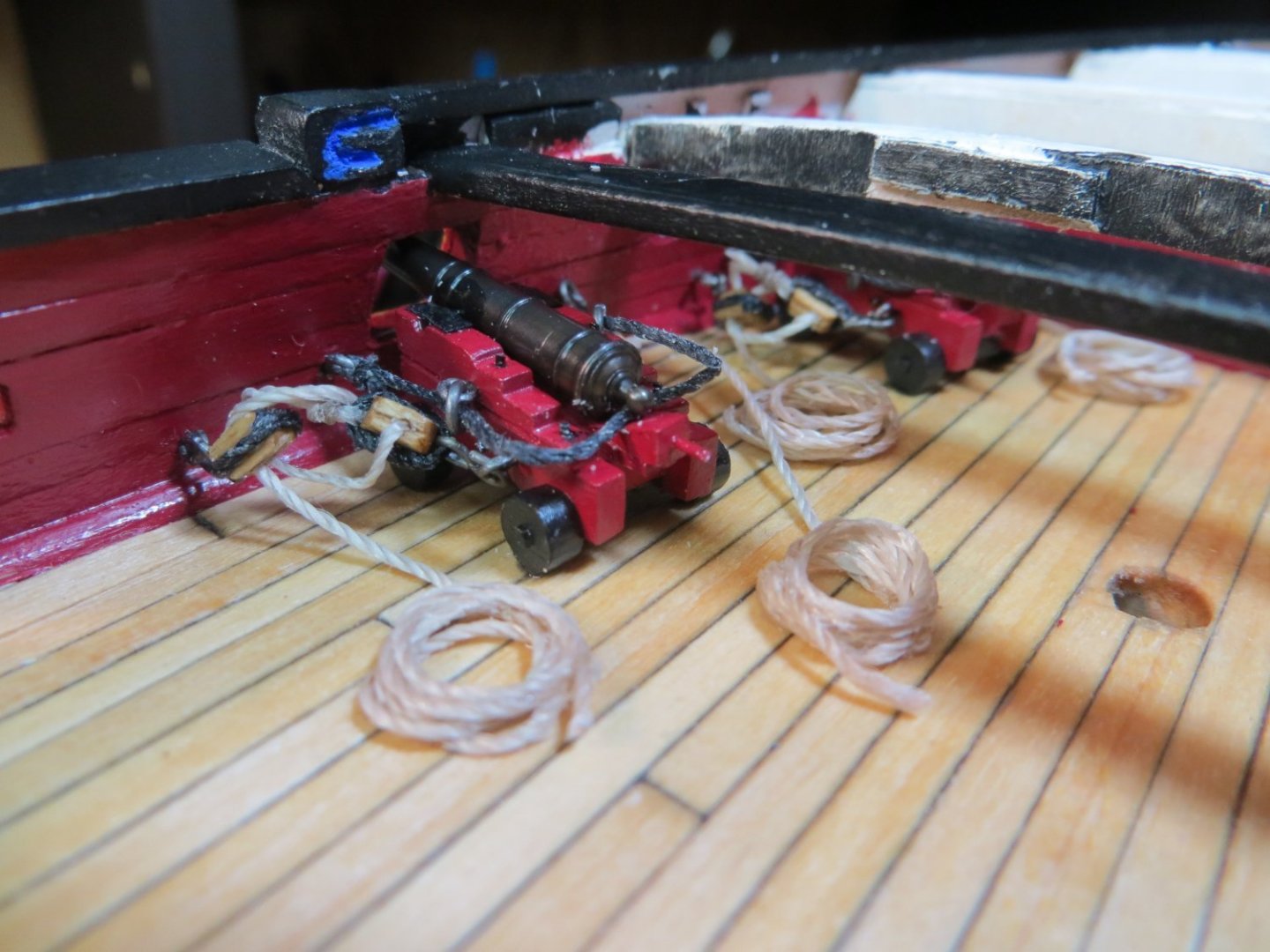
Rigging and Installing the Cannons on the Gundeck The next step is to add the rigging lines and install the cannons on the deck. There are 3 types of rigging lines on each cannon. (a) The Breech line limits the recoil of the cannon after firing (b) The Outhaul tackles are used to pull the cannon barrel into the gunport for firing (c) The Inhaul tackle is used to pull the cannon away from the gunport for loading. I decided I was only going to install the breech lines and outhaul tackles on my model. The inhaul tackles seem to clutter the deck in the models I’ve looked at that had them. Here are the steps that I used. Rigging the Breech Line – the breech line only requires an eyebolt to be seized to each end of the line. I dry fit the first cannon in the gunport to determine the proper length of line needed. I used the thicker 0.028” line. I used black line because I feel like the Breech serves more like standing rigging than running rigging. The eyebolt was seized with black thread off the cannon. Before seizing the eyebolt on the other side, it has to be threaded through the ring on the carriage, around the back of the cannon and through the ring on the opposite side. I used my homemade Helping Hands jig for seizing. I let the cannon hang in the jig while seizing the second eyebolt. Seizing the first eyebolt in the helping hands jig Breech line with 1 eyebolt threaded around the cannon carriage Seizing the 2nd eyebolt with cannon in the jig! Breech line completed Rigging the Outhaul Tackles – this rig is more complex. I used a 1/8” single sheave and double sheave block with tan 0.021” rope. The single block requires an S-hook to be stropped on one end. The seized loop of the tackle rope is stropped to the other end of the single block. The double block only needs an S-hook stropped to one end. These pieces are hooked onto the helping hands for threading the line in the blocks. Seizing the black “stropping” line to the tan tackle rigging line Single block and strop line with rigging ready for assembly on my cork block tying jig Everything tied down on the jig. A couple of drops of CA glue are used to hold the knot and secure it to the block. Completed rigging ready for threading the lines Threading the lines through the blocks using the helping hands jig All lines attached to the cannon carriage and ready to install on the deck Installing the Cannons on the Gundeck – this is without a doubt the hardest part of this entire process! The space is really tight and made tighter by having to work around the focsl deck supports! I used a fine punch to make pilot holes where the eyebolts need to be positioned on the gunwale. I used the pin vise to make the holes. Be careful you don’t go through the outer hull! I attached the eyebolts for the tackles with some thick type CA on the end to hold them in place. I found the best method was to attach the forward side rigging first. First the breech line, then connect the S-hook for the tackle to its eyebolt. Carefully squeeze the loop closed. Then I did the aft side. Once everything was set, I used CA glue on the rear trucks to hold it in place on the deck. I made rope coils separately. I tried several methods for making them. I had the best luck with simply wrapping the tan line around a smooth pen barrel. Then I used dilute PVA and rubbed it around on the line with my fingers (what a mess!). I let it partially dry then laid it under a magnet to flatten it out. I wanted these ropes to have the look of laying in loose coils. I glued the rope end coming off the tackles to the deck. The coil was laid on top of the rope end using the thick type CA. Here are a couple of pics of the finished product. I’m glad these will be hidden under the focsl deck! I got better with each cannon. I think the rest of the cannons will be easier with more open space to work with. I hope my notes are useful to you when you are installing your cannons. I still have 1 more cannon left to install. Then I will be ready to plank the focsl deck. Thanks, Ed


-
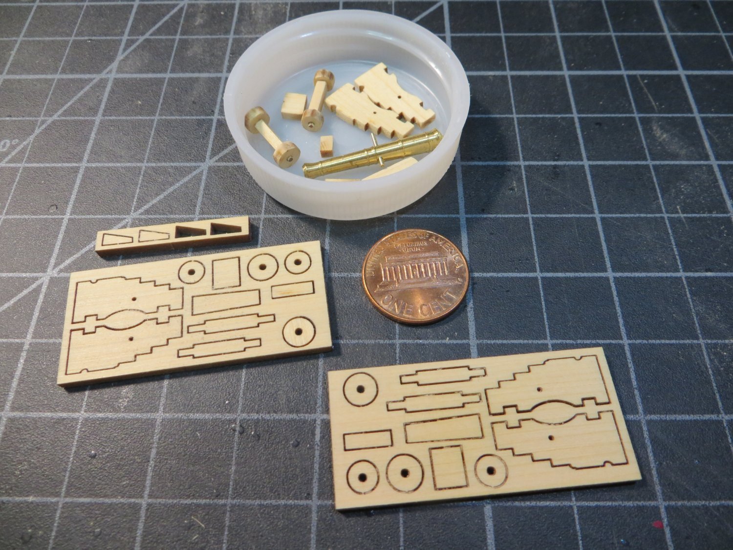
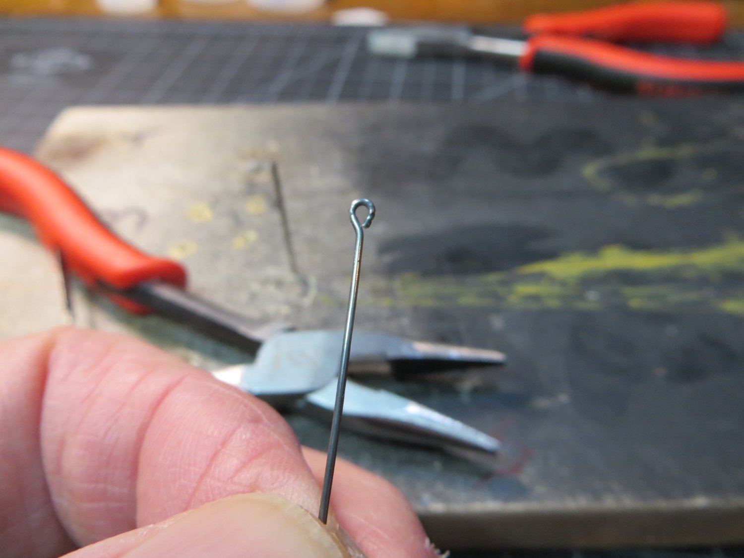
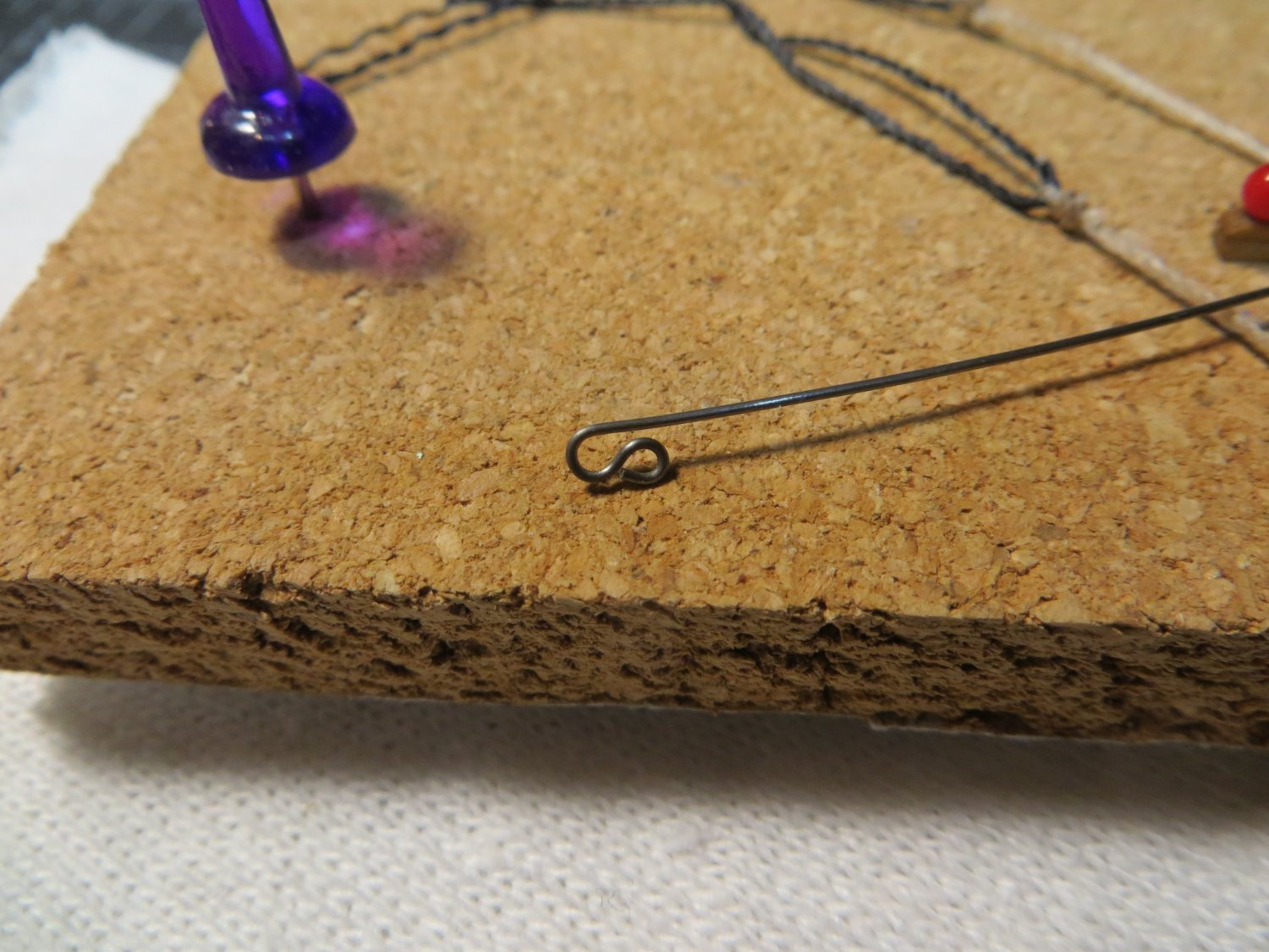
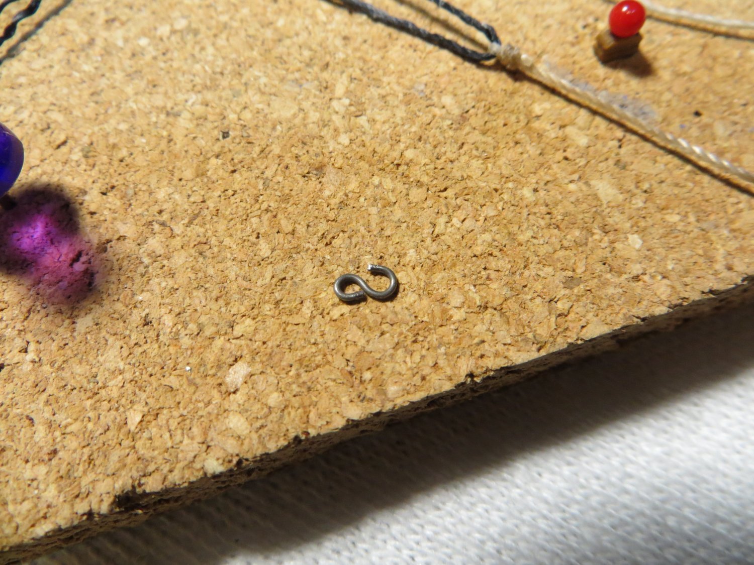
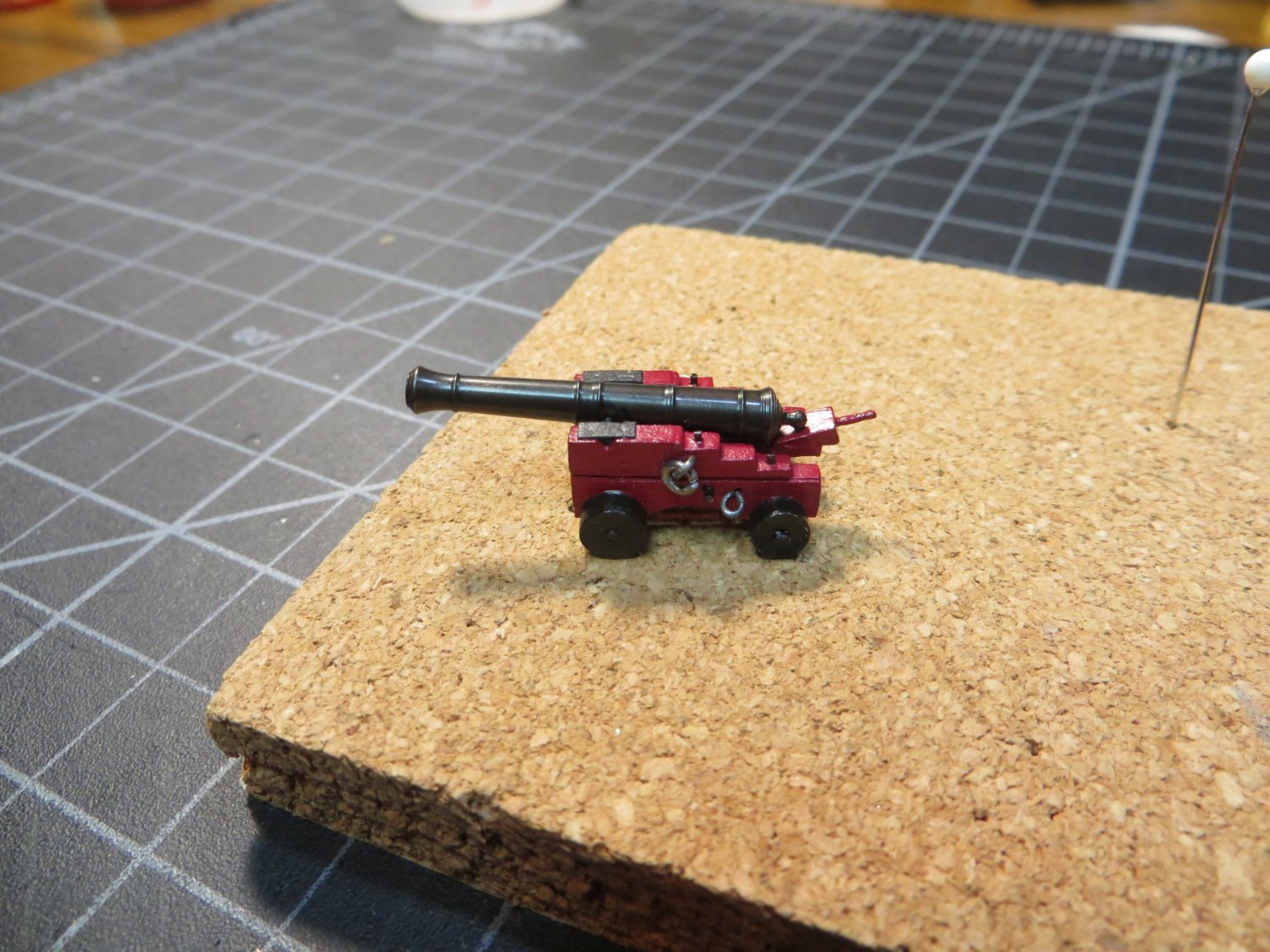
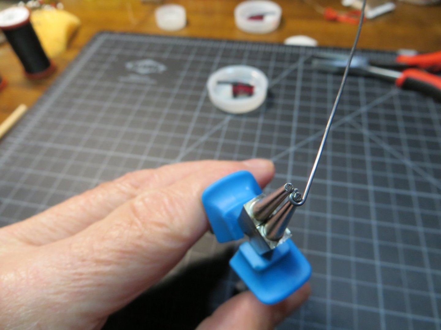
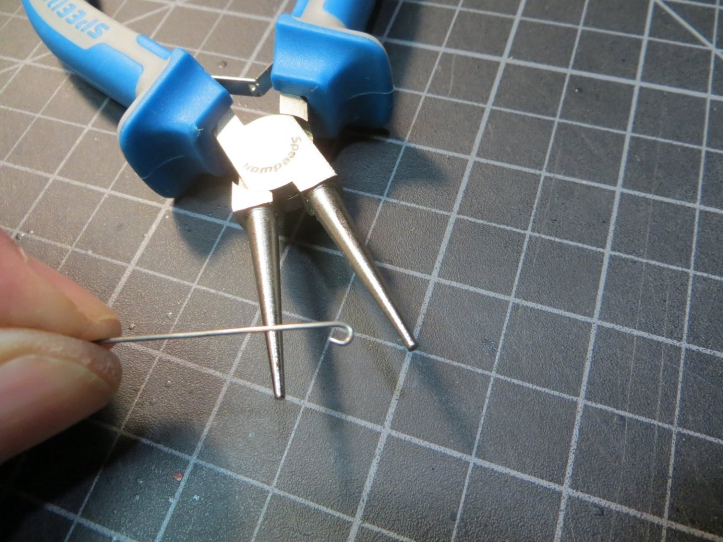
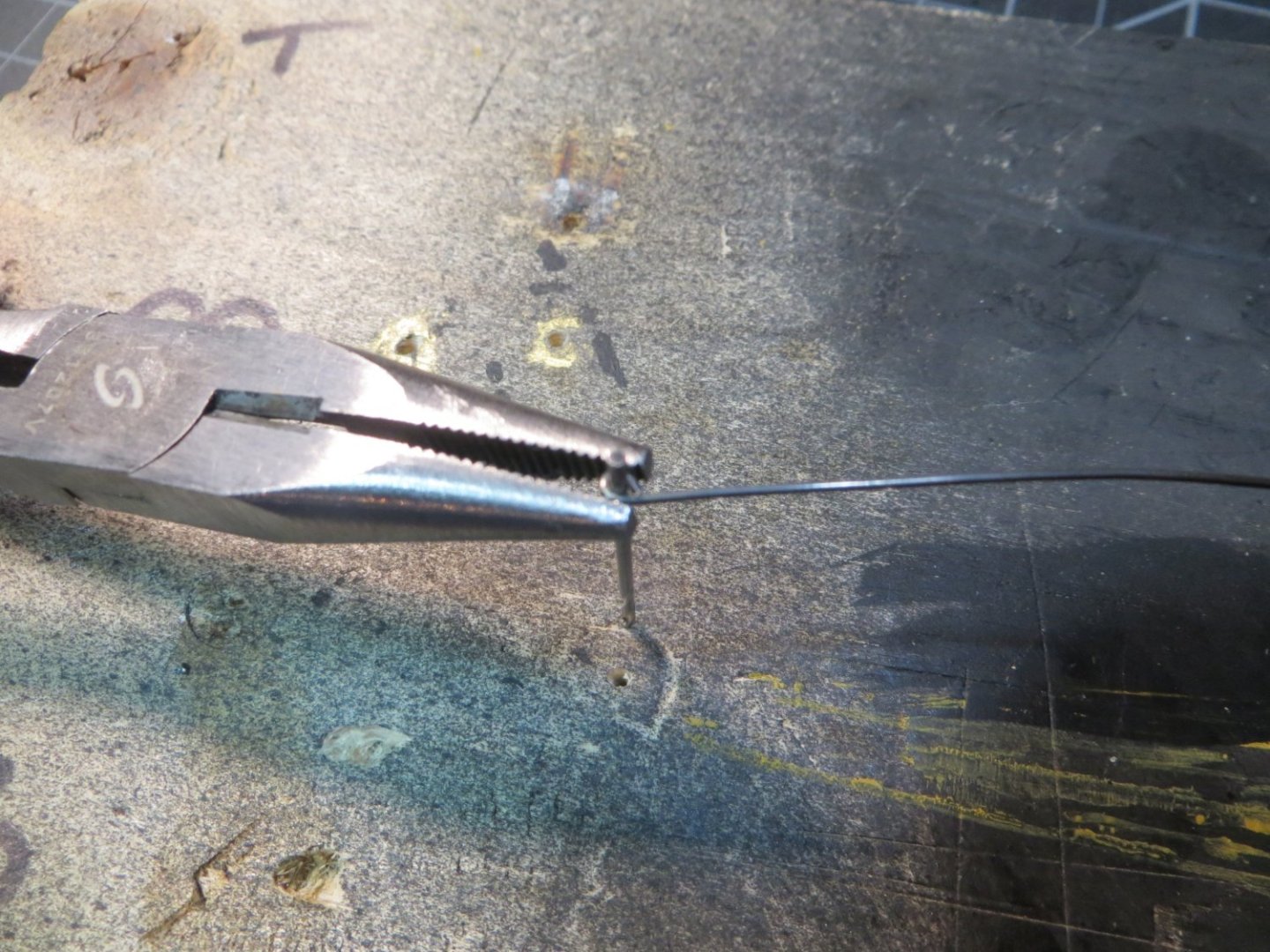
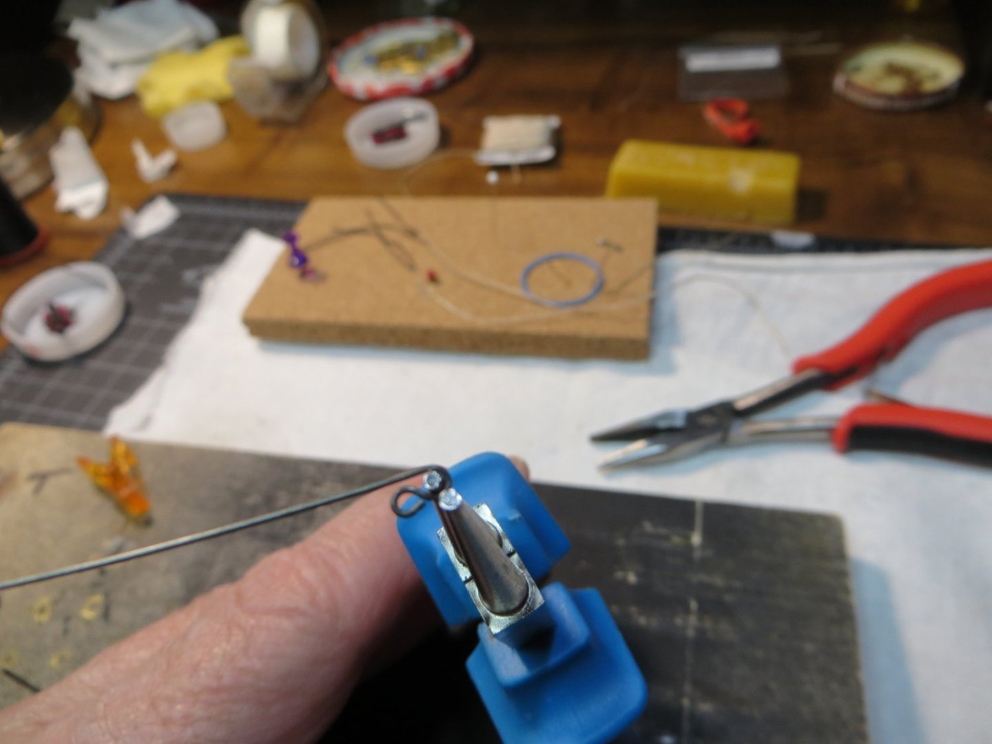
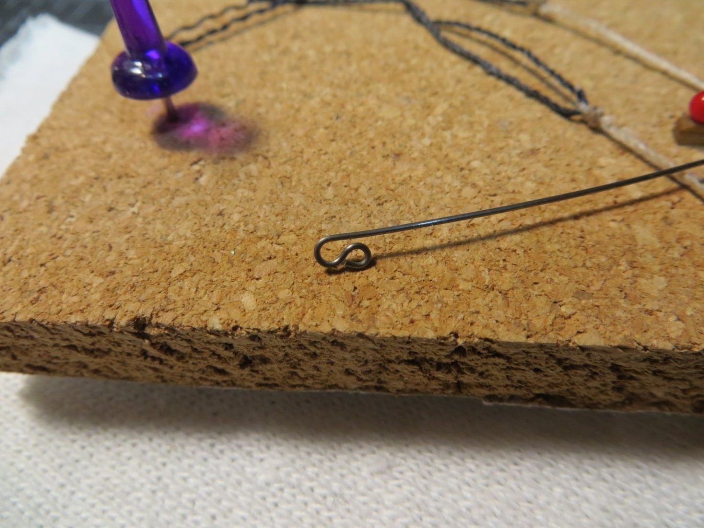
Make and Install 4 Cannons under the Focsl Deck Happy New Year to all my fellow Rattlesnake builders! I have one more deck to plank. But before planking the focsl deck, 4 cannons that are located under this deck need to be built and installed. I made one cannon, (seems like that was a long while ago!) to use for setting the height of the gunports. So, I need to build 3 more from the kits that I purchased from Syren Ship Model Co. There is a lot of work involved in building these little things! This is taking many hours to complete! Chuck Passaro provides very good instructions, so I’m not going to cover that here. In spite of my best effort to set the gunport height accurately, I still ended up with the cannons being a bit too tall. This is an issue other’s have mentioned with the Syren cannons on the Model Shipways Rattlesnake. To compensate for this issue, I did the following: a. Using mini-files I deepened the groove that holds the pins of the cannon barrels b. Deepened the slots that the front and rear axles fit into c. I also used a 1/32” x 3/32” piece of stripwood for the carriage bed board to lower the barrel I decided to try using “Brass Black Metal Finish” to treat the brass cannon barrels. Other’s have mentioned this on their build logs. I really like the way the blackened cannons turned out. I also bought the “Dark Annealed” steel wire for the metal fittings on the carriages. I intend to use this type of wire throughout the build. It seems to be a better fit for this older ship. Brass wire & fittings were used on my Bluenose build. Bluenose 1 was a “newer” ship circa the 1920’s. Here are before and after pictures of the cannon (pre-rigging) There are lots of eyebolts, S-hooks and rings required for rigging each cannon. I’ve developed a pretty good method for making this hardware. I made a post on this topic in my Bluenose log. But I thought I’d update that post here with the Rattlesnake. Method for Making Eyebolts and S-Hooks 1. Use a pair of round-nose pliers to bend the wire about ¾ of the way around the nose 2. My pliers are 1/16” at the tip. I wanted smaller eyebolts so I have a 3/64” drill bit inserted into a build-board. Place the wire loop over the bit. Squeeze with needle-nose pliers to tighten the hole around the bit 3. Use the same pliers to grasp the shaft and bend the wire to square up the end under the loop. Snip off the long end for your eyebolt! 4. If you need an S-hook, put the uncut shaft back into the round-nose and make another loop going the opposite direction 5. Snip off the end, so it’s even with the bottom of the first loop. After I attach the open end to the rig, I gently close the loop tight with pliers. In my next post I will show how I’m rigging the cannons and setting them up on the gun deck. Best regards, Ed


-
I finished planking the Quarter deck, so thought I would give you all an update. This deck actually took me longer to complete then the main gundeck. There were more details like the coamings and ladderway that added time that I did not have on the gundeck. The planking got pretty hairy when I got close to the gunwales. Since the sides angle inboard there's not a lot of room to work. Especially at the narrow part of the stern. Don't ask me how this happened, but the deck on the port side ended up about 1.5 millimeters wider than the starboard side. I had to insert a short nibbed plank on starboard side behind the beam. It's pretty well hidden under the railing. One more plank filled the space on the port. But, a small tapered sliver was needed right above the beam. You can see these diffeences in the first picture. Maybe I was off on the center line? I really tried hard to get that right! Oh well, Only you guys & I will know!! I decided to stain that beam in front of bulkhead I with the darker Golden Oak. I need to add another coat to darken it up a little more. The rest of the deck was stained with Minwax Natural, same as the gundeck. The next step is to build the 4 cannons that need to go under the Focsl Deck . These need to be put in place before I can install this deck. Here are some pics of the completed quarter deck. Thanks, Ed


-
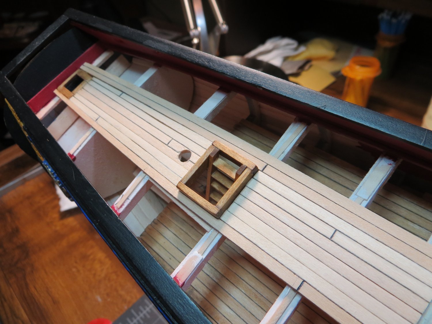
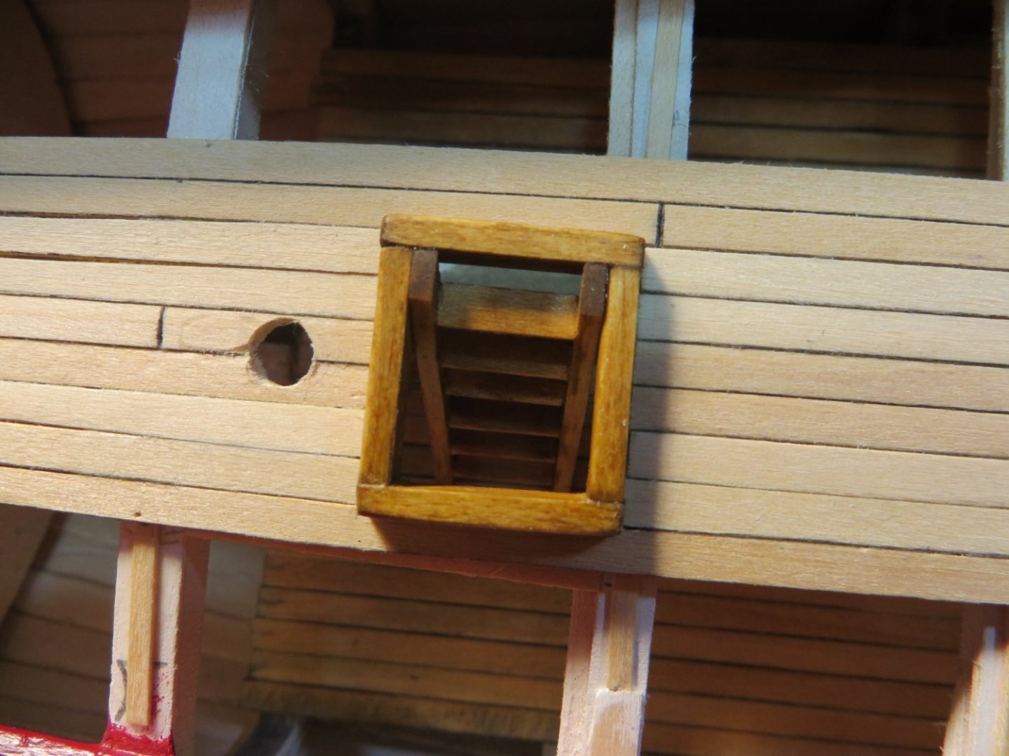
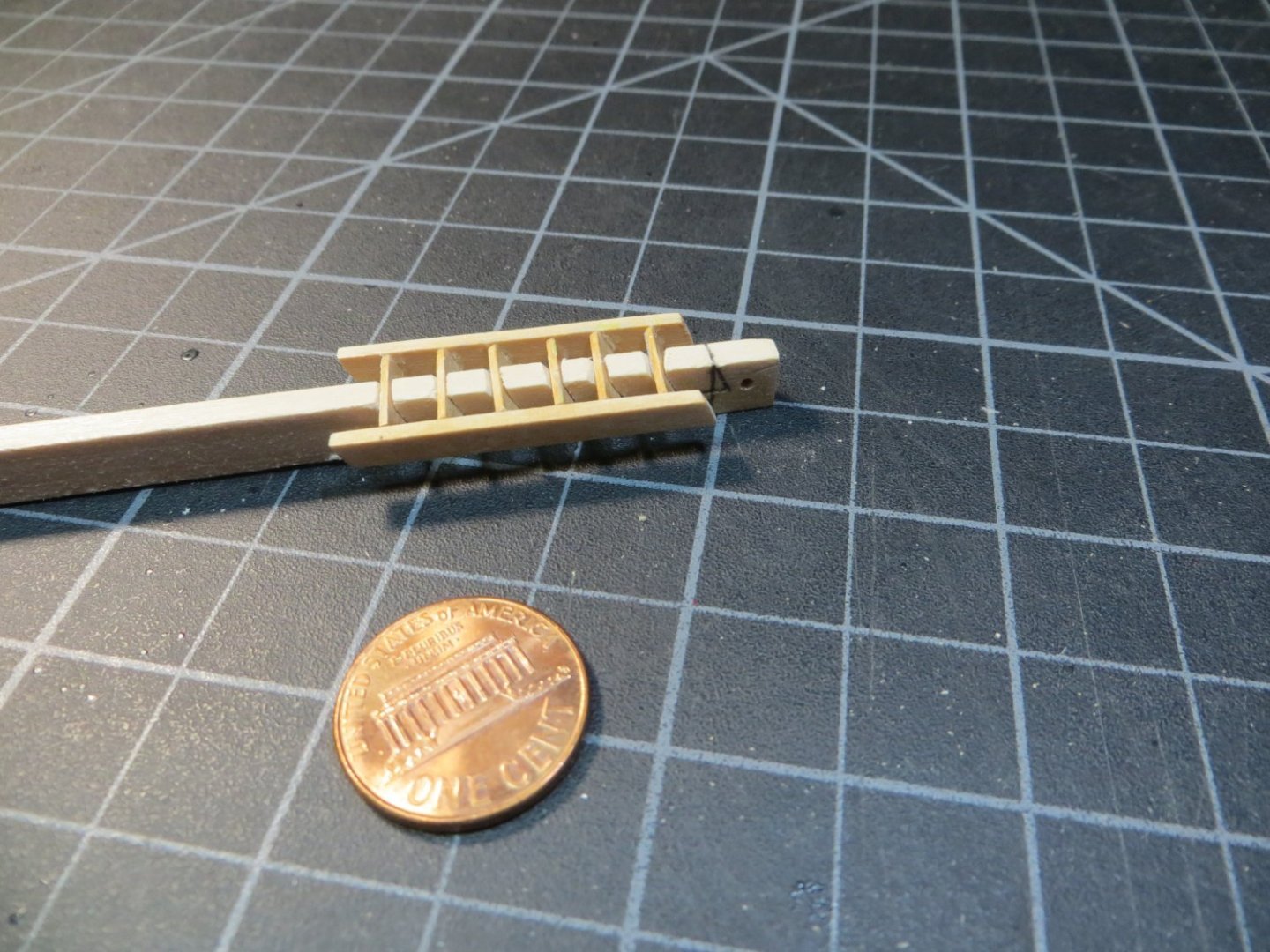
Finally got around to installing the ladder on the quarter deck today. It came right off of the little jig very nicely. Allowing the glue to set for several days seems to have helped. It feels pretty sturdy. After some light sanding, I applied 2 coats of Minwax Golden Oak stain to match the coamings. The ladder was then glued to the coaming. Here is the end result. I think it looks pretty cool! Hope you do too. Ed

-
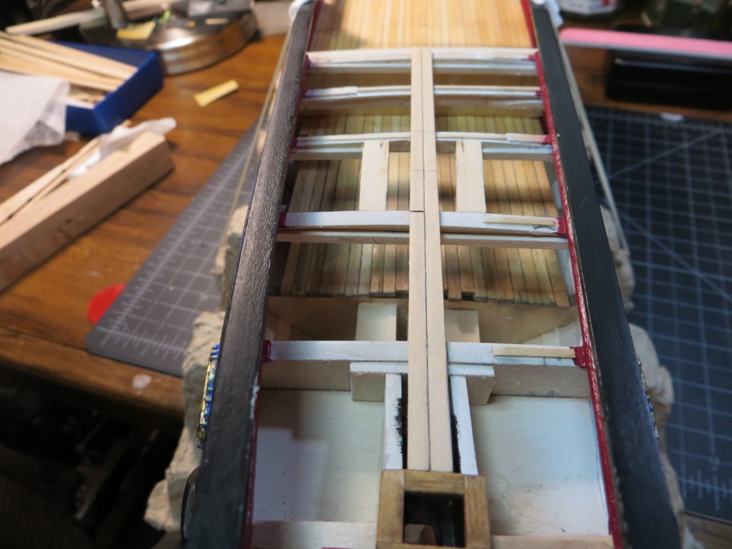
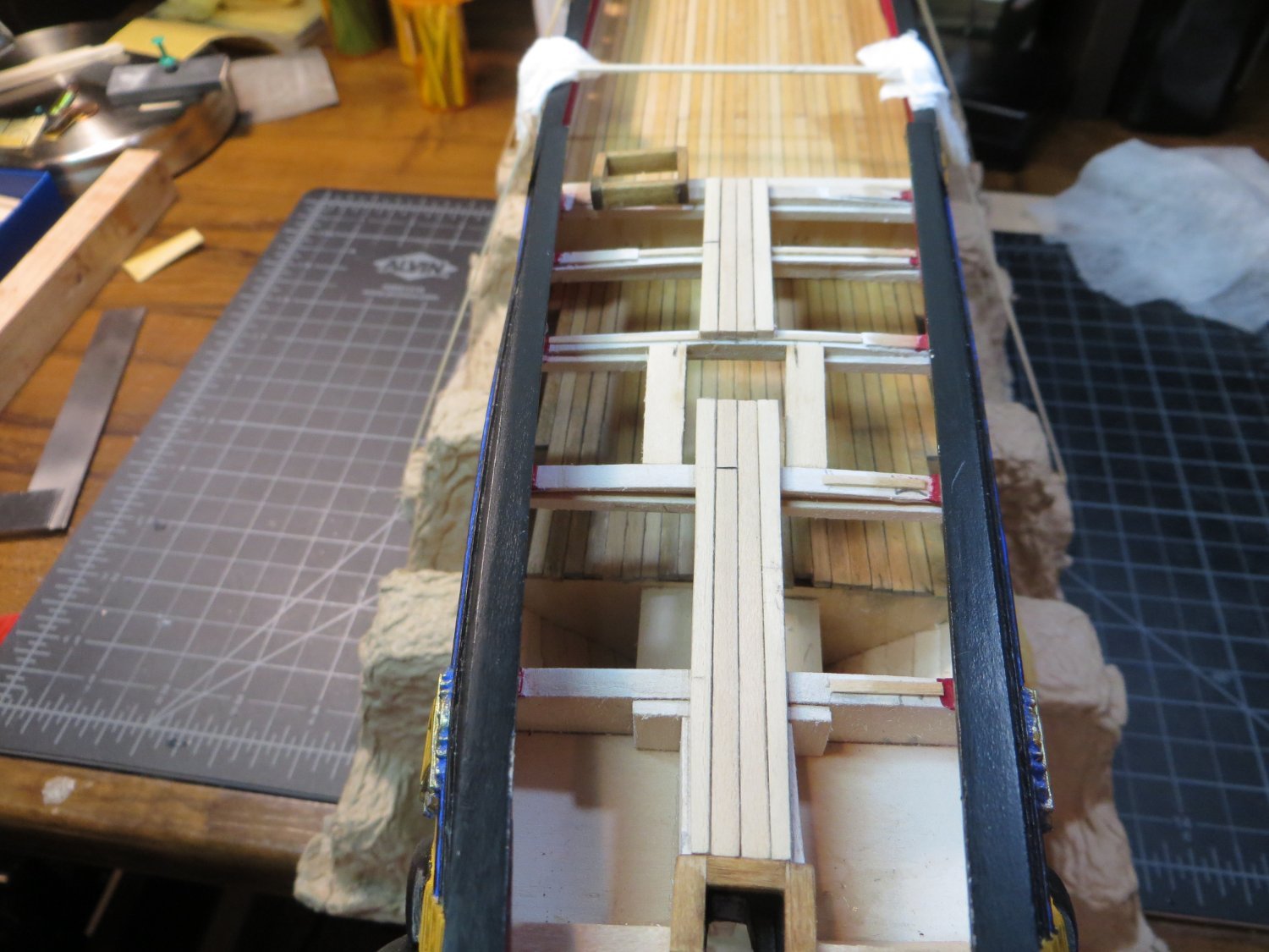
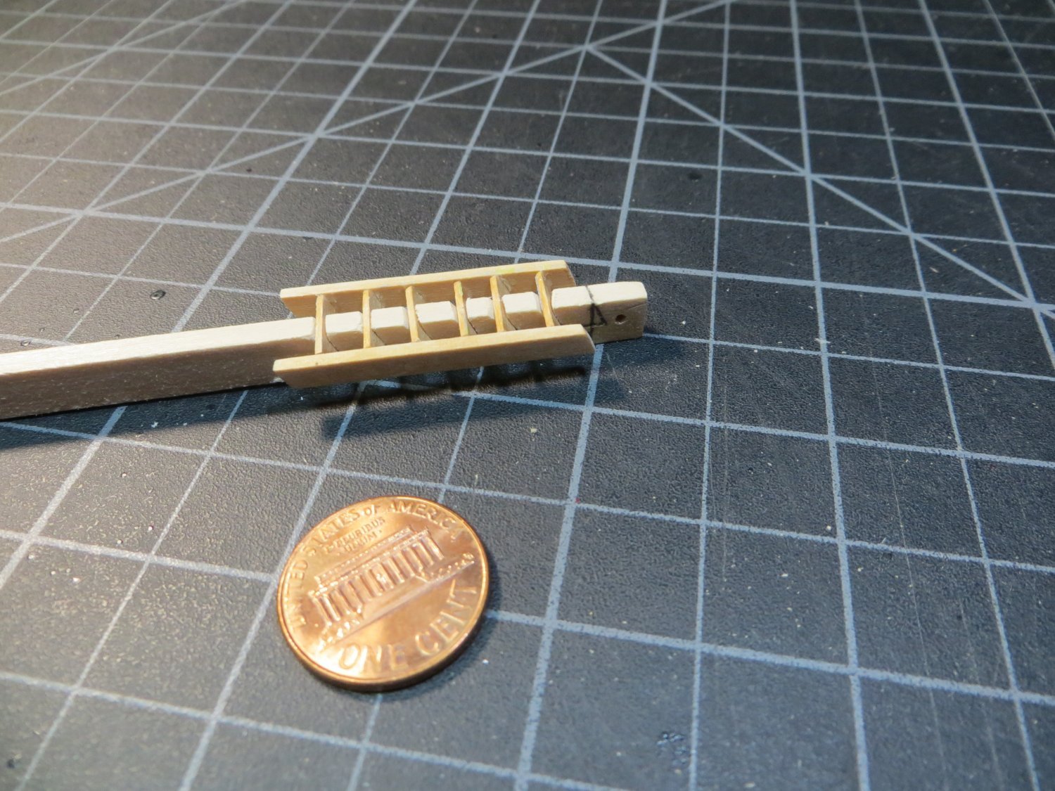
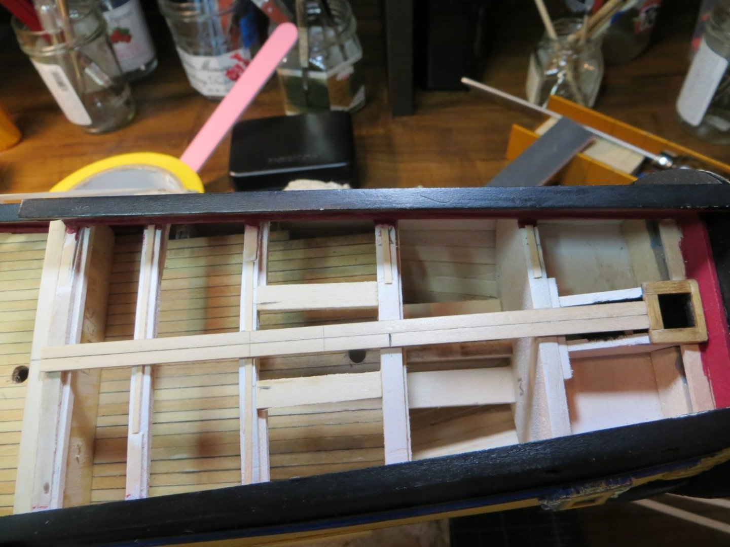
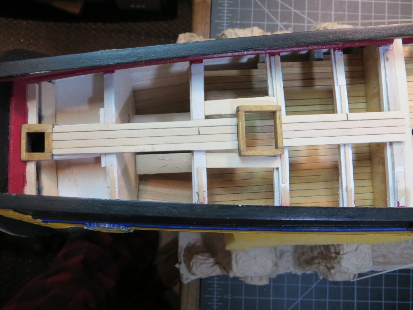
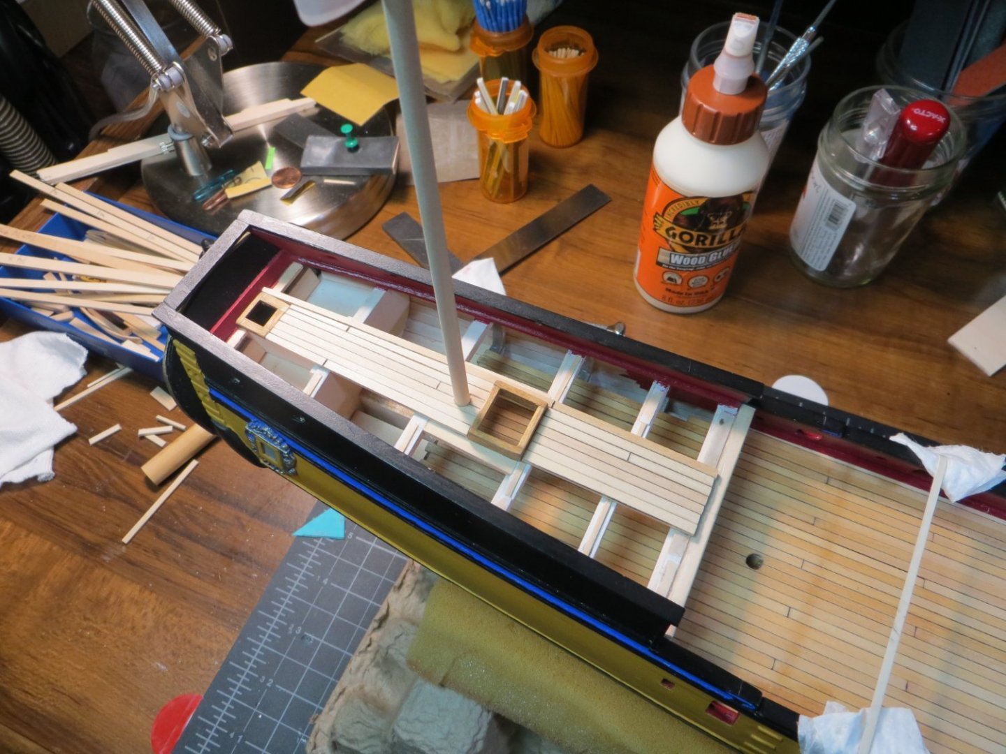
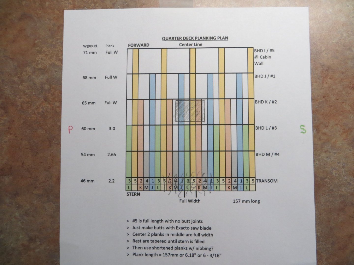
Step 37: Plank Quarter Deck I still have some work to do before I’m done planking the quarter deck, but I thought I would provide an update to cover some progress on a few steps that accompany the actual planking. Also, I took a couple of weeks off from the shipyard. My wife and I took a nice vacation in the Caribbean to celebrate our 45th anniversary. Now, it’s back to deck planking. · The first thing I had to do was make a new butt stagger plan for the Q-deck. These planks need to taper at the stern, but are full width at bulkhead I. A lot of the butt joints are hidden. I faked them with an Exacto saw cut and a graphite pencil. Here is a pic of my planking plan. · There is very little help from the plans and/or build logs on how to handle the inboard stern bulwark. There doesn’t appear to be anything to support the deck planks on the inboard side of the transom. I decided to add a ledge to support the deck planks where they butt up to the front of the transom. I also added supports for the coaming where the rudder post makes a hole in the deck. · While I was at it, I also added supports between BHDs K & L for the ladderway coaming. Be careful not to block the location of the mizzen mast. It’s pretty close to the ladderway. · Made the coaming for the ladderway as follows: o Per plan coaming is 20 x 18 mm. Use 3/32 x 3/16” stripwood, PN3628 o Stained the coamings with Golden Oak to set them apart from the deck o Glue the rudder post coaming in place at the transom, after staining. Need this before planking · Next, I set the 2 center deck planks to be sure they are centered and square. I decided to glue these as full-size planks, so there is a square base to build the tapered planks from. Once the glue dried, cut out the space for the coaming. After cutting out the space for the ladderway coaming · I did not glue the ladder coaming in place yet. Continued to build the deck around it o I used my mini-plane to do the tapering of the planks (one of the best purchases I have made!) · After I covered the width of the ladder coaming, I decided I better make the hole for the mizzen mast. The wisest thing I did was to start with a smaller hole then required and use the smallest dowel to check the angle of the mast the 2 holes provided. This gave me room to make adjustments. I made a template using the NMM plans that Gregory provided to get the angle between the quarter deck and the mast. I’m very satisfied with the results. Thanks Gregory! · Also, before continuing with planking, I decided to build and install the ladder for the quarter deck. I tried to do it without the jig that is recommended in the plans. I thought if I could make a rabbet cut on the inside of the stiles, I could build a sturdy ladder. This didn’t go well. So, I made my own version of the jig. I’m still worried about it falling apart when I try to remove it from the jig! I’m going to let the glue dry until after Thanksgiving. I’ll provide more pictures after I install the ladder. I hope everyone has a great Thanksgiving Day with family! Best regards, Ed


-
Thanks Gregory! Good tip about using a template. I'm still struggling a little bit with how to line up the holes. I made the hole in the main deck after I completed planking it. Now I need to drill the hole in the quarter deck so that it provides the correct position and angle. I guess I will start with a small hole, in what I consider to be the proper position, and adjust it using a very thin dowel through both holes?
-
I have a question for any of the multi-deck ship builders. How do you line up the hole for the mizzen mast on the quarter deck with the hole below on the main deck? Should the masts be angled slightly to aft? I'm planking the quarter deck and before I go too far, I want to make sure I get the hole positioned for the mizzen. Thanks, Ed
-
Hi Ken, May I ask what you used to paint or stain your coamings & grates? And how about the bitts & ladders? Is that brown enamel? If I haven't told you already, your Rattlesnake is outstanding! Very beautifully done! Thanks, Ed
- 152 replies
-
- 1
-

-
- rattlesnake
- Model Shipways
- (and 1 more)
-
Hi Gregg! Thanks for looking in and also for your kind words. Awesome that you have been able to find some useful information from my Bluenose build log. I enjoy sharing more of the "how I made this" details. I really like when I find good tips for the step I'm working on at the time! I see from your project list that you are into schooners. I really liked building my Bluenose. I wanted to build a square-rigged ship that had some cannons for my second build. Rattlesnake is certainly fitting the bill! I was checking out your Bluenose build. Looks like you've got a really nice build going with your model! Keep up the good work! Ed
-
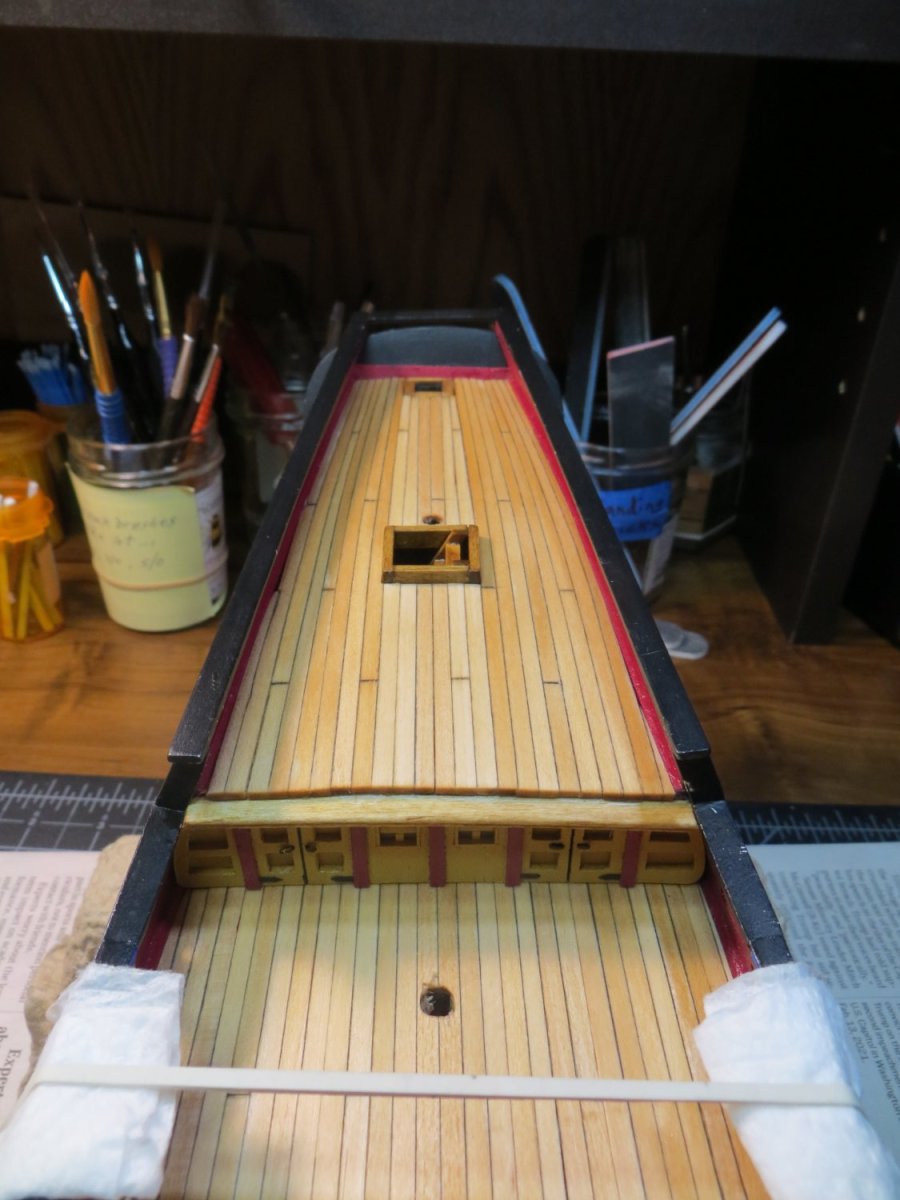
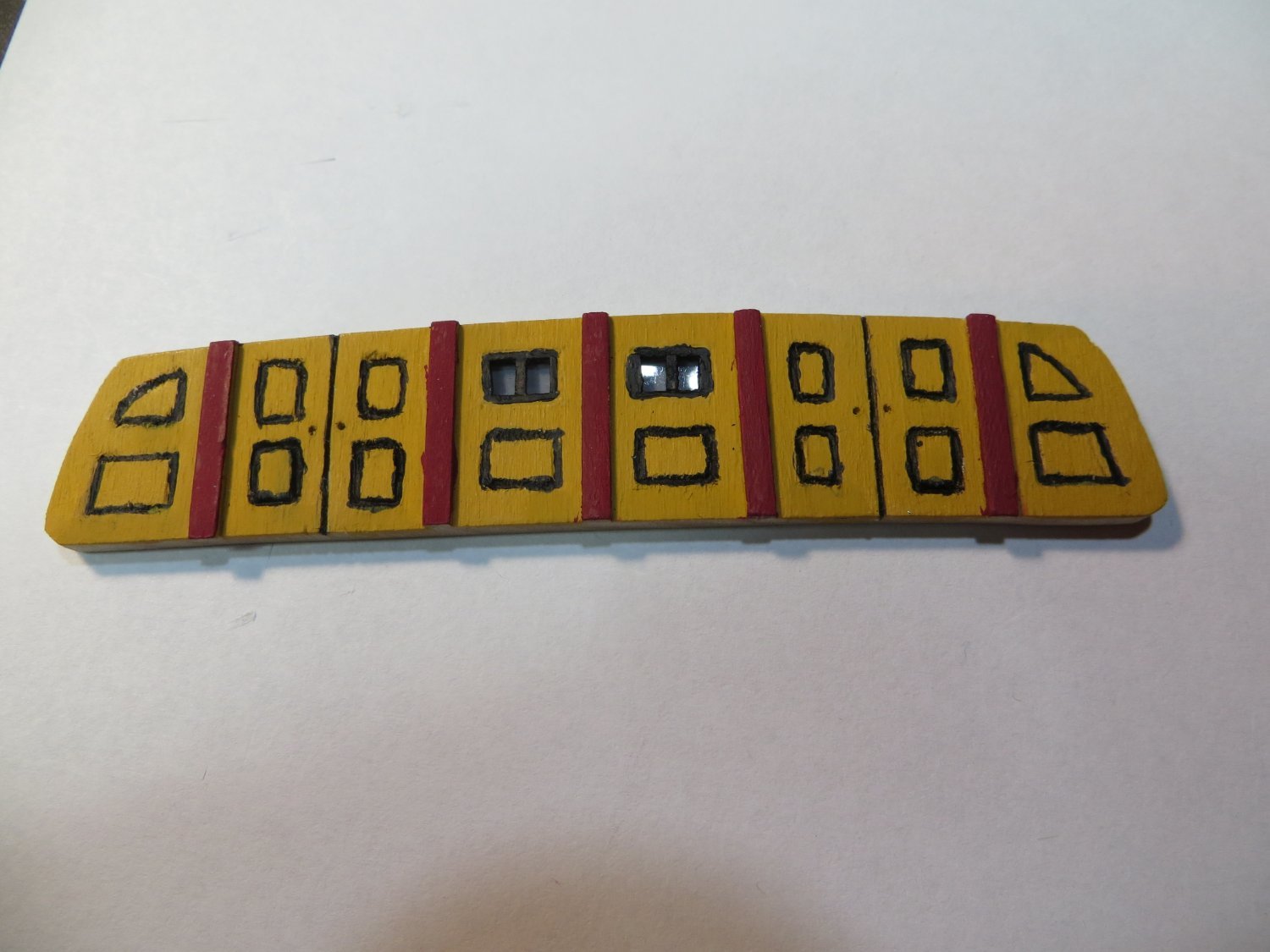
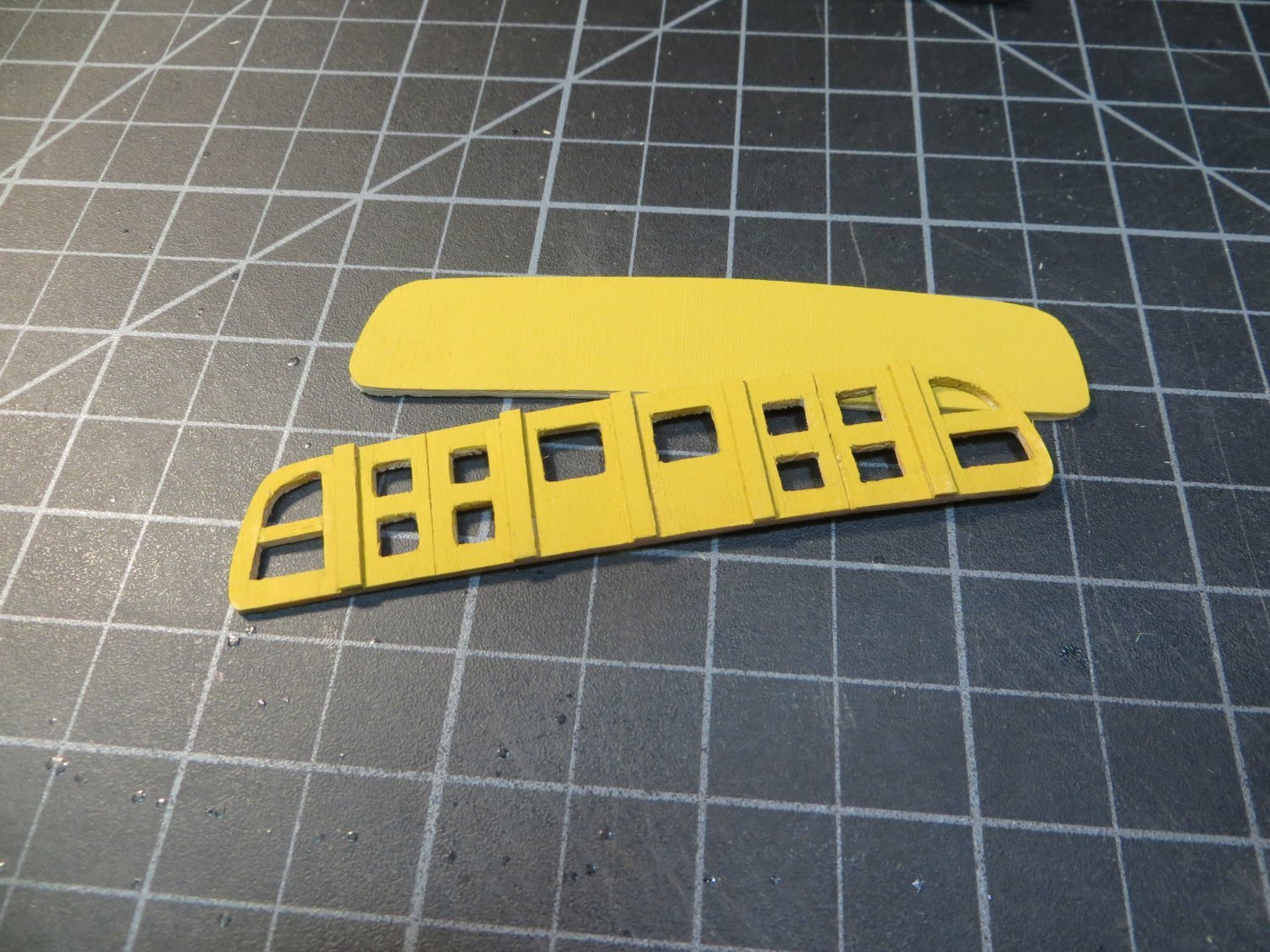
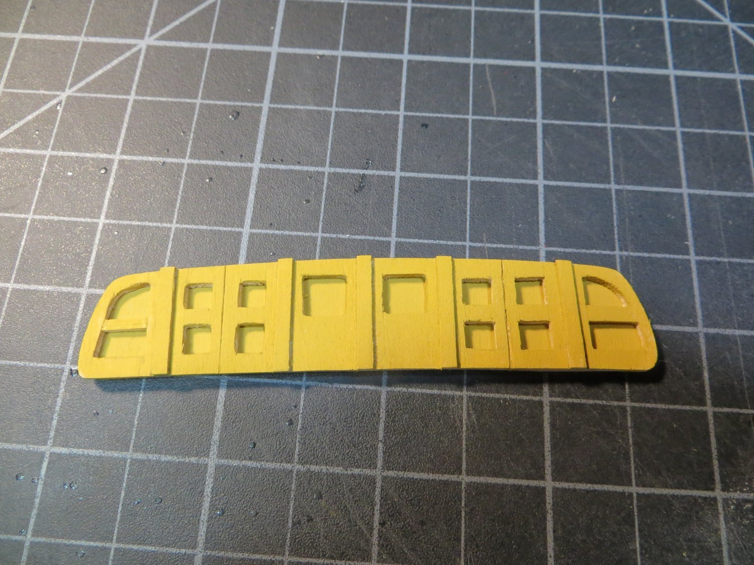
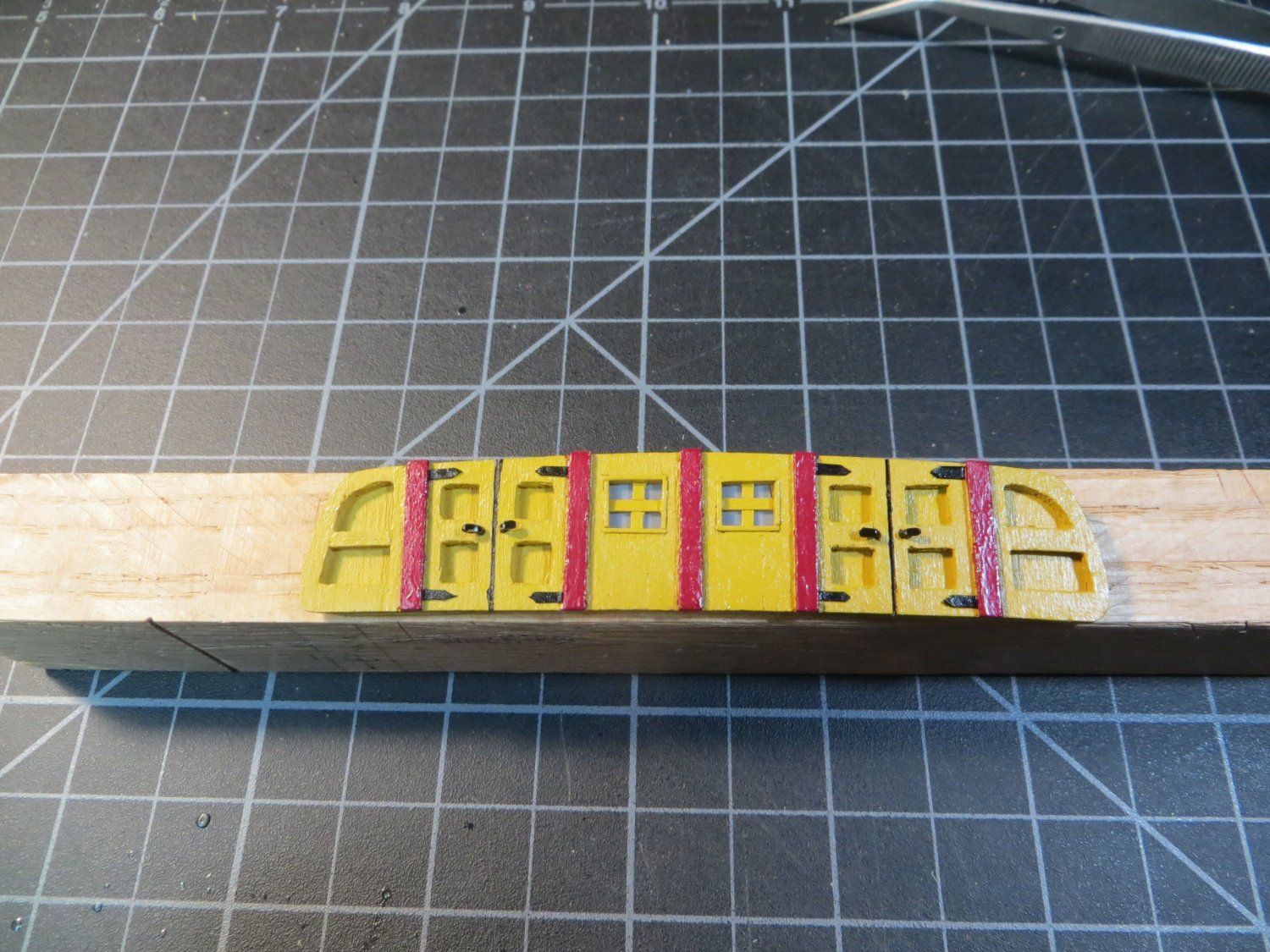
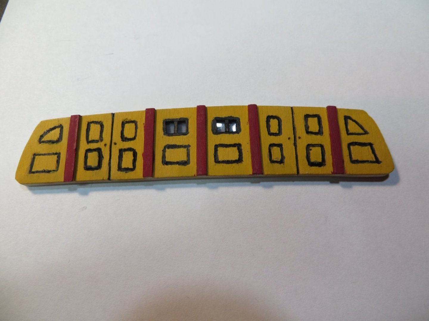
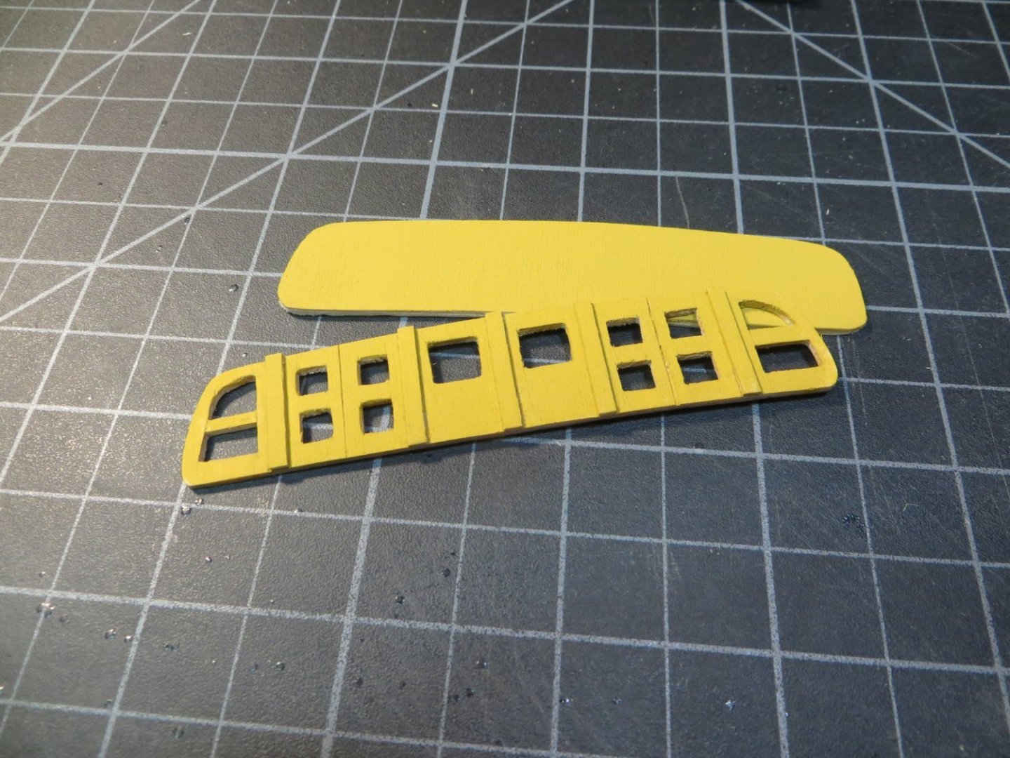
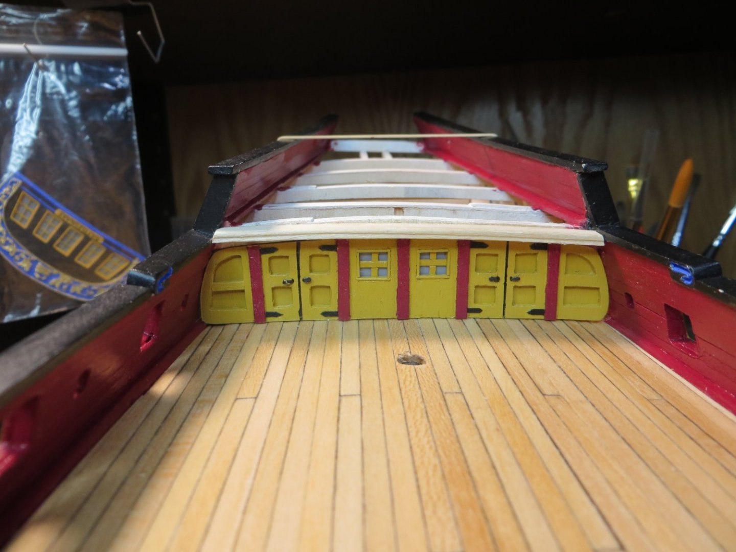
Build/Install Cabin Wall; Stain Gundeck; Attach Transom The cabin wall should be added before planking the Quarter Deck. It just makes it easier to insert the wall and make sure it is straight. I started out by using the BHD I knockout to cut out the initial shape from a 5/32” piece of sheet wood. A lot of sanding was required to get the piece to fit. Then I used my impress tools to make the designs on the wall per the plan. However, when I finished painting the impressions with black paint, I just wasn’t happy with the result. It's really difficult to make a clean impression across the grain. So, I tossed this into the scrap bin and started over. Here is the first attempt. On my second attempt, I made a 2-piece sandwich out of 1/16th sheet wood. It looked to me like this is what Kenneth Powell did in his build log. The inset parts from the plan were cutout of the top piece using an Exacto knife. This was laid over a yellow ochre painted piece behind. I decided to keep it simple by only painting these areas yellow. Then added 5 pieces of stripwood between the 4 sections and painted them red. I made windows out of plastic packaging as before, framed them and attached crossbars. I made some tiny door handles from brass rod and hinges from black card stock. I was much happier with the way this turned out. Before I glued the wall in place, I had two tasks to do. Task #1: I ripped out the beam in front of bulkhead support I. I removed the old one and cut a longer one that was sanded lengthwise to fit. I used my scrappers to make the fancy front edge. I soaked it in water and rubber banded it to the knockout to get the camber. Unfortunately, it didn’t have quite enough bend in the middle. So, I sanded the deck support to make them both flush. I plan to stop the quarter deck flush before this beam. I will stain it the same as the deck, rather than painting it a different color. Task #2 was to stain the gundeck. This needs to be done before planking the quarter deck. I was debating between the Minwax Natural or the Weathered Oak stain. I thought I liked the weathered look, but before I committed, I decided to make a test strip at the very aft of the ship, hidden under the quarter deck. I decided that this stain was too grey looking. So, I went with the Natural stain. I like the clean look it produced. After the hatches, etc. are glued to the deck I will apply Minwax Satin Wipe-on poly. Wood glue won’t stick well to poly. Stained Gundeck Completed Cabin Wall And finally with these recent steps, I finished the stern rail and permanently attached the transom piece. I laid a piece between the side rails and sanded it down to smooth the joints. I could not make any decent looking supports underneath the rail. Space is too small on my model. So left it open. Next, I installed the transom. I glued some extra supports on the stern block to help hold it in place. These were sanded at an angle to match the transom piece. I used Weldbond to attach the transom at all the touch points. Rubber banded it on overnight to allow the glue to set. I think the transom really makes the ship look awesome! I appreciate any of your thoughts or comments. The next step is to plank the quarter deck. Tapering the planks to fit well is always a challenge! Thanks, Ed


-
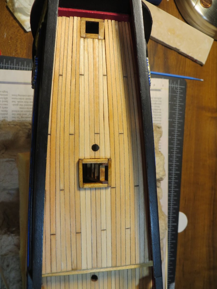
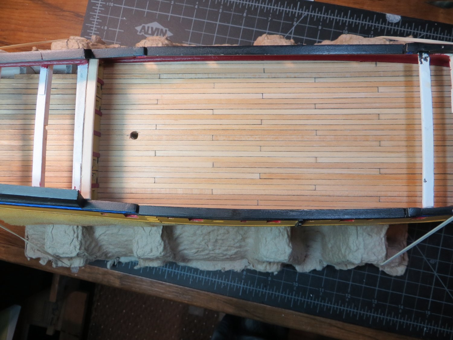
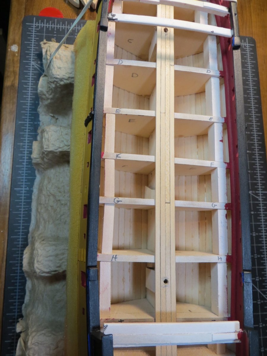
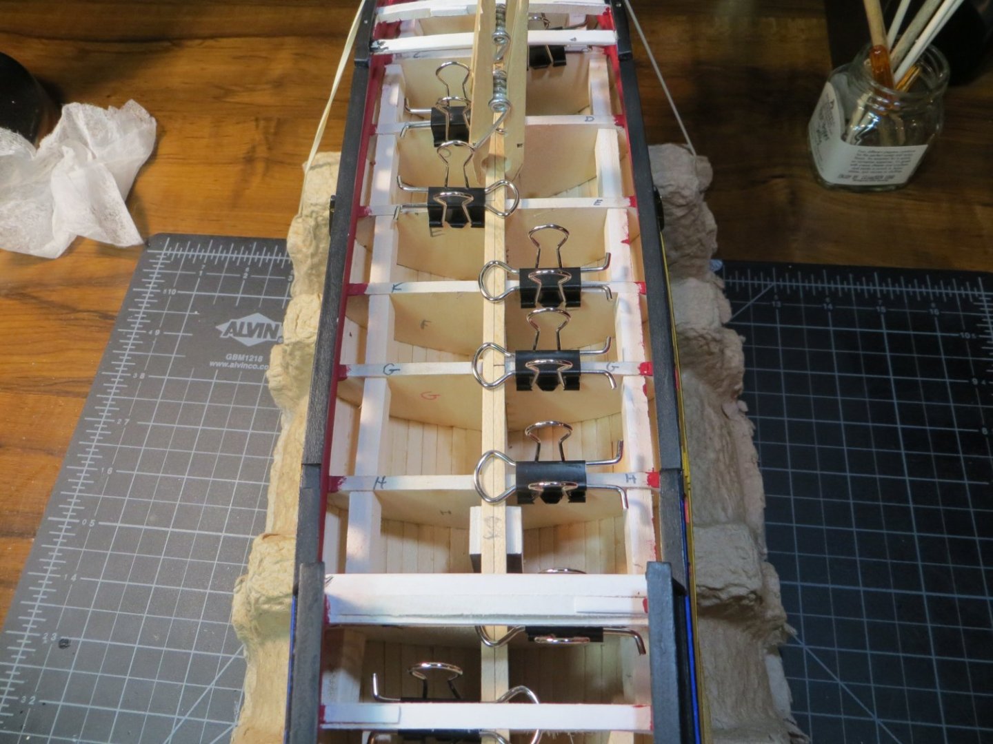
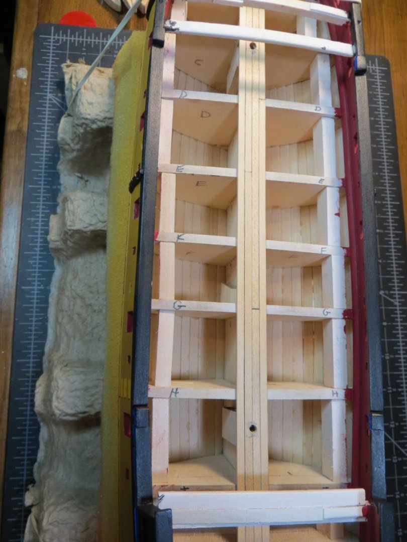
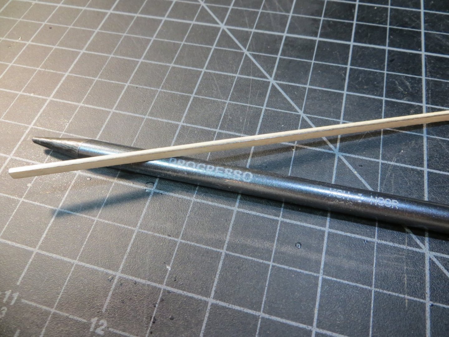
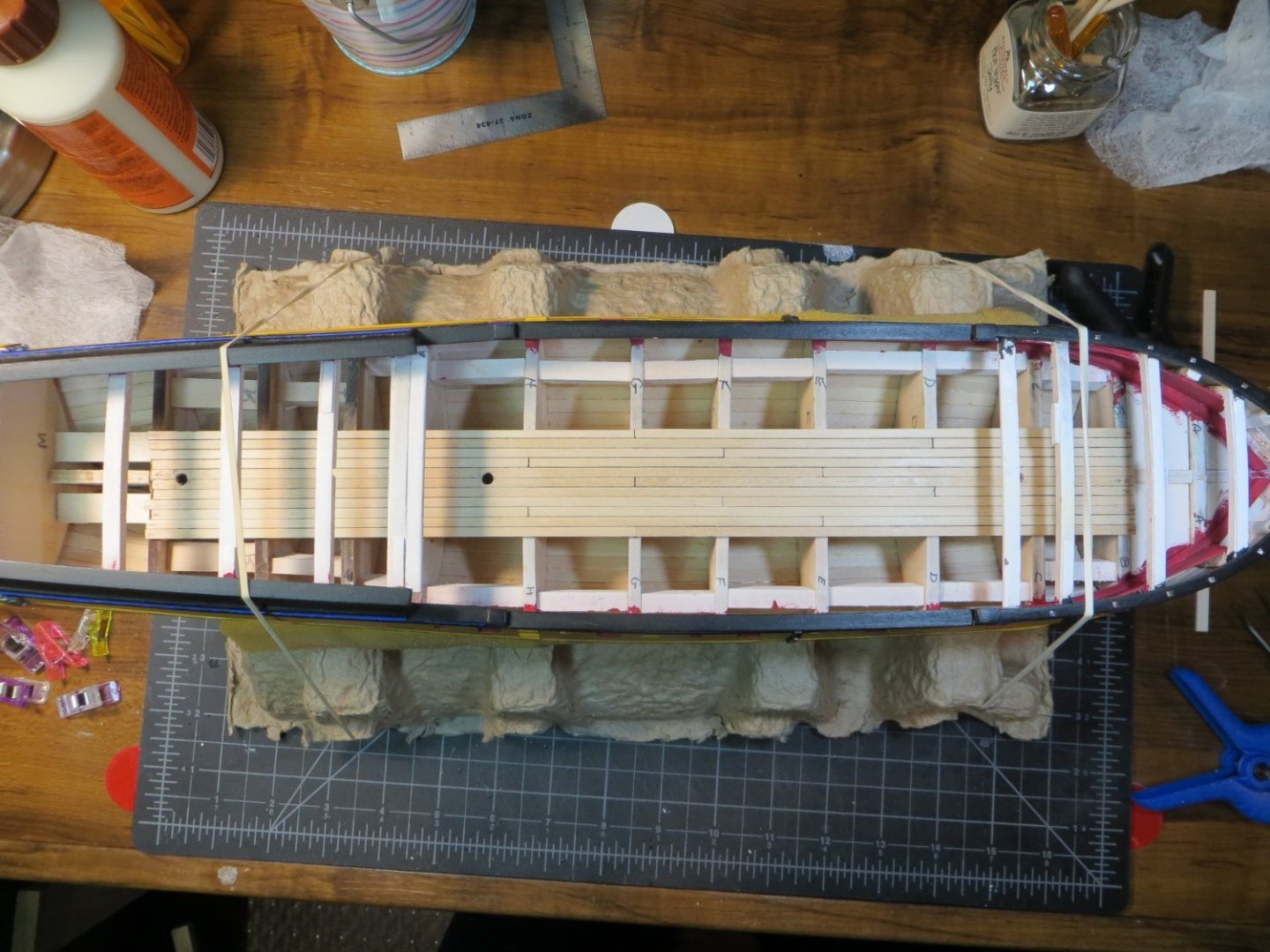
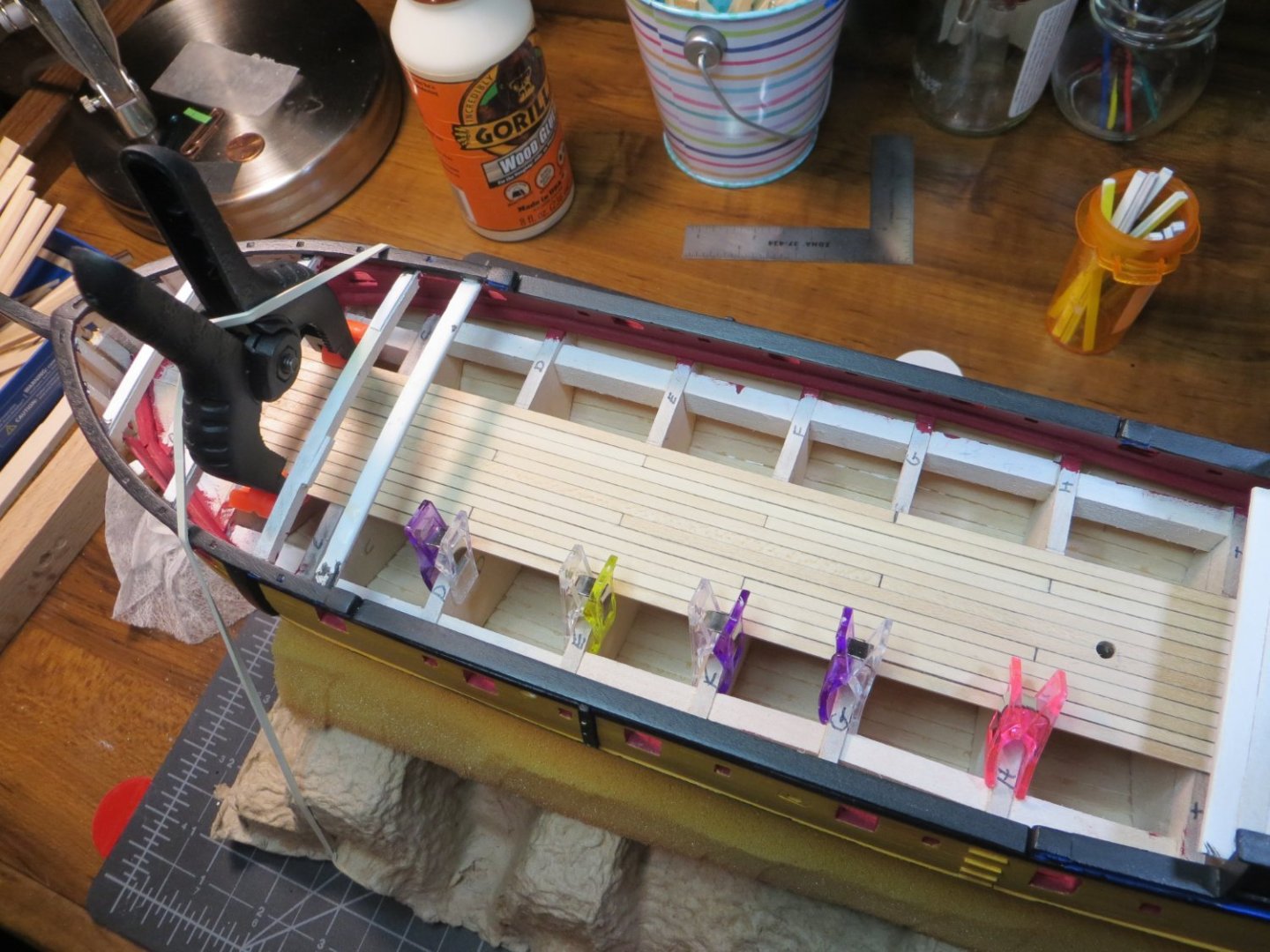
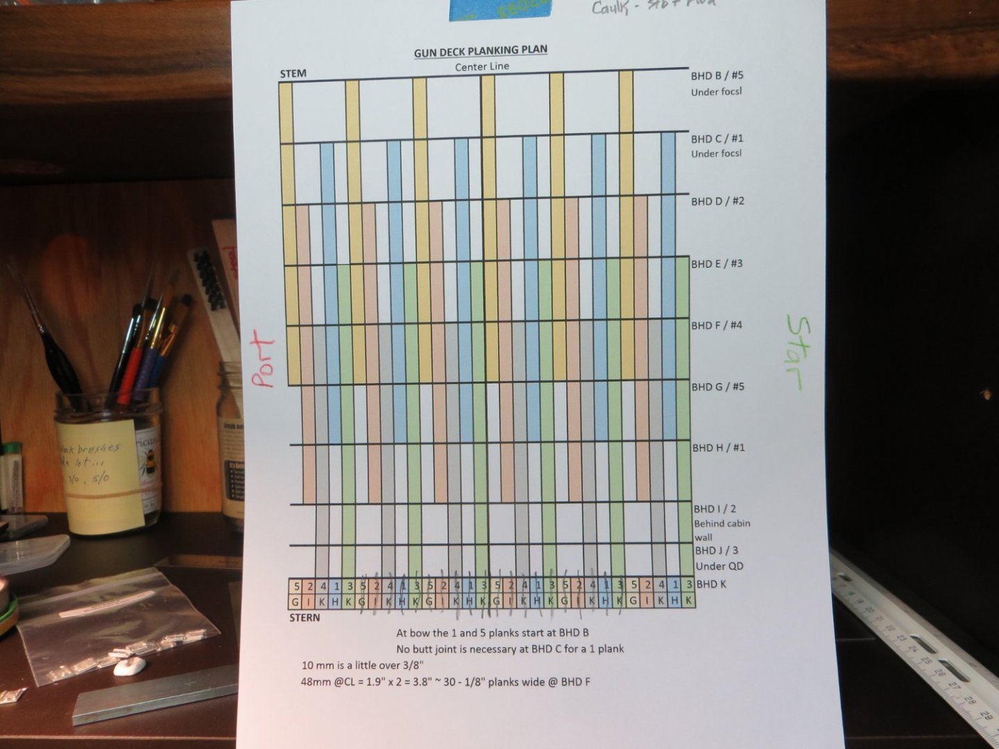
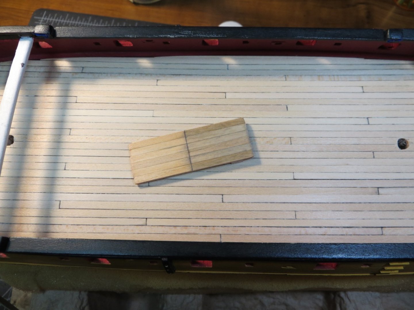
STAGE D – Plank Decks, Install Gunport Lids, Rudder I’m on to Stage D in my build process. This is primarily planking the decks and installing the various parts and pieces that are required along the way. I plan to do the Gun Deck first followed by the Quarter Deck and finally the Forecastle Deck. You could lay planks from stem to stern with no butt joints, but the deck looks much nicer and is more accurate if you cut the planks and insert butt joints. You need to have a plan for staggering the joints. I found an excellent write-up on the NRG forum. This explains it better than I ever could! Here is the link: https://modelshipworldforum.com/resources/Framing_and_Planking/Deck_PlankingIIbuttshifts.pdf I used this on my Bluenose build. It’s called a 5, 2, 4, 1, 3 pattern. The pattern is based on the number of planks between butt joints. In this pattern there is a joint every 5th plank. The joints are set on top of a bulkhead. Start at the center line of the keel and place a #5 plank to the starboard side and a #3 plank on the port side. It is critically important that these are straight and square to the CL. Then I alternate port and starboard adding planks using the pattern. Normally there would be 5 bulkheads covered by 1 plank. I did not run the deck strakes the full length from A to M on the gun deck since the ends are covered by the Focsl and Q-Decks. So, no joints were inserted under the focsl or aft of BHD I, which is under the cabin wall. This resulted in just needing 1 butt joint between bulkheads D and I for each run. I simply extended the plank on each side of the joint to either BHD B or to L. I decided to plank under the quarter deck so that the hole for the stairsteps didn’t reveal any unplanked areas. I made BHD B the #5 in order to make everything come out the way I wanted. Here is the Gun Deck Planking Plan I made for myself I laid the two planks at the center line simultaneously to keep them straight and square to the bulkheads. The #5 plank stops at BHD G. The #3 plank butts on top of BHD E. I used this type of lead pencil to color the starboard edge and forward edge of each plank to simulate caulking. This really stands out after the deck is stained and sealed with polyurethane. If you look closely, you can see the black on the edge of the plank. Next the #2 plank (BHD D) was laid on the starboard side and #1 (BHD H) on the port. At this time, I also drilled holes in the deck planks where the mast holes need to be located. More planks are added on each side As the planking fills the space it gets harder to use clips to hold them in place. Eventually I just had to use my fingers to hold planks in place At the end, I simply rounded off the forward edge to match the curvature of the waterway. On the last 2 planks I glued the small partial plank to the longer one just inside of it. I sanded them until the whole assembly fit into the gap. Then glued them in place as a single piece. I inserted a piece of a bulkhead cutout just behind the slot for the bowsprit at BHD B. I painted it the same red color as the bulwarks. This will block the view of the unfinished part of the ship under the focsl deck. Here is a good view of the finished gun deck The next step is to stain the gun deck. This needs to be done now, because I will not be able to access under the upper decks once they are installed. I also need to set-up the 4 cannons that will be located under the focsl deck. It seems that a lot of Rattlesnake builders leave the decks unstained and just apply some varnish or poly. I like the richness that comes from the stain. I’m considering 2 options. In the picture below I test stained the piece of mini decking I made for the cannon gunport checks a while back. On the left is Minwax Natural and on the right is Weathered Oak. My wife likes the Natural. She says the Weathered Oak looks dirty. I’m looking for some feedback. What did you use or what do you plan to use? Which of these do you like? As always, I appreciate everyone’s feedback. Thanks, Ed
-
Hi John, Thanks! It took a bit of work to get them looking halfway decent. I used some mini-files to reshape the metal. Then I used a pointy burr in my Dremel to deepen some of the spots where they just left a pool of molten metal. I used sanding sticks to smooth the edges and finally a polishing wheel on the Dremel to get all the tarnish off. I'm satisfied with the way they turned out. I used the same prep on the transom decoration. But, since there was more space to work between the carving and the background, I decided to just brush paint blue color directly. I didn't try to use the alcohol wipe method on it. I like your Gunport lid. I have to figure out how best to do mine, since I didn't put any holes for them on the stern. Keep up the good work! Ed
-
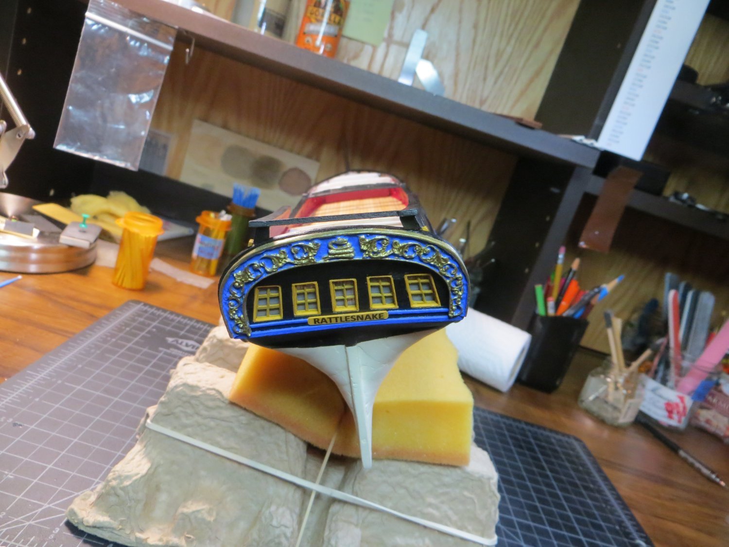
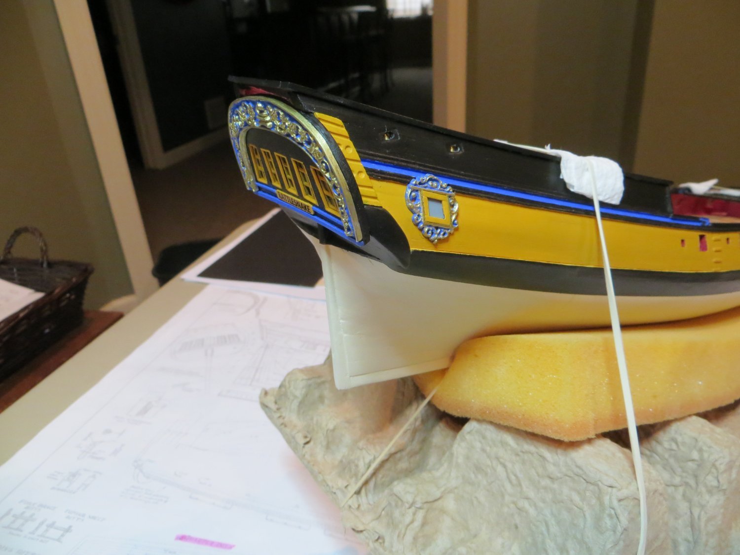
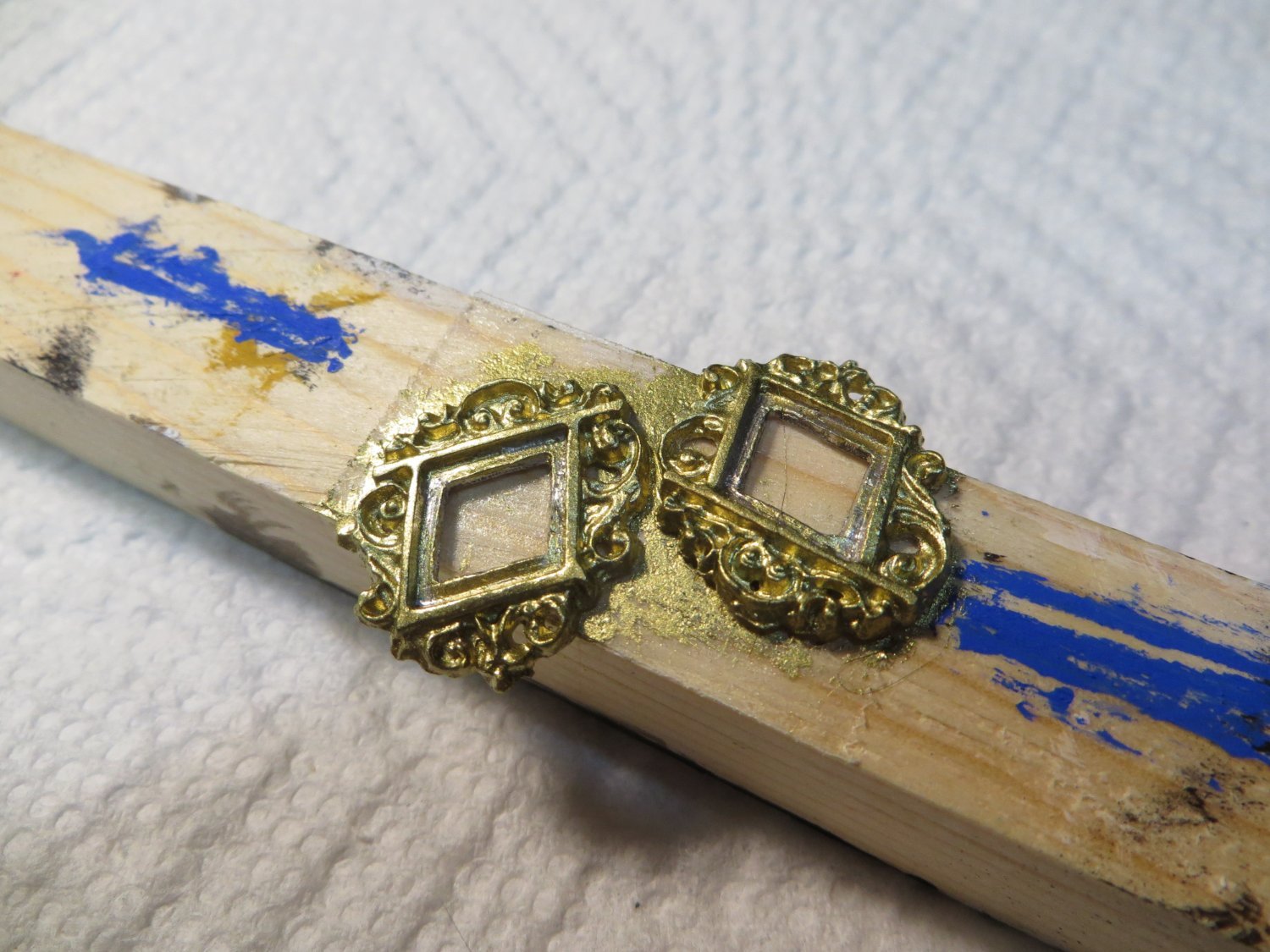
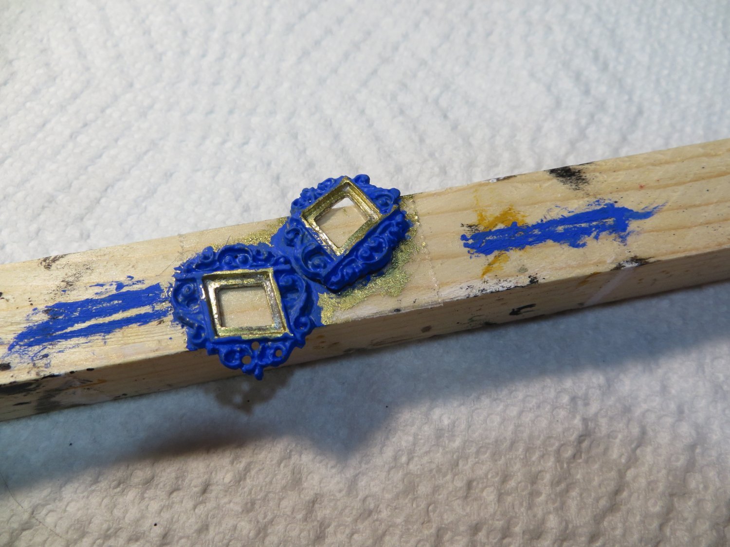
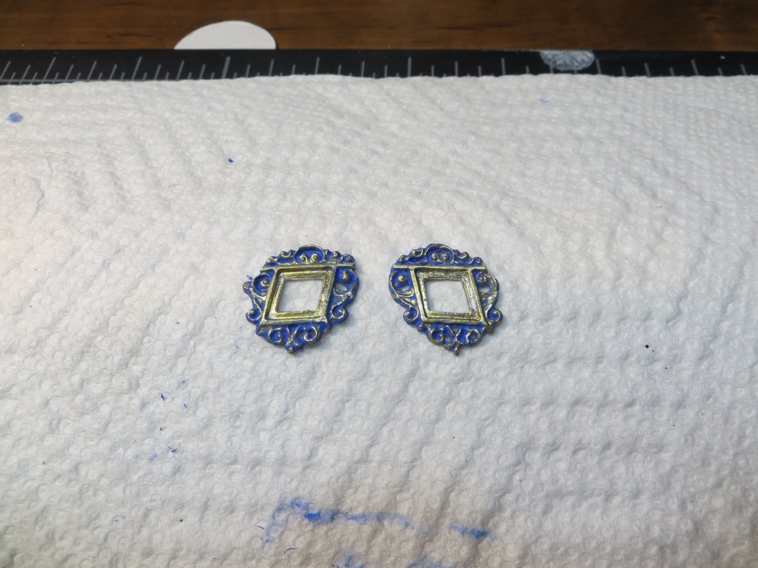
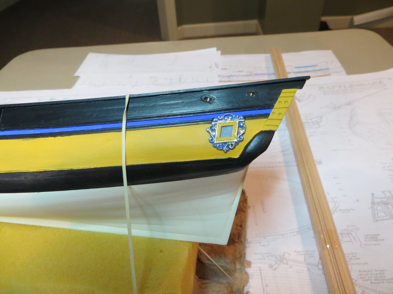
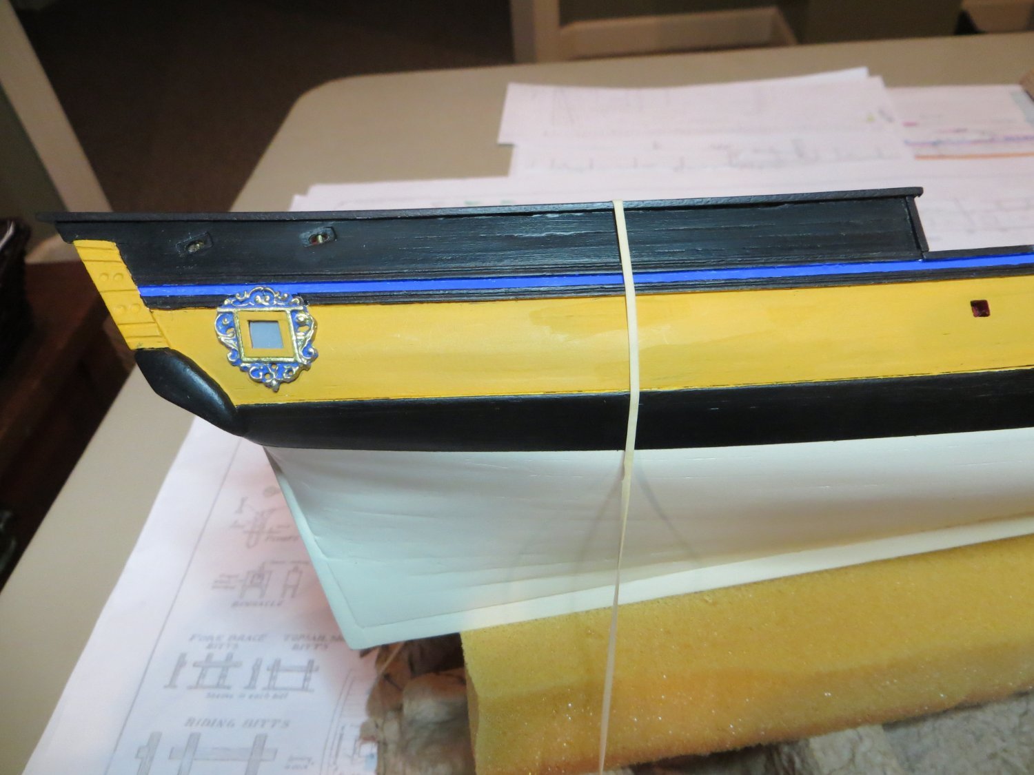
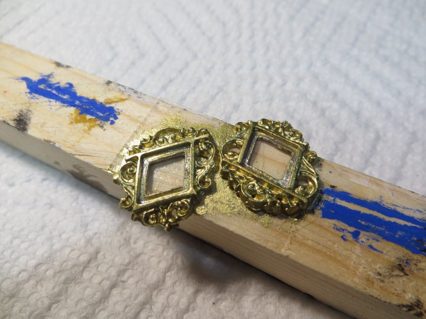
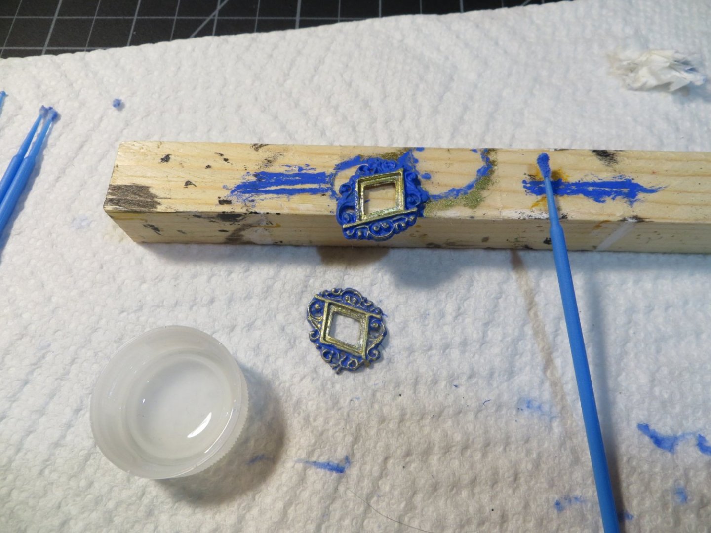
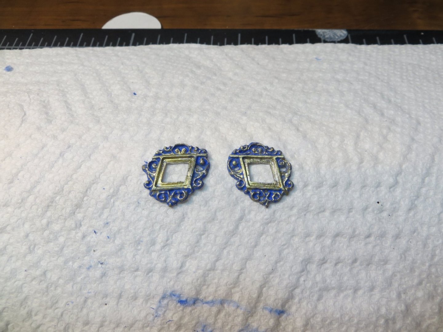
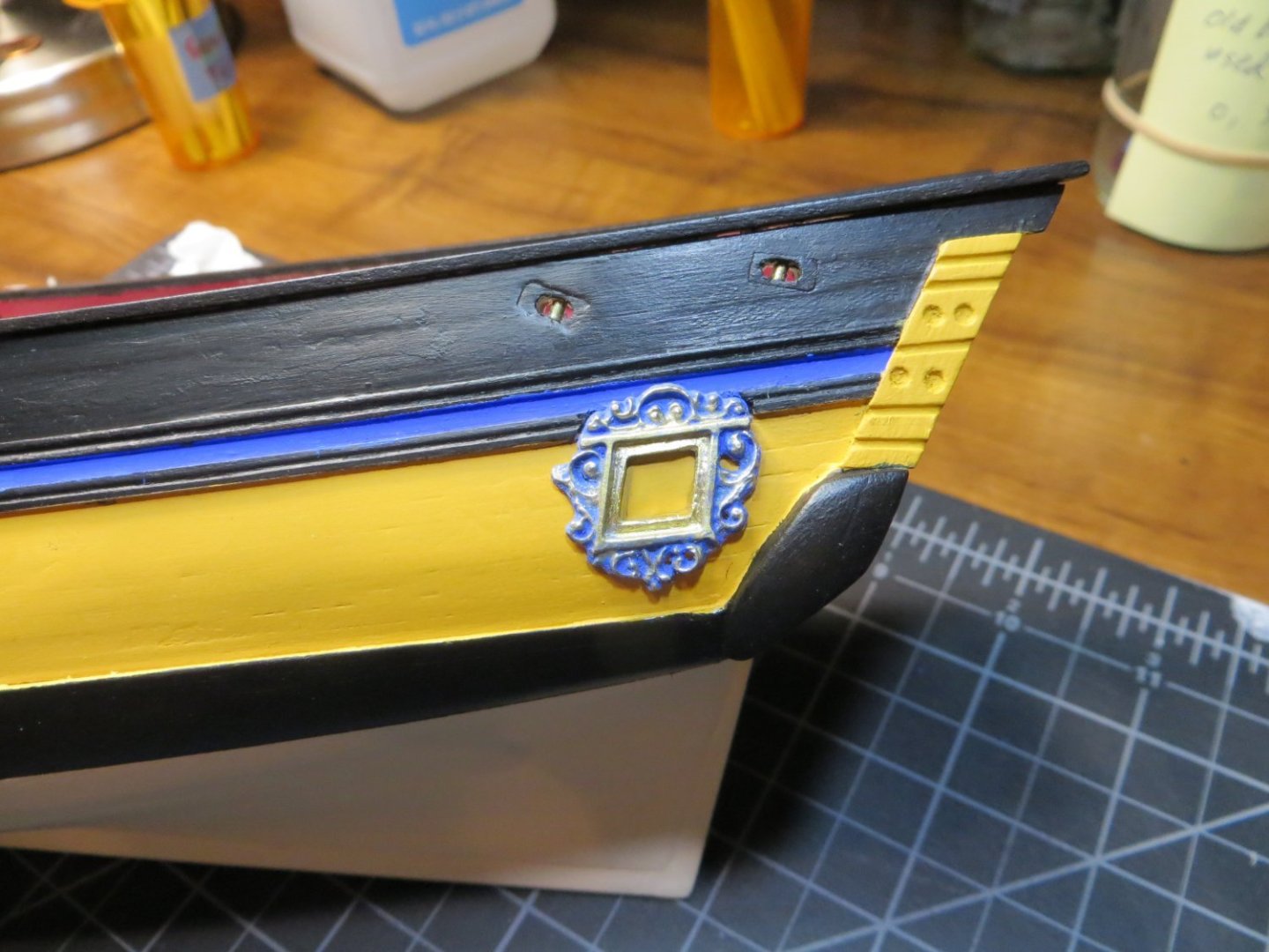
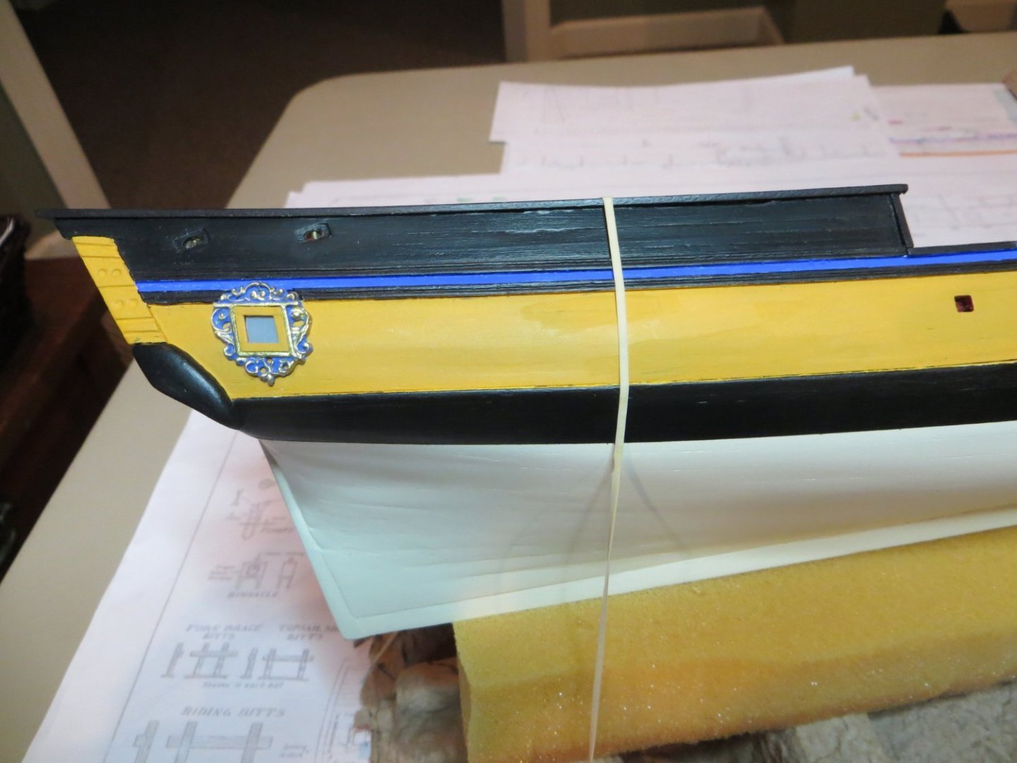
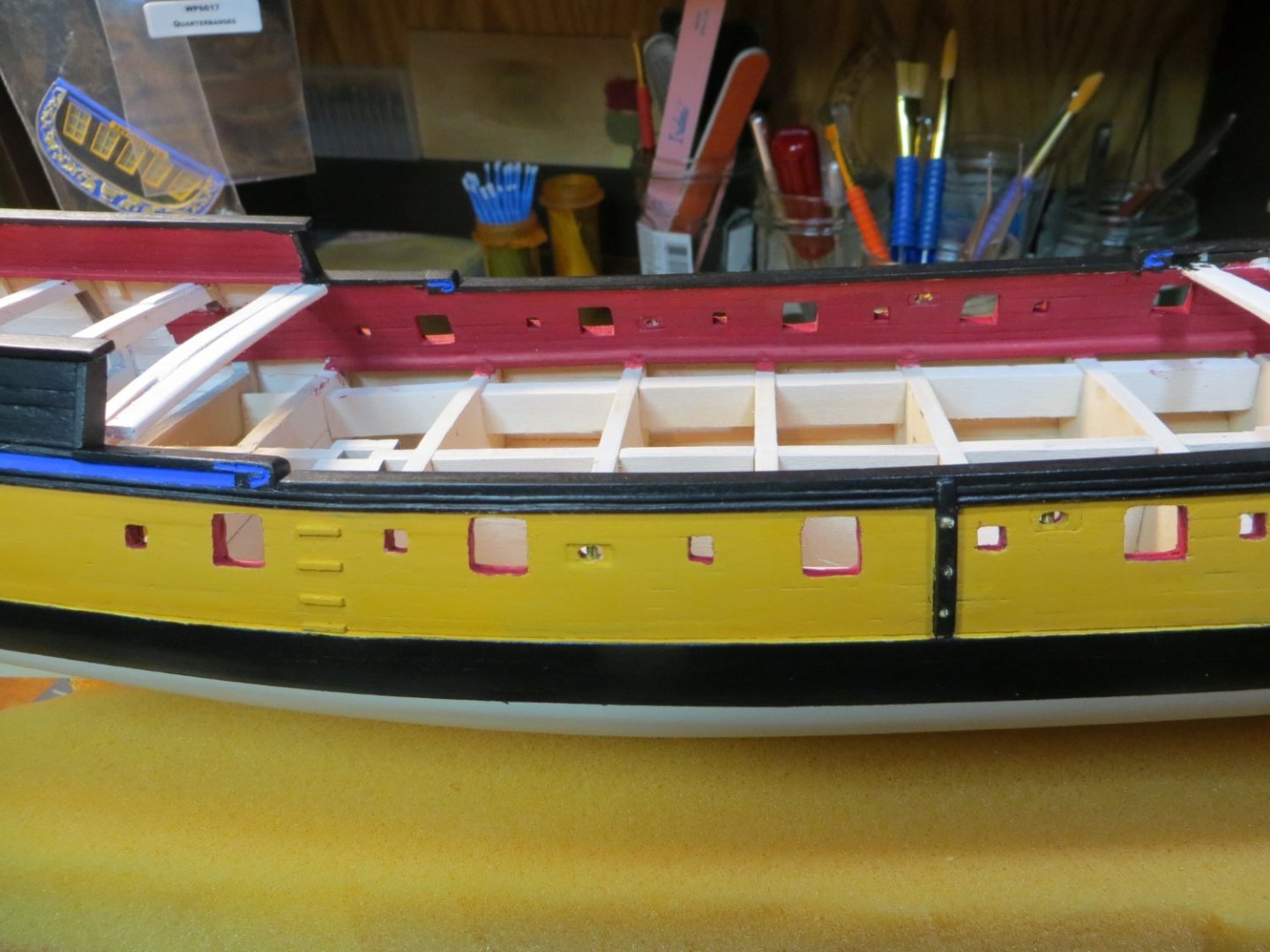
PAINT & ATTACH THE QUARTER BADGES Before starting to work on the decks, I decided to complete the Quarter Badges. I cleaned them up earlier when I needed to mark their position relative to the molding strips. Now I needed to paint them and add windows and frames. I wanted to use a paint scheme that was similar to what I used on the decorative transom piece. The plan is to have a base layer of ultramarine blue and gold (actually it’s Testors brass enamel) on the carvings. In order to achieve this, I used a technique I found on the forum. I can best explain this by showing pictures of the process. Step 1 is to paint the badges entirely with the brass enamel. This takes 48 hours to dry completely. Step 2 is to paint the badges entirely again with the blue Step 3 is to use isopropyl alcohol to rub off the blue and expose the brass underneath. I use a dental cotton swab to do this. I only allowed the acrylic blue paint to dry for about 30 minutes before rubbing it off. The quarter badges after removing the blue from the carved areas Step 4, I came back with a super fine brush and touched up the brass to make it look brighter and crisper. Here is what it looks like on the ship before adding the windows I added “windows” made from clear plastic packaging. This was painted on the inside with blue-gray acrylic like on the transom windows. Window frames were made with really small stripwood and painted with yellow ochre. Here is what they look like after gluing them to the hull I’m working on planking the gun deck now. Thanks for looking in! Ed


-
Hi John. Thanks for the comments! First off, I do not like the Model Shipways paints. I had a lot of problems with the ones I bought from them for my Buenose build. I returned them for a refund, but they said they never received them. So, I was out the money and the paint! Very disappointing. Since then, I found that Vallejo paint works the best for me. Vallejo calls the color Ultramarine Blue. I mistakenly identified it as "aquamarine" blue in my post. It's one of their Model Colors, not Model Air. So, it's thicker and made to be brushed on. I spent a lot of time working on the color scheme. I knew what colors I needed and I studied the color pallet for Vallejo paints to find the shades I liked best for each color. I identified 3 builds that I liked and made a spreadsheet. Then I made notes on what I liked and disliked about each one. I kept making adjustments and finally came up with the combination that you see. I'm very happy with the way it turned out!
-
Thanks Dave! The saying goes, "Imitation is the sincerest form of flattery"!! If you are interested, I can provide you with the Vallejo paint colors that I used. I hope to see you back in the shipyard before too long!
-
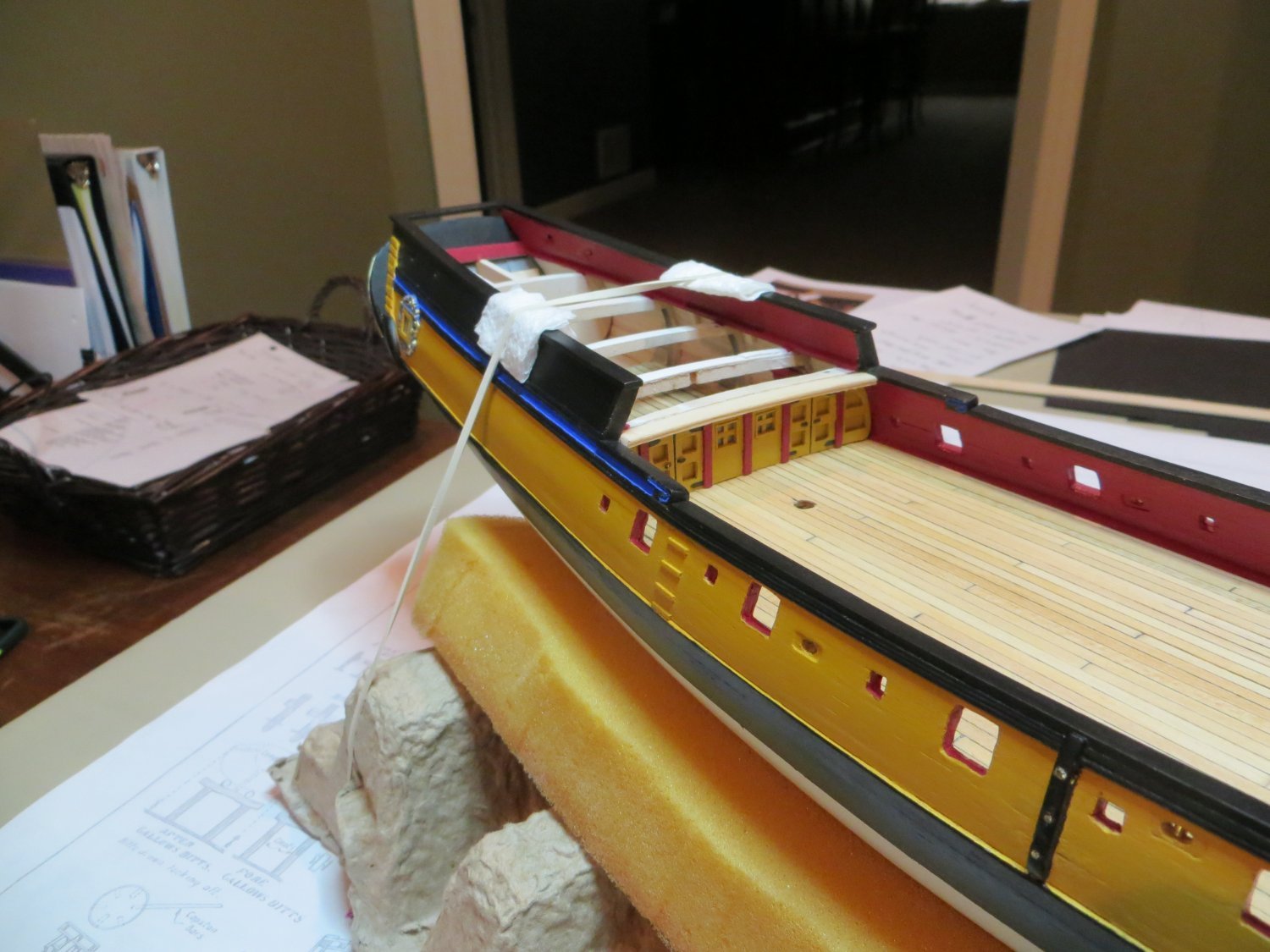
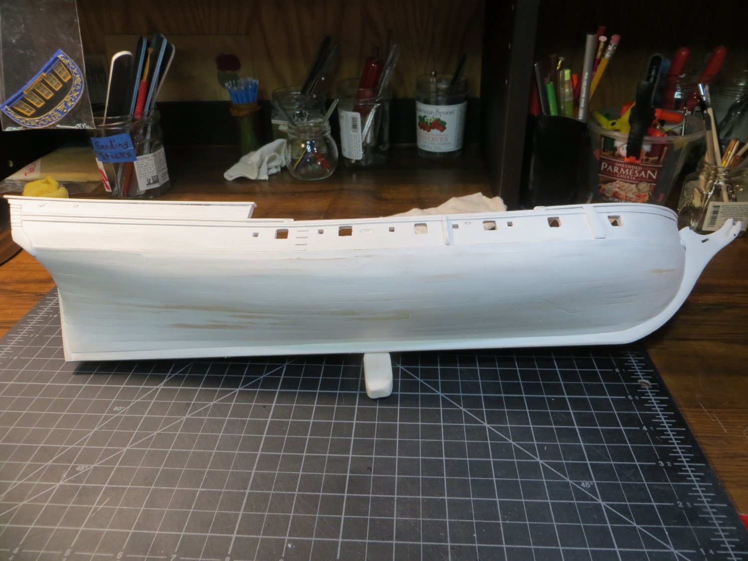
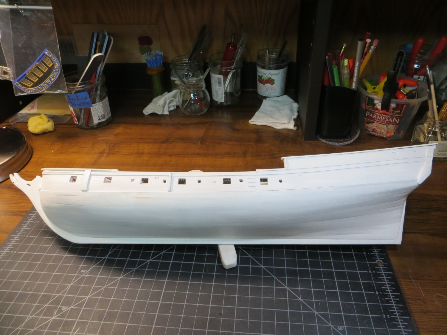
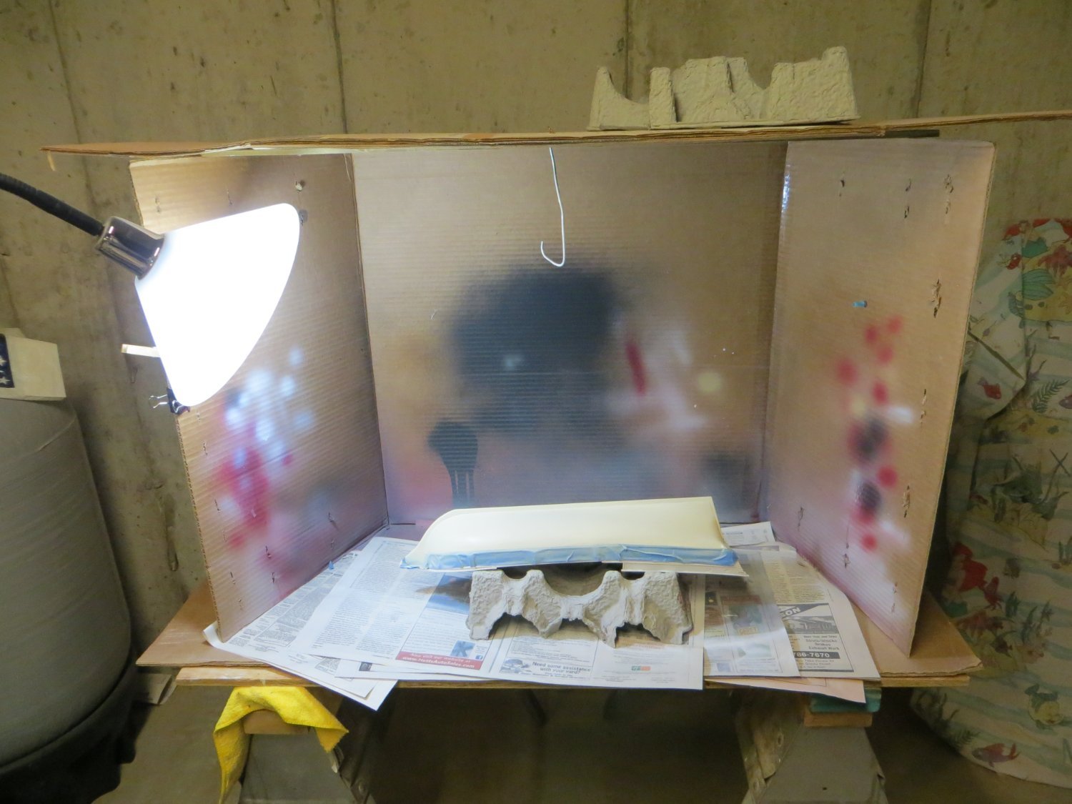
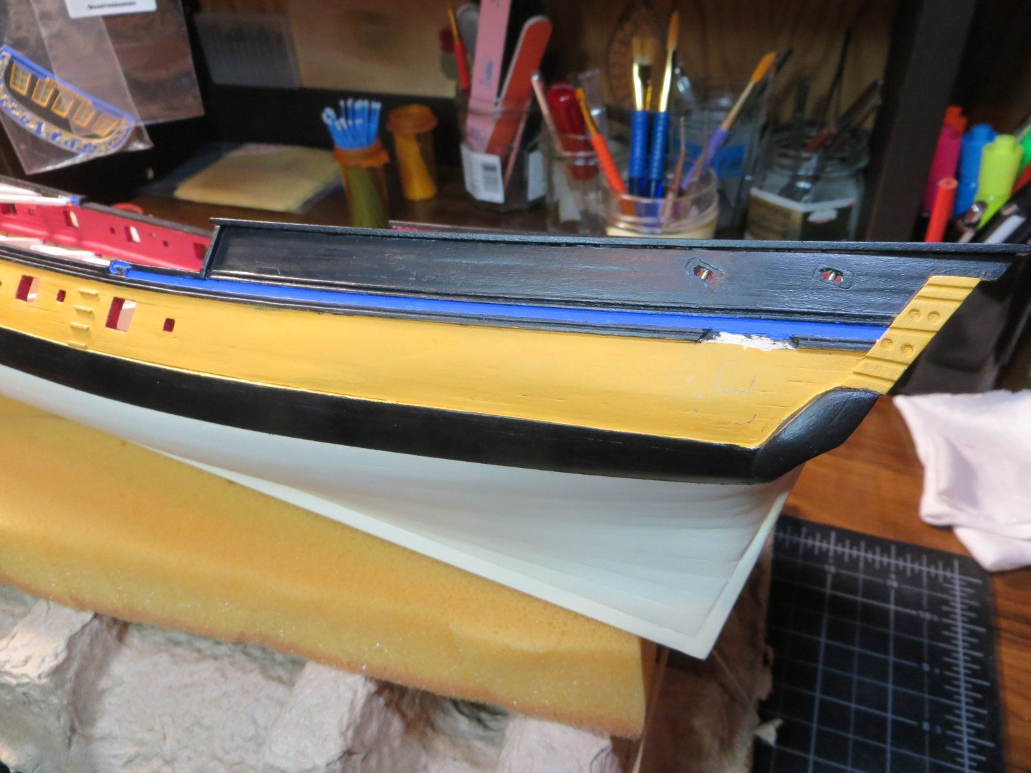
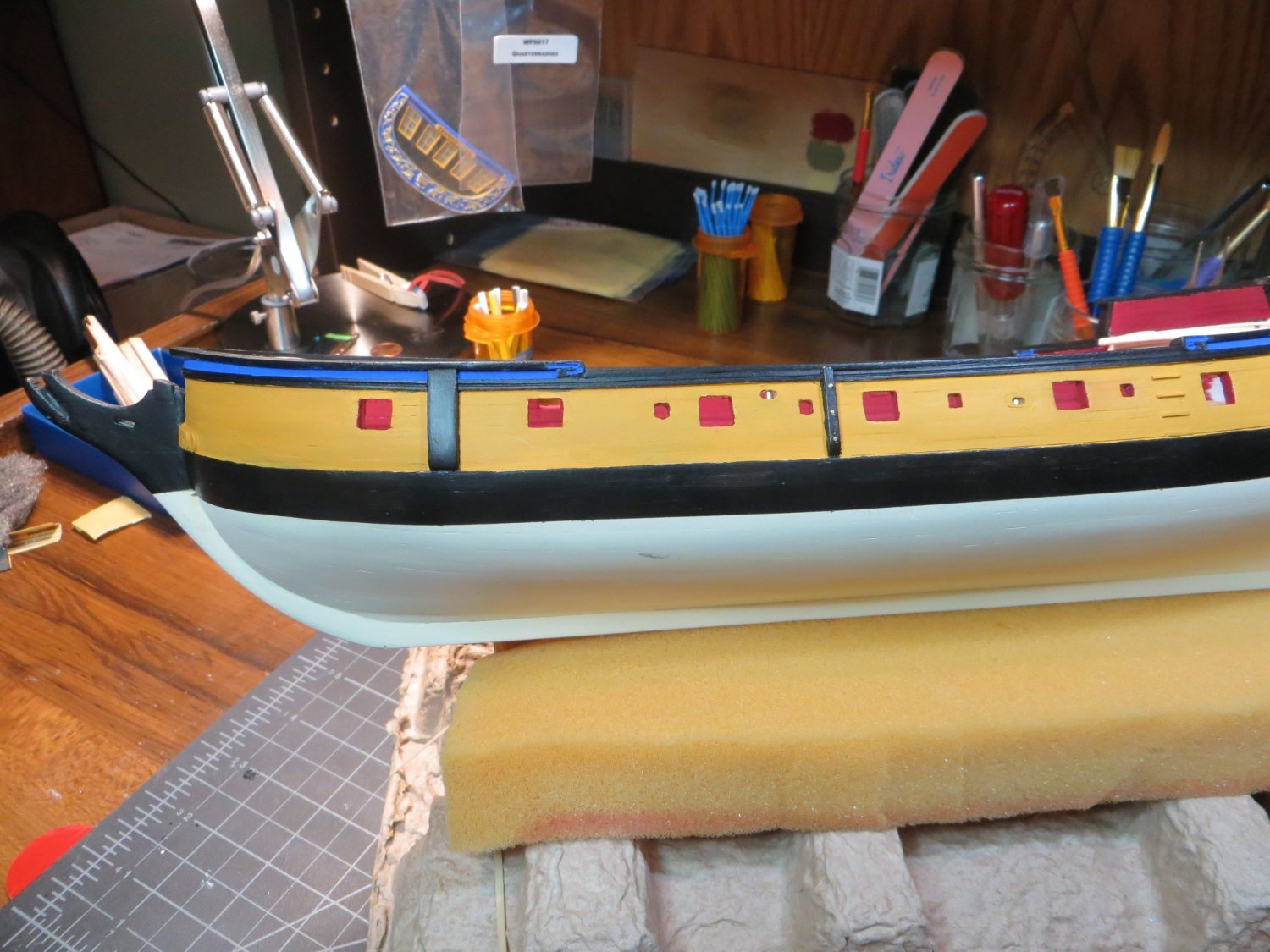
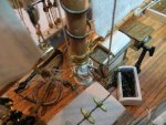
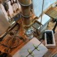
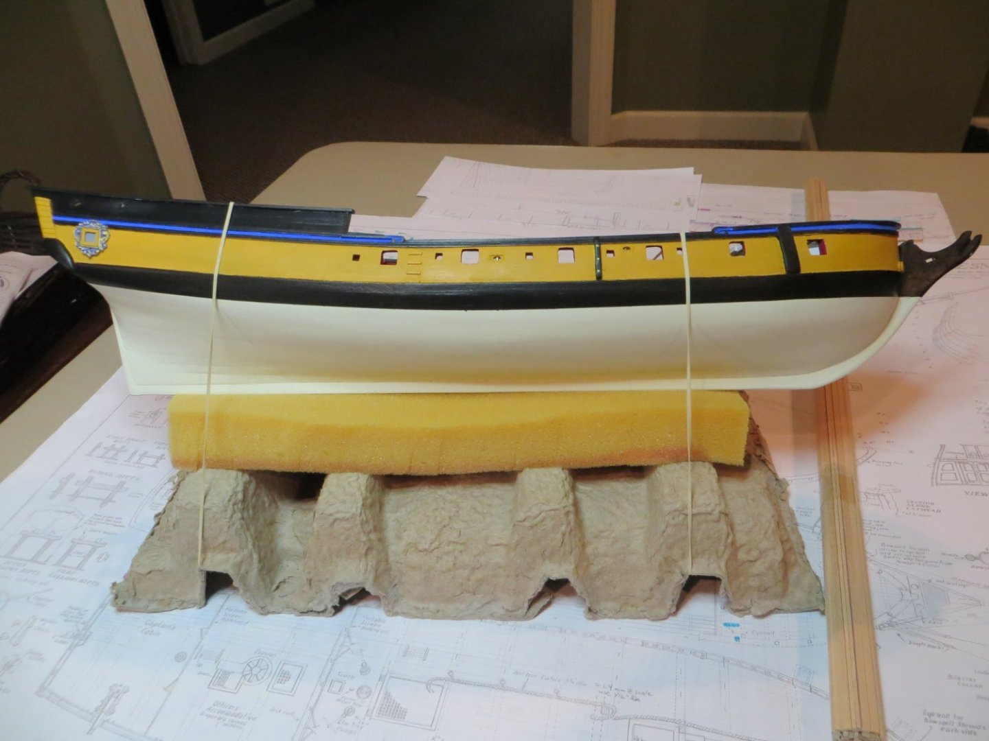
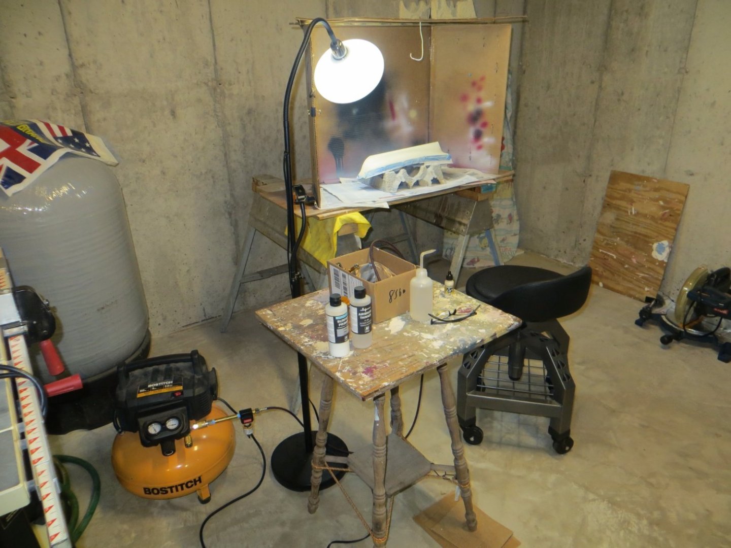
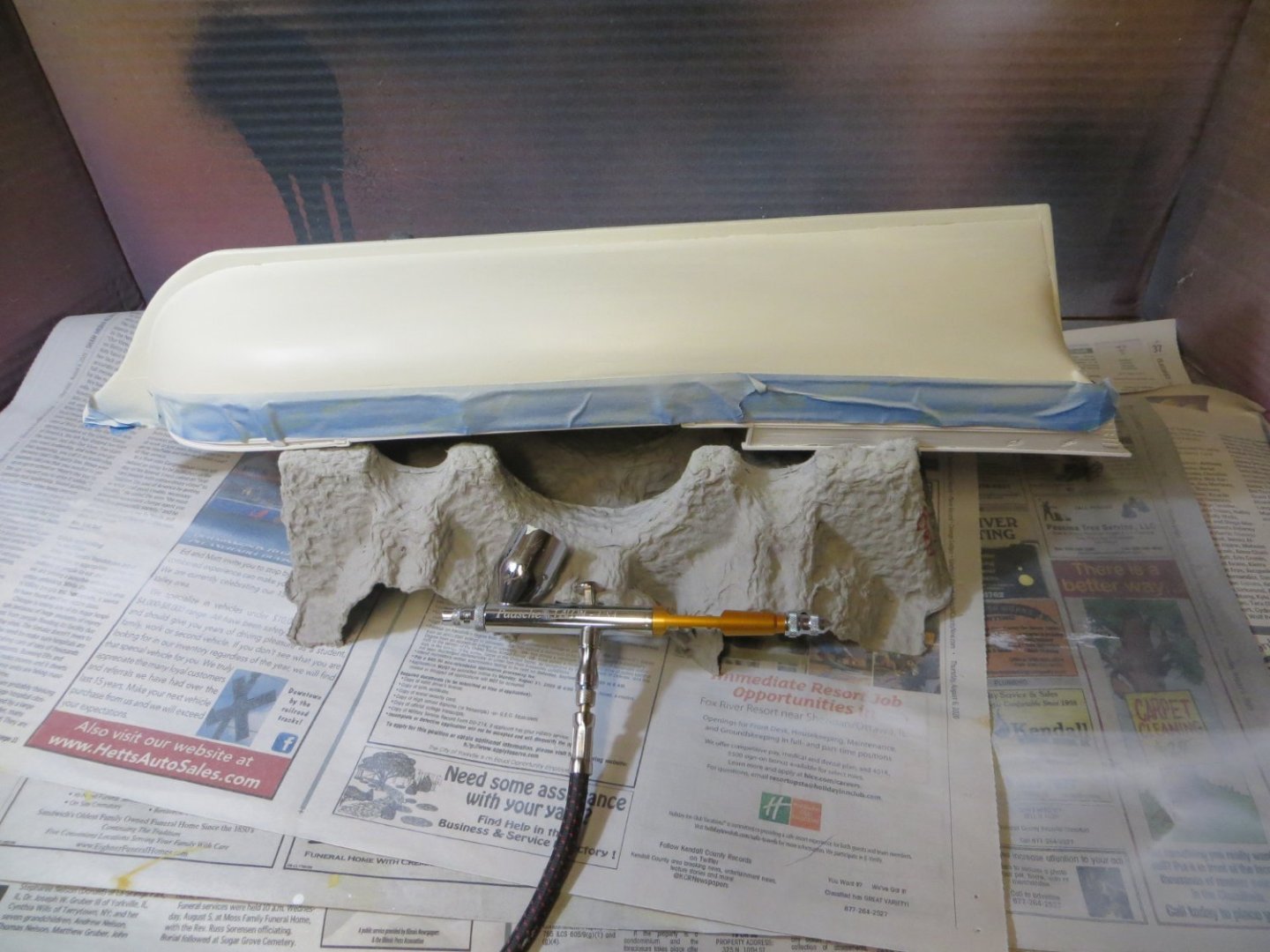
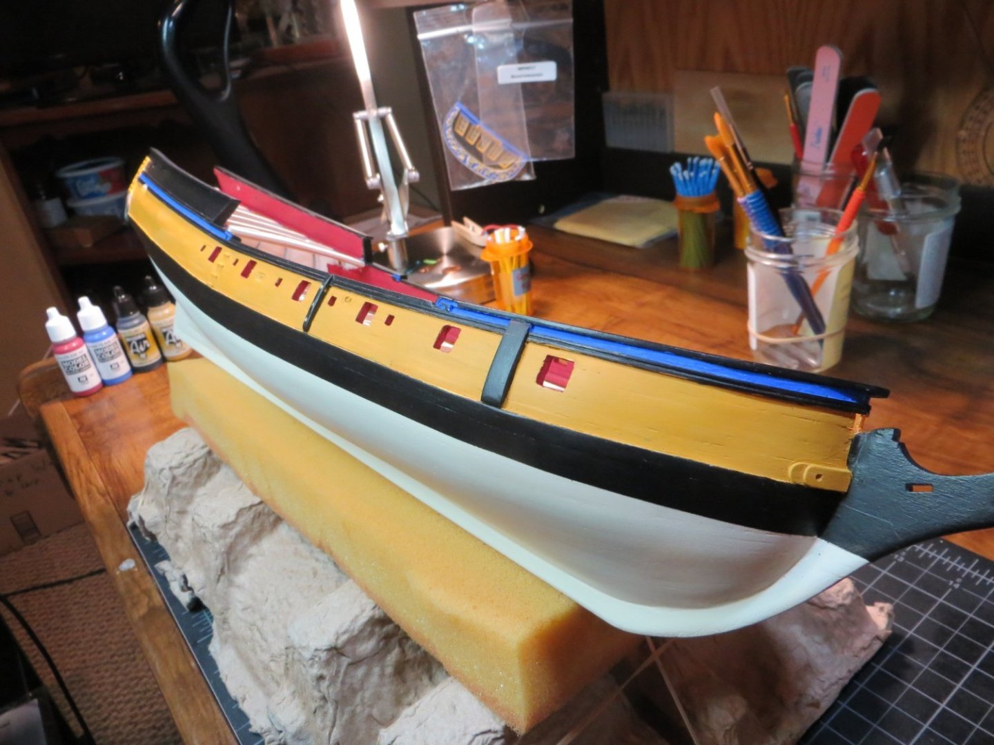
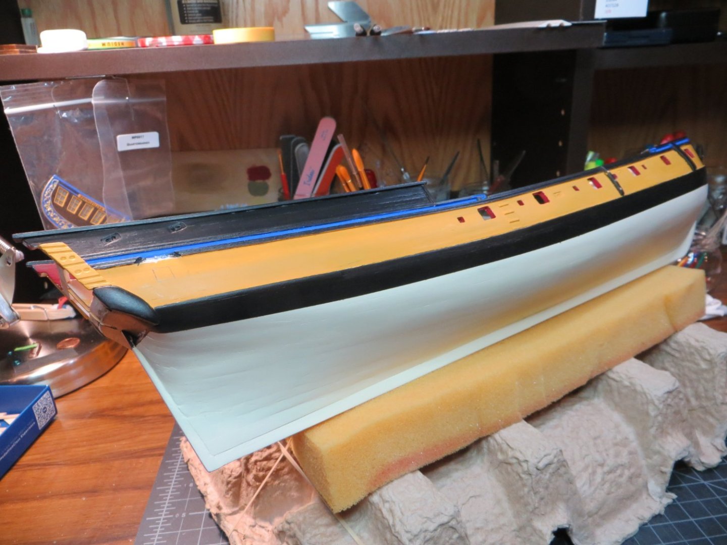
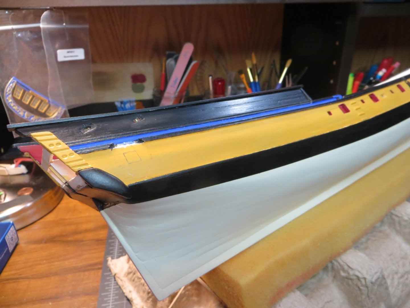
Step 32: PAINT THE HULL I just hit another milestone on my Rattlesnake. I finished painting the hull. I used a combination of airbrush and hand brush painting to apply 4 colors: Tallow or Ivory below the waterline, Black & Yellow Ochre on the outer bulwarks, Red on the inside bulwarks and Aquamarine Blue for accent trim. But the first step was to Airbrush Tamiya white primer over everything that was to be painted. Primer really brings out the imperfections in the planking job! I spent some time adding more filler and sanding to smooth things out. But I didn’t go too crazy with the filler! Here are pictures after a couple of rounds of priming and sanding. Now I’m ready to paint some colors. It’s best to start with the lighter color paint and end with the black. Next, I taped off the upper hull in preparation to airbrush the Tallow below the waterline. I actually taped just below the Wale, since I didn’t care about getting this whitish paint where I was planning to paint the black. Here are a few pictures showing my operation in the middle of airbrushing the tallow. I took a couple of shots of the area in the corner of my basement where I have my homemade paint spray booth set up. Thought maybe a few of you might be interested? The last shot includes my Paasche Talon airbrush. I’ve had good success with this airbrush. But you really need to use paint that is made for airbrushing. Otherwise, it tends to plug up, even when you use thinner. For the next step I reapplied with a hand brush the red on the inboard bulwarks. I did 3 more coats. Next, I taped right at the Wale using Tamiya yellow tape. This stuff really forms a nice tight seal. Then I used regular masking tape to cover the lower hull with a plastic grocery store bag to protect the tallow paint. I also plugged the gunport and oar port holes. I bought a set of various size widths of automotive detail tape for my last ship. I found the width that fit perfectly in the strake that would be painting aquamarine blue. Then I airbrushed the Yellow Ochre. I applied at least 5 thin coats. I decided to hand paint the black. I started at the top with the quarter deck and railings. Then I taped off the area between the wale and the waterline before brush painting the black there. Finally, I removed the automotive tape and painted the aquamarine blue stripe on this strake of planking. After some touch-up work, I took the following pictures. I’m working on the Quarter Badges right now. Then the next big task is the decks. I’m going to wait until the decks are done before installing the Focsl railings. Just another item that is susceptible to breakage! Thanks for looking in! Ed


-
STAIR STEPS I got the stair steps installed on both side of the ship. I used a 1/32" square piece of stripwood to cut 1/4" long stair steps. I made a little cardboard jig to get the length and spacing uniform. Here are a couple pics. I am in the process of painting the hull with primer. Had to break out my airbrush for this. Took me a little practice to get back into the groove with airbrushing. I'll post some pictures when I've got it ready.

-
I'm going to assume you mean steps on both the starboard and port side. It makes sense to me too. Thanks Gregory!
-
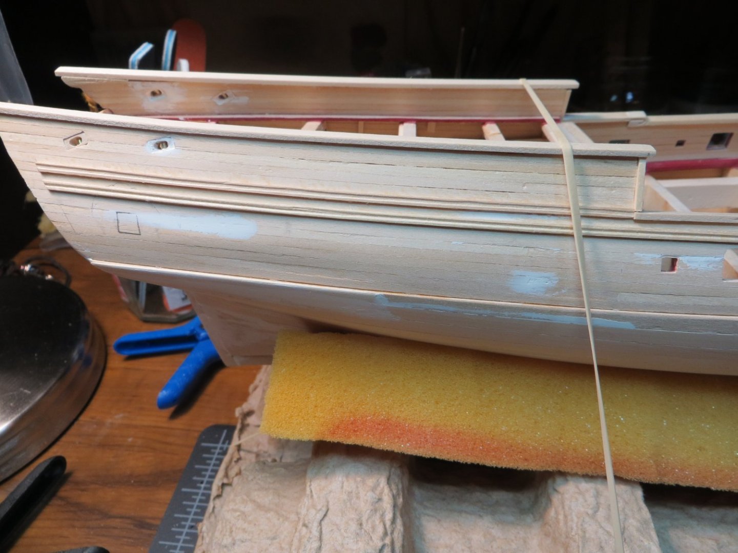
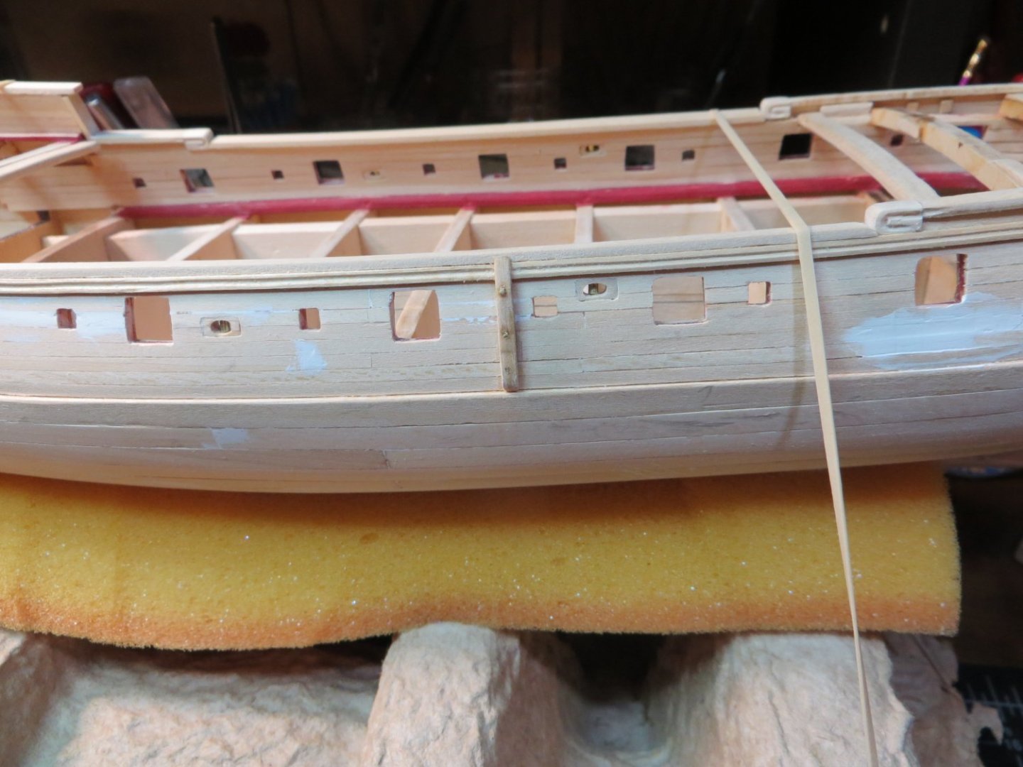
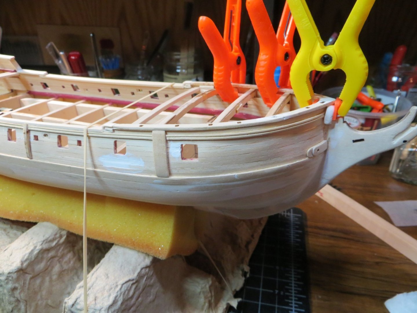
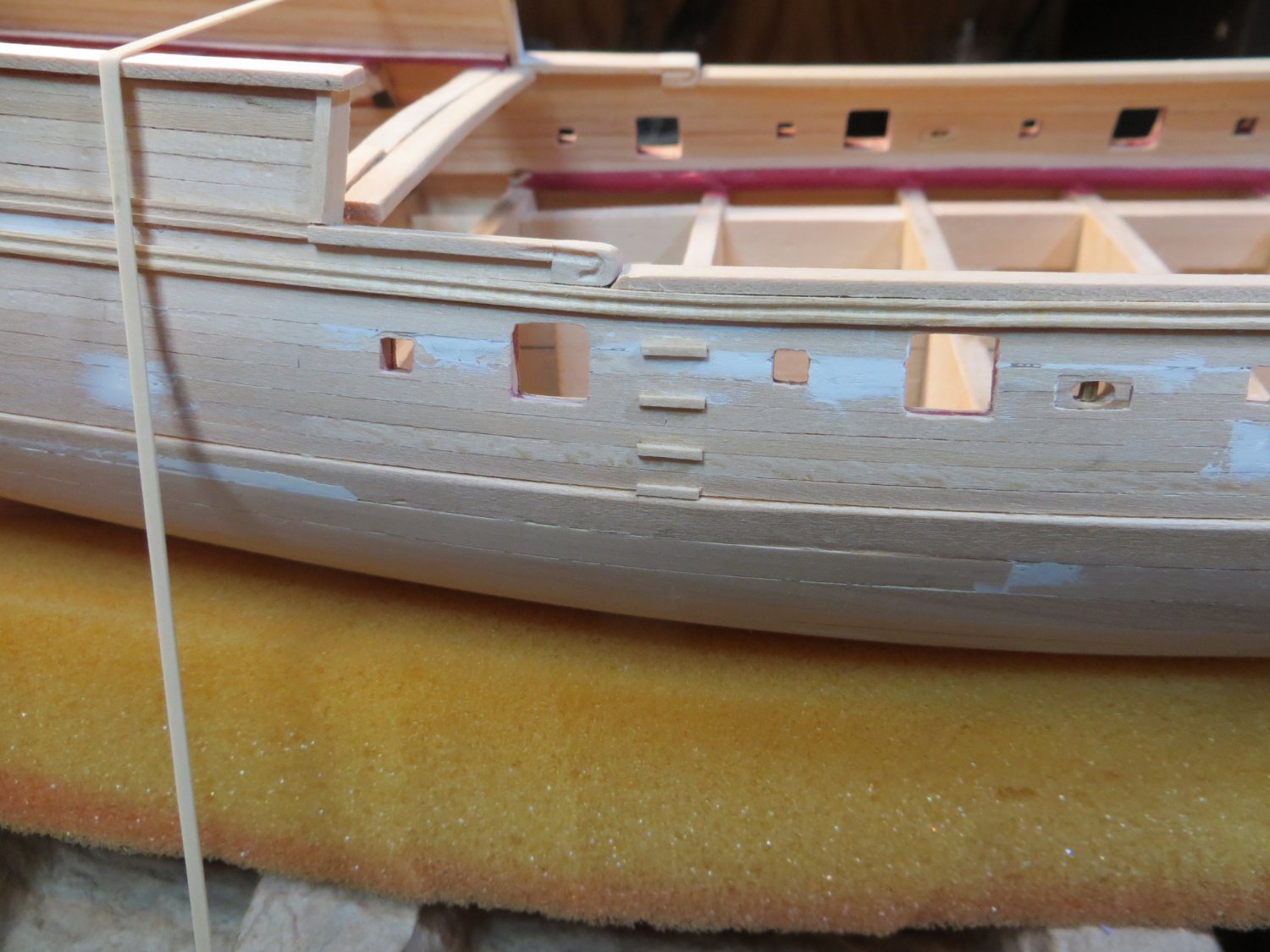
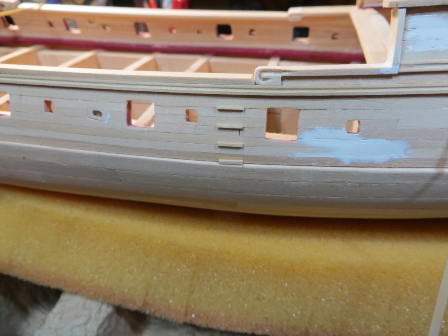
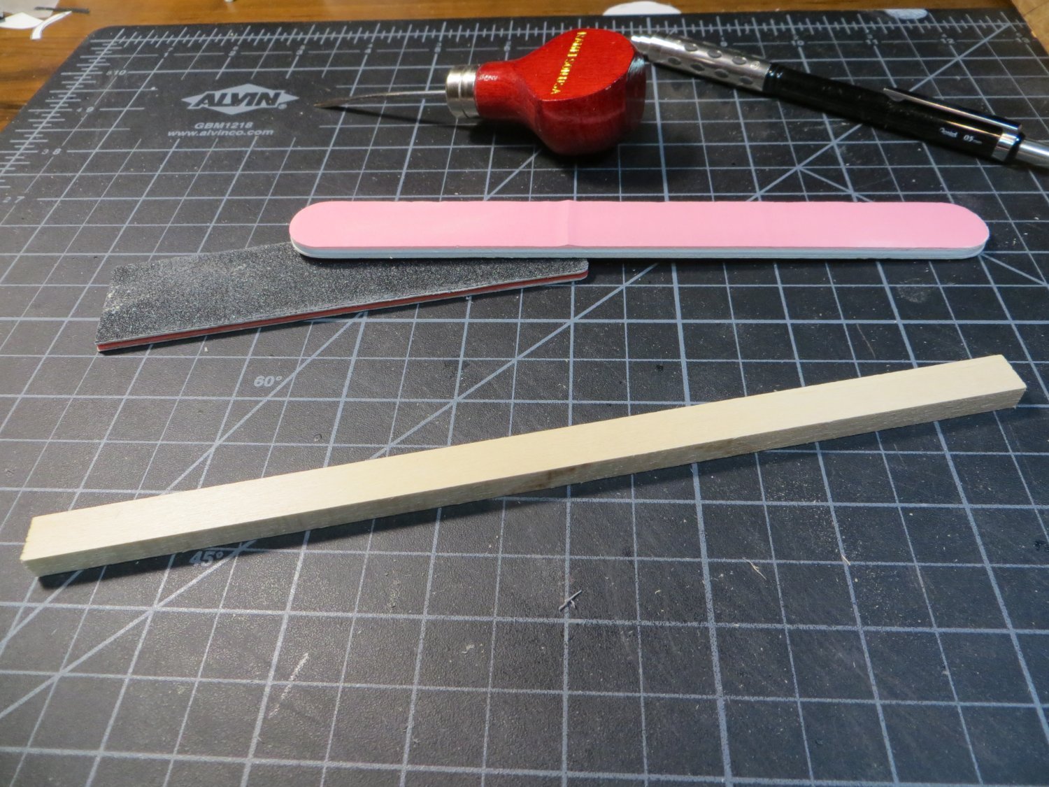
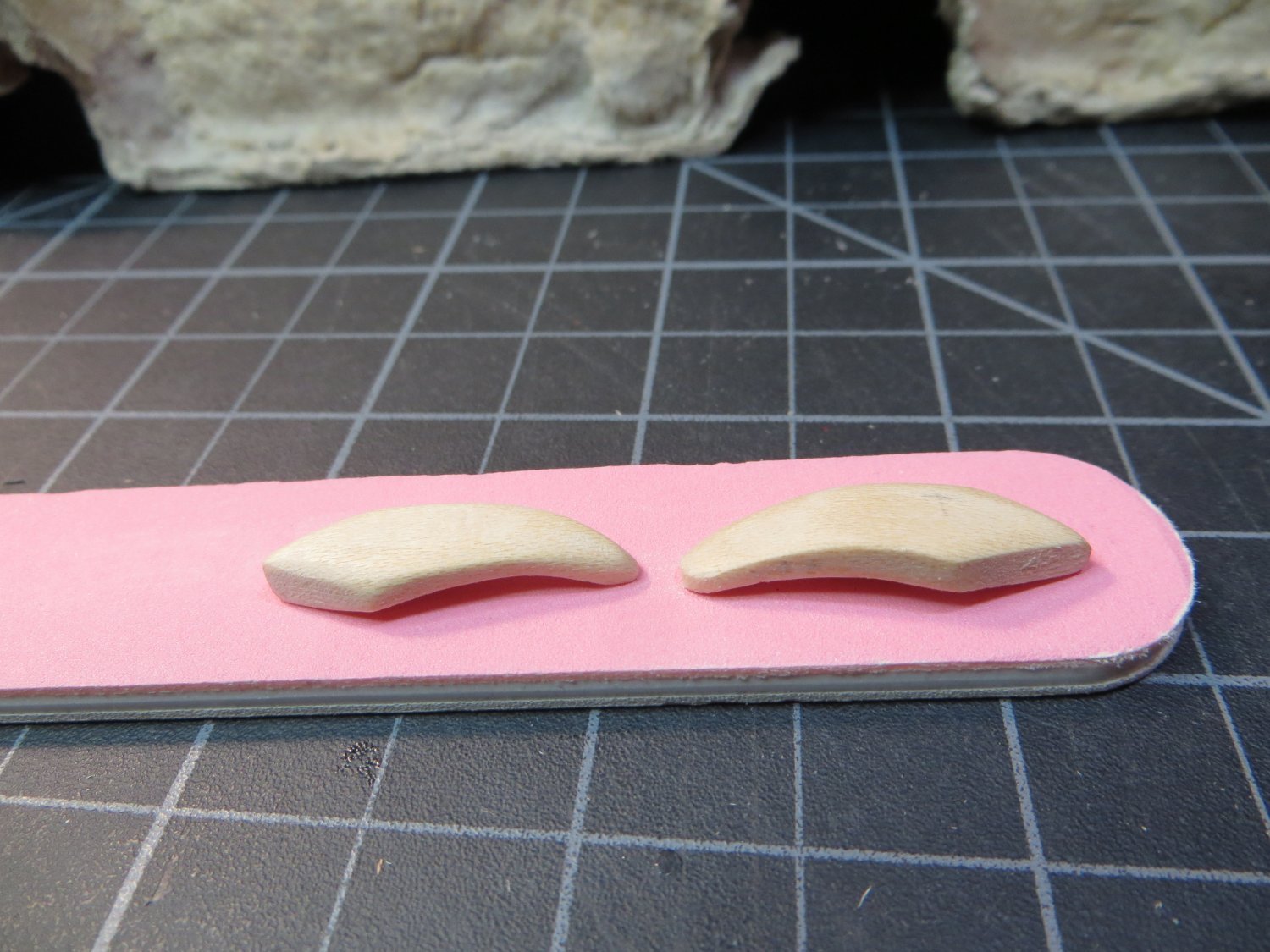
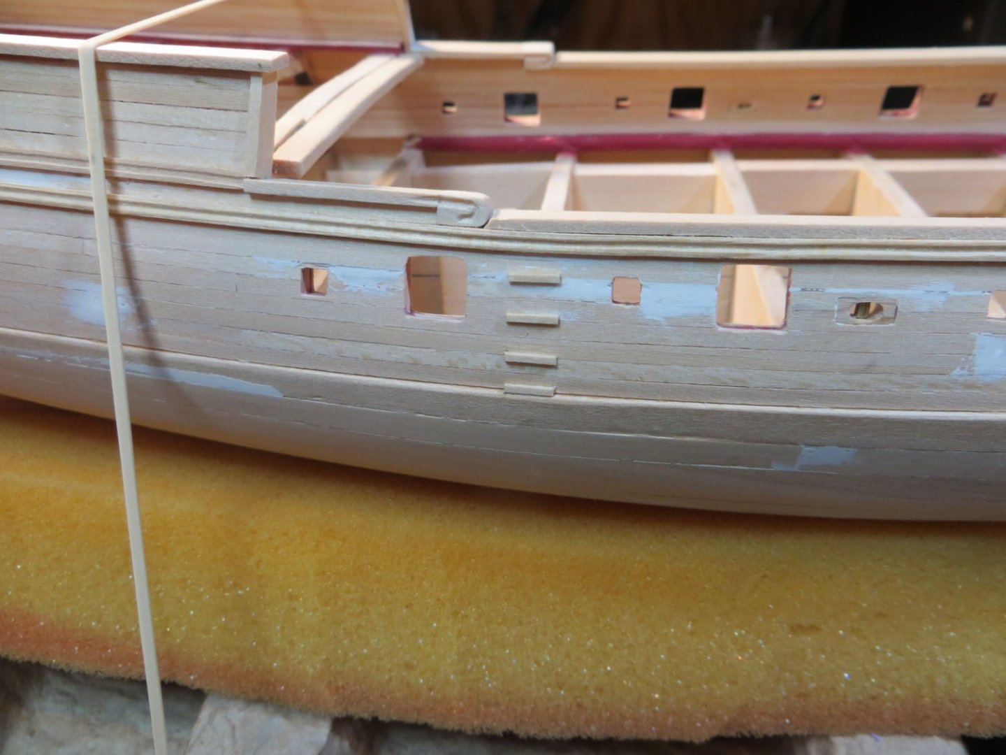
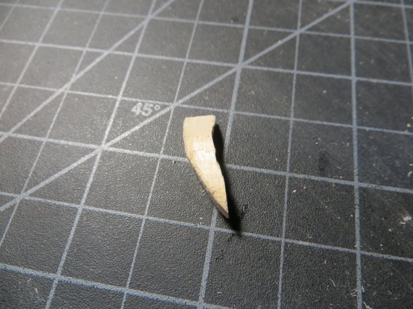
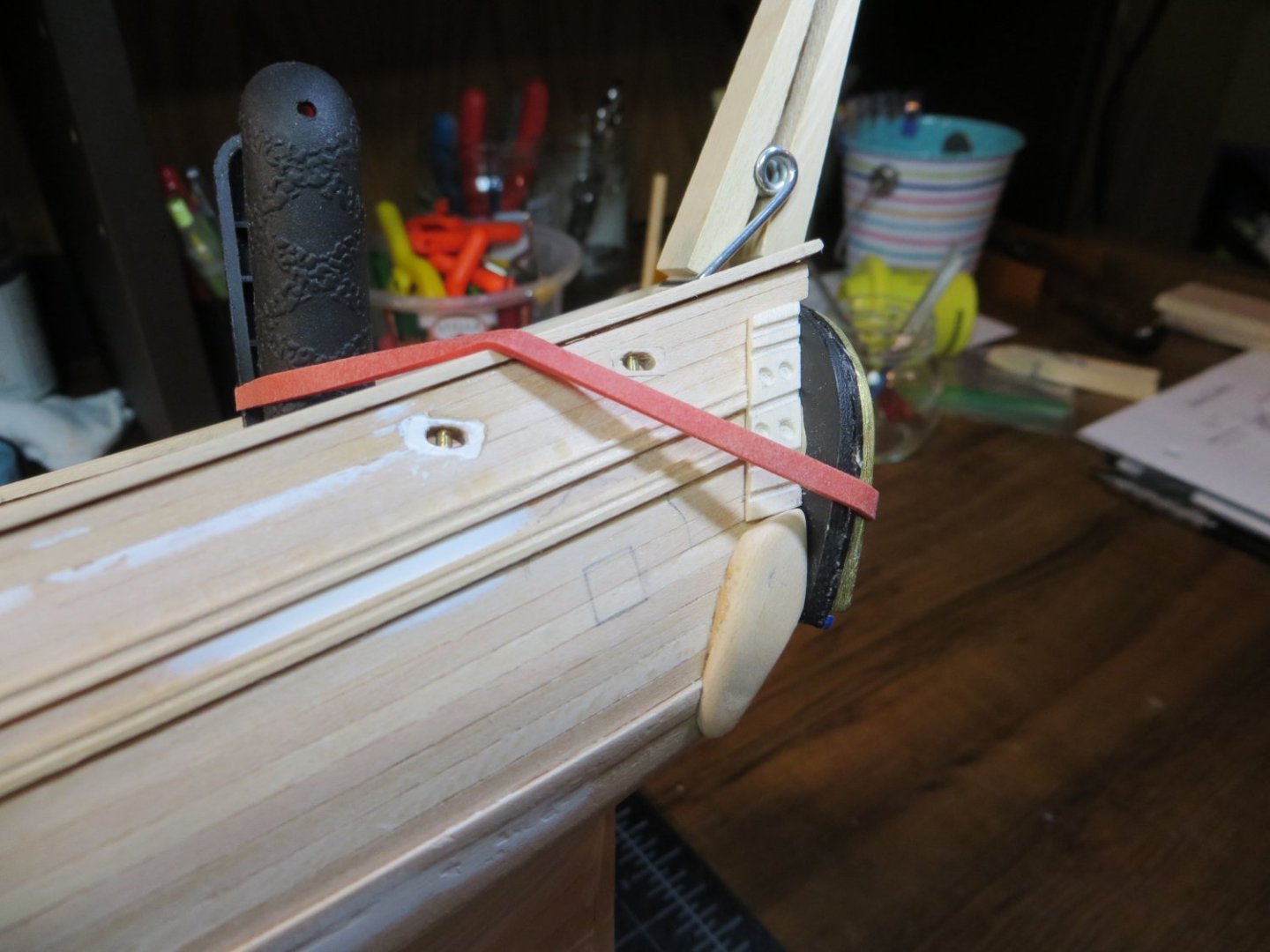
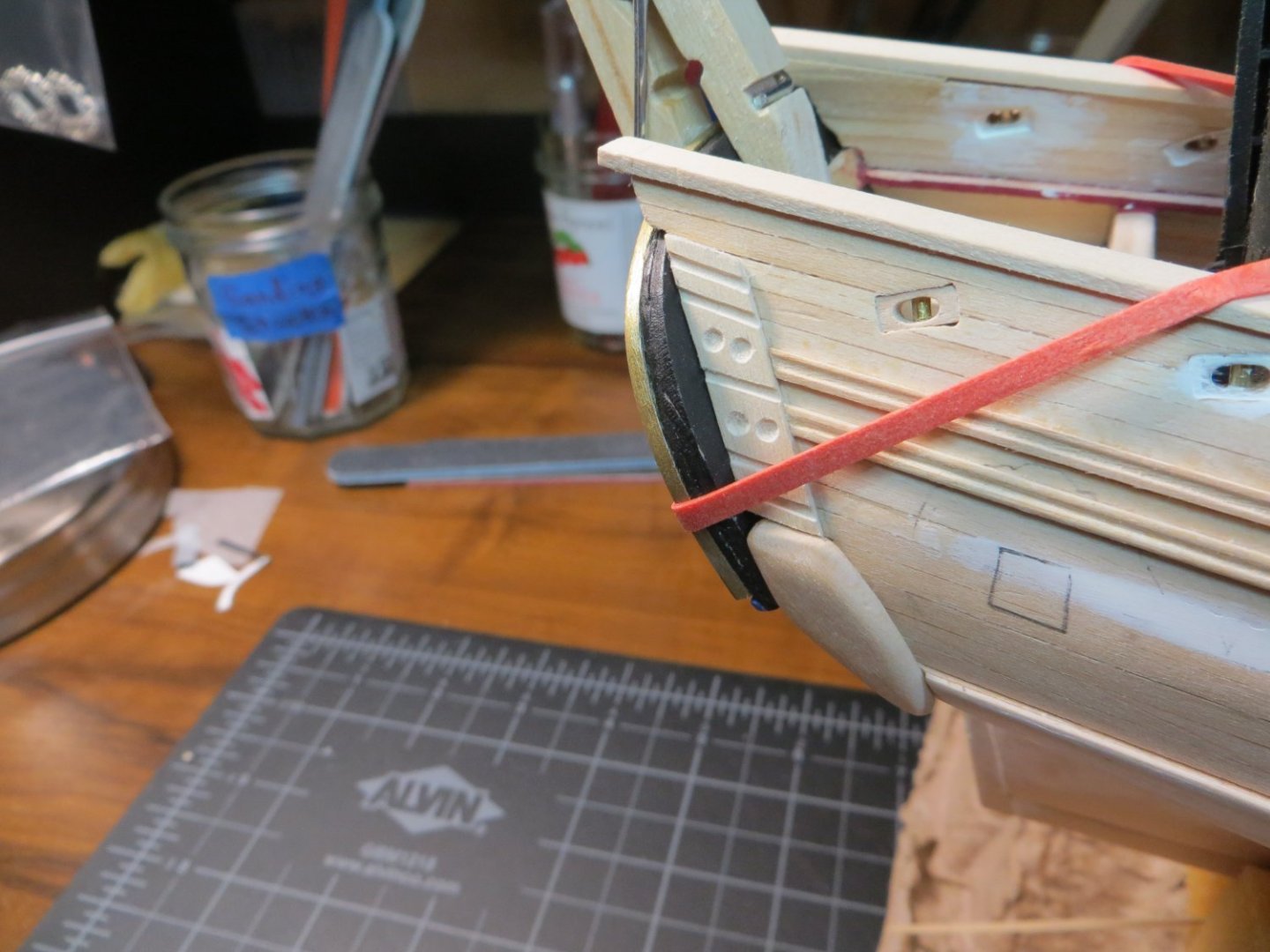
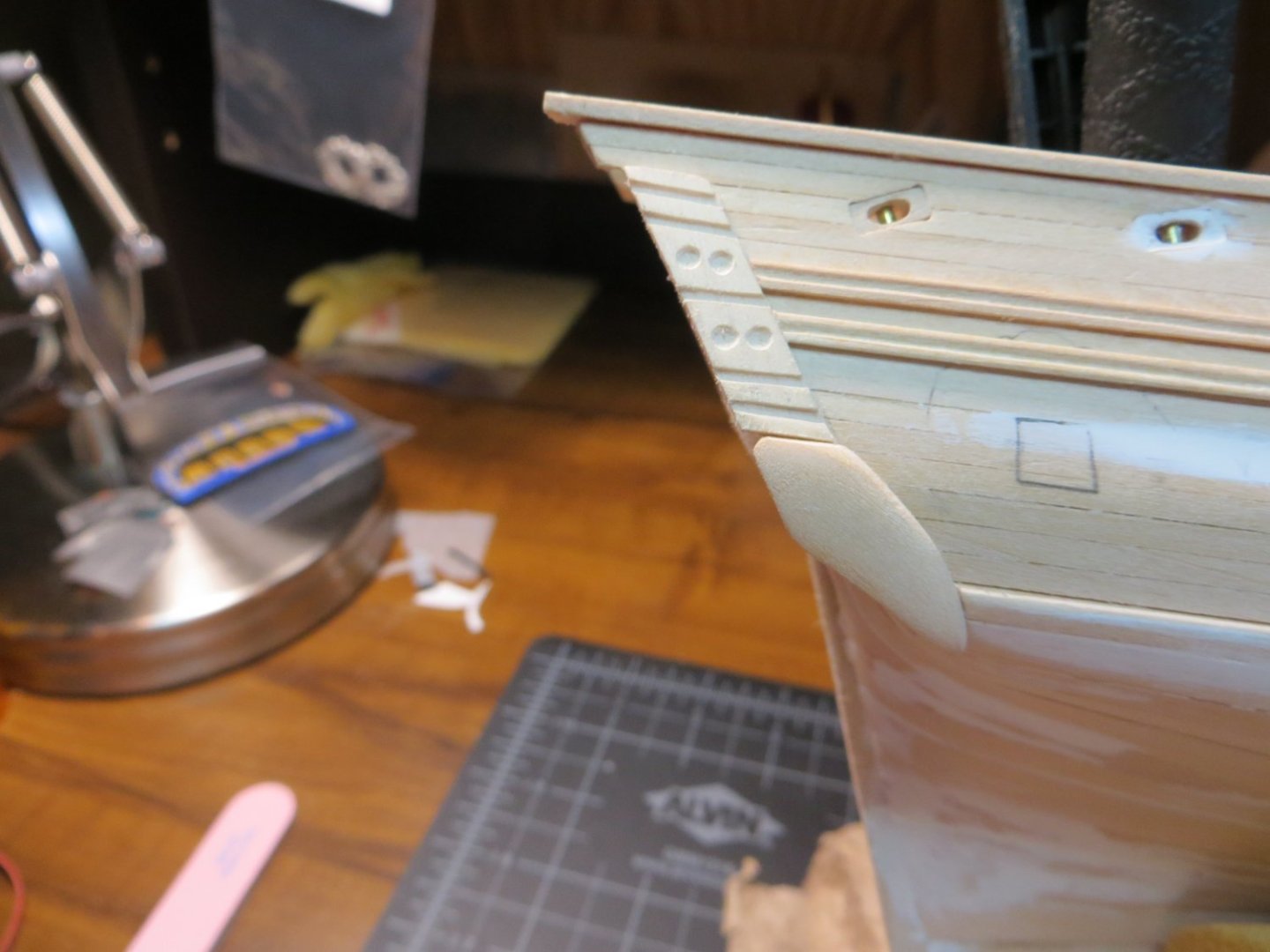
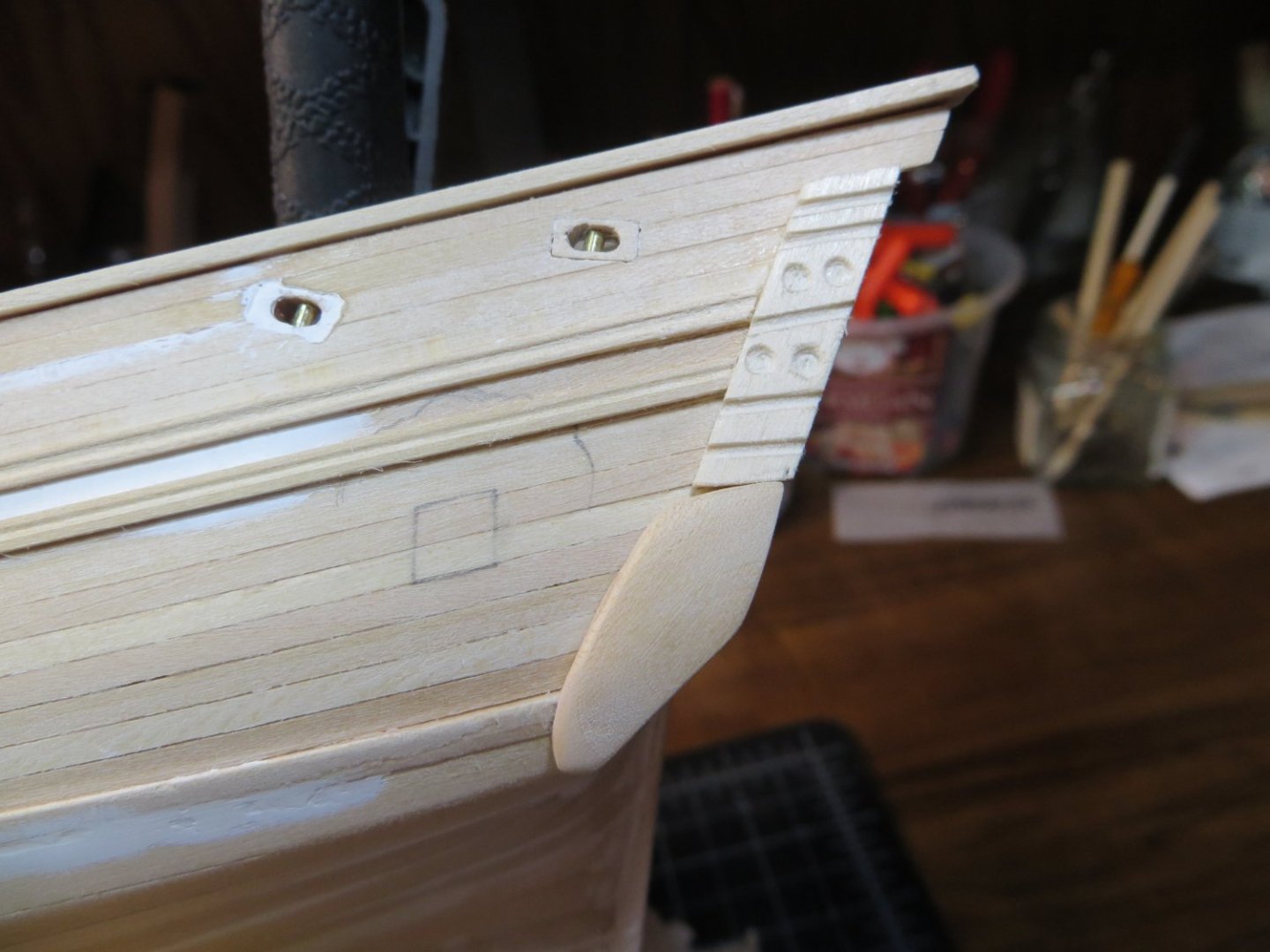
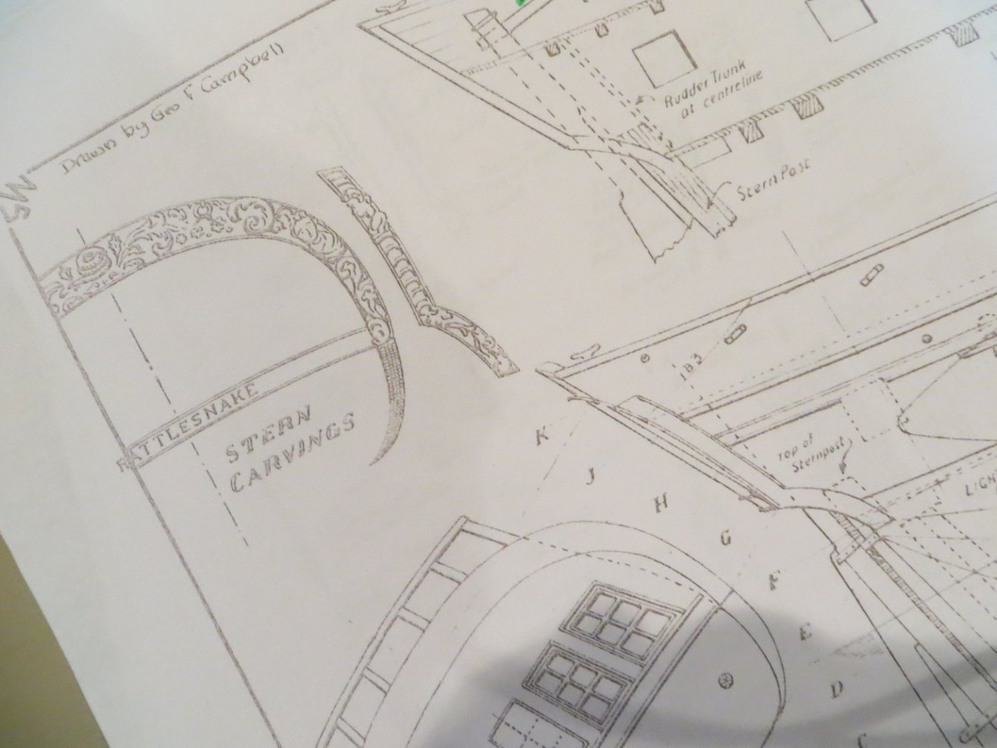
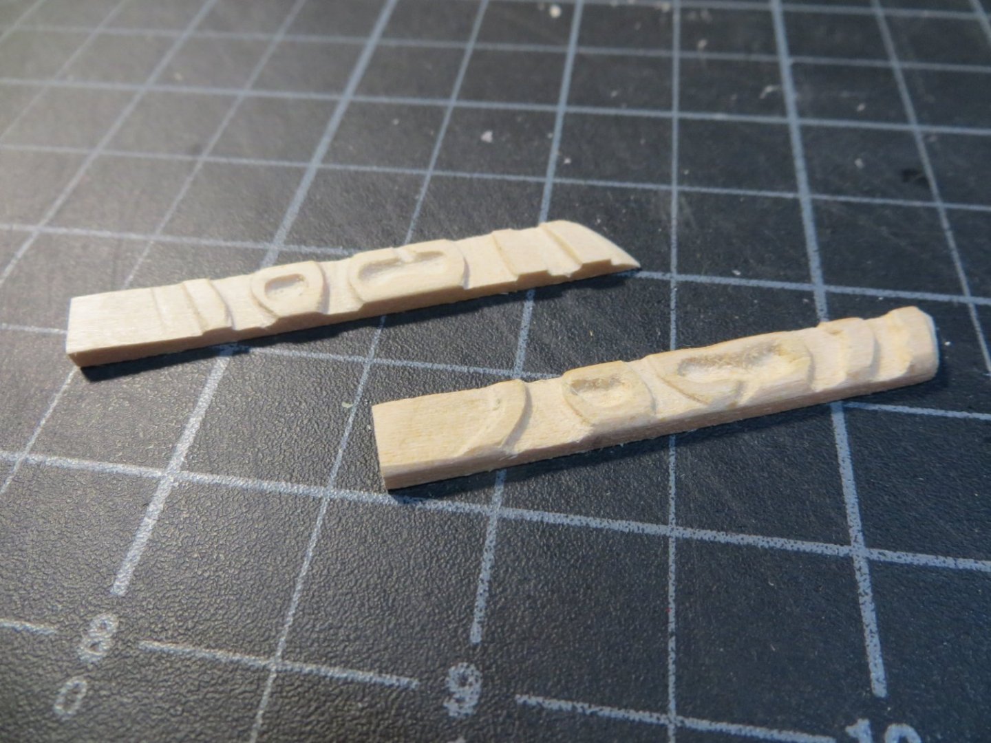
Stage C Hull – Miscellaneous Pieces & Painting Step 31: Carve & Install Counter Timbers & Fashion Pieces I’ve seen a lot of different ways that shipwrights have completed these decorative pieces on the aft hull sides. Allan (Allanyed) said in a post on Dave_E’s log that the upper portion is called the “Counter Timbers” and the lower piece is referred to as the “Fashion Piece” in the instruction manual for Rattlesnake. In the interest of accuracy, I bow to Allan’s expertise on this terminology! Most modelers seem to leave the decorative timbers off. My Bluenose called for a fashion piece in the same position, but I was too much of a newbie to attempt to carve it! I decided I wanted to try my hand at creating these pieces for the Ratt. This is my “interpretation”. Here are the pieces in question from the prints… I started with the Fashion Pieces. The difficult part of this is that the piece curves on two different planes. You have to select a piece of strip wood that is wide enough in both directions to take the widest part of the curve on each side. I selected one of the wood strips from a bundle of basswood that I purchased some time ago that is 3/8 x ¼”. I started out by creating a template off the plans and marked up the wood strip. My first effort was just horrible! Here is a pic for your laugh of the day… But this first attempt taught me a few things. And I kept at it until I made something that resembled what I’ve seen in a few different build logs. The next step was to create the Counter Timbers. I tried to carve something that looked like the piece in the blueprint plans. I quickly realized this was beyond my skill. I think I used too thick of a piece of stripwood and there was too much open space between the carvings. I spent a lot of hours on this and then decided to add them to the scrap pile! I used a thinner piece of stripwood and made a simpler design to represent my interpretation of the decorative counter timber. I put the transom in position temporarily to get the 4 carved pieces to fit snuggly up against it. After gluing the pieces in place, I decided the fashion pieces still looked a little too thick & heavy. I sanded them down a lot more. They actually look slimmer to the eye than they look in the pics below. I have one more step before airbrushing primer over the entire hull. I need to add the stair steps on the outside of the hull. These are shown in the plans. Question: Does anyone know if these steps need to be installed on both sides of the hull or just the starboard? As always, I appreciate any feedback you may have. Thanks, Ed


-
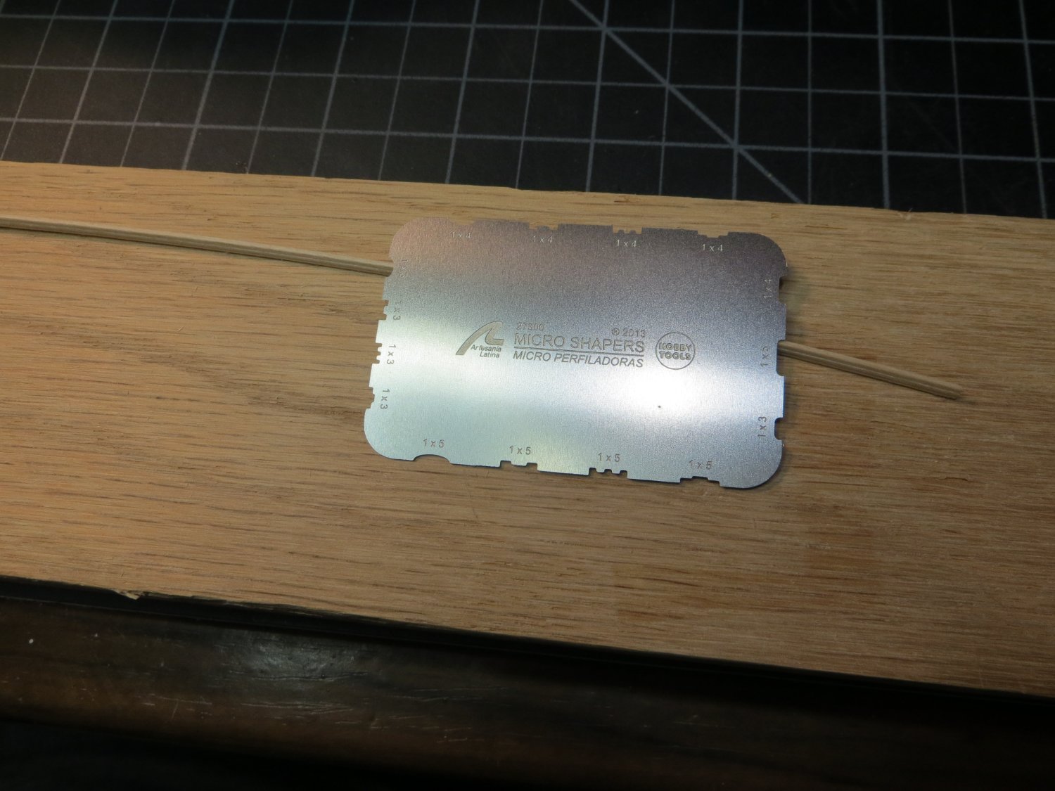
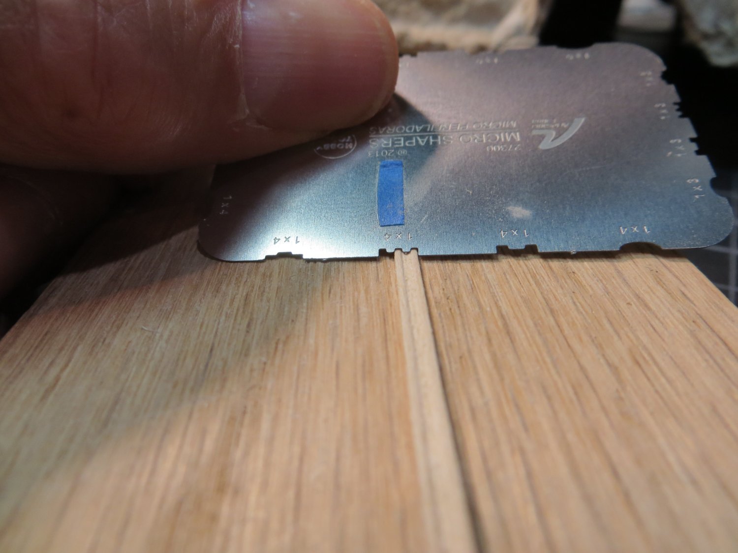
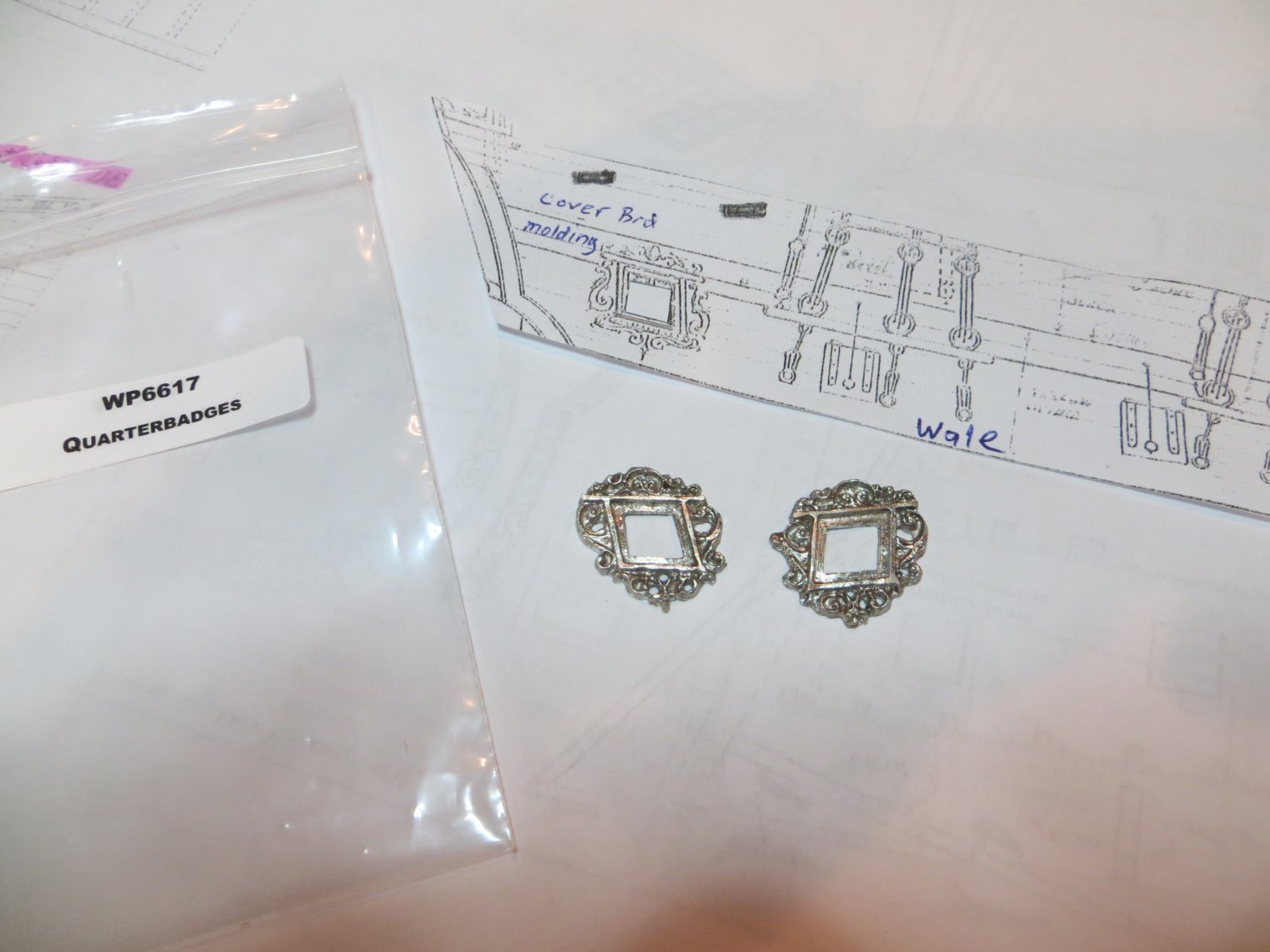
I haven’t posted any progress in a while. Not as much ship time. Summer activities take over this time of year! I have been working on the molding strips and fashion pieces. I spent a lot of time trying to carve wood for these! The scrap bin is over-flowing!! Step 29: Clean & Fit Quarterbadges Before I installed the hull molding & covering strips, I figured I should determine the location of the Quarterbadges. I cleaned up the Britannia metal pieces provided in the kit using files and carving burrs in the Dremel. The final step was to clean them in an ultrasonic jewelry bath to remove any tarnish and oil residue. I used a copy of the quarterdeck plans, clothes pinned to the ship, to locate the position for these pieces on the port & starboard sides. I made a pencil outline on the hull. I intend to install the full length of the molding strips and then cut away the section where the Quarterbadges will be attached later. This is as far as I went with these at this time. Step 30: Install Hull Molding & Covering Strips There are two thin wood strips that serve as decorative molding on both sides of the ship. The Molding Strip runs the entire length of the ship. It fits just under the overhang of the main deck rail at midship. It extends forward 1 strake below the focsl railing and aft along the quarter deck hull to the transom. The Covering strip is only found on the quarter deck, 1 strake above the molding strip. Both strips have a decorative shape carved into them. The full-length molding strip is supposed to have an extended outside ridge in the center. The Covering strip has a U-shaped inside cut carved into the center. I bought the Artesenia metal scrappers to make these cuts. Unfortunately, they use metric measure and the kit wood is in US fractional measurement. So, some “improvisation” is required to achieve the desired result. I did the molding strip first. I tried using a half of one of the shapes and scrapped each side by flipping the strip. The “outie” cut turned out kind of narrow. I glued it on anyway and moved on to the covering strip. I was able to make a nice clean cut for the covering strip U-shape. As soon as I glued this strip on the rear Q-deck, I was unhappy with the way the molding strip looked by comparison. Eventually, I ripped the molding strip off and replaced it with another U-shaped strip that was the same as the covering board. Not what the plan calls for, but I like the way it looks much better! Here are some pictures. Artesania Scrapper & 1/32” x 3/32” Stripwood Close-up of how I used the scrapper to cut the center groove, one side at a time. Improvisation! The finished molding and covering strips glued in place on the hull I completed the Counter Timbers and Fashion Pieces today and I will make a separate post for them soon. Thanks, Ed