HOLIDAY DONATION DRIVE - SUPPORT MSW - DO YOUR PART TO KEEP THIS GREAT FORUM GOING! (Only 20 donations so far - C'mon guys!)
×

Ed Ku20
-
Posts
230 -
Joined
-
Last visited
Content Type
Profiles
Forums
Gallery
Events
Everything posted by Ed Ku20
-
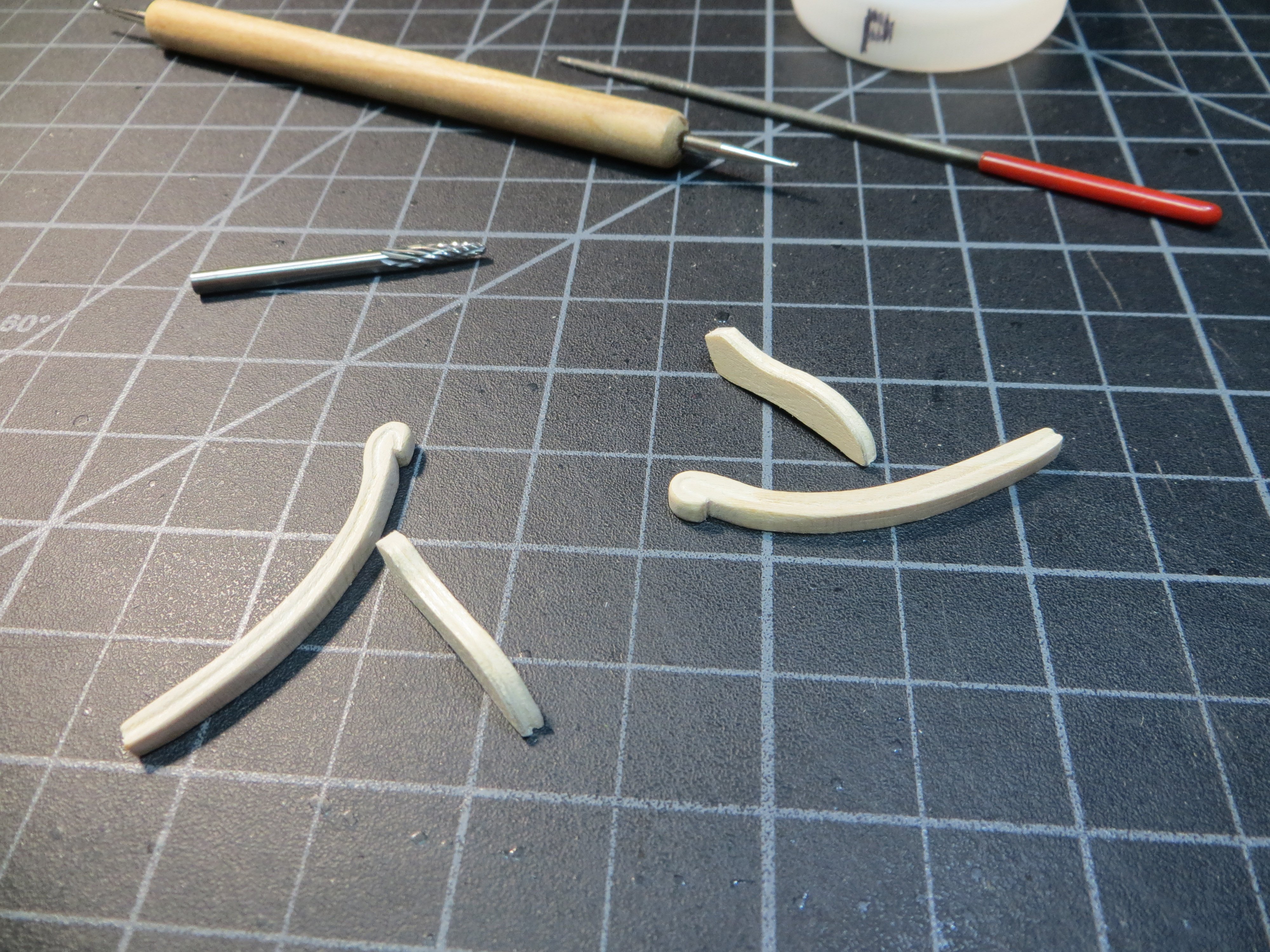
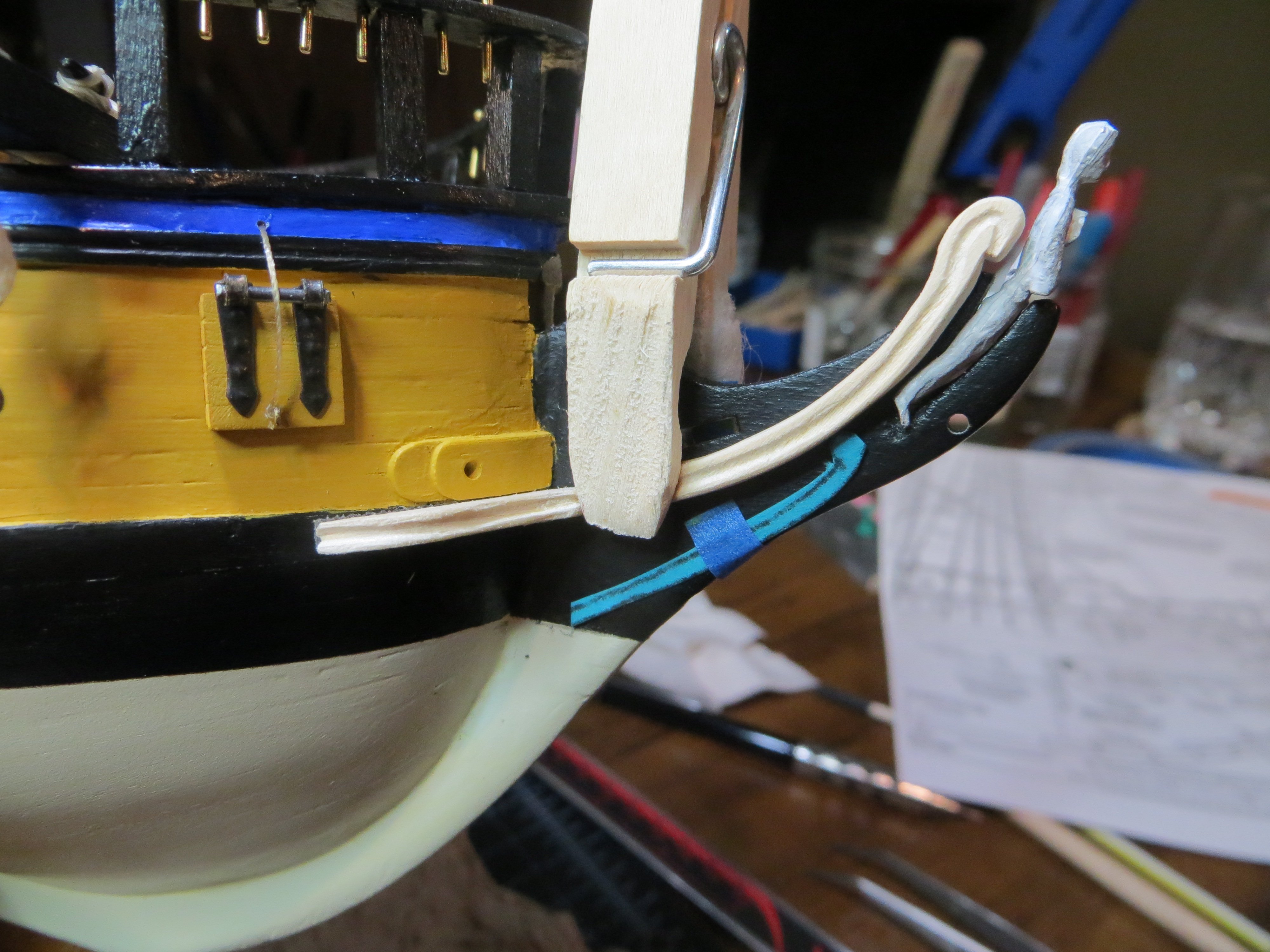
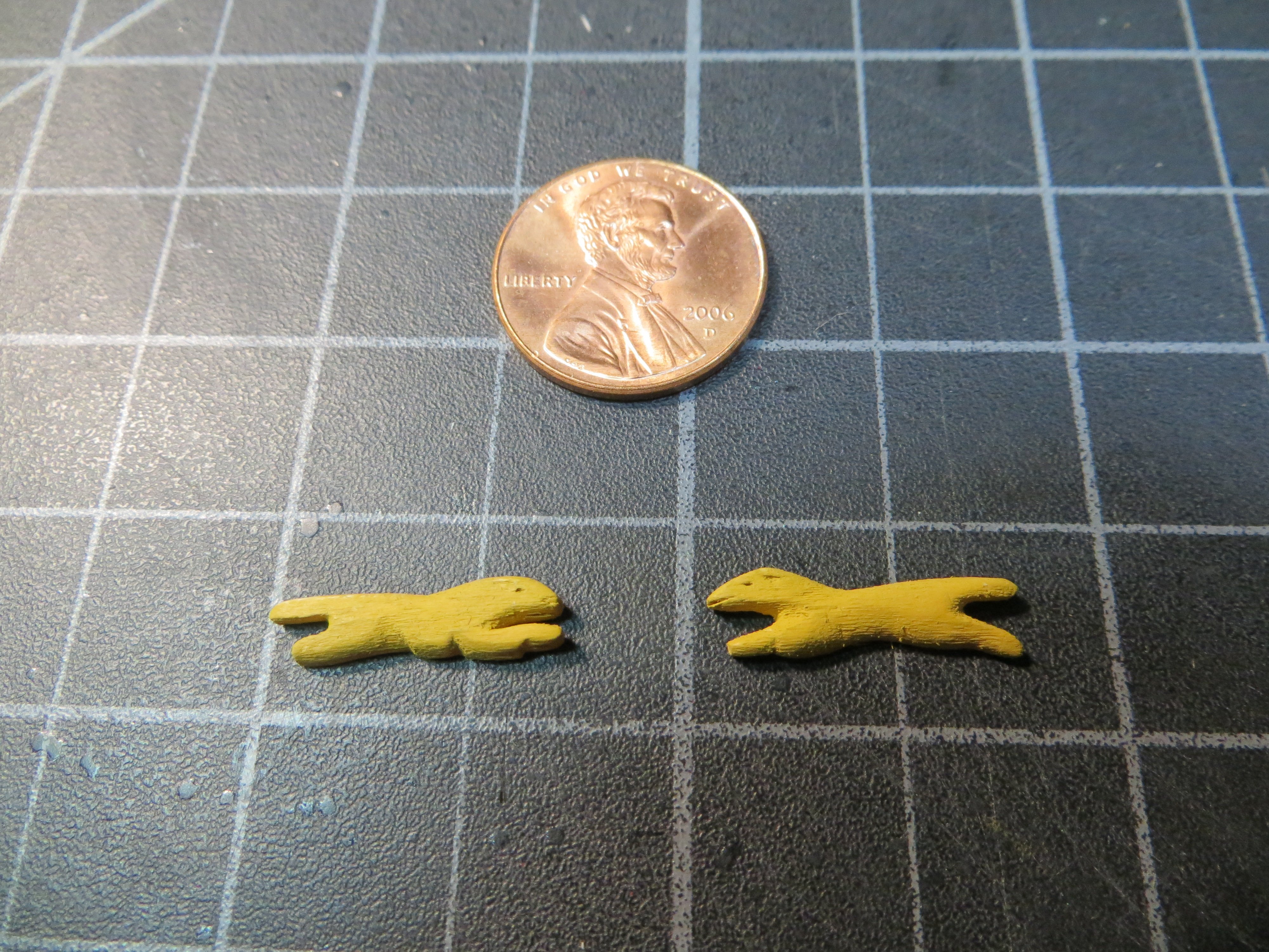
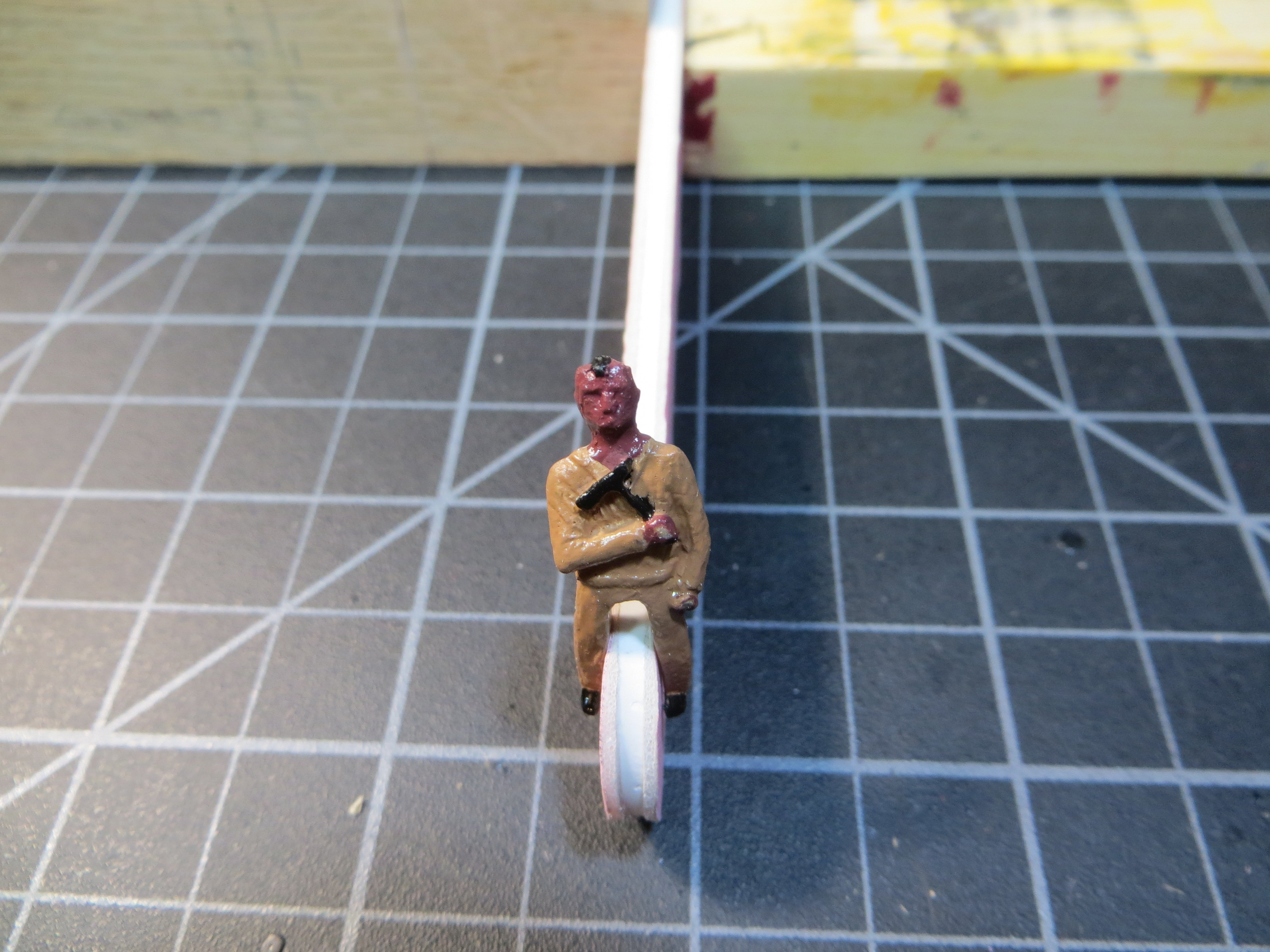
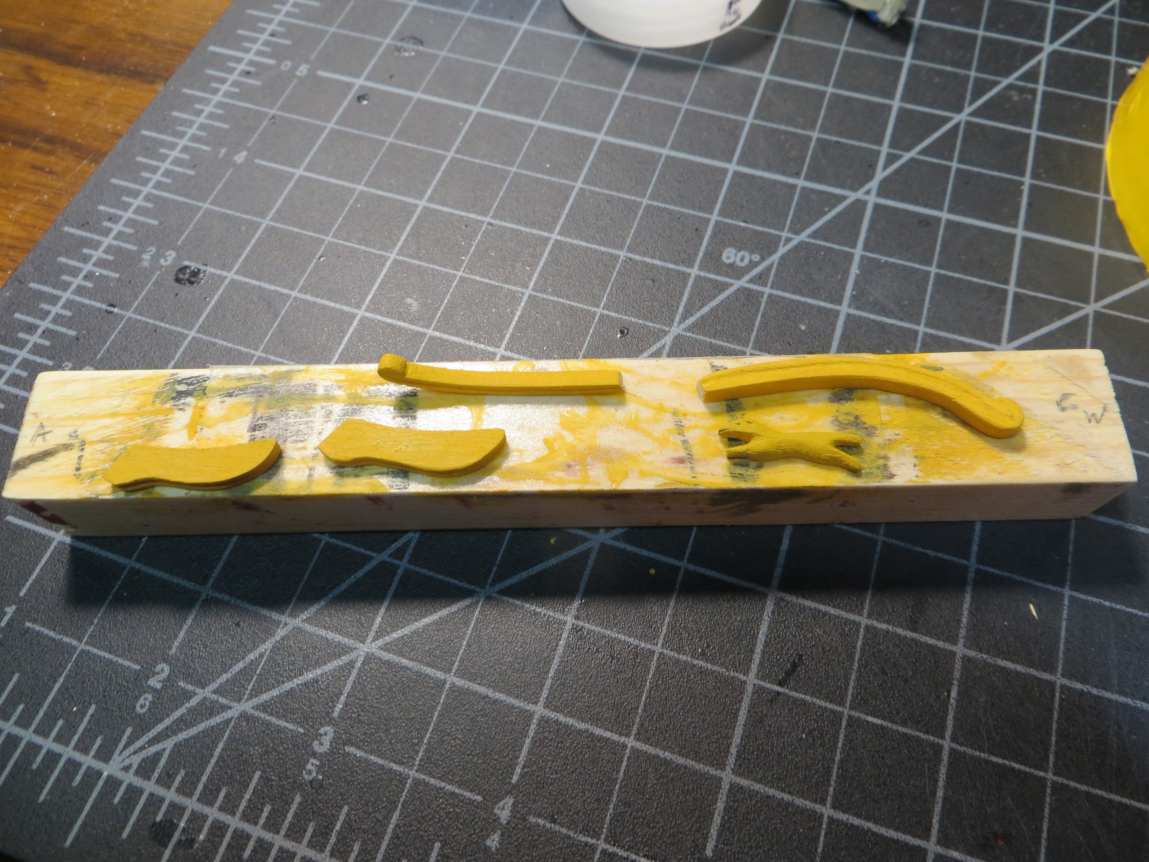
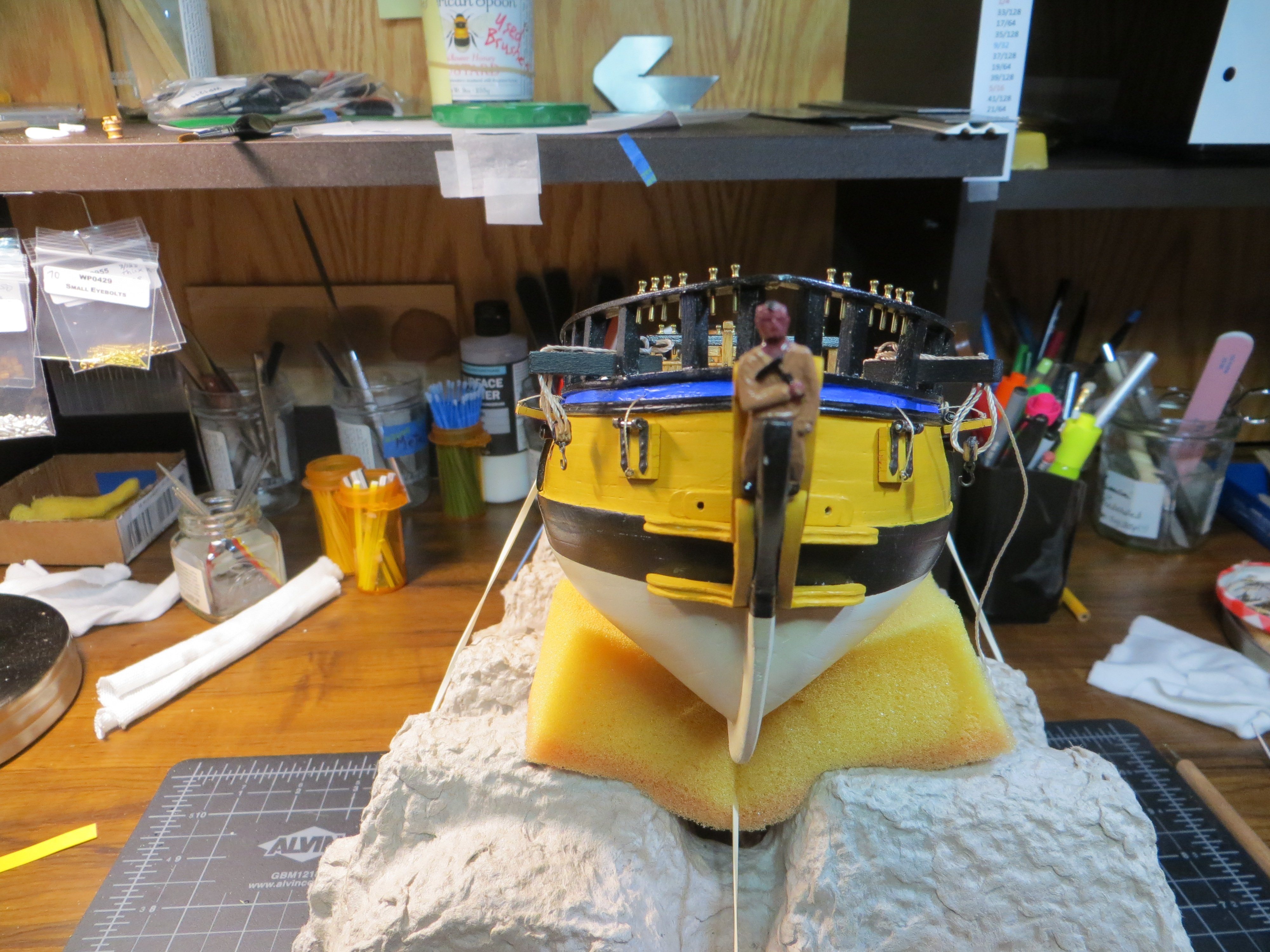
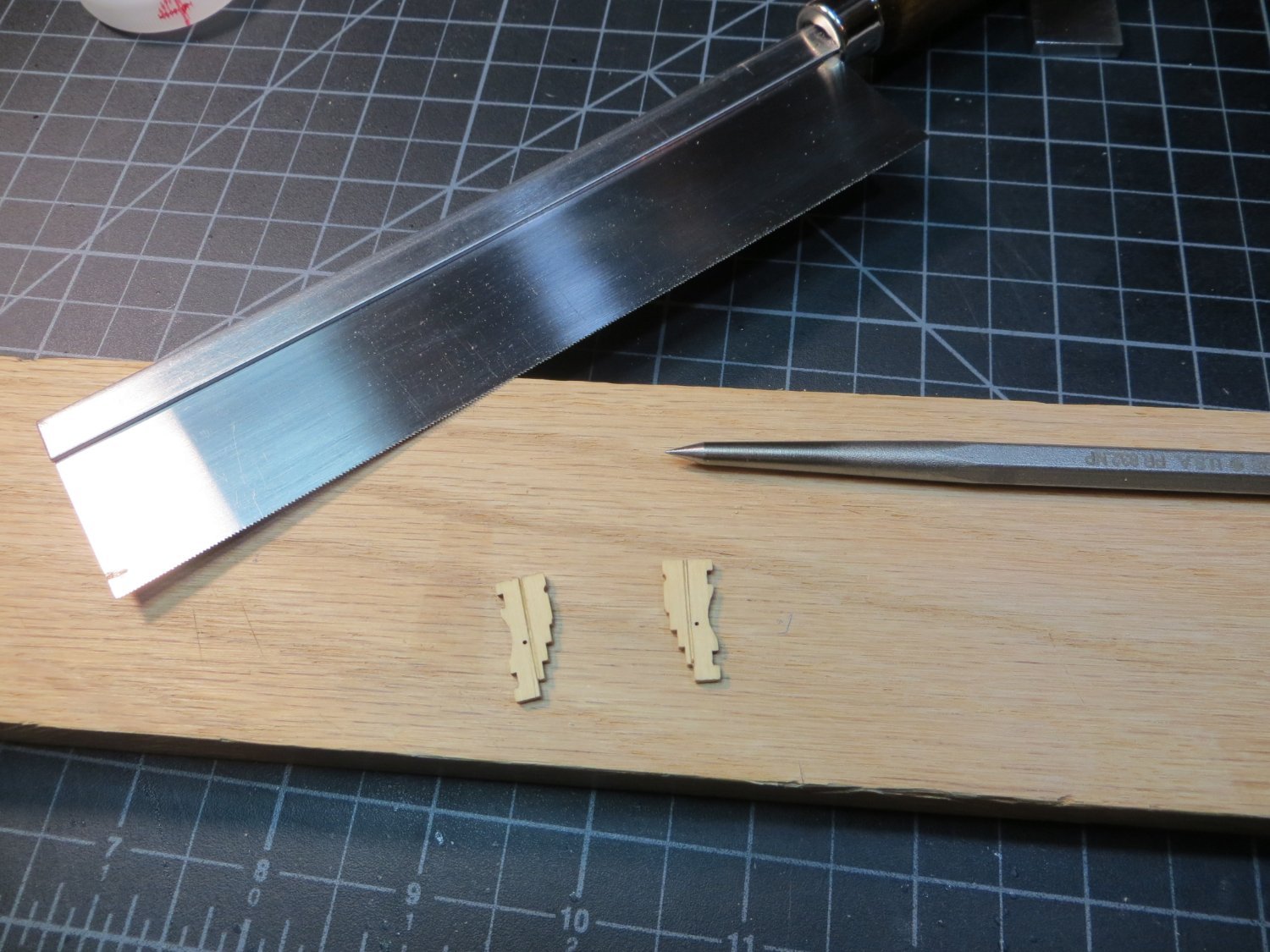
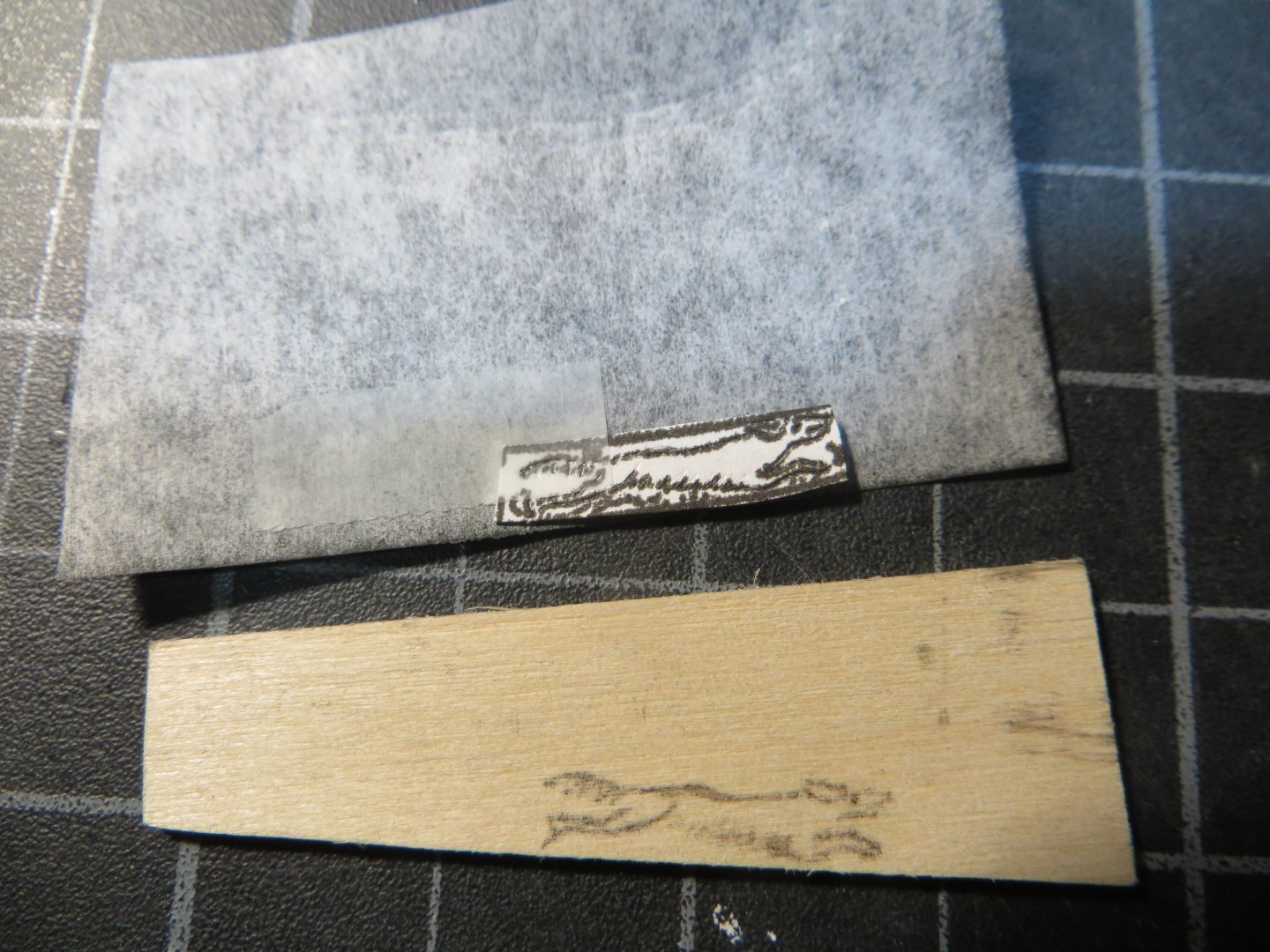
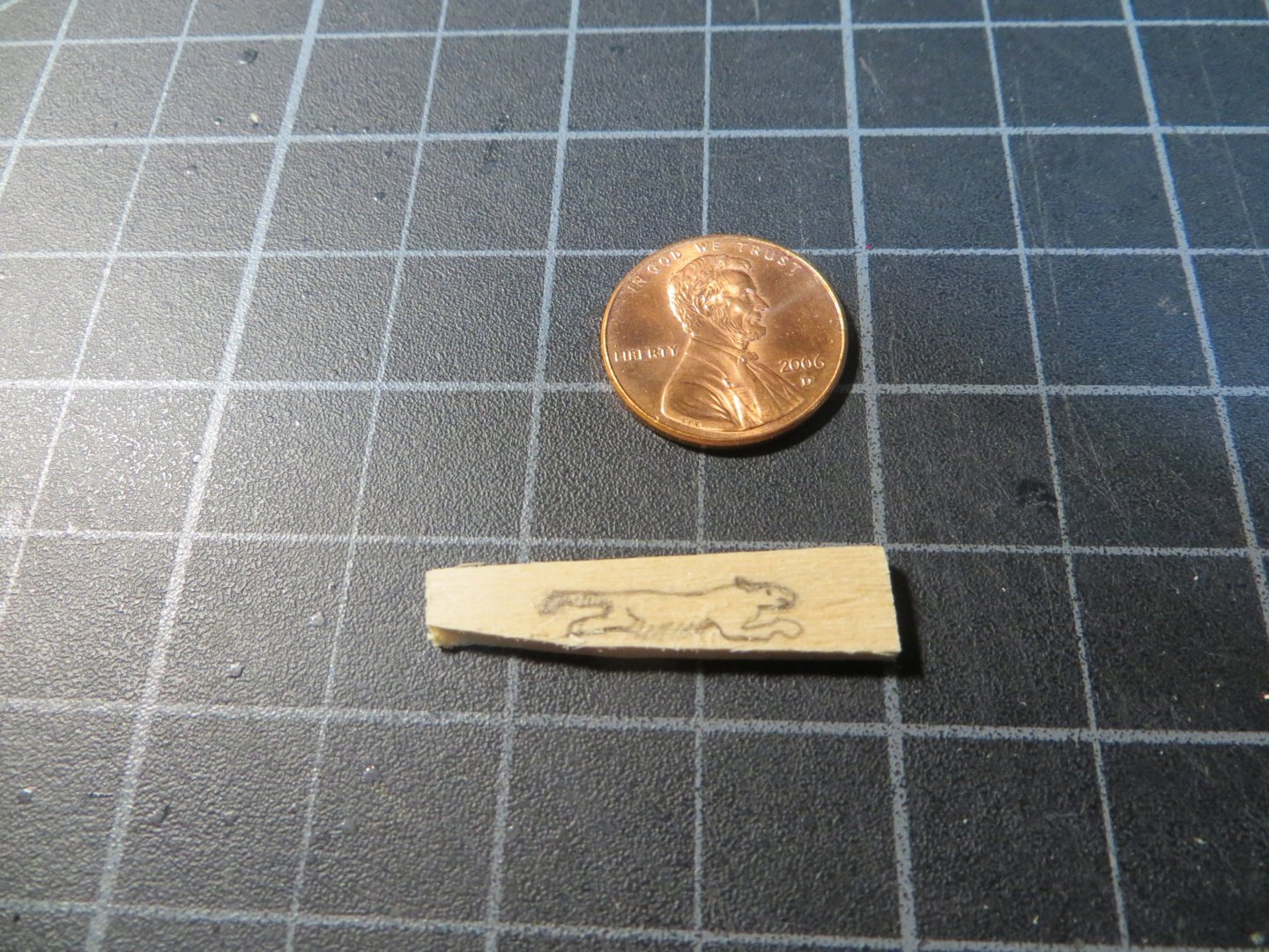
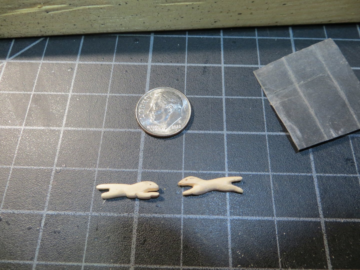
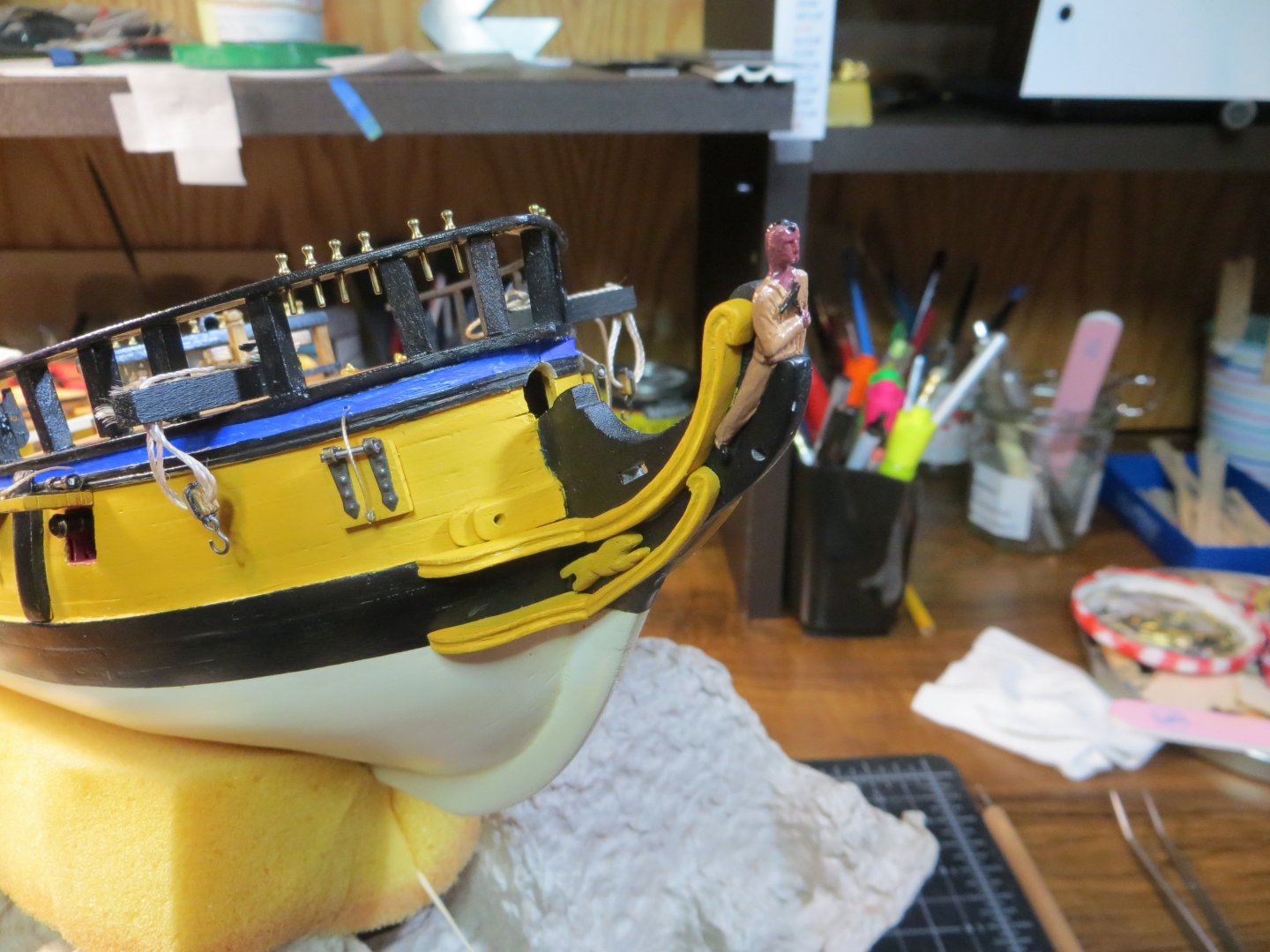
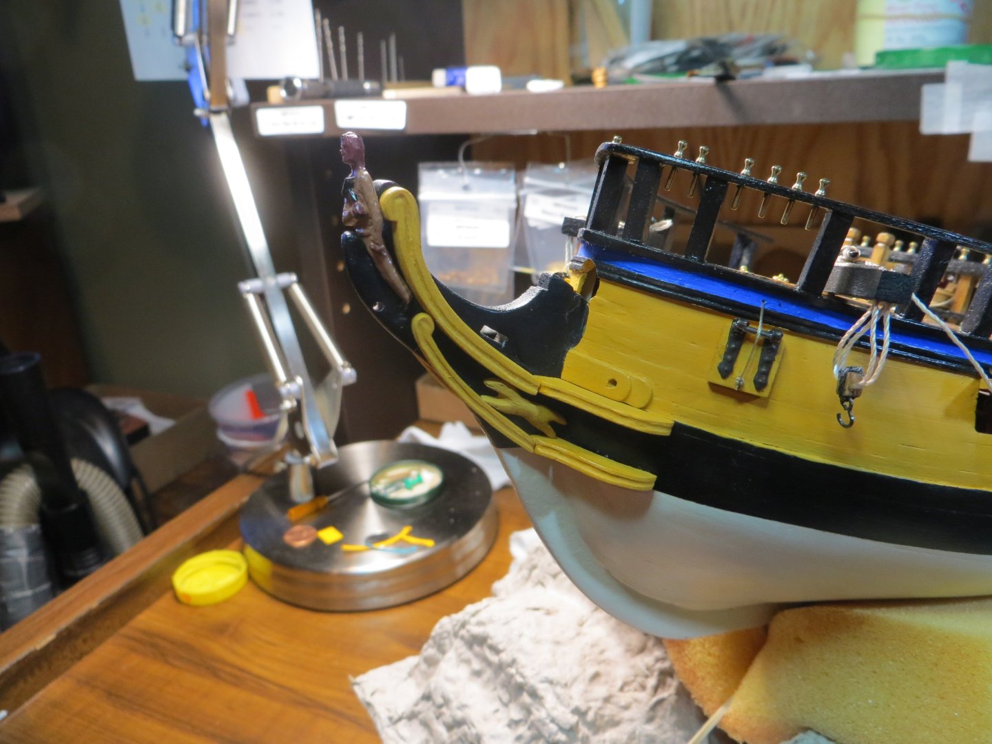
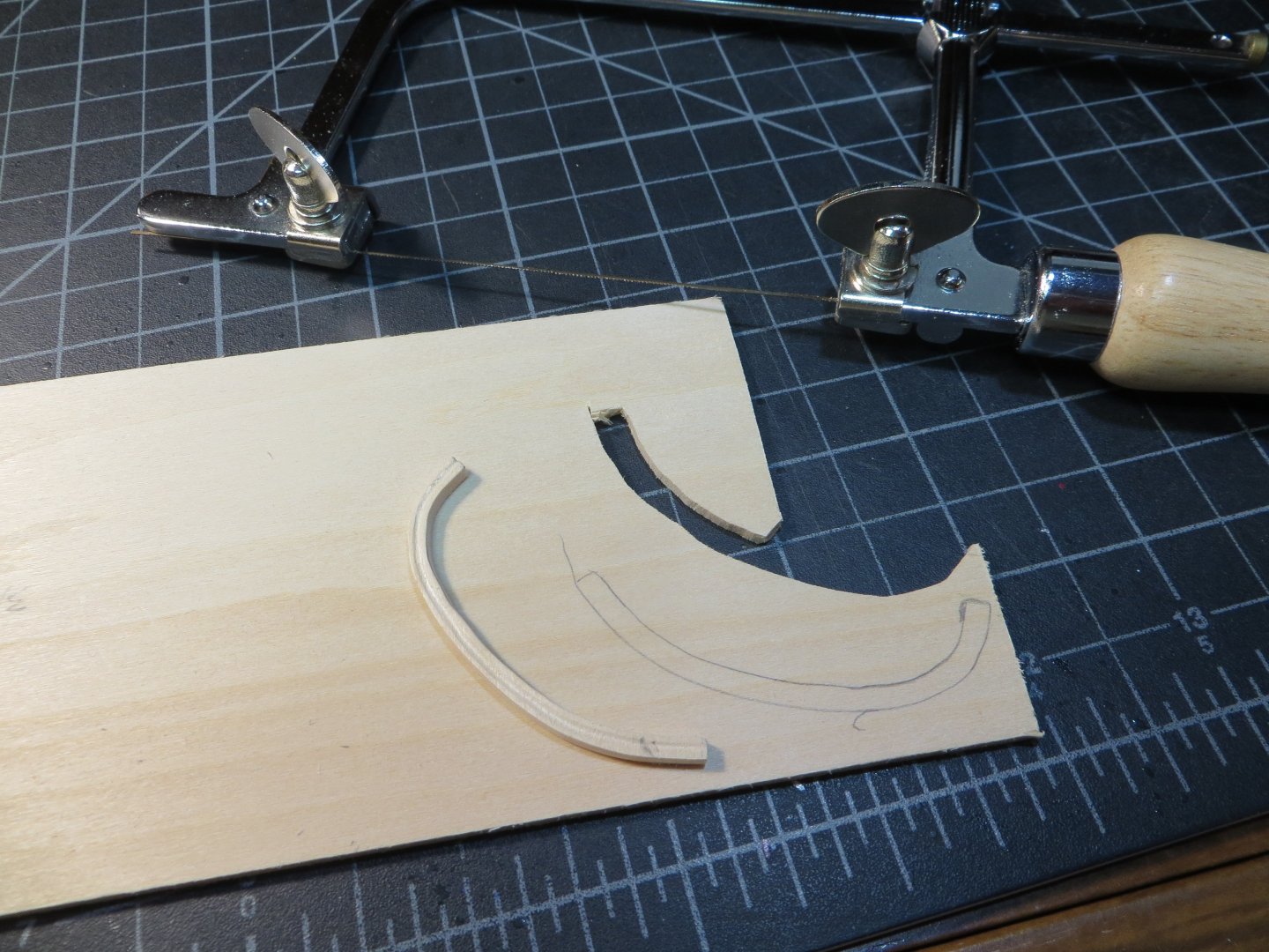
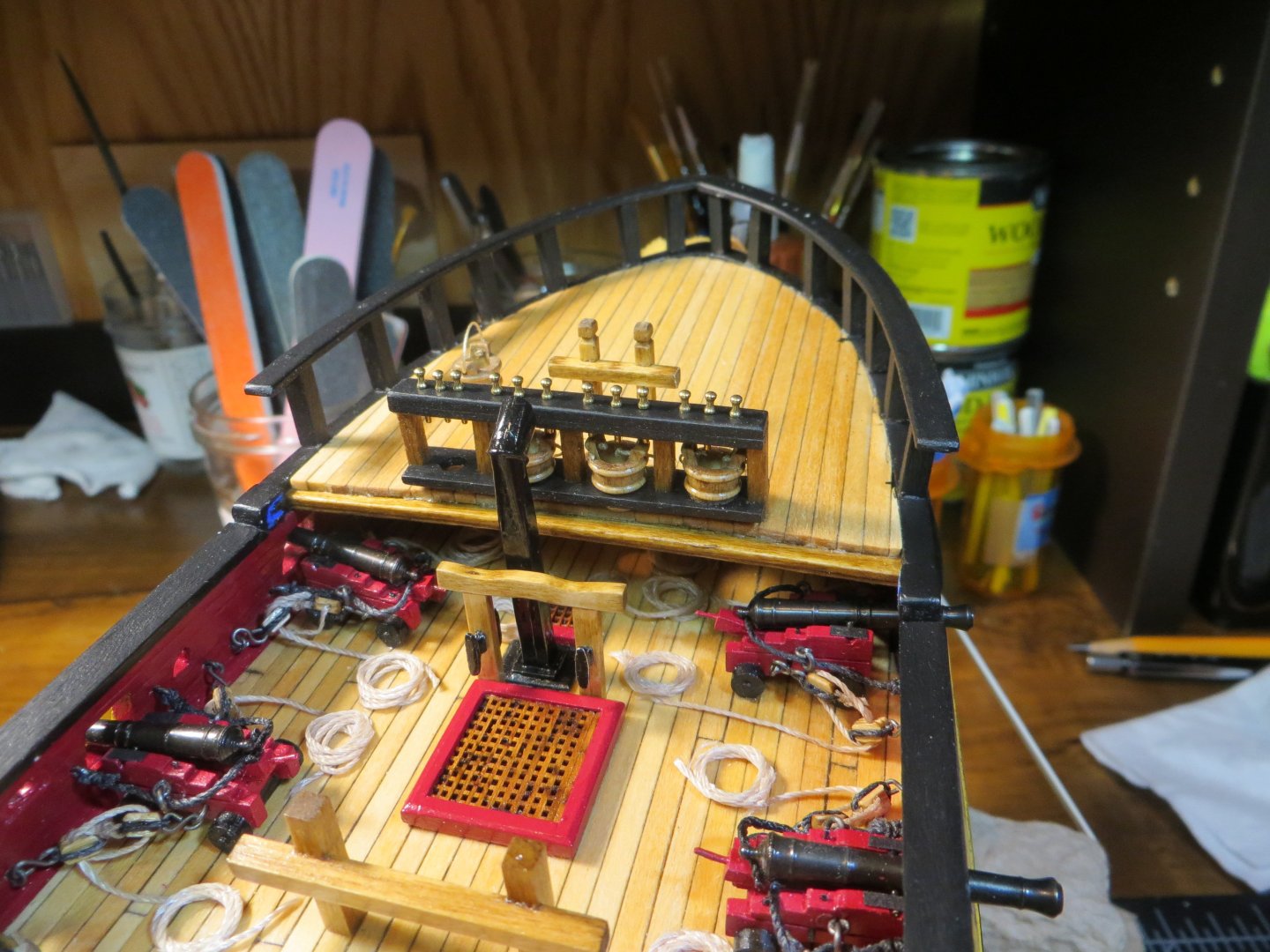
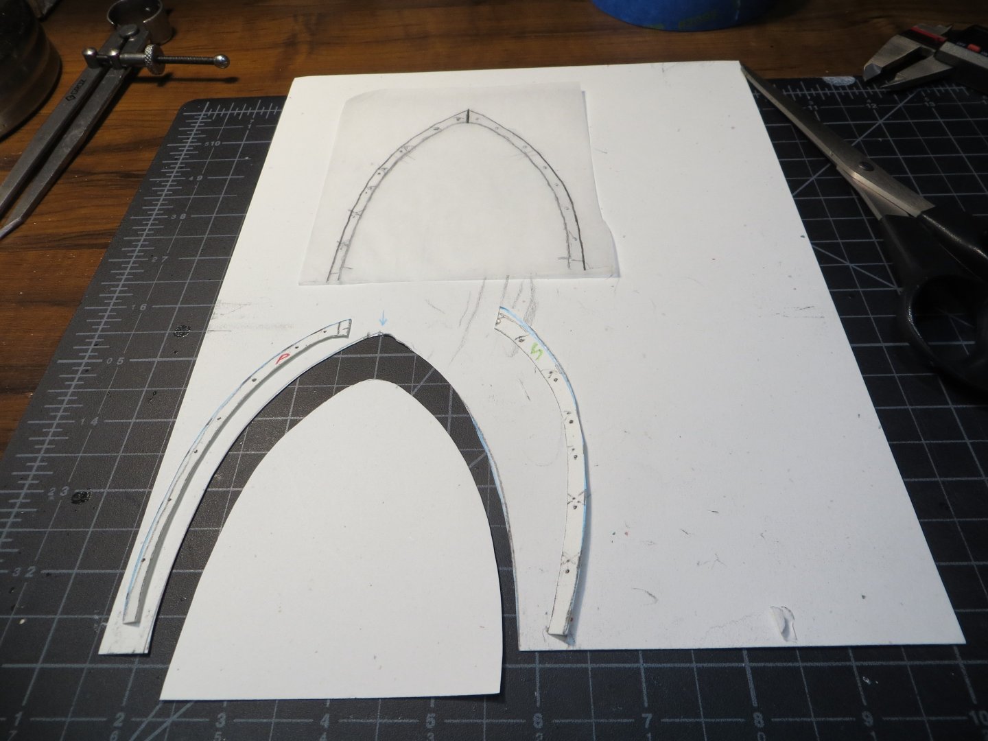
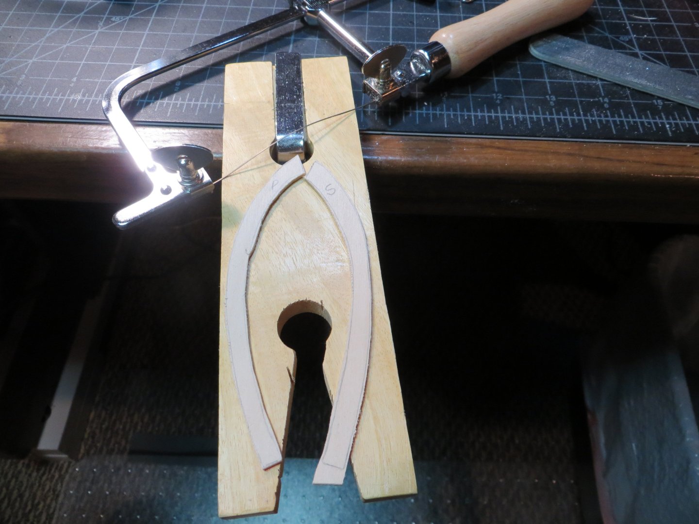
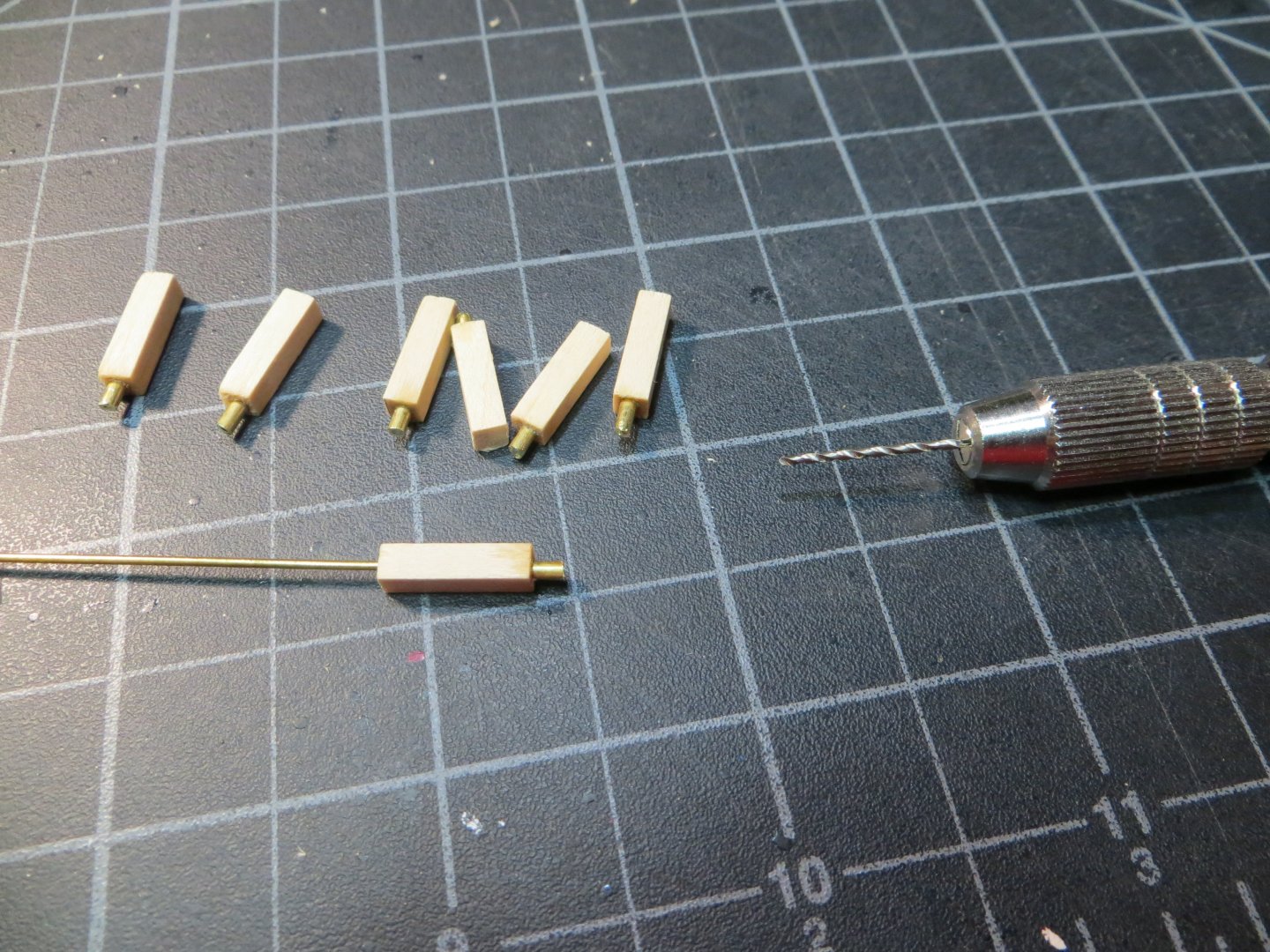
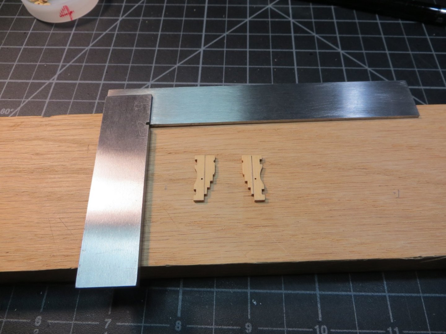
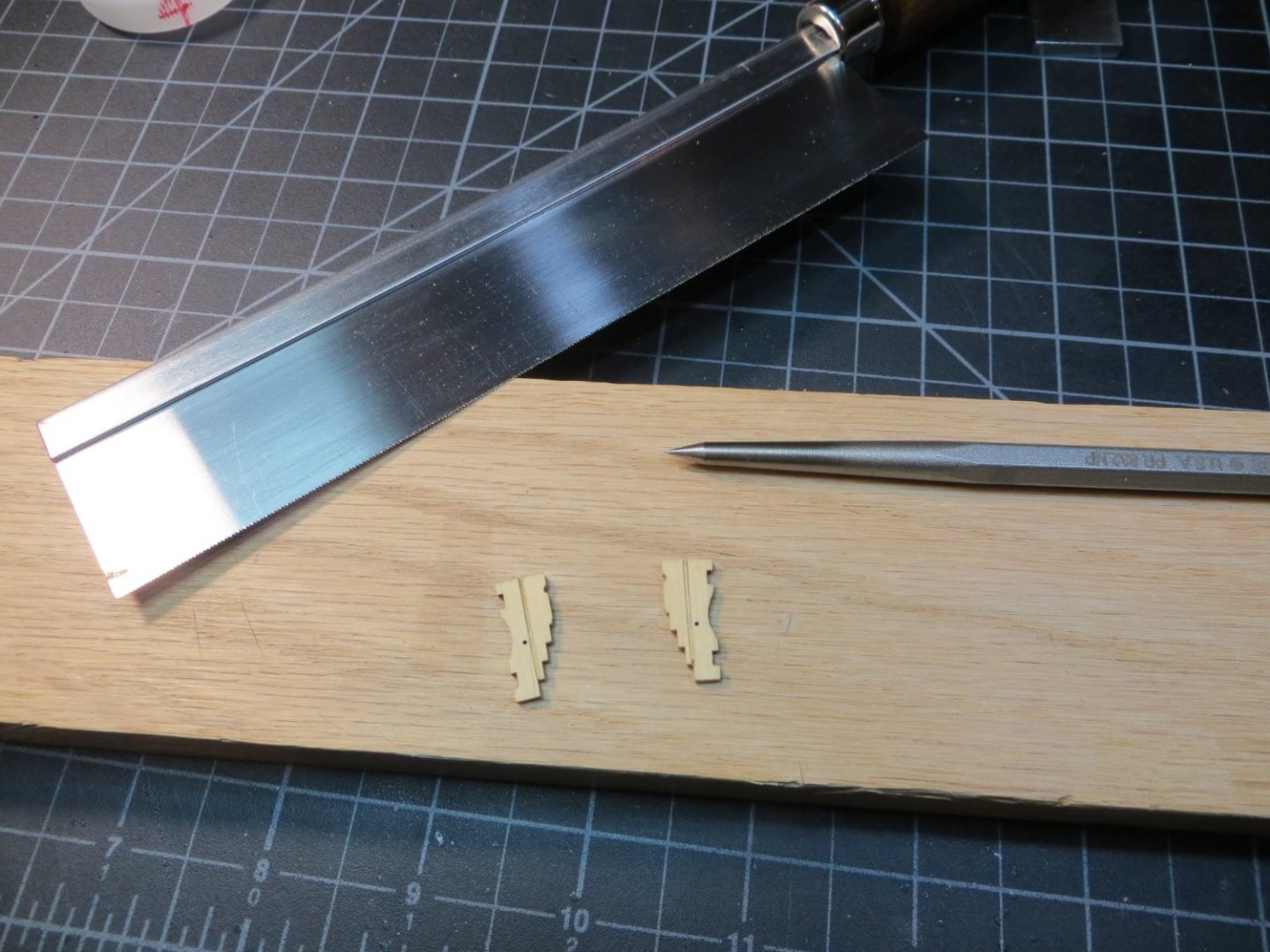
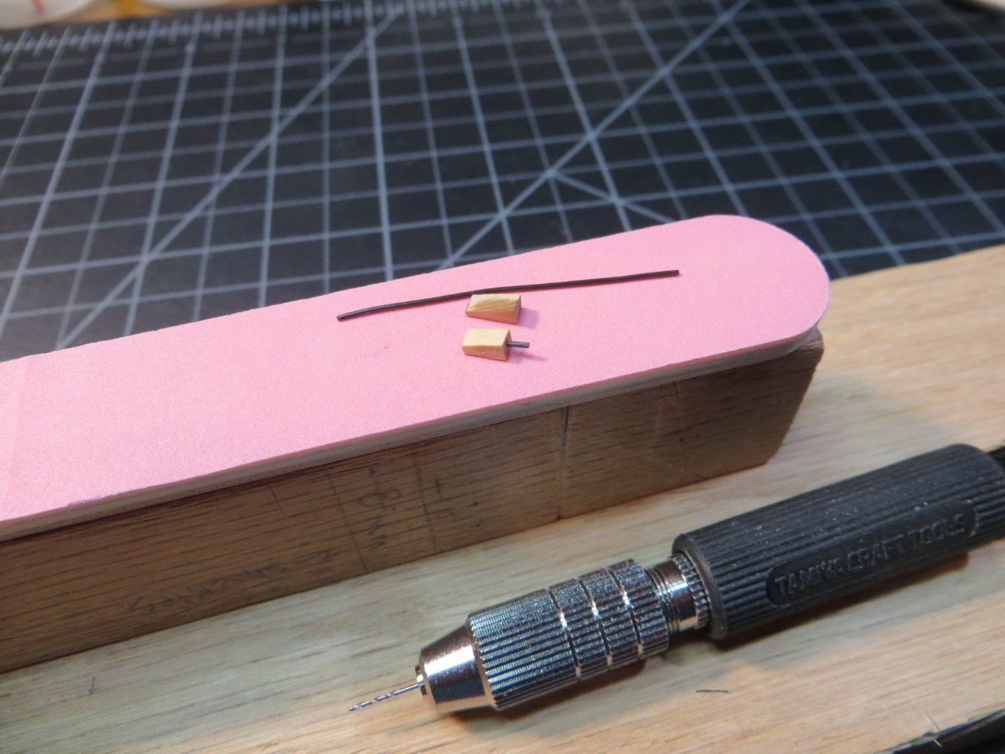
 Head Rails (Part 1) It seems that pretty much everyone agrees that making the Head Rails is one of the most difficult steps on the Rattlesnake. There isn’t a lot of detailed explanation in the build logs for this topic. Jon Gerson’s log is about the best explanation and has lots of pictures. Gregory gave me a link for the head rails on HMS Winchelsea. It helped to see a similar design. Due to the multiple steps and lengthy process, I’m going to split this topic into several posts. Here is how I did it and what I learned. The Upper Wale Cheeks, Upper Stem Rails, Lower Wale Cheeks & Lower Stem Rails make a curve on two planes. Therefore, they have to be made as 4 separate pieces. I discovered that, even though I made the stem from the kit provided laser cut wood, the dimensions of this area on my ship are smaller than the plan. I had trouble making the fox carving small enough to fit into the space between the stem rails. I had to do some extra sanding to make it fit. Everyone’s ship is a little different! I made each of the 4 pieces below with the same method. Use tracing paper to get the shape off the plans. Transfer that to some cardboard stock. Test fit the cardboard shape on the ship and adjust as needed. Transfer the cardboard outline to a piece of sheetwood. Cut it out using a jewelers saw. Use a sanding drum with the Dremel and my newest purchase, a benchtop disk sander to achieve the final shape. (This sander saves a lot of time!) I ended up using 3/32” thick sheetwood for most of the parts. The 1/16” was too flimsy and the pieces easily broke where the grain went vertical. I only used this for the lower stem rails. I needed something smaller in this space. 1. Upper Wale Cheeks – Started with this. Made from 3/32” sheetwood. These are wide horizontal pieces that sit below the anchor hawse holes. It makes a curve from the hull into the bow stem. 2. Upper Stem Rails – The next piece that extends from the forward edge of the cheek up to the tip of the stem. These pieces need to blend together. Use 1/8” sheetwood. These have a curled scroll at the top. 3. Lower Wale Cheeks – are parallel to, but below the upper cheeks. 4. Lower Stem Rails – a curved piece that flows from the lower cheek and runs along the lower edge of the stem up to the feet of the figurehead. Made this from 1/16” sheetwood. All of the above pieces have a molding cut into their edge/face. I made a groove to match the work I have created on other hull pieces. This time I started by using a ball tip stylus to make an impression in the wood. This impression was deepened with Artesania scrappers, files and sandpaper. Everything was test fit on the ship. I inserted a dowel the diameter of the future bowsprit, and also the figurehead for test fitting. Minor adjustments were necessary with the figurehead. All the pieces were painted with the same yellow ochre as on the hull. Cutting the Head Rail from 3/32” sheetwood Carving the molding cut and some of the tools I used One of many test fits! Note the blue cardboard template for the lower stem rail Painting the port side pieces with yellow ochre 5. Fox Carvings – are positioned on the stem between the upper and lower rails. I used 3/32” sheetwood. They were made using mini-files and sandpaper Transferring the carving from the plans to the sheetwood The 4th & 5th iterations of the Fox carving. Not the most artistic pieces, but not too bad for me! The Indian Figurehead after painting. I applied a coating of spray lacquer for protection Views of the stem after gluing in place This seemed like a good stopping point. I’m finishing up the head rail now. I will post some more soon. Let me know if you have any questions or comments. Thanks, Ed
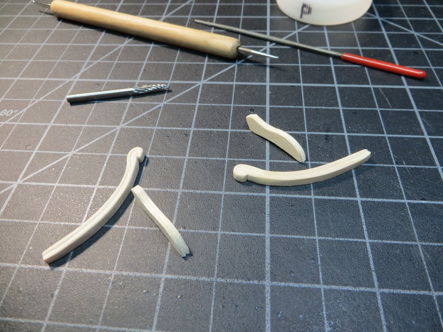


-
Thanks for the link to Chuck's Winnie. I wish that Model Shipways' plans had better drawings of the head rail pieces. Something I could cut out to use for a template. It may take several attempts to get an acceptable result. Looking at Chuck's model makes me feel like a real 3rd rate hack!!! Thank You Gregory!
-
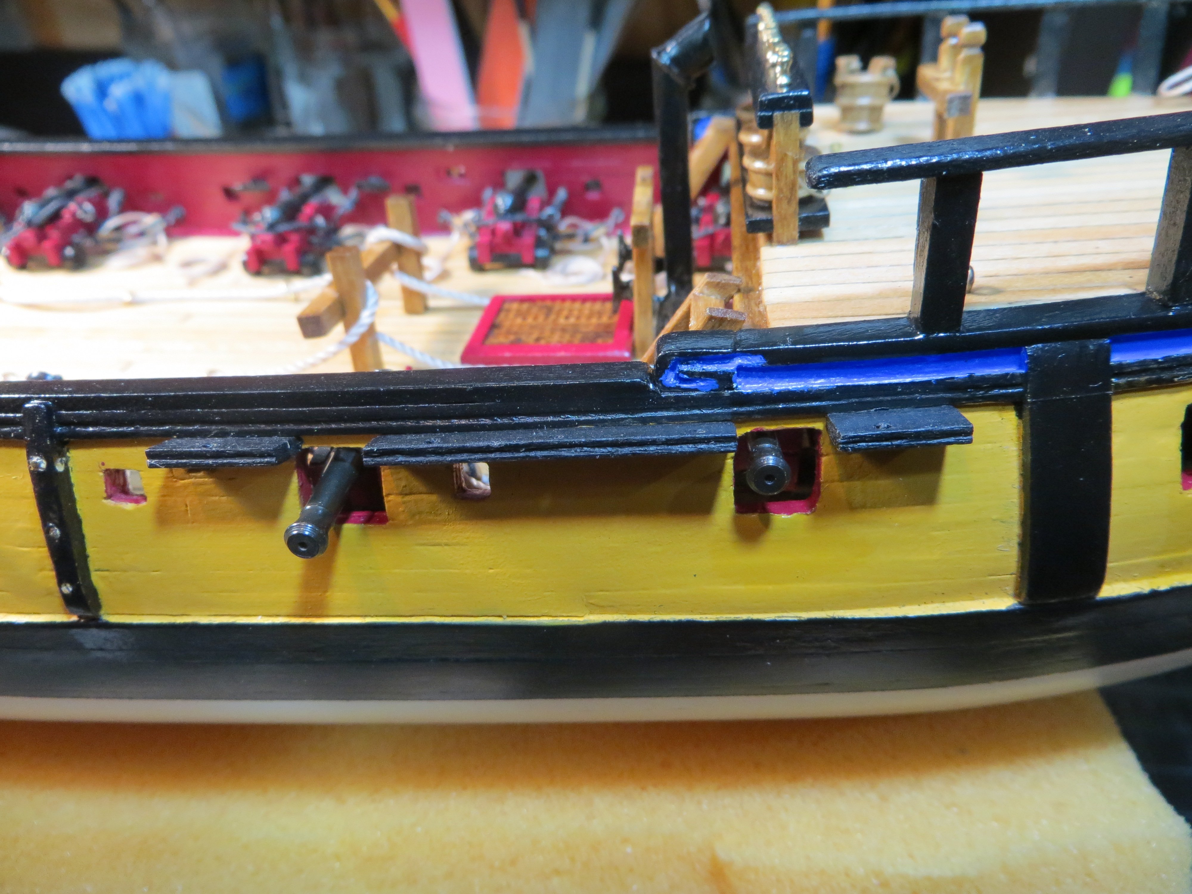
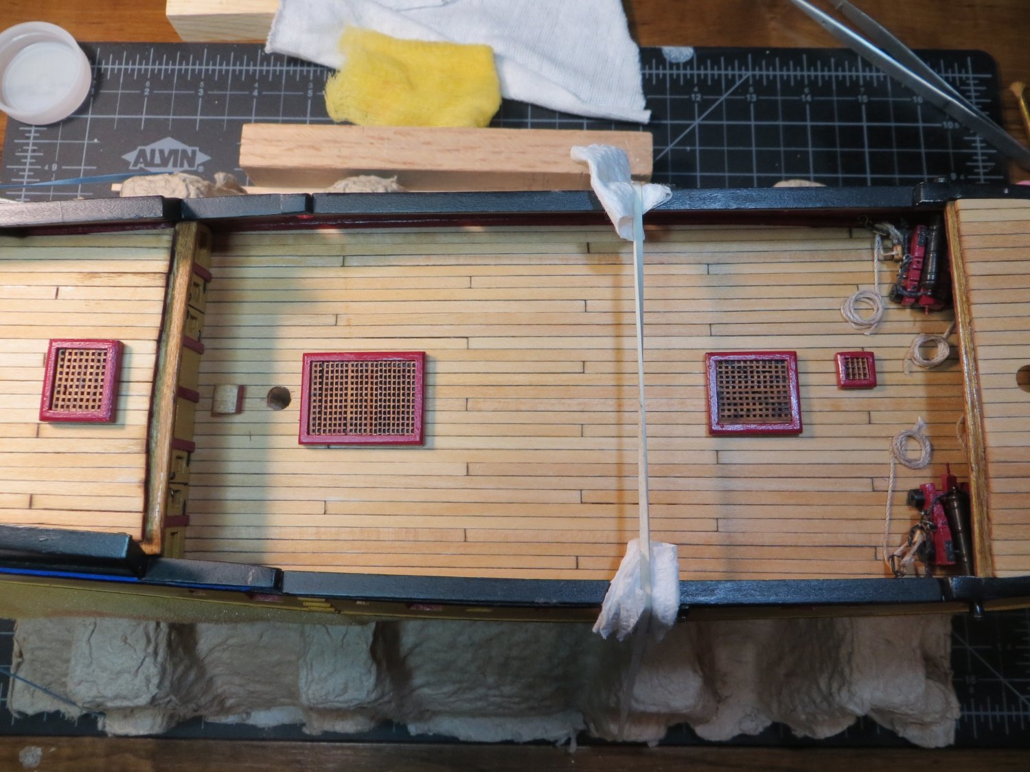
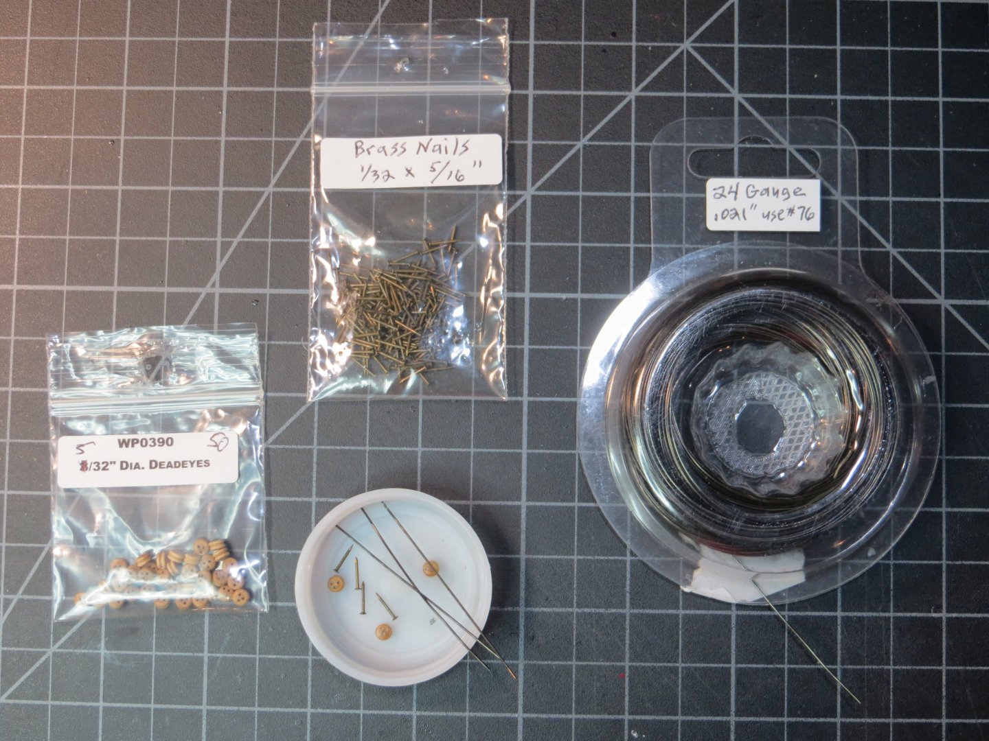
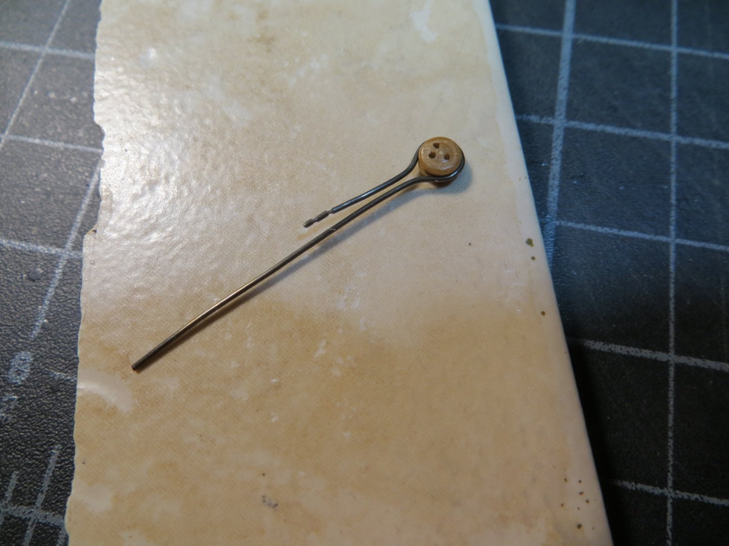
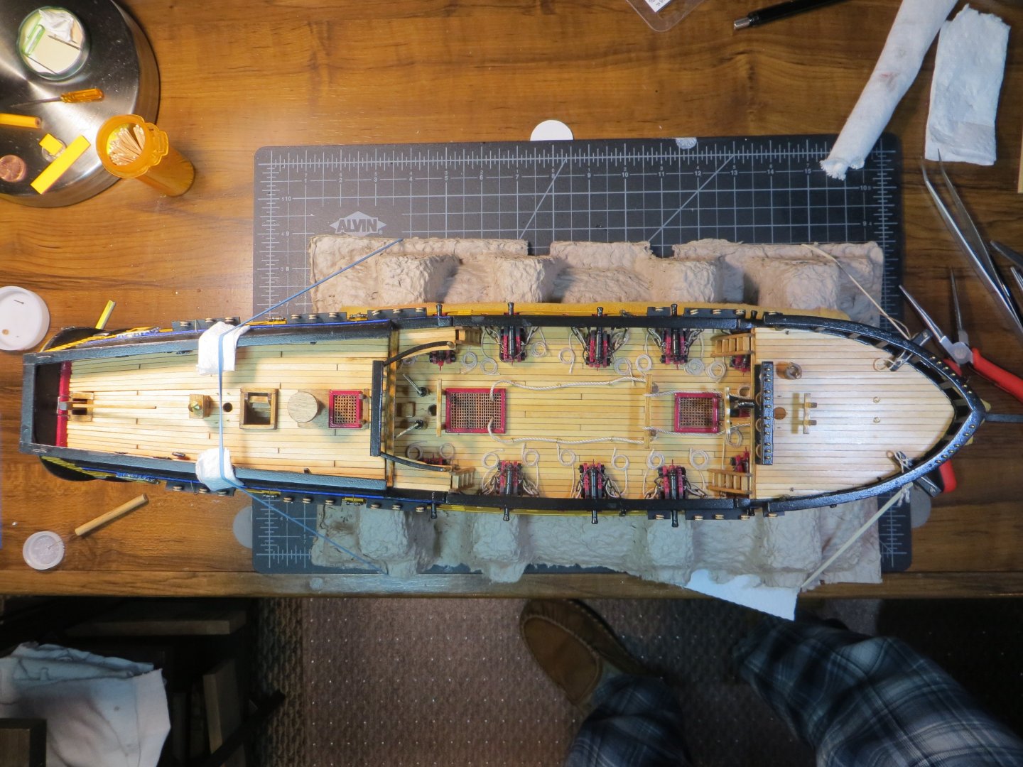
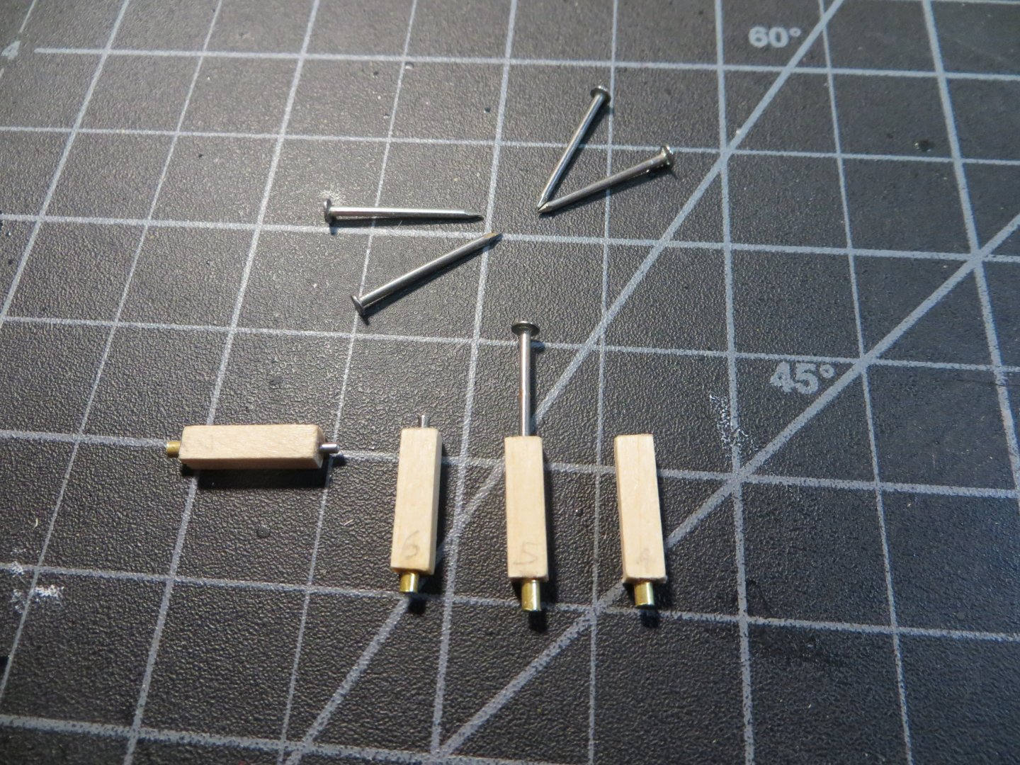
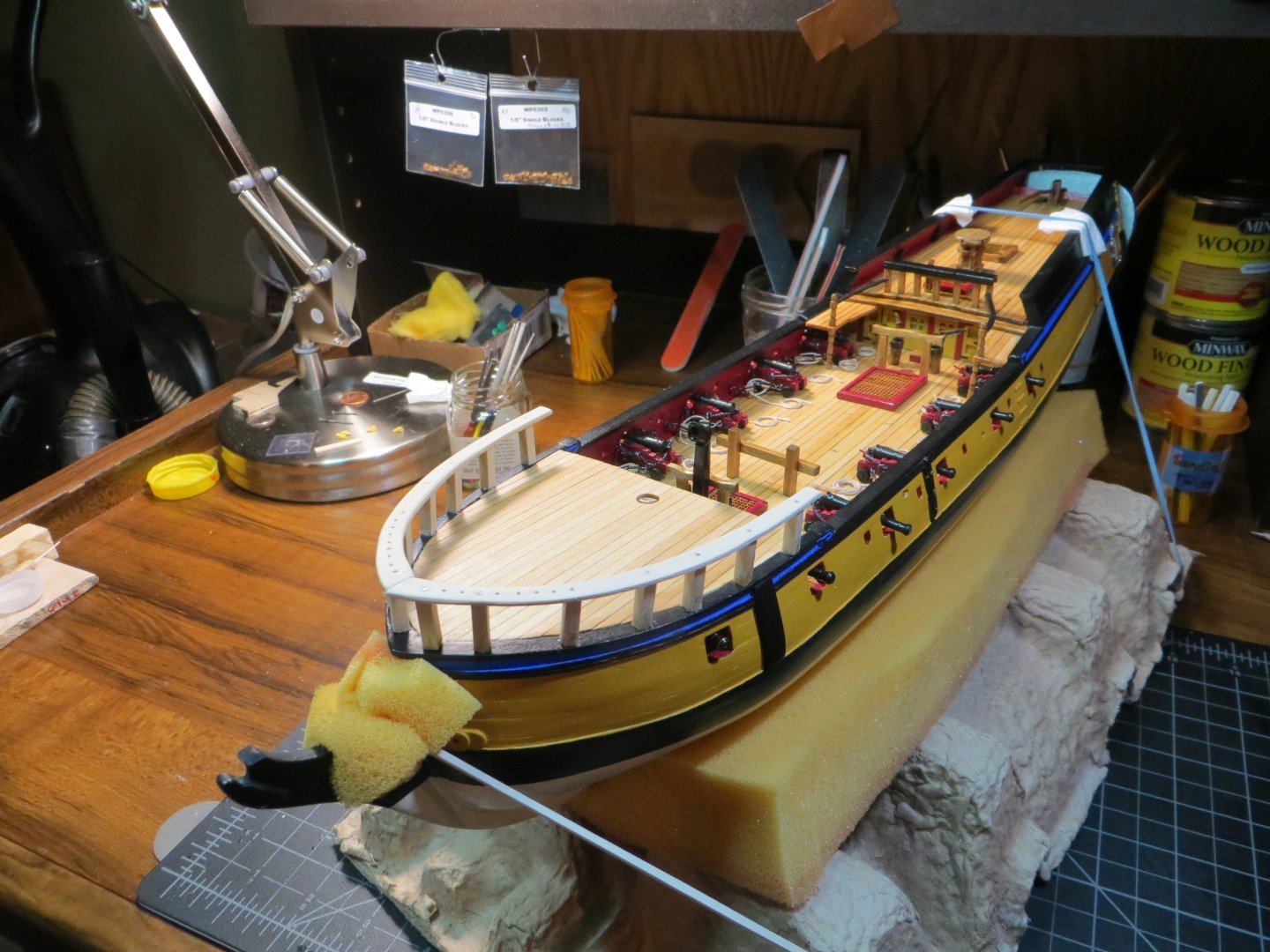
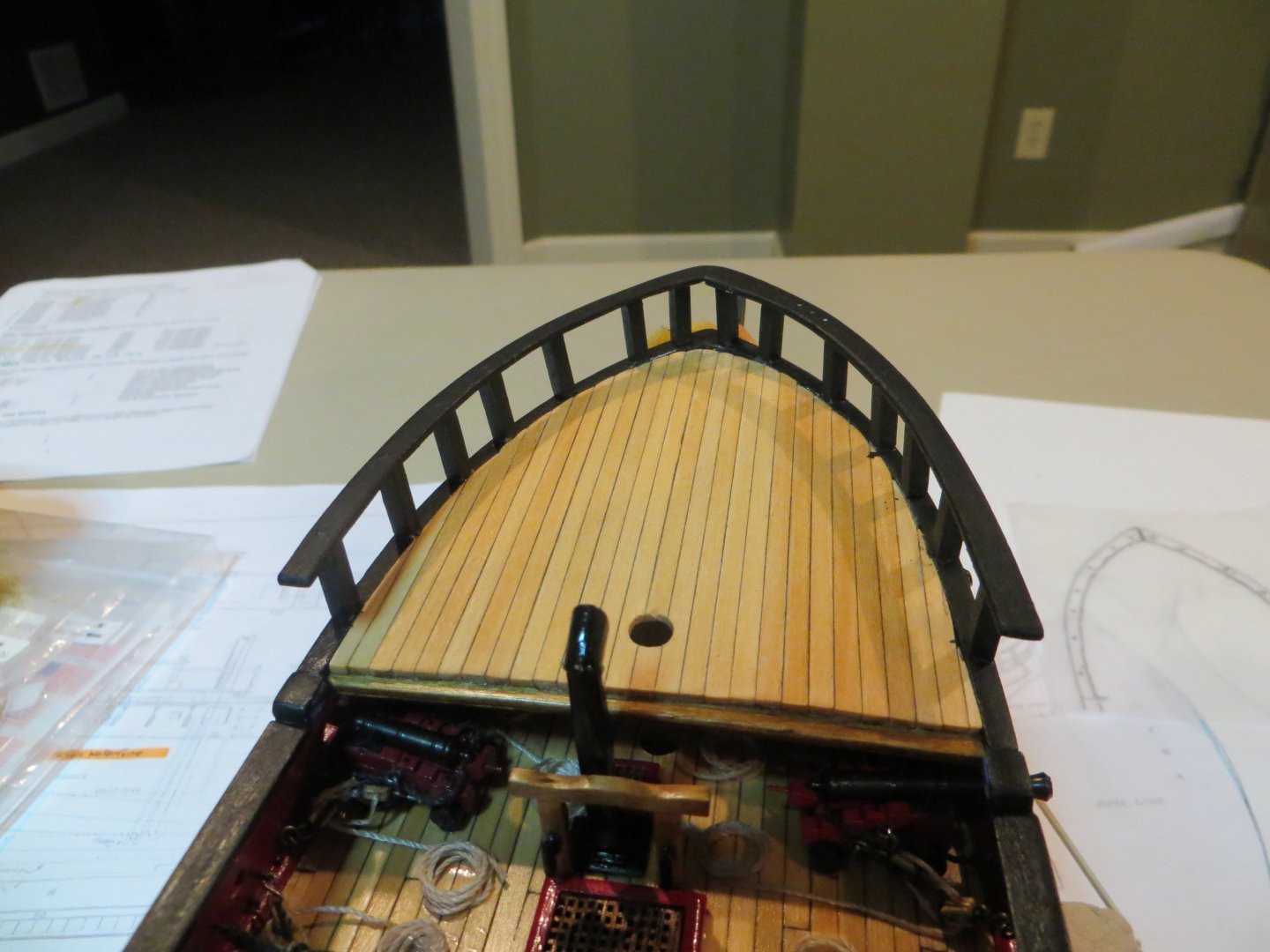
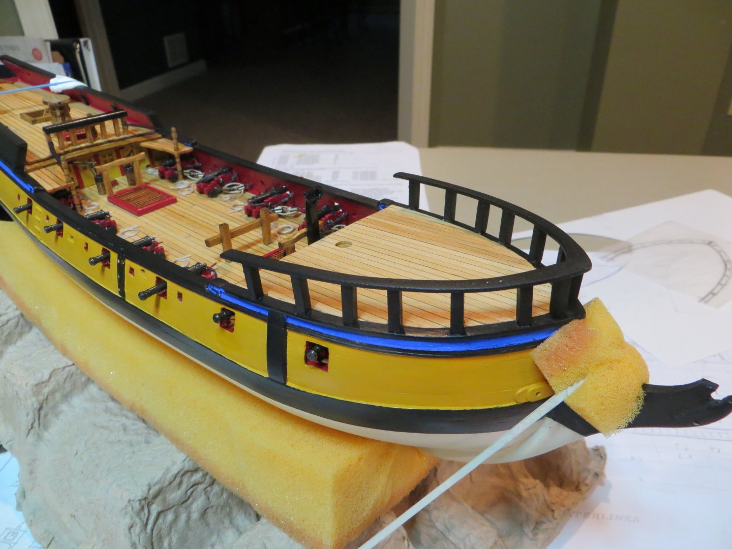
Deadeyes & Chain Plates On my Bluenose build I faked the chain plates by using black card stock strips. This build, I’m upping my game a bit to the steel wire model option suggested in the instruction manual. I decided not to go with the soldered 3-piece chain plate option. I think these look pretty good. There are 28 deadeyes/chain plates that need to be installed. It gets a little tedious, but I got a good technique going. I took the following pics to show the process I used. The first step was to mark the position of the nails at the bottom of each chain plate. I assembled three of them at a time since 8 of the channels require three deadeyes each. Here are the parts required for each one. I purchased the brass nails from Model Expo. These worked well, except I had to cut them down when inserting along the open gun deck. They would have come right thru the inboard bulwark! I used round-nosed pliers to bend a loop in the wire and inserted a deadeye The wire was twisted around the deadeye and the excess snipped off. Make sure the single hole faces down The assembled piece is slipped into the hole in the channel. The challenge is to make the loop in the bottom end of wire in the precise spot where the mark is located. A pilot hole is made at the spot and the nail inserted part way in. The wire is tightened around the nail. I apply a drop of thick CA glue and push the nail the rest of the way in. Here are the completed deadeyes and chain plates on the port side for the main & mizzen masts And here is the same side fore mast Full view of the deadeyes and chain plates on the starboard side Birds eye view of my Rattlesnake at the current stage of the build I also completed the assembly of the two open gun port lids. As promised, here are a couple of pics. They have not been glued in permanently yet. I will wait until the hull assembly steps are complete. I also need to add a coat of wipe-on-poly on the yellow ochre section of the upper hull. I’ve been waiting until all the wood parts are glued so I can still use PVA. My next step is the Head Rails. I am still trying to wrap my mind around how this is supposed to work! I’m studying other build logs and making my plan of attack on this difficult looking task. Thanks for looking in on my Rattlesnake! Ed


-
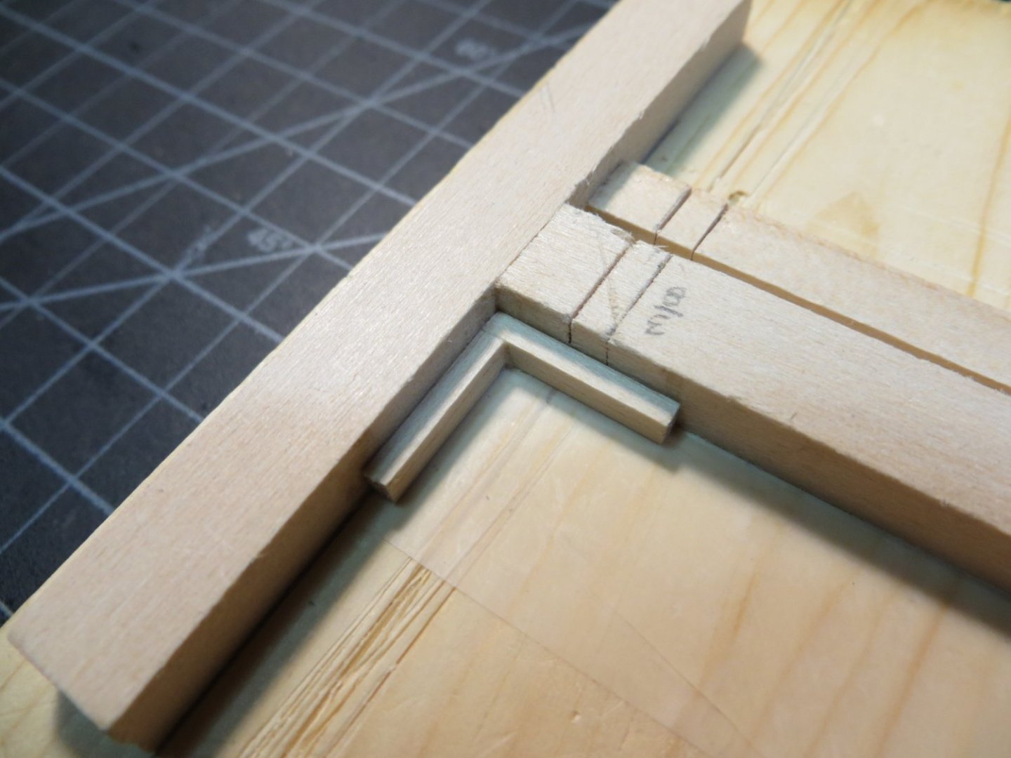
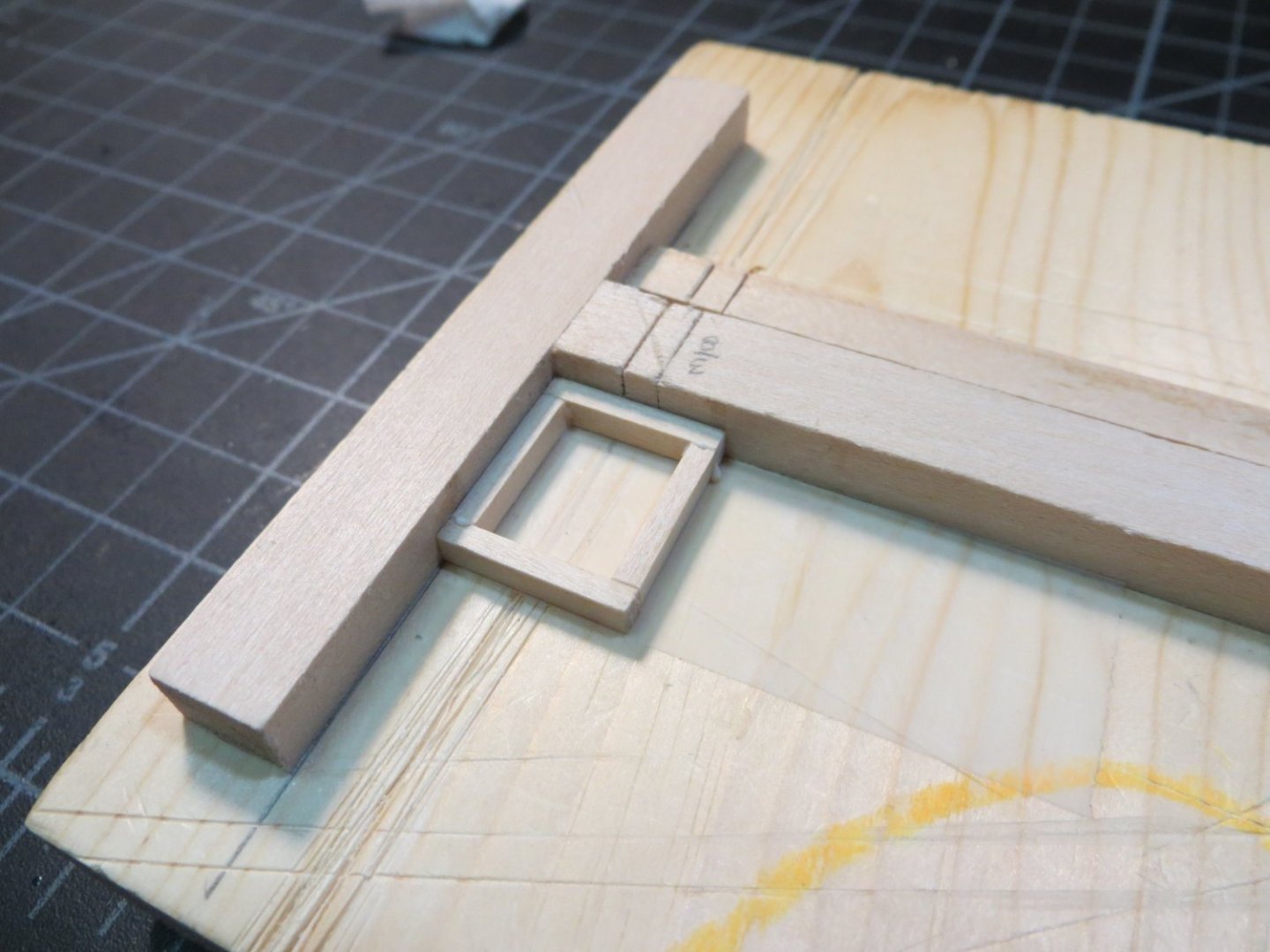
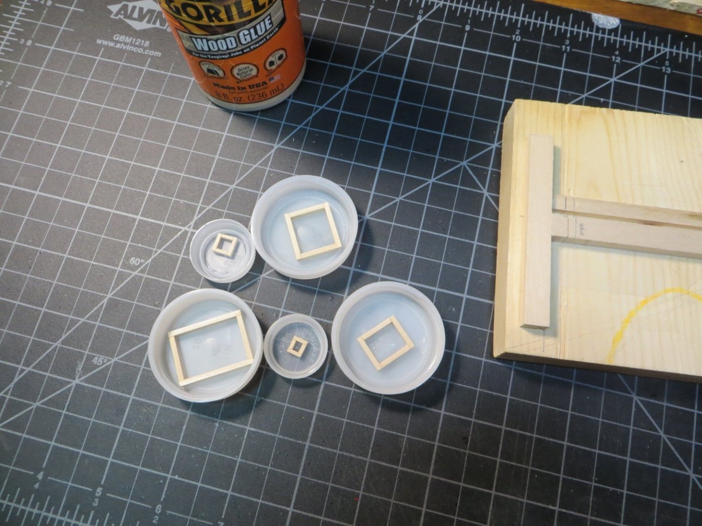
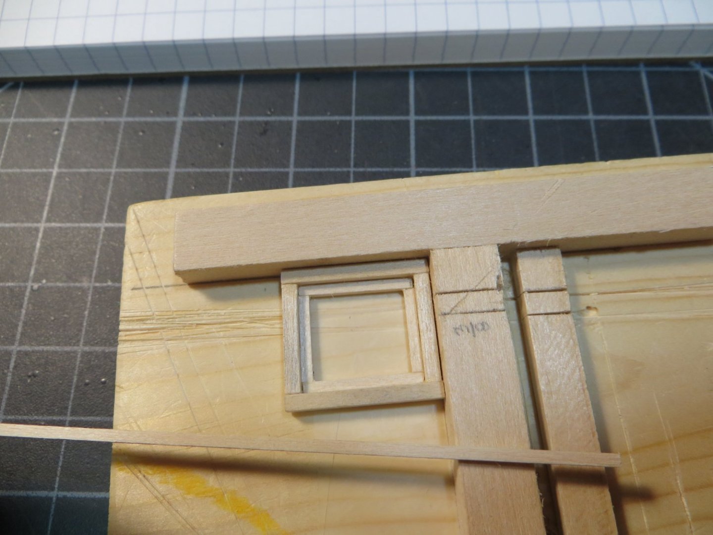
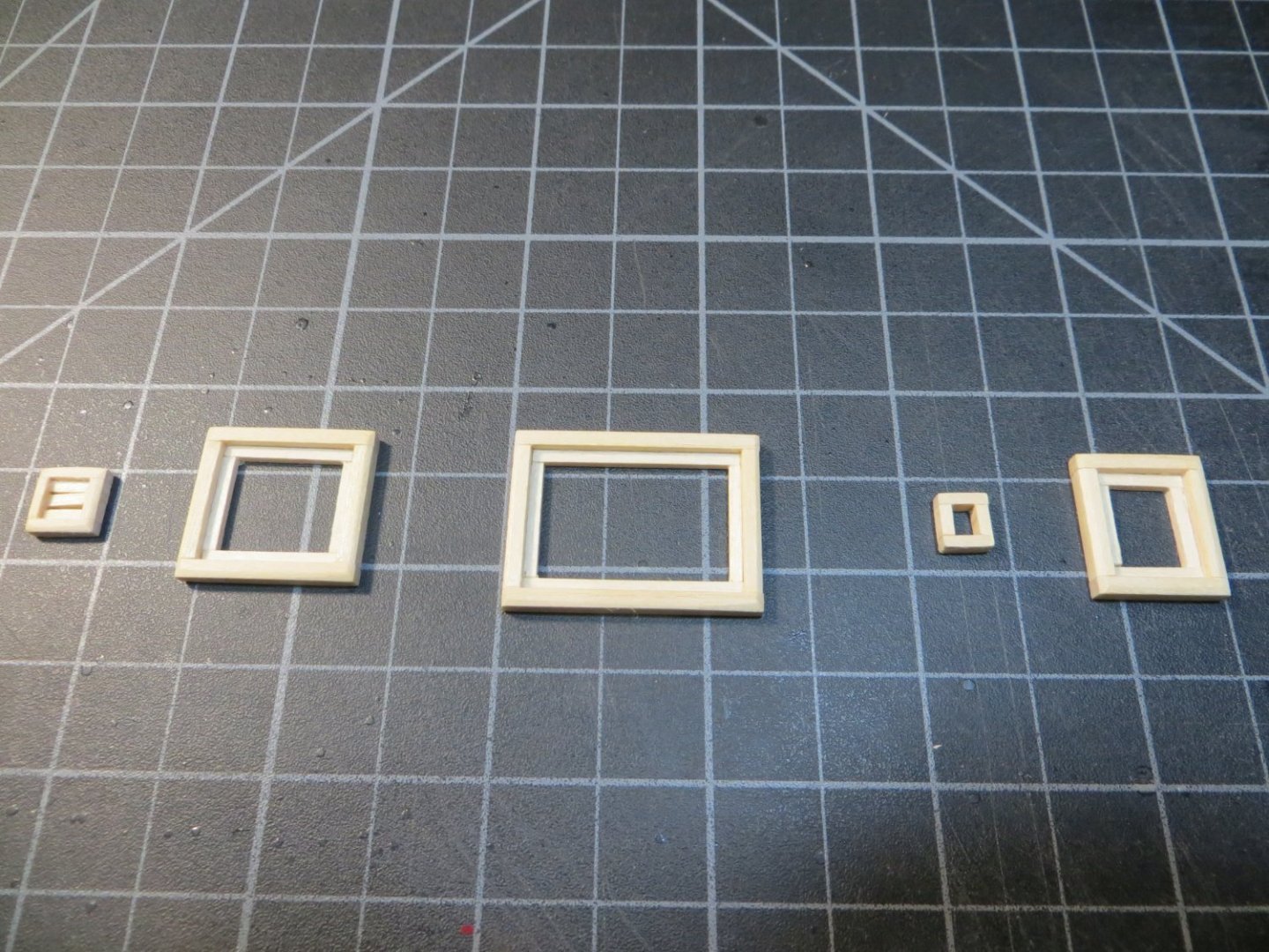
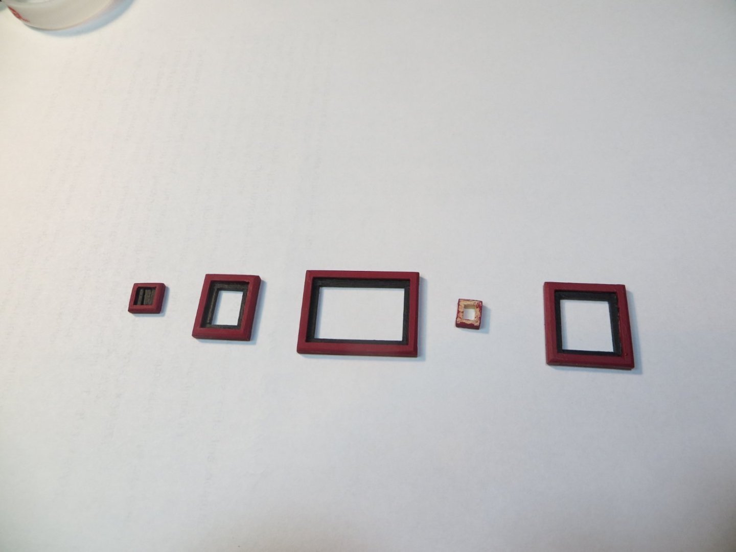
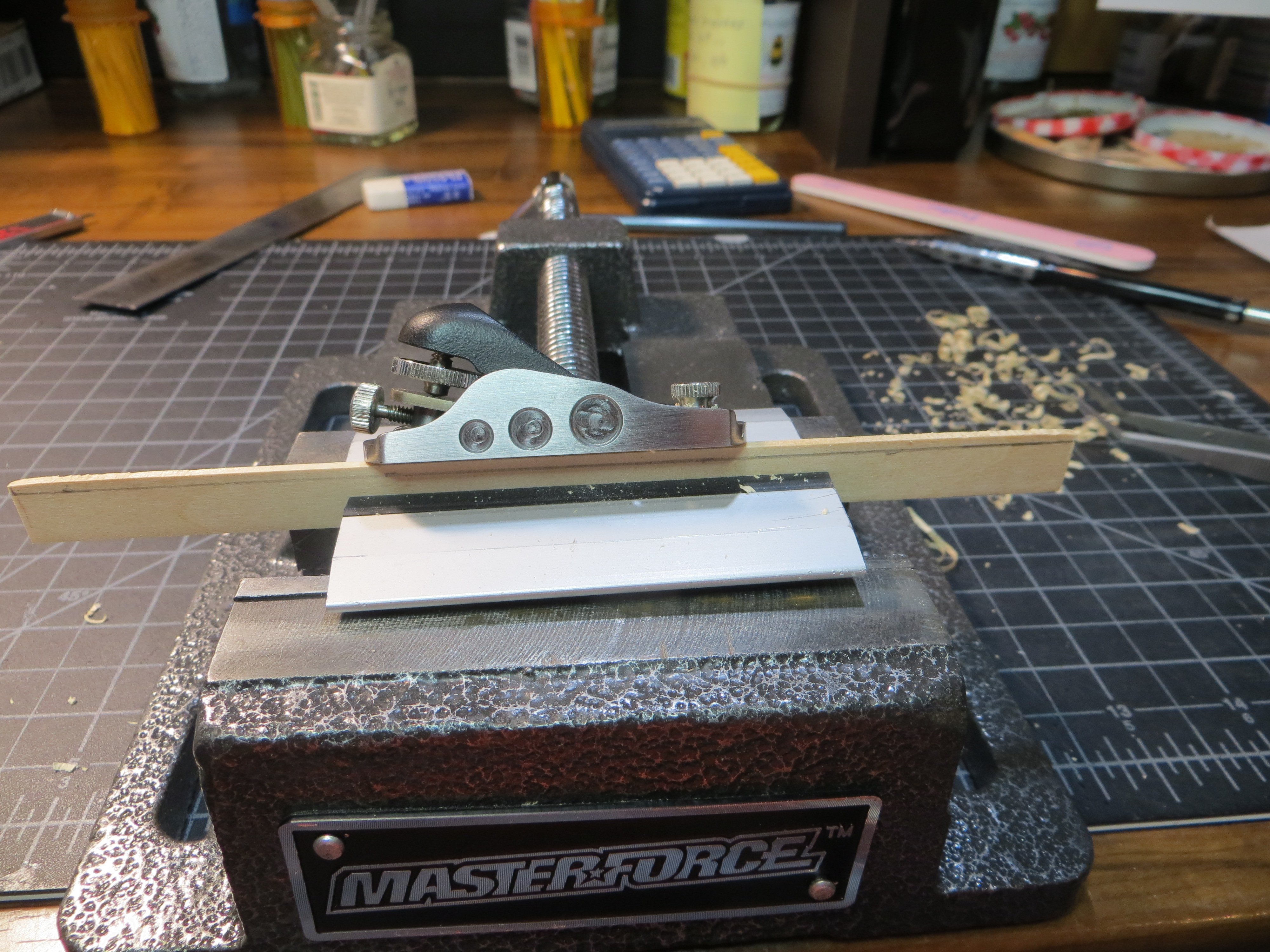
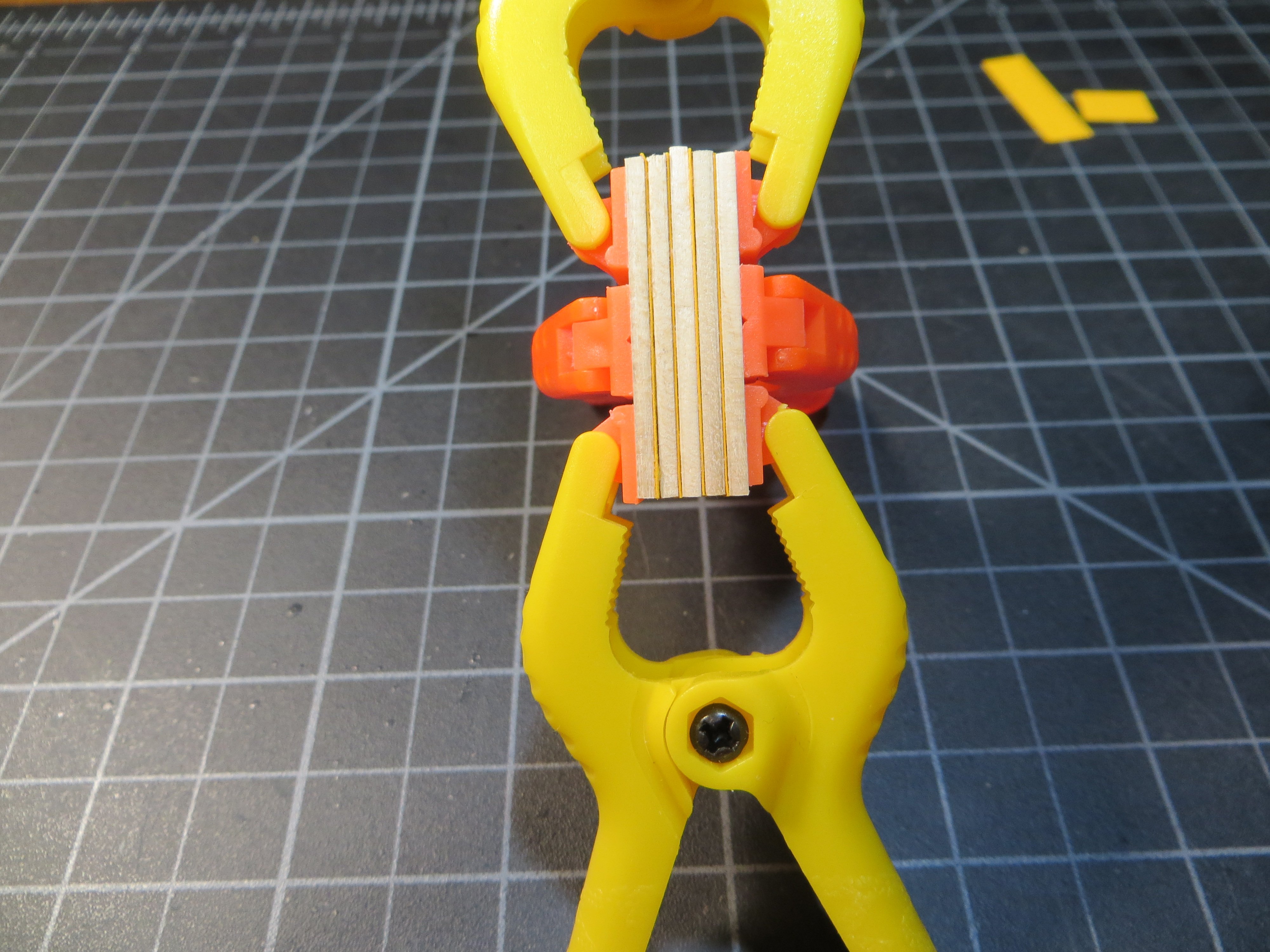
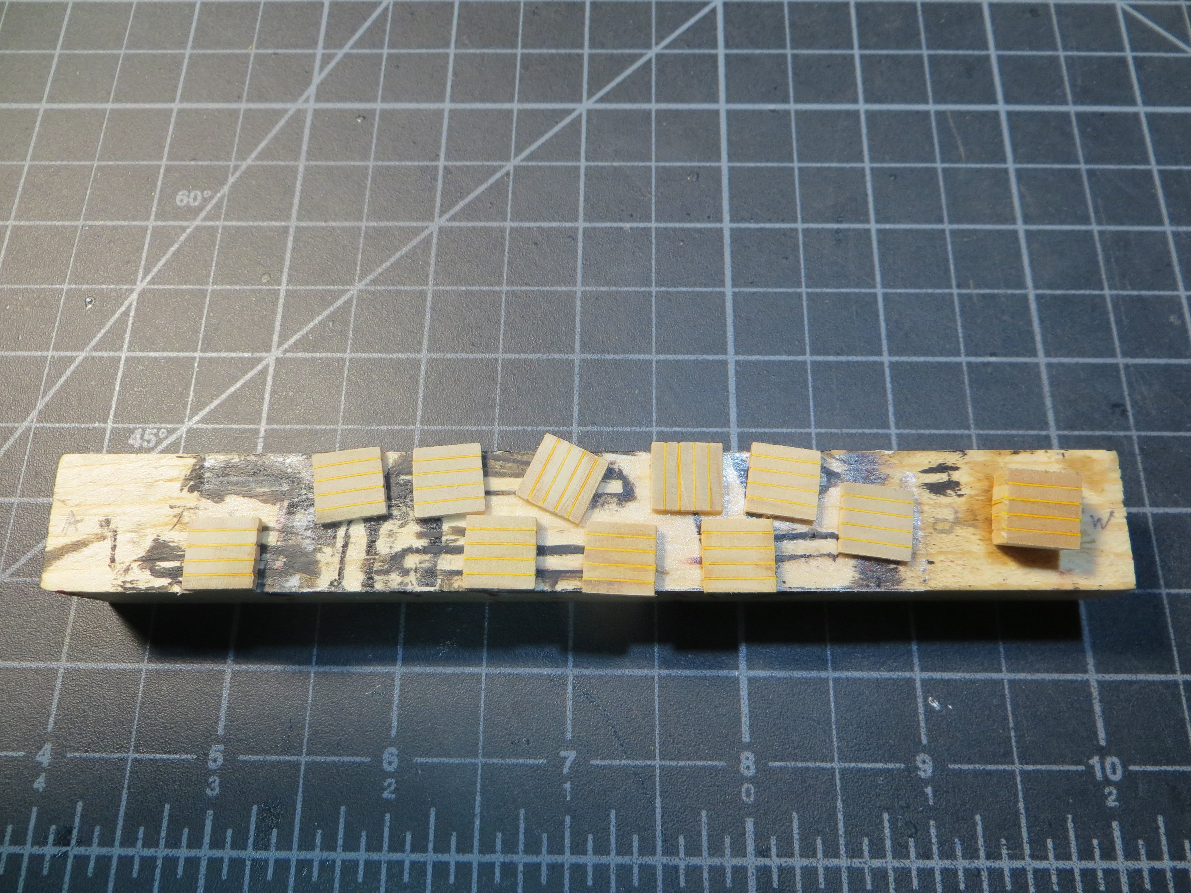
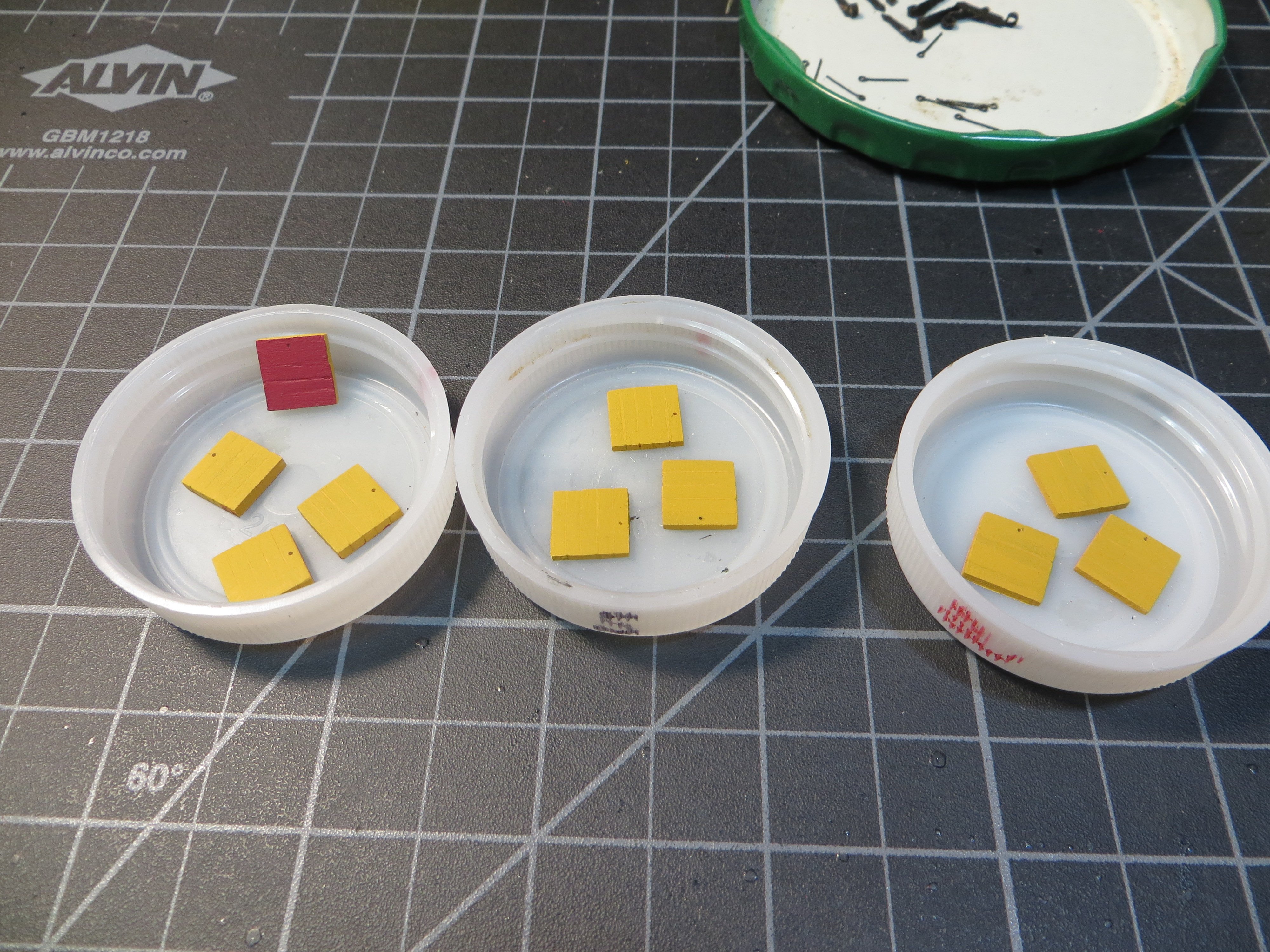
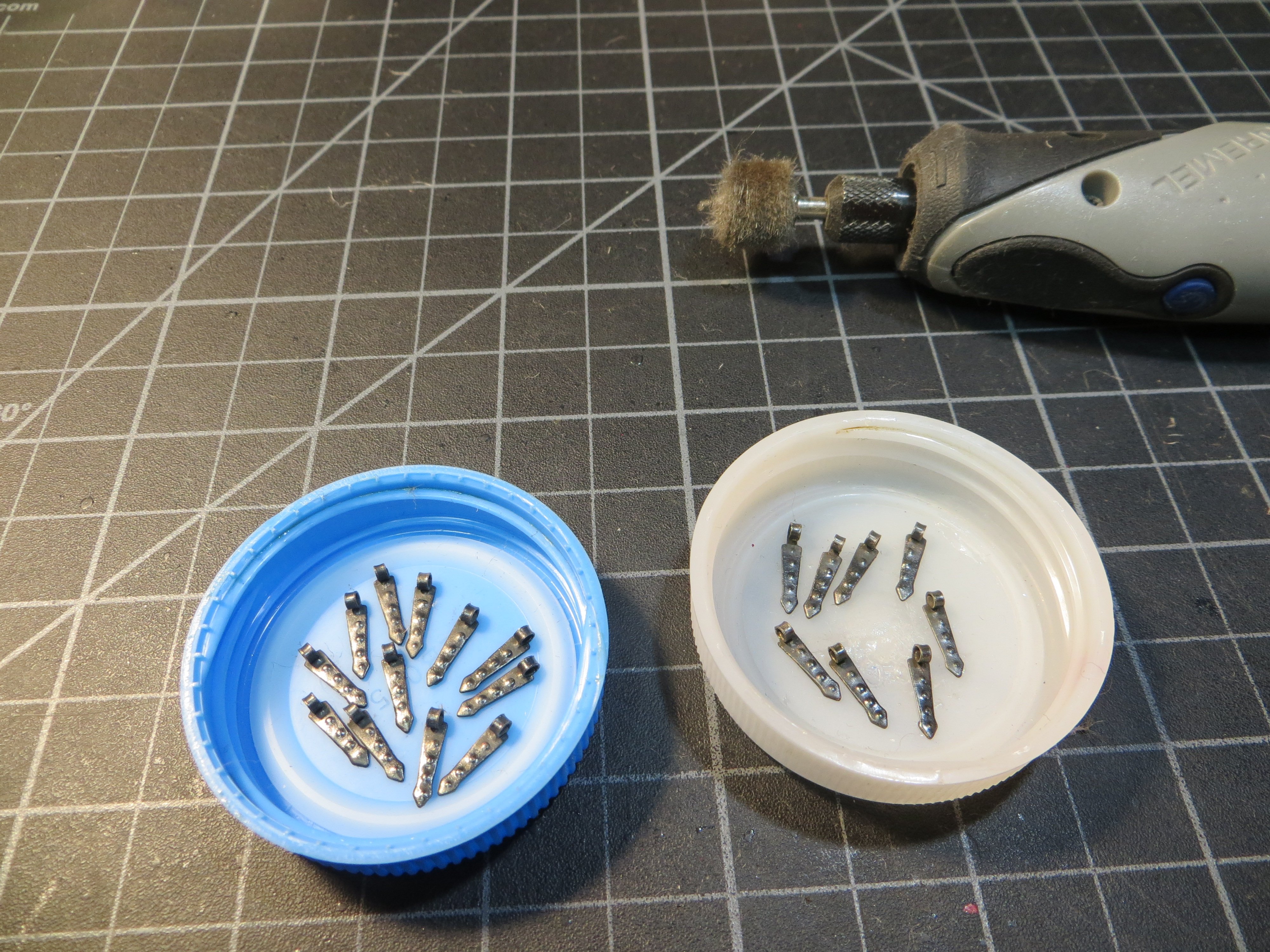
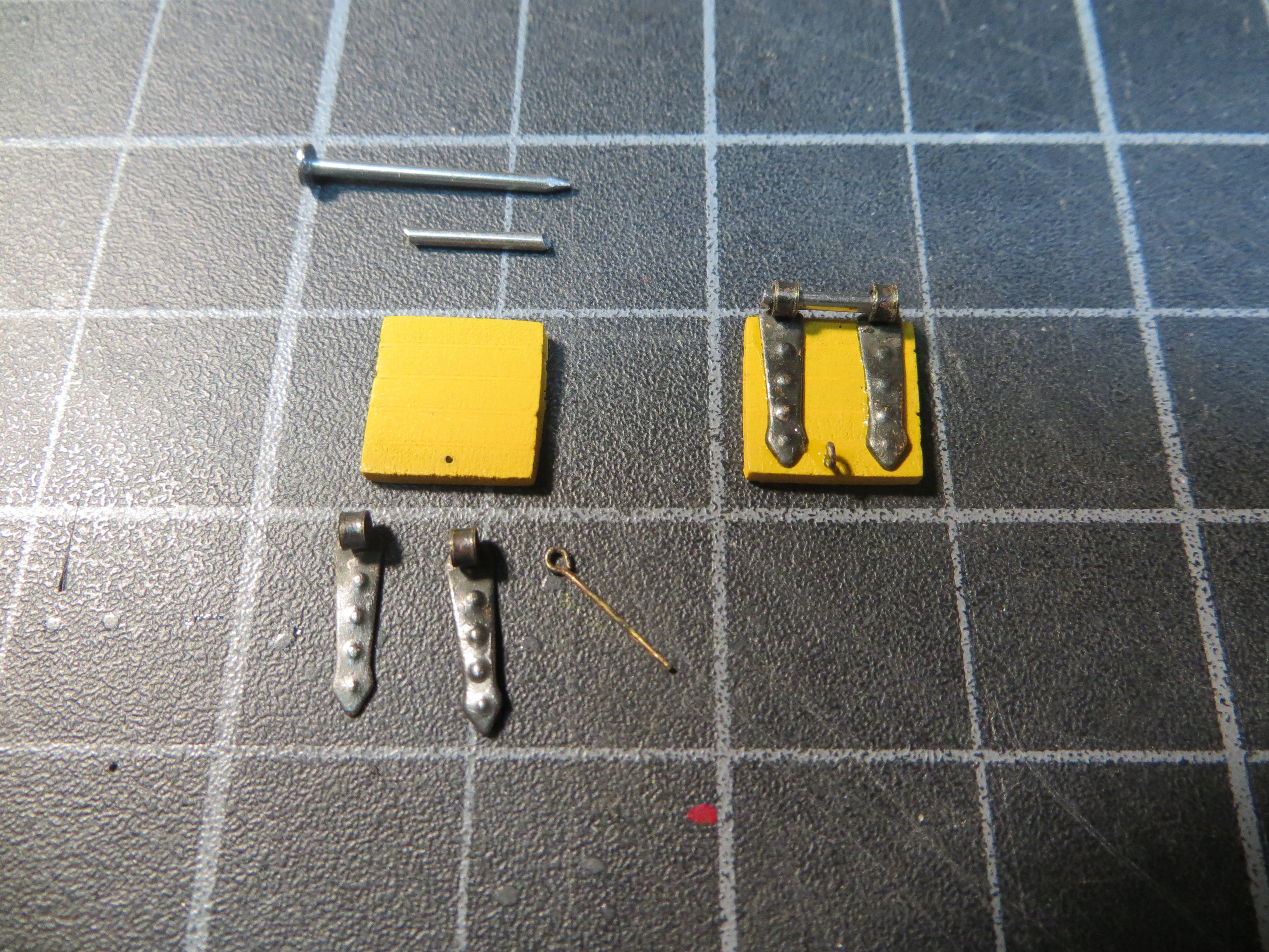
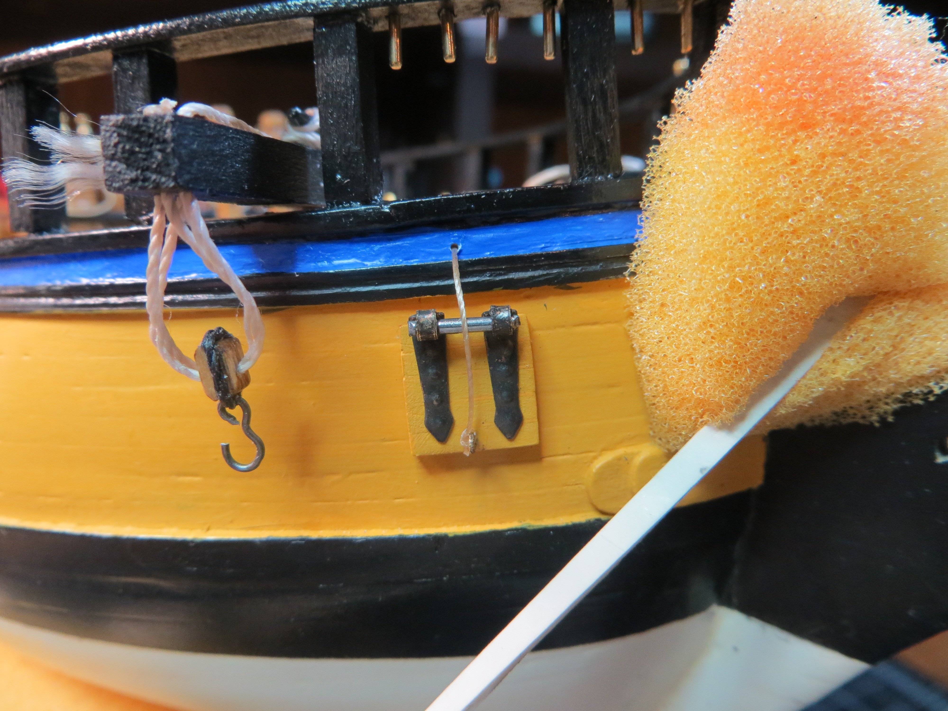
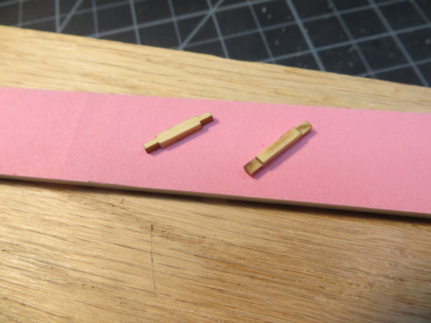
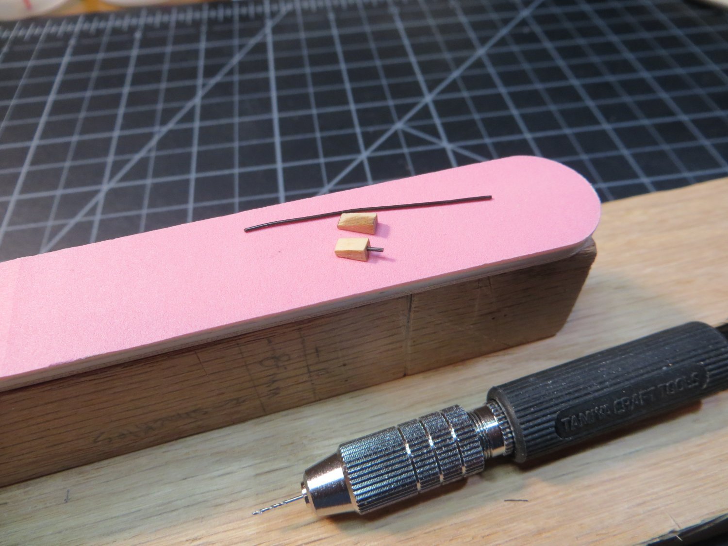
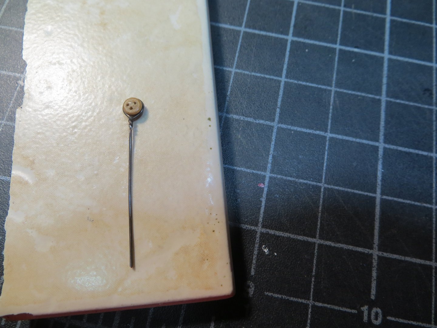
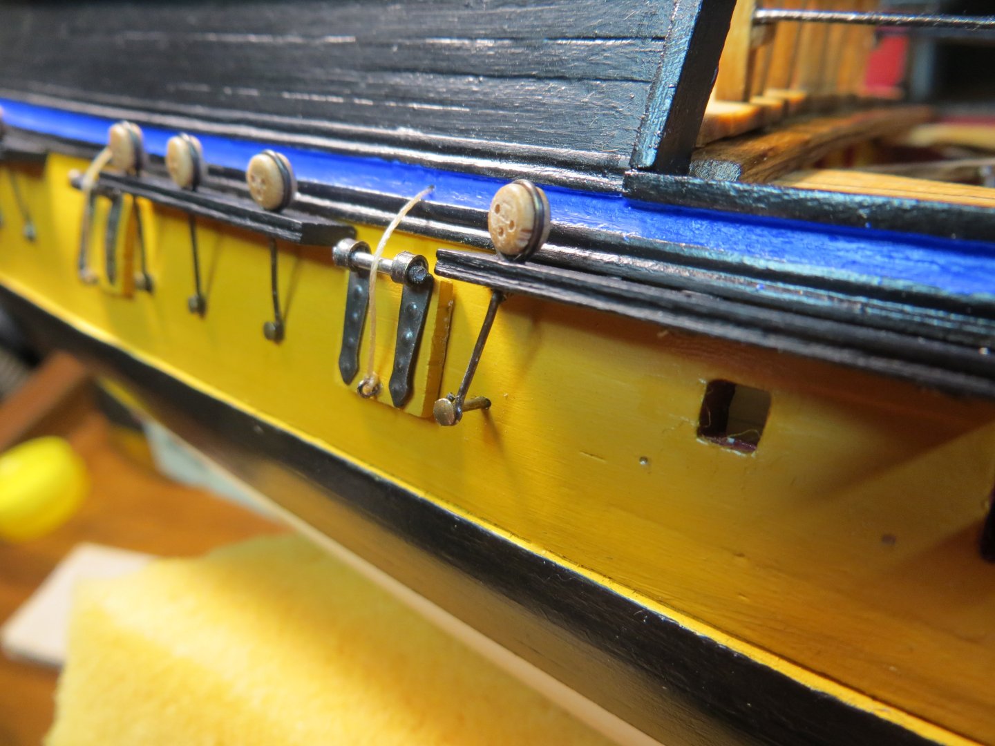
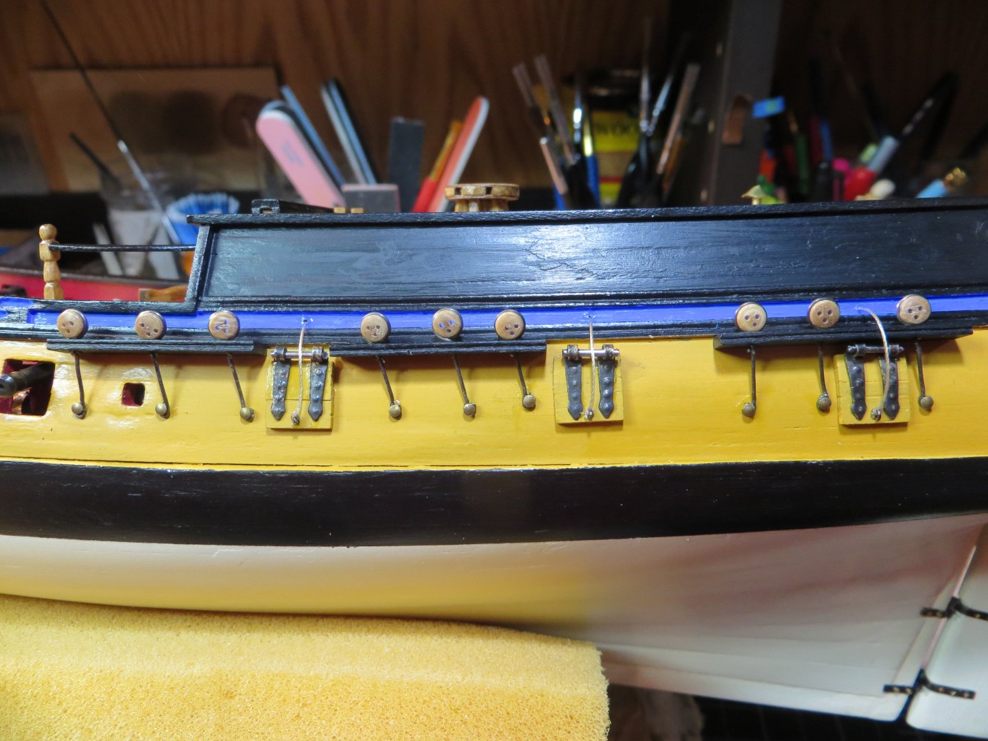
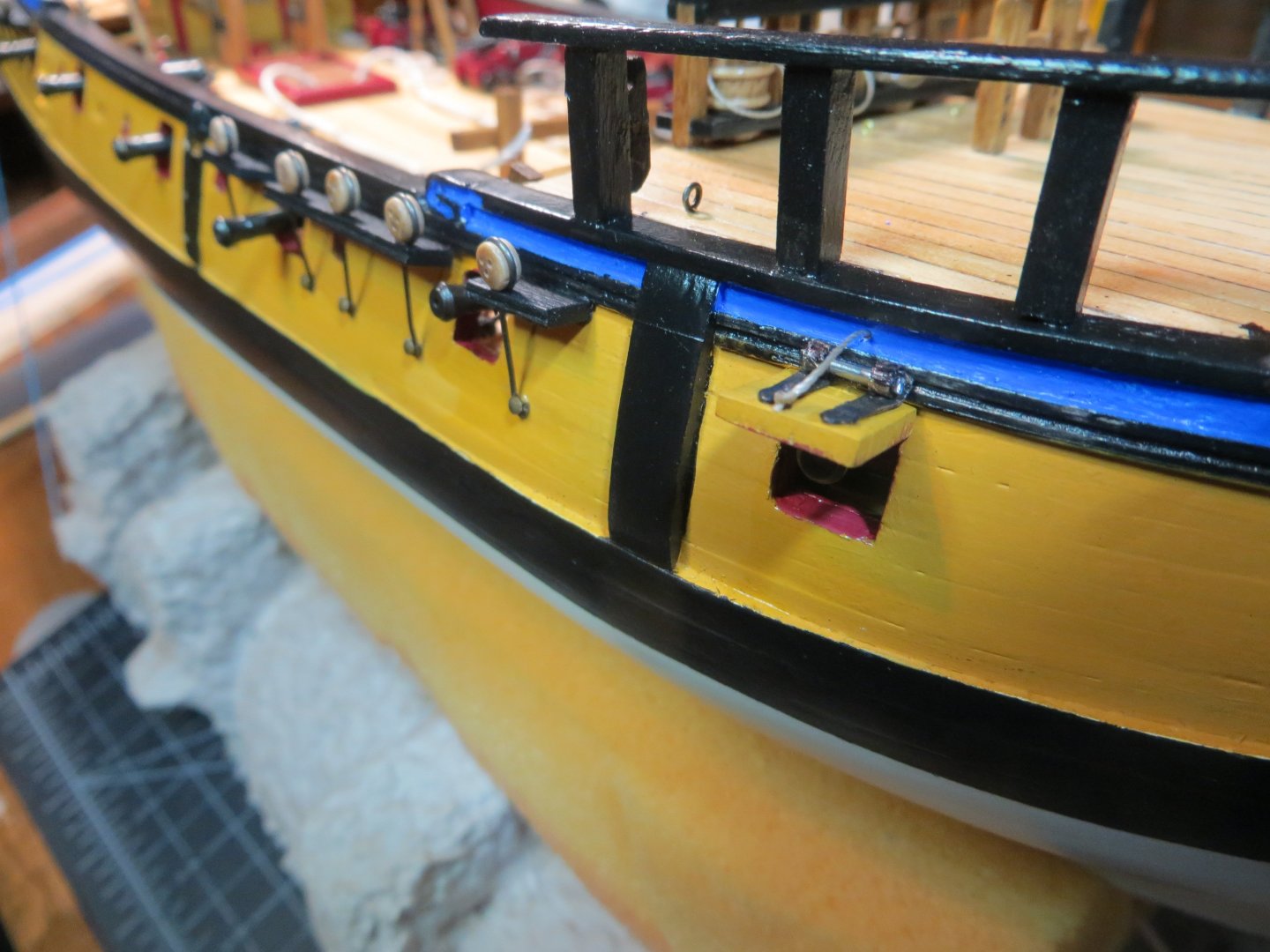
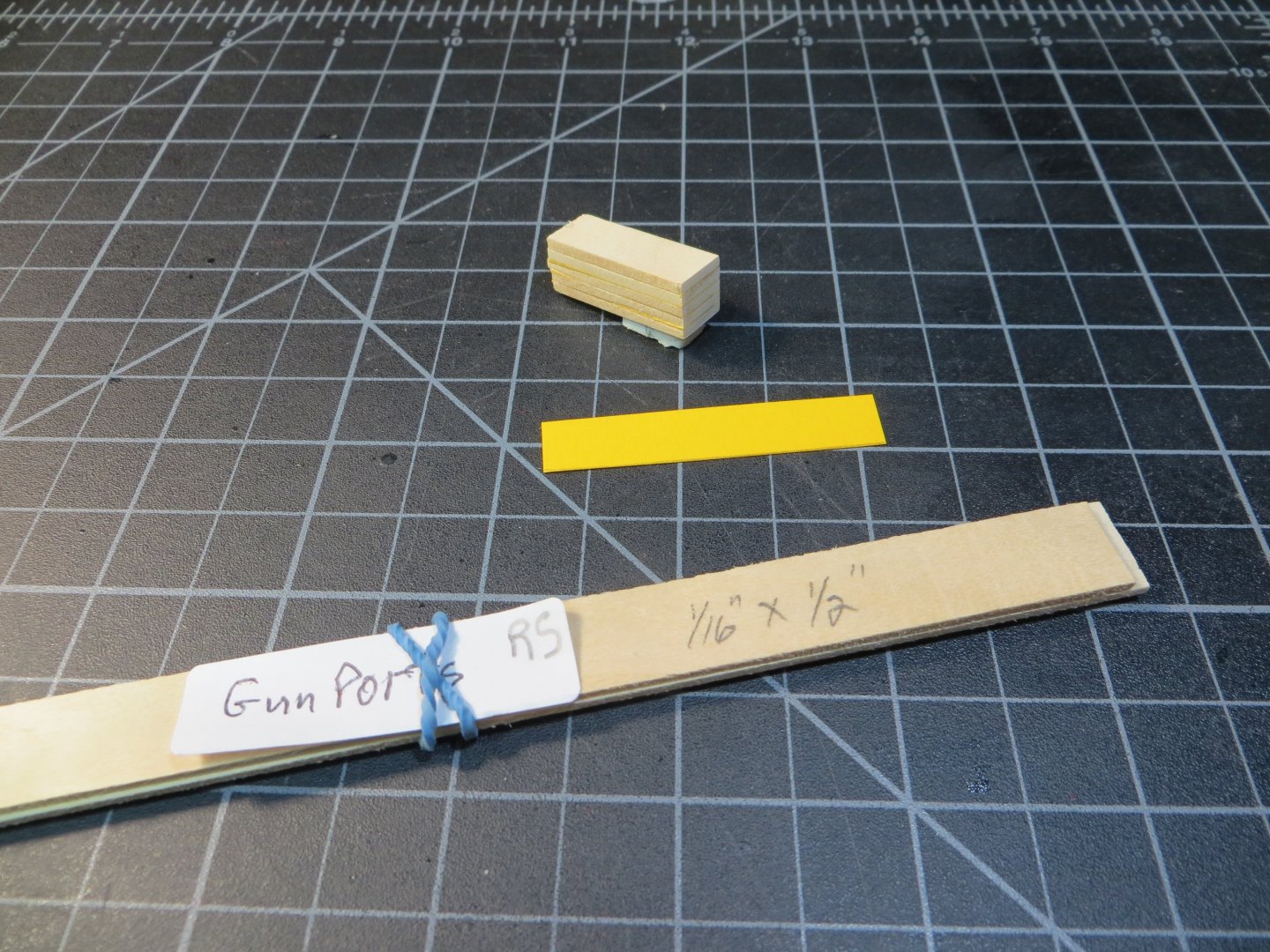
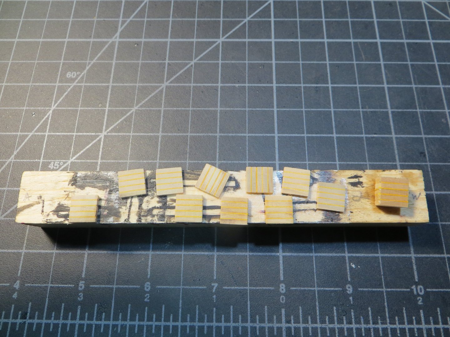
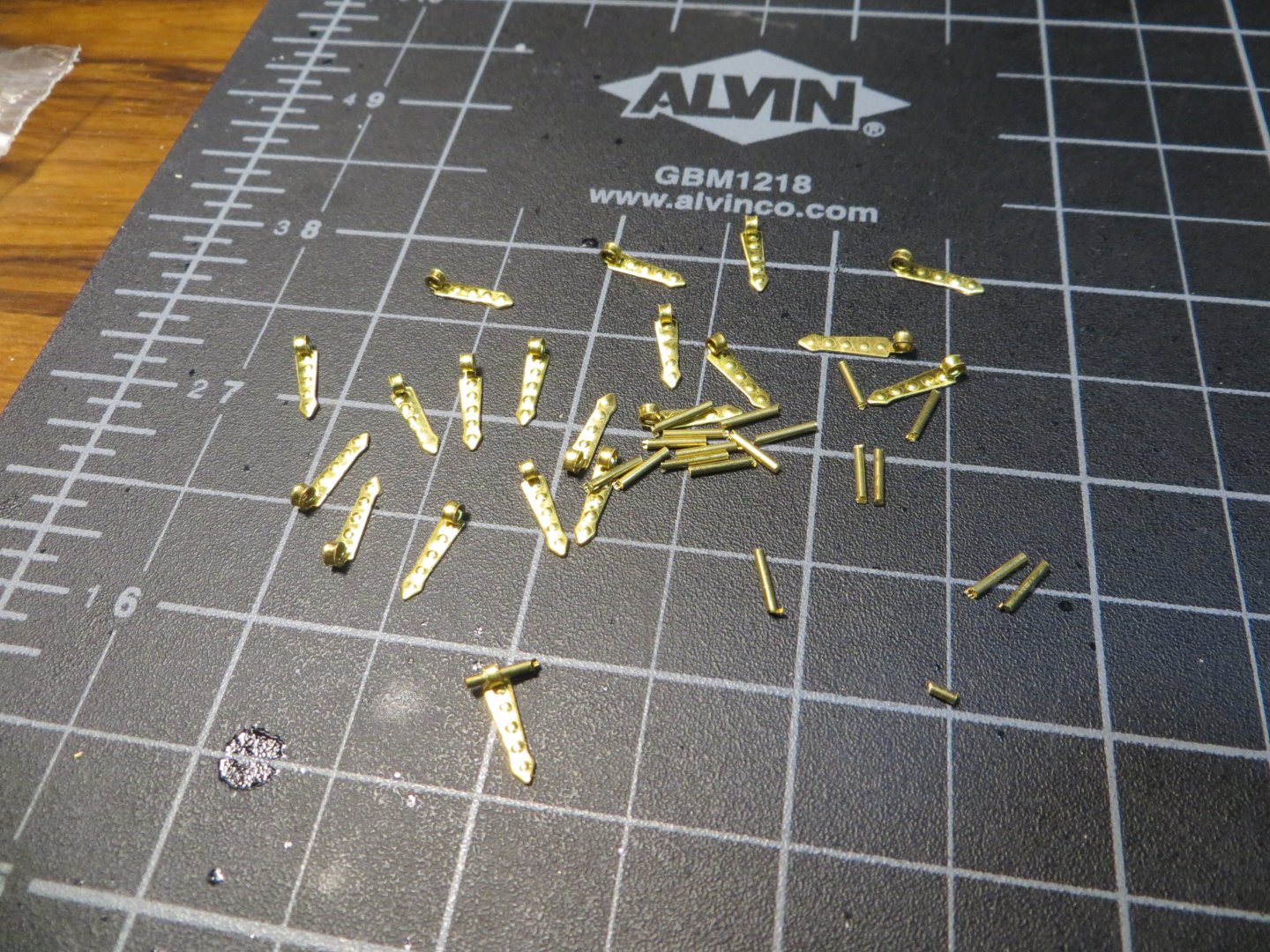
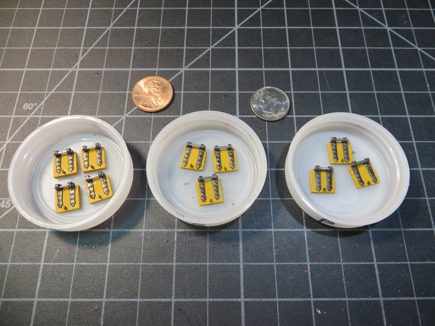
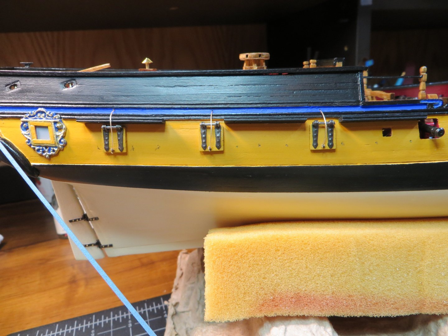
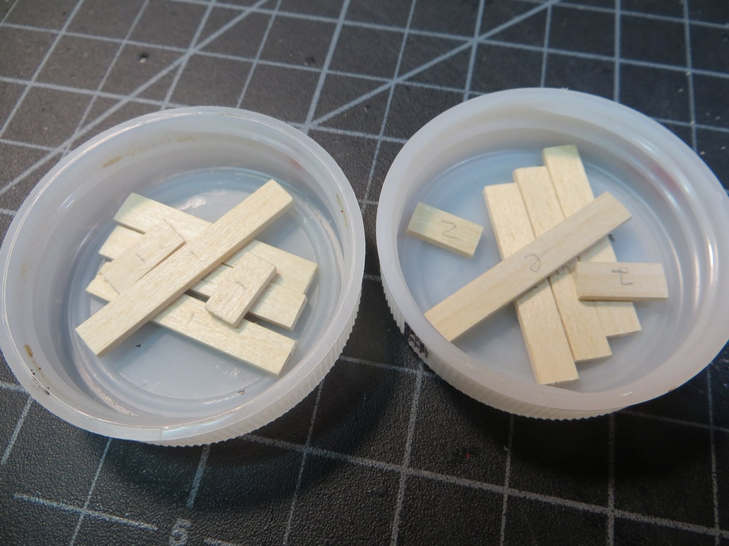
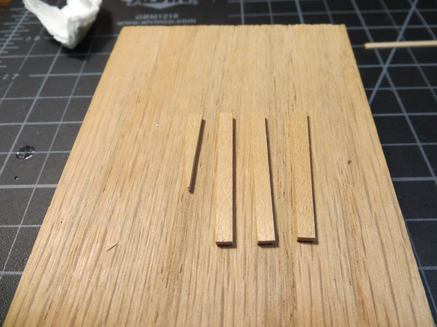
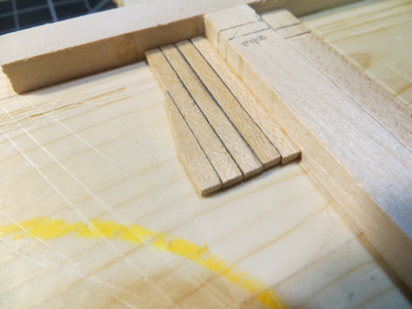
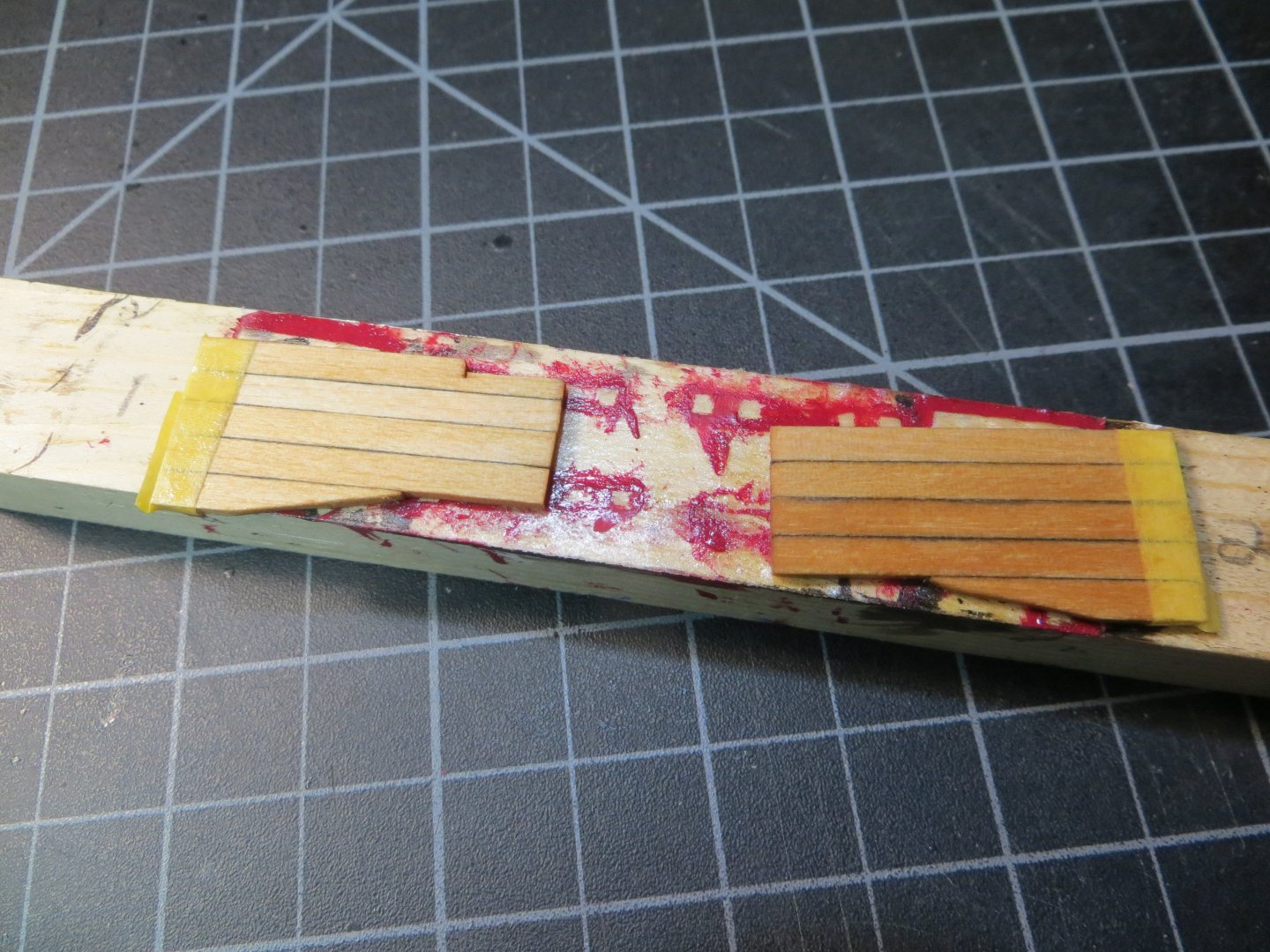
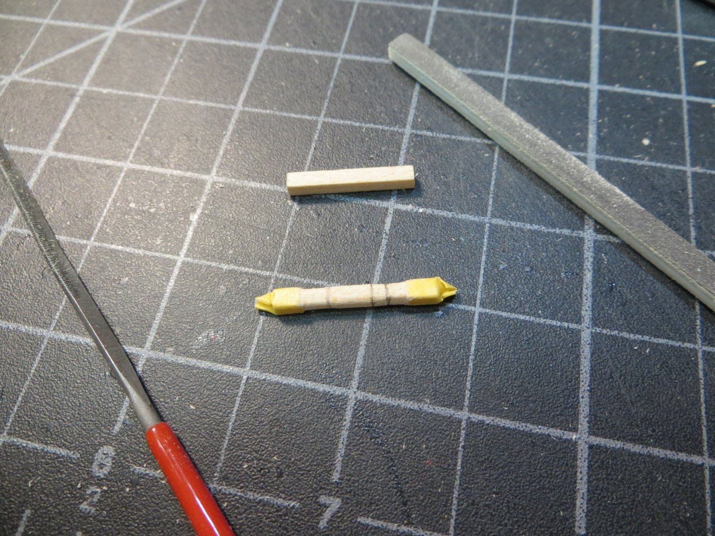
Gun Port Lids I made a decision way back when I was planking the hull that I was not going to cut out the gun ports on the quarterdeck or in the front of the bow. A closed gun port lid would hide the fact that there was no cannon behind it. I needed 10-gun port lids. Two of them would be open for the 2nd pair from the stem. I made the gun port lids using the wood sandwich technique I came across by “GTM of Copenhagen” on our site. In hindsight, this probably was not necessary because after I painted the lids, the seams between the planks were not very visible. This would work better on an unpainted model. Maybe on a future model! I made the closed lids 3/64” thick. The open ones are 1/16” thick with the interior side painted red. There are 2 lids per side at the bow and 3 each along the quarterdeck. Total of 10 required. I will air brush the outside of the lids with the same yellow ochre as the hull. I ordered two packs of 10 Mantua Brass Gun Port Hinges from Model Expo (MAN37360). These are 0.3 x 2 x 10 MM in size. The pack come with 10 hinge/hasps, 10 short brass rod and 20 brass eyebolts. The rod is supposed to go in the hole at the top of the hasp and the eyebolts go on either side to make a working hinge. I do not plan to make a working hinge, so I skipped the eyebolts for the rods. Construction Steps 1. Use a 1/16” x ½” piece of stripwood (#3624). Use the mini-plane to shave this down to 3/8” 2. Cut a long strip of cardboard stock with a 1/128” thickness to match the 3/8” width of the stripwood. This is supposed to simulate caulking. I used yellow because I wanted the lids to match the hull. This worked so well, you can't even tell I put in all this effort!! 3. Apply PVA glue alternating 5 layers of wood with 4 layers of card stock. I ended up with a 3/8” square. That’s not what I was expecting, but it will work! (I expected it to be less than 3/8” tall) 4. Use the mini-chop saw to cut off 10 slices 5. Air brush the lids yellow ochre to match the hull. Hand brush two lids with same red as inside bulwarks 6. Blacken the 20 brass hinges/hasps and rods. The brass rods did not blacken very well. I also did not like the look of a short rod in each pair of hinges on the lid. I decided to use a steel wire brad type nail of 5/128” diameter for a perfect fit in the hole for the hinge. I cut them to a length with wire cutters so they could span across the 2 hinges. I thought this looked better and was easier to keep squared up on the lid. 7. Use CA glue to attach the steel brad in the hinges to simulate a working hinge. Allow a bit to overhang on the outside of each hinge. Here are the parts ready to assemble. Then a completed lid. 8. Glue the hinges to the lids using CA. The completed set of gun port lids 9. I took 10 eyebolts from the kit to use for the rope that pulls the lid open. Blackened them. 10. Drill a pilot hole for the eyebolts on the lower edge of each lid. Glue them in place 11. I used Weldbond to glue the lids to the hull. I had to gently bend a few of them so they formed to the curve of the hull. 12. Tie a length of thread to the eyebolt 13. Drill a hole above the lid to pass the thread through the hull for raising the gunport lids. Use a drop of glue to hold these in place And finally here are the completed gun port lids! I am not going to attach the open gun port lids until I am done with the hull. I’ve read several build logs where these got knocked off with the handling of the ship. Hopefully the closed lids will be safe! Now that I have the gun port lids in place, my next step is to install the deadeyes into the channels and nail the chainplates underneath them into the hull. Thanks, Ed


-
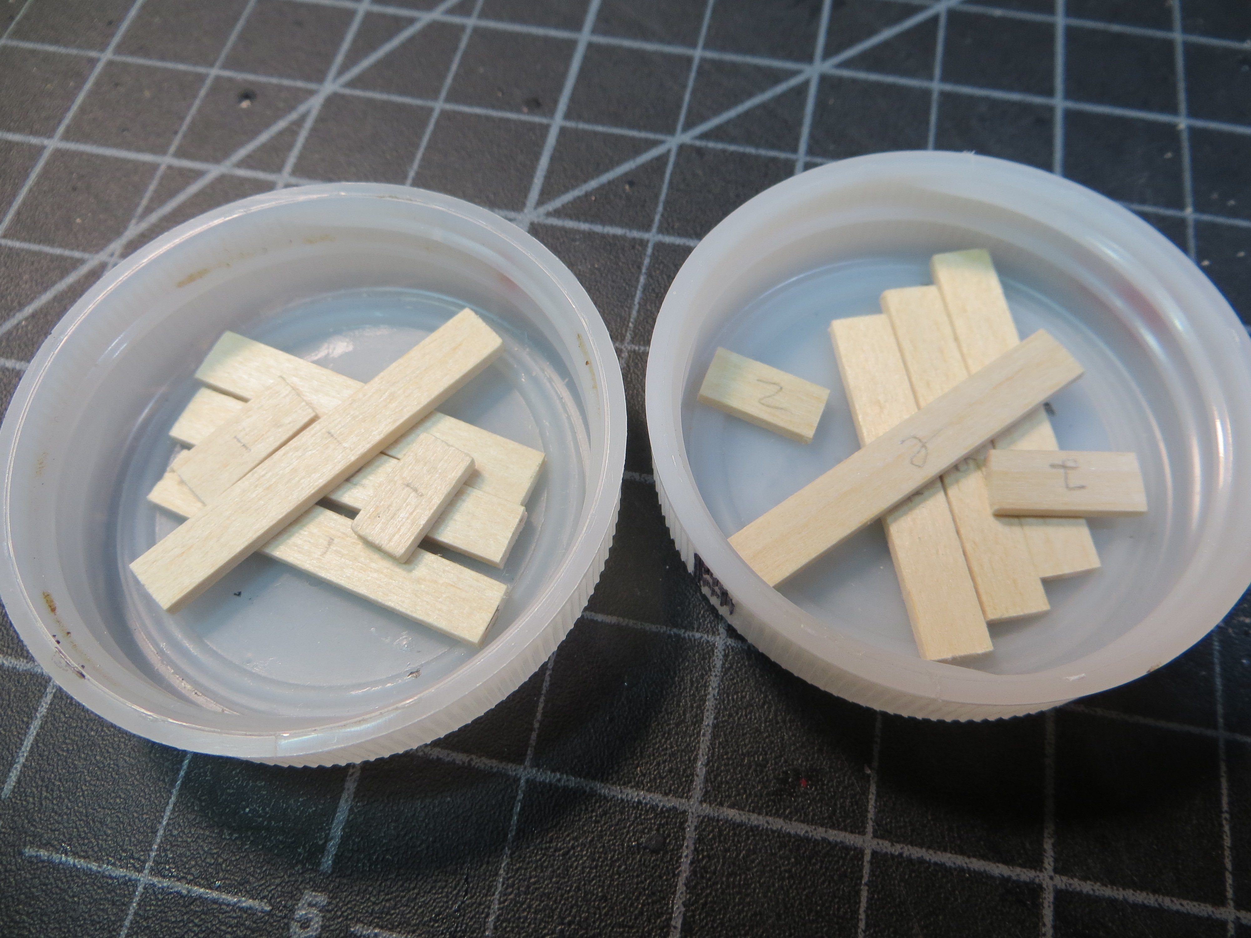
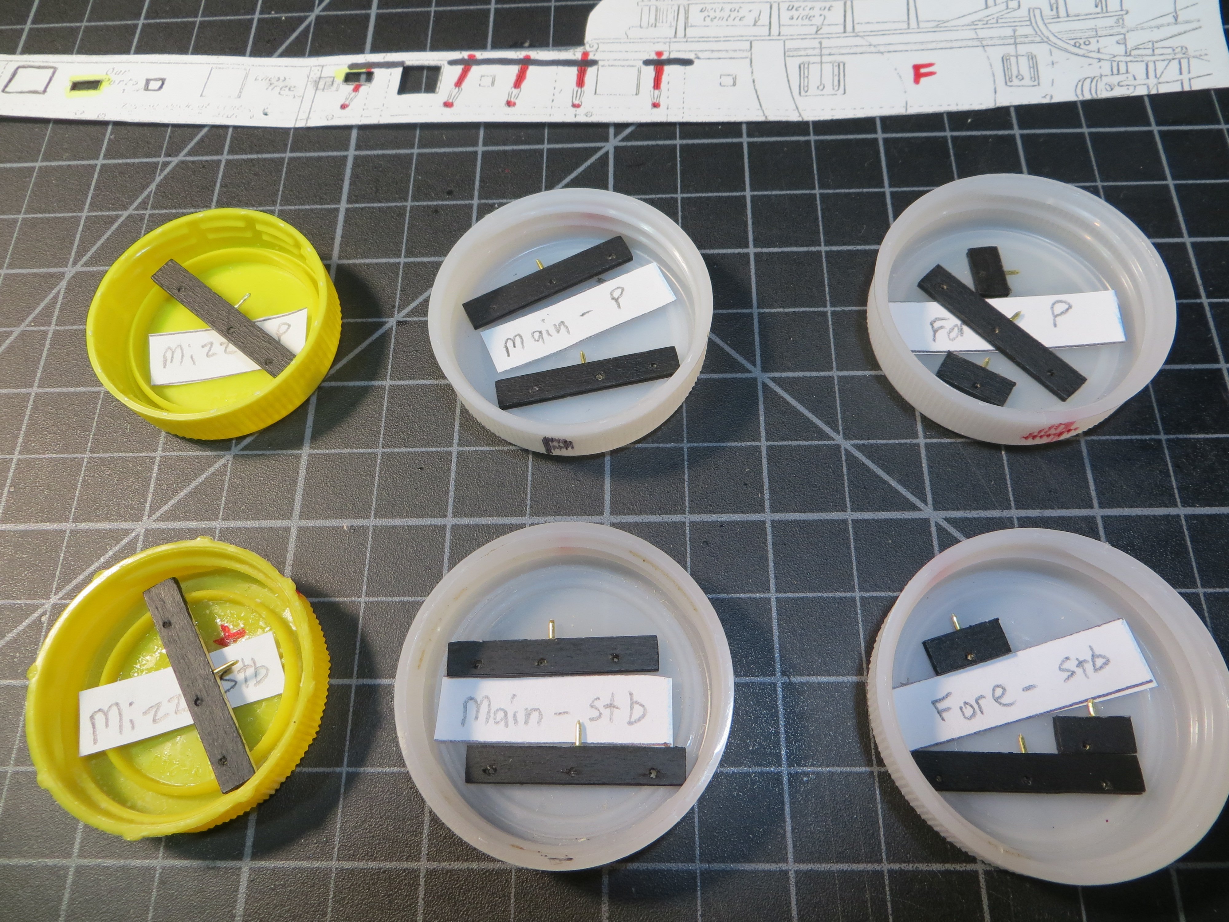
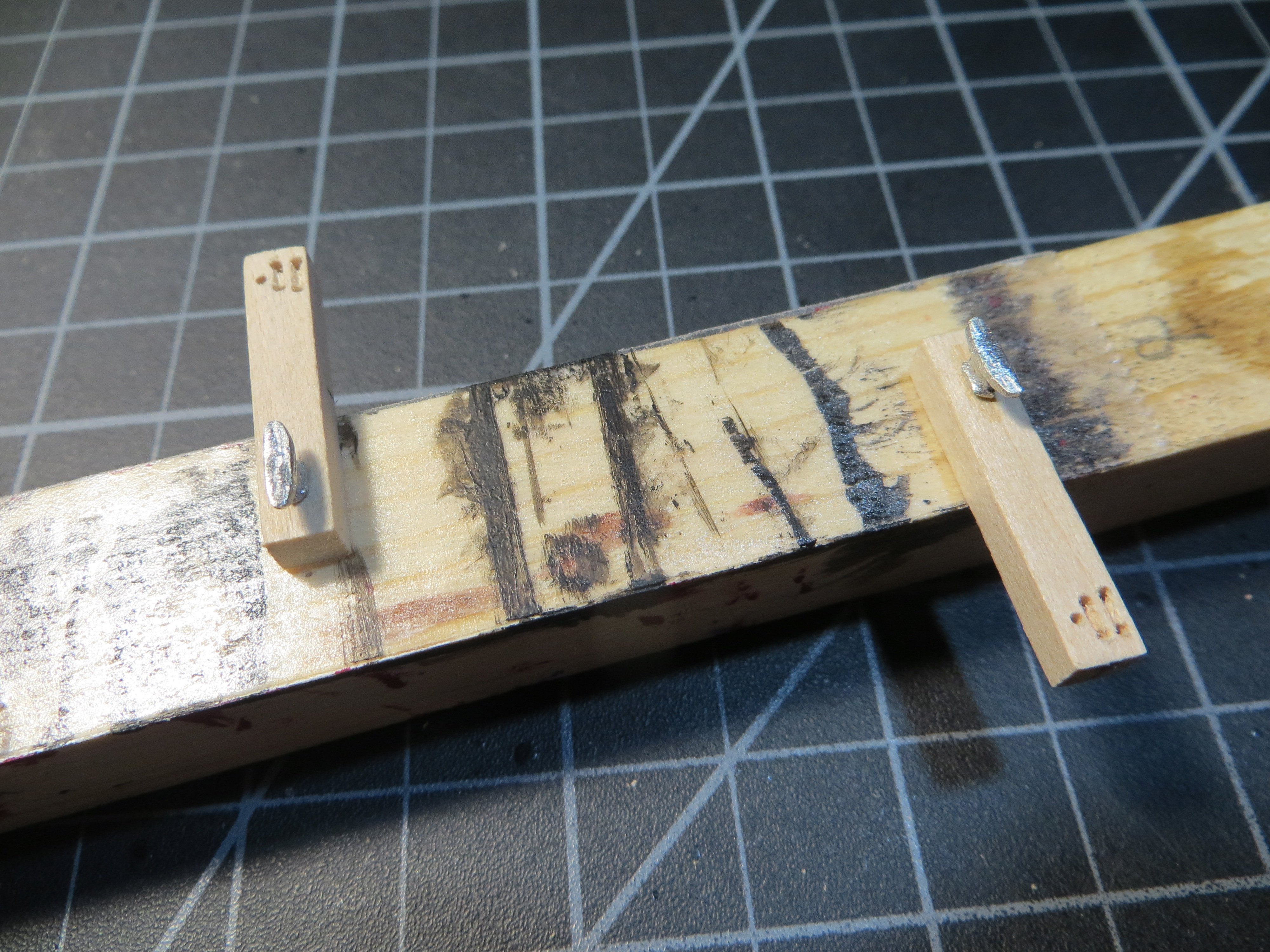
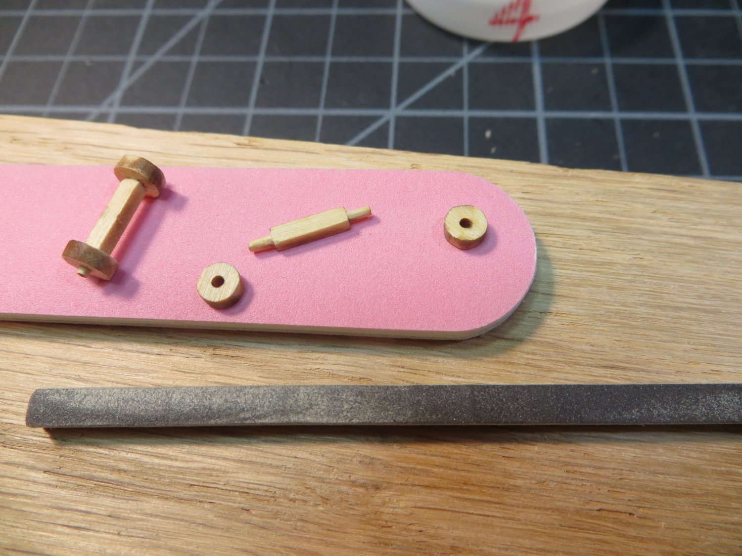
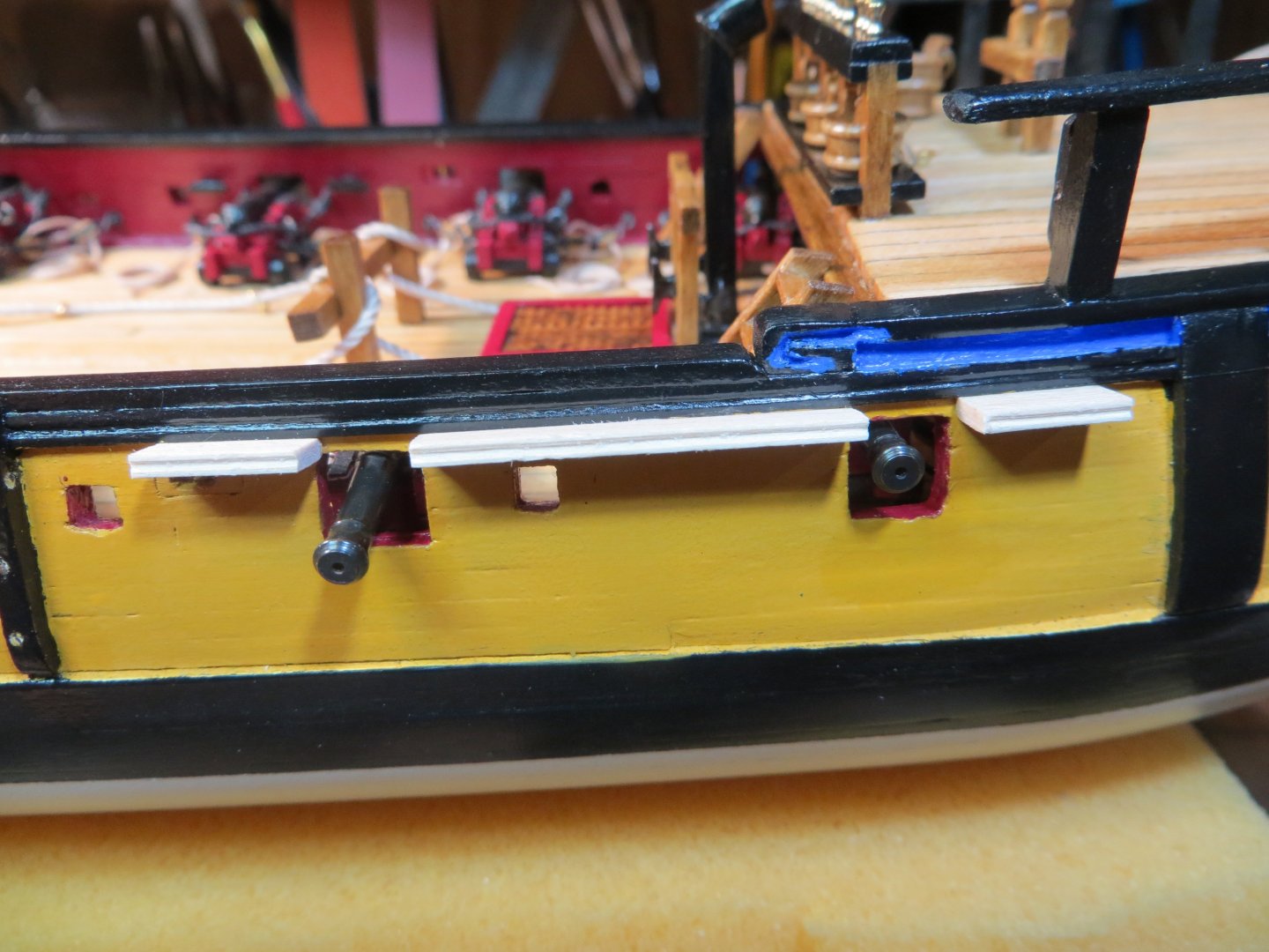
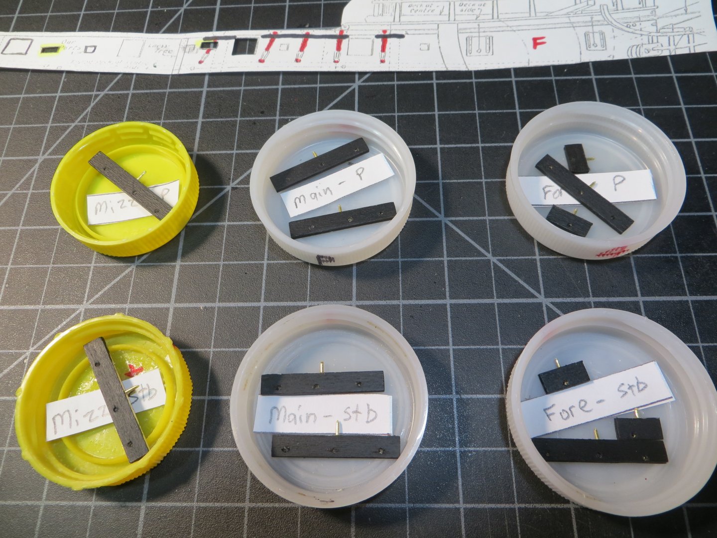
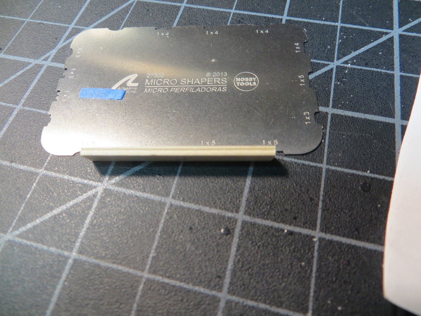
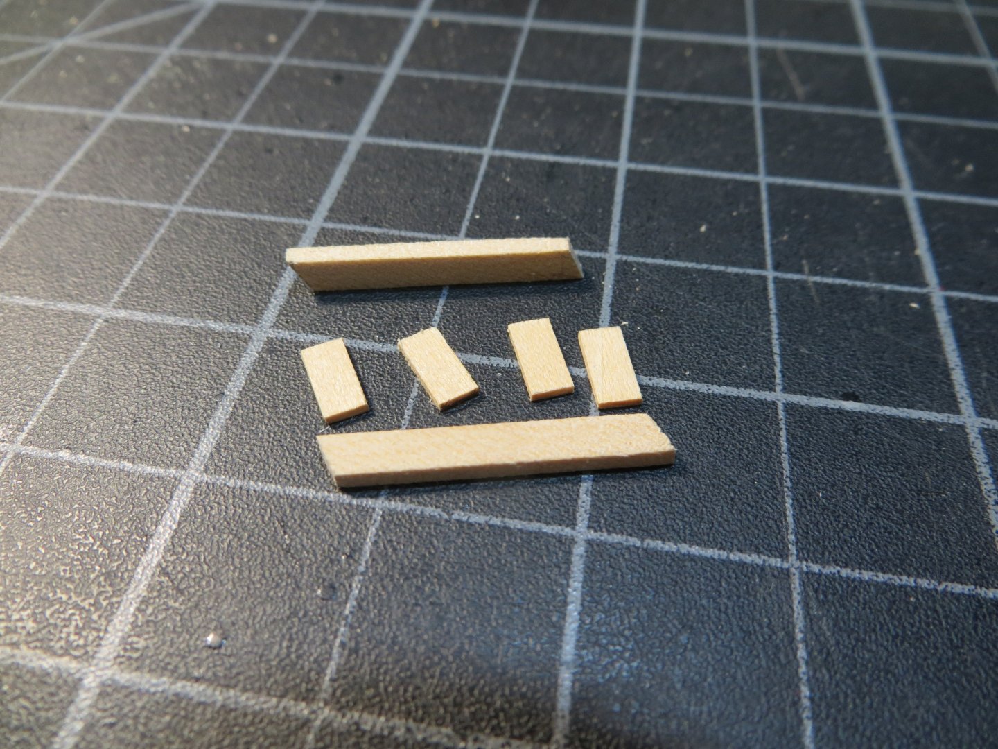
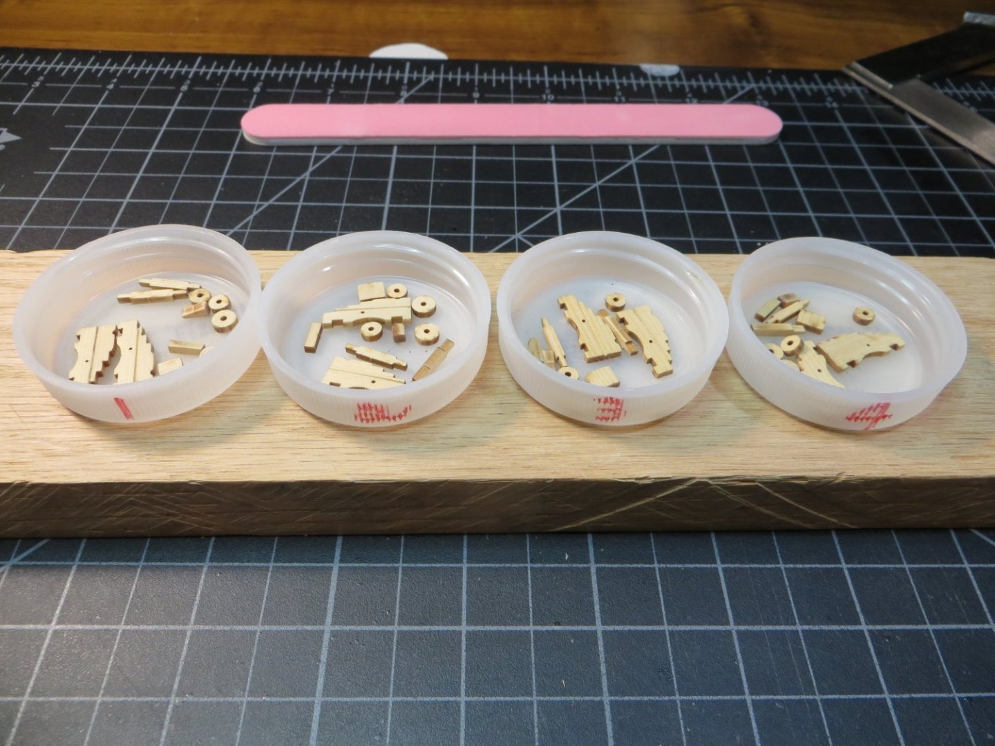
Channels My first build, the Bluenose fishing schooner, did not have channels. The deadeyes were attached through an overhang on the railing to chainplates on the hull. So, this is new to me. It seems to me that the installation of the Channels and the Gunport Lids need to be done together. The channels are positioned in between the gunports. The chainplates have to be positioned so they do not interfere with the gunports. The first step was to carefully measure and mark the positions for every channel and gunport lid. I used a cutout copy of the hull plan to locate these positions. I also marked the angle the shrouds take through the channels by using the nail point positions at the bottom end of the chainplates. There are 6 channels on each side. Gaps are inserted wherever there are gunports. The one exception is the aftmost gunport where the lid is directly under the channel for the mizzen mast. All the channels are attached directly under the molding strip. Using the plan blueprint, the molding strip covers about 3/64” of the channel and the plans call for 1/8” beyond that. So, I used 3/16” x 1/16” stripwood from the hull plank supply. All Channels cut and sanded. I separated them by starboard & port in bottle caps. I also numbered them by position I decided I needed to add a 0.032” brass rod pin in the center of each channel. I’m concerned about the small gluing area relative to the size of the channels and the stress of the shrouds. A hole was drilled into the back edge of each channel with a pin vise. I used the technique of inserting a very short test rod into the hole in the channel. This rod is sharpened to a point to mark the exact spot to drill the hole in the hull. This technique worked well for me. The holes for the chain plates should be made before attaching the channels to the hull. I read JSGerson’s build log. His instructions (Hahn build) called for a trim board to be attached over the edge of the channel to cover slots made for the chain plates. This cover board has a fancy edge like the molding strip. I simply drilled holes with a 3/64” bit about 1/32” in from the edge of the channel. I used the blueprints to line up the fore-aft position of the holes. Then I used my Artesenia shaper to put a fancy groove in the edge of each channel. The channels are painted with black acrylic paint before gluing them to the hull using PVA on the wood and CA on the brass rods. Here is the groove cut in the channel with the Artesenia shaper Channels on the starboard side for the fore mast are dry fit before painting All channels after painting and ready for gluing. Note the brass rods inserted on the hull side edge. The same completed channels after gluing to the hull I won’t nail in the deadeyes & chainplates until after installing the gunport lids. This will ensure that the spacing is correct. I’ll post more on this step later. I'm working on the gunport lids right now. Thanks for looking in! Ed

-
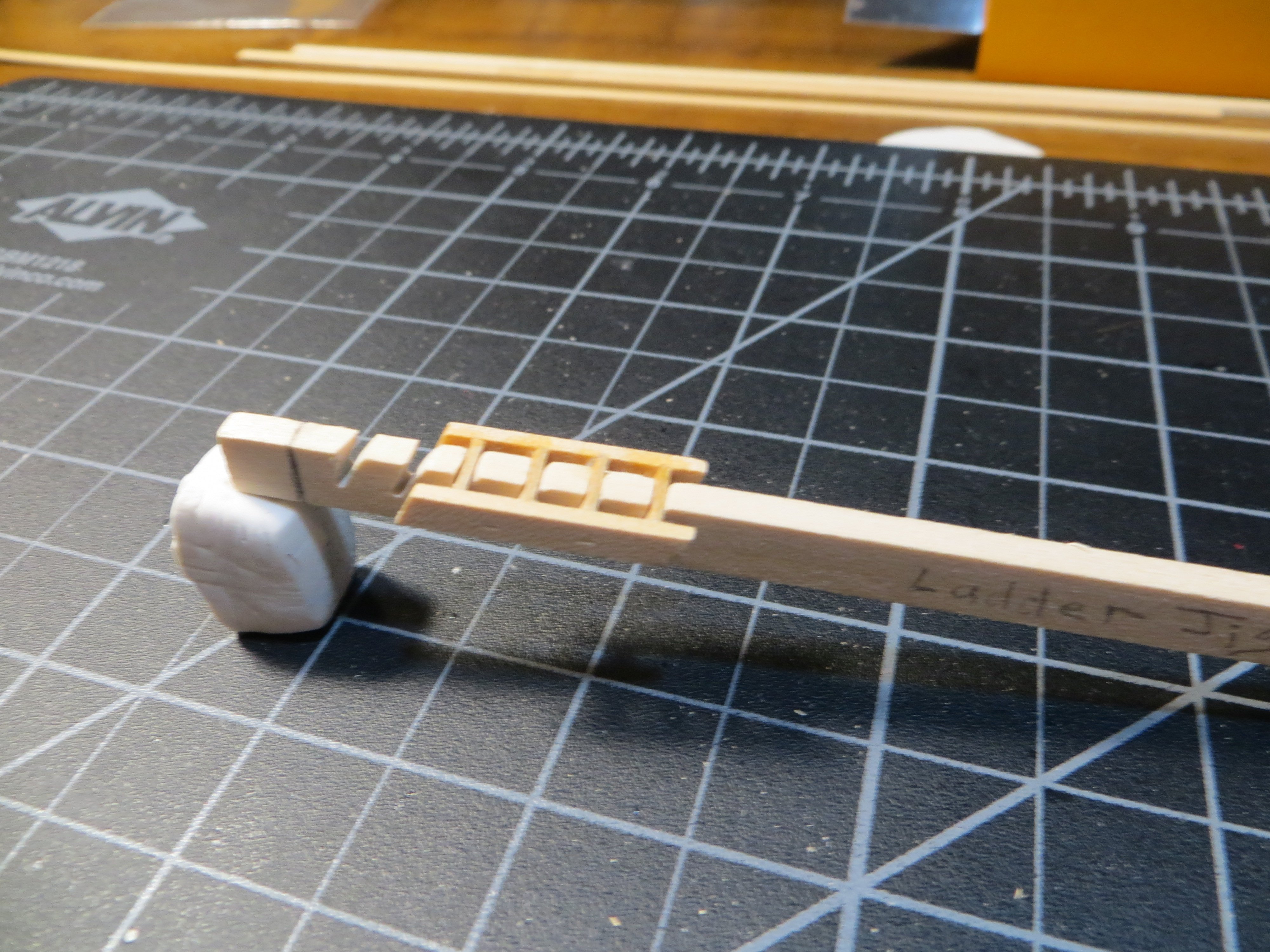
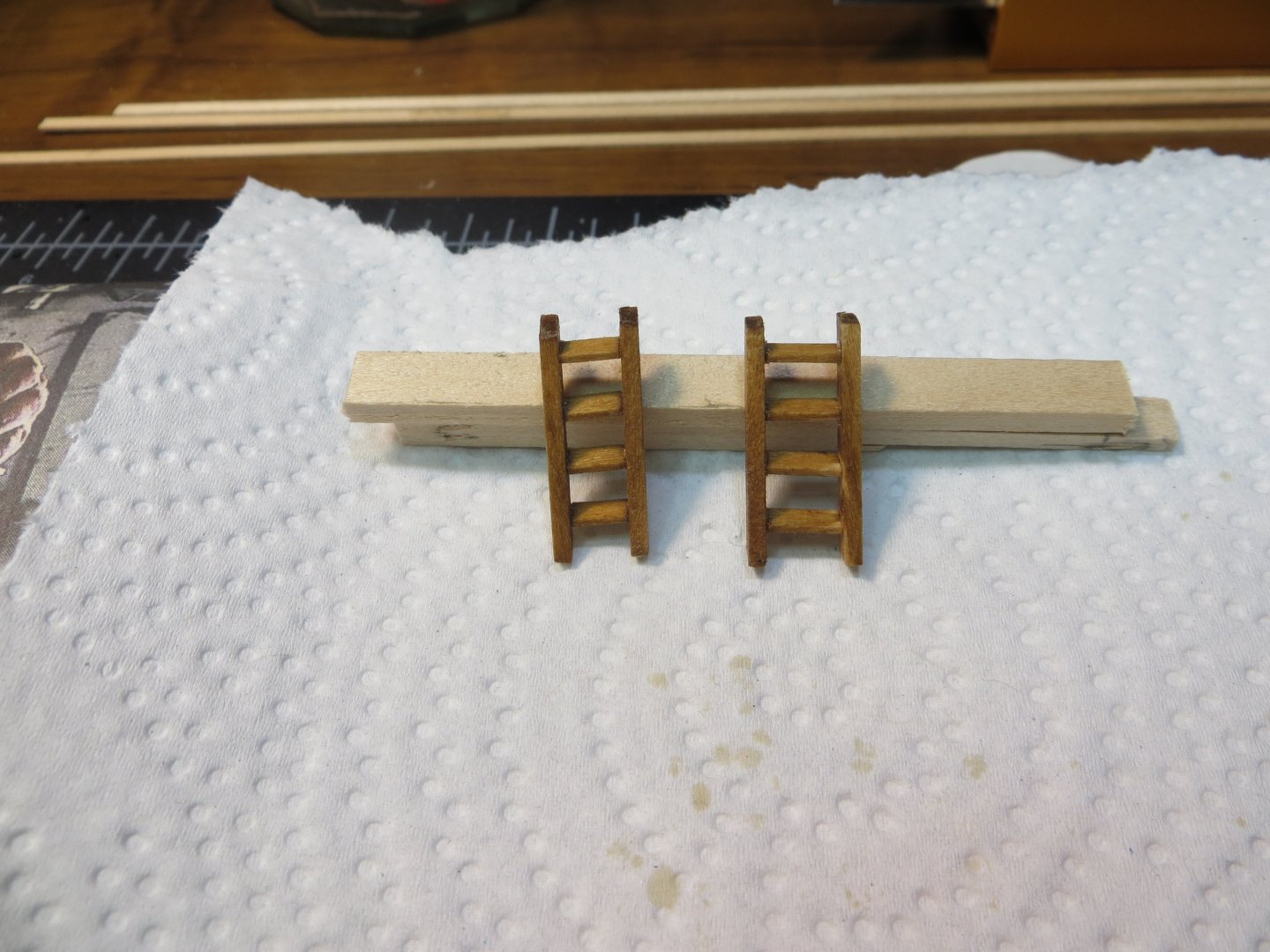
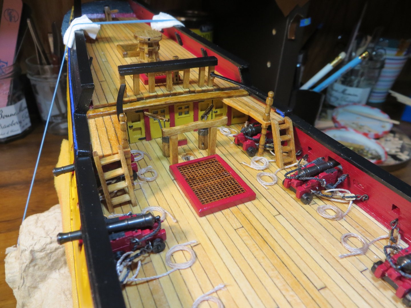
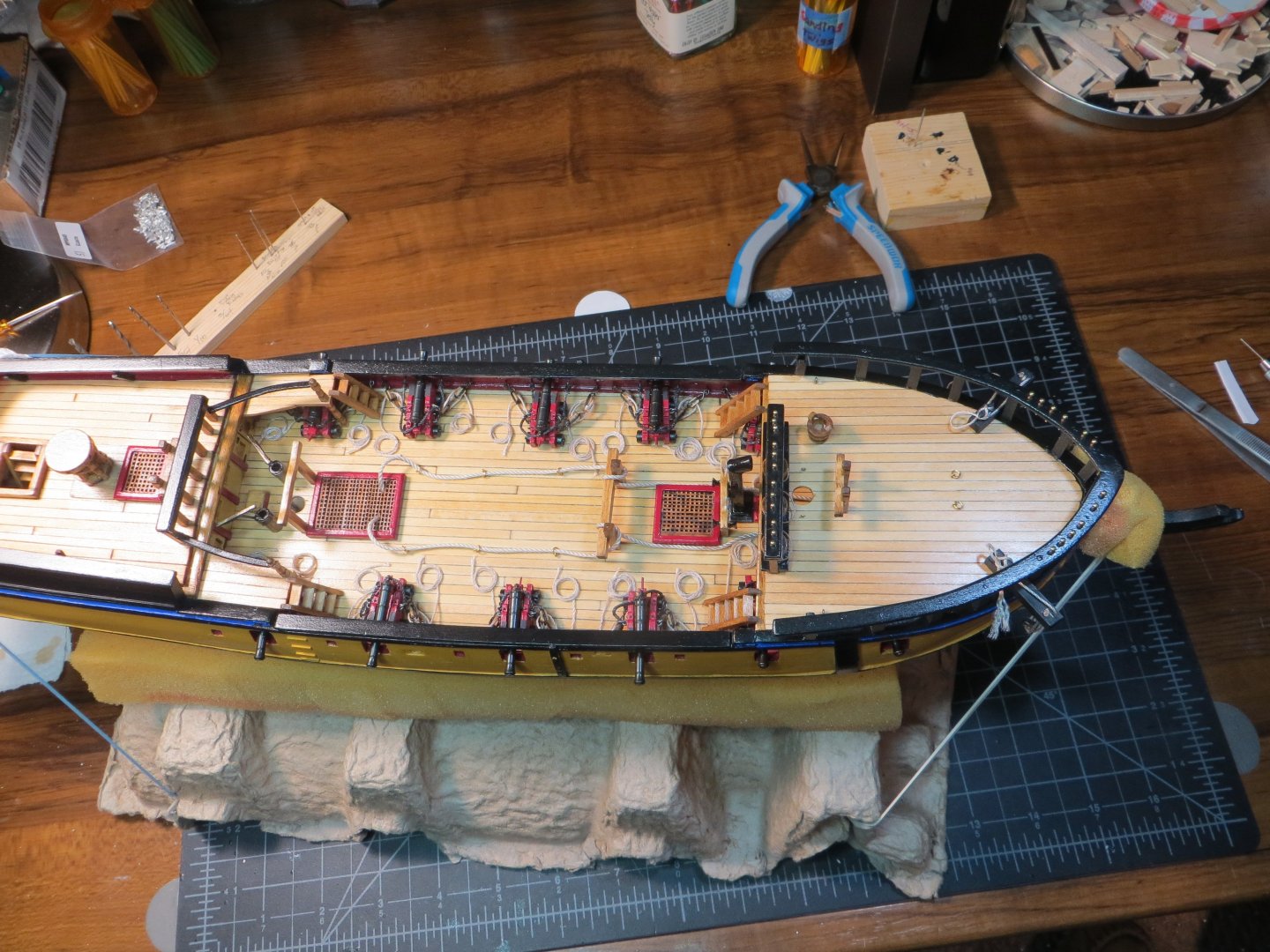
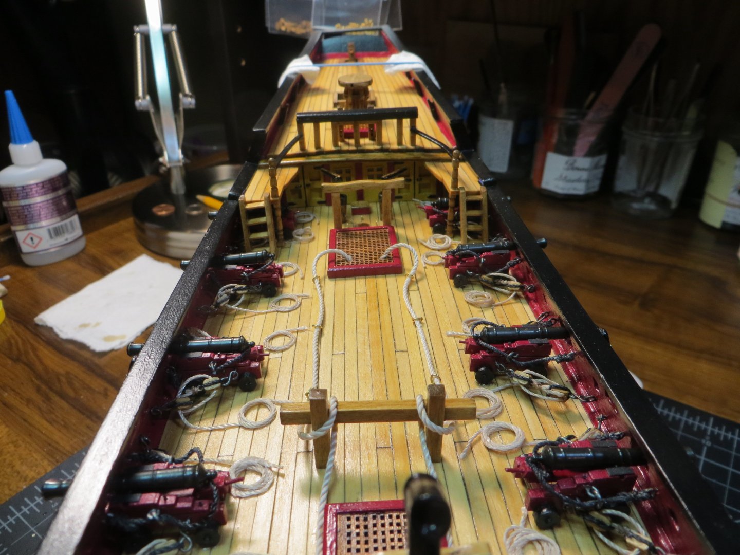
Deck Ladders / Anchor Cables / Catheads / Misc. Eyebolts & Ringbolts Deck Ladders Four ladders are required if you do not make the removable gangways. Two ladders are used to get from the gundeck to the quarterdeck. Two more are needed to go from the gundeck to the forecastle deck. I used the same ladder jig that I created in post #155 for the quarterdeck ladderway. I started with the q-deck ladders. I measured the height and width for the space. The starboard and port sides are slightly different. Port is narrower! An angle of 63 degrees is typical, according to my research. Four treads (stairsteps) are required for these. The stiles are cut to a 63-degree angle. Here are the cut-out pieces ready for the jig The treads are arranged in the jig and then the stiles are glued to each side Stained with Minwax Golden Oak Glued in place. I should have accounted for the camber of the deck with the stiles! Anchor Cables According to the plans the anchor ropes or cables are 3-1/2” in diameter. At model scale this is almost 1/16”. The heaviest rope in the kit is the 0.04” Manila Hemp that I planned to use. This is a little smaller than 1/16”, but I’m going to use it anyway! I blocked off access to the rope holes in the bow with my “manger board”. I knew this at the time and planned to fake it with separate pieces of rope on each side. Six ringbolts are used to guide the rope along the deck. The plans show the ropes looping around the heavy wooden riding bitts before disappearing under the focsl deck. The rope also “disappears” into the large hatch on the gundeck. I used a few dabs of gap-filling CA glue to hold the ropes in position. View of the anchor cables looking aft View of the anchor cables looking forward Catheads The Catheads hold the anchor when it is not being used. These are a pair of heavy timbers that overhang from the focsl deck. According to the plans the timbers are to be 5/32” x 3/32”. No such size is provided in the kit. The closest piece of stripwood I have is 3/16” square which was left over from my Bluenose build. I sanded this down on the bottom to reduce the height by 1/32”. It doesn’t appear to me that it looks out of scale. It took me a while to wrap my head around the rigging that needs to be attached. It didn’t take long to decide that I didn’t want to add the Cat Stopper! Different sets of instructions call for anywhere from a single to triple block to be rigged. The consensus (and the one that made the most sense to me) was a double block. I inserted a brass pin in the deck end to secure it in place when gluing. I still need to make the anchors themselves. Five holes were drilled for rigging. The two pairs are connected to simulate pulley wheels. Cleats are attached. A double block is stropped with a hook. I left some excess rope at the end until the anchors are attached. Miscellaneous Hardware At this time, I also added a few other items on the focsl deck. The two extra Kevels I made a long time ago were attached to the inside of the end stanchions. Belaying pins were added to the railing and a pair of eyebolts and ringbolts into the deck. Birdseye view of the Gundeck & Focsl as of today Next steps include adding more miscellaneous hardware to the quarterdeck. Then the final steps: Head Rails, Gunport lids, Figurehead, Channels and Anchors are left to do. Also, the Ship’s Longboat, before masting & rigging can begin. On October 8th I will reach the 2-year mark on this Rattlesnake build! Best regards, Ed


-
Hi Gregg, I'm glad you found that post. I was going to point that out for you, but you beat me to it. To answer your question, I used the Model Shipways supplied rope. They call it 0.021" Diameter Manila Hemp. It's part number WP1242. I consider it a medium weight rope. It took me a while to finally come up with that jig. I've seen other jigs for rope coils, but this one works well for me. Ed
-
Hi Dave, Thanks for the kind words! I purchased the practicum from Lauck Street Shipyard called "Junior Course for Rattlesnake Masting & Rigging". Based on my early research rigging this ship is pretty complex. I'll let you know if this info is worth the purchase price once I get into it. Are you ever planning to get back in the shipyard to finish your 'Snake? Hope you are doing well. Ed
-
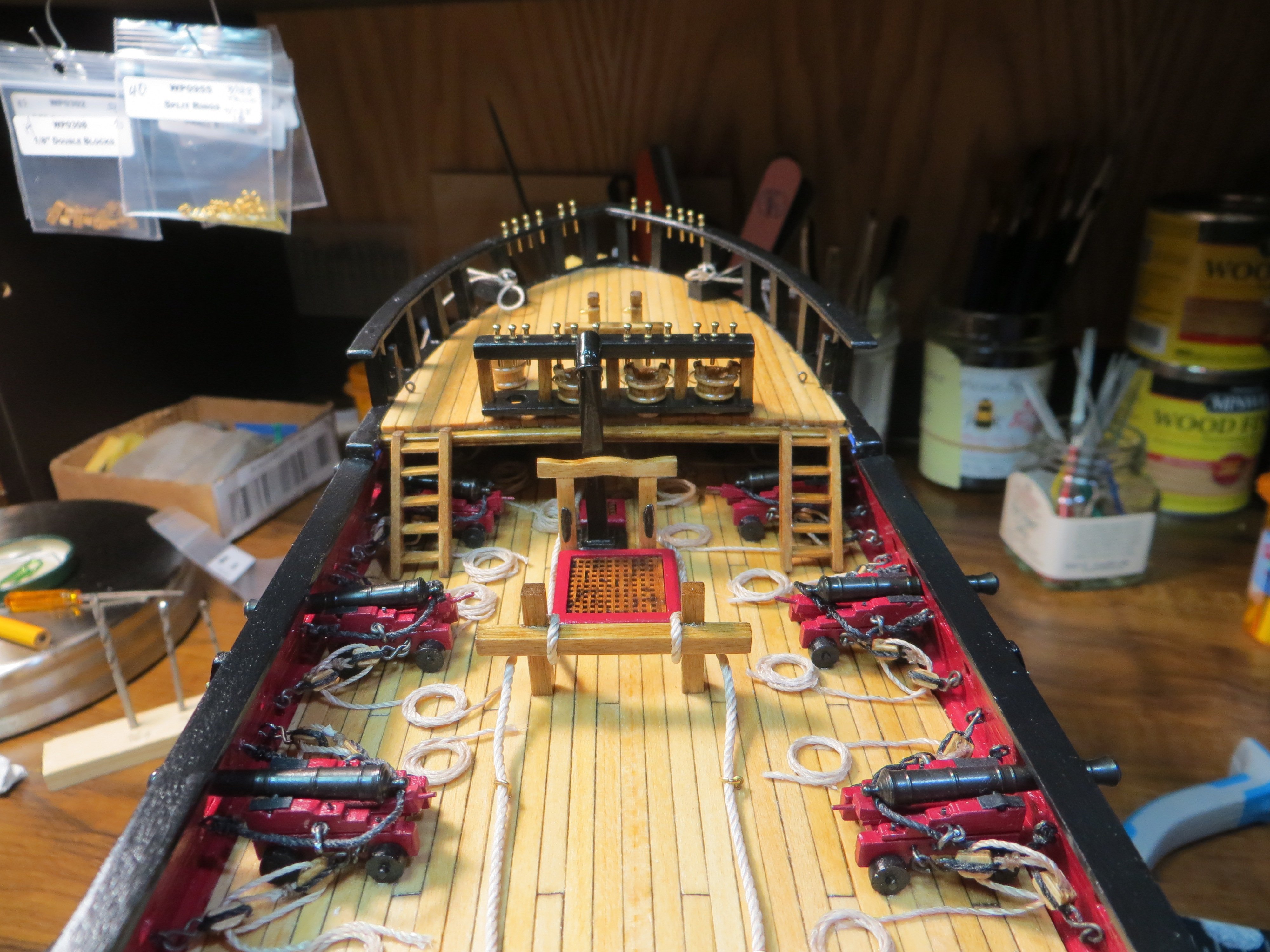
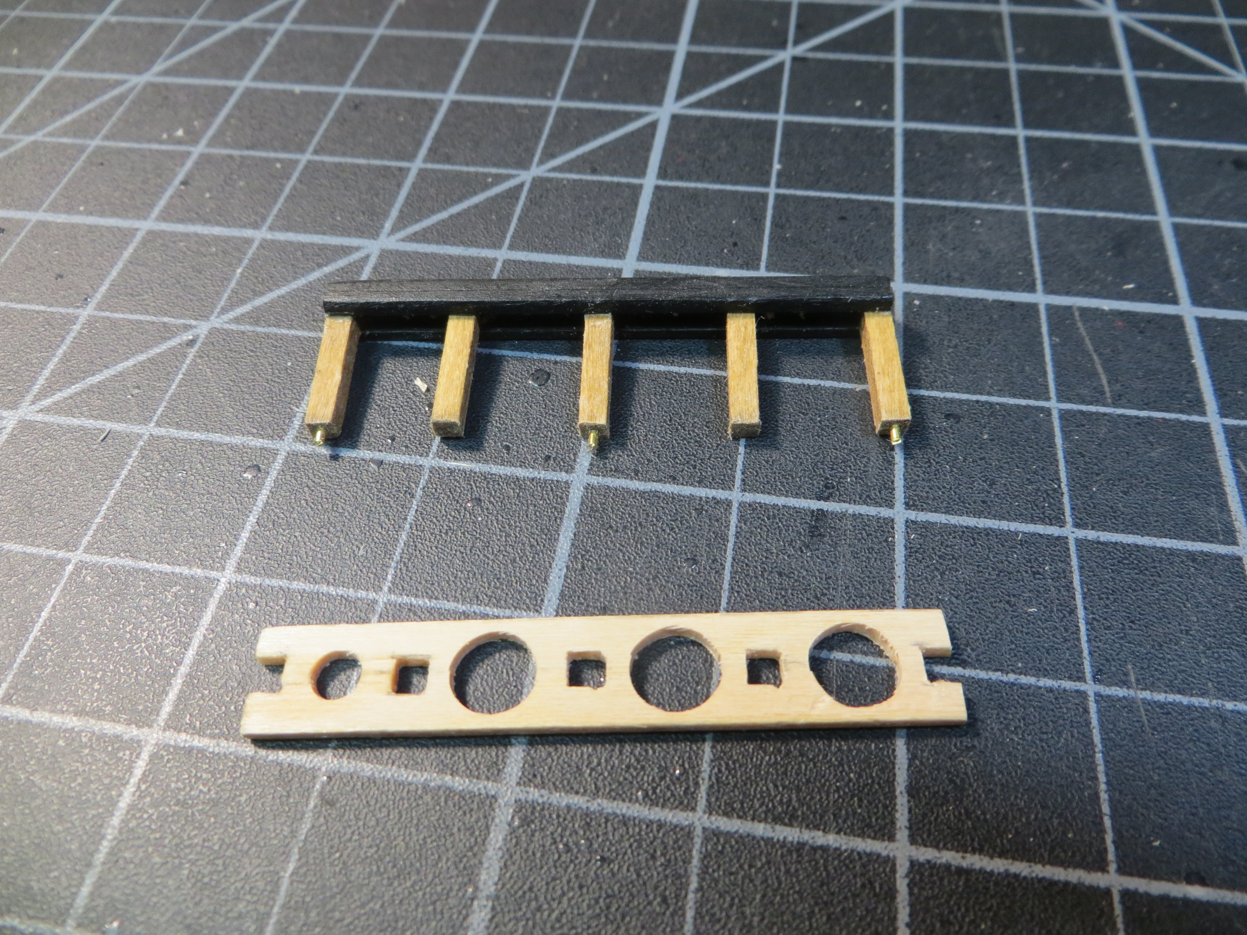
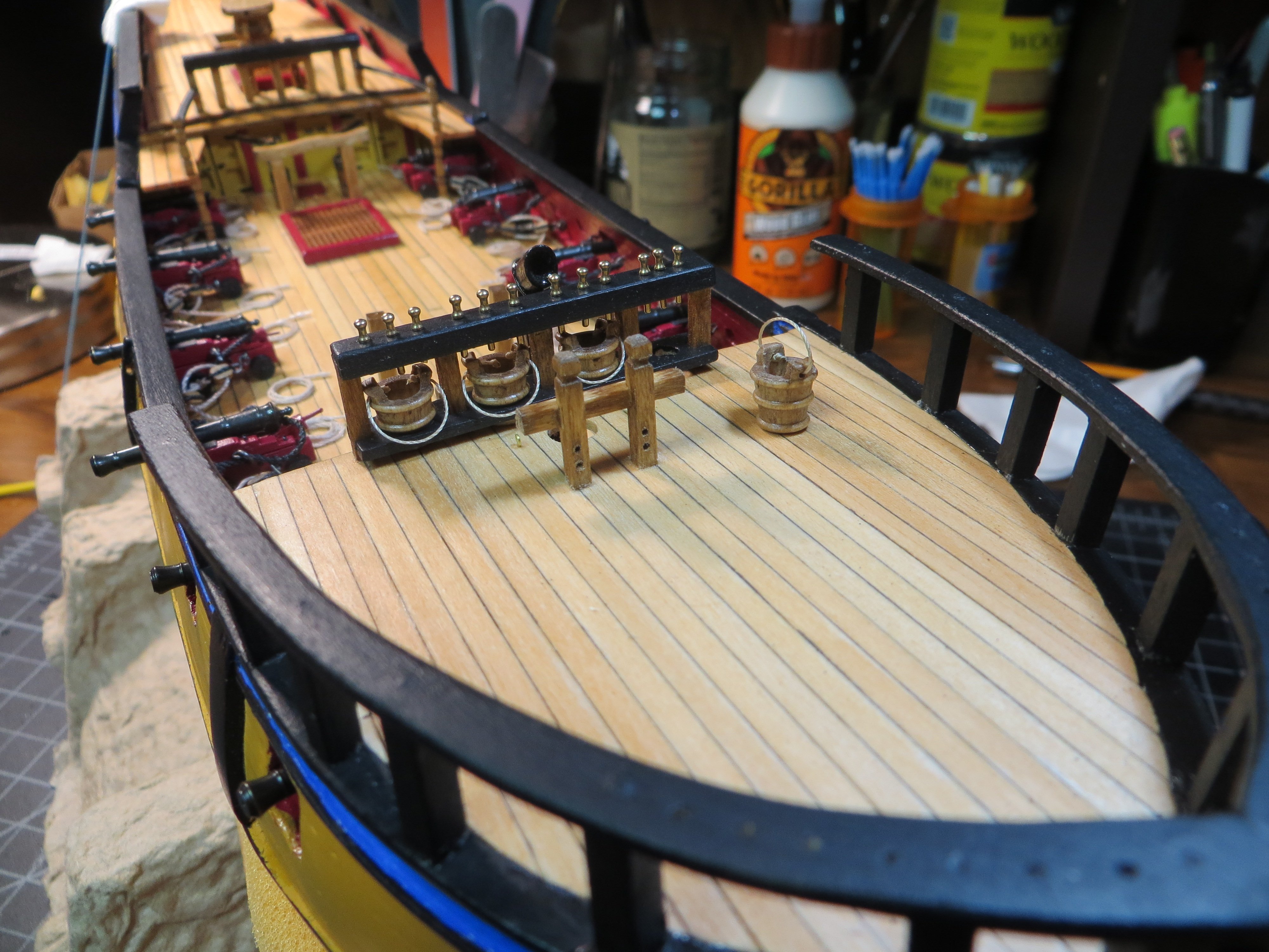
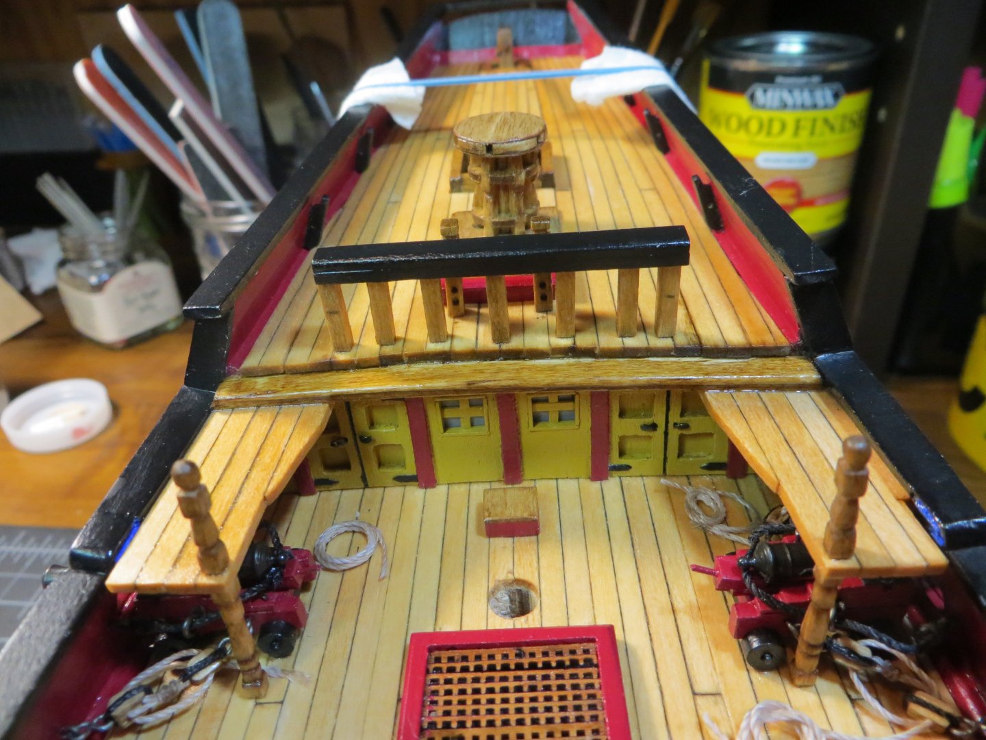
Forecastle Breast Rail I made the focsl breast rail with the same design as the quarterdeck fore rail. There are some differences between the two. This rail has a shelf or rack that is used to hold buckets. In order for the buckets to fit between the stanchions you need to reduce the number of stanchions from 7 to 5. The rail is fitted with 12 belaying pins, according to the plans. In an earlier post I asked the question, why do some builders place the buckets on the q-deck rail instead of the focsl, as indicated in the instruction manual? If I had to do this step over I would do it different. First, I would have placed the buckets on the q-deck rail. Second, I would have made the stanchions a little taller. The reason being that the focsl breast rail is too crowded with the buckets plus the belaying pins. My buckets were a bit too tall for ½” stanchions, so this required some adjusting. Or else I should have purchased smaller buckets! But supposedly, these fit the scale. Oh well, I made it work. I had one issue with the construction of the bucket rack. I used 1/16” thick sheetwood. As I was cutting out the last hole for the bucket, the board split on a line right down the middle along the grain. Between the holes for the stanchions and the buckets to fit through, there wasn’t much wood left to reinforce the grain. I was able to glue it back together with PVA, but decided not to continue drilling that last hole. I will just stand this bucket on the deck like it was being used by one of the sailors! When you encounter issues, you must get creative! I am not going to show pics for making the rail, since I covered this with the q-deck rail in post #189. Here are my build steps with a few pics. 1. When I cut stanchions using 3/32” square stock for the q-deck, I also cut 7 more for these. I only ended up using 5 of them. Insert brass pins in 3 of them for the center post and both ends. 2. Make the breast rail. Cut a 3/16” x 1/16” piece of stripwood at 1-15/16”. Cut 2 pieces of 1/16” square stock the same length. Glue the pieces to form a U-shaped channel. 3. Sand the assembly to 1/8” tall to accommodate the belaying pins later. Round off the top edge. Hand paint it with Vallejo black acrylic. 4. Mark the positions of the 5 stanchions, after staining them Golden Oak, do a test fit and adjust the stanchions for deck camber. 5. Drill holes in the rail for the belaying pins 6. Glue the stanchions in position. Make sure they are square to the rail. Spacing the stanchions evenly is important. 7. Cut an appropriately sized piece of stripwood for the bucket rack. Make square holes for the stanchions by standing the assembly on the rack/shelf. Drill/file holes for the buckets in between the stanchion holes. This is when I split the entire piece down the middle! Note that the round hole on the left side is smaller! I was afraid to take off any more wood. 8. Tie ropes to each bucket and glue them in their place on the rack. Glue the bucket rack in position on the stanchions. I kept the rack as close to the deck as possible as I did not have much head space above. 9. Mark the position of the assembly on the deck by pressing the pins gently into the deck. Glue it in place. 10. I also glued the Topsail Sheet Bitts in front of the foremast hole. 2 eyebolts were also placed in position on either side of the foremast according to the plans. Here are a few pictures showing the forecastle deck and the entire deck at this stage in the build. I hope this information is helpful to others building the Rattlesnake. My next steps are to work on the Catheads and also build the ladders to the gundeck. Thanks, Ed


-
Gregg, I actually used an Amiti Keel Klamp on this build up until about post #80. I had the ship turned upside down while planking the hull and I snapped one of the bulkheads in half at the clamp when pushing on an especially difficult plank! I messed up the hull pretty good and had to do some major repair work. I switched over to the cardboard wine bottle packaging and haven't switched back. I added the foam pad after the hull was painted. This rig keeps the ship closer to the desk and I've gotten used to doing it this way! Thanks everyone for your feedback! Ed
-
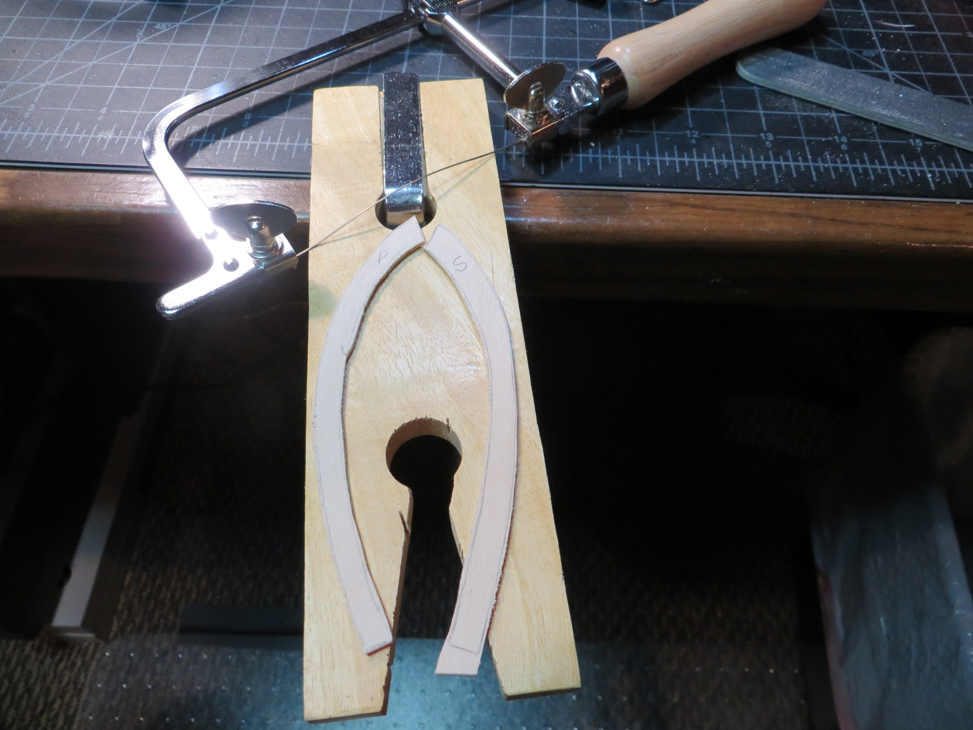
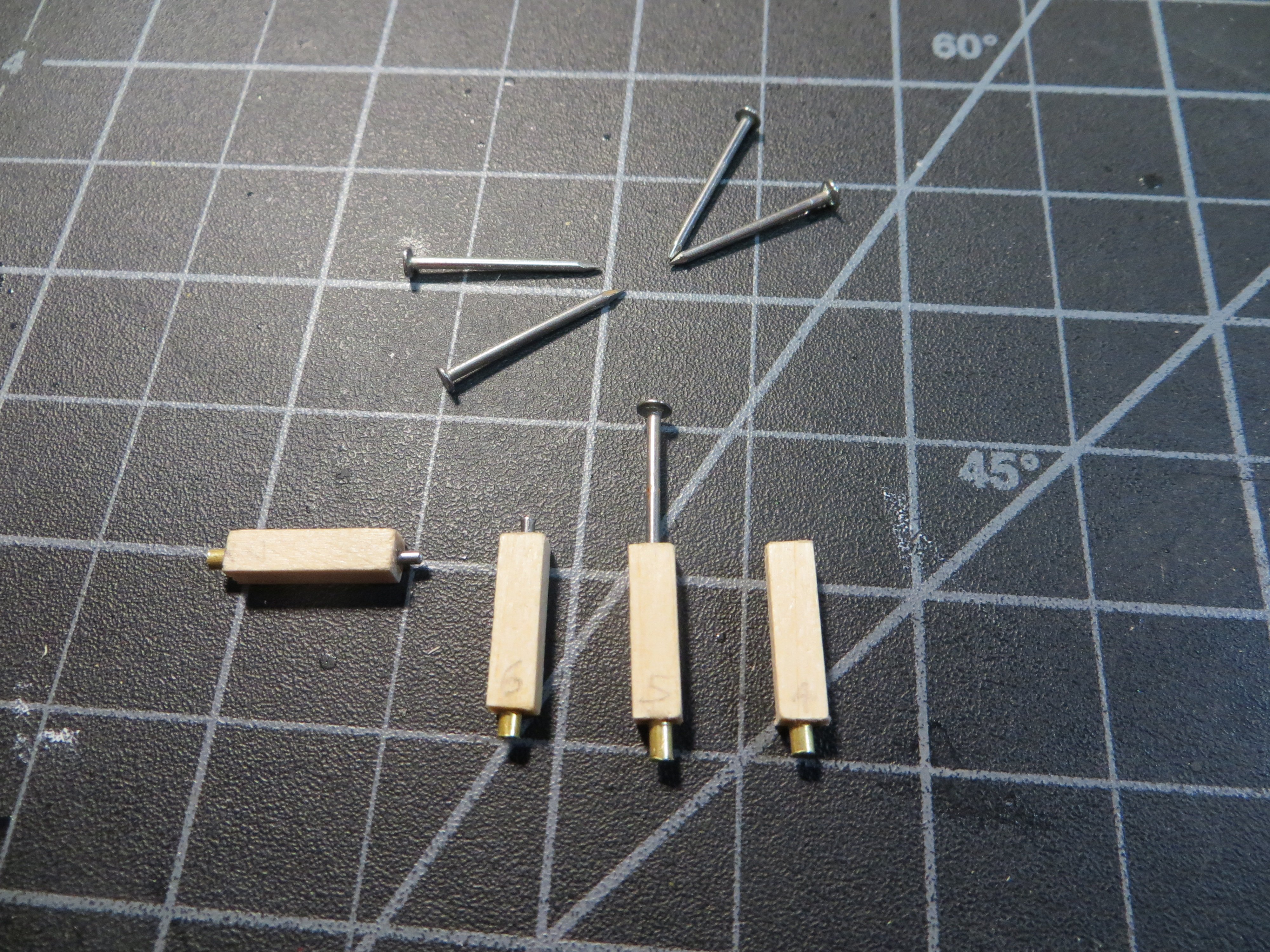
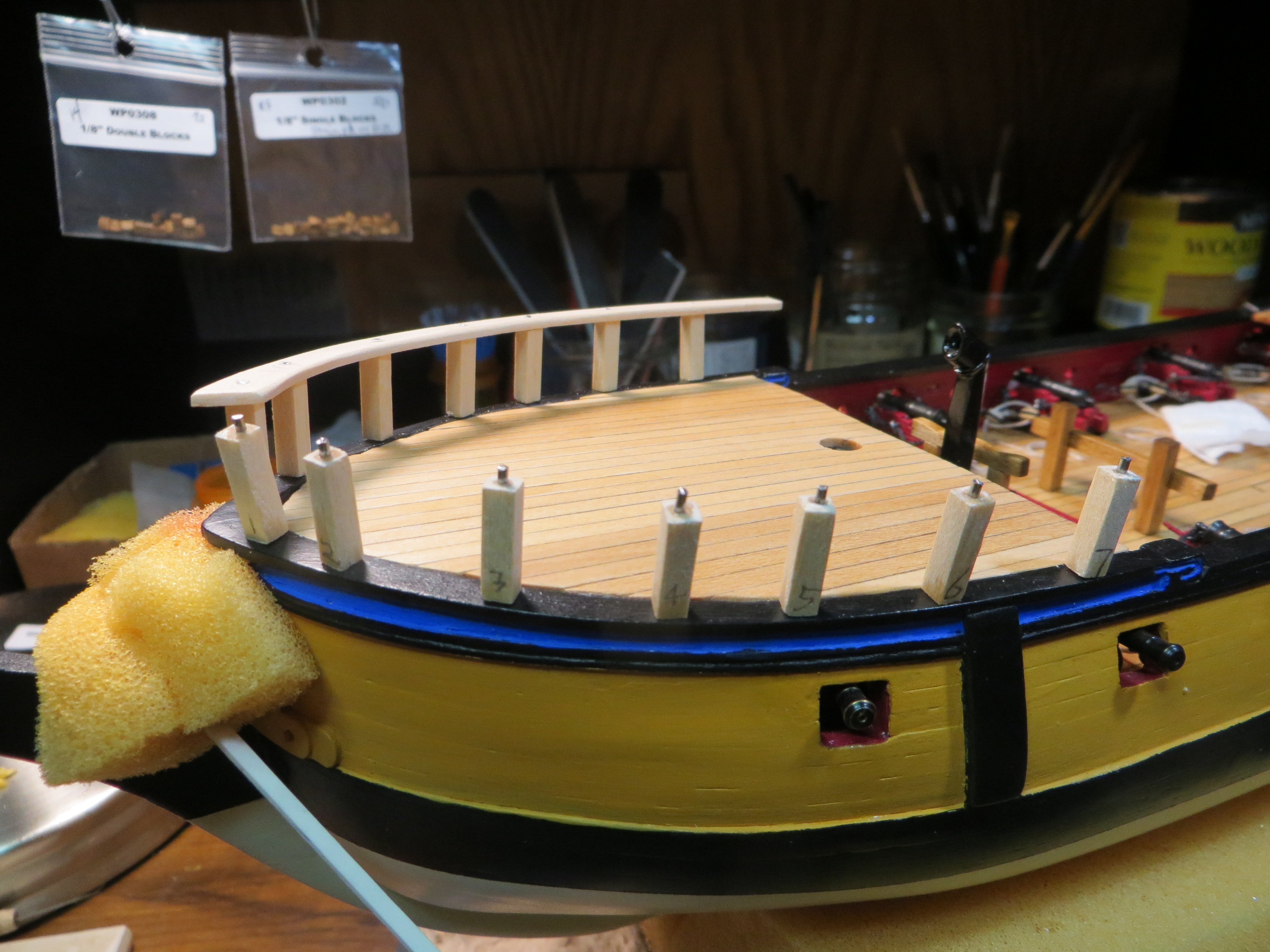
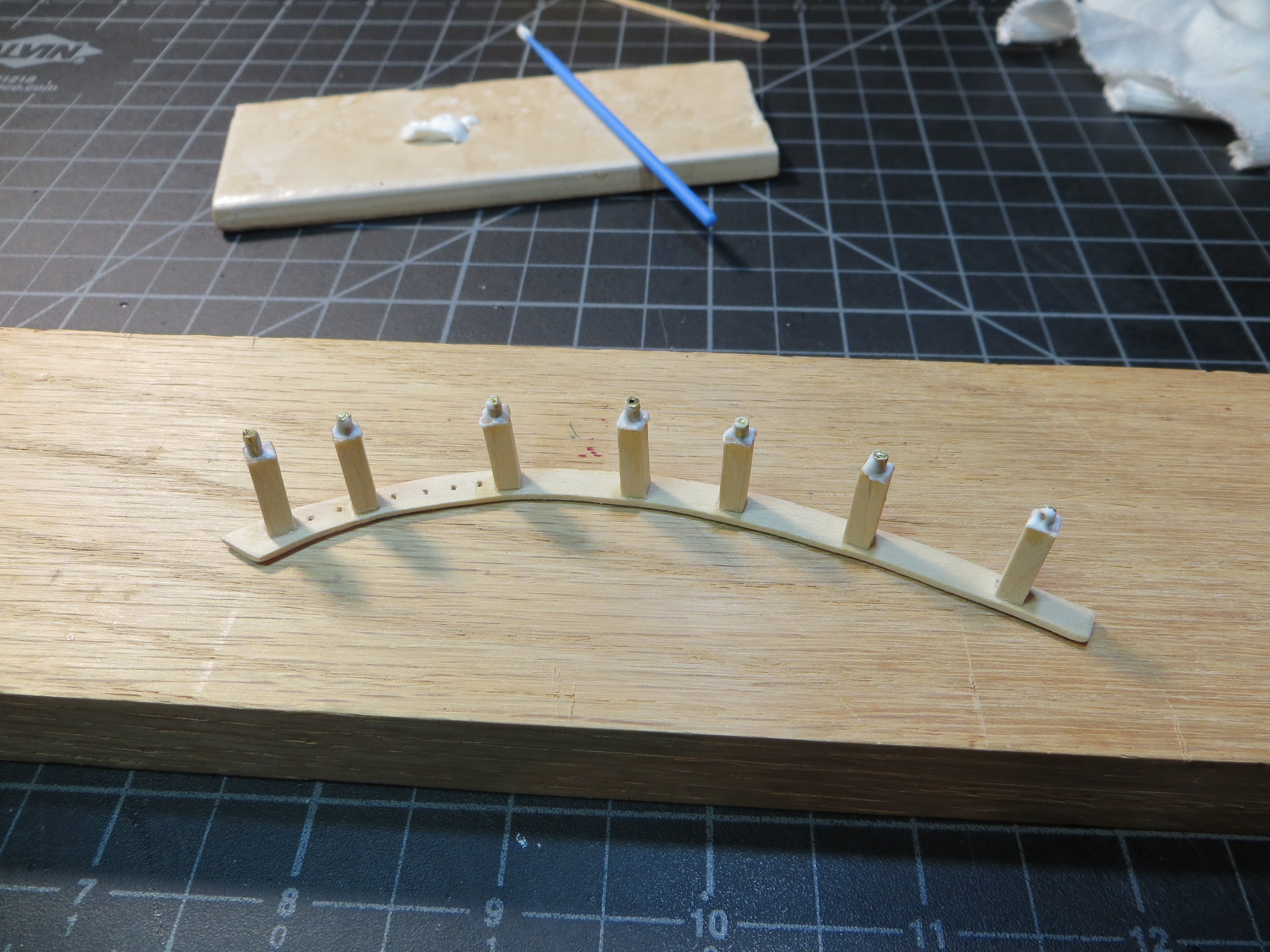
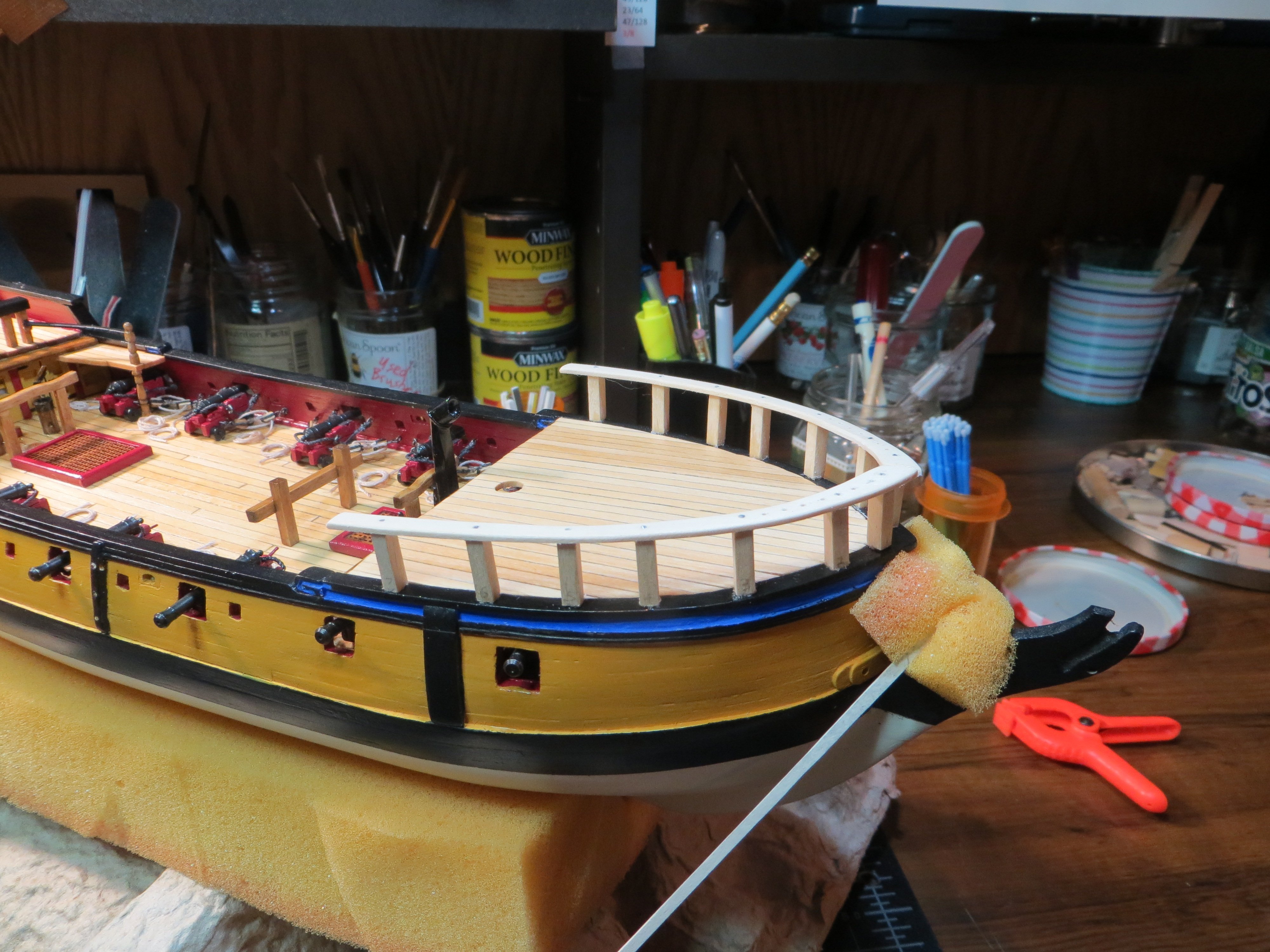
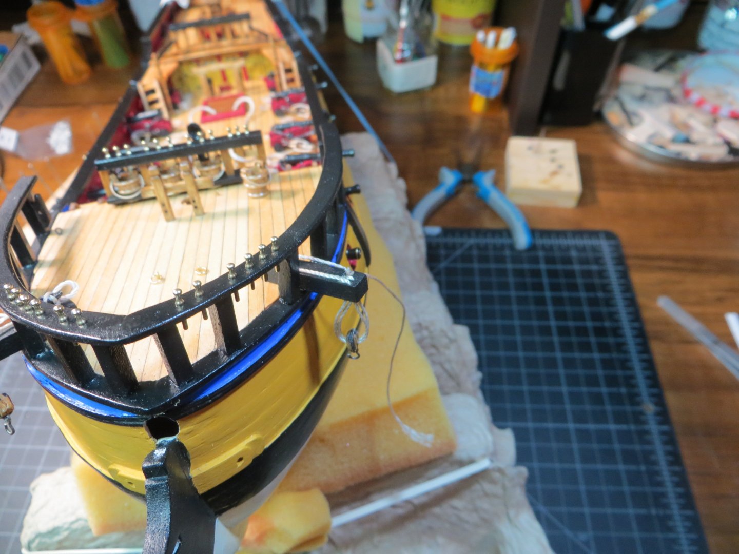
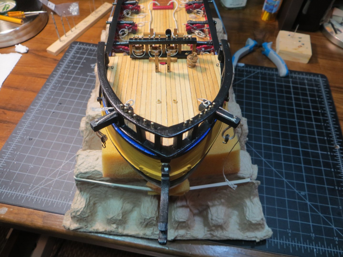
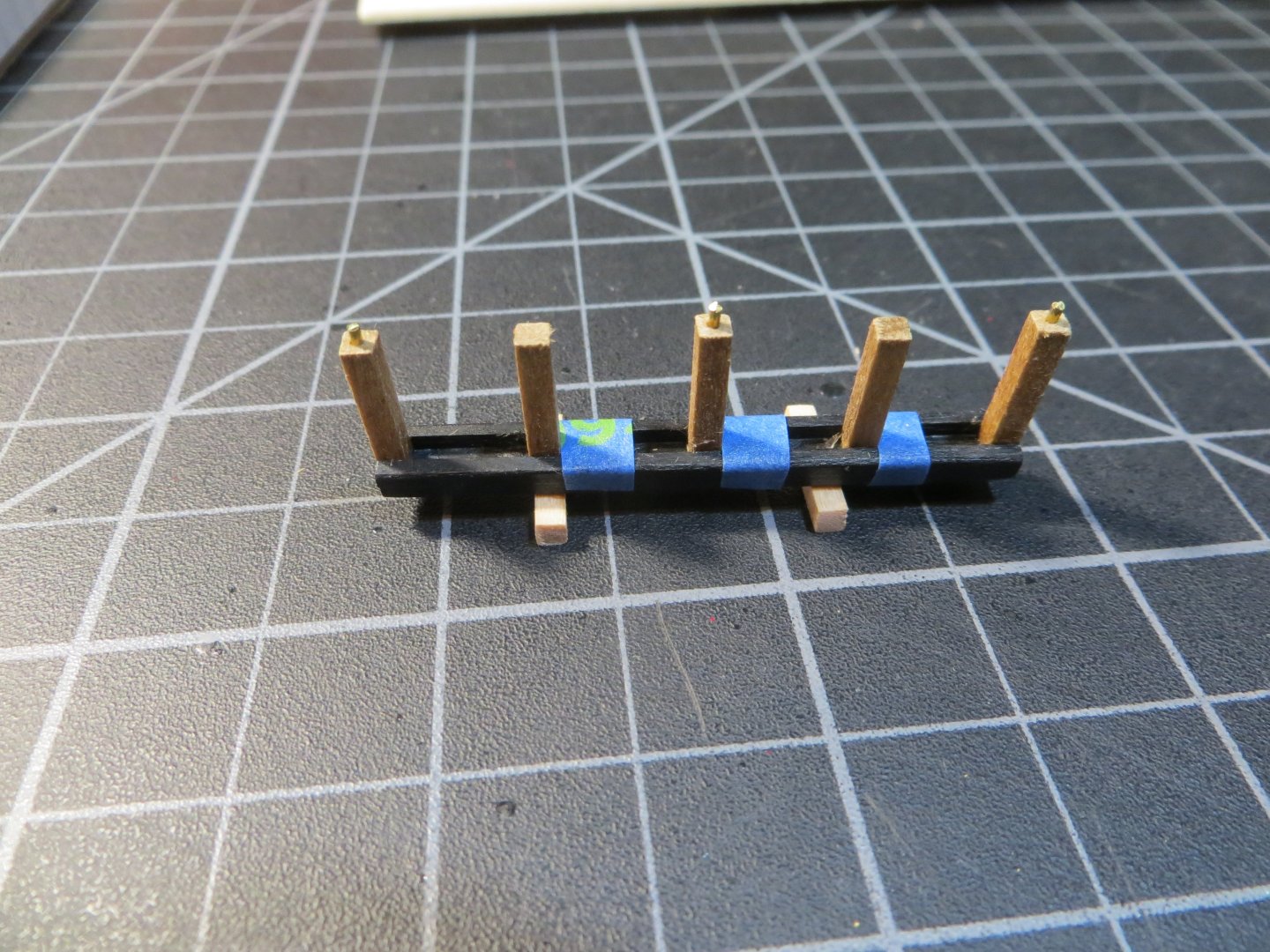
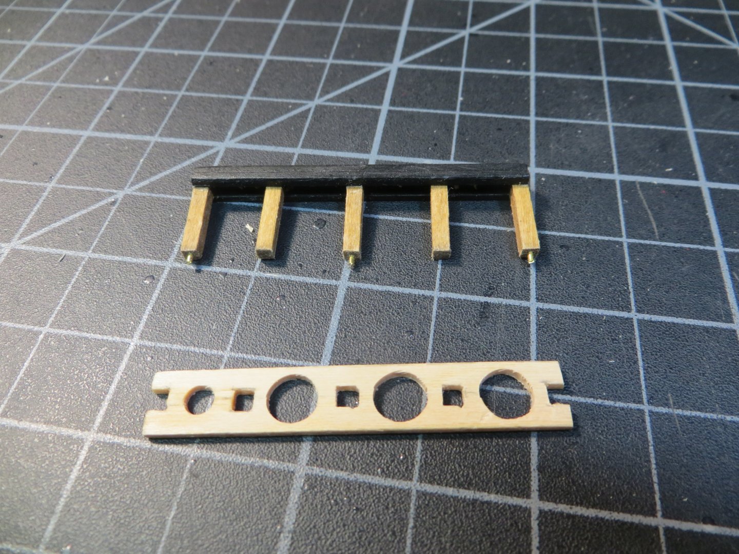
Forecastle Top Rails Builders say that the focsl railing is one of the weakest parts of the ship. I’ve seen the pictures of damaged railings posted on the forum to prove it! To use the kit supplied parts would require making a 1/16” square tenon at the bottom of the stanchion to fit the pre-cut holes in the cover board. I don’t have the power tools required to do this easily. And I don’t want to carve 14 tenons by hand! Also, the laser cut top rail in the kit is only 3/32” wide. I intend to build something sturdy. So, I plan to custom fabricate a 1/16” x 5/32” railing by tracing the cover board on the focsl. This is also 5/32” wide. For added strength I plan to insert a 1/16” brass tube in the bottom of 1/8” square stanchions and a 1/32” brass rod (0.032”) in the top. My original plan was to only insert the rod at the top of the stanchion half way into the top rail from the bottom. But this turned out to be so flimsy I couldn’t even hold it together to do a dry fit. So, I replaced the rods with 5/128” nails. I also extended the hole all the way through the rail so it firmly held the stanchion in place. I pushed the tip into the stanchion and snipped off the head of the nail. But I’m getting ahead of myself! Construction Steps 1. Top Rail a. Tracing paper was used to trace an outline of the cover board. It is very important not to forget to mark the location of the stanchion holes in the cover board! Then transfer this outline to card stock using carbon paper. Cut this out of the card stock. b. Attach the card stock to a piece of 1/16” thick sheetwood. I cut this out along the outline using a jewelers saw. Sand it to shape and round off the top edges. Leave the bottom square. c. Flip the tracing paper over and transfer the locations of the holes to the underside of the rails d. At first, I used the pin vise to make 1/32” wide x 1/32” deep holes in the underside at these marks. Later these were extended completely through the rail and widened to 5/128” 2. Stanchions a. Cut 14 - ½” long x 1/8” square pieces. b. Drill a 1/16” hole in the bottom of each stanchion. I used a pin vise starting with a 3/64” pilot hole c. Drill a 1/32” hole in the top. Slide the drill bit in/out to open the hole to 5/128” d. Insert a 0.032” brass tube in the bottom hole and cut it off on the chop saw to the length required to fit into the square holes on the cover board. These varied so I numbered the stanchions by hole e. Insert the pointed end of the nail into the top hole. Use a test piece of 1/16” thick stripwood and cut the flat end off flush. I filed the cut end after removing it from the test strip. f. Mark and drill the holes for the belaying pins in the railings. The George Campbell plans show 6 holes on each side between the 1st and 3rd stanchions. Drilling holes and inserting brass tube & brass rods in each end of the stanchions (pic before I replaced the rod with cut-off nails) Replacing the smaller rod with cut-off nails. I pushed the nails in pretty far (about ½”?). I did not use any CA on these. Dry fitting the pieces before applying the glue 3. Assembly a. Lay the rails top down. I used Weldbond glue to attach the top end of the stanchions into holes in the rails. Do a half at a time to reduce setting time for the glue. b. Apply the white glue to the bottom of each stanchion and dab of thick CA into each hole on the cover board to help hold the brass tube in the focsl wood. Rail face down with white glue already applied to the under-rail side and glue dabbed onto the bottom before attaching to the holes in the deck cover boards c. Press the assembled rail into position on the cover board. Do all the gluing at one time so there is still a little wiggle remaining to adjust everything. d. Last but not least, I applied a little Weldbond to hold the two halves together at the bow. The orange spring clamp you see laying on the desk was used to hold it while the glue dried Assembled rails before painting 4. Finishing a. Once the glue had dried overnight, I painted everything with two coats of black acrylic paint. I refrained from painting beforehand to get maximum adhesion with the glue. b. I plan to install the belaying pins now. I will blacken them, same as the brass cannons. I will do that after the breast rail is completed on the focsl. This also has quite a few belaying pins and both can be done at the same time. Focsl Top Rail after painting The next step is to make the Breast Rail that sits at the aft edge of the focsl deck. This will be made the same way as the rail on the quarterdeck. Thanks for looking in, Ed


-
Hey Fellow Rattlesnake Builders, I'm preparing to make the Focsl Breast Rail, as it is called in the instruction manual. In researching how others have built the rack of buckets, I'm finding that some builders have placed the buckets on the quarter deck railing. But the instruction manual states that the buckets are on the focsl breast rail. I am also finding that there is not enough space between the stanchions if you make it with 7 stanchions. Builders cut it down to 5 in order to get the buckets to fit in between. That seems like a good solution to that problem. Since I've already completed the quarterdeck rail, I am going to go with the focsl rail for the rack of buckets. Unless someone has a compelling reason to avoid doing this? I'm just curious. Thanks, Ed
-
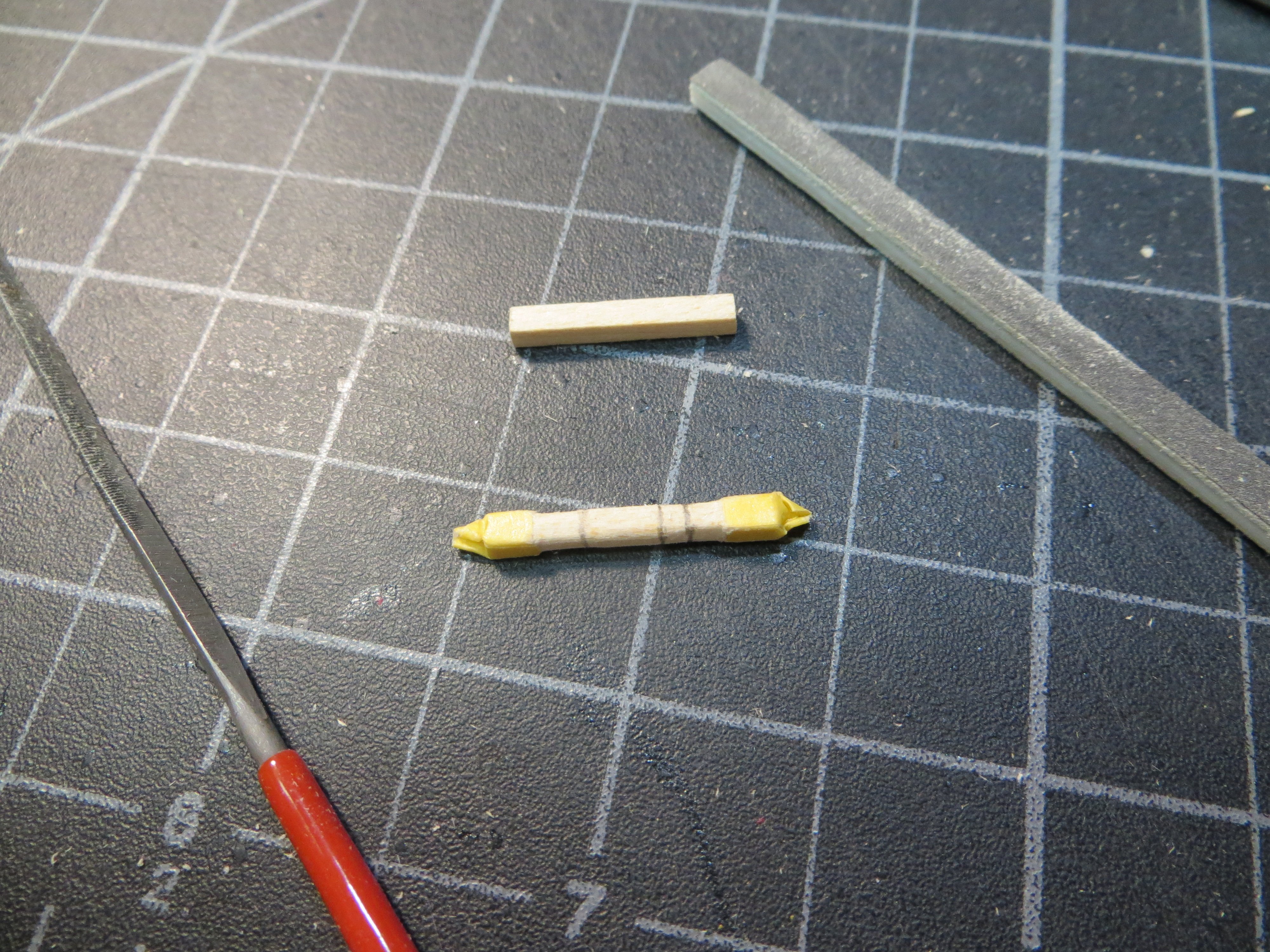
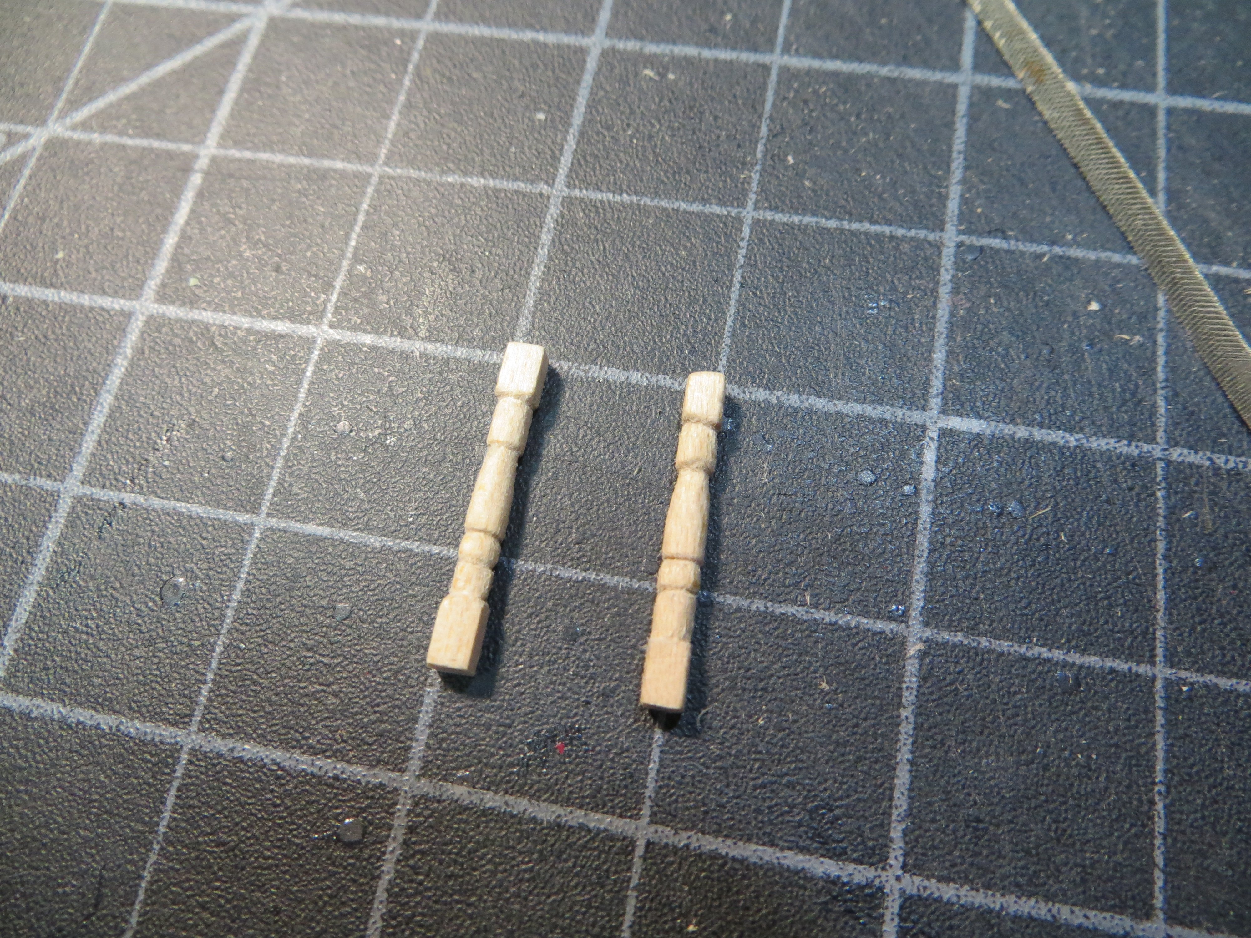
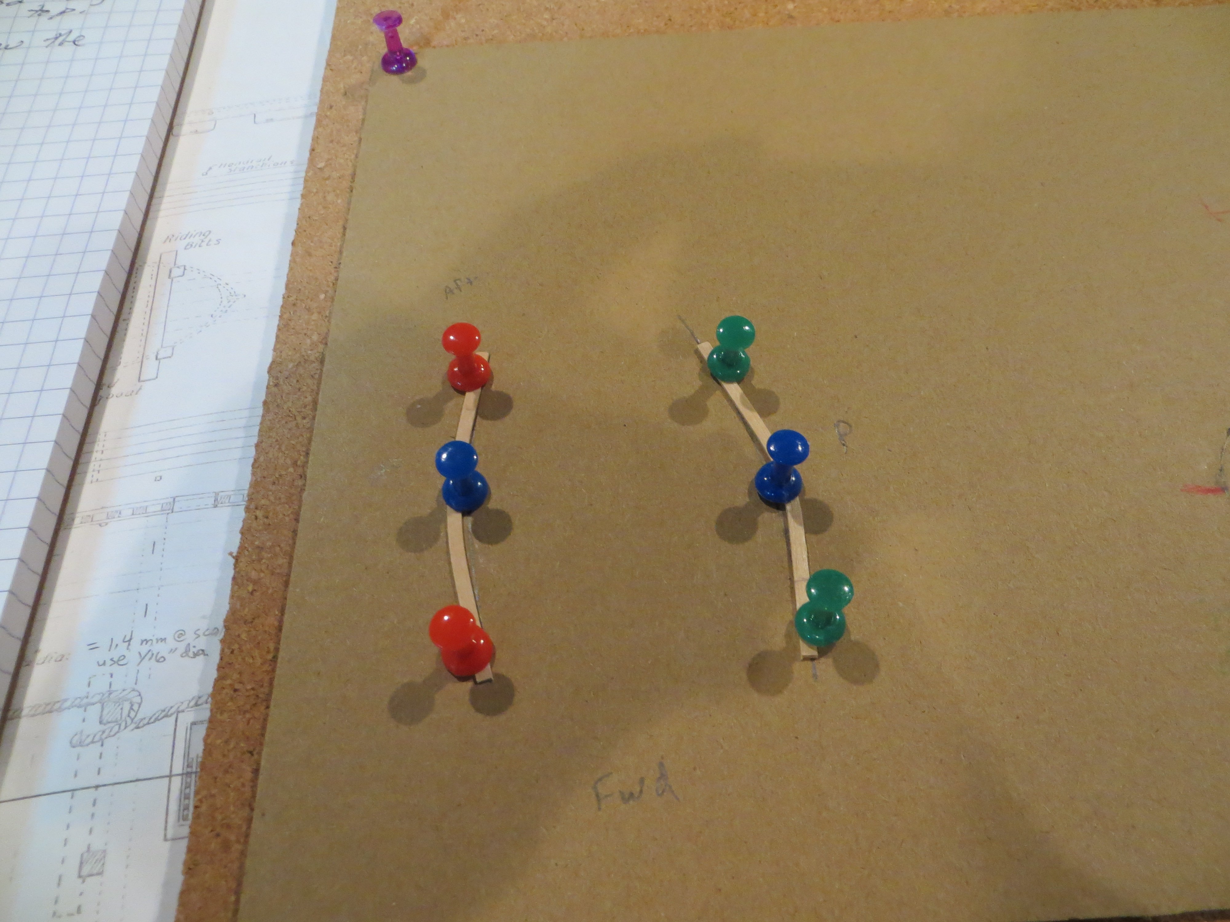
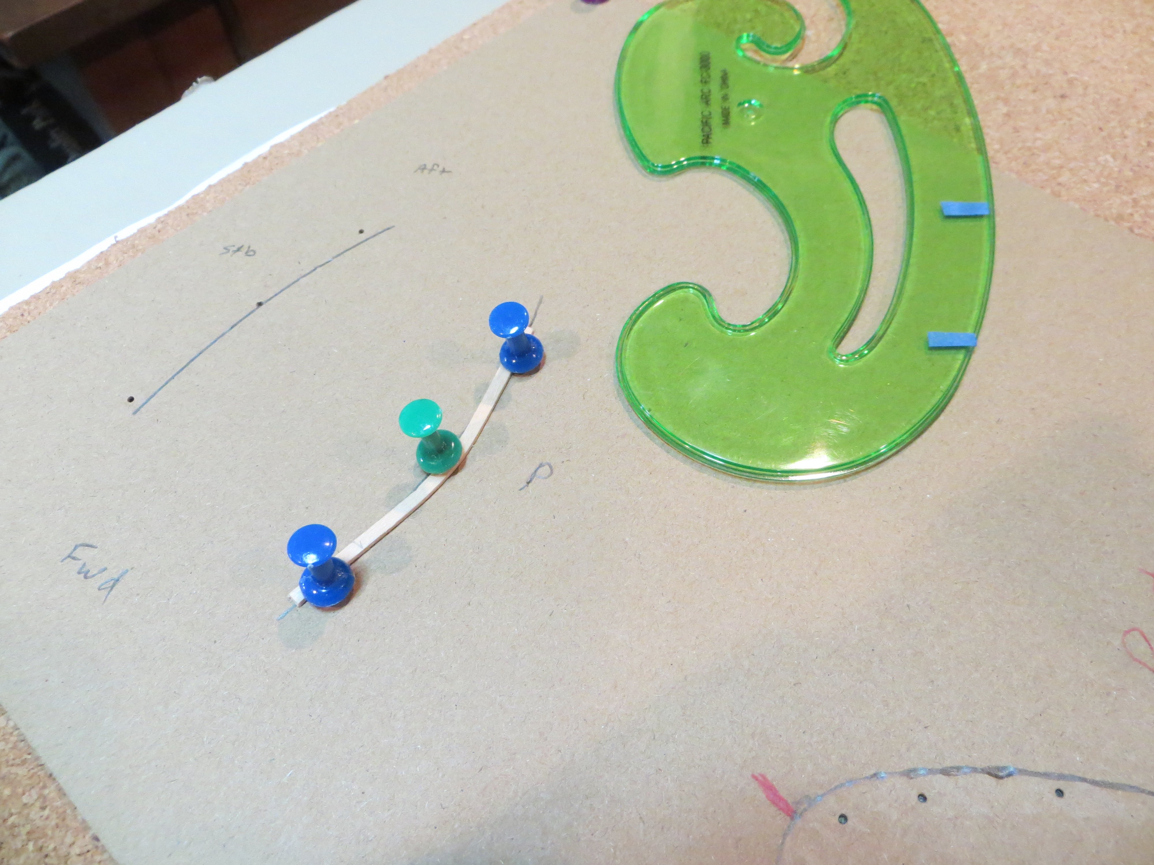
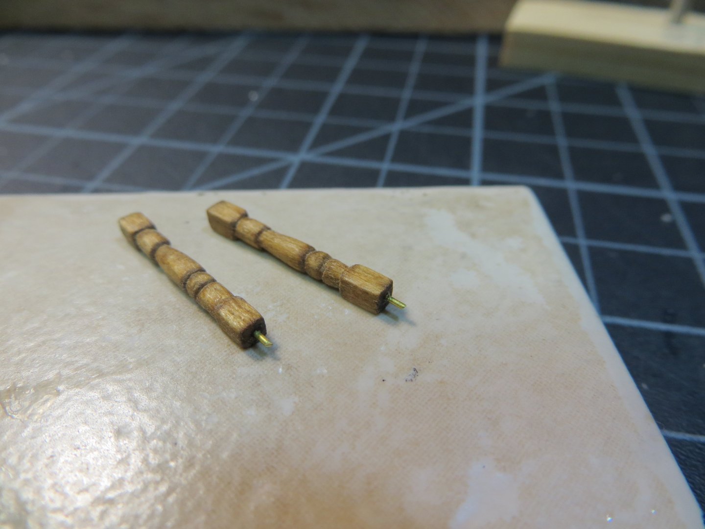
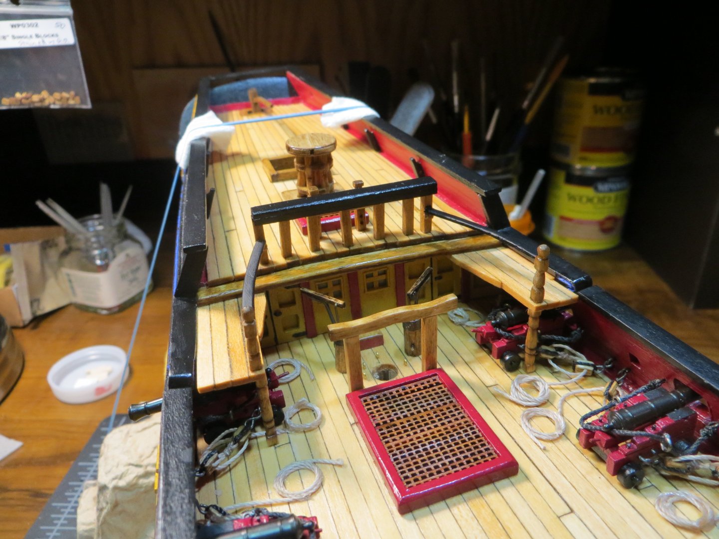
Fixed Gangway / Stanchions & Balusters / Quarterdeck Fore-Rail Like most builders, I decided I was not going to build the portable gangways that connect the focsl deck with the quarterdeck. The main reason is that they end up covering the cannons. The cannons are one of the highlights of the Rattlesnake, IMHO. Secondly, they were built to be removable and stored. So, I decided to remove them and store them below deck! The fixed gangway was not removable. It is an extension off of the quarterdeck. One on each side. A handrail connects the railing at the forward end of the quarterdeck with the baluster at the front corner of the gangway. The plans show that the upper and lower balusters on the gangway had a decorative design to them. So, all these pieces need to be built together. I started with the gangway. Fixed Gangway I made the gangway from the same 1/16” x 1/8” stripwood as the other decks. According to the plans 4 planks will cover the required width. The inboard plank has a curved shape to it. I used lead pencil to blacken one side of the plank to simulate caulking, same as the rest of the planking. I edge glued these pieces together. The planks were stained with Minwax Natural to match the decks. The tricky part was how and where to attach the gangway. I decided to glue it under the cross beam at the forward edge of the quarterdeck. Shockingly the port and starboard sides are not exactly the same. Some fitting was needed on the port side. Four pieces of planking are cut and ready to assemble Edge gluing the planks with lead pencil between Staining. I taped off the edge that would be under the beam so I could get good adhesion with wood glue Lower Support Balusters for the Gangway I temporarily clamped each gangway in position to get a measurement for the support post. I made both the upper and lower balusters from 3/32” square stock. I found that the build log of Jon Gerson was helpful for carving the posts. A combination of a triangle shaped mini-file and a sanding twig were used to make the decorative design. Ends that needed to stay square were taped off. Pencil marks are made to indicate the areas to remove wood The two posts after carving and sanding After staining with Minwax Golden Oak, support pins were inserted in the bottom Here is a pic of the gangways and lower balusters after being glued in place Quarterdeck Fore-Rail This short rail sits all the way forward on the quarterdeck. I started out by cutting 7 stanchions from 3/32” square stock. Builders seem to make this rail (and the similar focsl aft-rail) in different ways. I decided I liked the way David Lester built his rail the best. It seemed sturdy enough to hold rigging and also looks good. He made a channel that the stanchions fit in snuggly. This provides 3 sides for gluing. I used 3/16” x 1/16” for the top and 3/32” square stripwood for the sides. A 3/32” square piece was used to make sure the space in the channel was the correct size. The 3/32” side pieces overlapped the top slightly. These were sanded flush with the 3/16” top piece after gluing. I also sanded the bottom down to reduce the height of the rail. While I was cutting the stanchions I made 7 extras for the Focsl rail. All the stanchions are cut to a ½”. Pic showing the cut stanchions. They were stained with Minwax Golden Oak. Three of the stanchions were fitted with a brass pin to secure them when glued. Only the ends and center one got pins. The other four were simply glued in between these 3. Here is the completed channel for the railing. The tricky part was trimming the stanchions to match the camber of the deck and still keep the rail level! Lots of sanding and test fitting was needed! And of course, getting the holes for the 3 pins to align is always fun. Upper Balusters for Handrails The next step was to carve the upper blusters for the handrails. These were done similar to the lower ones; except I made a rounded knob at the top. Brass pins were inserted into the bottom to secure them Pic of the completed rail on the quarterdeck and the balusters for the handrails Handrails for the Fixed Gangways I made these from 1/32” x 3/32” stripwood. I used a French curve to find the right bend for the handrails. Then the wood was soaked in water. I used the French curve to make a pencil mark on cardboard stock laid over corkboard. I cut the wood longer then needed. The stripwood positioned over the pencil marks and held down overnight with push pins. The next day they were custom fit into the space between the q-deck rail and the balusters. I rounded off the edges and painted them black. I glued a couple of tiny pieces of wood to the q-deck stanchions to provide more gluing surface for the handrails. These handrails are really delicate. I hope I don’t break them later in the build! They were a pain to make! I marked the spot with tape on the French curve to match what’s needed on the ship. This curve was marked on cardboard stock that is pinned to a corkboard Extra long handrails pinned and drying to form a curve Before I attached the handrails I added a few things on the deck. I glued down 4 eyebolts that need to go on the deck around the main mast, the bilge pumps and the large bitts. I don’t want to break the handrails sticking my fingers down there afterward! Then the handrails were glued in place. Here are some pics of the end result. The next step is to make the center rail on the Focsl Deck. Let me know what you think of my work. I always appreciate your feedback & comments. Thanks for looking in, Ed


-
Hello Redcoat! Looks like you got a little happy with the trigger finger!! All I can tell you is that the instruction manual that comes with the kit says Copyright 1994. The intro states that George F. Campbell prepared the blueprint plans for Model Shipways in 1963 as a solid hull model. Then Ben Lankford converted the plans to a plank-on-bulkhead type hull with the current instruction manual in 1994. So, either 1963 or 1994 depending on which model type you are talking about. Hope that is what you wanted to know.
-
Just goes to show that great minds think alike!! Thanks for your comments.
-
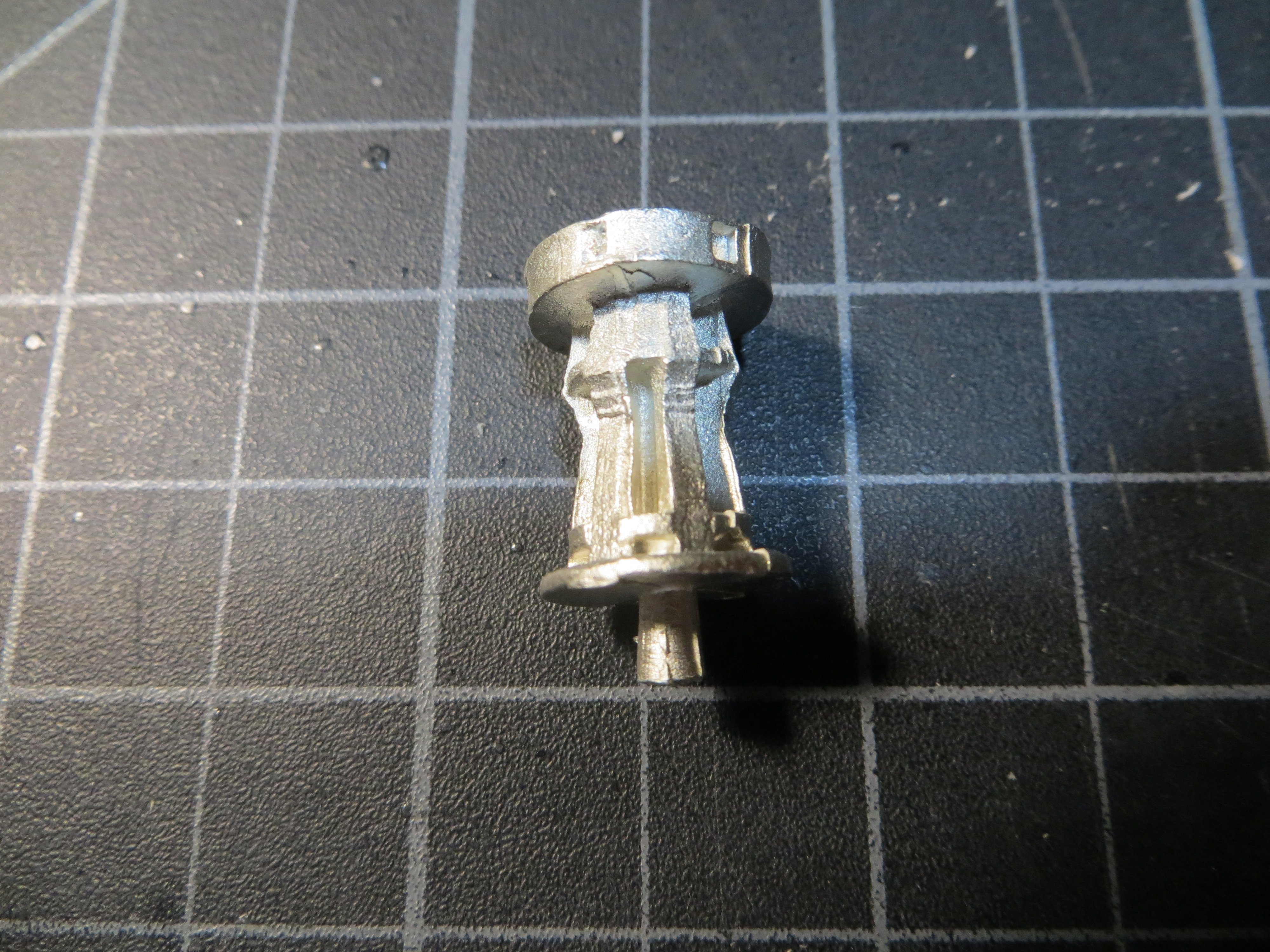
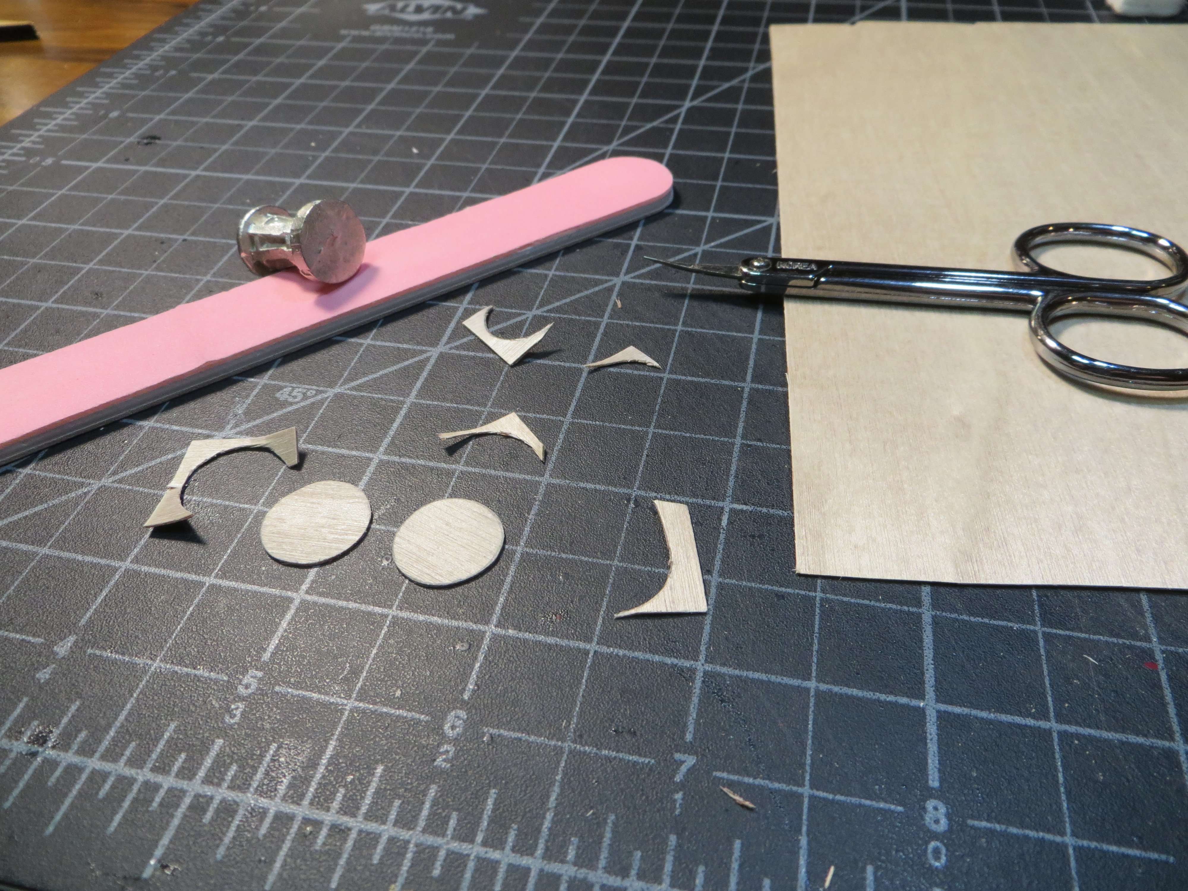
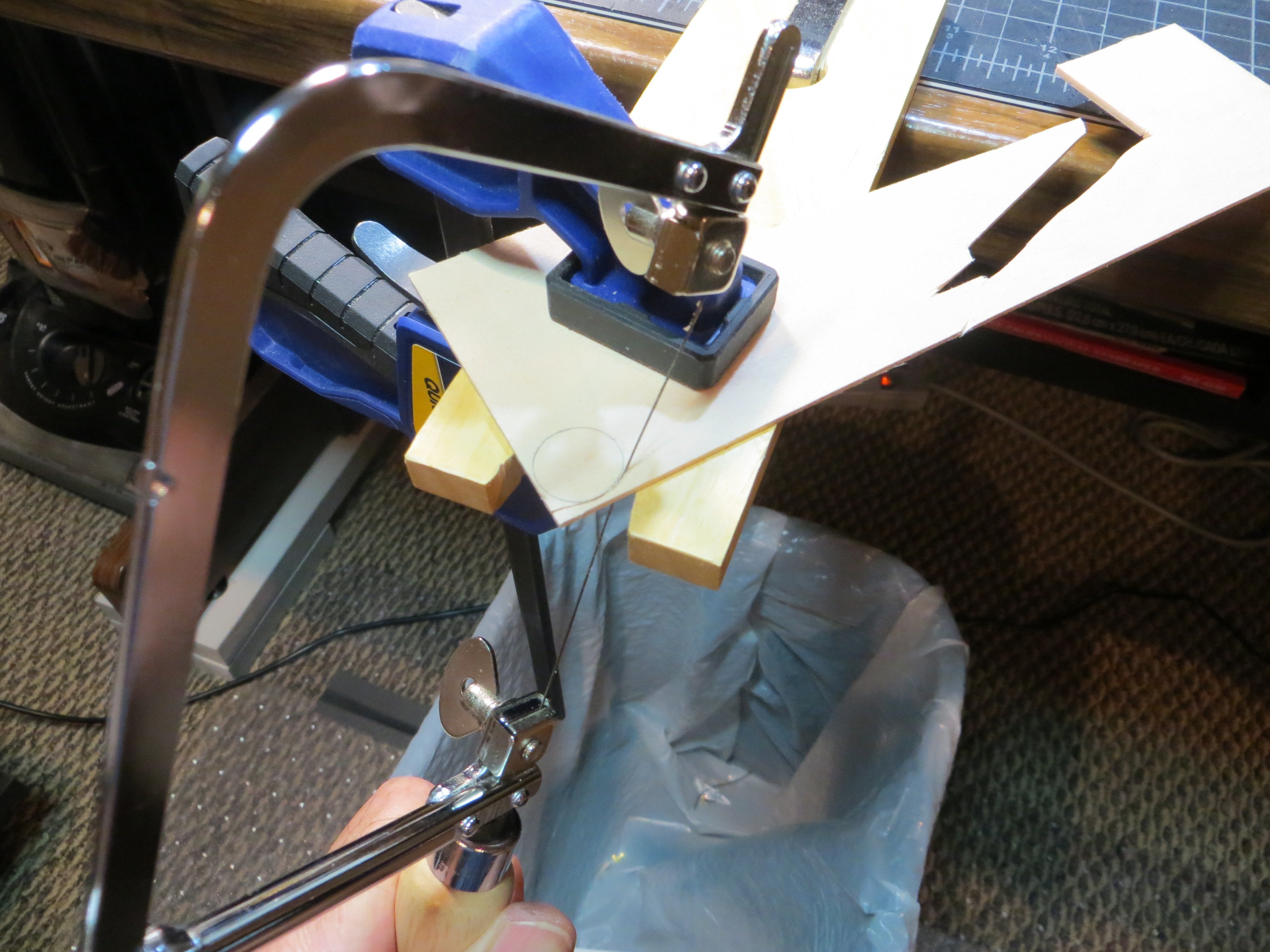
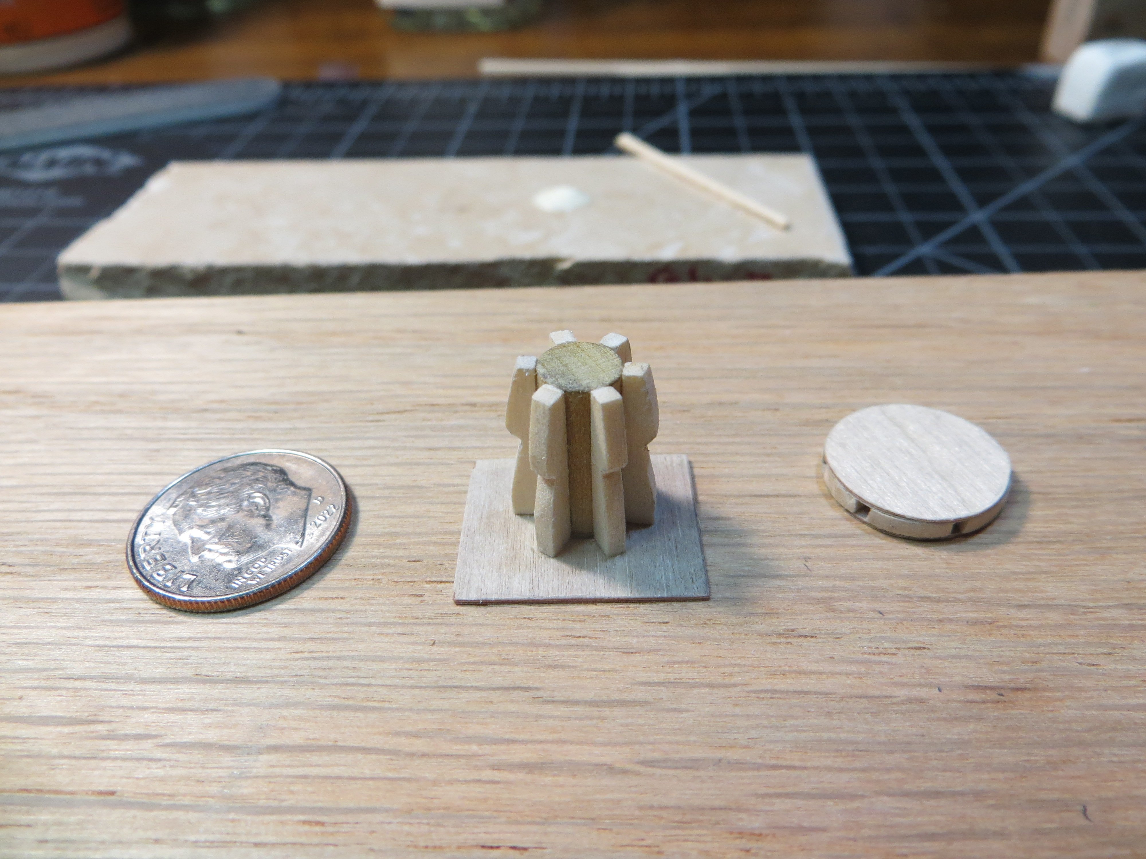
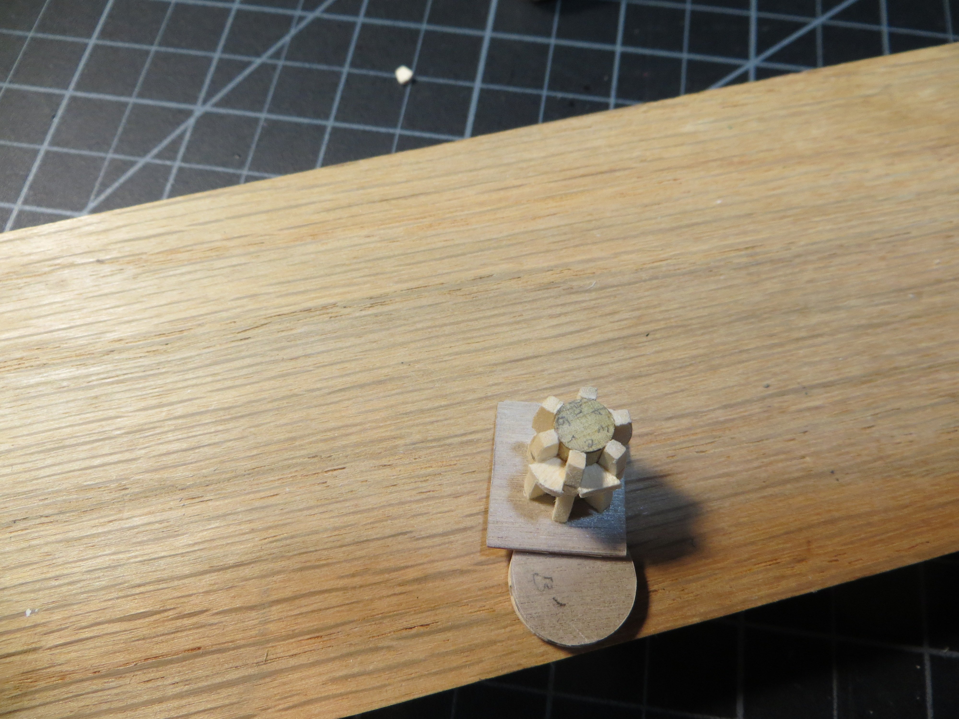
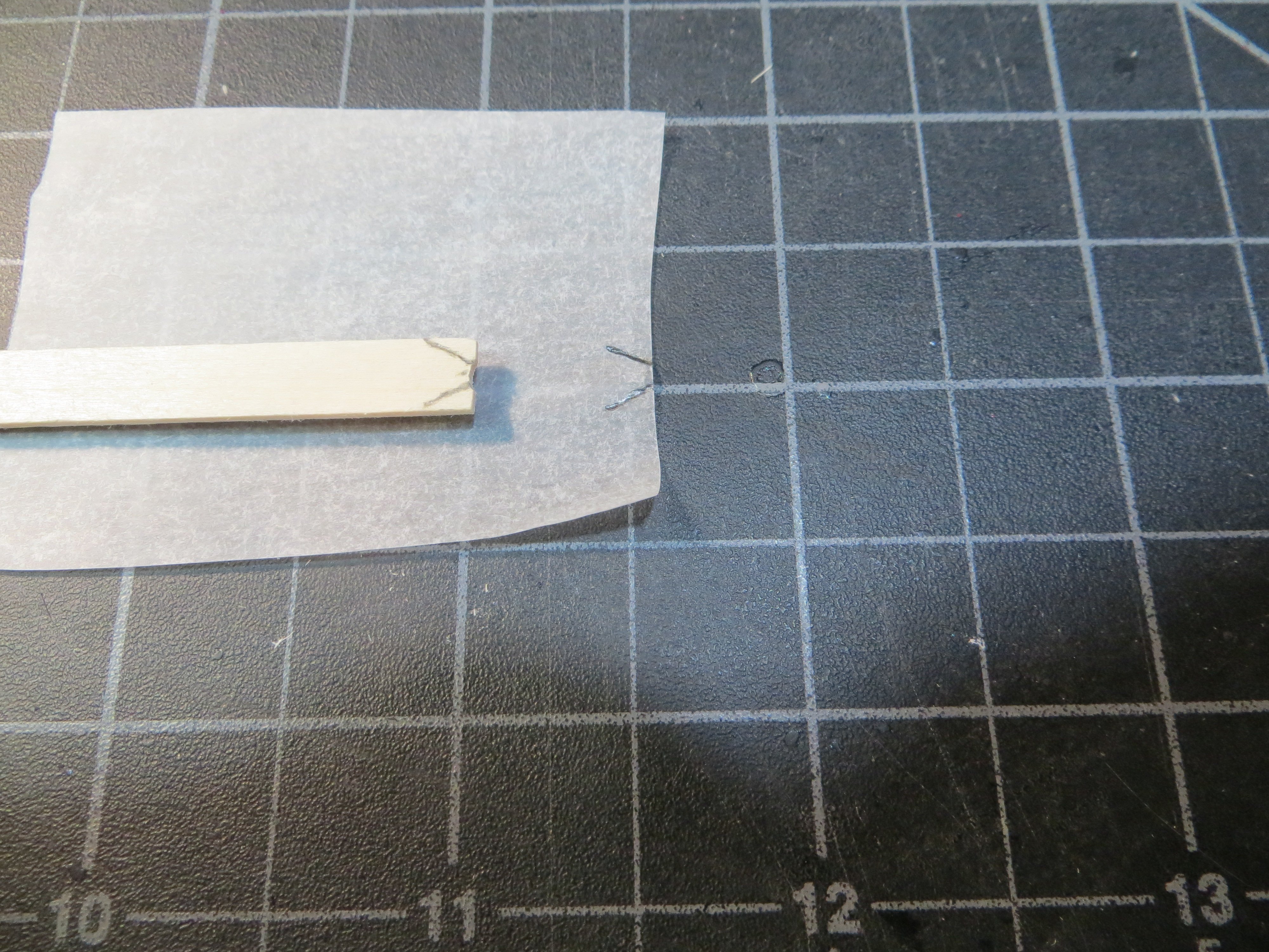
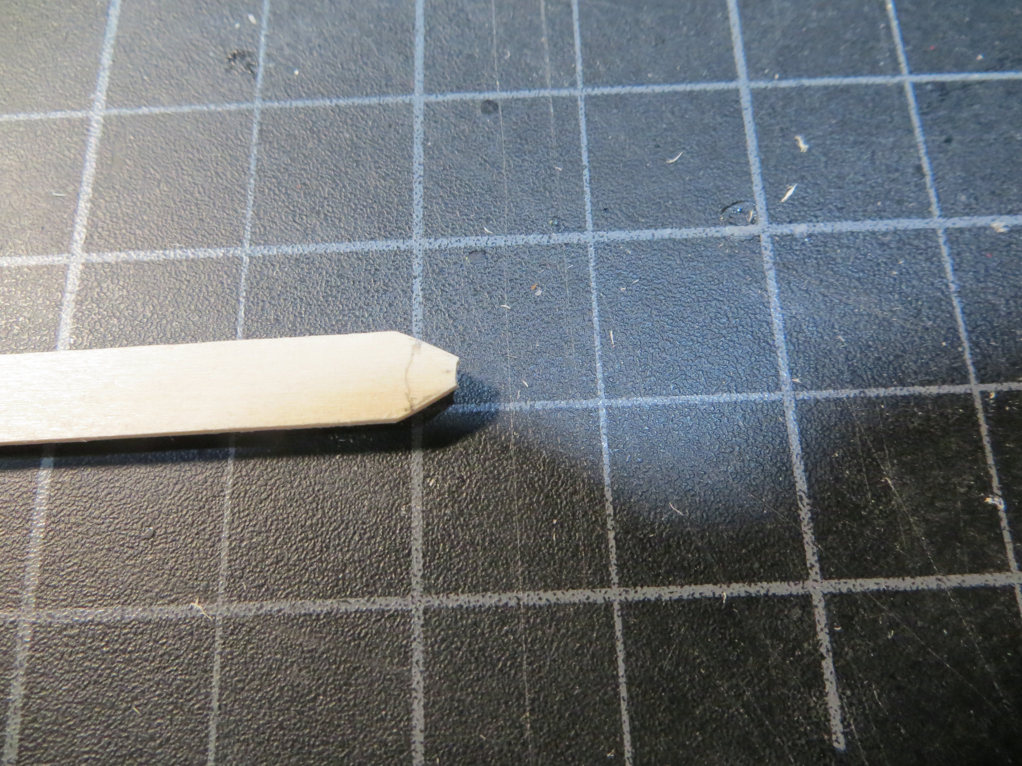
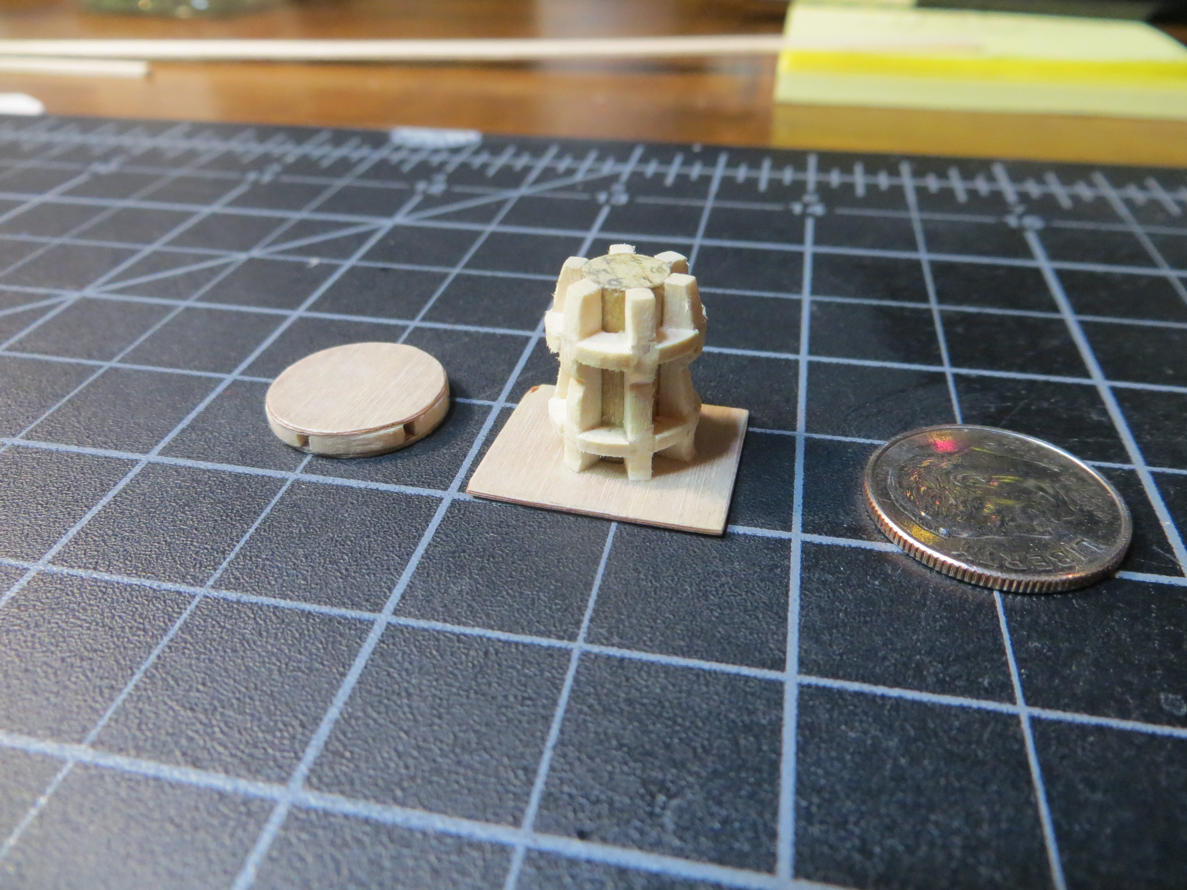
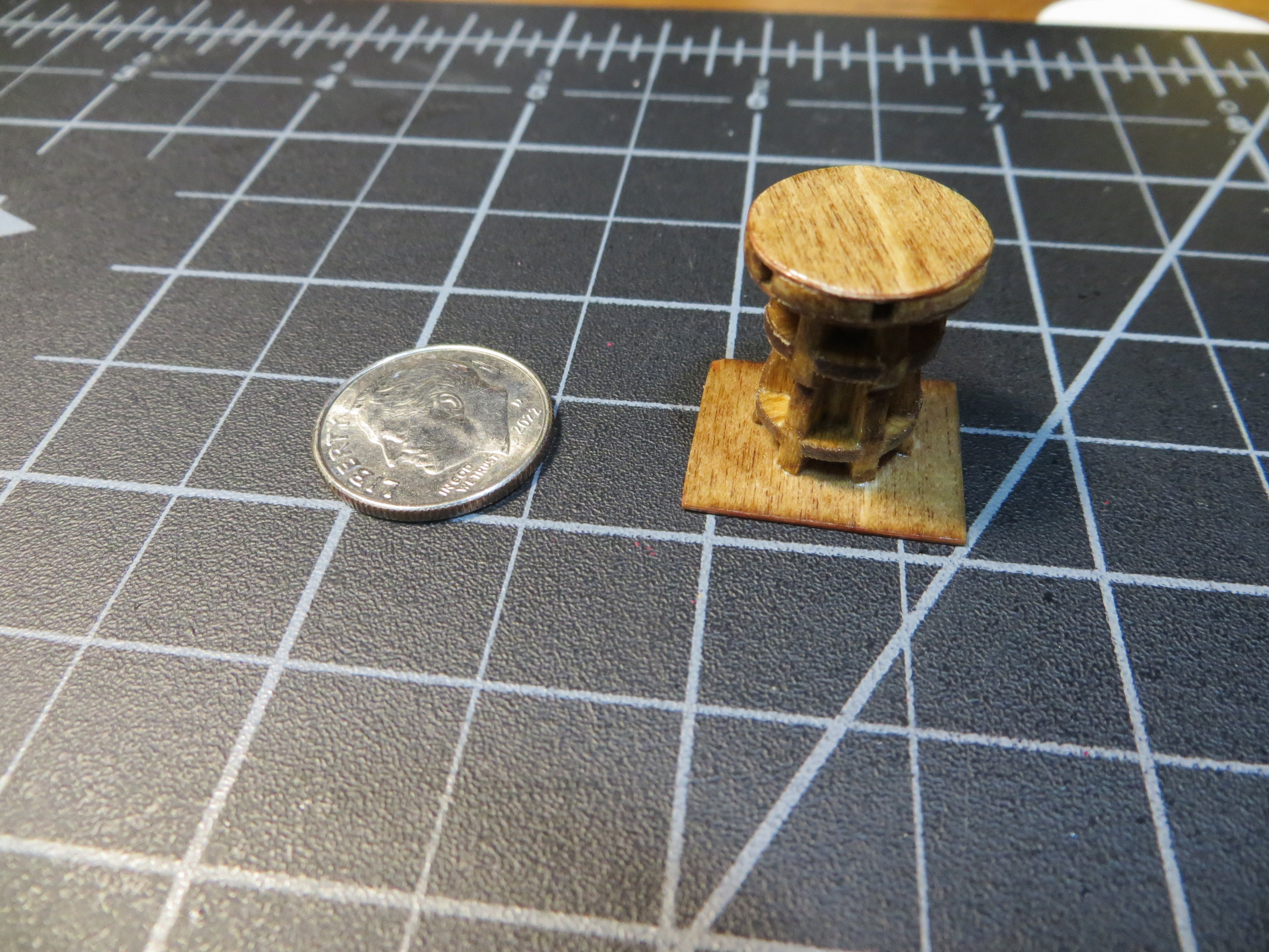
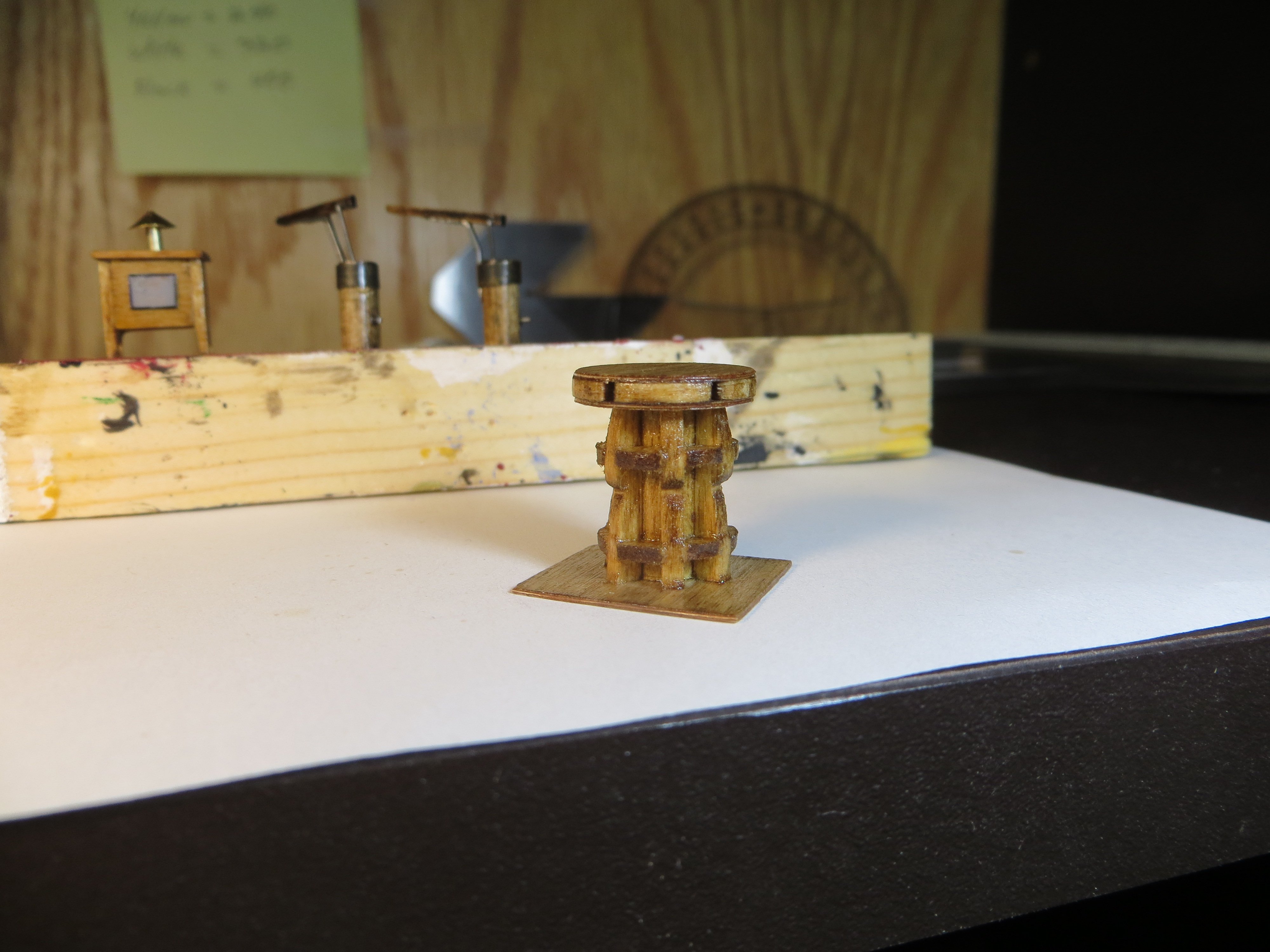
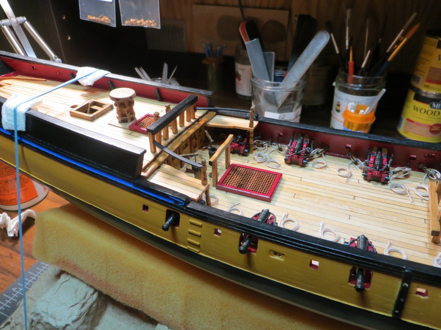
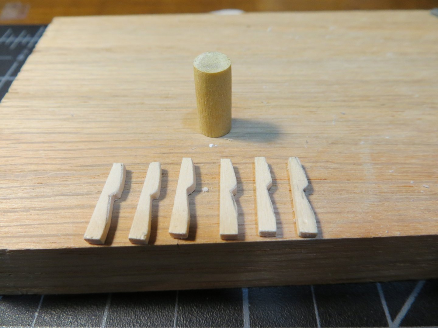
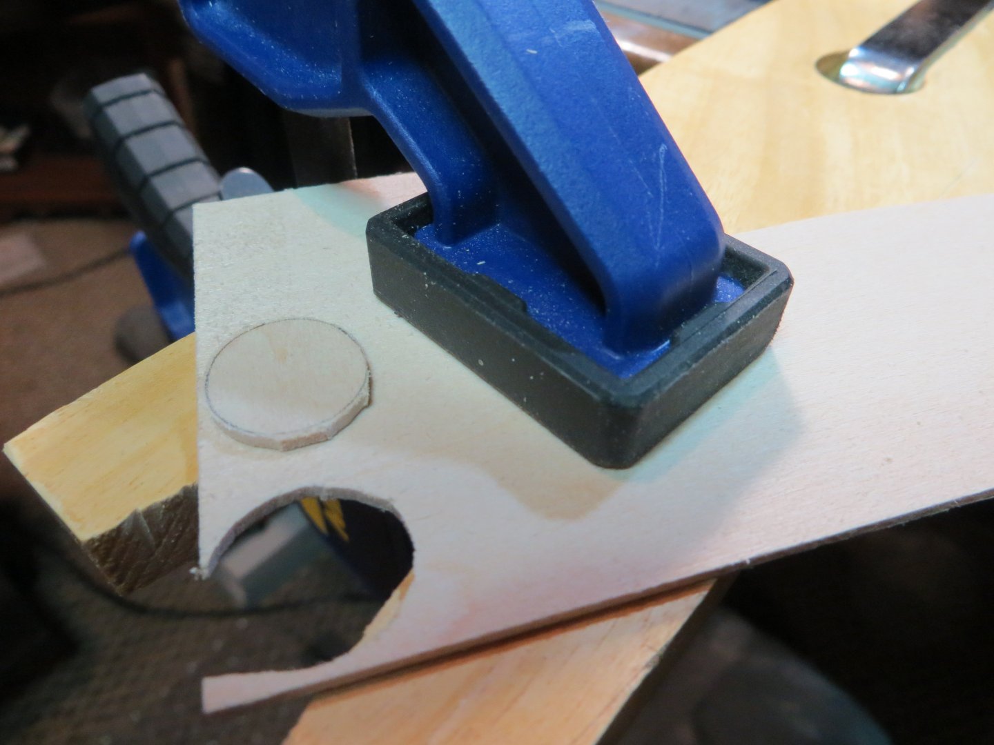
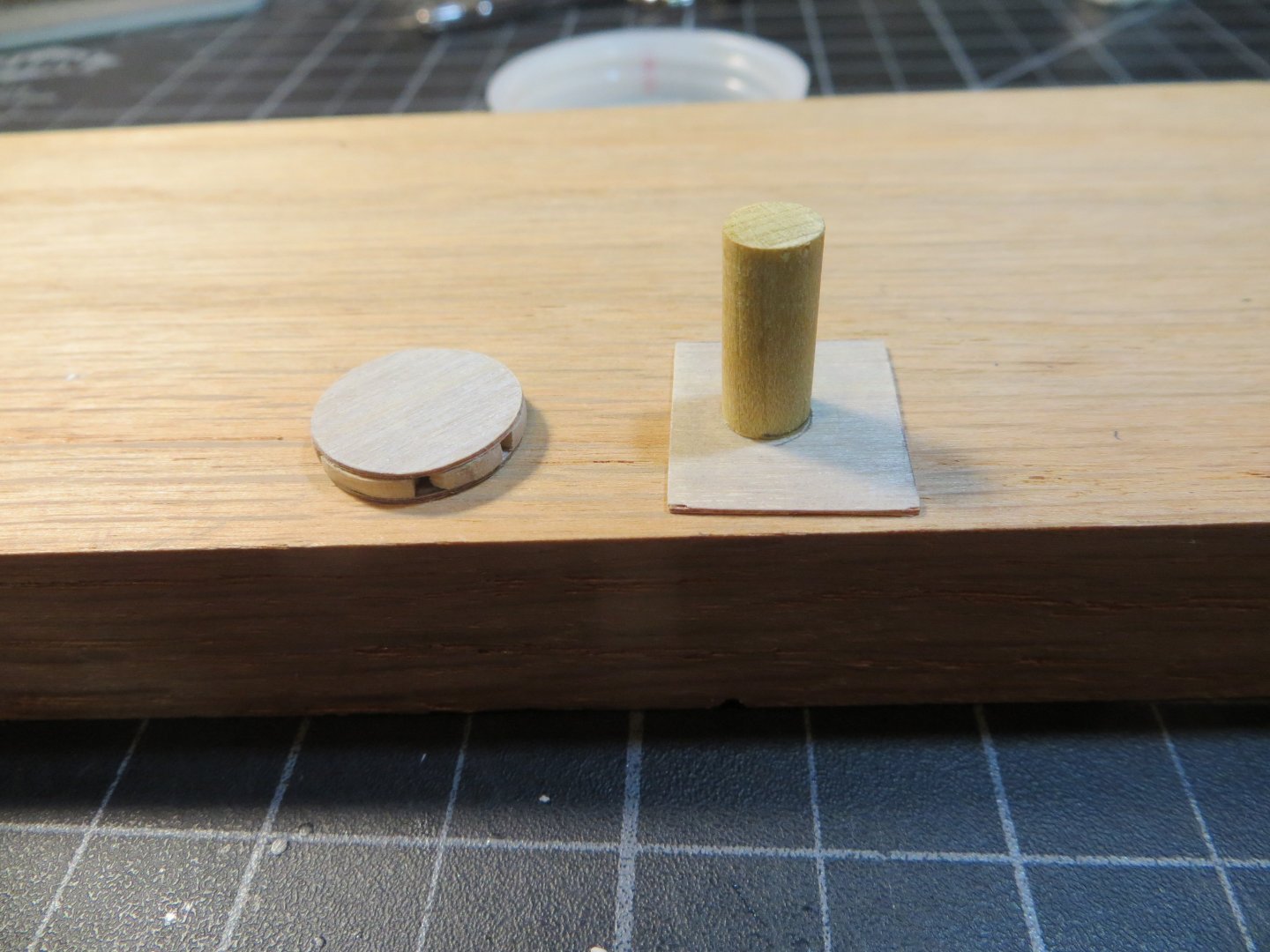
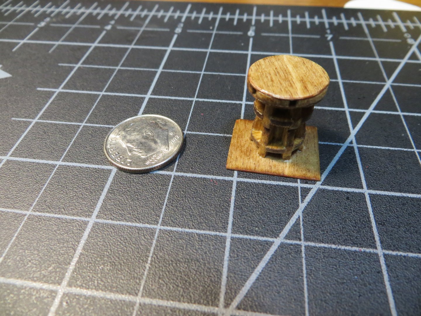
The Capstan As mentioned, I decided to scratch build the Capstan. This looks like a challenging task and I hope I’m ready for it. On the actual ship there was a double capstan. The lower half was in the officers’ quarters on the gundeck and the upper half was on the quarter deck. Since only the upper half is visible on my model, that’s all I plan to build. Pic of the Britannia metal capstan supplied with the kit. It was useful for taking measurements from. Center Spindle -- I used a ¼” dowel that was cut to a length of 9/16” as determined by the blueprint plans. Some instructions say to make it into either a hexagon or an octagon. I decided to just leave it round. Top Disk – Is a 3-piece sandwich. The top and bottom were made from birchwood sheet. I used the top of the Britannia part to trace the size. I was able to cut these out with curved scissors. In the center is a thicker notched disk that the bars for turning the capstan are inserted. I used a 1/16” piece of sheetwood that was cut in a circle with a jewelers saw and then sanded to shape. Six - 9/64” deep notches were cut around the circumference using a mini-file. Steps to making the top disk parts Capstan Bed or Base – The blueprint shows this as a rectangle. The instruction manual shows it as a circle. I made a rectangle according to the size shown on the blueprint. The capstan is supposed to be off center. I used a piece of birchwood sheet cut to this size. I glued the dowel to the base before moving on. Here is the dowel glued to the base and next to it is the top disk all glued together Whelps (6 ea.) – A lot of hand sanding was needed to shape the whelps. I used 1/16” x 1/8” deck planking stripwood. The height needs to be equal to the center spindle or 9/16” tall. The Britannia metal part was used to make a sketch of the outside edge of the whelp. After making the first one, I used it to sketch pencil marks on the others for shaping them. The 6 whelps were glued to the center spindle and the base. Whelps are prepared and ready for gluing to the center spindle Whelps glued to the center spindle Wedges – Two sets of 6 wedges each are required to fit between the whelps. These are so tiny; they are hard to make. Because my whelps are not perfectly fitted evenly around the spindle, each wedge had to be custom made to fit. After the first one was made, I drew the size on some tracing paper to make the others. They were slowly sanded until they fit the space between each whelp. Then I cut them off the piece of stripwood. After the glue dried, I sanded them down so they were flush in a circle. I completed the top set first, then the lower set followed. Initial shape traced onto the stripwood Sanded to fit between the whelps. Note the notch in the front to fit against the dowel Completed wedge cut away from the stripwood First two wedges glued in place Completed capstan after initial sanding Capstan after 3 coats of Minwax Golden Oak All four of the new pieces were given a coat of Minwax satin finish polyurethane I will provide more pics when these pieces are attached to the decks. I’m not sure what I’m going to work on next. Options include the fixed gangways with railings, focsl railings, head rails at the bow or the catheads & anchors. Does anyone have any recommendations? Are there any reasons to do any of these before the others? Thanks, Ed


-
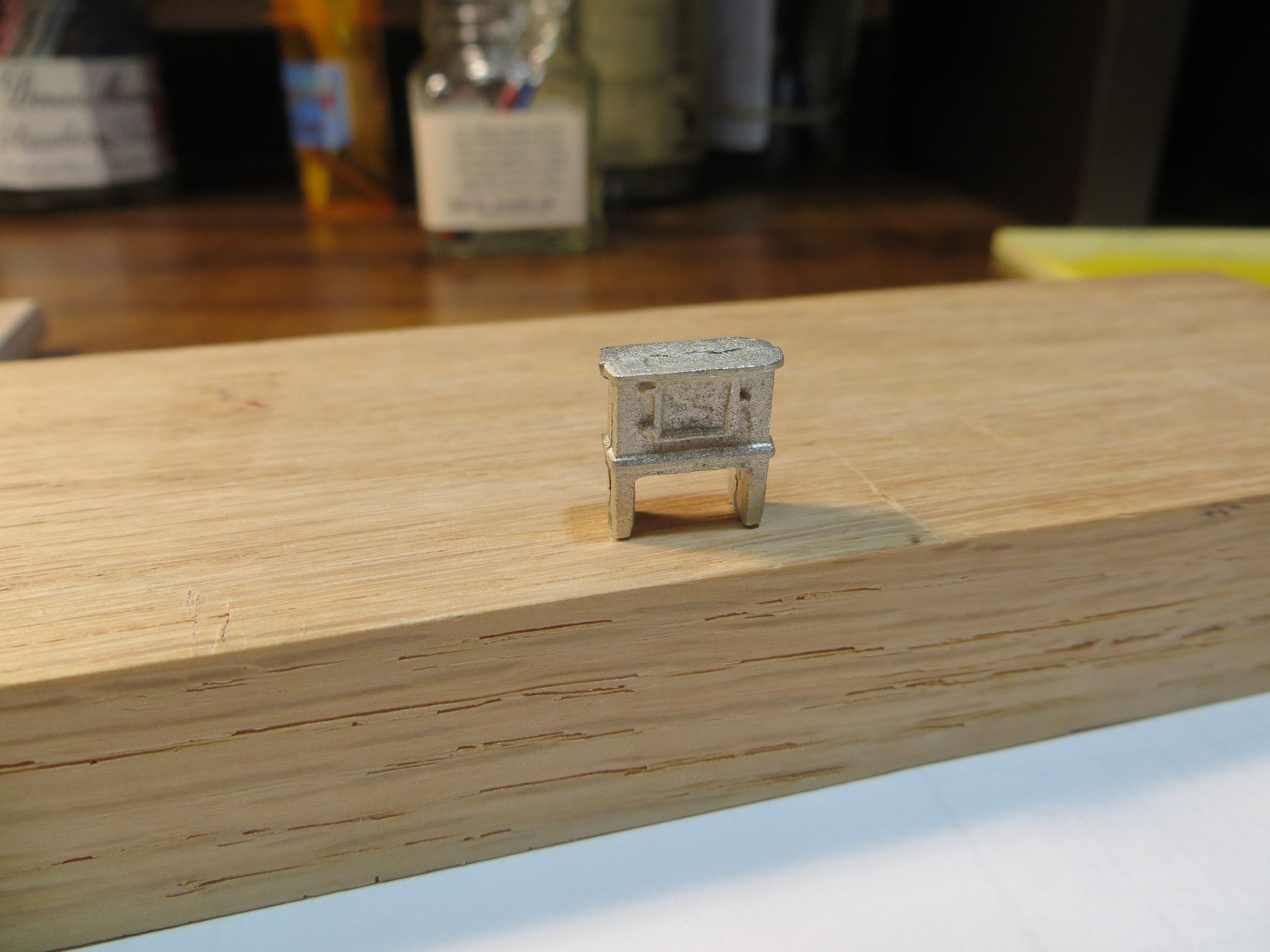
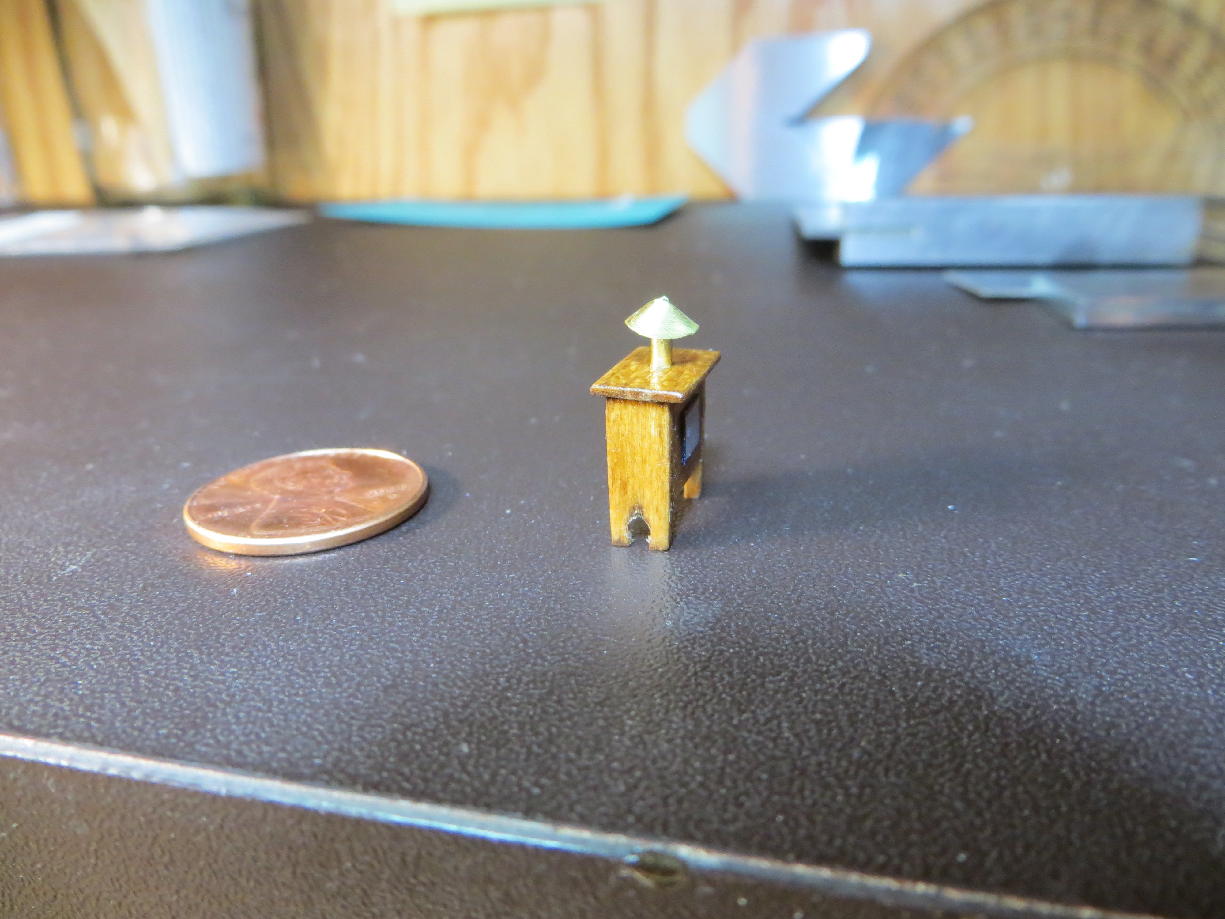
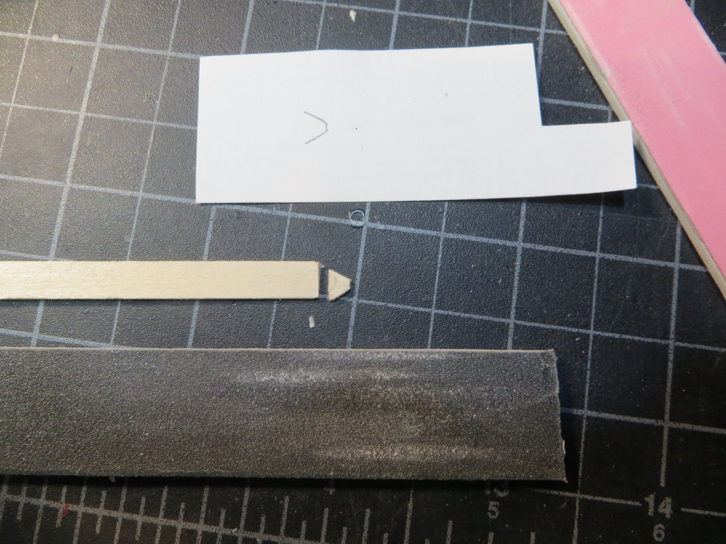
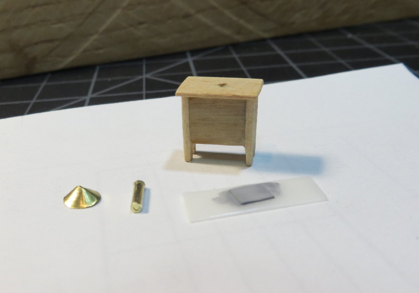
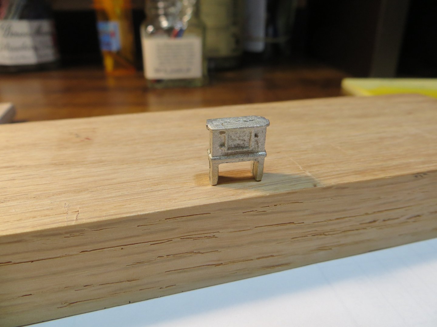
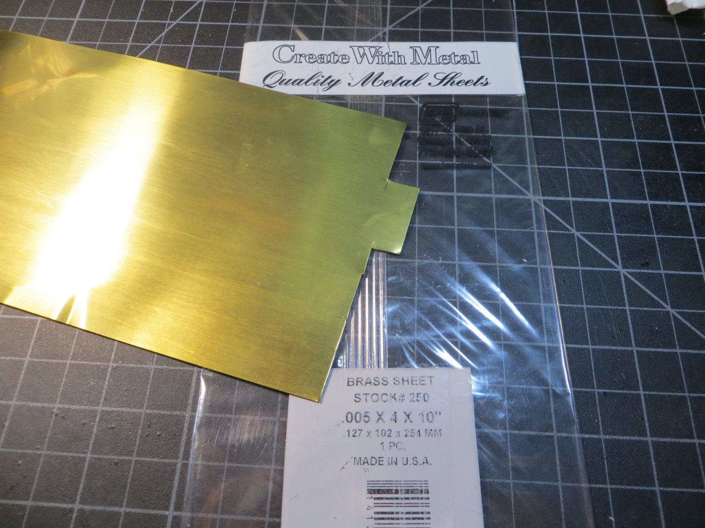
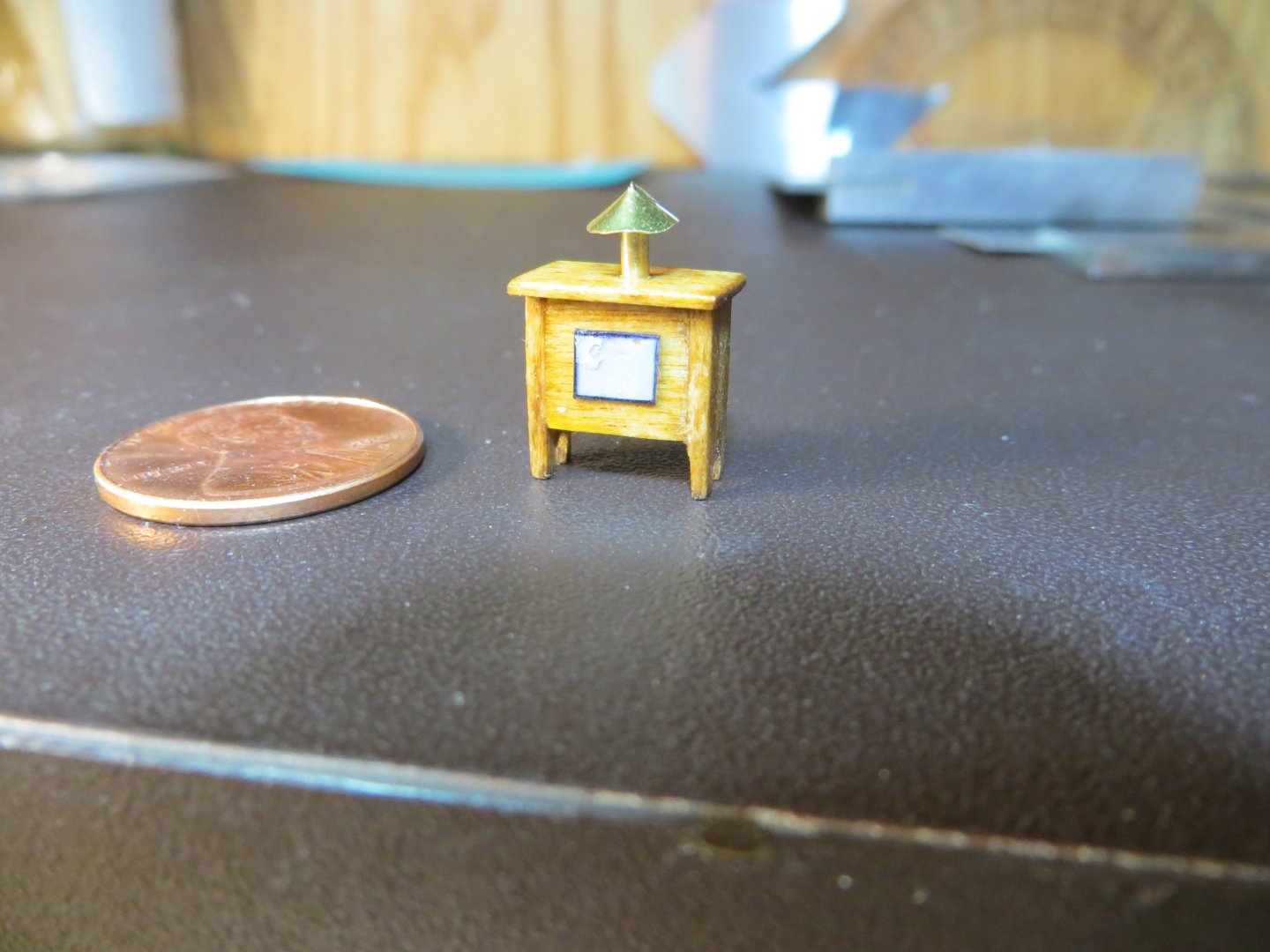
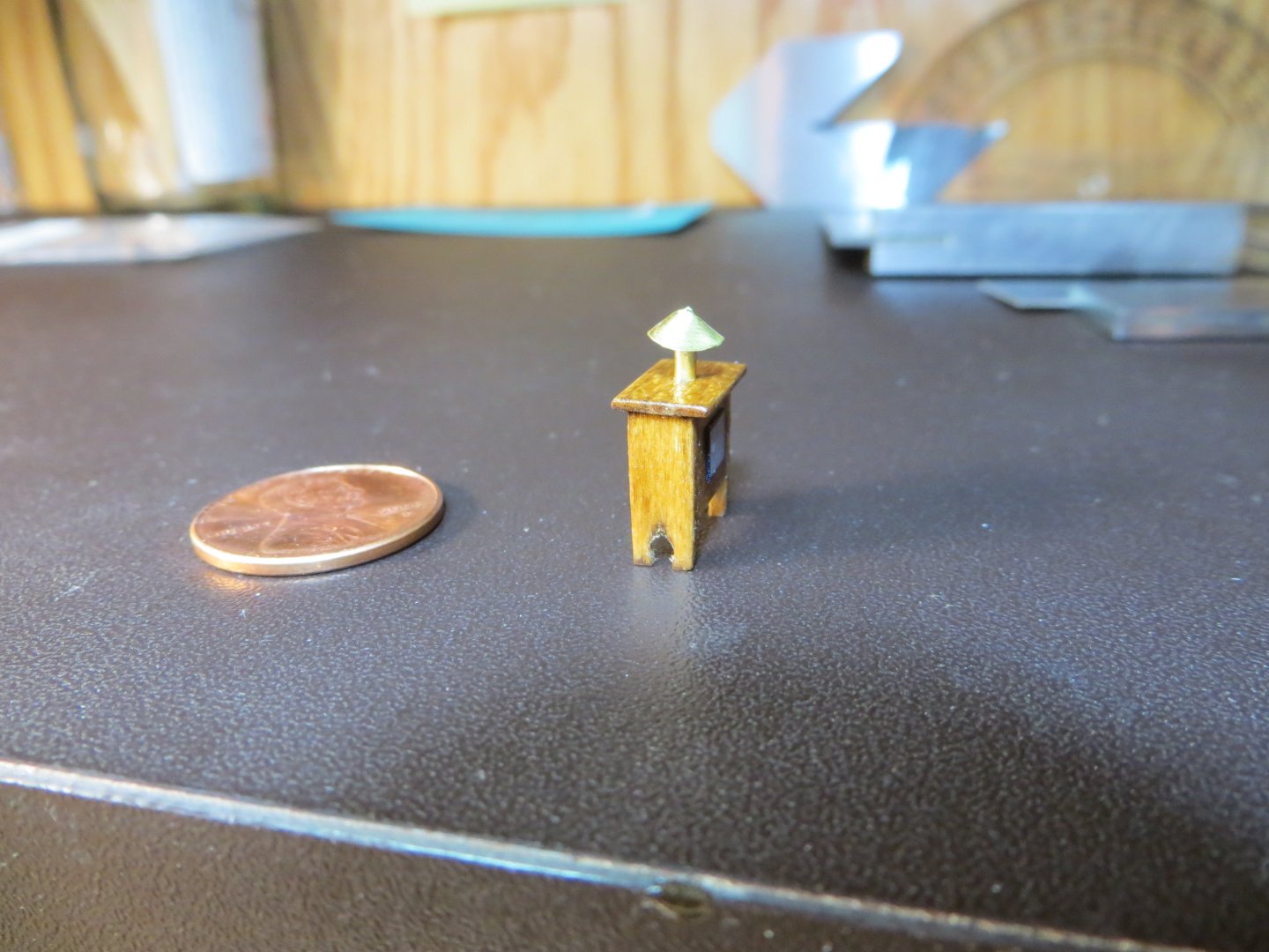
The Binnacle The Binnacle is a box that I think looks like a vintage counsel television set! It contains the compass for navigation, so it stands forward of the tiller. Candles were used to light it up through the night. The chimney on the top is to let the heat escape from the box. Here is the Britannia piece supplied in the kit. I made the binnacle from scratch. The main box is 3/16” deep. A suitable size piece of stripwood is not provided, so I cut off a piece of scrap left over from the bulkheads. These are 3/16” plywood. I cut this to size. This provides a solid core. I cut stripwood for the sides that was long enough to form the legs. Another piece was cut for the top. I made it overlap the box on all 4 sides. These pieces were glued together. Wood was cut out to make it look like there are 4 separate legs with a curved hole in the middle. Next, a piece of plastic packaging was cut out to simulate the “door/window” in the front. Ben Langford said in the plans that the chimney could be omitted, but I thought that would be a cool looking detail. I used the below sheet of brass that I had left over from my last model to make a cone to cover the top. (I also used this for the bands on the elm pumps). This was a bit of a challenge. It was very difficult to bend such a small piece of metal into a cone shape! It took three tries to get it right. I used a scrap piece of brass rod for the chimney. I decided to leave the brass look to let it stand out a bit more. This is the brass sheet. And also, the pieces ready for final assembly A couple of coats of Golden Oak were applied and the pieces assembled Again, I’m going to wait until a little later before gluing this to the deck. I’m afraid I might knock it loose a few times before the deck is a safe enough place! I’m working on the Capstan now. Just got started, so might be a little while before I have something to share. Thanks for looking in, Ed
-
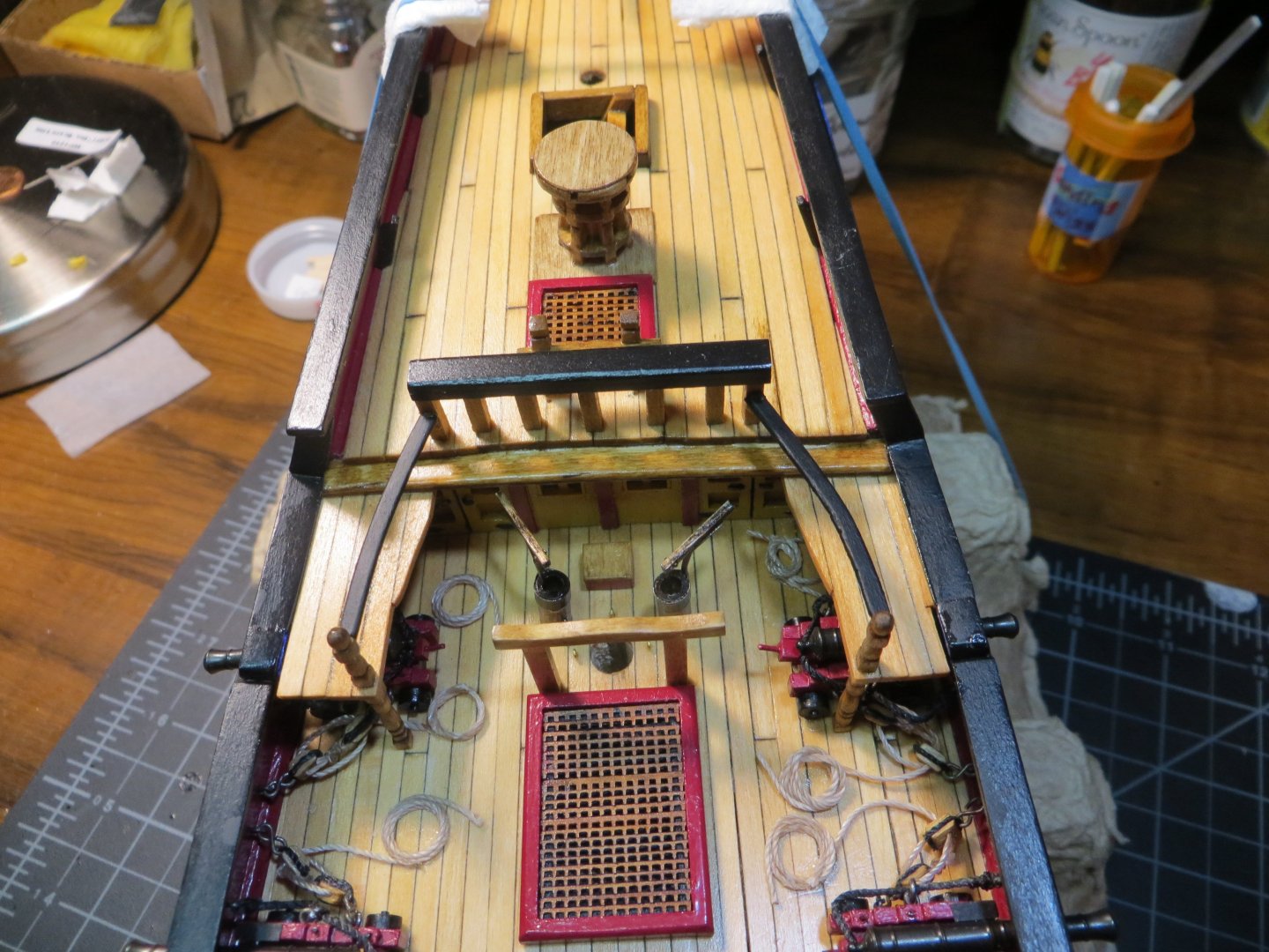
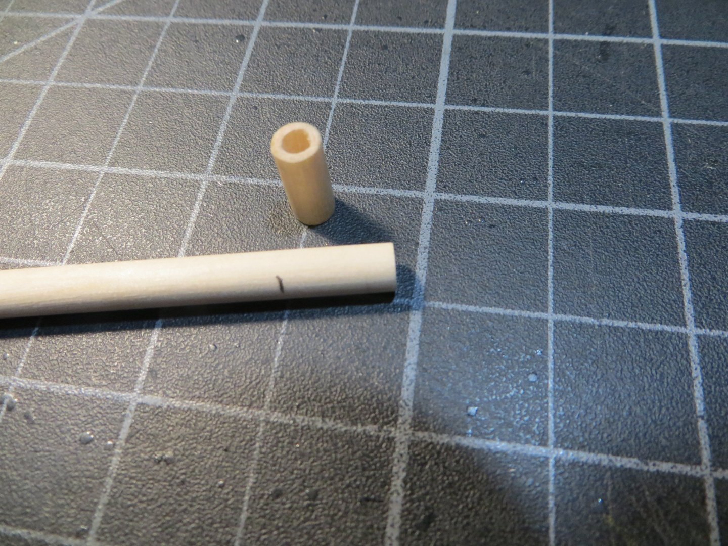
Elm Pumps I’ve been working slowly on my Rattlesnake. However, playing golf has been getting more of my time the last month or two. But I do have some progress to share. I’ve completed the two Elm Pumps. I decided to scratch build the Elm Pumps rather than use the Britannia metal ones from the kit. The blueprints say that it is made from an elm tree log that is cut into an octagon. I thought I could make pretty good-looking ones from a 3/16” dowel and not worry about it being an octagon. I started out by cutting two 7/16” lengths off a 3/16” dowel. Next step is to hollow out the center of the top half. I used my pin vise with a smaller bitt, then increased the diameter slowly. I stopped when I got to 3/32” and used a round mini-file to make the hole smooth. I made the pump handles from one of the wooden toothpicks I use to apply glue! This seemed to have the correct thickness. I sanded it into shape. I cut a strip of thin brass sheet to make a bracket holder around the top. This was blackened using the same chemical used on the cannon barrels. The biggest challenge was figuring out how to make a bracket to hold the pump handle. I came up with an idea to flatten the ends of a length of annealed steel wire using a small flat head hammer. This was bent into shape so one end could be glued to the dowel and the other end to the wooden handle. The brass band was glued around the top of the elm pump to help hold the bracket. Lastly, a couple of finishing touches. A piece of the same annealed wire was cut and bent to simulate the plunger. I just let it hang into the hollowed-out hole. Another piece of wire was inserted near the bottom of the dowel to look like a spout where the water comes out of the pump. Sorry I didn’t take any pictures as I made these pieces. But here is what they all looked like before assembly. The wood is stained with Dark Walnut. I wanted these to look different than the other pieces on the deck. Here is the assembled elm pump. A clothes pin holds it together while the glue dries on the pump handle and bracket. The pair of finished pumps. They are a bit top heavy! I will glue them to the deck a little later. I'm finishing up the Binnacle right now. I will follow-up with another post when it's done. Thanks, Ed

-
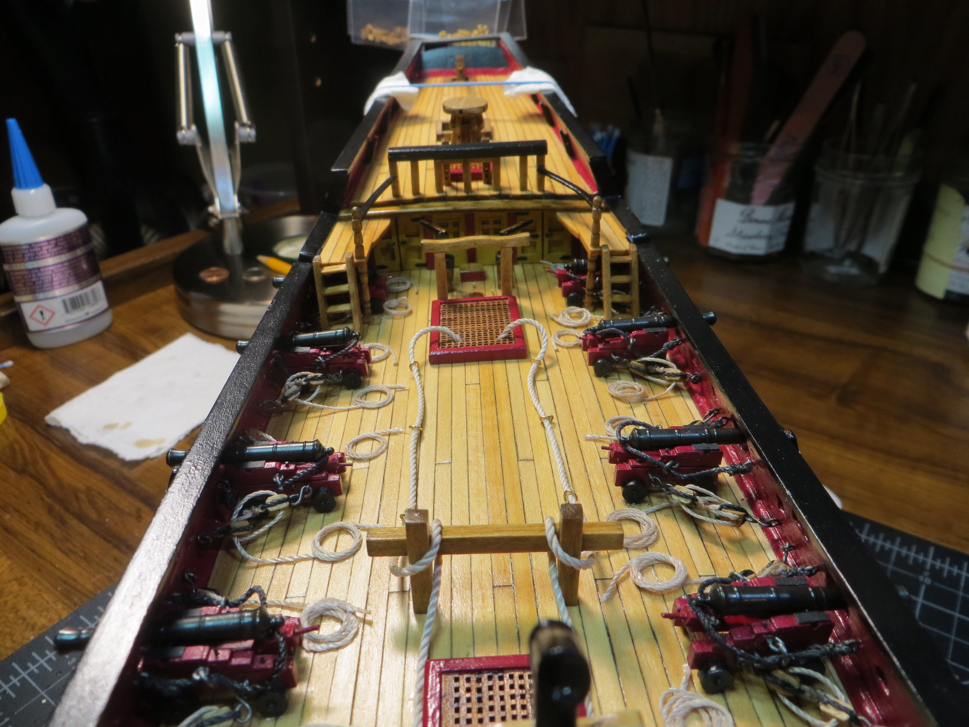
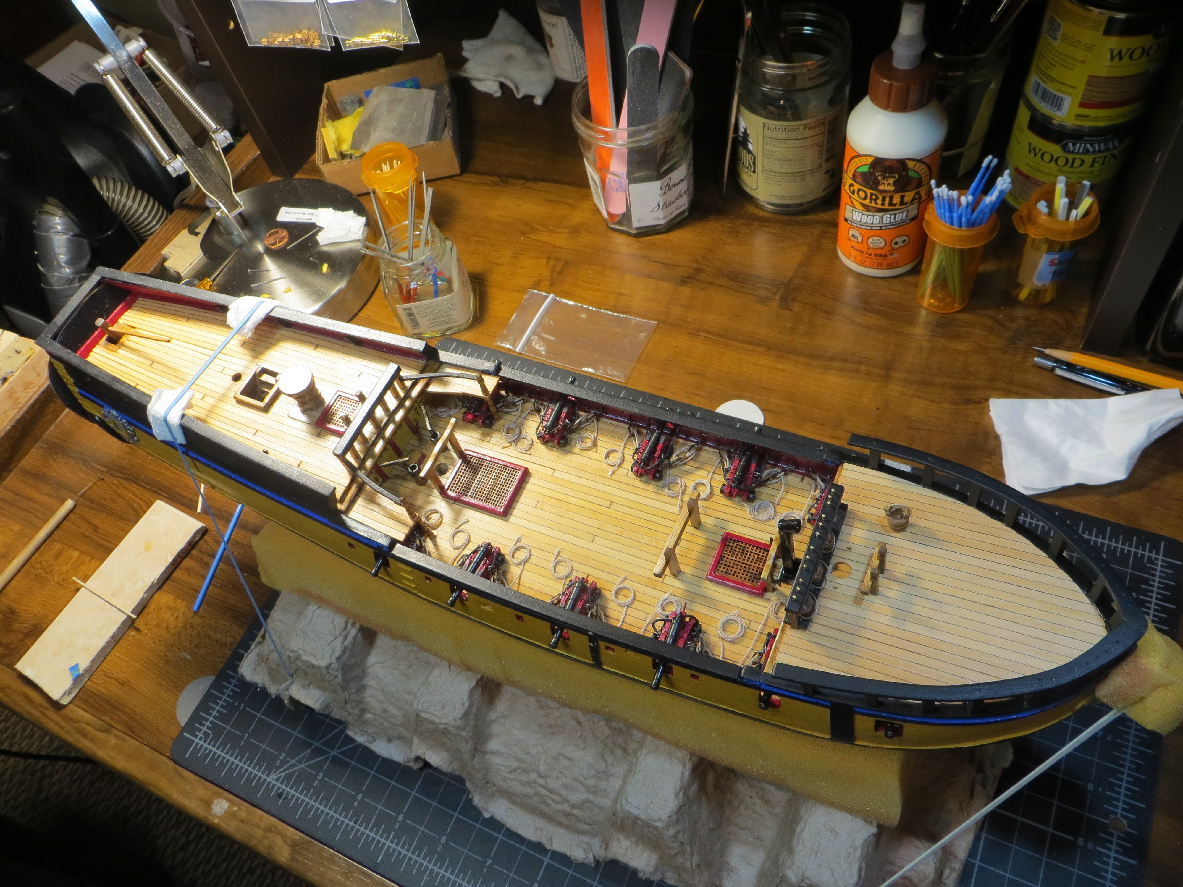
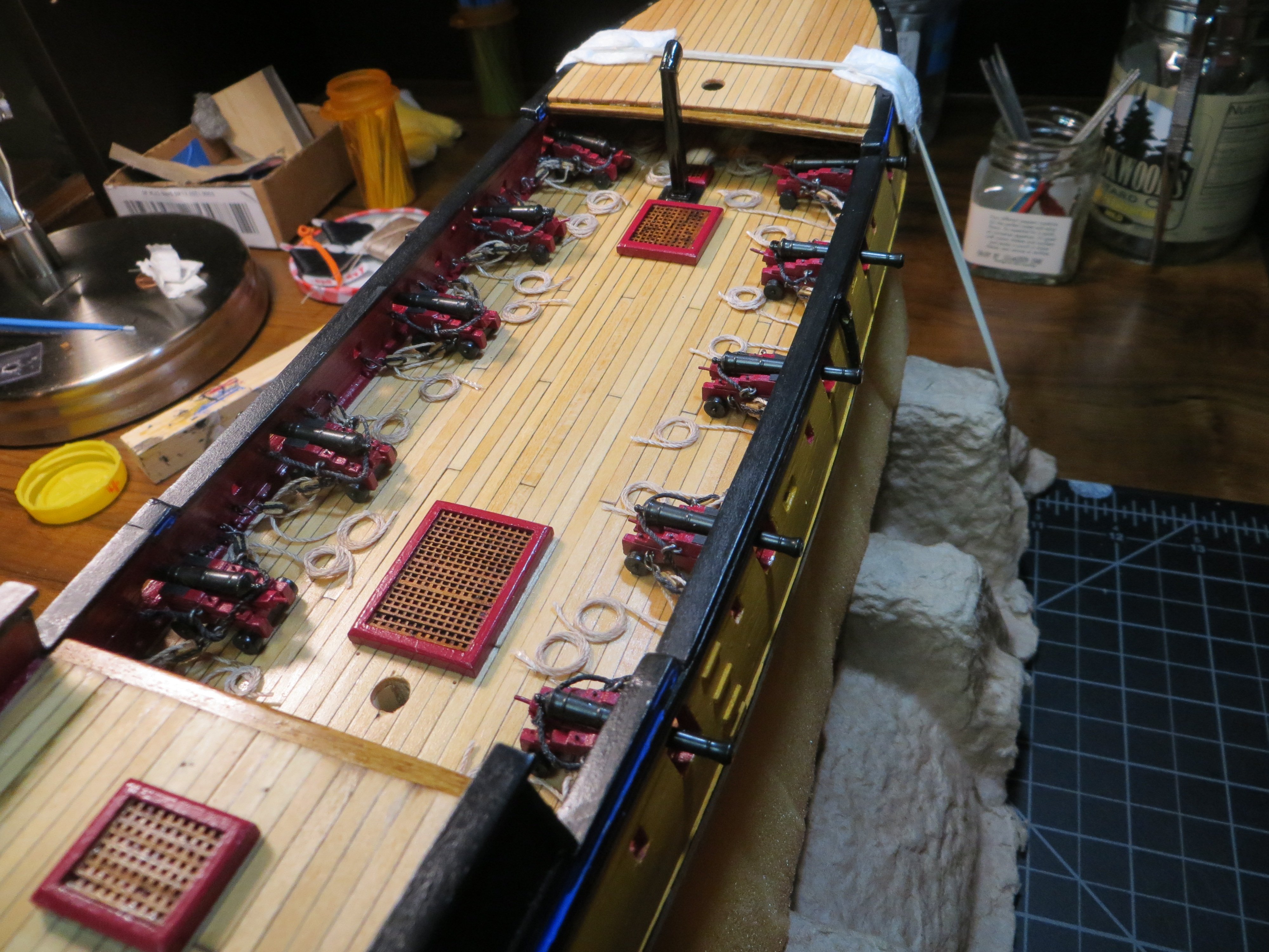
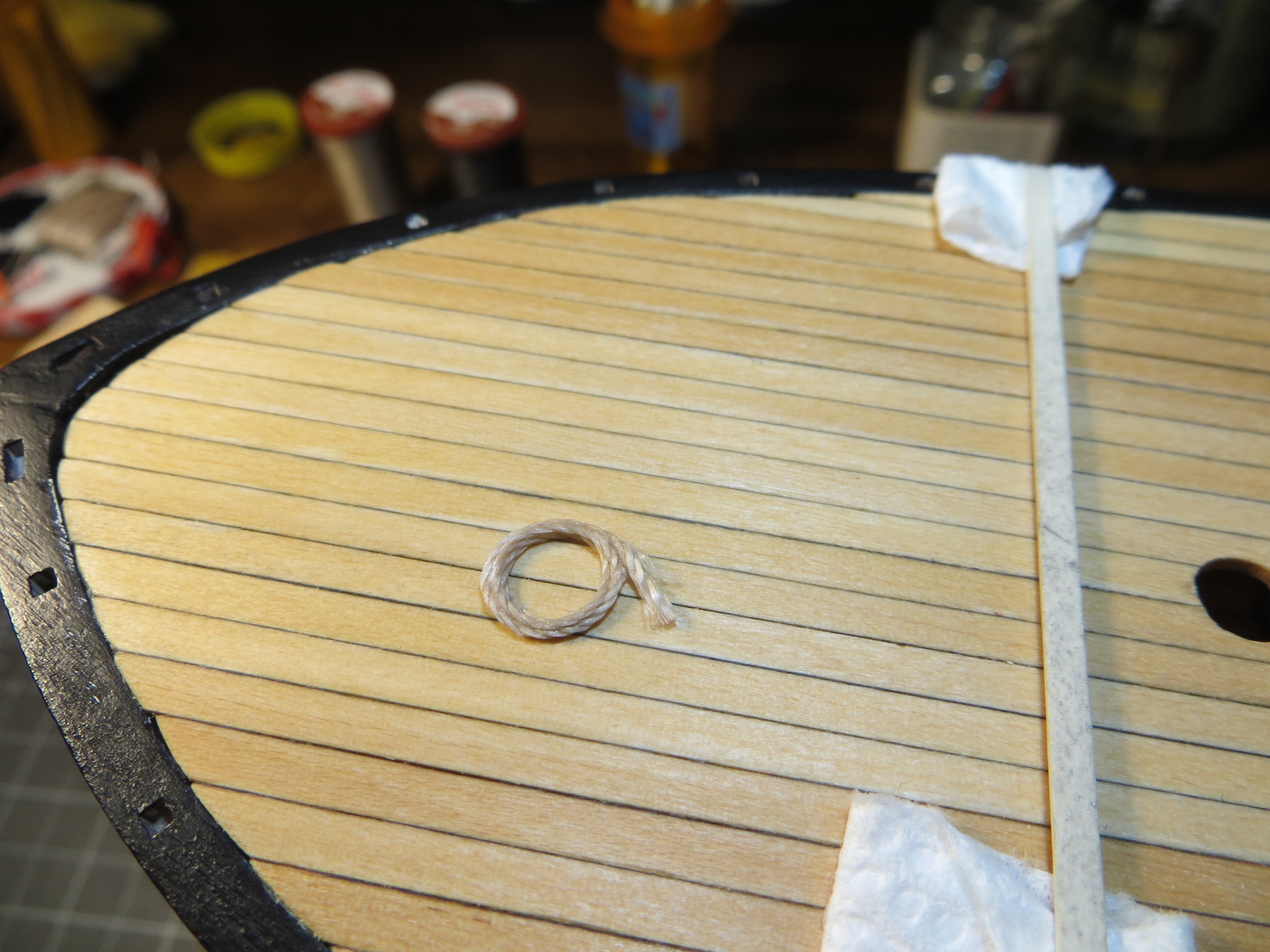
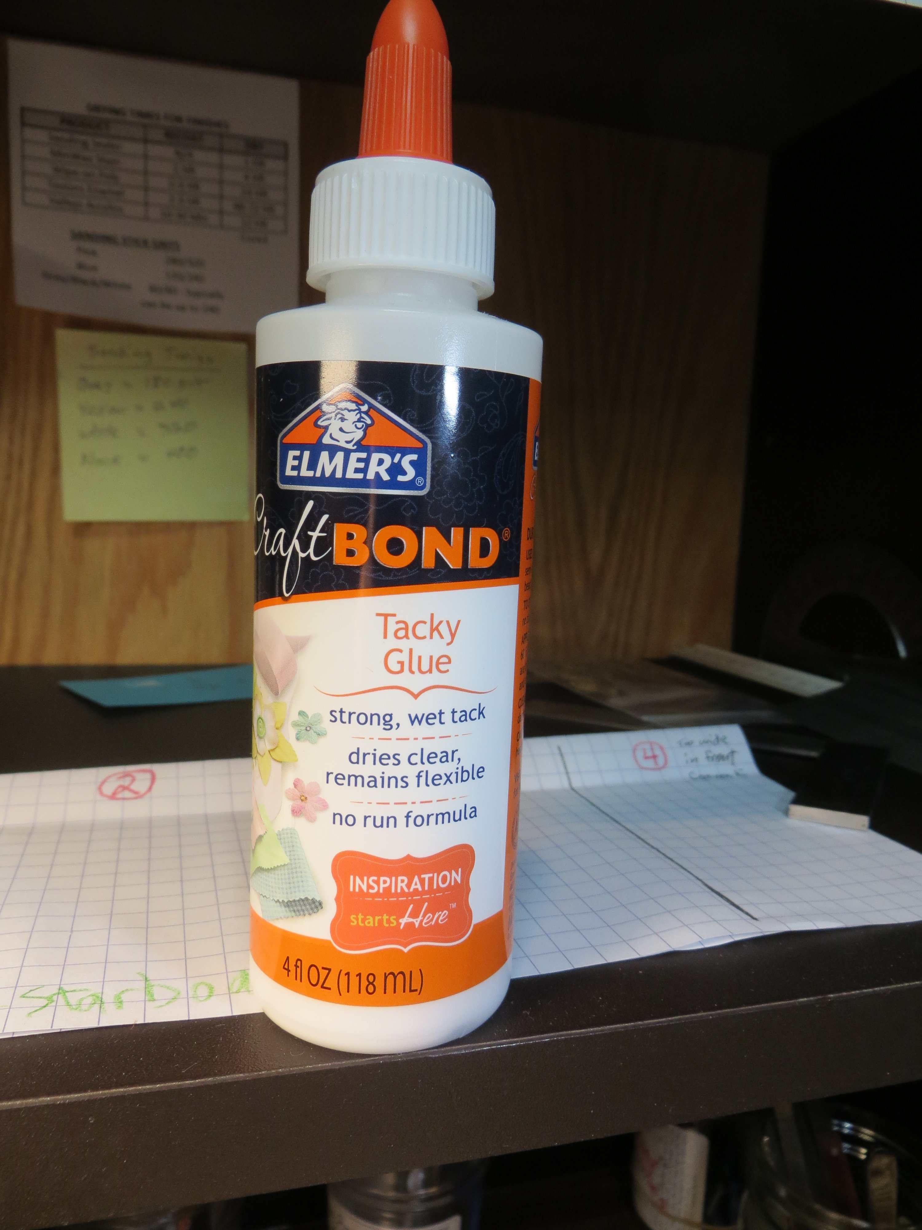
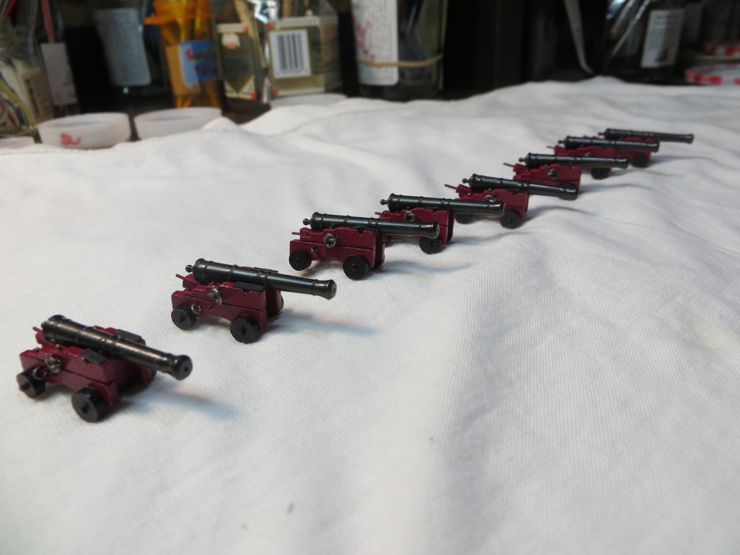
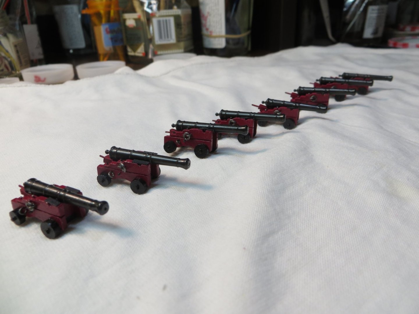
Rigging & Installing the Last 8 Cannons Seems like it’s been a long time since my last post. It’s been a slow grind! Well, after 50+ hours and 45 calendar days (not counting a vacation) I finally completed the rest of the cannons! Wow, this was some tedious work. I already detailed how I rigged the cannons when I did the first 4 that fit under the forecastle deck. You can check this out in my post #163. This was just more of the same times 8! I did them in two batches of 4. I decided to place the first four on both ends of the open gundeck. In other words, a pair aft of the focsl deck and another pair in front of the cabin wall. This allowed more space to then set-up the center four. One thing I did not cover previously is how I made the rope coils. I found this to be a real challenging task. I kept trying different ways to make them and finally settled on something. Below is a picture of the jig that I made. I found that the top end of a cheapo ball point pen had just the right diameter. Also, the glued coil could be slipped off without too much effort. The black piece of plastic in the below pic is the cut-off end of the pen. I drilled a hole in a piece of scrap board and also cut out a piece of clear plastic packaging to work on so the glue did not stick to the wood board. I fit the black plastic through a hole in the clear plastic and pushed it into the hole in the board. I cut about a 4” length of medium size rigging line. The starting end is taped down to the clear plastic. I kept spreading dilute craft white glue to the rope as I loosely coiled it around the pen base. I tried to keep the rope flattened down, rather than letting it wrap up the side of the black base. Then I taped the other end down. I did not allow the glue to dry completely. This made it too difficult to get off the jig without messing up the coil. I gave it about 30 – 40 minutes to partially dry. I carefully pulled the black pen base out of its hole and slipped the coil off the end. I set it aside so it could dry completely. I cut off the bottom end of the rope, so it was not visible. Here is the finished rope coil Here is a close up of the coils glued to the deck. I started by gluing the end of the rigging line to the deck and then glued the coil on top of it, so it looks like one continuous piece of rope. Here is the glue I used. A lot of people use diluted PVA glue. This is basically that. But it requires no diluting. I tried diluting this stuff, but it did not hold as well or dry as fast. I like this glue because it does not make the rope look all stiff and dark looking like CA glue does. Here are the finished cannons on the gundeck Hope you like the cannons! I’m planning my next steps. I intend to work on the other pieces for the deck, like the Elm pumps, Capstan & Binnacle. I want to scratch build these rather than use the Britannia supplied kit stuff. Thanks for looking in, Ed


-
Hi Gregg, Checking in on your Bluenose build log after you referenced me in your last post. Very nice work! Your rigging is coming along nicely. I agree, the brass fittings look really sharp on this schooner. I'm blackening the brass on my current Rattlesnake model. Brass didn't seem right for a late 1700's pirate ship. Bluenose was my first ship and I learned a lot from it. Glad my log has been helpful for you. Keep up the good work! Ed
- 184 replies
-
- 1
-

-
- Bluenose
- Model Shipways
- (and 1 more)
-
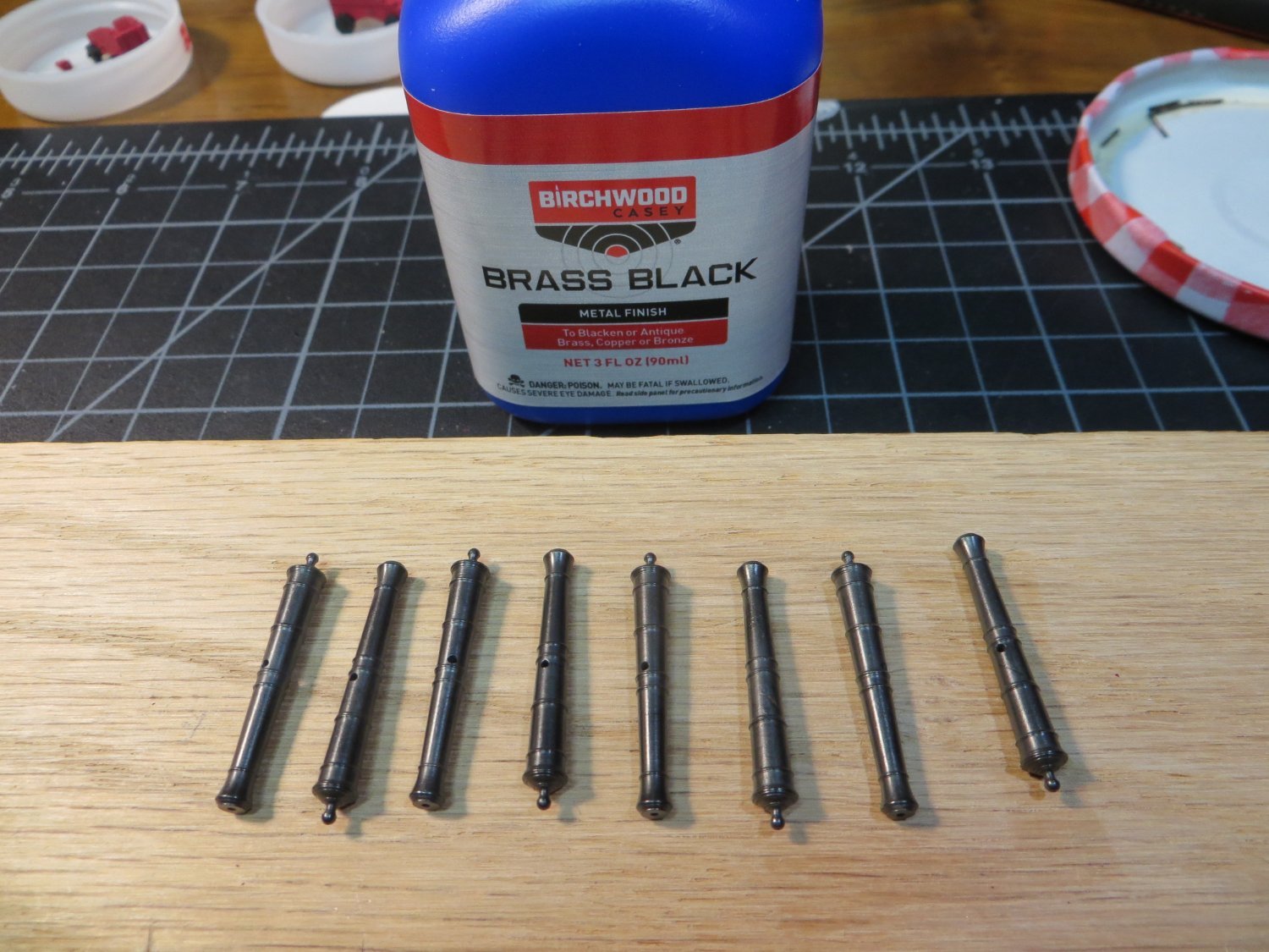
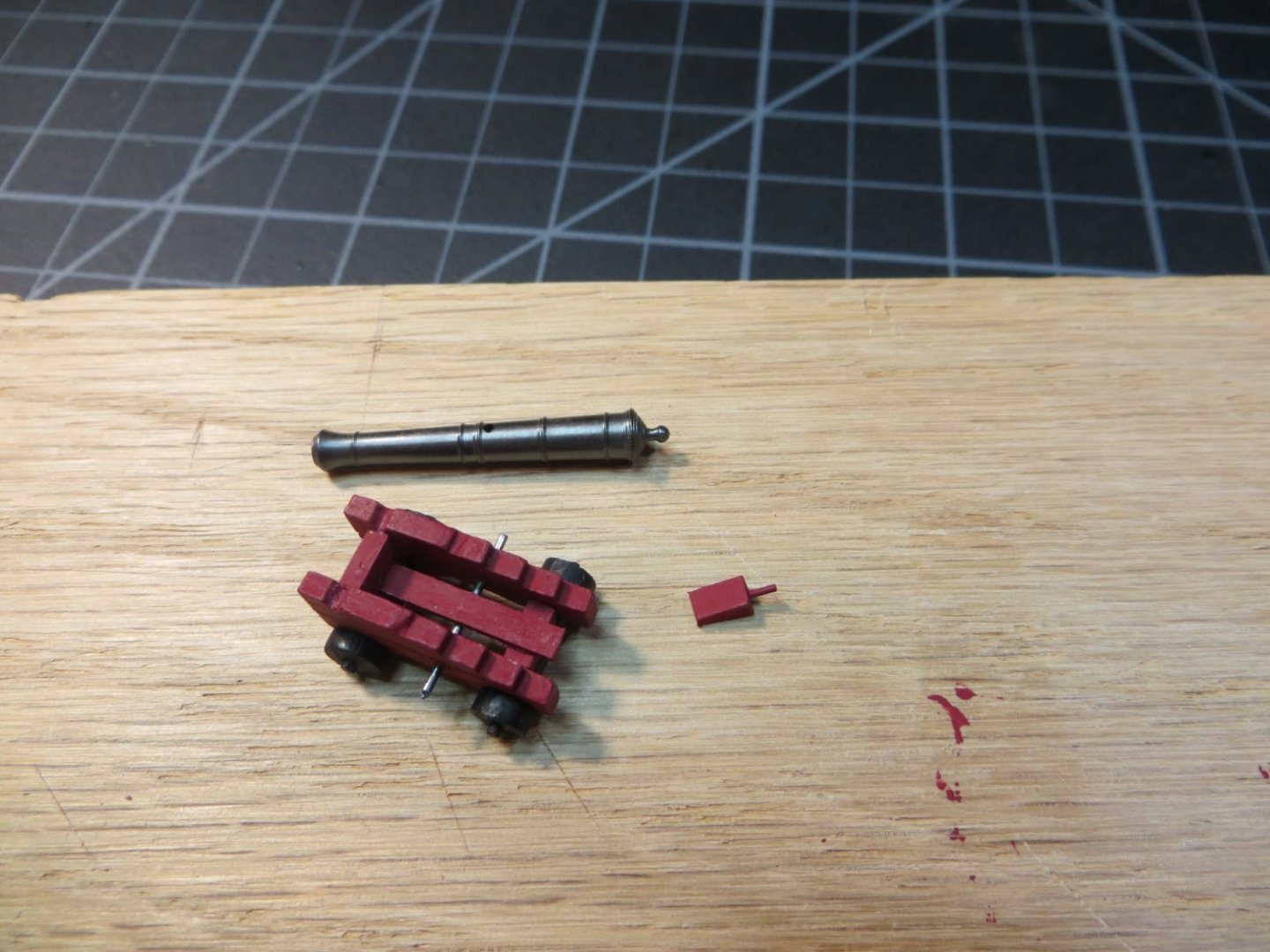
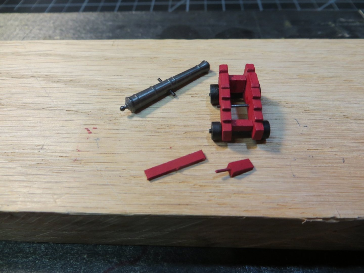
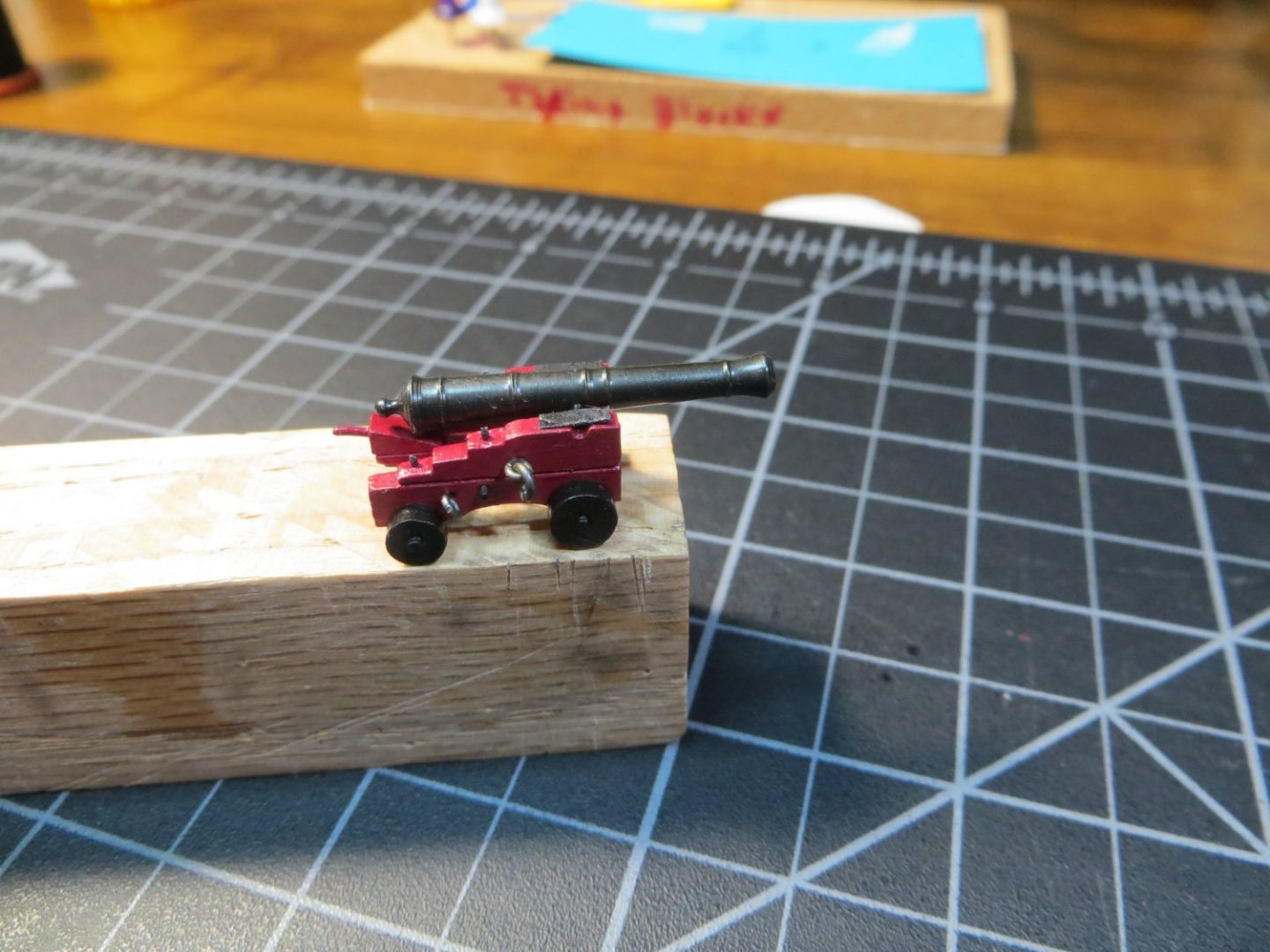
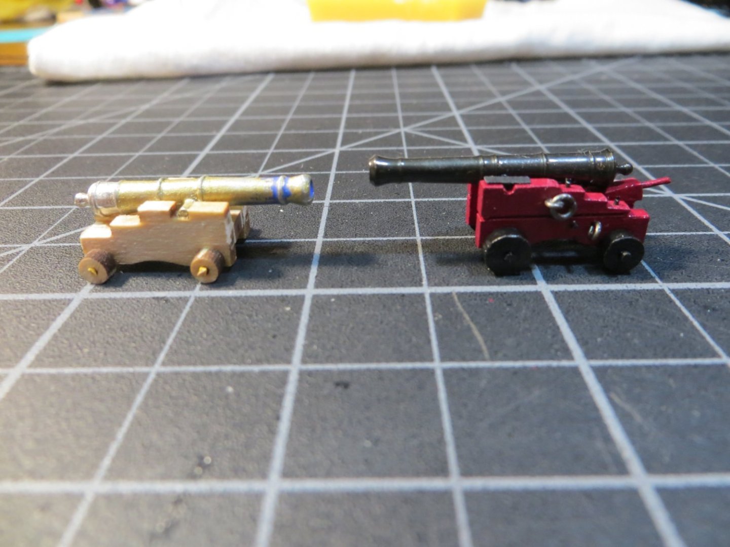
Completing the final 8 Cannons for the Gundeck While there is still open space to work on the gundeck I decided it was a good time to build and install the last 8 cannons. I made 4 cannons that are under the Focsl Deck several steps ago. at that time, I did not go into any details on how the cannons are made. This time I thought I would write-up something for anyone who is thinking about using the Syren Ship Model Co. cannons and carriages. I don’t know if I’m just slow or really anal, but it took me 50+ hours and the month of March to make these 8 cannons. There are a lot of details involved with these beautiful cannons. This post will only cover the assembly of the carriages and cannon barrel. I am just starting on the rigging now and will provide another post when I’m done. I decided to make them in two batches of 4. For the most part, I performed each step on all 4 of them at the same time. When I get a technique and a rhythm going, I like to keep it rolling! Here are all the carriage parts after removing them from the laser cut sheets. Laser char has also been removed. First thing I did was to deepen the grooves for the cannon barrel and axles with files. This was necessary to make them fit the height of my gun ports. Chuck’s instructions suggest scribing a cut into the sides of the carriage frames to make it look like an upper & lower half are bolted together from the top. Below I drew a pencil line with the square to mark the line I used a razor saw to make the cut along the line. On my first four that are under the Focsl I thought the cut wasn’t wide enough to see. So, this time I used this fine point punch to make the line a little thicker. The axles come in two sizes. The shorter one goes in front with the larger wheels. The carriage is wider in the rear, using a longer axle. The part where the wheel fits on needs to be sanded into a rounded shape. Must be careful not to sand it too much. I made mine with a tight fit. Next is the “Quoin”. The wedge-shaped block used to raise and lower the cannon. I sanded mine smaller to accommodate the height issue. The handle is supposed to be turned using a Dremel to give a piece of wood the shape of a belaying pin. I didn’t like the way these turned out for me. So, I just used a short length of annealed steel wire and painted it. Another piece of this wire is used to hold the carriage sides together. The bed sits on this wire too. I substituted a 1/32” x 3/32” piece of stripwood to make the bed shorter. I painted all the parts before assembling them. Red for the carriage and black for the trucks & axles. Here is the assembled carriage. I placed a drop of thin CA glue into the hole to hold the wire in place before snipping off the ends. A bit of the end is left sticking out to simulate a bolt. I treated the brass cannons with this Brass Black metal finisher. It took two applications to get them looking evenly treated. After wiping off the residue from the chemical (twice), I used a cloth buffing attachment in the Dremel to polish them to this finish below. I think this looks more realistic than using black enamel paint. Several finishing touches make the gun look pretty awesome. A couple of more wire “bolts” are inserted on top of each side frame. Tiny strips of black card stock are glued on to look like plates holding the barrel in place. And finally, 4 eye bolts and 2 rings are attached for use with the rigging. 1 month later the arsenal is ready for rigging and installation on the ship! Just for the sake of comparison, on the left is the kit supplied cannon. Obviously, it’s not finished, but you get the idea. Also, I’ve read that the brass black does not work on Britannia metal. If you do decide to use the Syren cannons, build your gunports a little taller so they will fit more easily. These are supposed to be the right scale, but you can see how the kit ones are shorter and squattier. Hope this information is helpful for someone out there! Next up is rigging the cannons. Thanks, Ed


-
Hi Gregg & All, I'm happy to see that you have found my Bluenose build log to be helpful to you with your own build. I really enjoyed building Bluenose and creating the log. I continue to be active on model ship world with my current build of the Rattlesnake. Feel free to contact me if you have any questions about my Bluenose log. Thanks, Ed
- 184 replies
-
- 1
-
-
- Bluenose
- Model Shipways
- (and 1 more)
-
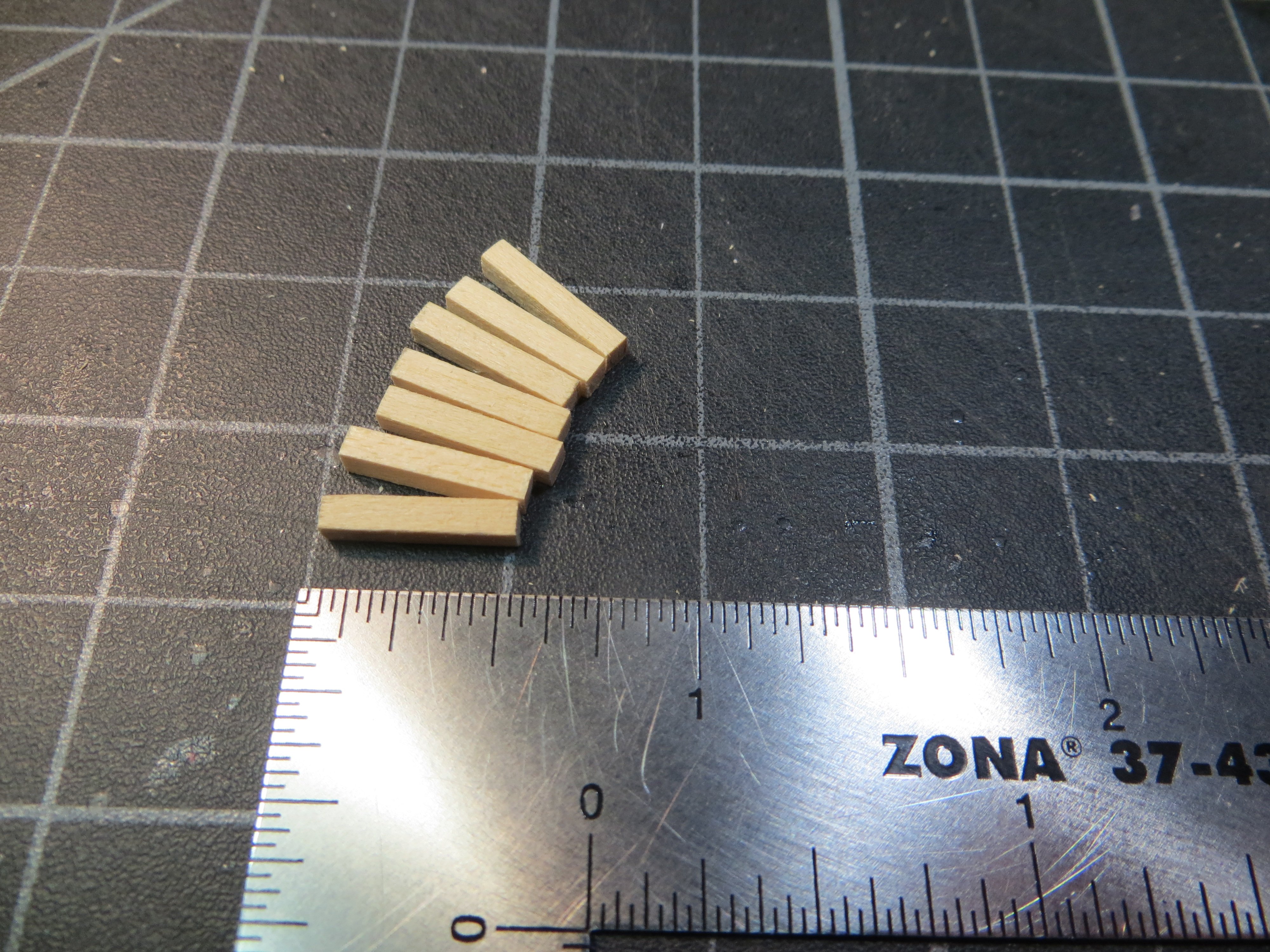
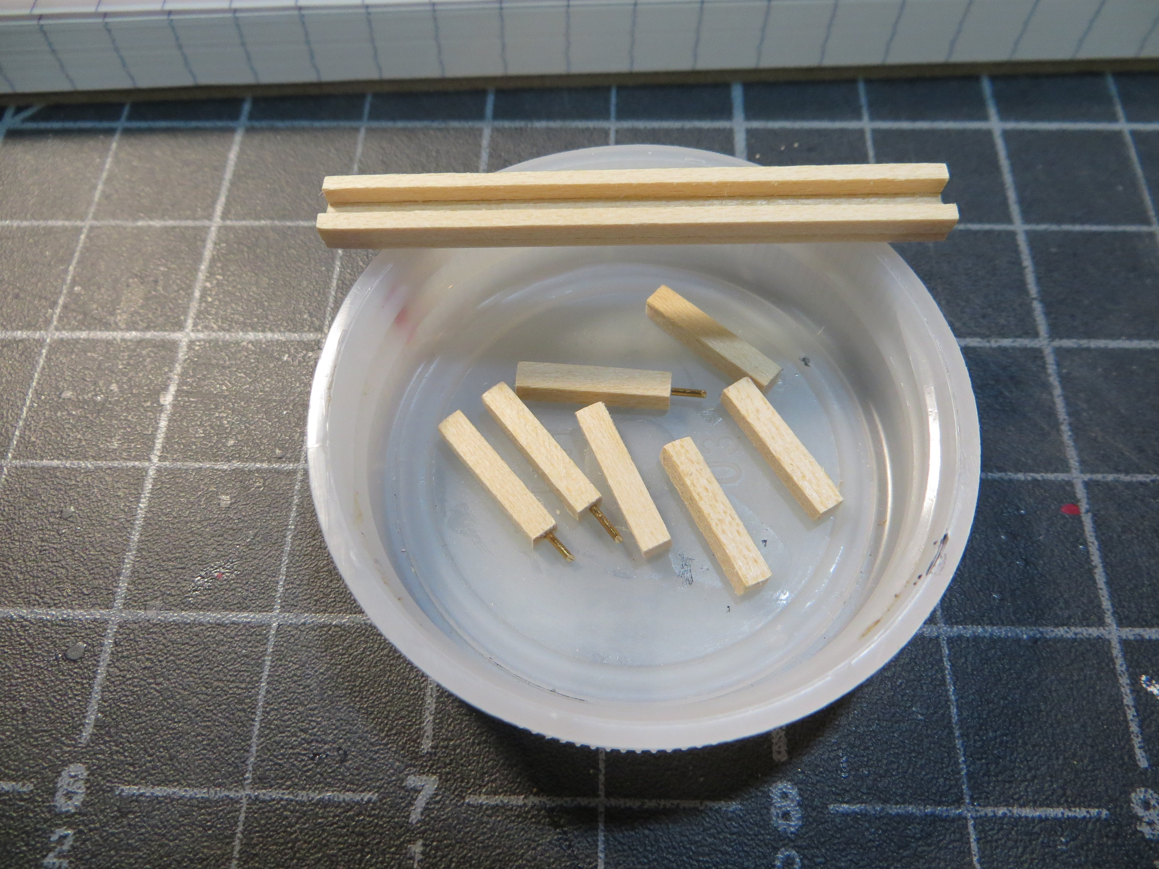
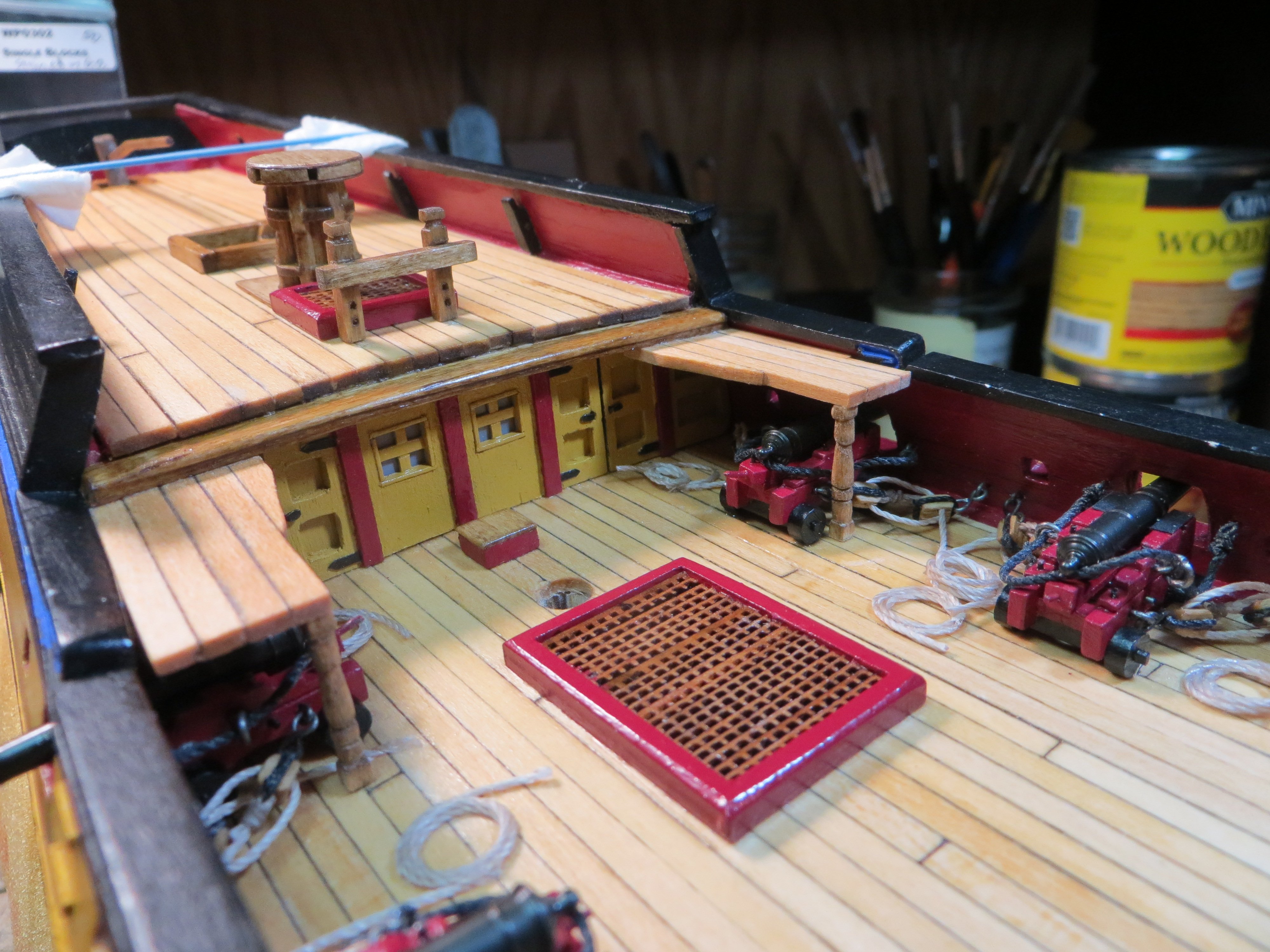
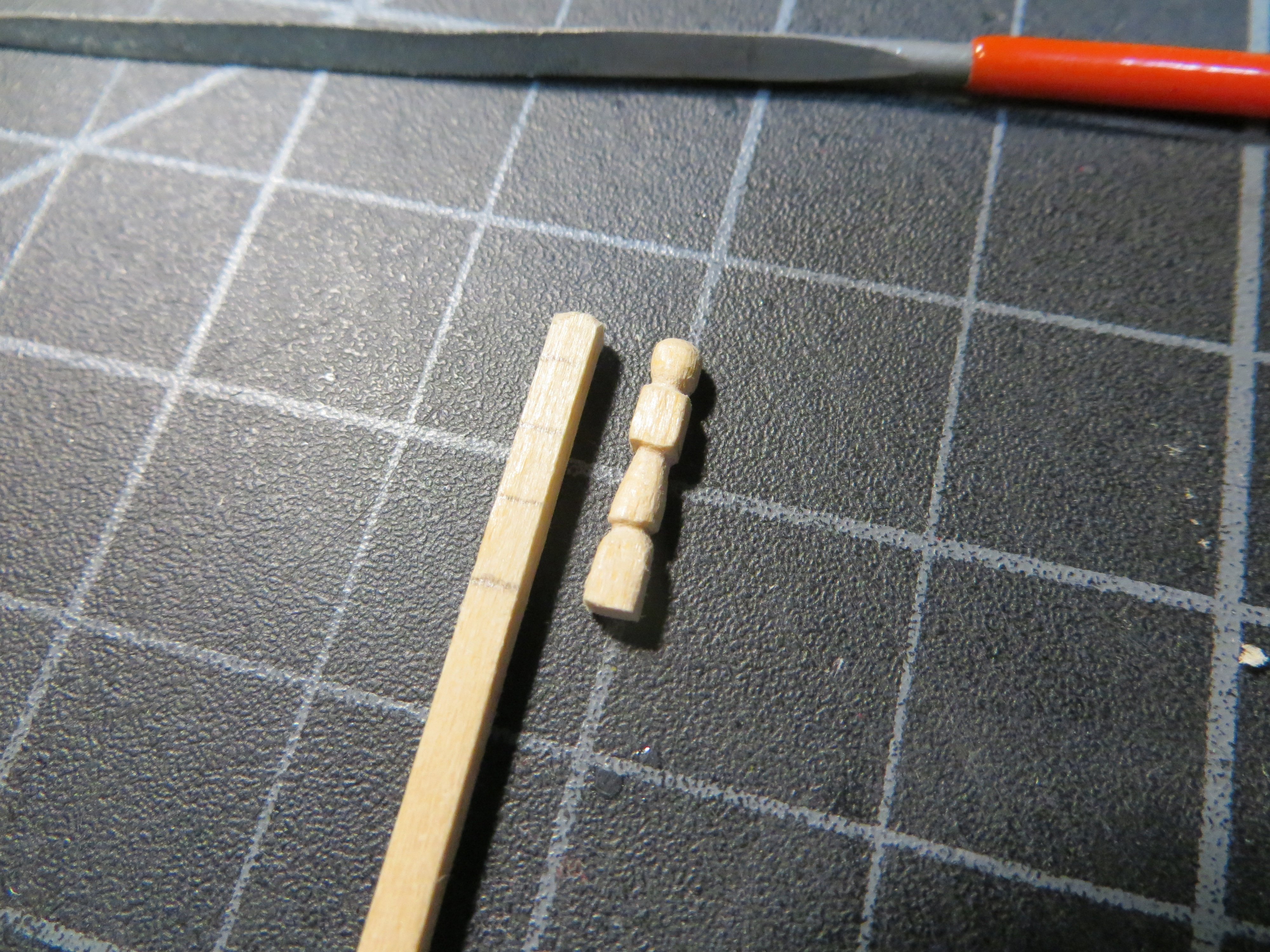
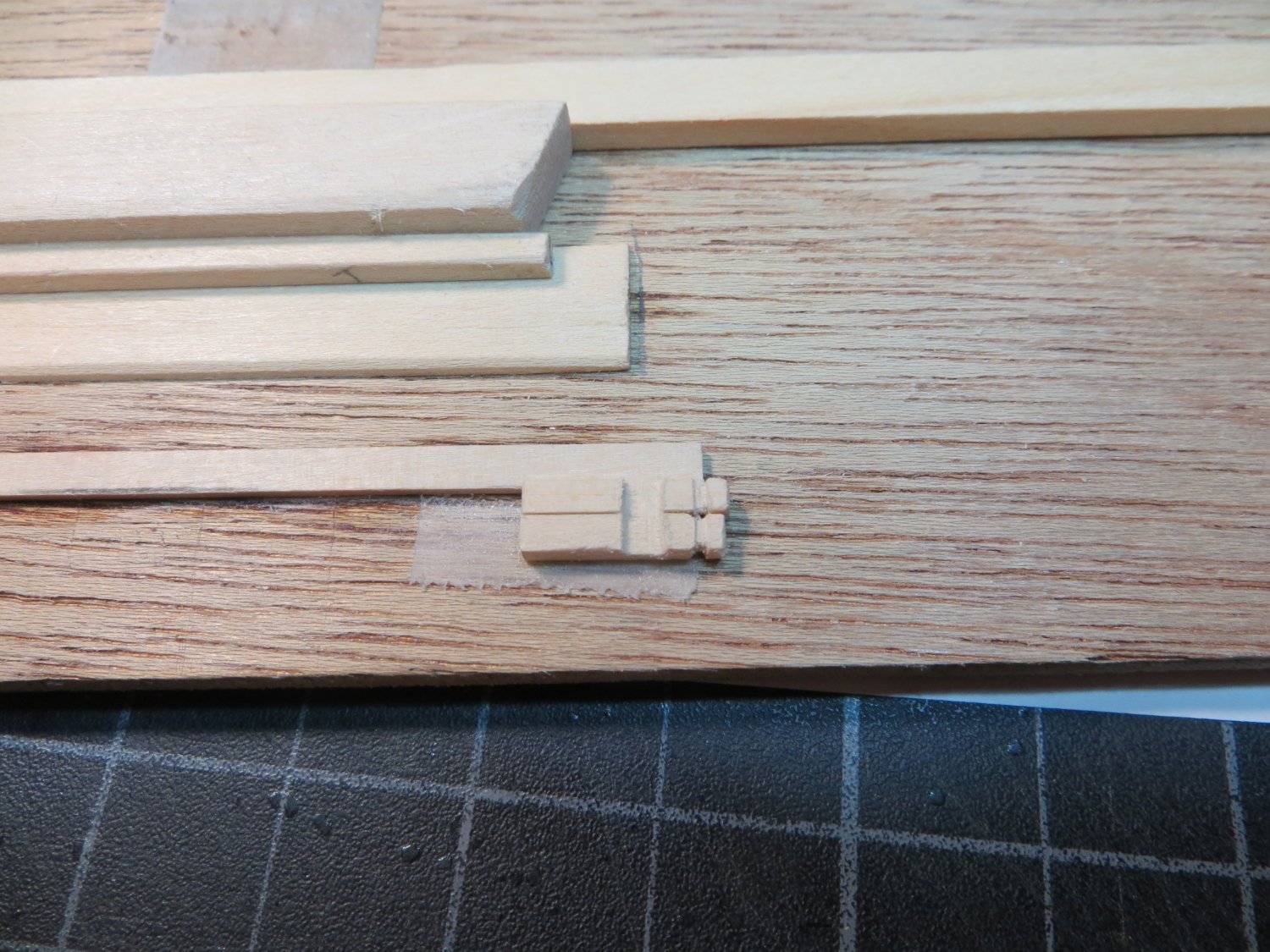
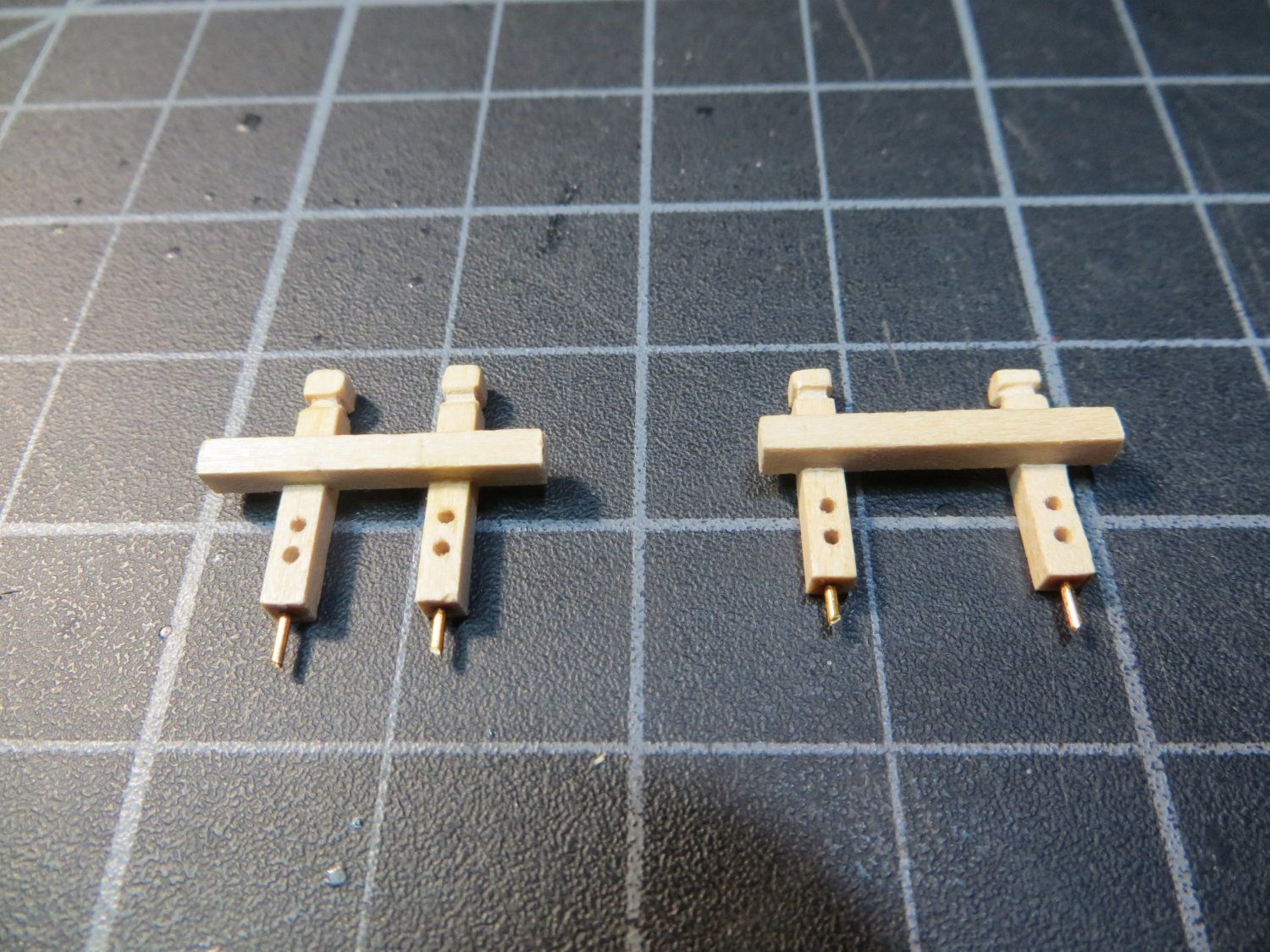
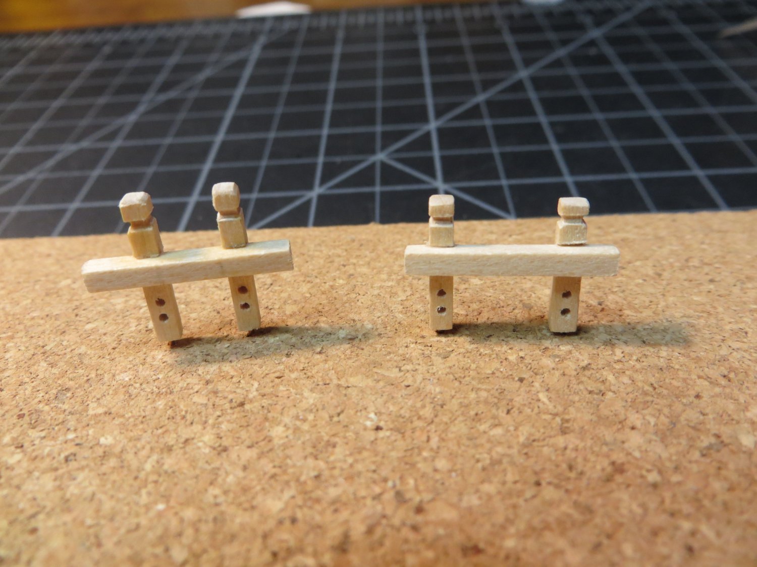
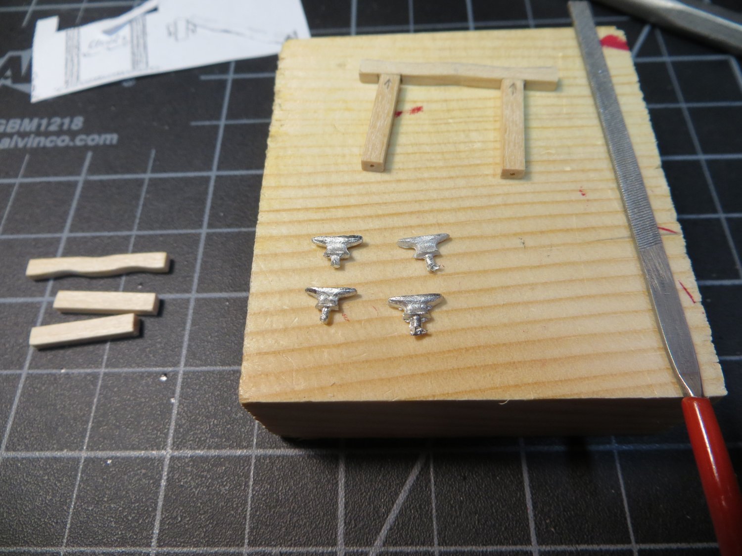
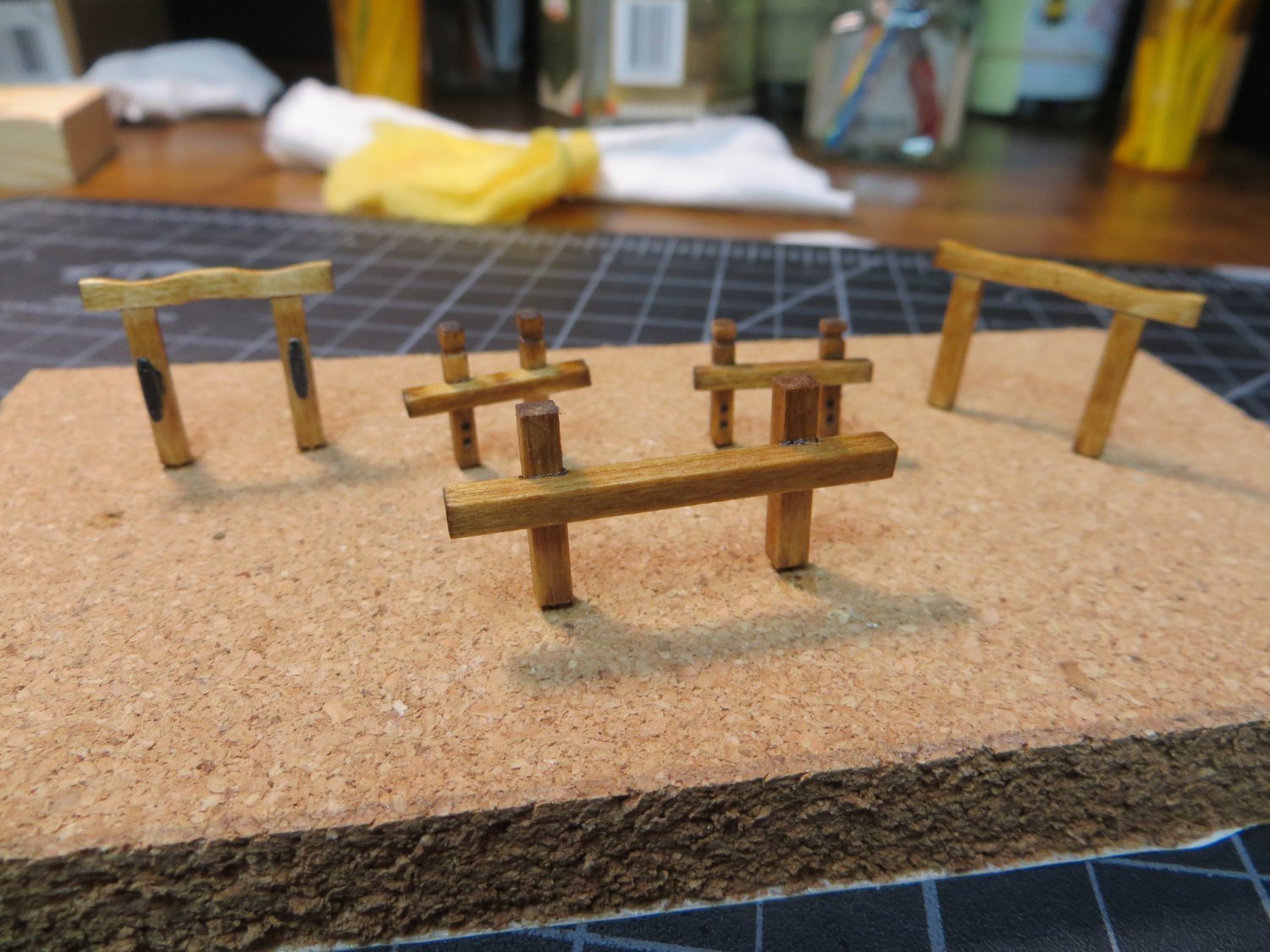
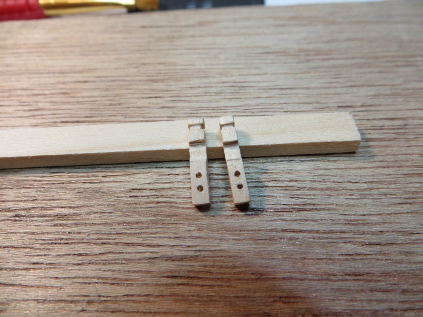
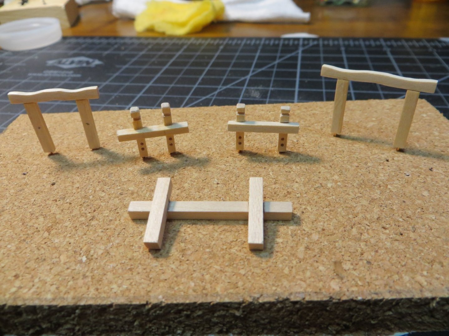
The 5 Bitts I just completed the Bitts. There are five Bitts on the Rattlesnake. These pieces are provided in the kit as Britannia metal castings. 1. Topsail Sheet Bitts – stand in front of the fore mast on the focsl deck 2. Fore Gallows Bitts – stand behind the galley stack on the gundeck. It holds the spare yard arms that the long boat sits on 3. Riding Bitts – stand under the long boat. This one has a short, thick pair of posts. It is used to secure the anchor line when the ship is at anchor 4. After Gallows Bitts – stand before the main mast. It holds the aft end of the long boat 5. Fore Brace Bitts – stand right behind the bulkhead beam of the quarter deck I don’t like the metal castings for these. I don’t think it will be difficult to kit-bash these out of stripwood. The hardest part is finding the right size pieces of wood to use. The measurements for the cast metal do not match what’s in the plans anyway. I’m not going to get too worried about an exact match. I made all my measurements from the blueprint plans. For anyone who is interested, here is the process I used. Topsail Sheet & Fore Brace Bitts: Both of these are very similar in design and size. The cross beams are both approximately ¾” wide. The Topsail bitts posts are shorter @ 7/16” and they are closer together. The Fore Brace bitts is taller @ ½” and the posts are spread wider apart. They both require holes in the posts to simulate sheaves. I used 3/32” square stripwood to make all these parts. · Measure and cut the 3 pieces of wood for each · I cut the posts 3/32” longer to make a decorative carved top. I got this idea from David Lester’s Rattlesnake build. · I carved out the top first using mini-files & then cut the post to length · Filed out a notch where the cross piece needs to fit into the posts. I have a file with the right width! · Drill holes for the sheaves with a pin vise · Drill a hole in the bottom of each post and CA glue an artistic wire pin to secure them to the deck · Glue the parts together · I stained all 5 of the completed bitts at the end using Minwax Golden Oak. 3 coats to deepen the color Fore & After Gallows Bitts: Both of these are the same in design. The Fore Gallows is narrower than the After. Also, the fore gallows have cleats on the fore & aft sides of both posts. The After Gallows has no cleats. Use 3/32 x 1/8” stripwood for both cross beams. I selected the wider 1/8” strip to allow for the curved shapes that need to be sanded into the cross beams. Measure and cut the 3 pieces of wood for each · The top cross beams require some curves to be sanded in on both · Drill a hole in the top and bottom of all the posts to insert pins that will act as dowels to anchor the cross bars and secure the bitts to the deck · Prepare kit supplied Britannia cleats. (Left pair filed and ready; Right pair just out of their bag) · Glue the parts together Riding Bitts – This is a shorter but more “massive” bitt for holding the anchors! Use 1/8 x 1/8” square stripwood. The cross beam is inset into notches on the posts. The steps are similar to the topsail bitts, except there is nothing additional required. The 5 Bitts are ready for staining Bitts after staining. Note the cleats on the Fore Gallows Bitts in the upper left corner. I think mine are better looking than the metal ones from the kit! But I’m biased!! I plan to build, rig & install the last 8 cannons before I attach the assembled Bitts to the decks. I need room to work. I did glue down the assembled hatches, since these are low and will not be in the way. In fact, I need to know where they are located when I lay down the coils of rigging ropes for the cannons. I also attached the pad for the galley stack and the galley stack on top of it. The plans show this skewed toward the port side. A hole was drilled first through the pad and then through the deck after the pad was glued down on the deck. I used thick CA glue to attach the stack. Here is a pic of the ship at the current time. My next step is to work on the remaining cannons for the gundeck. Thanks for looking in on my progress! Your comments & questions are always welcome. Thanks, Ed


-
Thanks Dave! I really appreciate your kind words. Ed
-
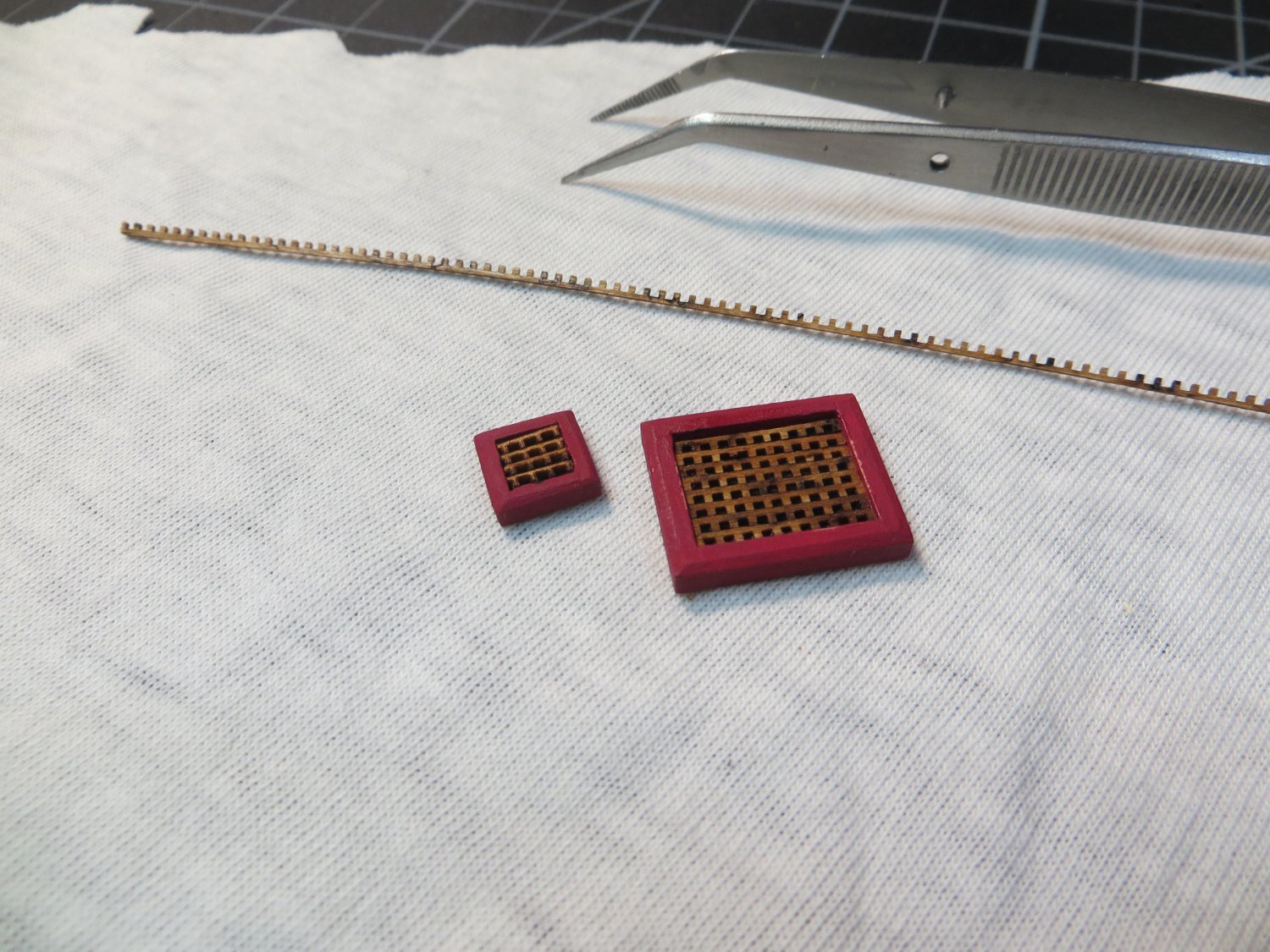
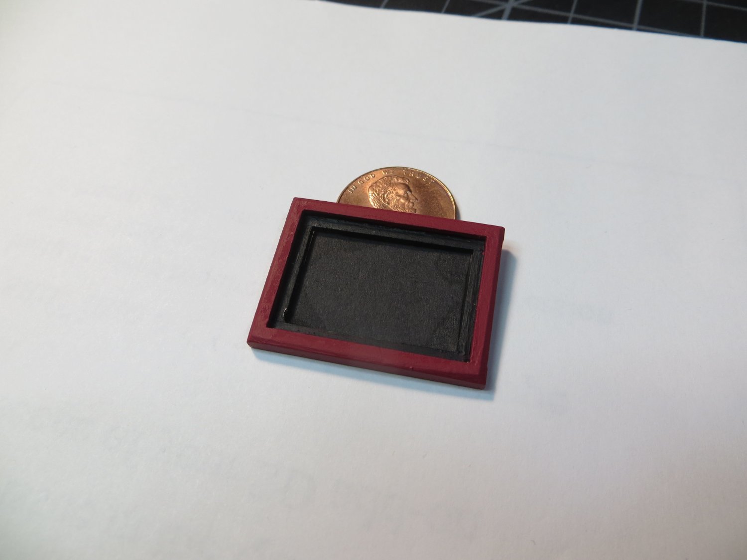
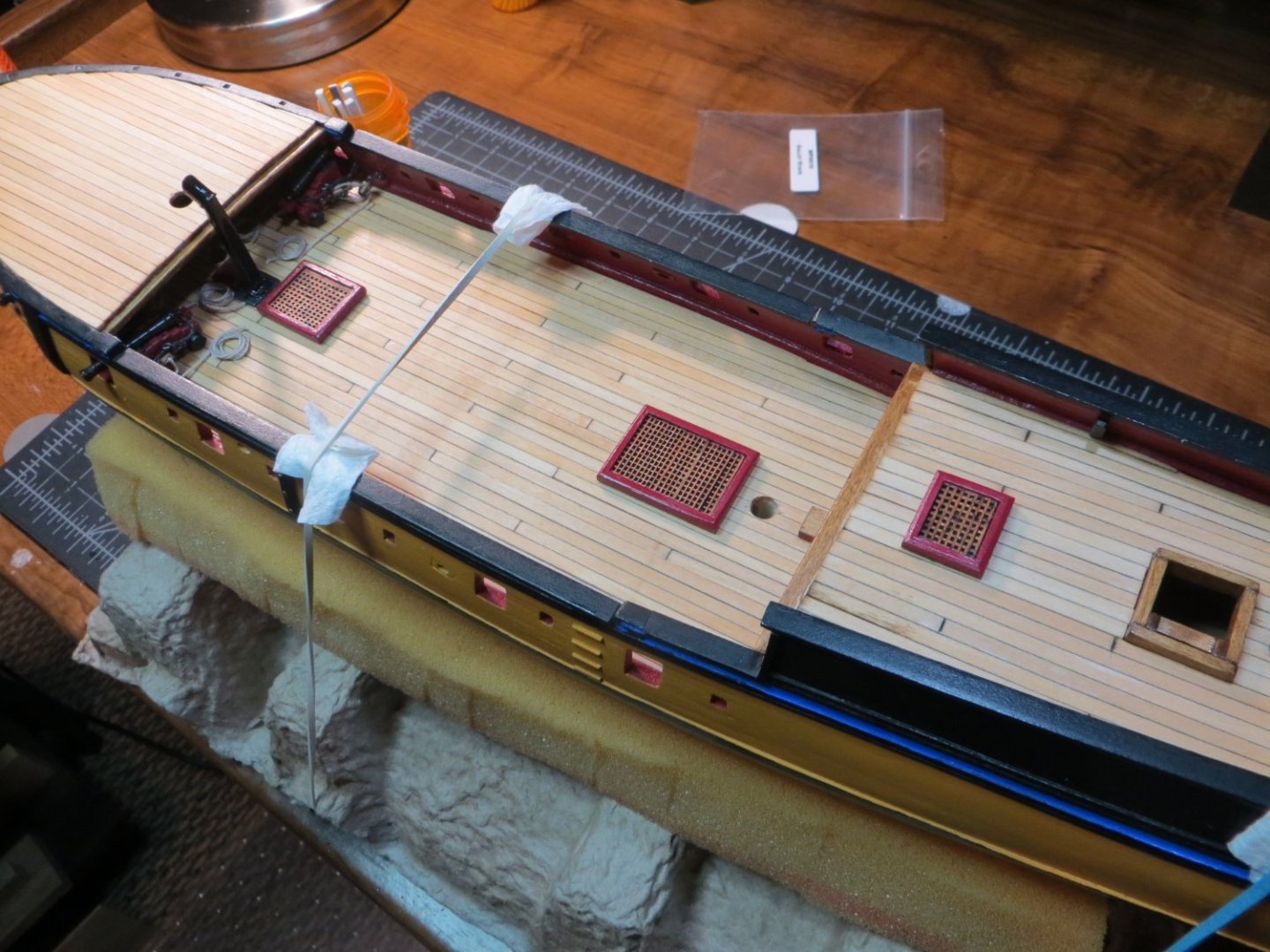
Hatches: Coamings & Gratings There are five Hatches with Coamings & Gratings on Rattlesnake. Back when I started planking the decks, I made a decision to glue the hatches on top of the deck, rather than building the deck around the hatches. I used 3/32”x1/8” stripwood for the large coamings. 1/16” x 3/32” stripwood for coamings #1 & #4. I sanded an angle on the top outside edge to smooth off the 90-degree edge. I painted the coamings red. The gratings in the kit are made of cherry wood. They will only be treated with wipe-on poly. Model Expo did not provide enough of the laser cut stripwood for the gratings. But, per my request t0hey sent me some extra at no charge. That’s a nice benefit with their models. Here is a list of the hatches starting at the bow and going aft. I did not add the one that goes under the Focsl deck. This space was mostly filled up with the fully rigged cannons. 1. Galley Steam Grating – located between the galley stack and the foremast. I used the smaller stripwood on this little grate. 2. 2nd Largest Grate – located aft of the Fore Gallows Bitts. It is nearly an inch long 3. Largest Grate – located forward of the main mast & aft of the long boat bitts. It is 1.25” long 4. Small Scuttle – located in front of the cabin wall. It has a solid cover 5. 3rd Largest Grate – located in front of the capstan on the quarter deck Here are the steps I used along with some pictures: Measure, cut & glue the outside frames according to the plans. I used this jig to make sure they had square corners. This important for the gratings to lay correctly. I used lap joints. I made all 5 at once, while I was on a roll. Measure and cut the inside ledges to hold the gratings. Use 1/16” square stripwood and made sure it was flush with the bottom of the coamings Sand down the outside top edge at an angle to smooth off the 90-degree edge Paint the coaming frames red. Paint the ledges black Cut and glue black cardboard under the gratings so it looks like the dark hold of the ship is underneath (instead of the lighter colored deck) Measure, cut with a #11 knife blade and sand the gratings to just fit the inside width of the coamings. Start at one end and lay the pieces in position. Place drops of CA glue around the outside edge to hold everything in place Cut a piece of 1/32” thick stripwood for the solid cover on the scuttle. Round the edges w/ a sanding stick. Stained the cover with Golden Oak Seal the assembled pieces with Minwax satin wipe-on poly. Mark the locations on the decks for each hatch. Glue them to the deck. I have not glued them down yet. They are only placed in position in the below picture. I'm going to wait until I make the Bitts before I start gluing. In fact, I may install the cannons before gluing the bitts. I want to have enough space to work on the cannons. It was challenging working under the focsl deck with those cannons! The next step is to make the Bitts. Thanks, Ed