HOLIDAY DONATION DRIVE - SUPPORT MSW - DO YOUR PART TO KEEP THIS GREAT FORUM GOING! (Only 20 donations so far - C'mon guys!)
×

Ed Ku20
-
Posts
230 -
Joined
-
Last visited
Content Type
Profiles
Forums
Gallery
Events
Everything posted by Ed Ku20
-
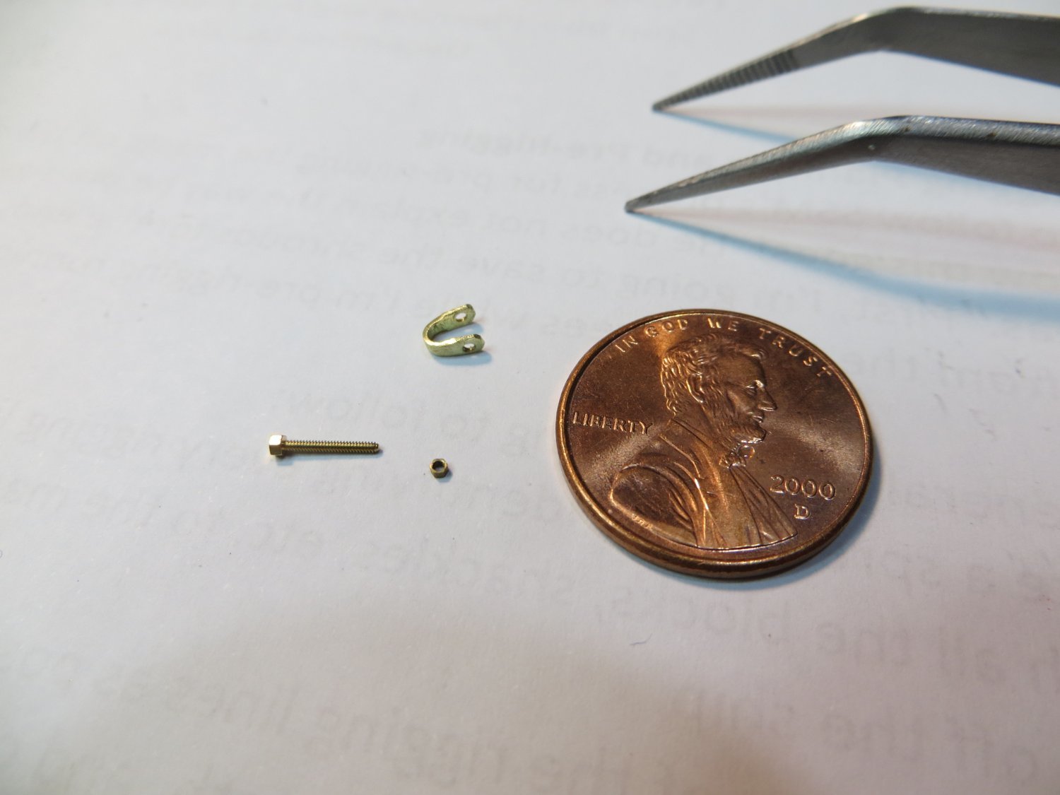
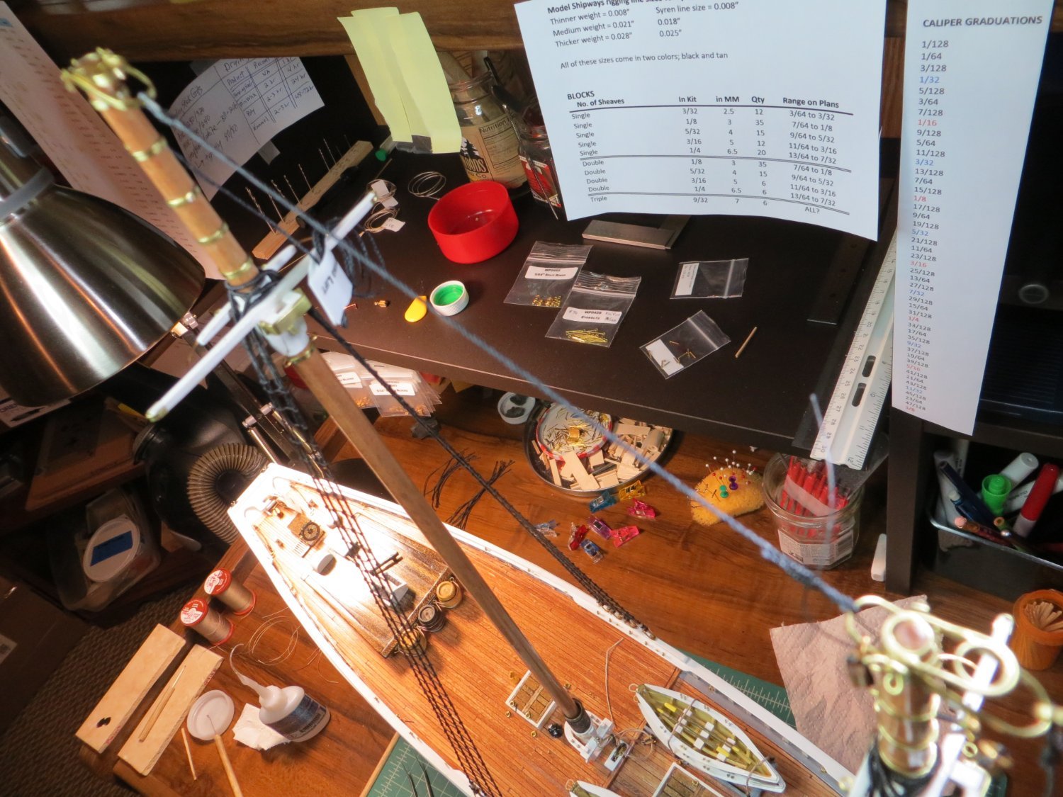
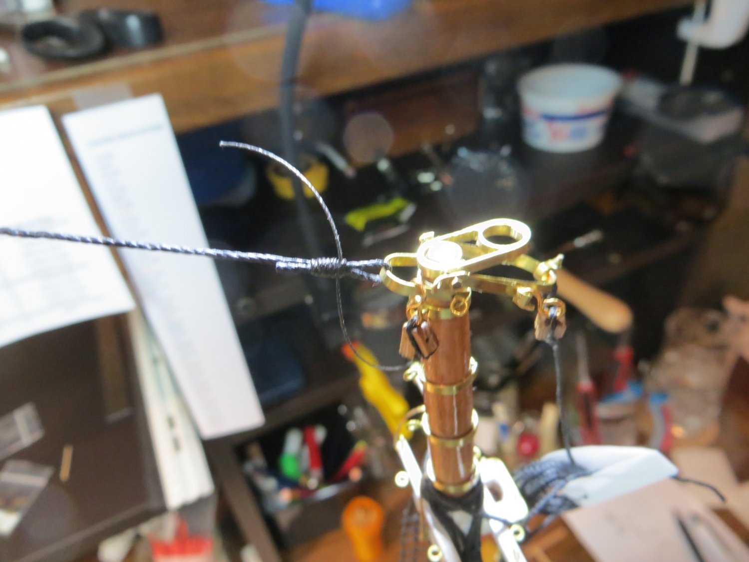
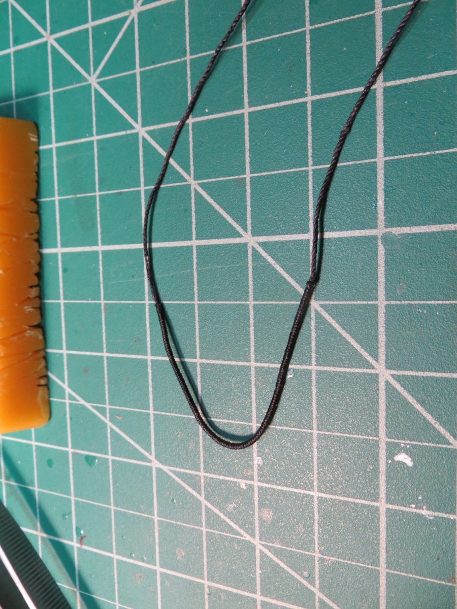
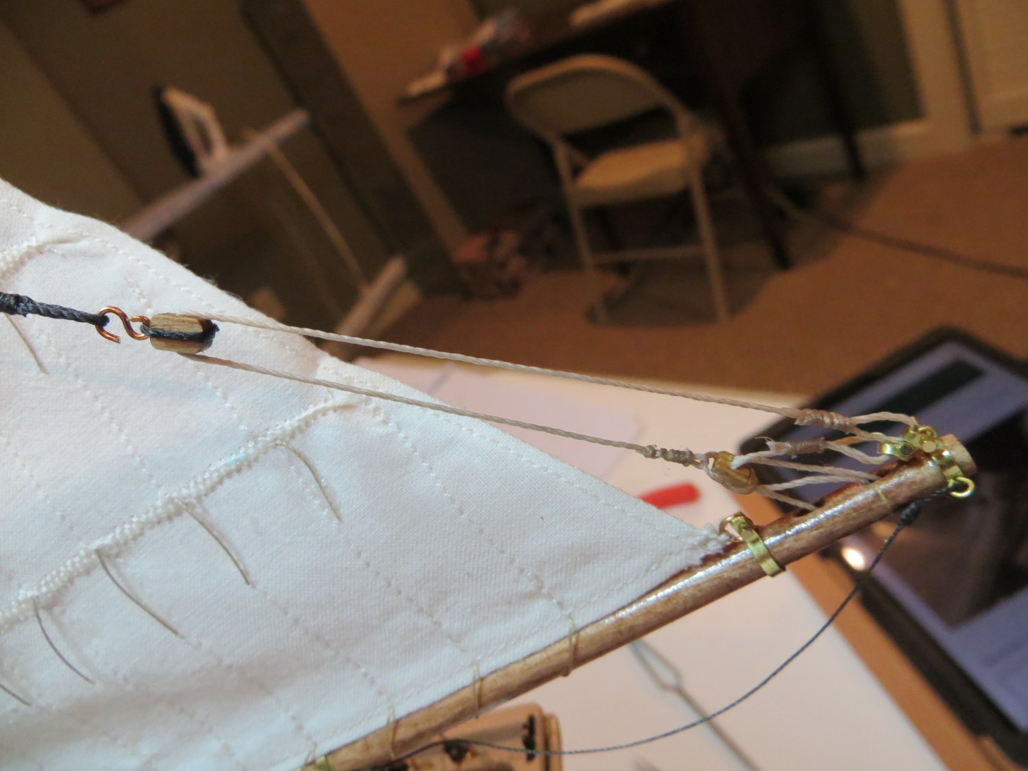
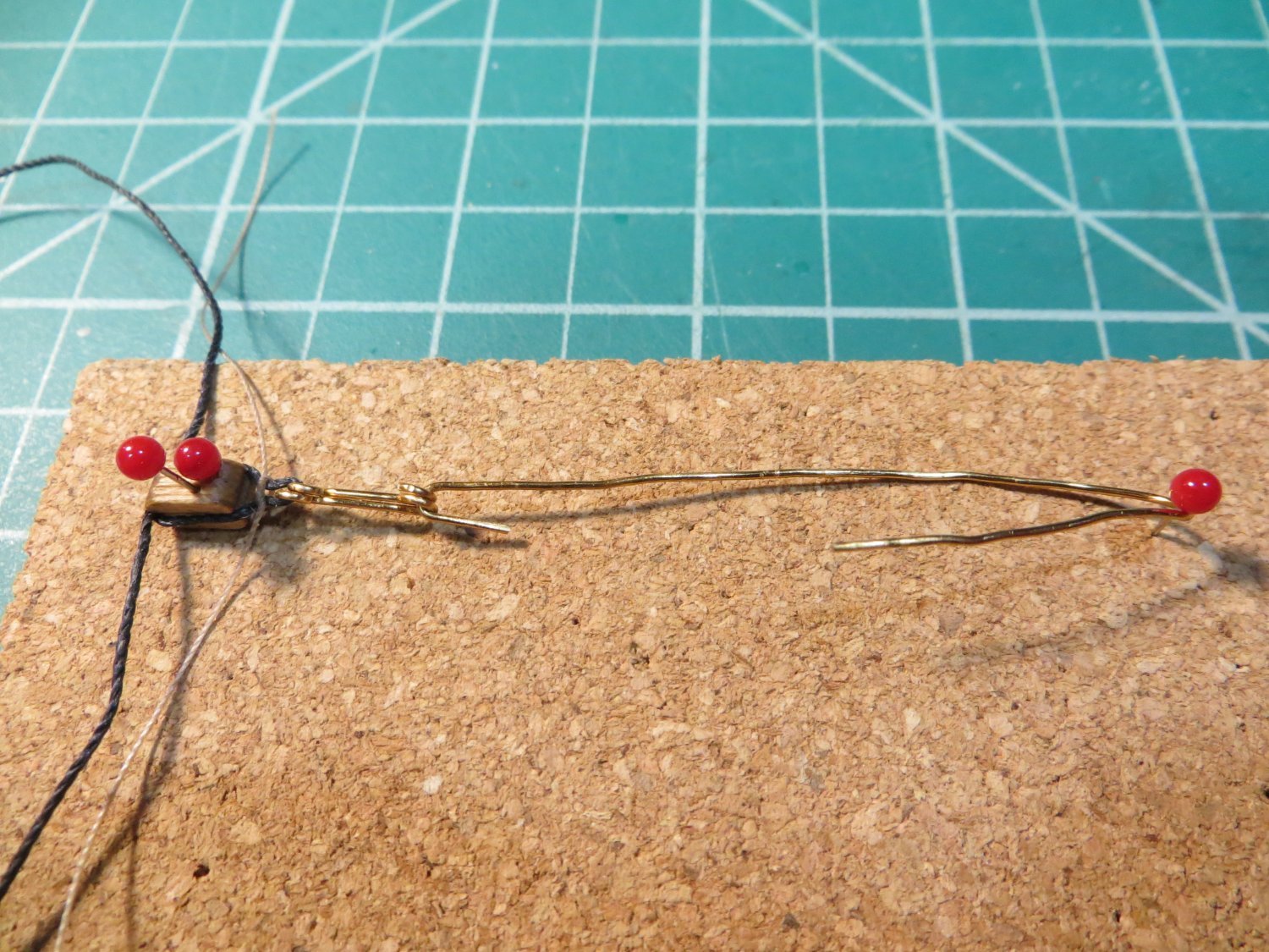
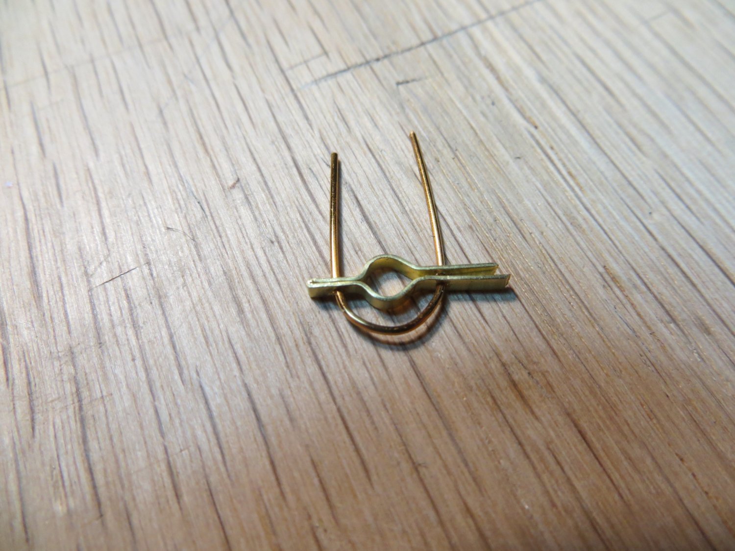
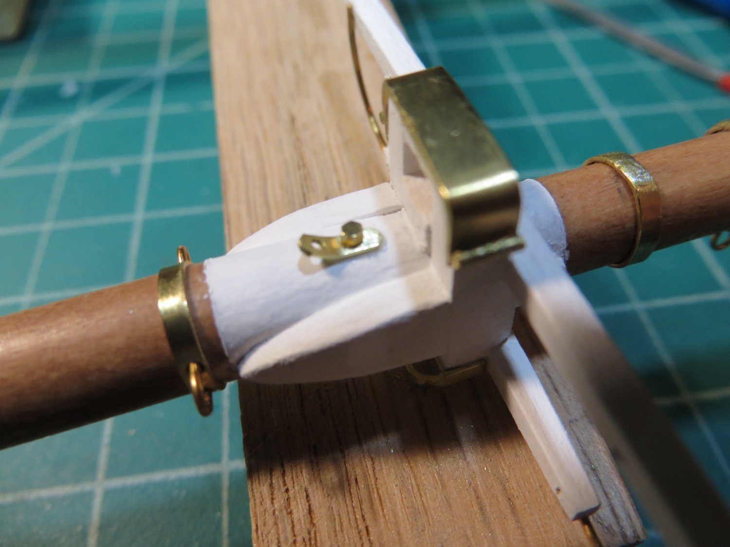
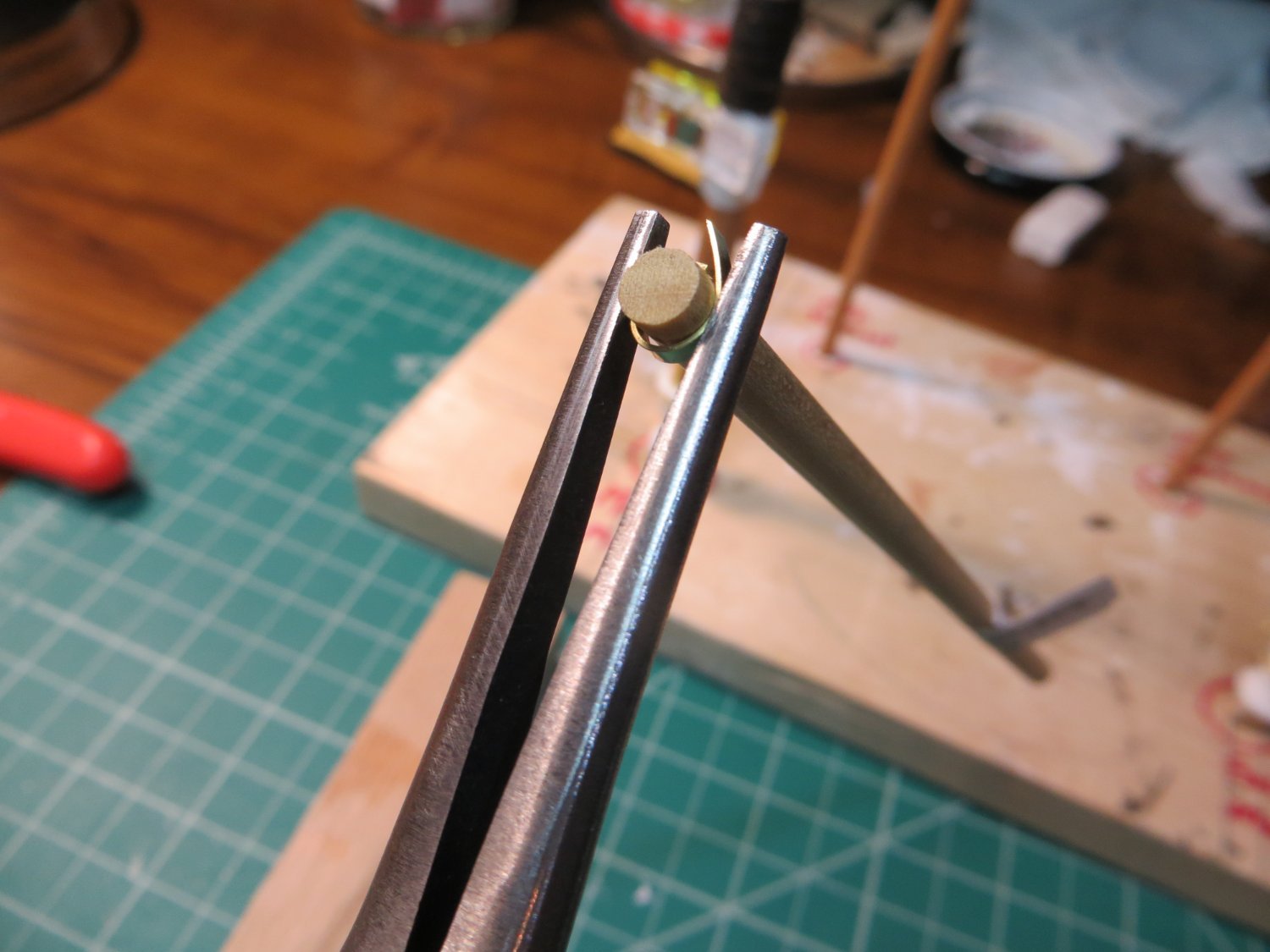
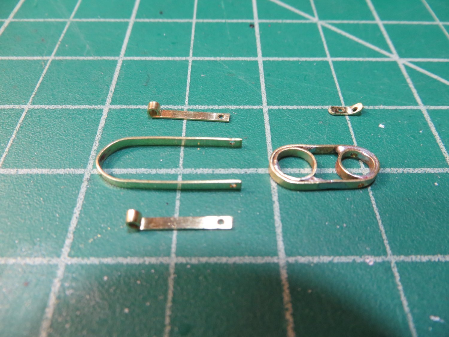
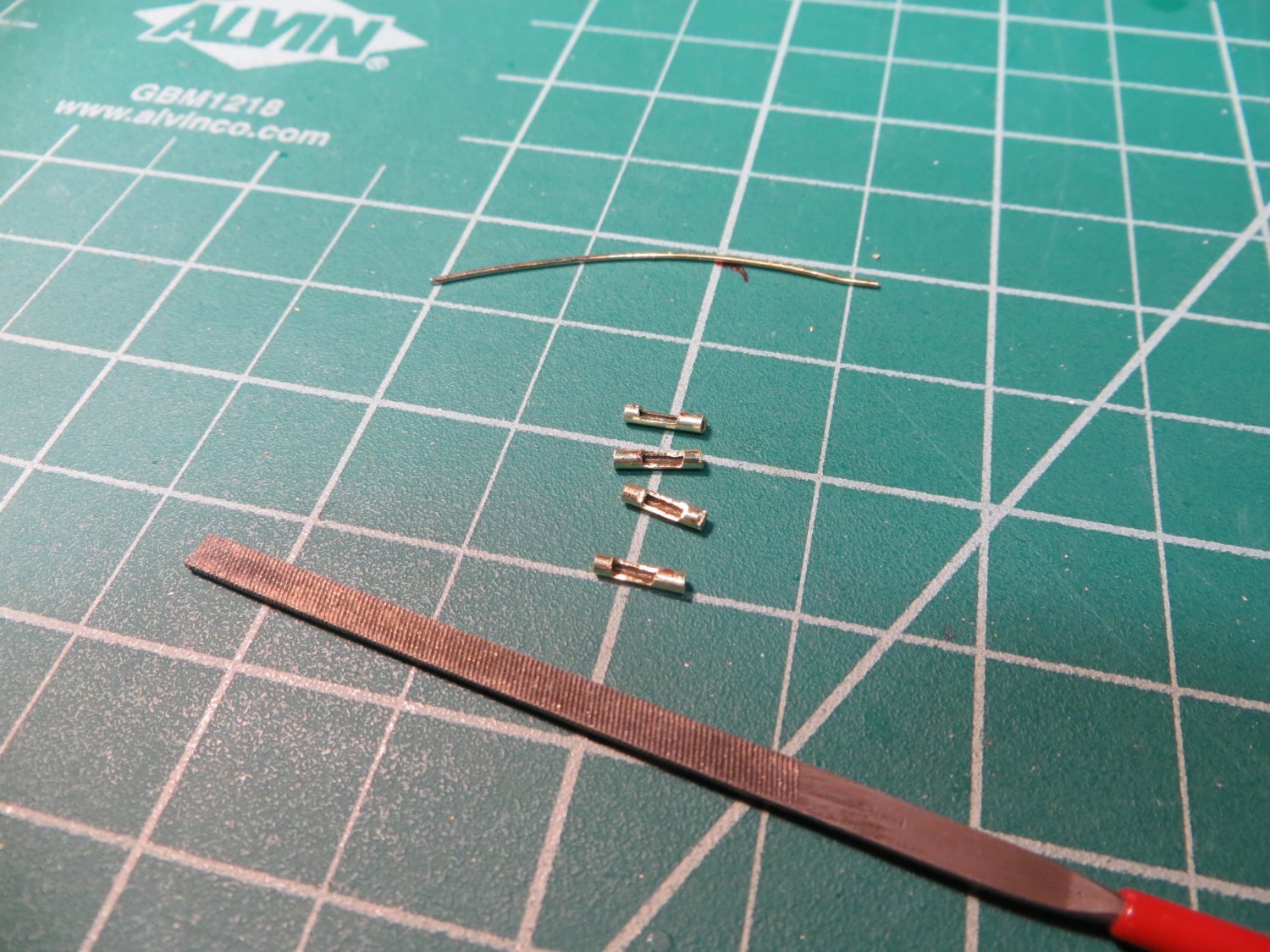
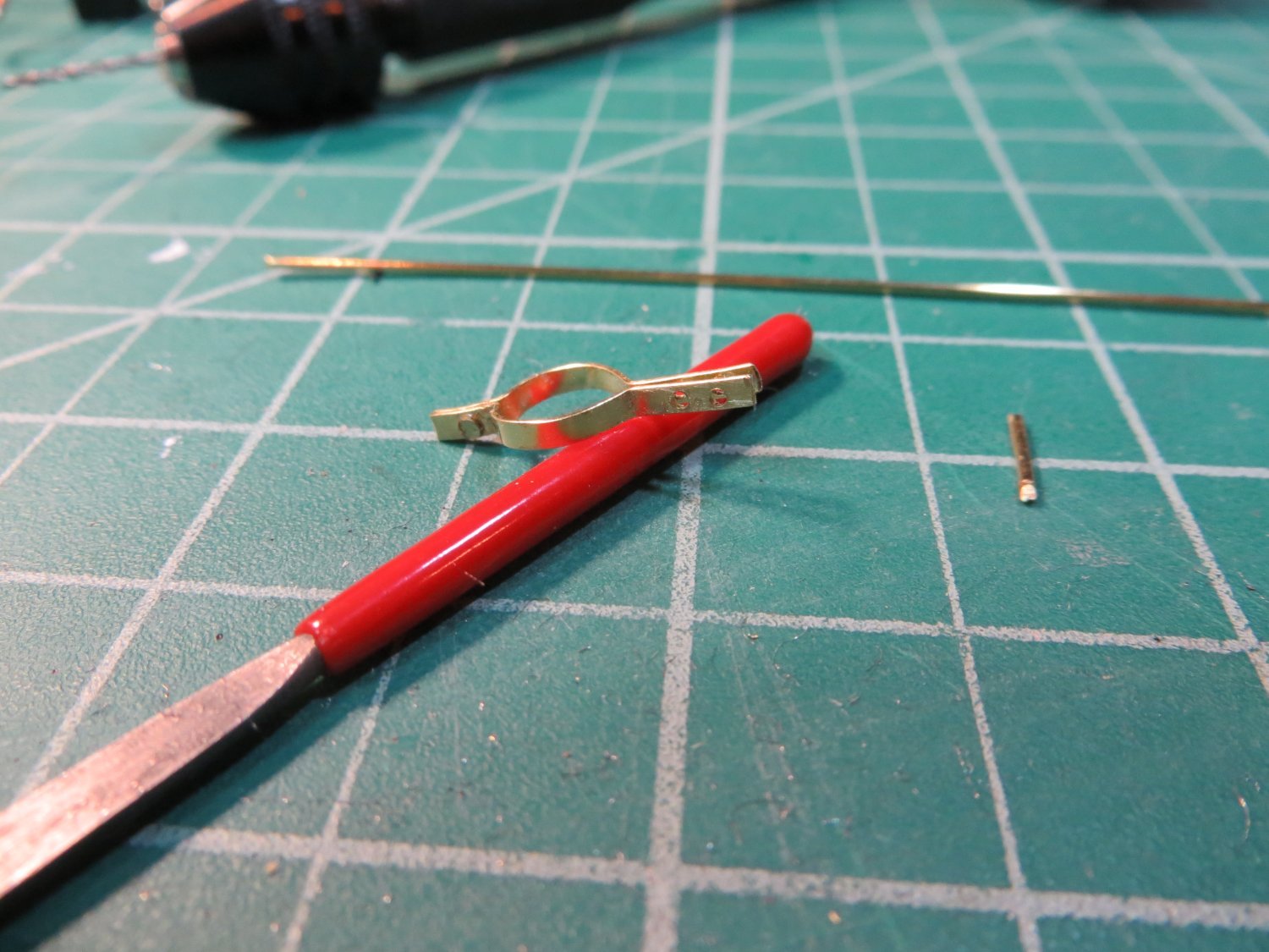
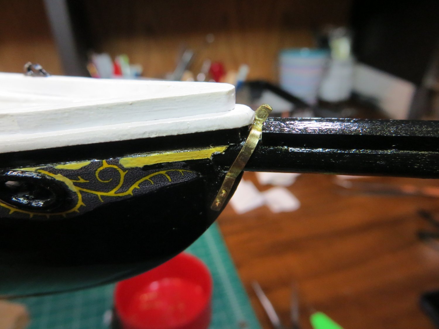
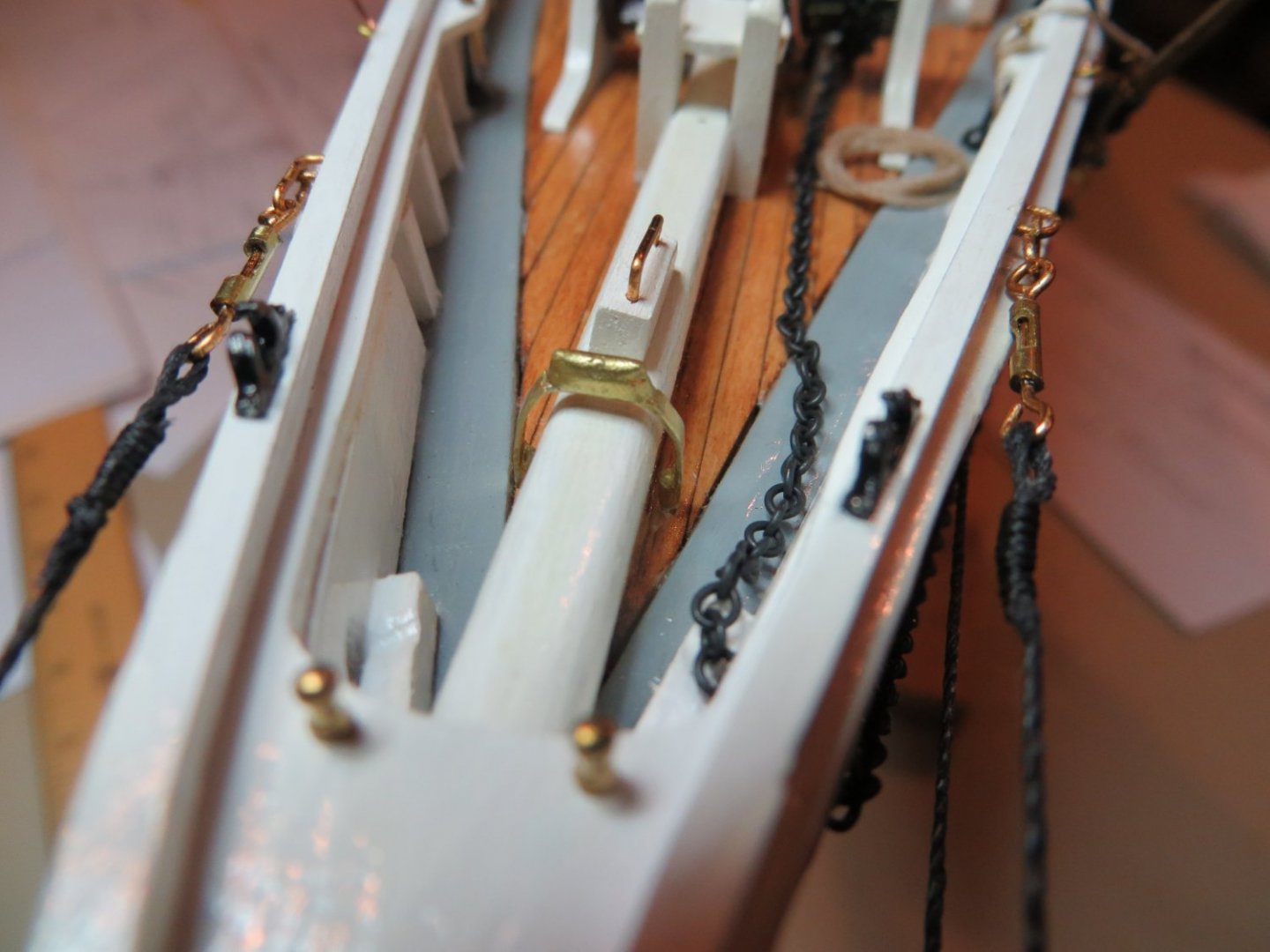
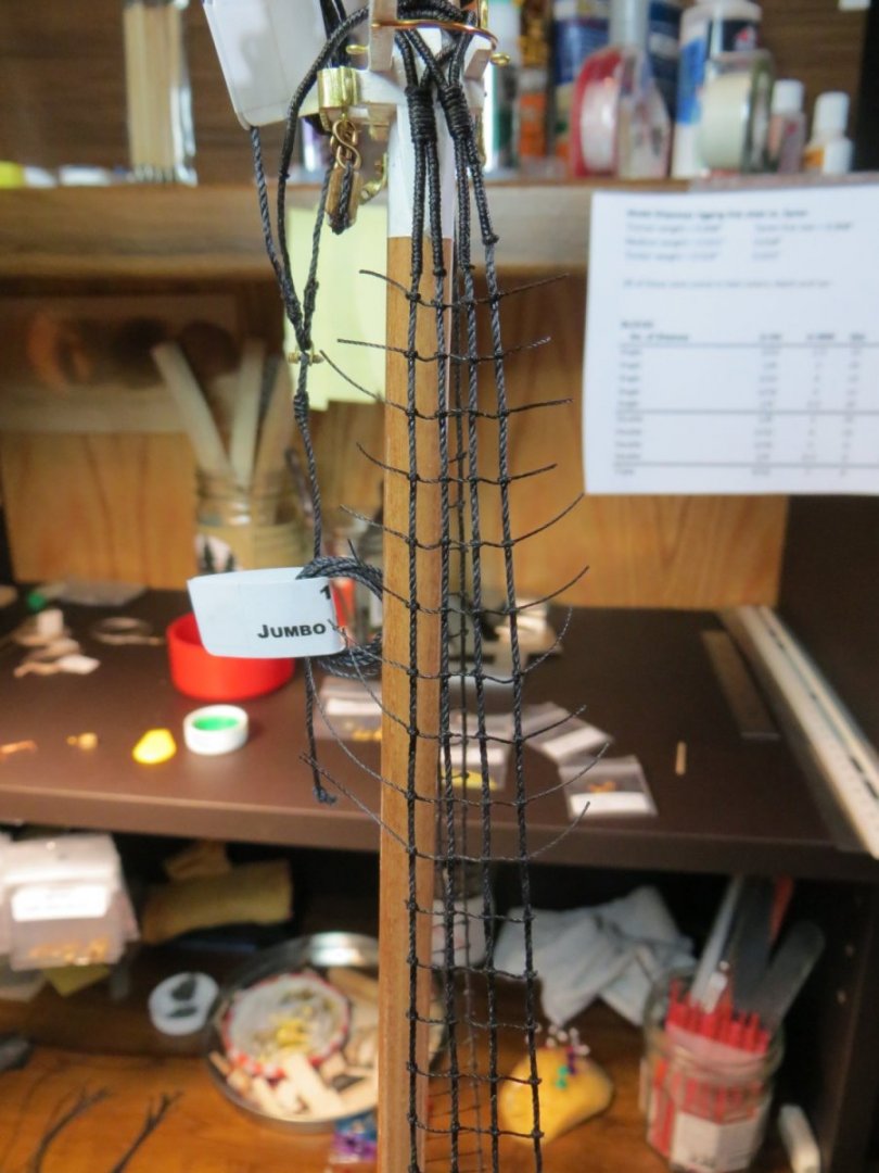
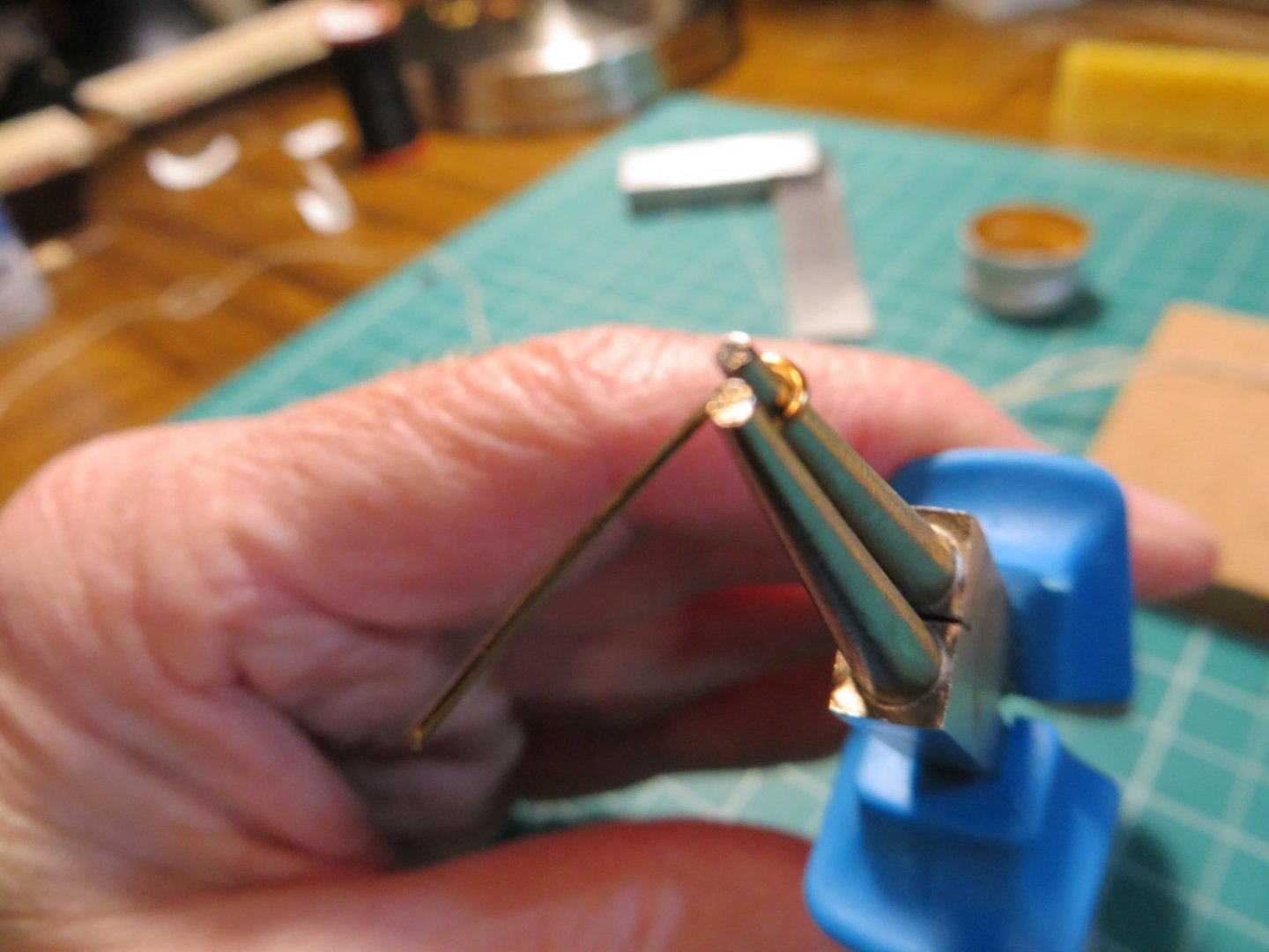
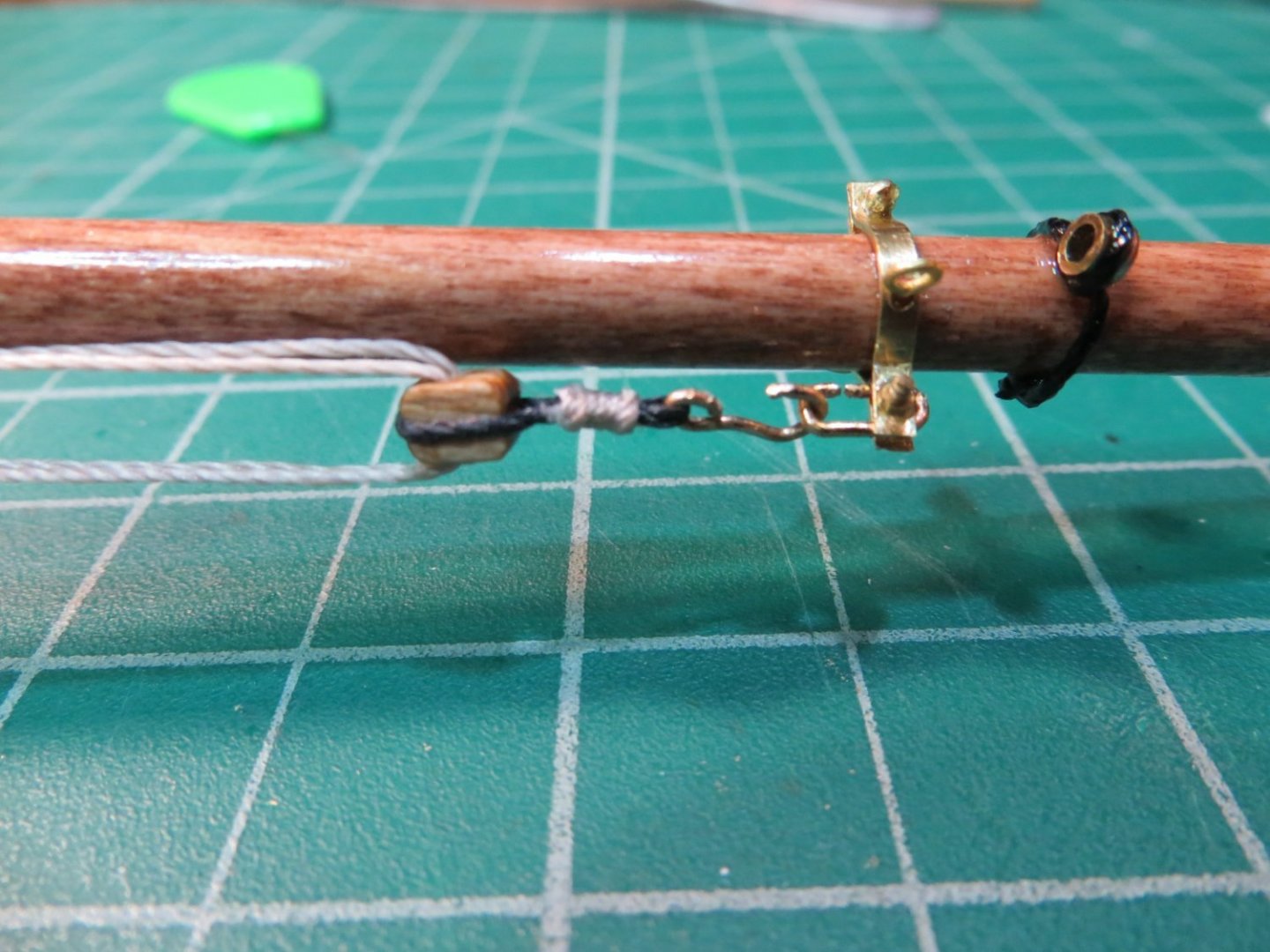
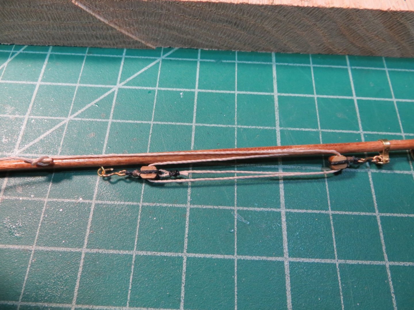
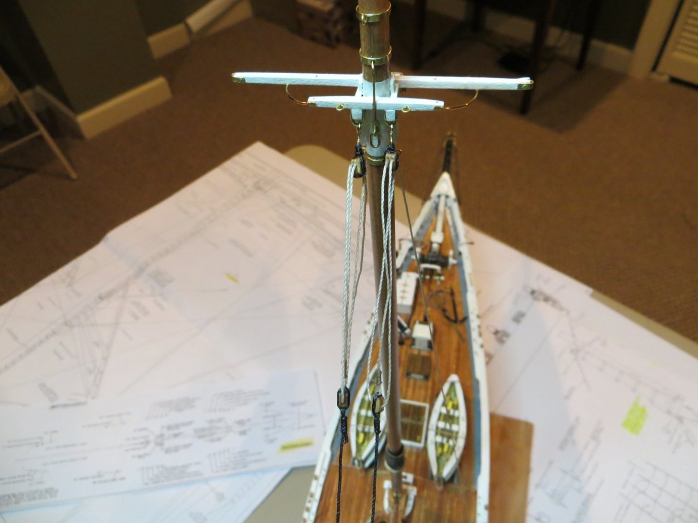
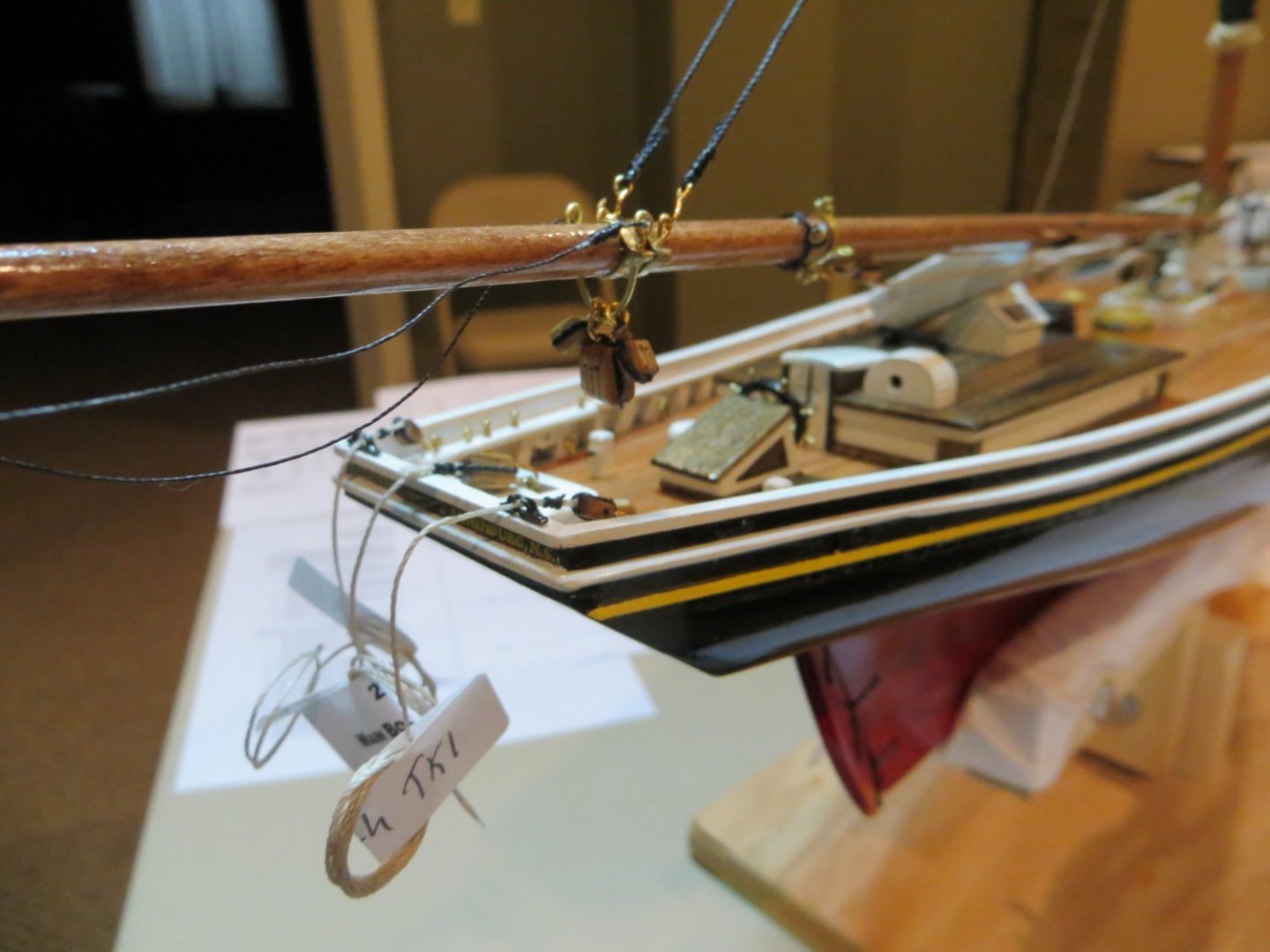
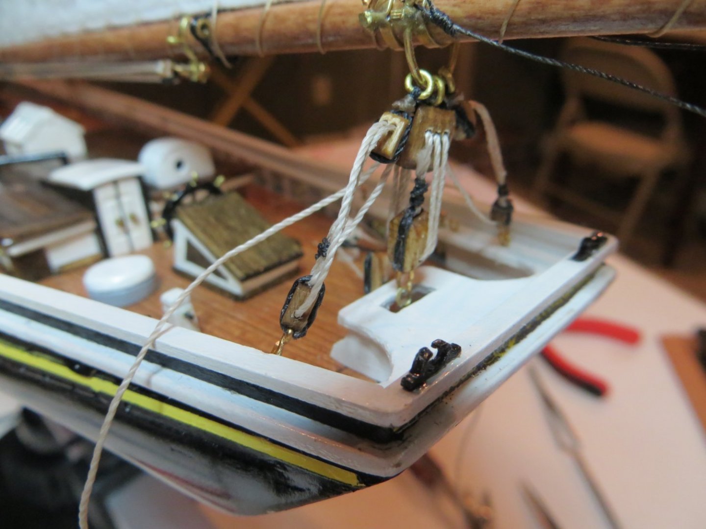
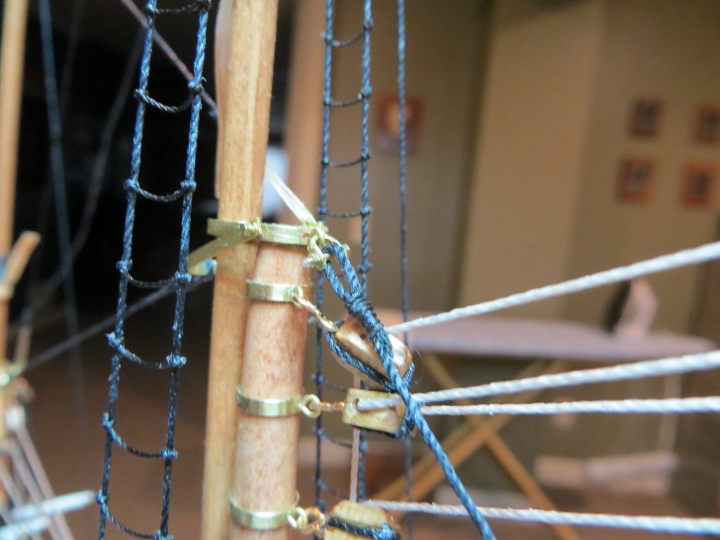
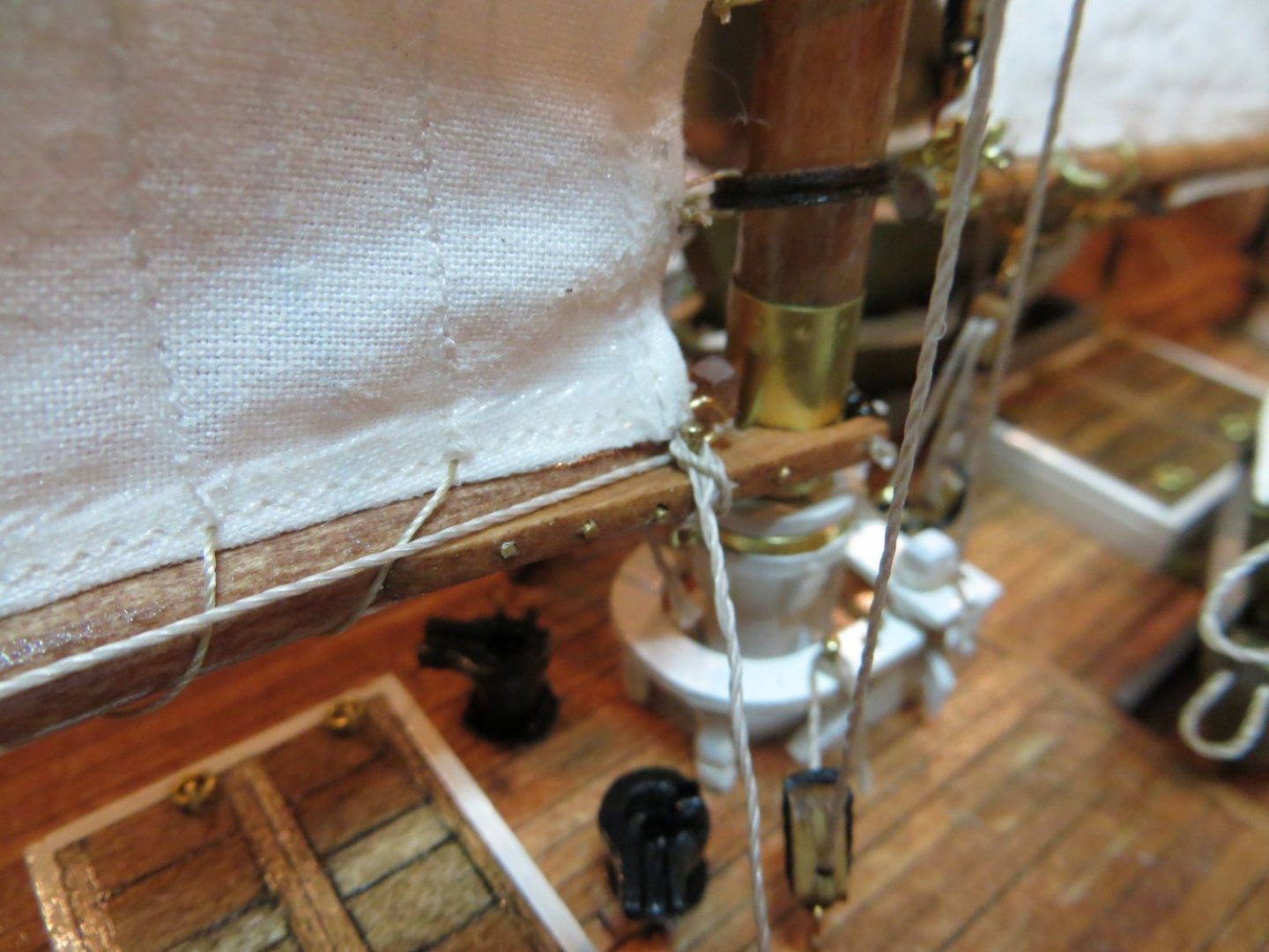
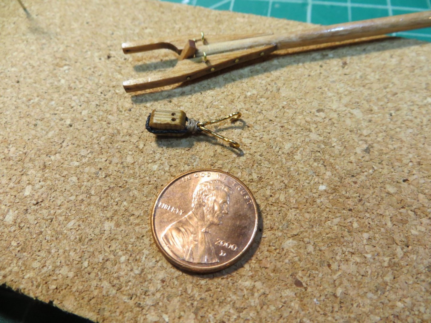
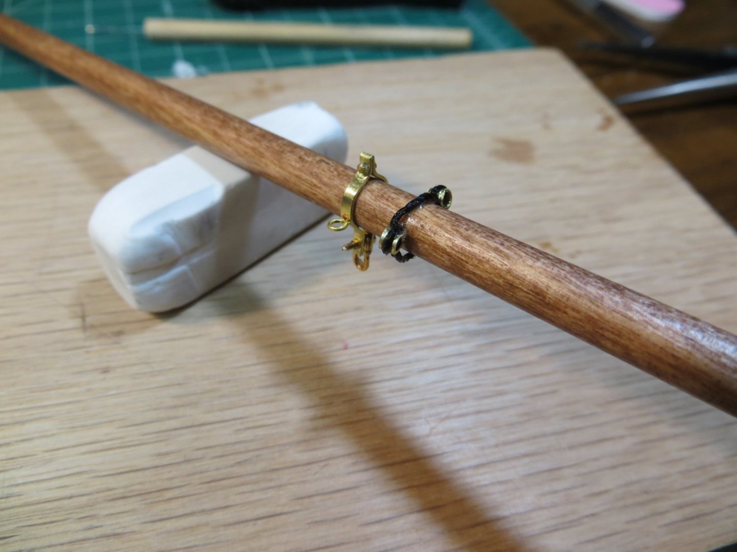
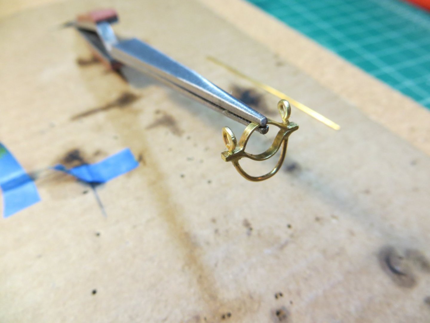
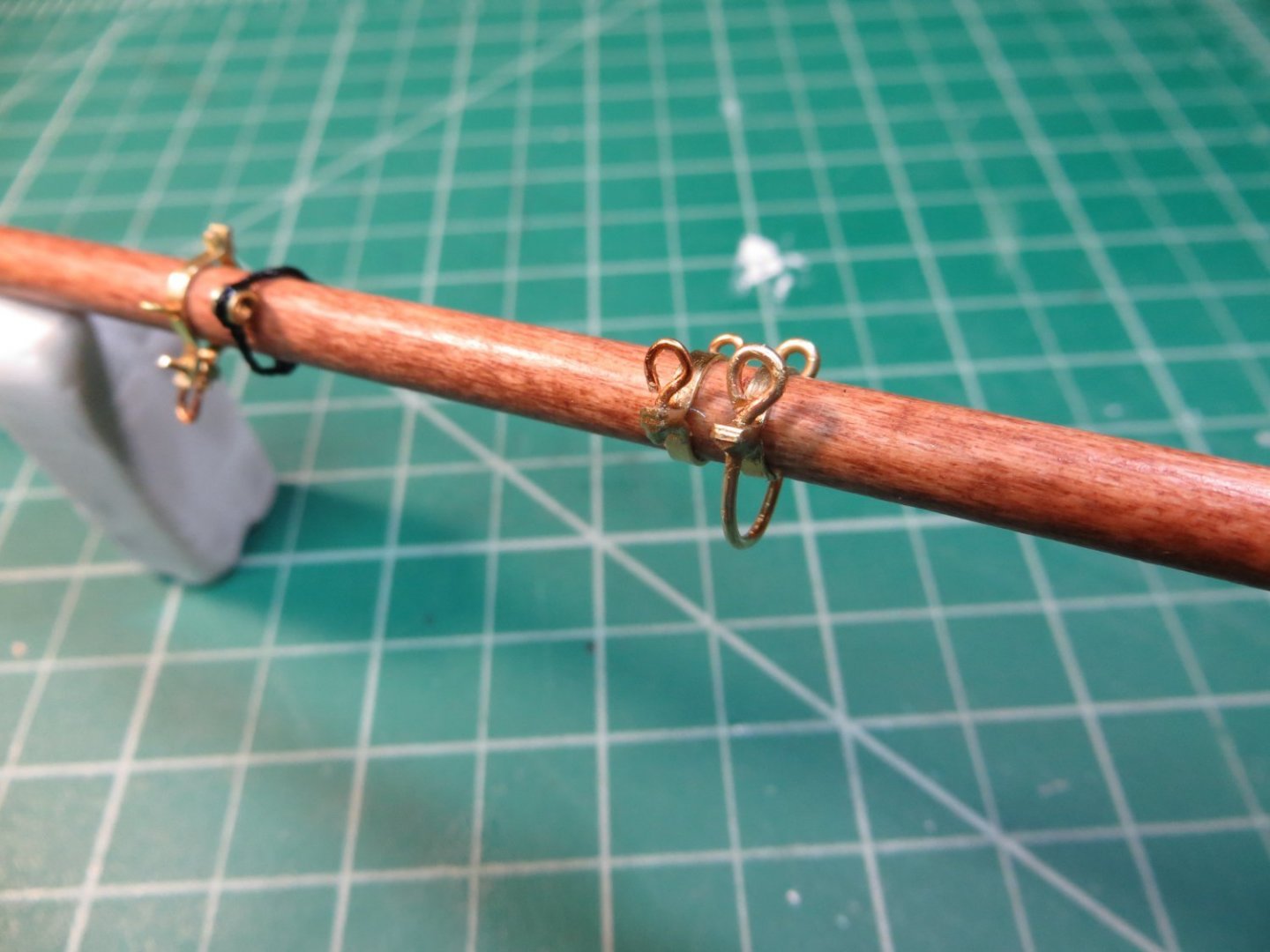
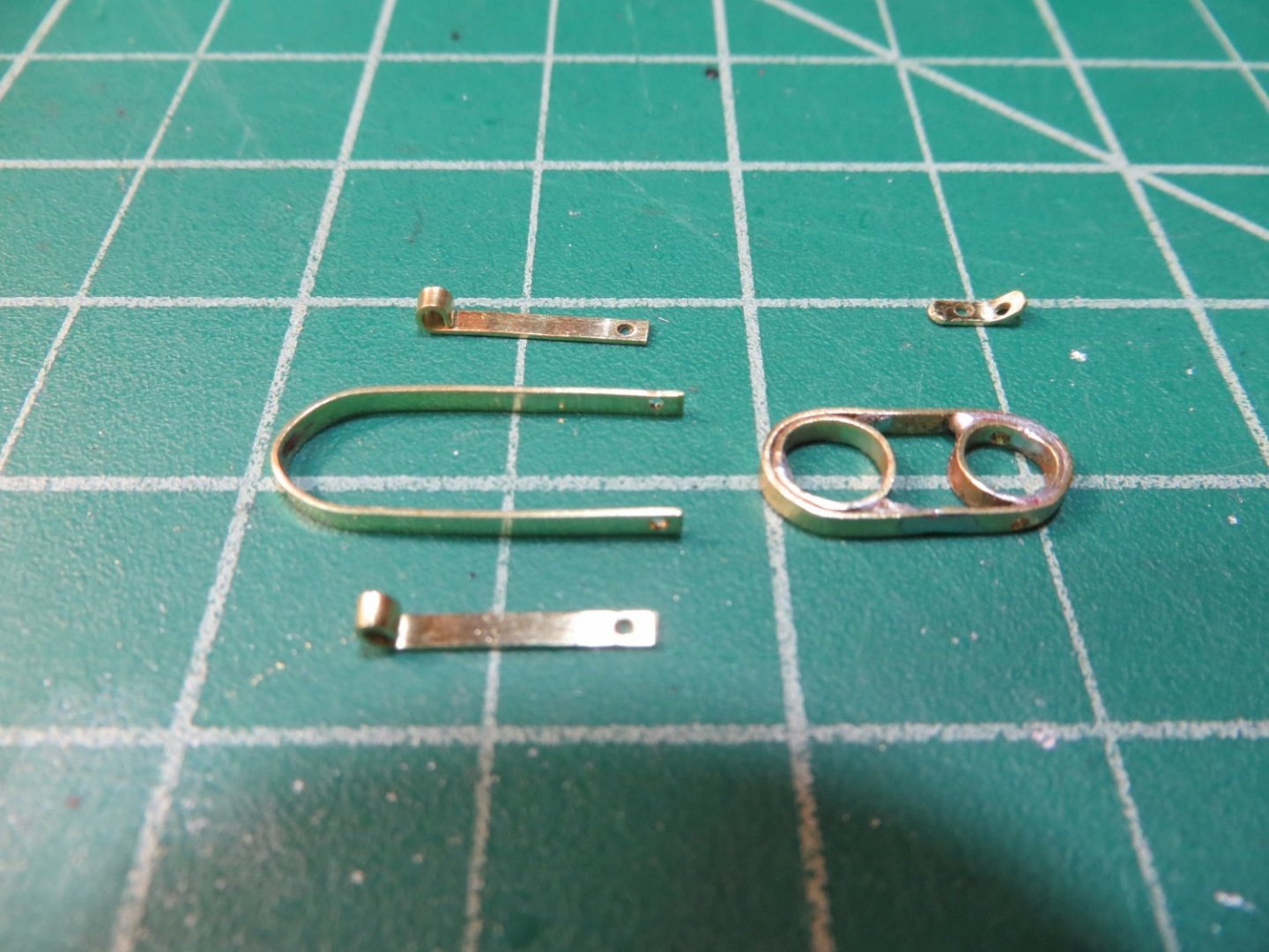
 Miscellaneous Pre-Rig Steps Before Lower Shrouds & Deadeyes are Installed High-Level Pre-Rigging Plan 3. Pre-rig the Spring Stay, Jib Stay and Jumbo Jib Stay on the lower mast caps 4. Pre-rig blocks, fairleads, eyebolts on lower masts, bowsprit & deck for sail halliards/downhauls. 5. GLUE the LOWER MASTS (Not the topmasts, to leave room to work on lower shrouds) Spring Stay – can be permanently attached at this time. Use 0.028 Black rope. Seize the fore end to the spring stay on the fore mast cap. Seize the aft end to the spring stay on the main mast cap. These must be seized in place. I cut the rope longer then needed and use some small plastic clips to hold the ropes together while wrapping the seizing. Sorry for the out-of-focus pic below. That top rope is the spring stay! Below: close-up of the foremast end of the spring stay in process of seizing. The other end was similar. Notice the miscellaneous blocks I attached here and elsewhere around the ship as part of pre-rigging. Jumbo Jib Stay – cannot be permanently attached until the Jumbo Jib Sail is attached. The stay must be slipped through the “Hanks” (brass wire split rings) on the edge of the sail, when it is time to be rigged. However, we can pre-rig this stay to the top of the lower mast head. Here are the steps I used: 1. There are 2 ropes for the jumbo jib stay. Start with the upper rope, which is called the “Bridle”. Use 0.028” black line. Cut a sufficient amount based on the plans and some rough measurements. 2. The bridle wraps around the fore mast just above the trestle tree. Only about 1 inch of rope is required between the trestle tree and the end of the bridle. It rests on either side of the iron gate on the front of the trestle tree. The top of the rope that wraps around the mast must be served. 3. The two rope ends are connected with eye splices to a shackle. I made up a shackle using my usual procedure (see post # 27 in this topic) Below: My hand crafted shackle and the mini-bolt and nut used to close the open end 4. The lower end requires us to make a custom piece of hardware called the Jumbo Jib Stay Bail. This is a brass saddle that straddles the bowsprit and is anchored to the deck. According to the plans, it is attached to the deck using 2 shackles. I did not see how I could make this very well, so I made mine a little different. a. I cut a piece of the kit supplied brass strip and bent it in a U shape so it fit around the bowsprit while sitting on the deck. b. I soldered a short piece of brass tubing on top. I filled the gaps between the tube and the strip with solder to simulate the shape shown in the plans. See pic below c. I replaced the shackles on the bottom ends with 2 pieces of 0.032” brass rod. I soldered these so they formed pins that could be inserted into the deck to hold the bail in place. d. I used some brass enamel paint on the finished bail to cover the solder. e. I used the pin vise to make holes on either side of the bowsprit and glued the bail down Below: completed Jumbo Jib Stay Bail 5. I made an eye splice on one end of a 0.028” length of black line for lower rope #2. This was inserted into the shackle at the end of the bridle. The entire rig was coiled up and labelled for later. Jib Stay – this too cannot be permanently attached until the Jib Sail is attached to it. This one is pretty simple. The upper end of the stay is seized to a shackle. The shackle connects the stay to the jib stay bail at the top of the fore mast. Later it will be seized to another shackle on a ring near the end of the bowsprit. For now, it is coiled up and labelled for later. Lower Masts – glued in place. Theoretically, the masts do not need to be glued at all. The rigging should hold them in place. But this being my first model ship, I decided to make sure they were well secured and unable to move around while I’m doing the sails and rigging.


- 96 replies
-
- 4
-

-
- model shipways
- bluenose
- (and 1 more)
-
Jonathan, thanks for your encouragement to keep doing my documentation. At one time in my former career, I developed technical training materials and was a corporate trainer. So, I actually do enjoy doing this stuff!
-
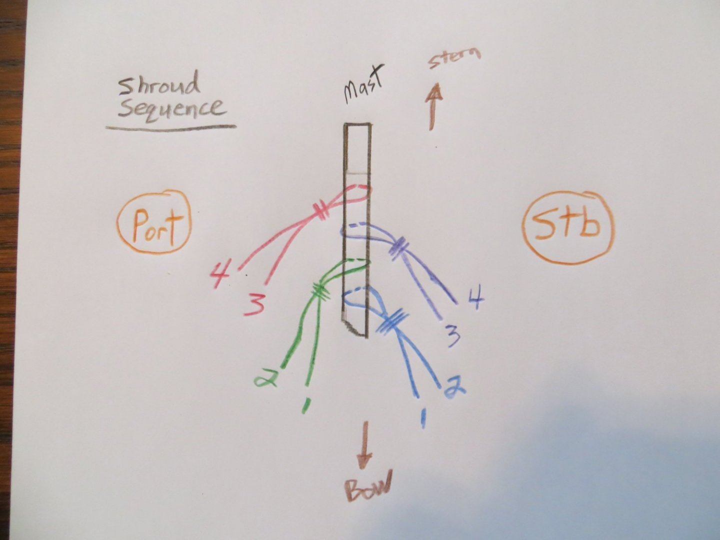
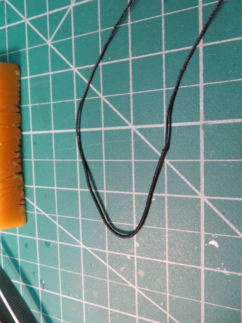
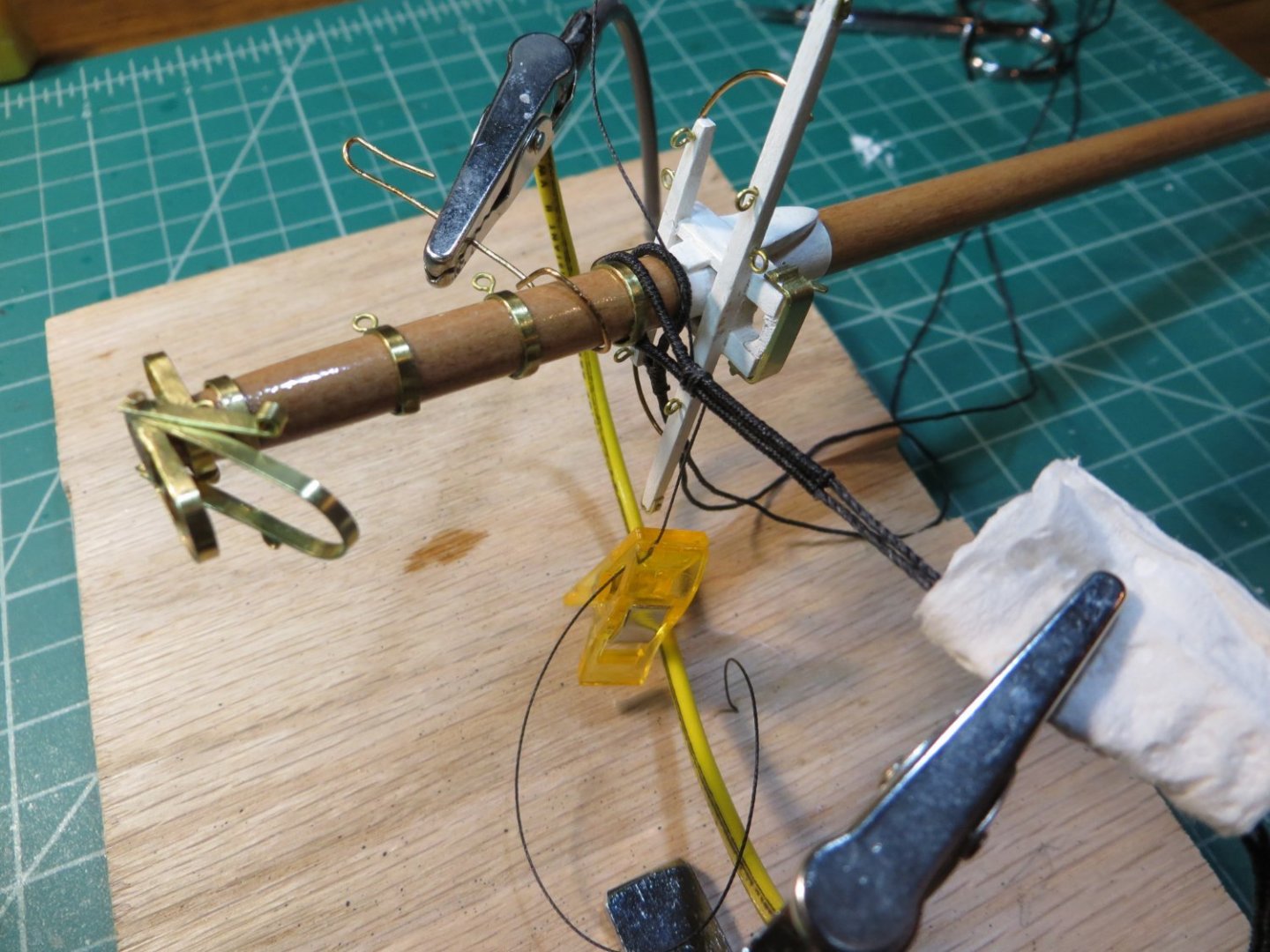
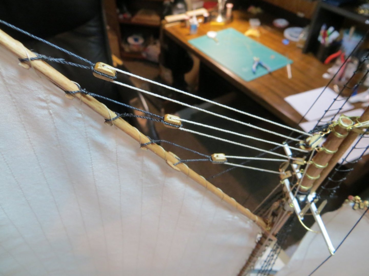
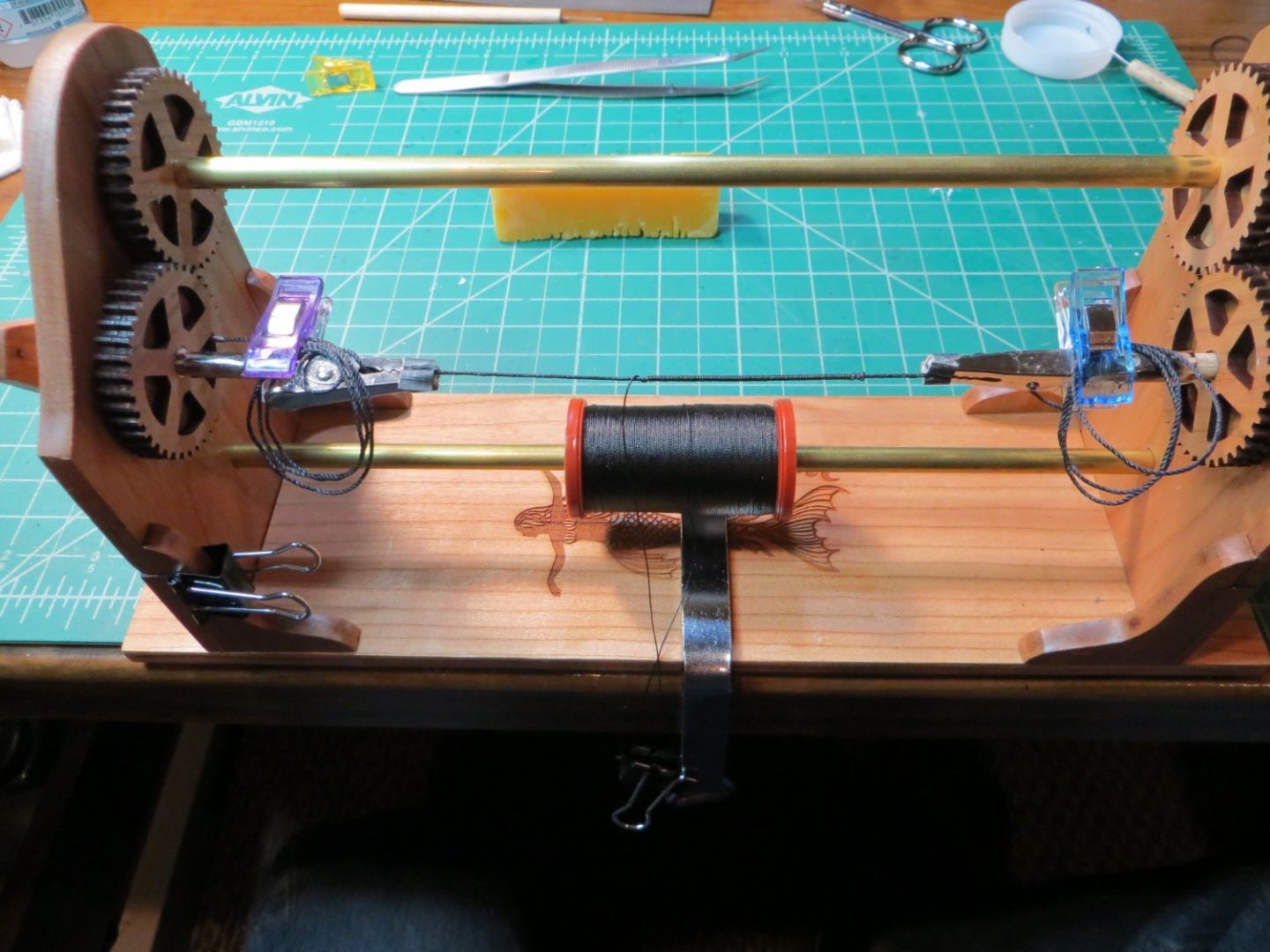
Pre-rigging the Lower Mast Shrouds: In the last two posts I covered "High-Level Pre-rigging" Step #2: Booms & Gaffs. On to Step, #3: Pre-rig both the fore & main lower mast shrouds. FYI, here is a partial re-print from my plan that I covered in Post #46. My High-Level Plan for doing Pre-Rigging 1. Work from the Deck upward (booms then gaffs). And inside-out from masts to railings 2. Pre-rig the running rigging (sheets, tackles, lifts) on the Main Boom, Fore Boom, Jumbo Jib boom, Main & Fore Gaffs. Temporarily rig the boom or gaff to the mast, one at a time. Make the rigging lines for each spar and on the deck. Remove the boom/gaff, coil up and label each rig. 3. Pre-rig the lower mast shrouds at the top. Coil them up for later. 4. Pre-rig the Spring Stay, Jib Stay and Jumbo Jib Stay on the lower mast caps. Coil for later. And continuing… The shrouds hold the masts up from the port & starboard sides of the ship. Some of the heaviest ropes are used for this on the ship. The ropes are “served” where they wrap around the top of the lower mast head. Serving minimizes the wear & tear on the shrouds from rubbing against the masts. Serving is basically wrapping a smaller rope around a larger rope to create a sleeve around it. I bought the Syren Serve-O-Matic to make this job easier. You don’t need this tool to wrap thread around the shroud, but it makes it go a lot faster and produces a nice tight & clean appearance. Here are the steps I used to pre-rig the Shrouds: 1. Measure the amount of 0.028 black rope required, add some extra for seizing around the deadeyes later, and then cut. As always, apply beeswax. 2. Find the middle of the line, measure how far the serving is required and tag it there (I tie a small piece of thread on either side of the middle) 3. Use the Serve-O-Matic to serve the rope in the measured area 4. Wrap the rope around the lower mast above the Trestle Tree 5. Remove the mast from the ship and secure it in the rigging jig. Seize the 2 ropes together. The lines then run down between the spreaders 6. Coil the pair of lines up for use later LOWER SHROUD SEQUENCE: First wrap lines 1 and 2 around the mast, seize them together. I started with the starboard side. Then do the same with 1 and 2 on the port side. Shroud 1 should always be the first one facing the bow. Alternate sides. Repeat the same sequence for 3 and 4. Shroud 4 should be the last line facing the stern on both sides. Below is my sketch showing the sequencing of the shrouds: 1 & 2 are the same line wrapped around the mast and then seized to make two shrouds. 3 & 4 are similar. I installed 1 & 2 on the starboard side first. Then alternate them as shown below. Serving the rope on the Serve-O-Matic. The excess line is coiled up on either side. There is a handle on the right side for turning the rope while you hold the thread with your left hand. Below: The completed shroud after serving Below is the fore mast held in my rigging jig with some wire while I seize the two lines. When done the lines are threaded into the space between the spreaders and the brass rod. Alternate sides with each pair of shrouds. The below pic was taken later when I was installing the ratlines. But this is a good view of the 4 shrouds sitting in their position in the trestle tree. If I were to do it over, I would have stopped the serving rope a little shorter then I did so there was more space for another ratline or two.

- 96 replies
-
- 1
-
-
- model shipways
- bluenose
- (and 1 more)
-
I need some help from someone who has completed the sails on Bluenose I. I cannot find any details on how to attach the lower forward corner of the Jib sail to ring 2 on the bowsprit. I know hanks hold it to the jib stay and there is a downhaul running through a block nearby. Should I use a corner ring on the sail and slip it into the shackle that holds the jib stay??? Appreciate any expert advice! Thanks!
-
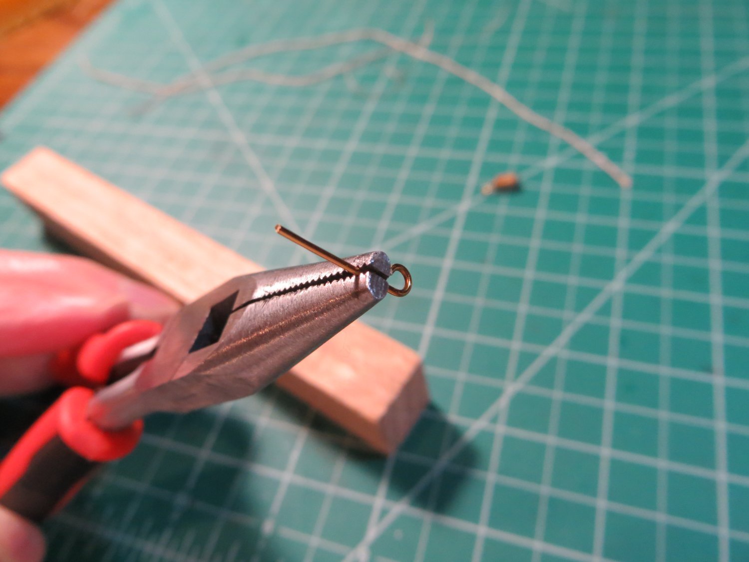
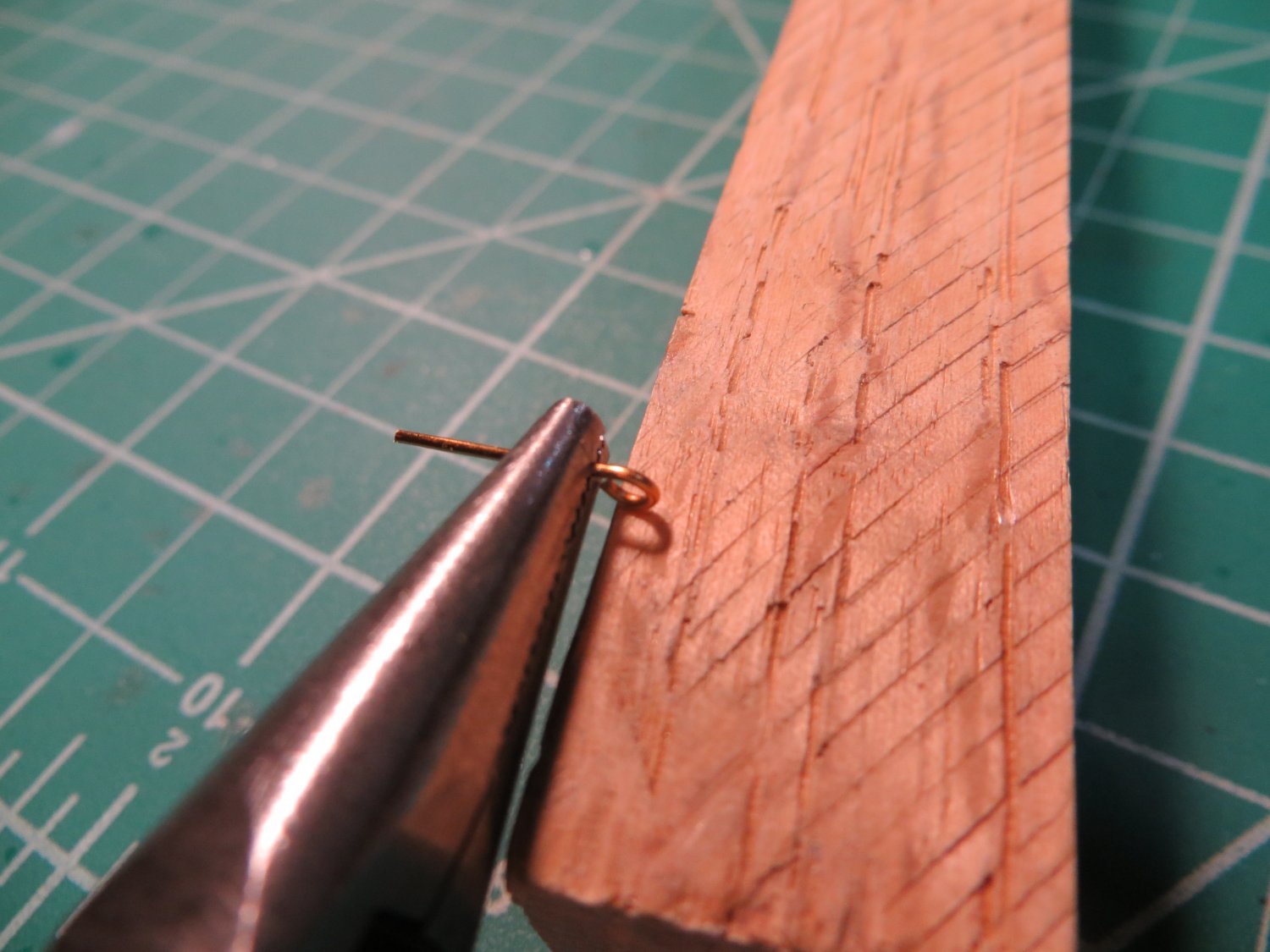
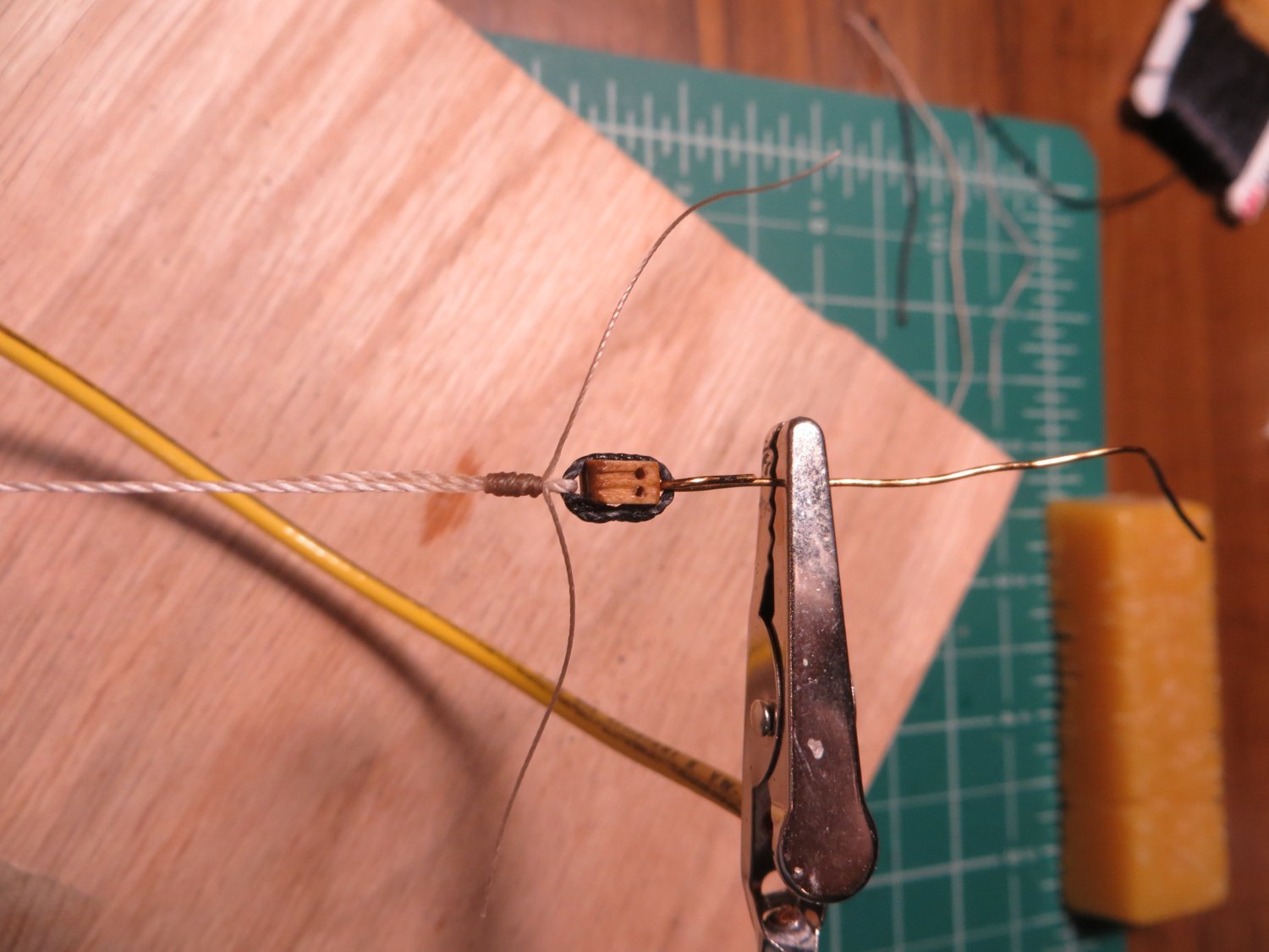
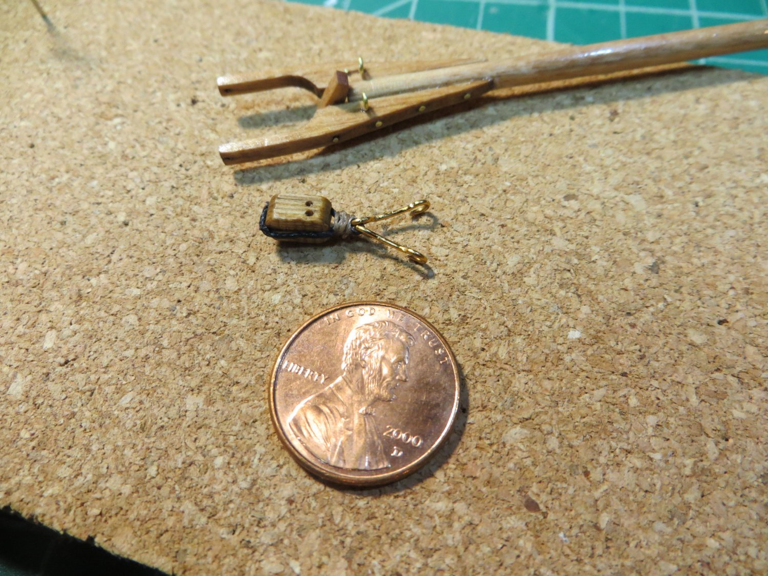
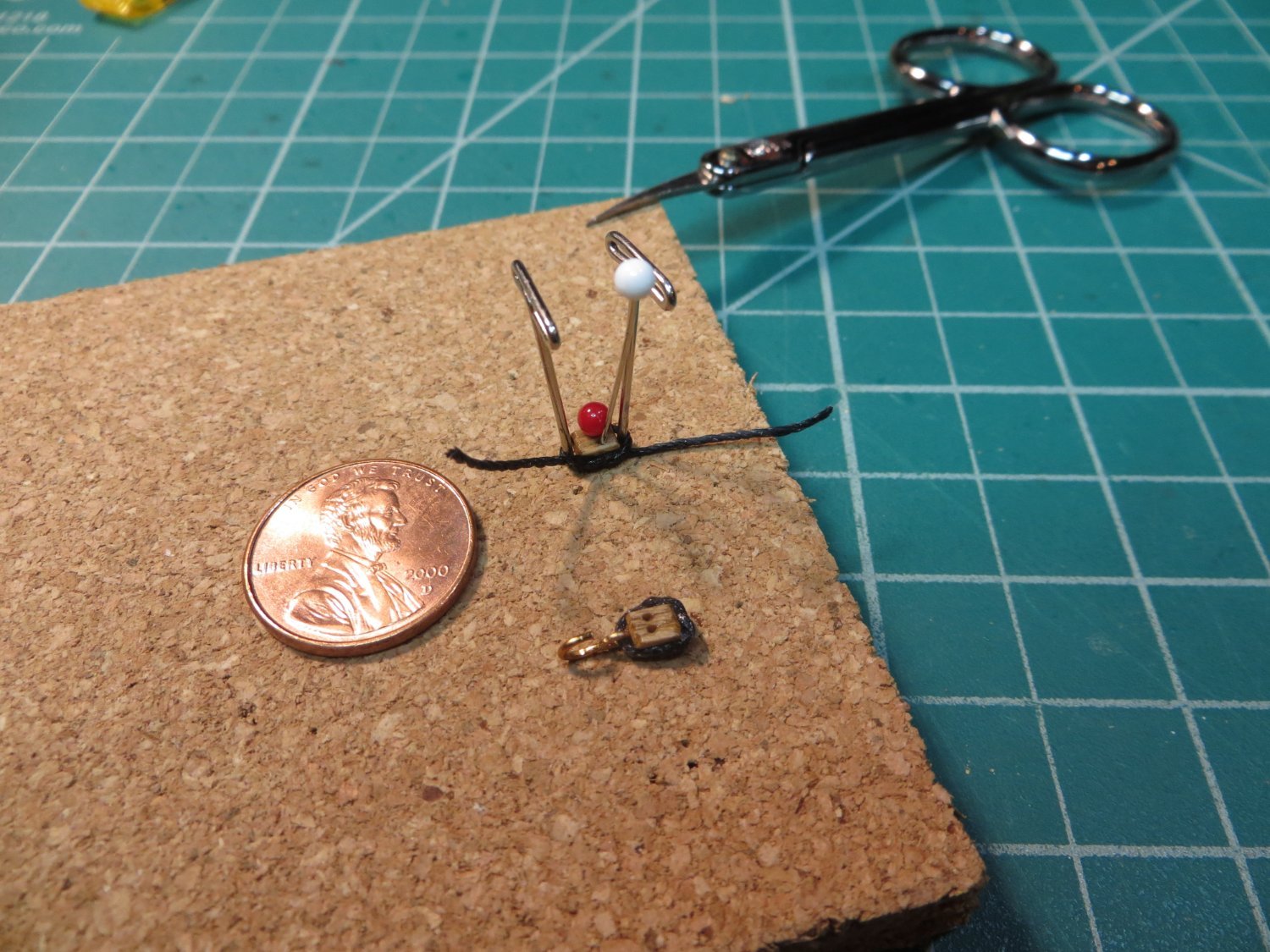
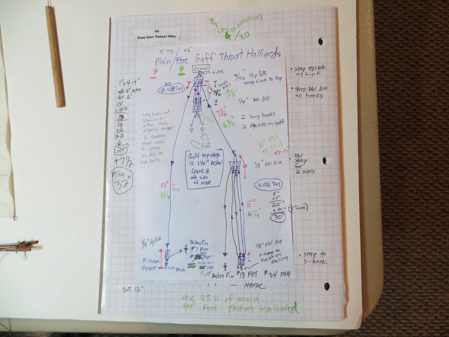
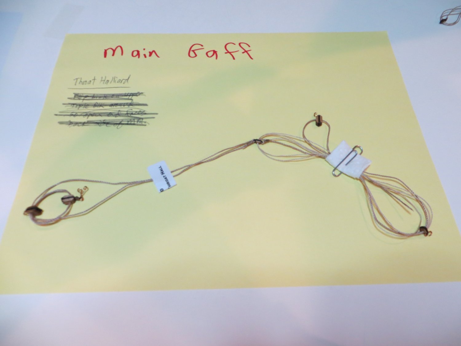
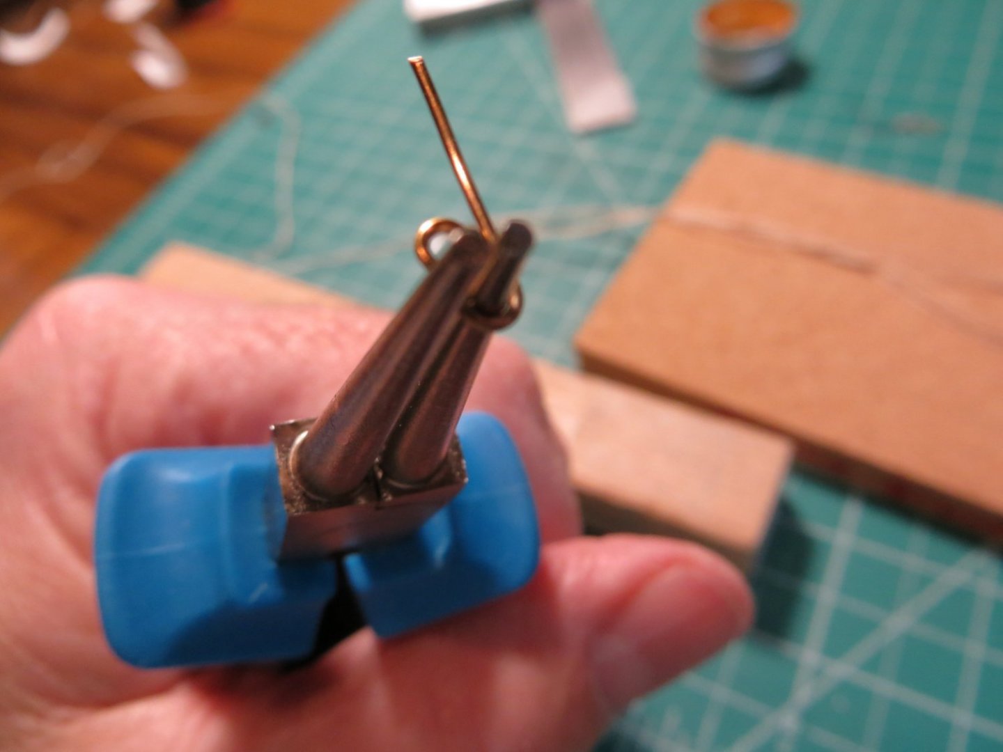
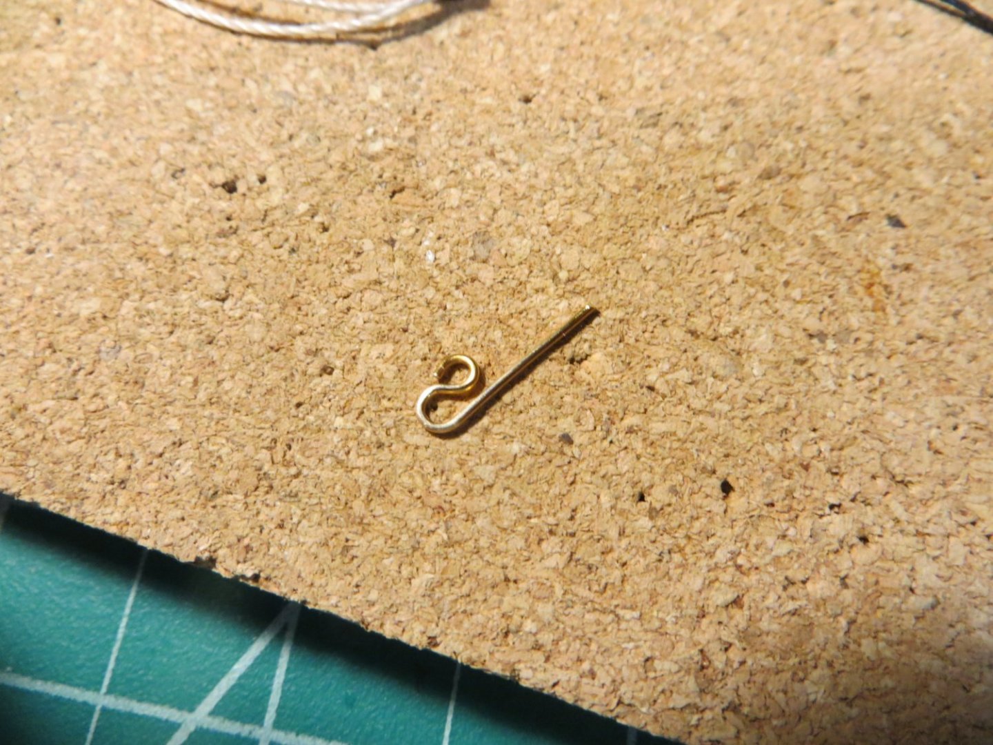
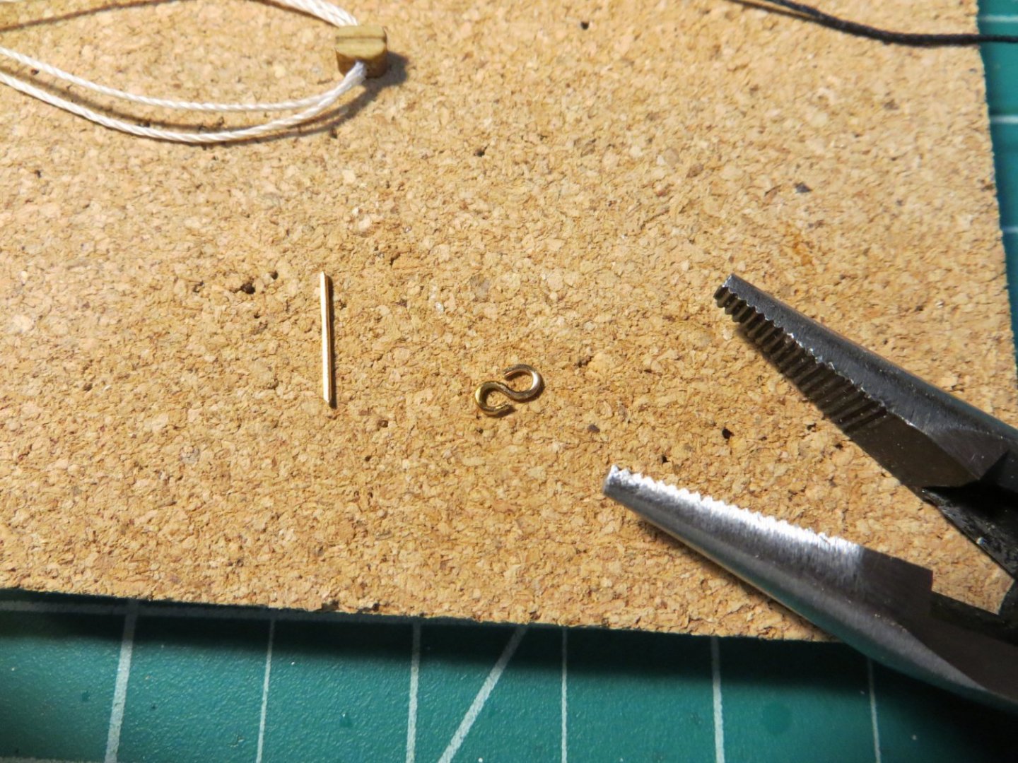
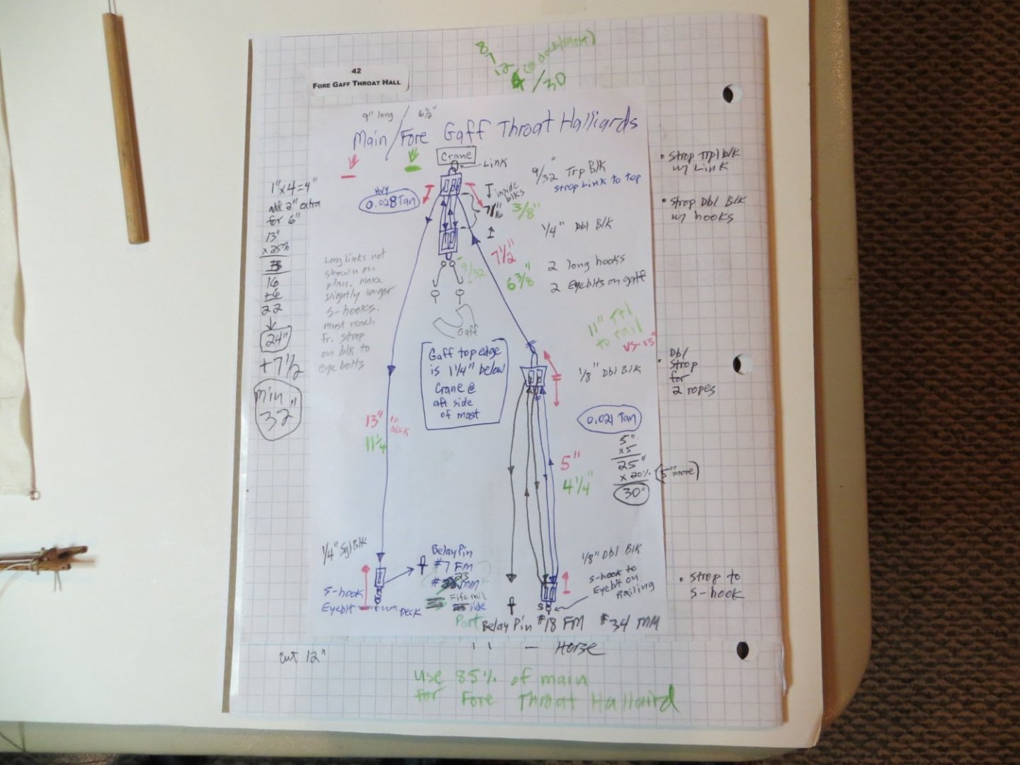
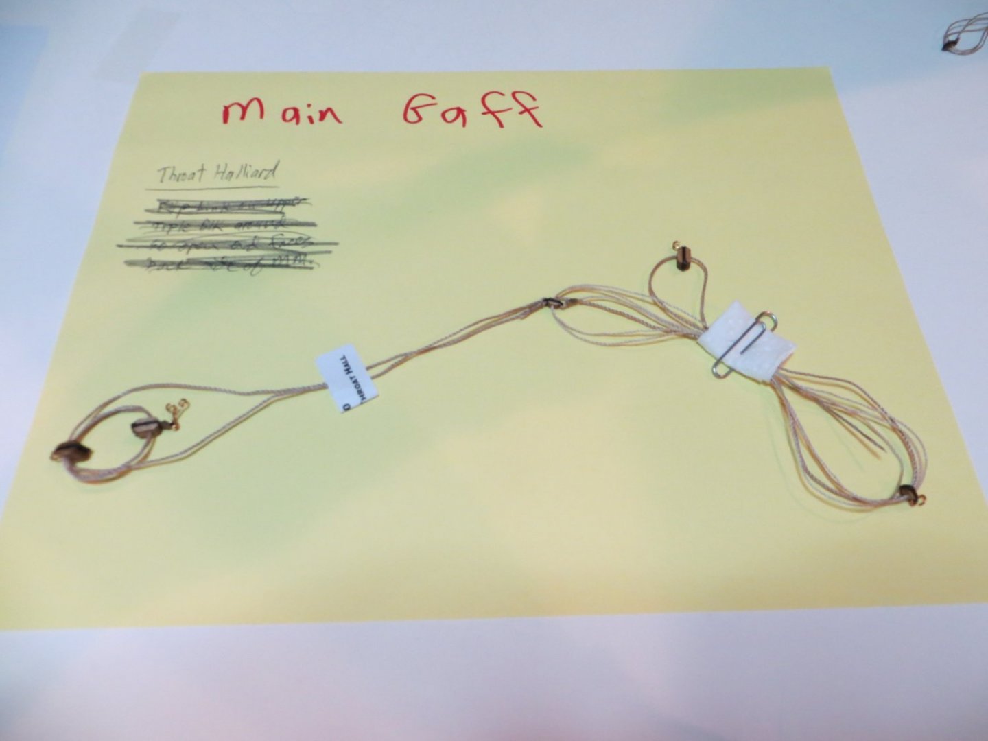
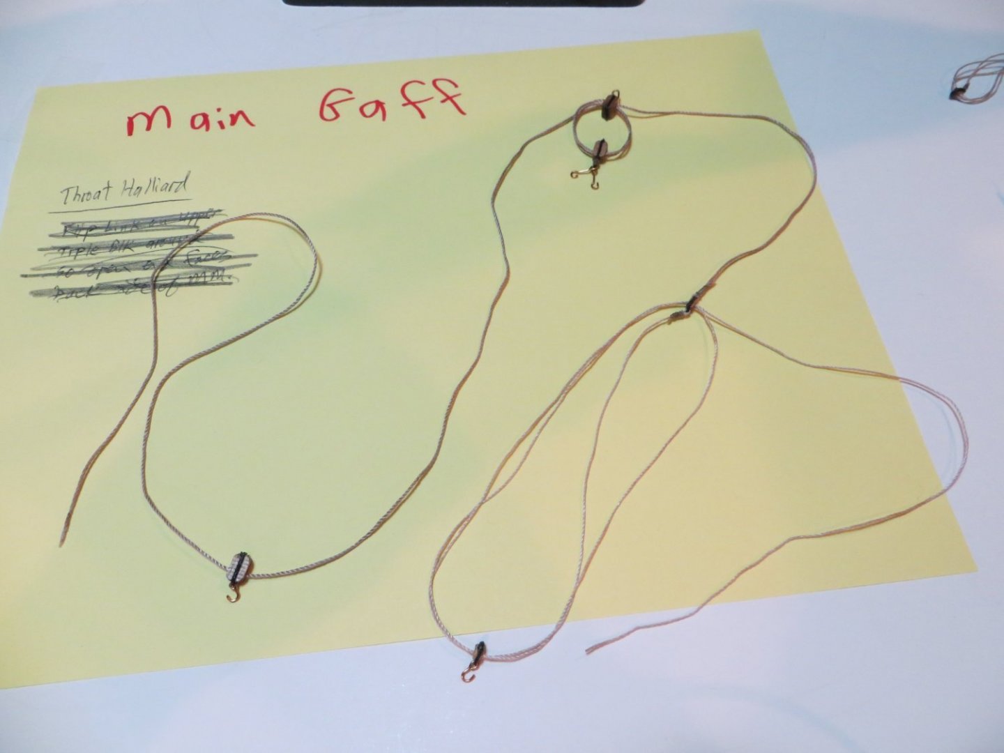
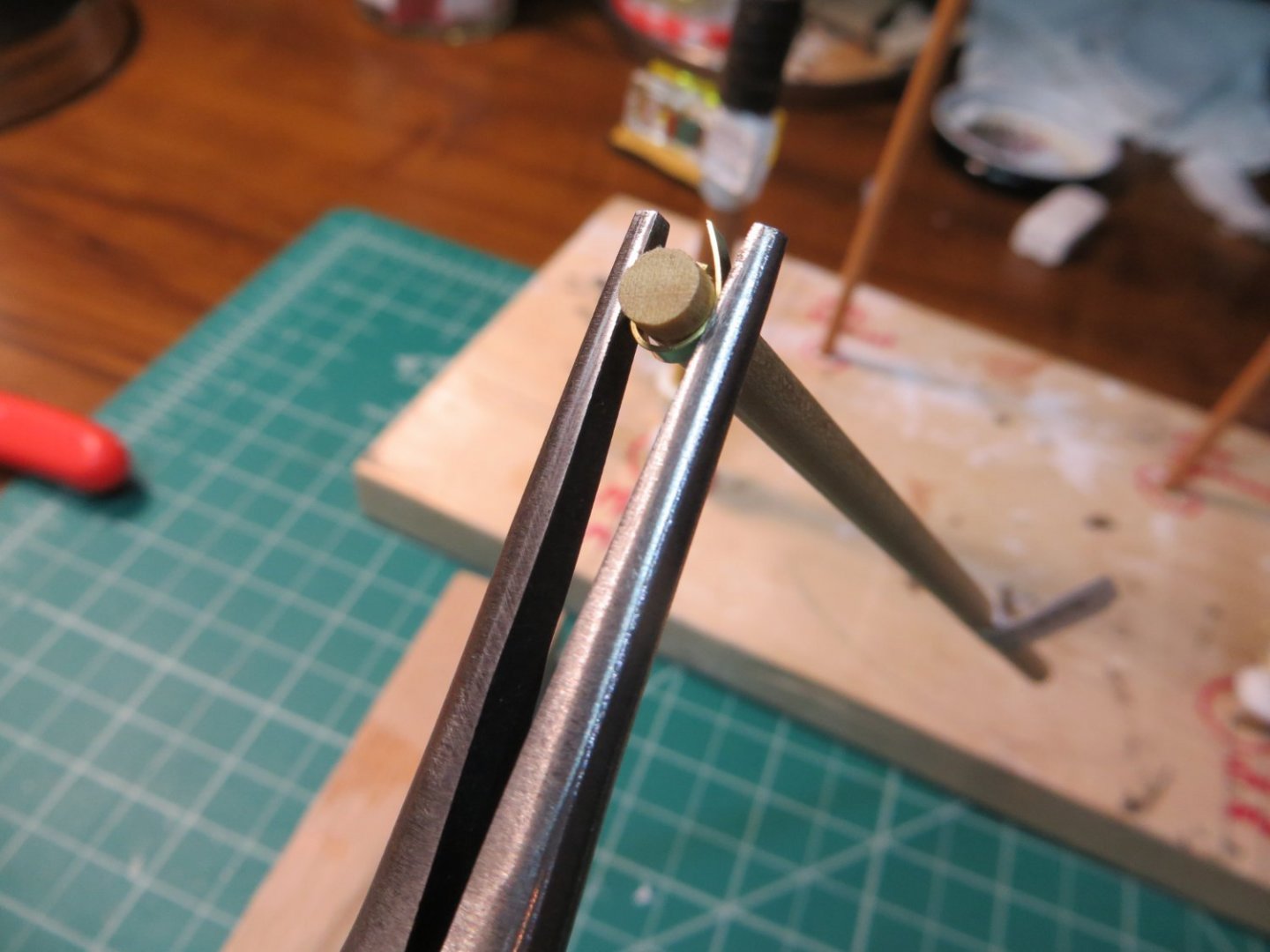
Pre-rigging the Main Gaff & How I Make S-Hooks How I Make My S-Hooks A lot of S-Hooks are used on the ship. If you are interested in a method for making them, I thought I would share mine. First off, you have to purchase a pair of round nose pliers. I did not buy them until later. I was trying to use needle nose pliers and having all kinds of trouble because the loop was not round and it was too big! Since I had so much difficulty to start, I thought there might be other newbies out there struggling like I was!! So, here is how I do it now… 1. Cut a ¾” piece of the 0.025” Artistic Wire to begin. Grasp one end in the pliers. You can increase the size of the loop you want by moving the position deeper into the plier. Push the wire around the nose of the plier until it is almost completely around, but not quite. Pic #2 shows what it looks like after bending in my new favorite pliers. Bending the wire to make the first loop: After the first loop formed: 2. I then switch to the type of pliers shown below. Place the loop end into the tip of the pliers so it is laying in the grooves with the loop almost touching the side of the pliers. Press the loop side down gently on something hard. I use a small piece of red oak wood. This bends the loop so it sits straight on top of the rest of the wire. Wire in position in the regular pliers: Bending the loop end back to center it over the straight part: After bending the first loop back: 3. Place the straight end back in the round nose pliers and using your fingers, push the wire back the opposite direction of the first loop. You will end up with the following. Wire back in round nose pliers positioned to make the second loop: After the second loop is formed: 4. Cut the excess off right where it reaches the first loop with flush cut wire cutters. Adjust the loops a bit more as needed to get the loops the size and shape you require. This method was such an improvement that I re-made most of my previous s-hooks! Completed S-Hook and the straight end that was removed: Pre-rigging the Main Gaff The Halliards on the gaffs are two of the most complex riggings on the ship. In a previous post I mentioned that I need to draw the rigging set up to visualize what I need to do and to get the details right. This was especially true here. Perhaps you don't need this to do your rigging, but it helped me! All the cross-outs for the belaying points were caused by the error in the blueprint plans (see notes in step 1) as I was trying to figure things out. Here is a pic of my sketch for the Fore/Main Throat Halliard: 1. The Main Throat Halliard holds up the fore end of the Main Gaff. It attaches to the Crane at the top and has a long run of rope that drops straight down to the deck on the port side. The starboard side forms a pendant that connects to a tackle that attaches to the main rail. [I believe the belaying pin identified on the Belaying Plan in the kit blueprint is incorrect for this rig. Belaying pin #23 should be “Main Throat Halliard” not “Peak”. Peak should be on #22. It has to be this way in order for the fairleads (on opposite sides of the trestle tree) to work properly for the Main Peak Halliard!] Here are the notes from my rigging plan… a. Working down from the Crane -> Link -> Triple Block -> Double Block -> two long S-hooks -> two eyebolts on the gaff jaws. This line needs to be long enough to cover all the Blocks involved b. Tackle Side: on the starboard side, comes more than halfway down to a 1/8" Dbl Blk that is roped to another 1/8" Dbl Blk below it which is connected to an eyebolt on the main rail. The free end is tied off to belaying pin #34 on the main rail. c. Straight Side: On the port side of the ship, the halliard line runs straight down to the deck, right next to the main mast. A 1/4" Sgl Blk is hooked to an eyebolt on the deck, and the line passes through the Blk and gets tied off to belaying pin #23 on the fife rail. Stropping the triple block at the gaff jaws with long hooks: Stropping the 2 double blocks for the tackle rig: Seizing the double block to the end of the halliard pendant: Completed Pre-rigged Main Throat Halliard; Finished Throat Halliard labelled and secured until needed for final rigging step: 2. The Main Peak Halliard holds the aft end of the Main Gaff. This too is one of the more complex rigs on the ship. 6 blocks need to be stropped and prepared for this rig. a. Preparing the Blocks: 4 - 1/4" Sgl Blks are attached to bands on the main mast using an S Hook that is seized to the Block. 3 - 1/4" Sgl Blks are attached with 0.021 black rigging line (called "Bridles") to the gaff. These lines loop around the gaff, the cleats keep these lines from slipping. The Blocks should move freely on the black bridle lines. The bridle assembly sits on top of the gaff. b. At this point the ends of the rig are the mirror image of the Throat Halliard. c. The peak halliard line is 0.021 tan rope. Run this thru both sets of Blocks first. Start w/ the lowest Blk on the mast and zig-zag bottom to top. This line needs to be centered in the blocks with enough line to cover the distance. d. Both ends of the halliard need to run through the fairleads on the ends of the spreader e. Tackle Side: this is the end that exits the lower block on the mast bands. The upper pendant is rigged the same as the Throat Halliard, between the 2 - 1/8" Dbl Blks. Except this time, it's on the Port side railing. The loose end will be belayed to pin #35 when final rigging is completed. f. Straight Side: On the starboard side of the ship, the halliard line runs straight down to the deck, right next to the main mast. A 1/4" Sgl Blk is hooked to an eyebolt on the deck, and the line passes through the Block and gets tied off to belaying pin #22 on the fife rail. g. Storing the rig for later: When done, I left the blocks and halliard on the gaff. I removed the blocks on the mast and left them hanging from the gaff. I did not connect the upper block on the tackle to the halliard line. This was necessary so we can thread the halliard through the fairlead on the spreader at the time of the final rigging. On the straight side, I did not attach the lower block to the deck. I left it hanging loose at the end of the halliard so this line could also be threaded through the fairlead. I used my jig to seize the "bridles" to the gaff behind each cleat: A Sneak Peek at the completed rigging on the Main Peak Halliard:


- 96 replies
-
- 2
-
-
- model shipways
- bluenose
- (and 1 more)
-
I've got another new post ready as I'm catching up on work that has been completed. Pre-rigging the Main Boom 1. While the boom was loose, I attached two pieces of rigging that can remain on the boom throughout. First, I attached the 2 Footropes. These are made with 0.008 black rigging line. They are connected using eye splices. They run from the eyebolts on the boom sheet band to the eyebolts on either side of the end band. 2. Second, was my first piece of real running rigging; the Main Boom Tackle. This is attached under the boom. This also can be done off the ship. Both the footropes and this entire assembly can be left on the boom when completed. I have a few pictures of the stropped blocks that were required. As this was very early on, the process I used was a bit different than what I described above. This rigging consists of a single & a double block that are attached on the fore end with a Hook and the aft end with an S-hook and a link to a band. The line gets tied off at the eyebolt on the port side of the main boom jaws. I have a few good pics that show how I made this. Below: Aft end of main boom tackle showing link -> hook -> seized double block Finished Main Boom Tackle. It actually gets tied off at the eyebolt on the port side jaw near the mast, not the cleat as shown below! 3. I then “temporarily” attached the main boom to the mast. We have to be able to remove the booms & gaffs to attach the sails later on. I inserted some fine picture hanging wire through the holes at the end of the gaff jaws to hold it to the mast while doing the pre-rigging. 4. Then I pre-rigged the Quarter Lifts. There are 2 of these. One on each side of the main sail. This needs to go next in the order to hold the boom up at the proper angle for rigging the Main Boom Sheet and 2 Crutch Tackles. The Quarter Lifts start with a pair of double blocks, S-hooked to the U-shaped shackles under the main mast trestle tree. The upper “Tackle” is made with tan 0.021” rigging line, secured to a single block and is laced to the double block. The “Fall” (end of the rope that gets tied off on the deck) from the trestle tree is tied off at belaying pins 30 & 31. The single block at the lower end of the tackle run is connected to a “Pendant” (typically the first piece of rigging at the mast, to which rigging tackles are attached; but in this case they are reversed). The pendant is made with black 0.028” line and has eye splices at both ends. These are attached to the Quarter Lift Band rings on the boom with an eye splice. Below: Top view of upper tackles with S-Hooks to shackles under the trestle tree. At the bottom are the tops of the black "Pendant" ropes. Quarter Lifts attached to the sheet band using regular hooks (not S-hooks) 5. I could work on the Main Boom Sheet next since the quarter lifts were holding up the boom at the correct angle. This rigging uses 0.021 tan line and 3 large blocks. At the boom is a Triple Block that is attached to the bail under the main sheet band. I used a split ring to connect it to the bail. There is not a lot of distance from the boom to the deck. So, stropping had to be kept tight. Next, a double block is attached to the main sheet buffer that we glued to the deck a long time ago. I used a link to connect this block to the buffer ring. The tan rope is laced between these 2 blocks. The fall end of the line coming off the triple block runs down thru a single block just forward from the boom sheet buffer, on the deck. The line gets tied off on either one of the port or starboard Bitts on the deck. I detached the hook from the sheet bail and left this rig laying on the deck for final completion later. Below: Main Boom Sheet is tied off to the starboard Bitts. 6. There is a Crutch Tackle on the port and starboard sides of the sheet. They keep the boom from moving side to side. There are 2 blocks on each side. A double block is attached using a split ring, to the sheet bail. It is laced to a single block that is attached with an S-hook to an eyebolt on the railing. When complete, I detached these from their split rings and left them hanging off the back of the ship. Below: Port side Crutch Tackle 7. Finally, I pre-rigged the Main Boom Topping Lift. This holds up the aft end of the boom. This looks like a really complicated piece of rigging, but isn’t too bad since you are starting to get the hang of things now! Here are the details straight from my rigging plan spreadsheet: a. Starting at the top. Eyebolt on main mast cap -> Shackle -> Long pendant using 0.028 Black line -> Eye splice -> S-Hook -> 3/16” Single Block b. Working up from the boom. At the Main Boom an 0.021 tan rope starts at the eyebolt on the top end of the boom. Working up: Eyebolt -> Shackle -> Eye splice -> thru the 3/16” Single Block in a. -> Eye splice -> 1/8" Double Block c. A 2nd tan rope starts at the next eyebolt inboard from the end of the boom. Working in: Eyebolt -> Shackle -> Eye splice -> Thru Double Block -> Around outer sheeve -> Back to Block -> Down to the next sheeve in -> Out bottom of sheeve and across the boom -> through fairlead -> Belayed at pin #26 on starboard side of the main boom jaw When completed, I disconnected the lower tackle and rolled up the upper pendant and left it on the mast. I left the lower tackle hanging on the boom. I don’t have any original pics of the topping lift. These are current pics as I attached this rigging permanently during installation of the main sail. Below: Upper pendant of the Topping Lift is connected to the lower mast top band with an eye splice to a shackle Lower end of topping lift with tackle lacing through blocks and sheaves at end of main boom Fall end of the tackle runs down the boom and is tied off at a belaying pin on the boom jaw


- 96 replies
-
- 2
-
-
- model shipways
- bluenose
- (and 1 more)
-
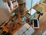
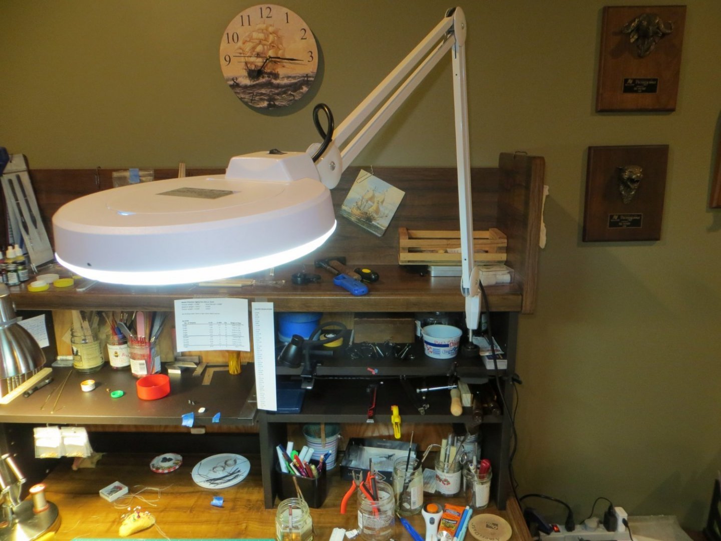
Hi Dave, I found an LED Magnifier light at Walmart for $35 that works great for me. It's called a RoHs 5X Magnifying LED Desk Lamp. It clamps to the desk or bench. But, I ended up drilling a hole in the holder and running a screw into the hobby desk. I didn't trust it to stay put otherwise! The only problem is, I can't find it on their website anymore. Maybe something to do with the supply chain issues? It is made in China! Maybe you can find it elsewhere. Here is a picture of it... Ed
-
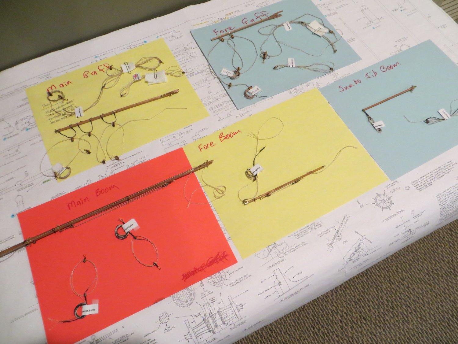
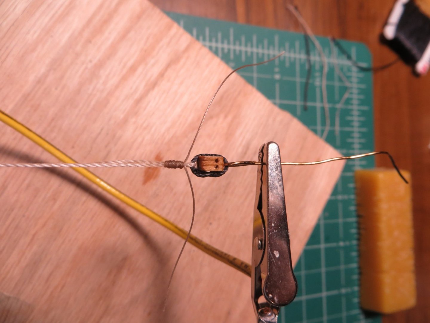
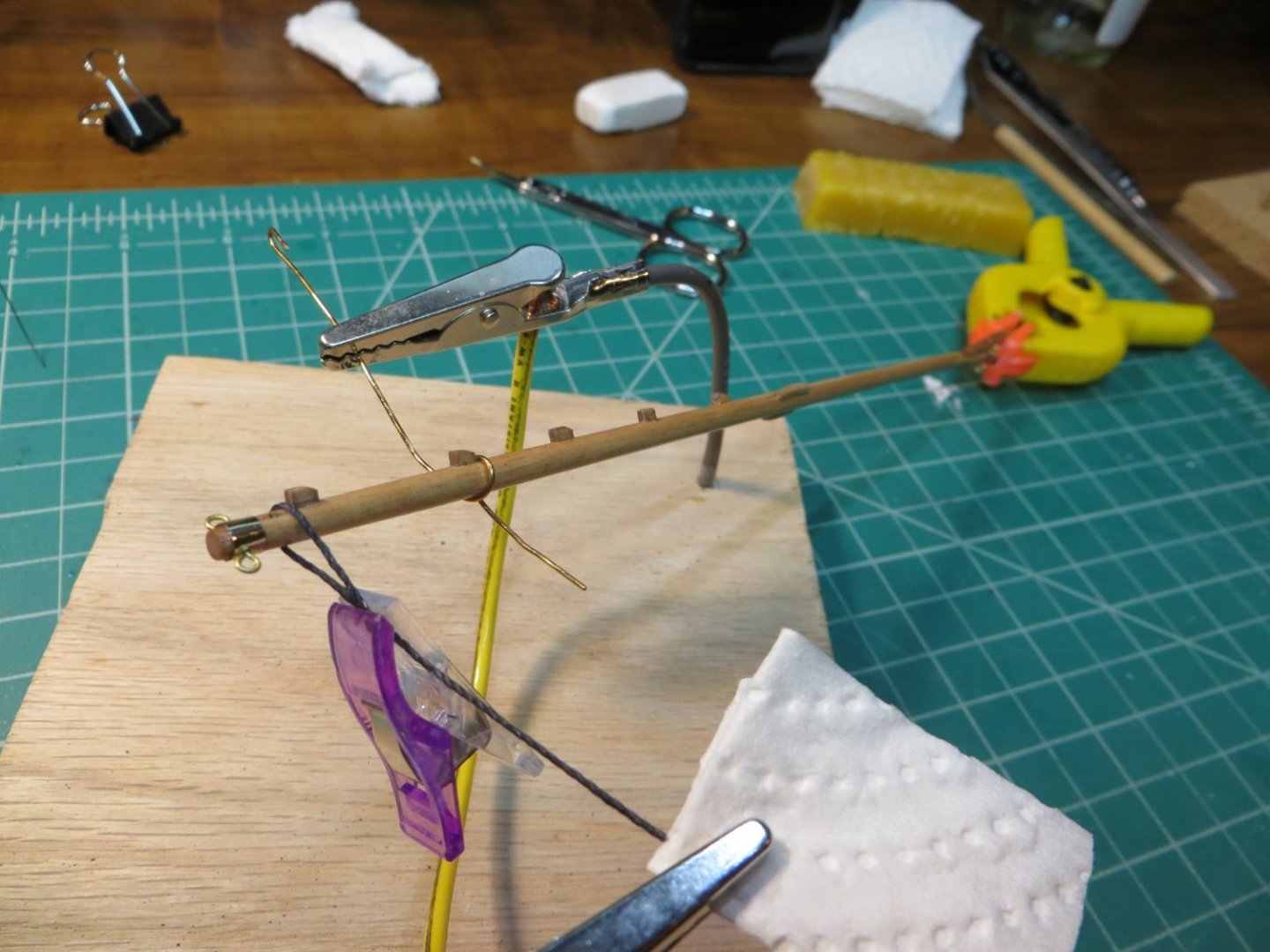
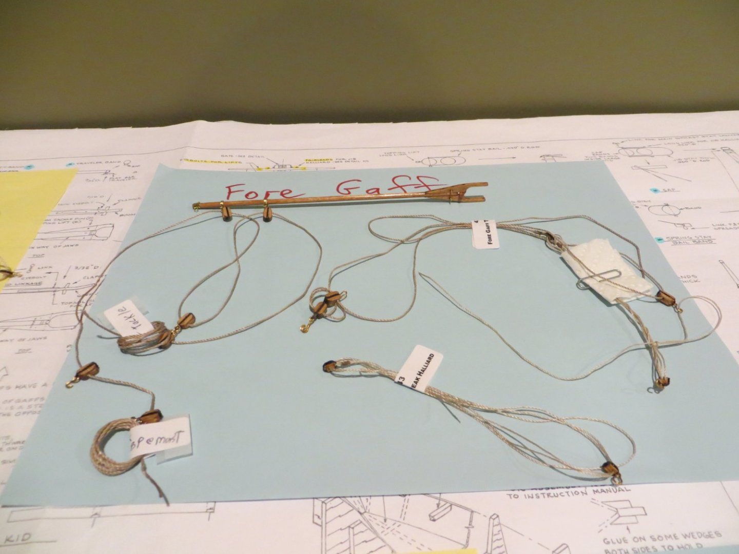
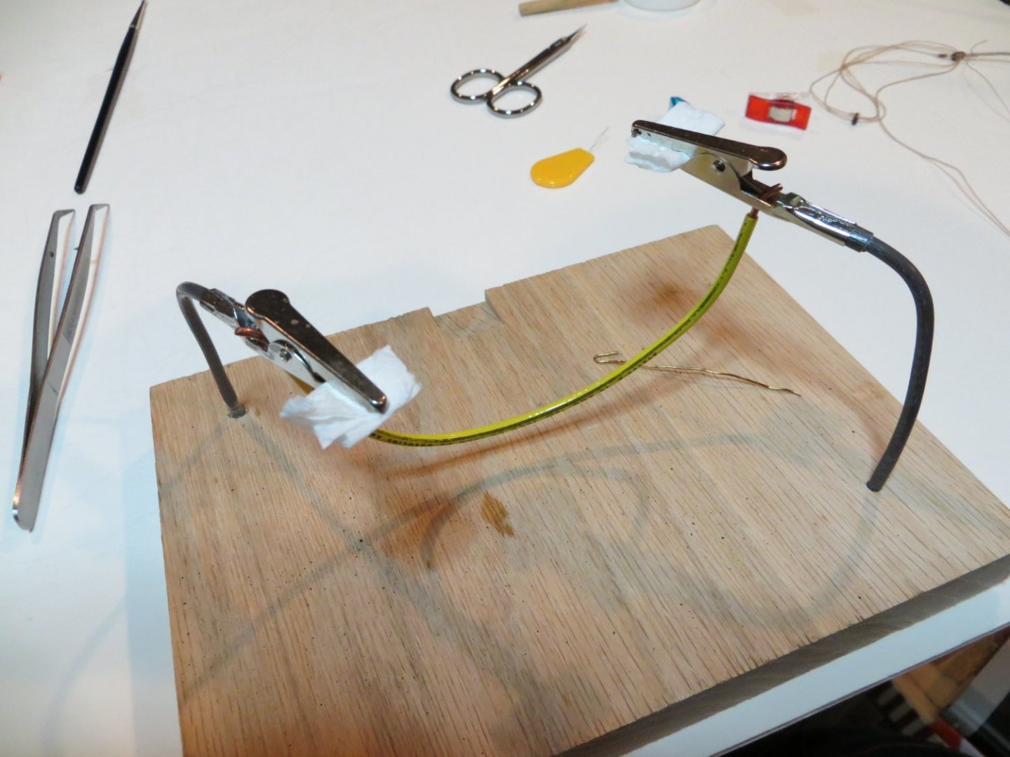
Begin Pre-Rigging for the Masts, Booms & Gaffs There are various types of rigging on Bluenose. I needed to break these down by what I could do off the ship (pre-rigging) and on the ship after the masts were set in place. Here is what I found. 1. Standing Rigging – these are the heavier black ropes that hold up the masts. This includes the Shrouds that hold the masts from the sides. They also hold the ratlines. Stays are ropes that hold the masts in the fore and aft direction. 2. Running Rigging for Spars – these are typically the tan rigging lines that control the Spars (booms and gaffs). These can be pre-rigged. This includes the following: a. Boom pre-rigging – 2 Boom Tackles, 3 Boom Sheets, 3 Tackles; 2 Crutch & 1 Inhaul, 3 Topping Lifts, 2 Quarter Lifts b. Gaff pre-rigging – 2 Throat Halliards, 2 Peak Halliards 3. Running Rigging for Sails – These tan rigging lines control the sails. These have to wait until we make the sails. No pre-rigging can be done. 4. Miscellaneous – Ratlines are horizontal lines tied between the shrouds like rope ladders. Footropes are used on the main boom & bowsprit. 5. Mast Rigging Hardware – there are a number of blocks, s-hooks, shackles, etc. that can be pre-rigged on the masts There are different pieces of hardware that you either have to make yourself or are supplied in the kit. Blocks are supplied in the kit. They come in a variety of sizes and there are numerous ways to rig them. Many builders purchase higher quality blocks elsewhere. I decided to use the ones supplied in the Model Shipways kit. I found these to be of decent quality and look good after some filing and staining. I will probably consider something fancier on my next build. Rope lines are also supplied in the kit. Many builders replace this as well. I decided to use what was provided. I think I will definitely upgrade the rope next time. The standard stuff frays easily and knots come undone. They require lots of beeswax and glue. S-Hooks, Shackles, Split Rings, Links & Deadeyes are some of the other items required. I will cover these later. Start Pre-rigging The blocks need to be stained before using them. I tested a couple of different stains and settled on Minwax “Natural”. This enriched the color of the wood without making them too dark. I just poured a little stain in a jar top and placed the blocks in batches by size, into the stain. I rolled and pushed them around for a couple of minutes to allow the stain to penetrate and cover them evenly. Then removed them to a paper towel to absorb the excess stain. Let them dry overnight and poured them back into their Ziplock bags. I continued this process until all of them were stained. I started the pre-rigging step with the running rigging for the spars. I discussed the order and rationale for this in my previous post. I started with the Main Boom, since I made that one first. I don’t have pictures of how I made every line of pre-rigging. I have some examples here below. You will be able to see the completed rigging lines in the upcoming posts. Some of the pre-rigged lines are coiled up, labelled and left on the ship. You can see these in many of my pics. Others are removed, labelled, coiled up and set aside as shown in these pictures. Pre-rigged Lines for Booms & Gaffs: I used 3 jigs for most of my rigging. I mentioned the first one with the building of the bowsprit. I purchased the Syren Serving Machine. I use this to serve rope and make eye splices. Most serving is required for making the standing rigging, especially the shrouds. Jig number two I made myself. I built a homemade “helping hands” using a piece of red oak board, a couple of alligator clips and some electric wire. I’ve used this jig more than any other. The 3rd jig is just a small square of cork board, t-pins and straight pins for stropping blocks. This also got a ton of use. Serving Machine: Homemade Helping Hands: Block Stropping Jig How to Strop a Block - Stropping is simply wrapping a length of medium weight black or tan rope around the block. I tried several methods for tying the line before I developed a technique of my own. Here is my typical block stropping process. · Pin the block on the cork board through the sheave hole/s · Place a T-pin or two for an empty loop, S-Hook, etc. at one or both ends depending on the requirement for this rig · Cut a 3 – 5-inch length of medium (0.021”) black rope for the strop. Sometimes tan is used. · Make a loop and lay it around the block · Make a strong tight knot in the loop around the block. I normally place the knot at the end if only the one other end is in use. If both ends are in use, place the knot on the side. · Dab CA glue around the strop knot. Be sure to get glue between the strop & the wood block, otherwise it will slip out of the knot. Had this happen a few times! · After drying, trim the loose ends off with a sharp hobby knife blade · After the blocks have been stropped, I use my “helping hands” jig to seize the other lines that are rigged to & through the blocks. Stropping a double block with hooks for Fore Gaff Throat Halliard: There are numerous types of block configurations. Some need hardware like s-hooks or split rings attached. Some require open loops seized on one or both ends. I had some trouble with s-hooks that were seized to blocks being to long for the space allotment on the ship. To remedy this, I stropped the hook directly to the block. On my next build I plan on using 3/0 fly tying line for seizing. I used regular thread on this build, which was perhaps too heavy. But, it’s too late to change it up now! This post is getting too long. I will cover the actual pre-rigging of the spars in the next post.


- 96 replies
-
- 2
-
-
- model shipways
- bluenose
- (and 1 more)
-
Wow! Looks awesome Dave. I knew you would come up with something special.
- 389 replies
-
- 1
-
-
- bluenose
- model shipways
- (and 1 more)
-
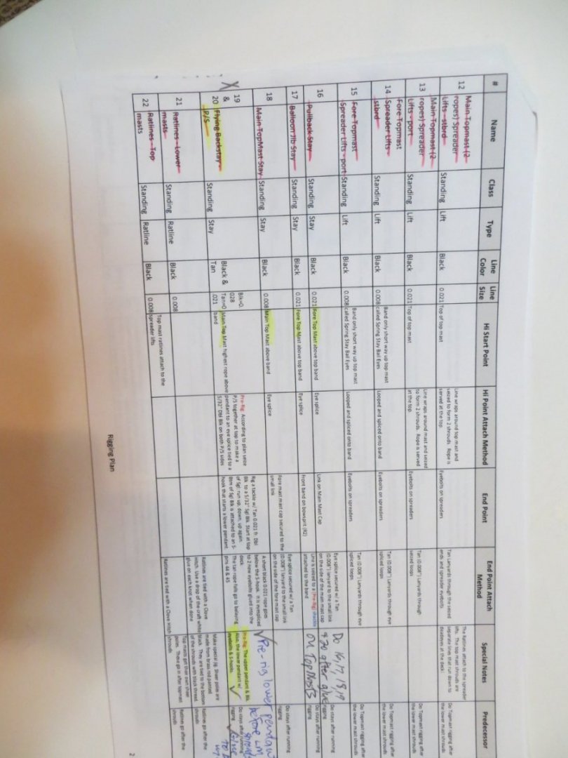
Rigging Planning and Pre-Rigging As I’ve done for the most part throughout this build, I followed the process outlined by Suburban Ship Modeler. He decided to do what many shipwrights do…pre-rig as much rigging as possible before mounting the masts on the ship. The advantage to doing it this way is you can get around the mast or spar more easily and at better angles. You don’t have to reach around or through existing rigging lines. You can seize lines off the ship. The disadvantage is you need to use more rigging line because you can’t precisely measure the length required for each line. Unfortunately, SSM does not explain too much about how he decided what can be pre-rigged or the order for doing the pre-rigging. So, for this part I followed my own instincts. Here was my thought process. My General Rigging Plan 1. Rigging Spreadsheet – I created an Excel spreadsheet identifying every rigging line on the plans. (Below there is a pic of one page to show you what this looks like) I made columns showing the line name, line type, color, size, high point start and attachment method, end point methods. I also attempted to determine what could/should be pre-rigged ahead of time. I spent a lot of time doing this but I didn’t end up using it as much as I thought I would. However, it was a great learning tool that prepared me for the task ahead. I did make labels for each line from this. I attached the label to each line after making them. What I ended up doing/using the most was a sketch of each line before I began making it. I needed a visual picture to figure out how to actually set-up the stropping of each block, seizing for each line, the length needed for each line, etc. 2. Attach all the blocks, shackles, links, etc. to the masts, booms, gaffs and even the rails and decks with the masts off the ship 3. Attach as many of the rigging lines as possible to the masts, booms, and gaffs 4. Make each line with extra length, and either coil the lines up or leave them loose so they can be removed from the ship and stored until I needed them later 5. Tag each line with a label based on the rigging spreadsheet 6. When running pre-rigging is done, mount the lower masts to the ship. Topmasts were mounted later. 7. Install the shrouds and attach them to the deadeyes on the hull. 8. Install the rest of the standing rigging (this varied depending on the line, more on this later) 9. Install the Ratlines 10. Install the running rigging for the booms & gaffs 11. Install the running rigging for the sails at the time when I make each one Sample of a page from my Rigging Spreadsheet: My High-Level Plan for doing Pre-Rigging 1. Work from the Deck upward (booms then gaffs). And inside-out from masts to railings 2. Pre-rig the running rigging (sheets, tackles, lifts) on the Main Boom, Fore Boom, Jumbo Jib boom, Main & Fore Gaffs. Temporarily rig the boom or gaff to the mast, one at a time. Make the rigging lines for each spar and on the deck. Remove the boom/gaff, coil up and label each rig. 3. Pre-rig the lower mast shrouds at the top. Coil them up for later. 4. Pre-rig the Spring Stay, Jib Stay and Jumbo Jib Stay on the lower mast caps. Coil for later. 5. Pre-rig blocks, fairleads, eyebolts on lower masts, bowsprit & deck for sail halliards/downhauls. 6. GLUE the LOWER MASTS (Not the topmasts, to leave room to work on lower shrouds) 7. Rig the deadeyes for the lower shrouds 8. Install Shear Poles, Ratlines & Running Lights for Lower Mast shrouds 9. Install the Spring Stay only. All 3 Jib Stays need to be loose to thread the sail HANKS on. 10. Install mast hoops for topmasts 11. GLUE the TOPMASTS permanently 12. Fully Rig the Topmast Shrouds & Lifts (Topmast shrouds go before stays in the order at top of mast) 13. Install all the Lower & Topmast Stays, except jibs (Pullback, Main Topmast and Flying Backstays) 14. Install Ratlines for Topmasts 15. Finally, complete the rigging associated with each sail. Complete all rigging one at the time when I connect each sail to its boom and gaff, then the ones without spars. Next Step: Pre-rigging the Booms & Gaffs I began pre-rigging the booms & gaffs. I will explain what I did and the order in which it was done in future posts. I took me over 100 hours and 40 calendar days to complete this pre-rig step. This does not include study time! The shrouds and standing rigging will be covered after the running rigging on the spars.
- 96 replies
-
- 3
-
-
- model shipways
- bluenose
- (and 1 more)
-
Thanks Bob! I think that falls under the category of "even a blind squirrel finds a nut now and then"!! I kind of stumbled into that method through a lot of trials and errors.
- 96 replies
-
- 2
-
-
- model shipways
- bluenose
- (and 1 more)
-
Thanks Guys! I create these construction notes for my own use before I start building each stage. They are based on the information I find from other builders and my interpretation of the plans. When finished, I modify them slightly to make them easier to follow from the readers perspective. I'm glad to hear that they will be useful to you and hopefully other shipwrights! Dave & Per, you've both been a big help to me. So, thanks. Per, I am deleting the original posts for these entries that I had posted as Status Replies by mistake. From what I've read on the Forum, a moderator has to delete the empty shells that are left behind. It will take me a few more days to clean them all out. When I'm done, can you help me delete these empty posts? Thanks.
-
My Bluenose 1 Build Log has been moved to the "Topics" area where it belongs. I am deleting the build log posts that I mistakenly posted as "Status Updates".
Here is the title of my ongoing Build Log:
Bluenose I by Ed Ku20 - Model Shipways - 1:64
-
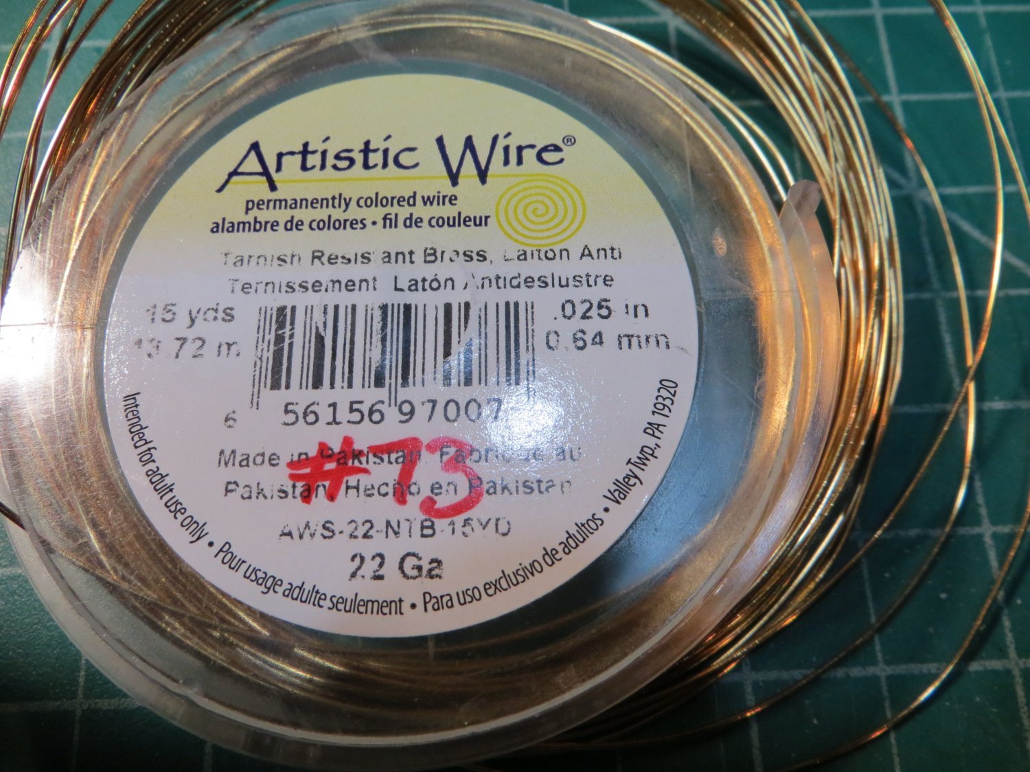
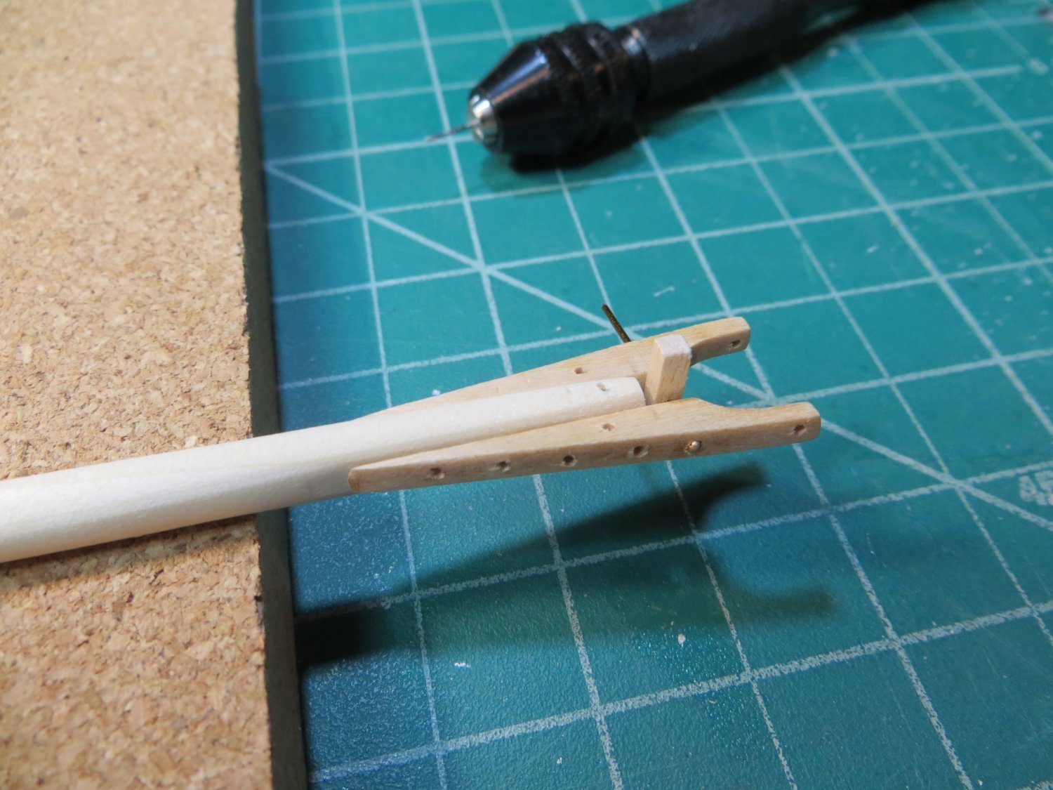
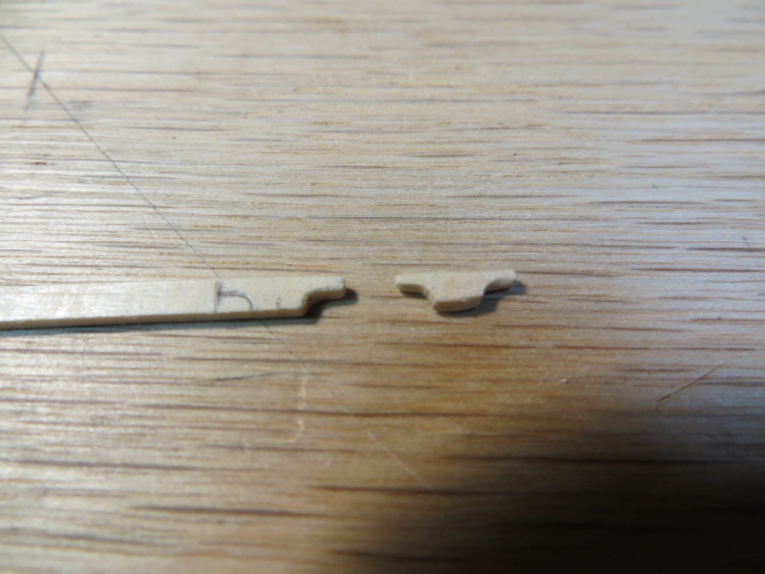
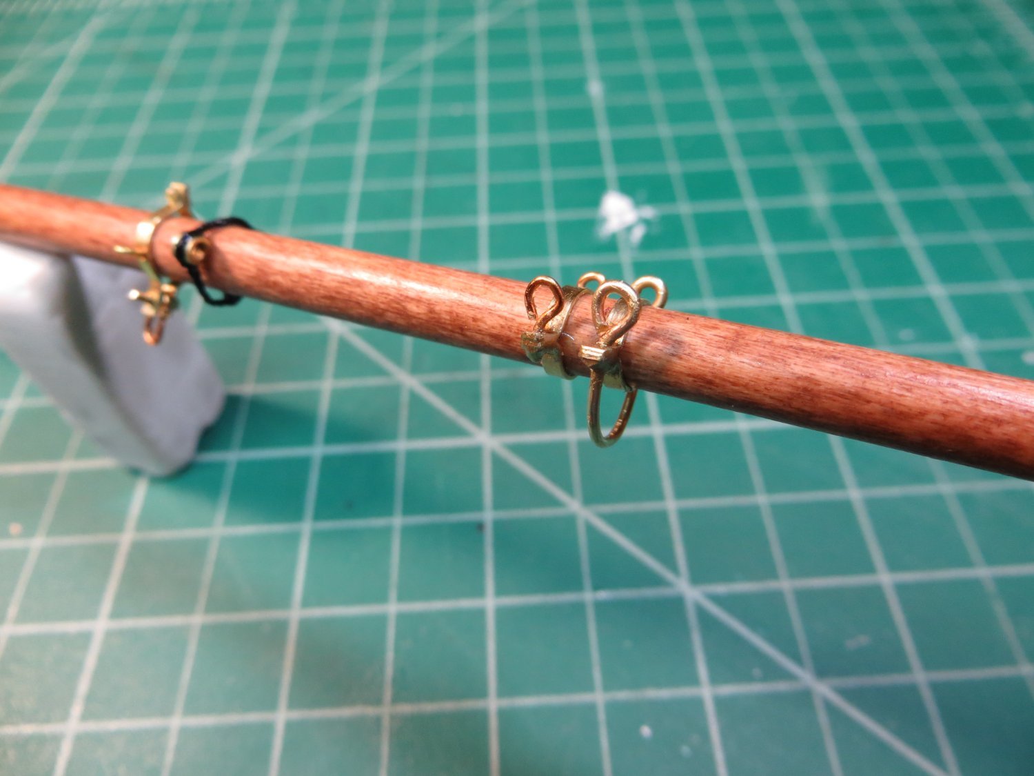
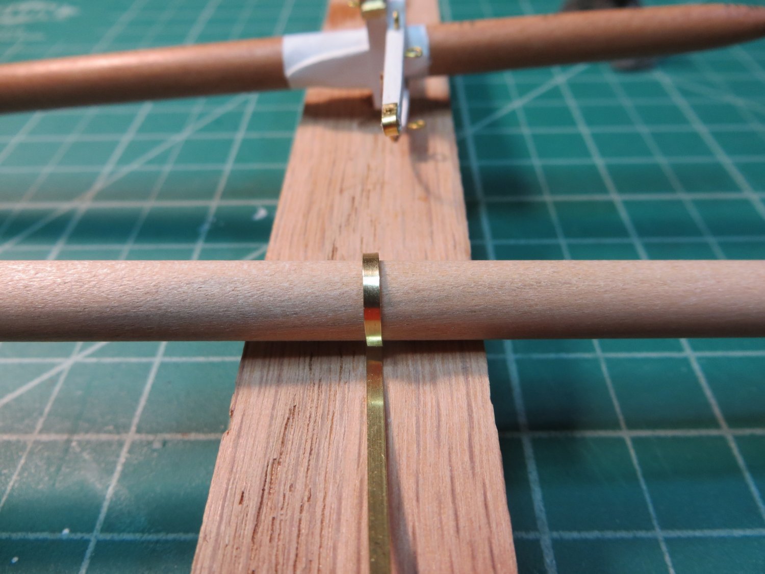
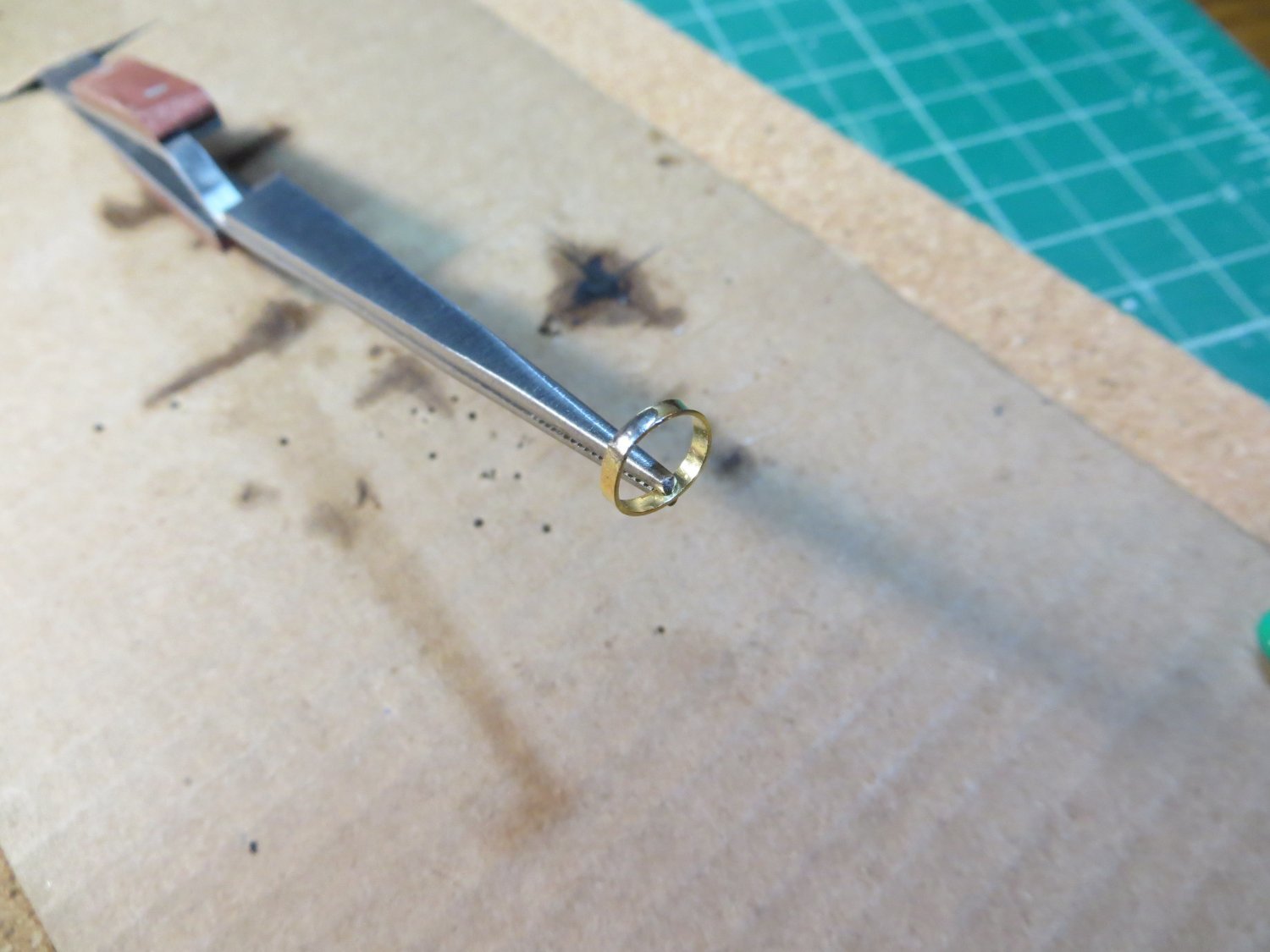
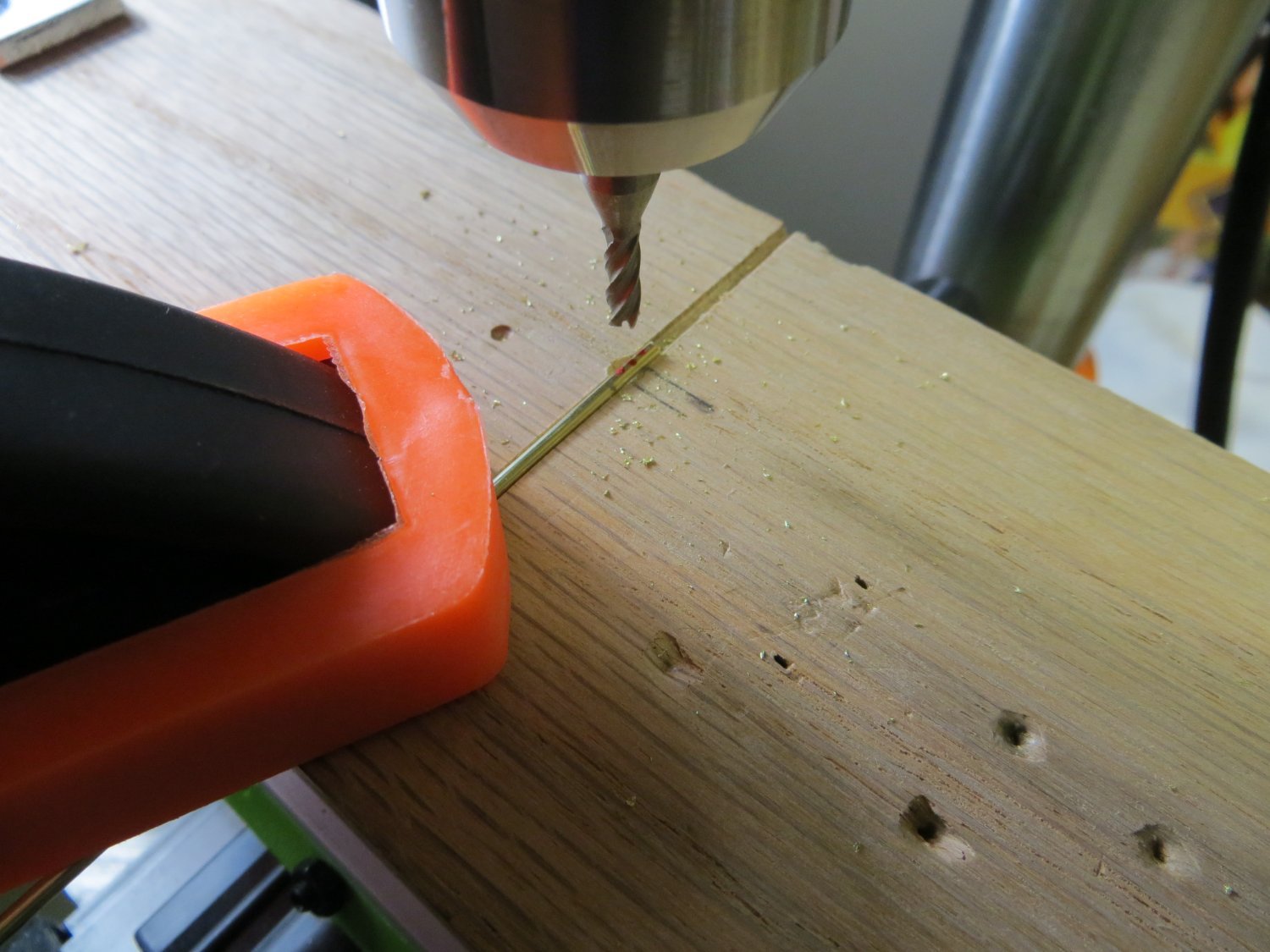
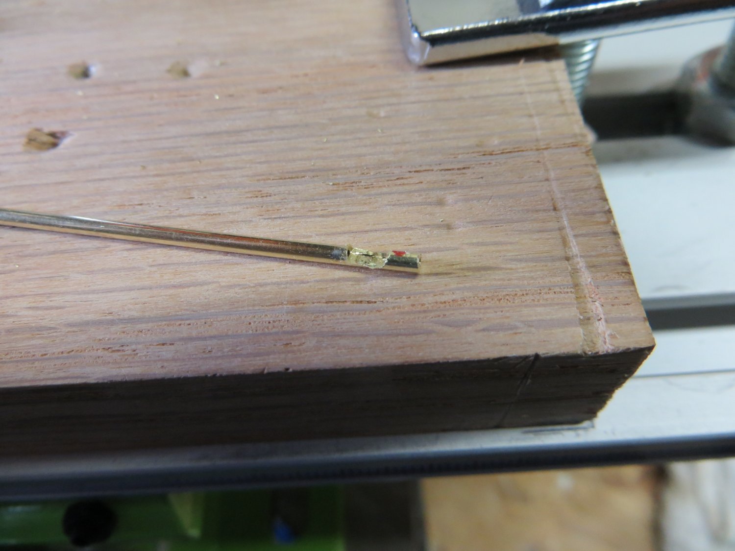
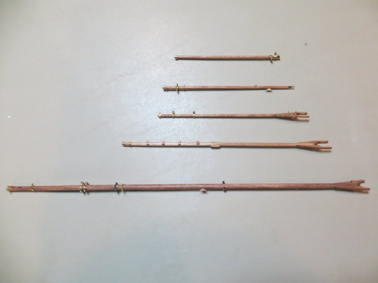
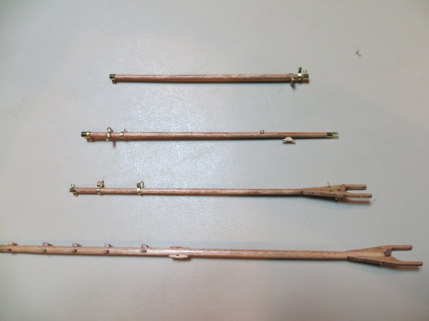
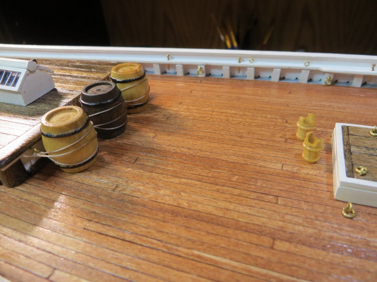
Originally posted on Dec. 27, 2021 This completes the move of all my previous posts that were mistakenly added as Status Updates. I need to create some new posts to catch my build log up to where I am actually at with Bluenose. Building the Booms & Gaffs – Continued Fore Boom 1. Shape the fore boom with sanding tools according to the plans. Use a 1/8” dowel. Stained with Minwax Cherry stain. 2. Bracket for gooseneck @ mast. The fore boom doesn’t have jaws. I used a piece of 1/16” brass strip and bent it into a U-shaped bracket that the gooseneck will be attached to with a nut & mini-bolt. I attached the bracket to the tip of the boom with a mini-bolt & CA glue. I purchased a roll of metallic gold tape on-line. I wrapped this around the end to simulate an end cap. It looks just like a brass band. 3. Boom Tackle Band (per the plans this is similar to the jumbo jib boom clew band). This is the fitting farthest inside the boom. Use a 1/16” brass strip with a mini-bolt and nut on the flange. I simply wrapped the strip around the boom and drilled a hole for the nut & mini-bolt. The below pic shows my latest method for drilling holes to make pieces like the Boom Tackle Band. I cut the strip leaving some excess for folding over the ends. Next, I shape the brass strip around the boom. Then, I wrap the excess ends with some Tamiya tape. Make a pilot indentation with the fine point punch where the hole needs to go. I clamp the taped end between a couple of pieces of 1/16” thick sheet wood. The bottom sheet keeps the round end up off the XY table. After making a pilot hole, drill it with a #64 drill bitt. Next to it is the fore end of the Jumbo Jib Boom with the loops that connects it to the Traveller bar. This boom is covered further below. 4. Fore Sheet Band – this was made the same as the main sheet band, with a wire bail at the bottom. I used the smaller Art Wire for this. Below is a good pic of this in mid construction. 5. Clew Band – Band with a mini-bolt and nut on the top flange. This is made just like the Boom Tackle Band above. 6. Topping Lift Band – brass band at the aft end of the boom with an eye bolt on the top. I wrapped the gold tape around the end of the boom and drilled the hole on top with my vise drill. 7. Wooden Cleat – I made 2 cleats at the same time when I made the main boom. I inserted the brass pin as before to hold the cleat more securely. I glued it in place. The completed aft end of the Fore Boom in order from forward (right side) to aft (left end) Boom Tackle Band, Fore Sheet Band, Clew Band & Topping Lift Band Jumbo Jib Boom 1. The jumbo jib boom requires minimal sanding according to the plans. Use a 1/8” dowel. I applied Minwax Cherry stain. 2. Wrap the end of the boom with the gold tape. This needs to be wider than the standard brass strip, so the tape worked perfectly. Drill 4 holes in the bottom side of the boom, through the tape. I formed 2 U shaped pieces of the “Artwire” and glued them into the holes. This end will be attached to the traveler bar on top of the bowsprit. I've spoken frequently about the 0.025 inch "Artistic Wire" that I use. This stuff has been indispensable for me. I've used it all over the ship. I've been meaning to take a picture of it for you. Found it on Amazon quite a while back in the build! 3. Jumbo Jib Sheet Band – same as the fore sheet band, with a wire bail under the bottom. 4. Clew Band – Band with a mini-bolt and nut on the top flange. No flange on the bottom. 5. Topping Lift Band – brass band at the end of the boom with an eye bolt on the top Fore Gaff 1. Shape the fore gaff with sanding tools according to the plans. Use a 1/8” dowel. Sand the jaws to remove laser char, make the clapper and drill holes before attaching the jaws and inserting the brass pins. Very similar to the main boom. Apply Minwax Cherry stain. 2. Three bands are required: a. Peak Halliard Bands – 2 of these are needed. Band with a mini-bolt and nut on the top flange. No flange on bottom. Similar to the clew band on the jumbo jib boom. b. End Band – simple band with eyebolts on the top and bottom 3. Drill a small horizontal hole through the gaff, next to the end band, for attaching the topsail. Main Gaff 1. Shape the main gaff with sanding tools according to the plans. Use a 5/32” dowel. Also sand the jaws, make the clapper and drill holes same as the fore gaff. Note the shape of the clapper. It is rounded with the ends tapered where it faces the jaws. Minwax Cherry stain after assembled. 2. End Band – simple band with eyebolts on the top and bottom, same as fore gaff 3. Stop Chocks for Peak Halliard Bridles (P/S) – These 2 are larger and have a hole drilled in the center. I made these from 1/32” square strip wood. Sand them to round off the outer edge toward the ends. 4. Small Stop Chocks – 10 smaller stop chocks run from the above toward the end of the gaff. They are in pairs at 4 & 8 o’clock. Glue them on first, then sand to shape. The edge facing the jaws is tapered. 5. Drill a small horizontal hole through the gaff, next to the end band, for attaching the sail. Completed Main Gaff at the mast end. Completed Booms and Gaffs I purchased a few wooden barrels and wooden buckets from Modelers Central. I also bought my “parrel beads” that go around the outside end of the jaws from them. The barrels were 15 x 17mm. The buckets I bought were 5 x 7mm. I stained them with Minwax Natural stain and painted the hoops with black enamel. I also sealed them with polyurethane. I glued them to the deck and wrapped some rope around the barrels. I think this adds a nice touch to the deck. All the major "construction" steps are now complete. Next up is rigging and sails!


- 96 replies
-
- 3
-
-
- model shipways
- bluenose
- (and 1 more)
-
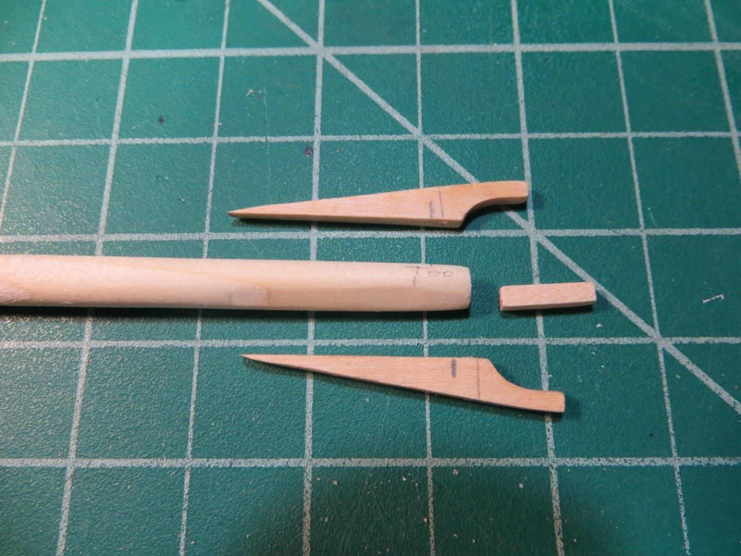
Originally posted Dec. 23, 2021 Building the Booms & Gaffs – Main Boom Construction Steps The main boom is made with a tapered dowel rod. Jaws and a “clapper” hold the end of the boom to the main mast. The jaws are provided in the kit. It took a little measuring to determine which set of jaws belonged to which boom/gaff. If you lay them down on the plans, you can distinguish the main boom from the matching jaws for the 2 gaffs because they are larger. These need to be separated and then sanded to remove the laser char. The plans for these 5 pieces are at the model scale. So, I was able to use the measurements directly off the plans to position the various pieces on the boom. 1. The dowel needs to be tapered toward both ends. The two sides where the jaws are attached is flattened using files and sanding sticks. Check the plans for tapering details. The clapper is made from a 3/32” square x 3/8” long piece of strip wood. 2. First thing I did after preparing the dowel was to install the Sheaves at the far end. I was very worried about carving these holes in the dowel. If things went badly, I didn’t want to ruin hours of work done beforehand. So, I left the dowel intentionally long. If I did mess it up, then I can cut the end off and try again without starting over! a. The Sheaves were made by drilling 2 holes close together, through the dowel. Sorry I don't have any pictures of this step. b. I then filed out some of the wood in between the holes, but left a bit of wood in the center to simulate the “roller”. I think they actually came out rather well! 3. Before gluing on the jaws, I drilled all the holes: a. 4 on outside edge of each jaw for the brass rod “pins” that will be inserted b. 5th one on outside edge of jaw for the clapper needs to be aligned through both sides c. 1 hole on top of each jaw for belaying pins d. 1 hole goes in the dowel rod between the belaying pins for an eyebolt e. Holes also need to go in at the outside of the jaw tips for the parrel beads. These are angled slightly to wrap the rope with the parrel beads around the mast. 4. Once the 4 pieces were prepared, I glued on the jaws with PVA wood glue. After the glue set, I extended the holes into the dowels and inserted brass rods for bolts. I filled the holes with CA glue before inserting the rods to provide extra strength to hold the jaws. 5. Stain everything with Minwax Cherry. I actually did this in between gluing the jaws and inserting the pins. After the stain dried, I inserted the pin that holds the clapper. It needs to be able to tilt back and forth against the mast. Make sure you work it back and forth occasionally as the glue dries. Boom, Jaws & Clapper ready for assembly Jaws glued in place and pin inserted for the clapper Pic of the completed jaw end of the main boom 6. Wooden Cleat is attached to the port side of boom. I made it 15/64” long x 3/64” thick. No dimension given for how tall, so used my best judgement. After I knocked the cleat off while working, I inserted a brass pin made from a length of the cut-off end of an eyebolt. This secured it better. I made a couple since another is needed for the Fore Boom. Carving the cleat from a piece of strip wood 7. 2 Brass Staples go on P/S sides near the cleat. These are used to hold the “rope eyes” for the lazy jack line. Insert a black rope with an eye splice on each end through the staples. Getting this to come out the correct length was a challenge. A bit of CA glue was used to hold it in place. Wooden Cleat attached & the brass staples 8. 2 Bullseye Fairleads go on P/S sides. Stbd one is for the Topping Lift line. Plans show 3/32” D. I made these from a piece of brass tube. I first filed a groove around the circumference of the tube to hold the rope. Then I cut the slice of tubing off and repeated the process. Each fairlead tube is held in place with a loop of rope, in the groove, and tied off around the boom. CA glue is needed to hold everything in position. 2 Bullseye Fairleads carved and cut from brass tubing 9. The Boom Tackle Band is made from brass strip, eyebolts, and a link. I cut a length of 1/16” brass strip and folded it in half. I drilled a hole just below the fold and inserted a brass rod pin. The strip was spread open and fitted around the dowel. Holes were drilled in the P/S sides for eyebolts. Holes were also drilled in the bottom. I used one of the brass bolts/nuts that I ordered some time ago from ModelMotorCars.com. Add a link on the bolt between the sides of the brass strip. Bullseye Fairlead & Boom Tackle Band installed on main boom 10. Quarter Lift Band is the next piece in the line. I used more brass strip. Folded over on one side and soldered on the other. Before soldering, I drilled holes on each side and inserted an eyebolt in each hole. I soldered everything together and filed down the bottom a bit to hide the pointed end of the eyebolt. 11. Main Sheet Band is made very similar to the quarter lift, except that it has a wire bail on the bottom for the boom sheet rigging. I decided to use the heavier brass rod to make this one. After the band was shaped and holes were drilled, I bent a piece of the rod to fit the shape required. The ends were twisted into the eye rings that will be used to hold the footropes at the end of the boom. The bail was soldered together with the sides of the band. Below is a good pic of the completed band before it was slipped onto the boom. I’ve been leaving the folded side with the fold. The bands seem to be a lot sturdier, and I don’t think this will be noticeable on the completed ship. Main Sheet Band ready for installation Quarter Lift Band & Main Sheet Band 12. Clew Band is made from brass strip with a mini-bolt & nut through the top flange. This hold the aft end of the main sail. 13. End Band goes at the far end of the boom. 2 eyebolts are added P/S for footropes. 1 eyebolt is added at the top of the band for the topping lift line. Add 1 more eyebolt in front of the end band When everything was in place, I smoothed some of the scuffs and gouges created from scraping the bands on the boom. I re-stained a few spots and gave the entire boom a protective coat of wipe-on-poly. Since they are so similar, I did the rest of the booms and gaffs somewhat together. More pictures of the main boom are found in the next post.

- 96 replies
-
- 2
-
-
- model shipways
- bluenose
- (and 1 more)
-
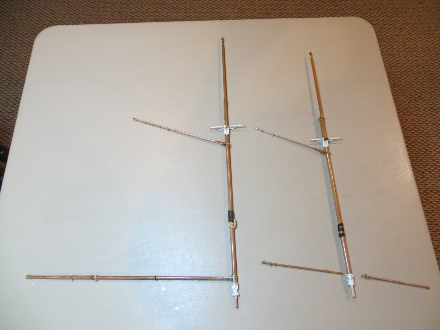
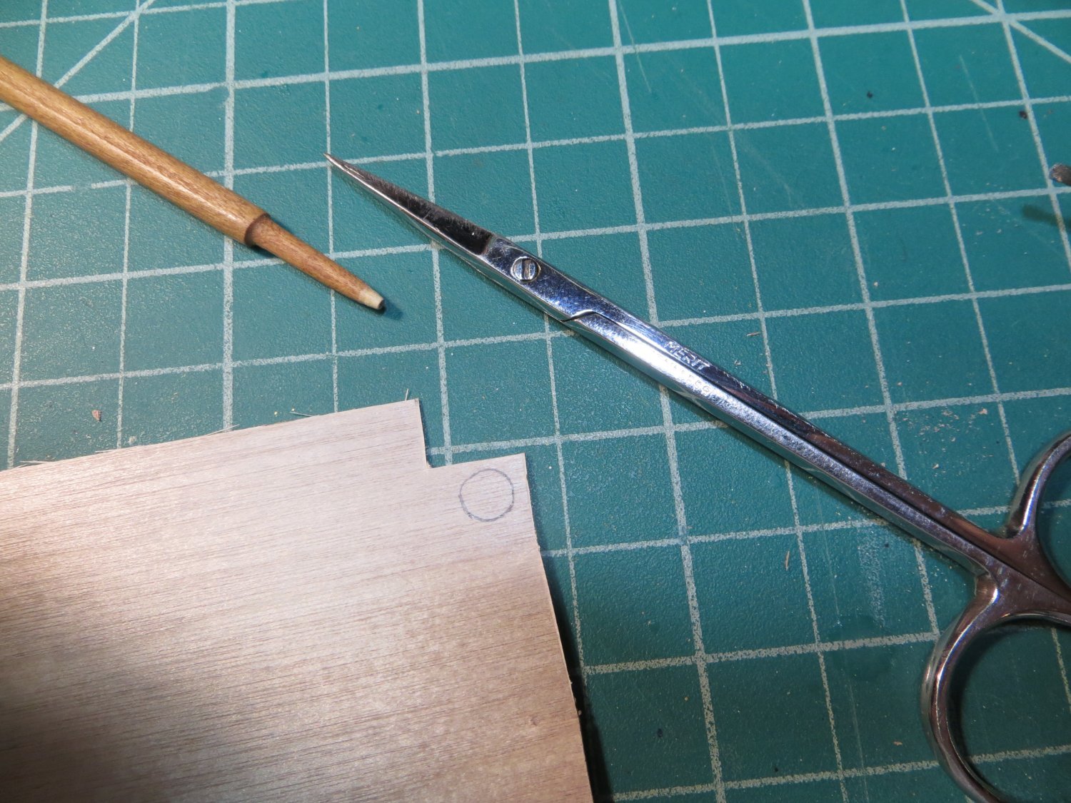
Originally posted Dec. 19, 2021 Top Masts The final step for mast construction is to complete the top masts. I had shaped these according to the plans earlier. The bottom must be sanded to be square on the aft side and rounded in front. The shape needs to fit into the hole in the front of the trestle trees. The top requires a shoulder to be sanded in and the tip comes to a bit of a point. There is just 1 band at the top, below the shoulder. Eyebolts were added to the fore & aft sides of the bands. The process for making the bands was done the same as those on the lower masts. The tricky part was making the trucks and gilded balls for both masts. After trying a couple of methods, I ended up using a thin sheet of birchwood that I bought for the dories, to make the truck. It’s 3/128” thick. I took the diameter of this disk from the plans. I was able to use a curved pair of scissors to rough cut it out and then finished it with a sanding stick. 2 pairs of holes are required on each one for the flag halliards. Since the wood is so thin, I had to use a lot of care with the pin vise. Pic showing the carved and finished topmast; Also, the birchwood sheet with the truck penciled on it The Truck after cutting it out of the sheet Truck after using the sanding stick Finished piece fitted on the topmast The gilded ball was made from the end of a small dowel. I used files and sanding sticks to make the shape. It took a couple of tries to get the size right. When done, I carefully sawed the ball off the dowel. A small hole was drilled into the bottom of the ball using the pin vise. I started with the smallest bitt I had and increased the size until it fit onto the tip of the mast. Gilded Ball carved on the dowel & ready to be cut off I skipped 2 of the steps at this point. I did not drill the sheaves or insert the iron fids. The sheaves were for raising the topmasts in place during ship construction and have no rigging required. And I plan to glue the topmasts into position on the lower mast when the time comes. When done, I stained the masts with Minwax cherry and finished them off with some wipe on poly like the rest of the wood on the ship. The completed Topmasts dry-fit on the lower masts

- 96 replies
-
- 2
-
-
- model shipways
- bluenose
- (and 1 more)
-
Dave, awesome job on the bowsprit! It looks great. However, you've given me a case of tool envy!! Gonna have to think about investing in a milling machine for my next build.
-
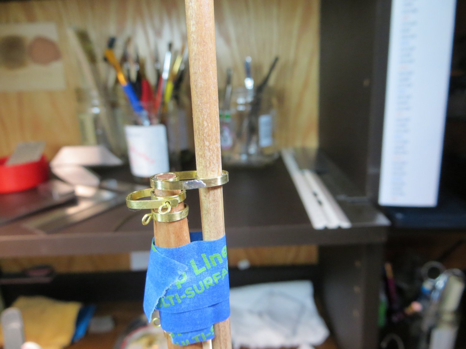
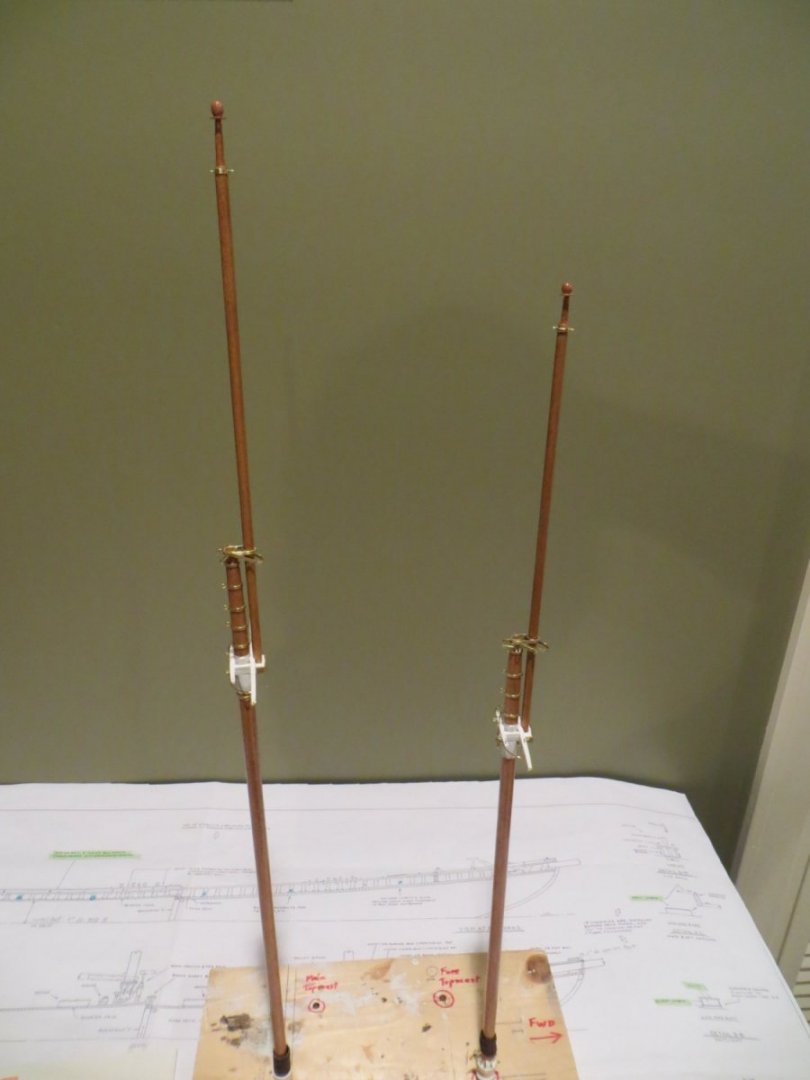
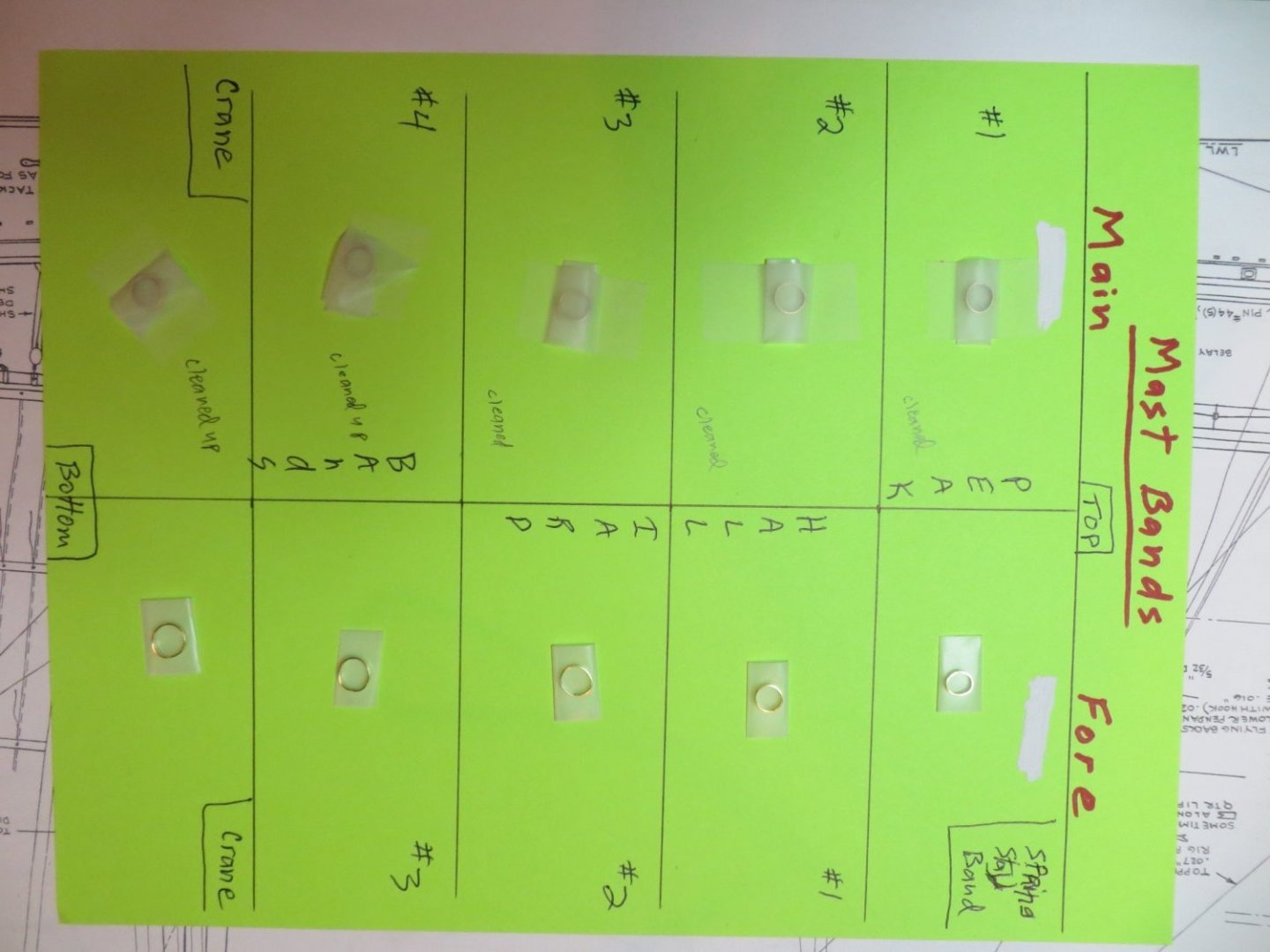
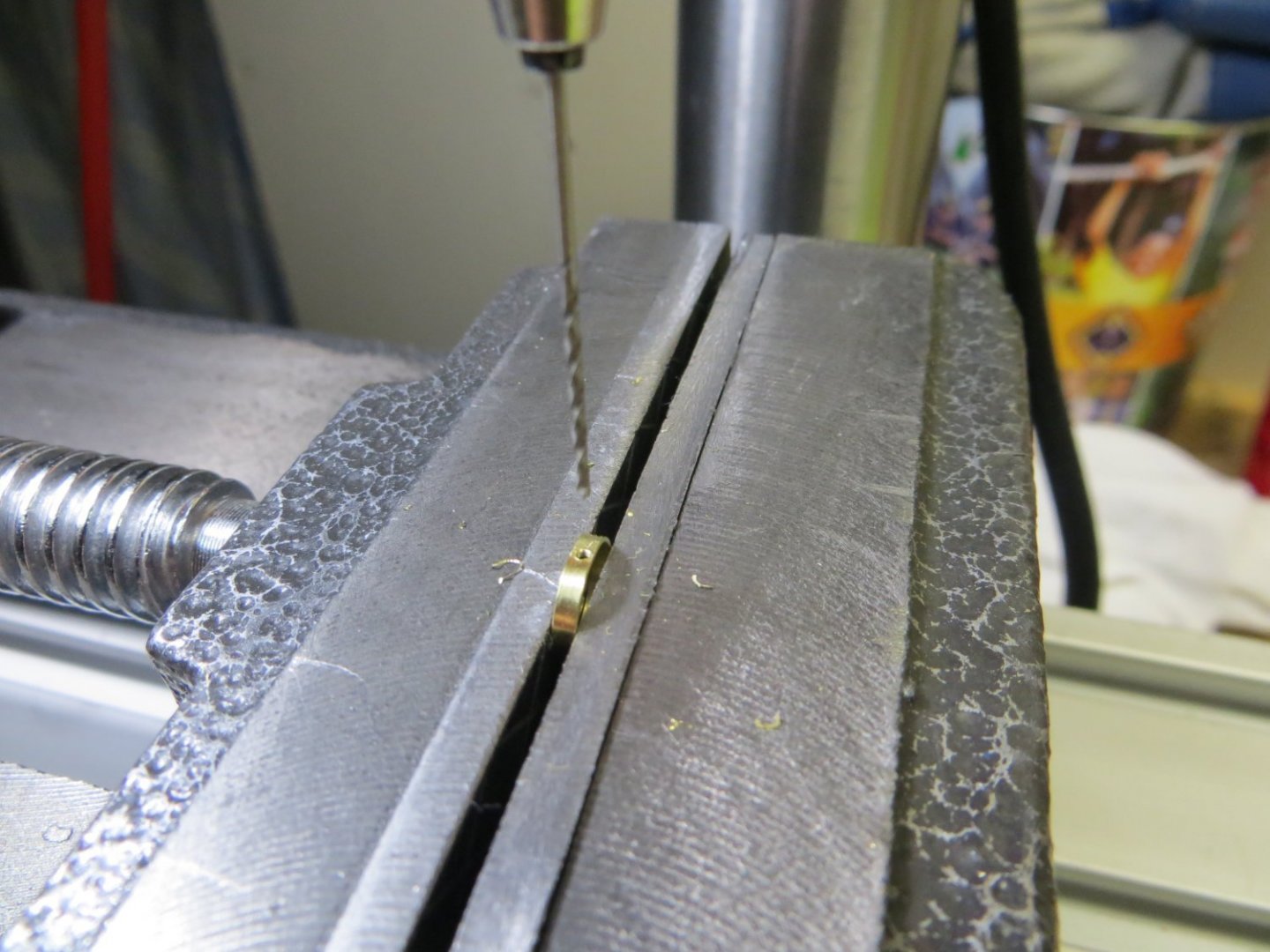
Originally posted Nov. 18, 2021 Brass Mast Bands, Cranes & Caps This step involves making lots of metal bands, then drilling holes in them! All are made from standard 1/16” brass strip from the kit. Each one needs to be custom fit on the mast due to the tapering. I slowly improved my soldering skills and ability to drill a precision hole with the drill press as I worked my way through these bands. For all you newbies like me, here are a few tips I learned along the journey! Make bands too large to begin and trim until it fits. File the open ends square for more soldering surface area. If you make little solder balls, your iron is too hot! Solder goes where the flux is. An iron that's too hot also melts the flux too fast. Once I found the right temperature I taped the temp dial in place, so I didn't have to mess with it again! Late in the game I learned how to apply a little solder to the tip of my soldering iron and then touch it to the brass joint. My joints got a lot neater when I mastered that versus holding the solder with the spool against the brass and the soldering iron in the other hand. Always make a pilot hole with a fine point punch before drilling your hole. Construction Steps 1. Mark the locations of all the bands according to the plans. I recommend that you do this before assembling the trestle trees on the masts. I laid the mast against the plan and marked each location 2. Custom size each of the bands on the mast using these steps: a. I start by twisting the end of a brass strip with a pair of smooth pointed mini-pliers to get the curl started. Then wrap it around the mast-sized dowel with my fingers to get the approximate shape and size. Overlap the uncut end and cut the excess off, but make it larger than needed. b. Tighten the band around the mast and trim a little at a time until the fit is snug. The final fitting is done with a metal file to get the ends square for soldering. c. Remove the band, apply flux and solder it shut. Clean off the excess solder with a file, then a sanding stick and finally polish it with some 000-steel wool. 3. I scotch taped the bands down on a sheet of card stock in the order they need to go moving up the masts a. The main mast has 5 bands: one for the crane and four for the peak halliard b. The fore mast has 5 bands: one crane, 3 peak halliard and one for the spring stay band 4. Each band has one hole except for the spring stay band, which has two holes. I used lots of trial and error to get to this method for making the holes: a. Use a fine point punch to make a pilot impression to keep the drill bit from walking around b. Clamp the band down in a mini vise. Position the #64 drill bit in the depression and drill the hole. c. File the jagged edges off and polish with steel wool again. 5. When finished, slide the bands into position. Note on the plan the “off-set” position for the eyebolts on each peak halliard band. Use the pin vise to drill into the mast thru the hole in each band. The eyebolts need a slightly smaller drill bit. CA Glue eyebolts into the holes. When done, I used a super fine brush to paint the solder with Model Masters brass enamel paint. 6. Spring Stay Bail – is located near the top of the foremast. It has a u-shaped band that is held in place by the two eyebolts. The U should be loose/moveable after gluing. Bend the eyebolts down slightly. 7. Cranes – These are identical on both masts. Only the links on the fore side are slightly different. a. Start with the back plates. Made from brass strip with holes drilled/sized for brass wire. b. Glue the plates in position and pin vise a hole into the mast thru the hole in the plate c. Next are the links. The one on the main mast has 2 holes and is slightly bent. Attach with one of my small machine bolts on the opposite side from the back plate. d. The link for the Fore mast crane also has 2 holes, but then is twisted 180 degrees after drilling the holes. Attach w/ another small brass bolt. e. The crane itself is made from brass wire. Form a loop on the end of a short piece of wire. Then solder another longer wire to the top of this loop. Trim to length and shape it to fit between the hole in the back plate and the hole in the band just above the trestle tree. A perfect fit will place the crane right in the groove you cut into the small spreaders earlier. 8. Mast caps – These sit at the top of the lower masts and hold the top masts in position. The mast cap is made from a band around the very top of the lower mast and another band around the top mast that is adjacent to the lower mast. These are both then wrapped in a larger band that holds them together. The mast caps are very similar between the masts. The differences are: a. The fore mast cap has two long ‘arms’, one on either side. The main mast does not have these. b. The fore mast cap has a link on the port side, while the main mast cap has a link on the starboard side. c. The main mast has an eyebolt on the end opposite the bail. Mast Cap Construction Steps a. First make the bands for the fore lower mast and top mast. b. Next is the tricky part. You need to wrap another piece of brass strip around these 2 bands to form an outer band. To do this I dry fit the top mast in place and used a wood block between the 2 masts and wrapped masking tape to hold the masts in the position they will need to be. Then I very carefully fit the outer band around everything. Solder all 3 pieces. Fitting the outer band on the foremast cap: All the brass parts for the Foremast cap: c. Make the link that goes on the port side the same way as the link for the main mast crane. d. Make the large U loop for the jib stay bail by bending more brass strip. Long links are made from brass strip with curled ends to form the loops. Measurements for each of these pieces were taken from the plans. Drill all the holes as required. e. The pieces were then assembled on the masts and mini machine bolts were glued into the sides to secure everything. The links and bail move freely, while the mast cap is held securely in place by the bolts. Do not glue in the top mast yet. It needs to be slipped into place and back out again for the work yet to be done on it. Completed Foremast Cap: f. The main mast cap is made the same as the fore mast with two exceptions. The link goes on the starboard side and there are no long links with the loops, which makes it a bit easier. Completed Main Mast Cap: When both masts were finished, I sanded, re-stained & applied wipe-on poly to fix the scuffs and gouges in the masts I made with the brass bands. That finishes the lower masts. Completed Lower Masts:


- 96 replies
-
- 3
-
-
- model shipways
- bluenose
- (and 1 more)
-
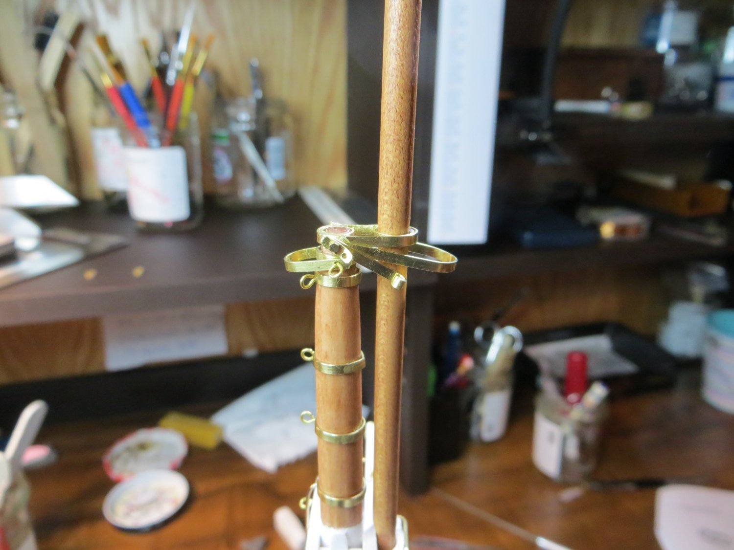
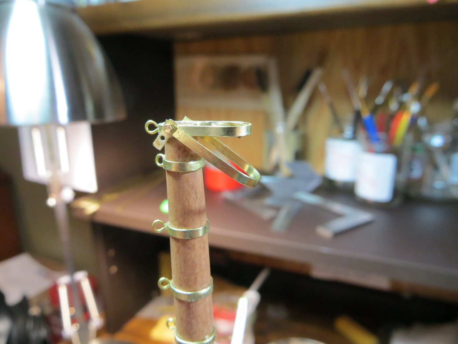
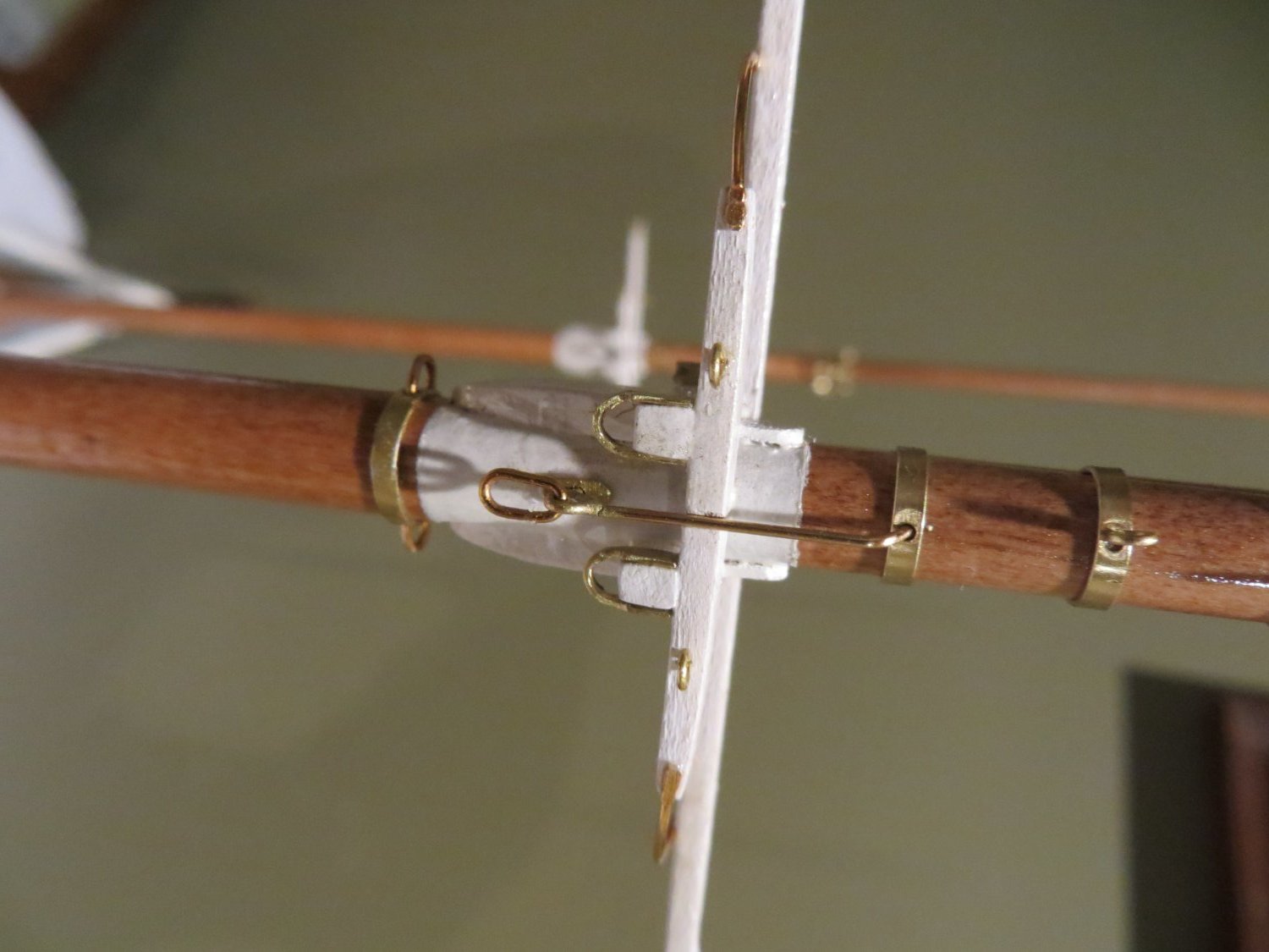
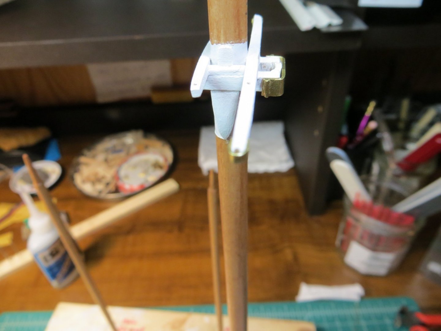
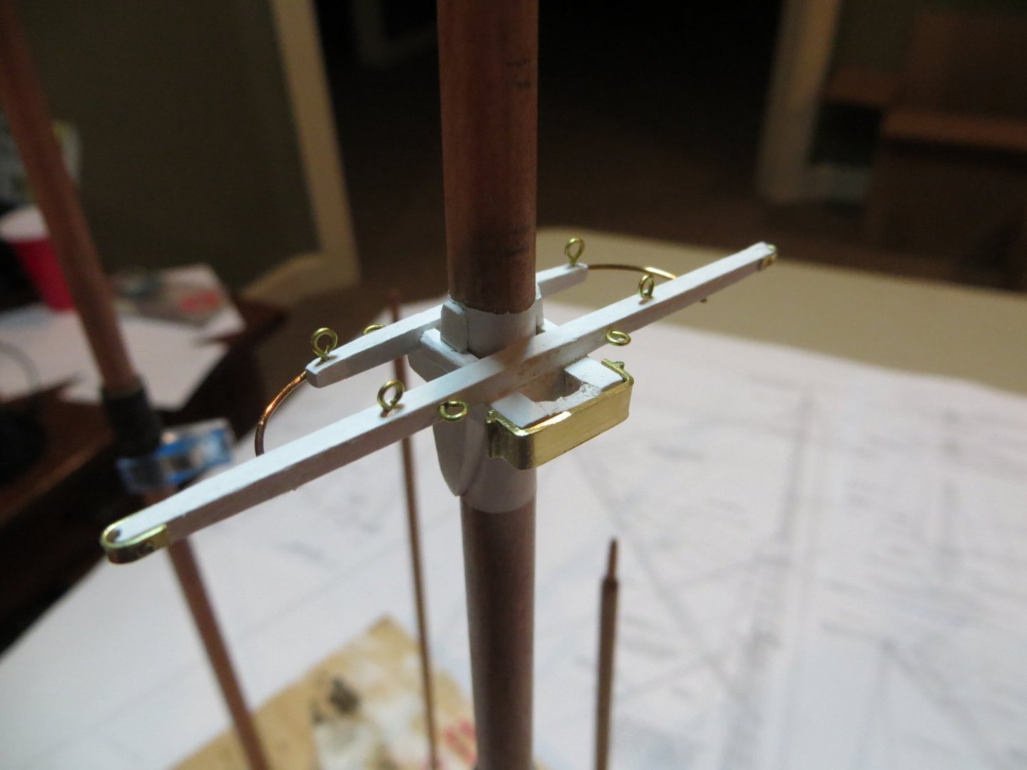
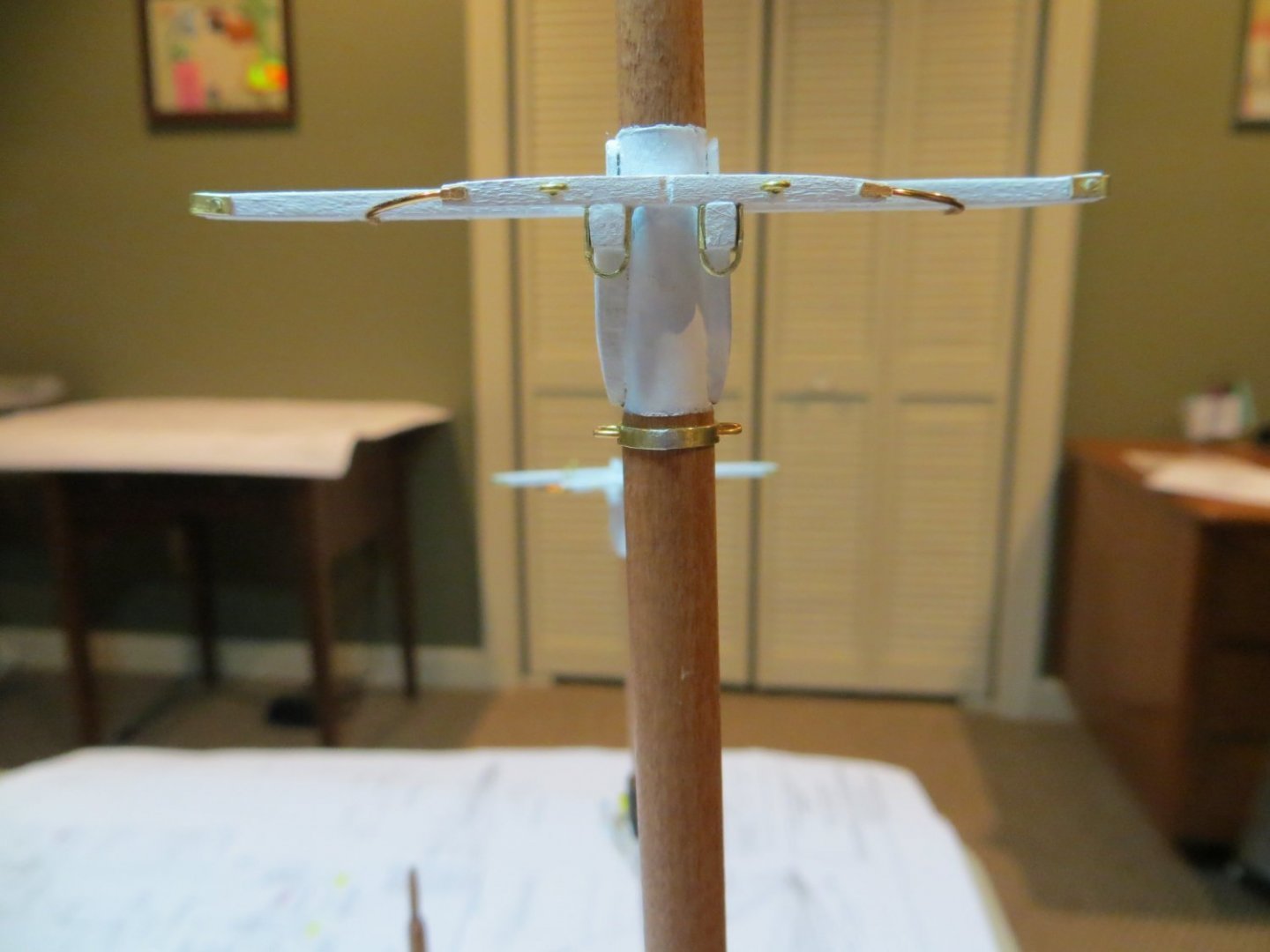
Originally posted Nov 17, 2021 Creating & Attaching Brass Hardware on Trestle Trees The following pieces are identical for items 1, 2 & 3 on the Fore & Main masts. I built them both simultaneously. Construction Steps 1. Iron Gate – this is a band of metal that goes around the fore end of the trestle trees to hold the topmast. I used a 1/8” wide brass strip, since these need to be larger than the supplied strip in the kit. I soldered a piece of brass rod on each side to simulate the hinge pins on the plans. I measured the length required and carefully bent the brass to fit across the trestle tree pieces. After installing the iron gates, I found that the top masts had too loose a fit for my liking. I inserted a very small piece of wood in the space between the iron gate and where the topmasts will sit. You can see this in pic #3 below. 2. Iron Clips – These are brass U-shaped pieces on the ends of the long spreaders that are used to run rigging through. Iron clips are made from 1/16” brass strip. The plans call for a pair of holes on each side of each clip for simulated bolts. I didn’t think I could fit 2, so I just drilled one hole in each end. Then I bent these into a U Shape and glued them in place. I drilled a very shallow hole into the trestle and inserted a piece of wire to simulate bolts. Don’t hardly sink these into the wood, because the wood is pretty narrow. 3. Spreader Rods – run from the aft face of the small spreader to the bottom of the long one. I marked the spot on each spreader where the wire needs to be connected. I used some .025” “Art Wire” for the rods. This stuff is easy to shape with your fingers. Cut to length and flatten the ends of the wire with pliers. Glue them in place. 4. Fairleads & Eyebolts – A Fairlead is a device with a hole in it that directs a rigging line and prevents it from snagging. I used eyebolts for the fairleads. There are also a number of eyebolts required. NOTE: I drilled all of these holes in the wooden pieces before assembling and painting them. a. Fairleads (Foremast) – 2 for the jib halliard facing forward on large spreader; 2 for peak halliard facing aft on small spreader b. Eyebolts (Foremast) – 2 for lifts on top of large spreader; 2 for lifts on top at the ends of the small spreader; 2 more underneath the forward ends of trestle trees for jumbo halliard blocks c. Fairleads (Main mast) – 2 eyebolts facing aft on the small spreader 5. Quarter Lift Shackles – 2 U shaped shackles are attached under the aft end of the trestle trees, only on the main mast. Use kit brass strip. The bottom part of the U that falls below the trestle trees needs to be filed down on each side to narrow the width. You are supposed to drill 2 holes at the top for fake bolts into the trees. But I could not figure out how to drill holes and insert rods in this narrow space without damaging anything! So, I simply CA glued them in place. Pic showing Quarter Lift Shackles & Futtock Shroud. In hindsight, I should have rigged the brass wires on the futtock now, when I could have worked off the ship. I did it just before attaching the lower shrouds and this was more difficult due to the other stuff that was in the way.
- 96 replies
-
- 2
-
-
- model shipways
- bluenose
- (and 1 more)
-
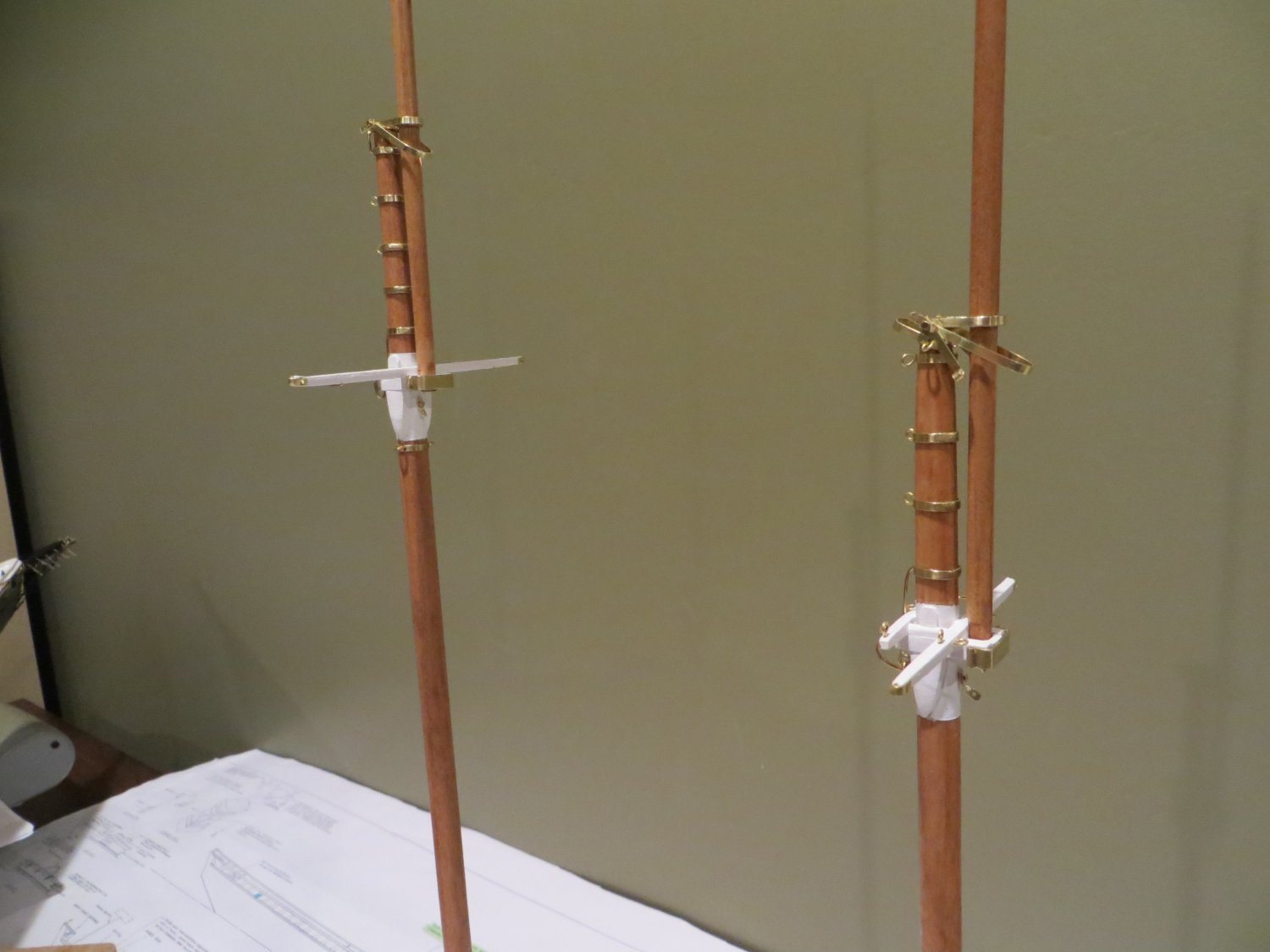
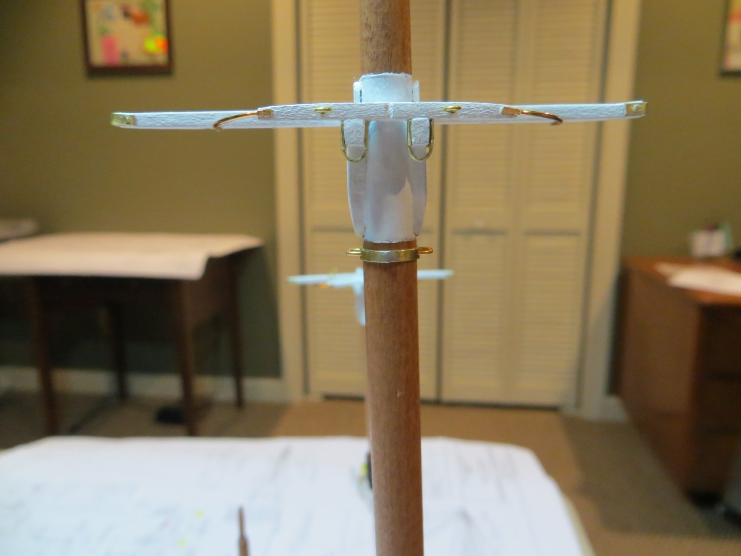
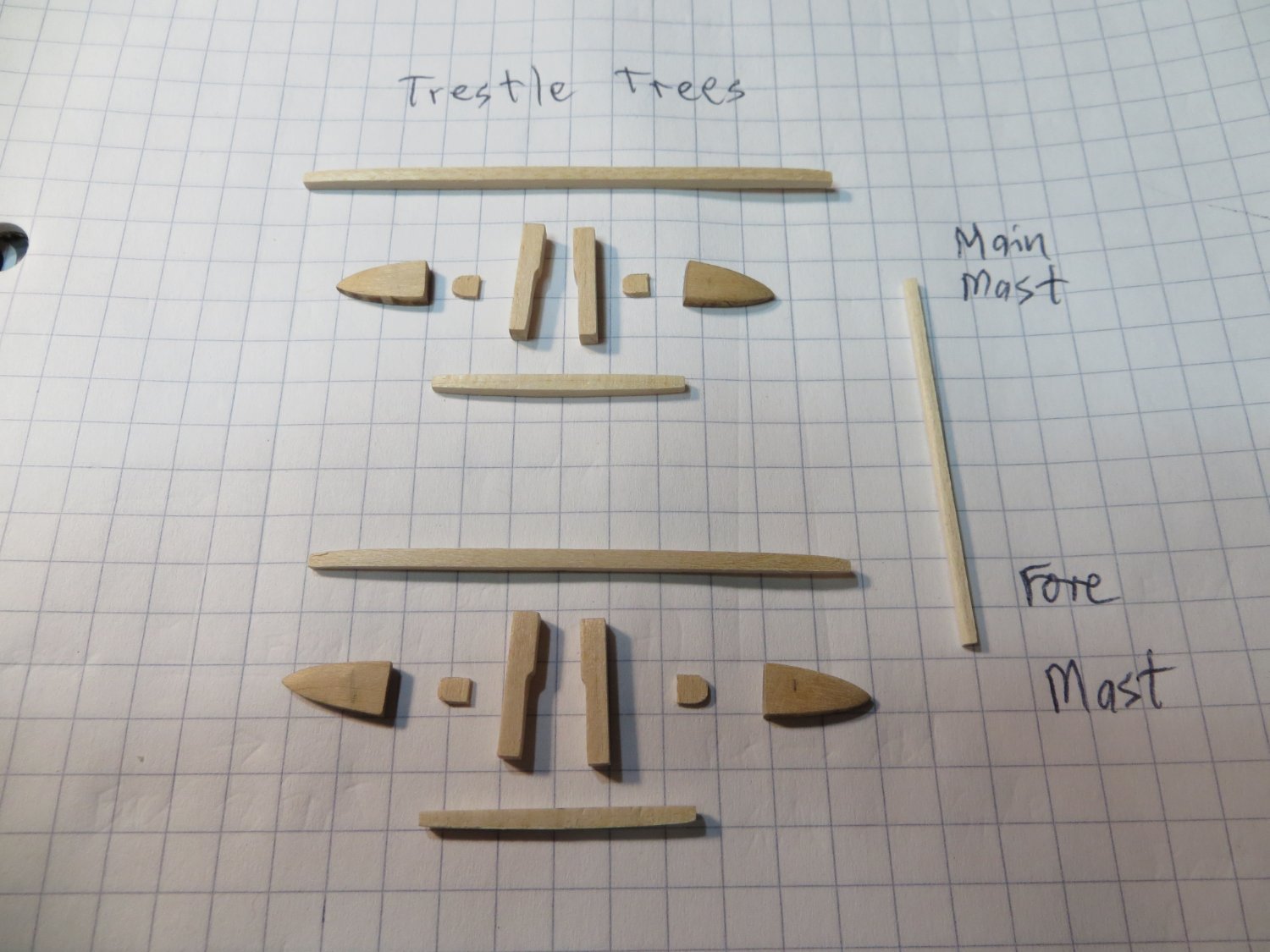
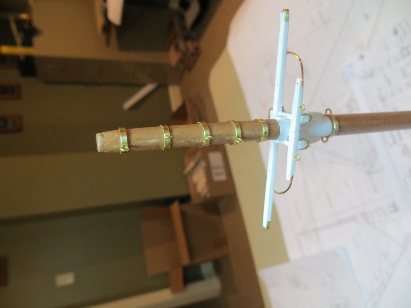
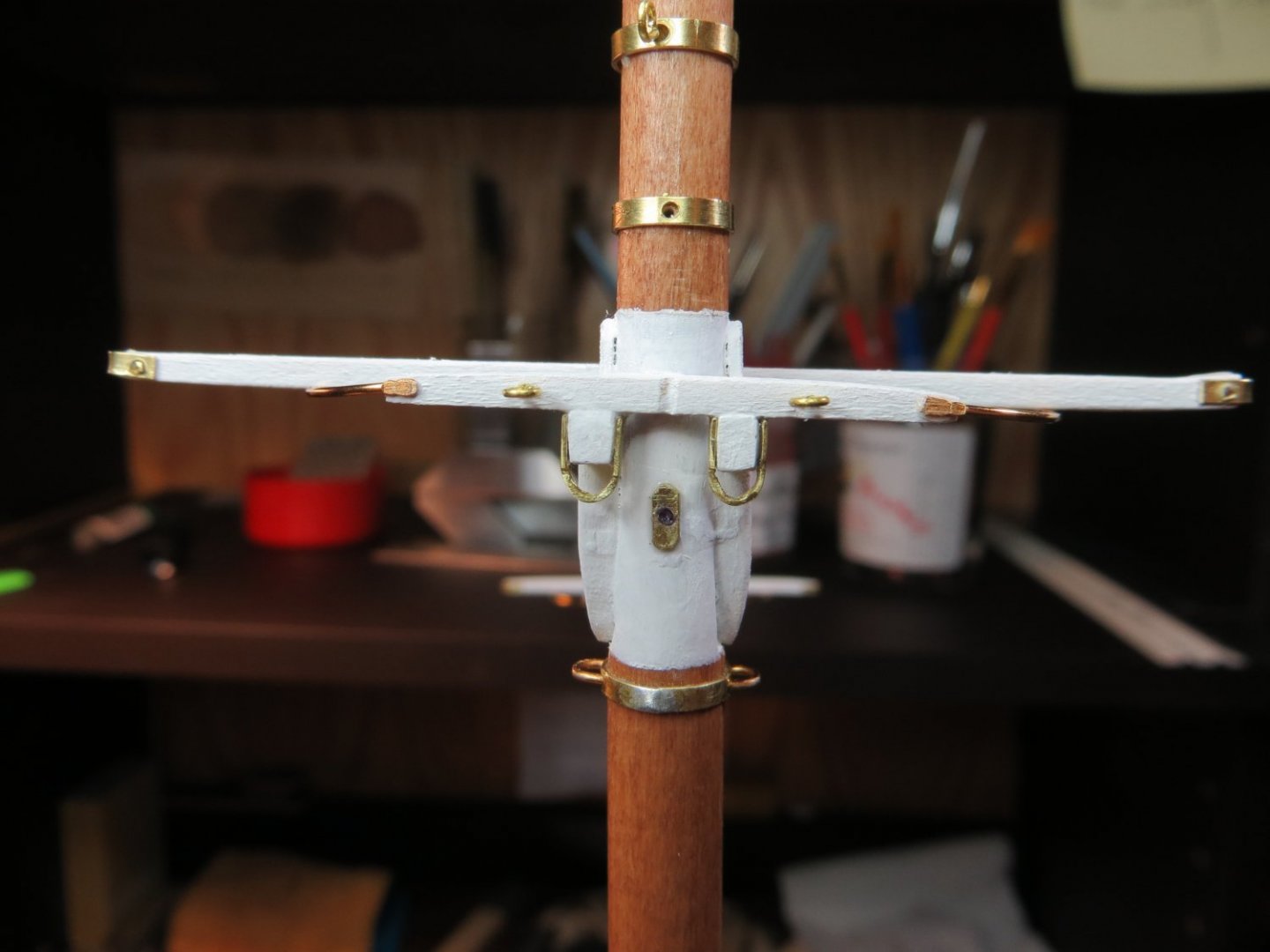
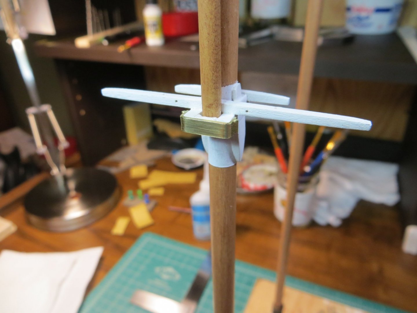
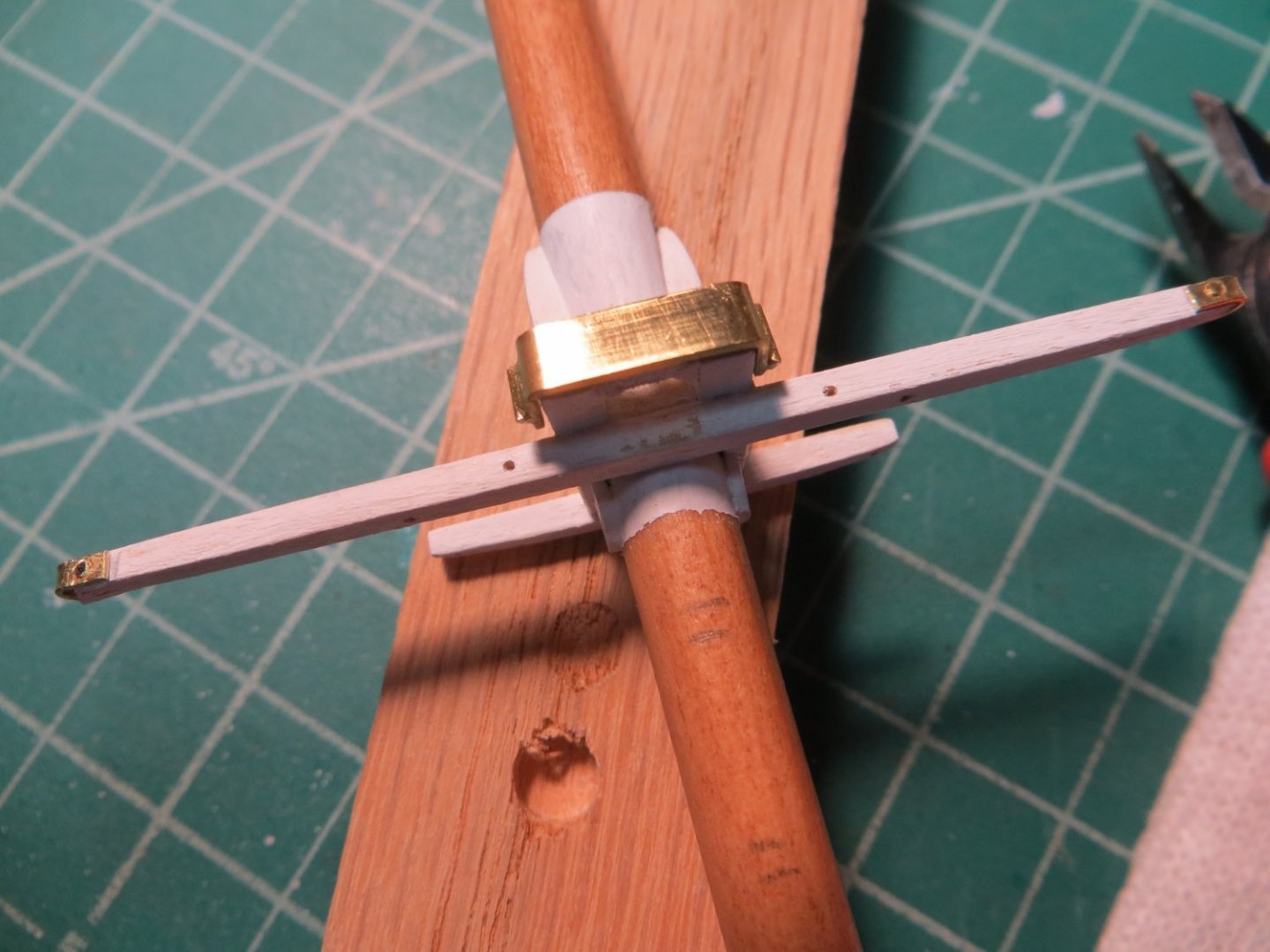
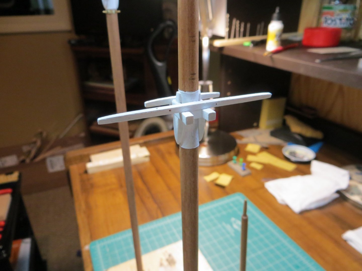
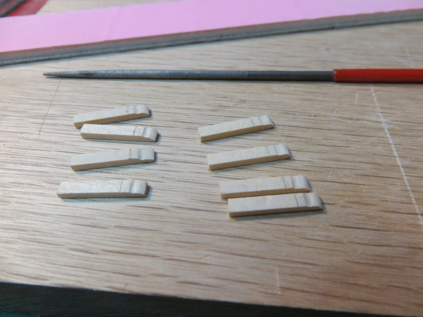
Originally posted Nov. 6, 2021 Constructing Trestle Trees Trestle Trees are built near the top of the lower masts. Their function is to hold the lower end of the top masts and contain the spreaders that keep certain rigging lines fixed in the correct places. Construction Steps 1. Before starting to build the trestle trees, I laid the mast on the plans and marked where all of the brass metal bands are supposed to go on both masts. This will be easier to do now without wood parts sticking out all over the place! 2. The first step I performed was to flatten the sides of the mast where the cheeks and trestle trees will go. Some builders attach the Futtock Shroud Band on the Main Mast first. I waited to ensure the band will be in the proper position and have the correct diameter around the mast. Mark the location on the masts where the dowel needs to be flattened and use a file to sand it down. Be very careful to get it flat and straight. The flat portions must be on the port and starboard side, and must run perfectly parallel with the hull, or the trestle trees won’t be straight. Getting stuff like this straight has been one of my most challenging tasks. If anybody has a secret technique for accomplishing this, I would love to hear it (for future builds)!! 3. So, next step, I attached The Futtock Shroud Band which sits right below the cheeks that hold up the trestle tree. a. Make the band from kit supplied 1/16” brass strip. b. Close the band by soldering. c. Drill a pair of holes in both the P/S sides of the band. Slip the band onto the mast and CA glue the band in place. d. Deepen the holes into the mast with #64 pin vise bit and insert a wire “staple” into the holes to simulate the shackle-like fitting that belongs here. 4. Prepare the following pieces from strip wood. Make 2 sets, one for each mast. The wood parts are the same except for the size of the spreaders. a. Cheeks – provided as laser cut pieces. Sand to clean them up and taper the bottom point. b. Bolsters – 1/16” square strip wood. The top outside corners need to be rounded off c. Slabs – 1/32” thick sheet wood. d. Trestle Trees – 1/8” square strip wood. File them down to be narrower around mast and toward aft. Before installation, drill the required holes in the spreaders. Size these for eyebolts for the fore mast holes. e. Spreaders – 3/32” square strip wood. The spreaders are tapered from the center to the ends. The larger spreader is tapered on the fore side, by 1/32″. The shorter spreader is tapered on the aft end by 1/32″. Both are tapered on the bottom by 1/32″. The lengths for both spreaders are longer for the main mast. Check the plans. Carve a notch at the center aft position in both small spreaders. This is used for the crane. f. Cross Blocks – This piece fills the space between the trestle trees, fore & aft sides, seated under the spreaders. Therefore use 1/8” square. All pieces ready to assemble: 5. Assembling all the wood pieces a. Glue on the cheeks first, then the trestle trees. The longer/wider ends of the trestle trees need to face FORWARD. Fit the cross blocks in next between the trees. b. Glue on the spreaders next. The longer ones need to face FORWARD. c. Finally, glue the slabs on top of the bolsters. d. Paint everything white Completed Main Mast Trestle Tree: Completed Fore Mast Trestle Tree:


- 96 replies
-
- 3
-
-
- model shipways
- bluenose
- (and 1 more)
-
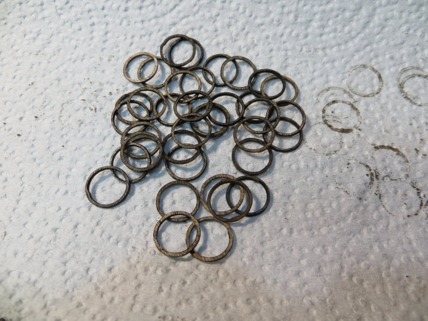
Originally posted Nov. 6, 2021 Mast Coats & Mast Hoops There are actually two more construction steps left to complete the creation of the bottom portion of the lower masts. Mast Coats cover the base of the mast at the deck. Mast Hoops are used to attach the sails to the mast. IMPORTANT NOTE: the mast hoops have to be slipped onto the masts after the lower parts are finished, but before trestle trees and the metal bands are installed. Mast Coats 1. I intentionally made the drilled out ½” dowel rod long enough to make the pin saddle and boom rest with enough left to make two mast coats. 2. I placed this piece horizontally in my small vise and sanded the end down to form a narrow collar. I then rounded off the top edge before cutting it off the dowel at the proper length to form the mast coat. Next, I sanded some more to soften the edge where the collar becomes the base. I repeated the process to make a second one for the other mast coat. 3. I test fit them on the bottom of each mast. A little clean-up was needed on the inside before I painted them with a couple of coats of white paint. I’m happy with the way they turned out! Mast Hoops 1. The mast hoops are provided as laser cut parts in the kit. They are very thin and delicate, so you need to handle them with care. 2. The biggest pain of this operation was cutting them loose from the sheet. I also dislike the process of removing the laser char. This stuff gets all over!! To make the process a little easier, I used the following technique. 3. Remove the parts from the sheet, but do not remove the centers. I stacked a bunch of them together and placed them in a clamp so they looked like a single cylinder. Then I used a sanding stick to sand the outside of the hoops. 4. After the outsides are sanded, remove the inner circular pieces. I held about 4 or 5 at a time between my fingers and used a slice off a sanding stick to clean the char off the insides. A tedious process. 5. When they were done, I strung them on a wire and dipped them in my Minwax Dark Walnut stain. I used the darker stain to provide some contrast with the cherry-stained masts. This is the same color I used on the deck structures. Here is a batch of prepared mast hoops: Now the lower portion of the lower masts are complete!


- 96 replies
-
- 1
-
-
- model shipways
- bluenose
- (and 1 more)
-
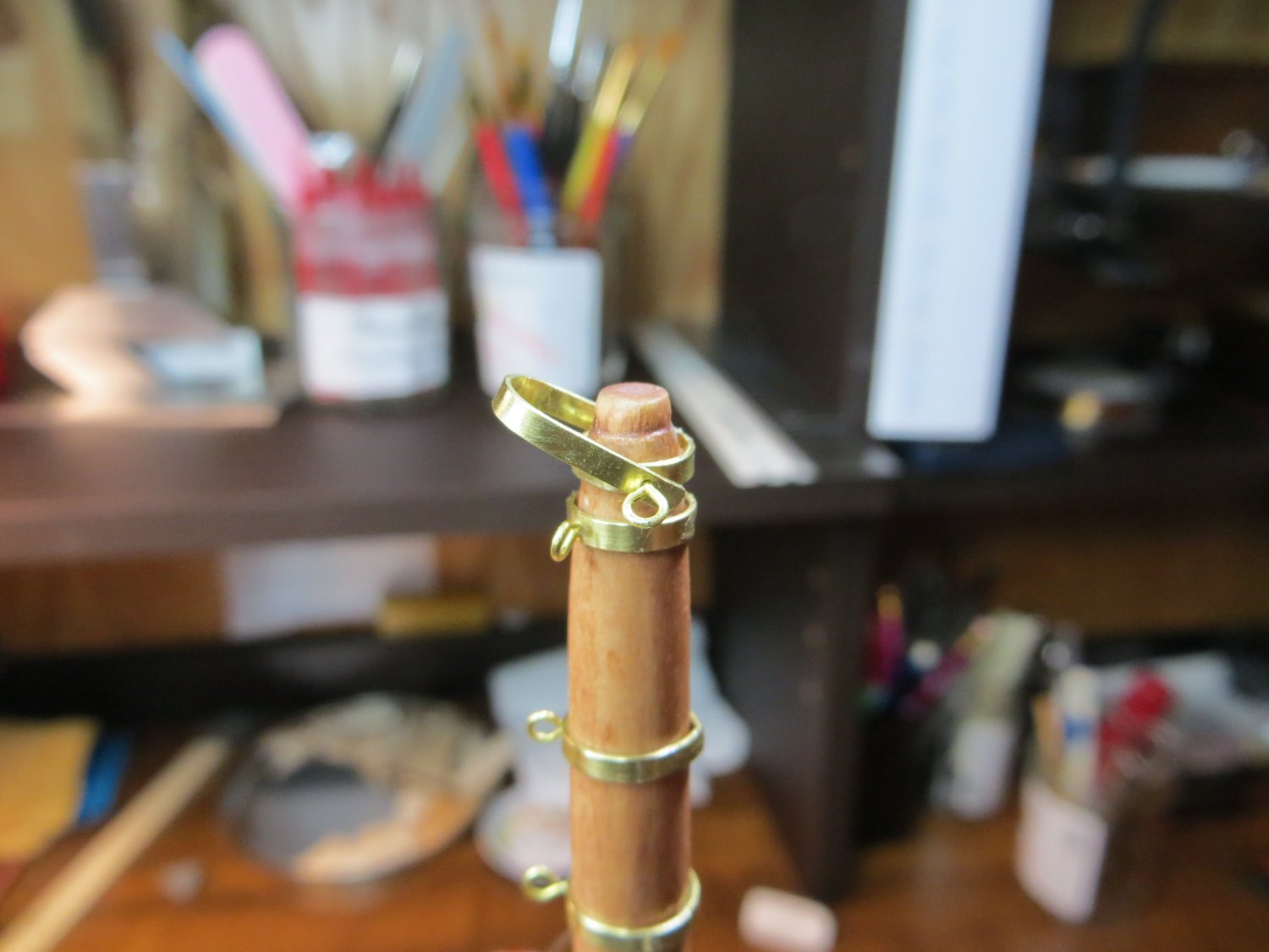
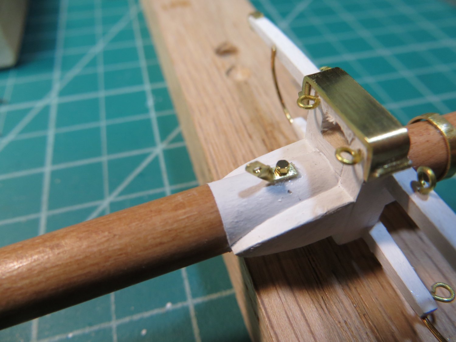
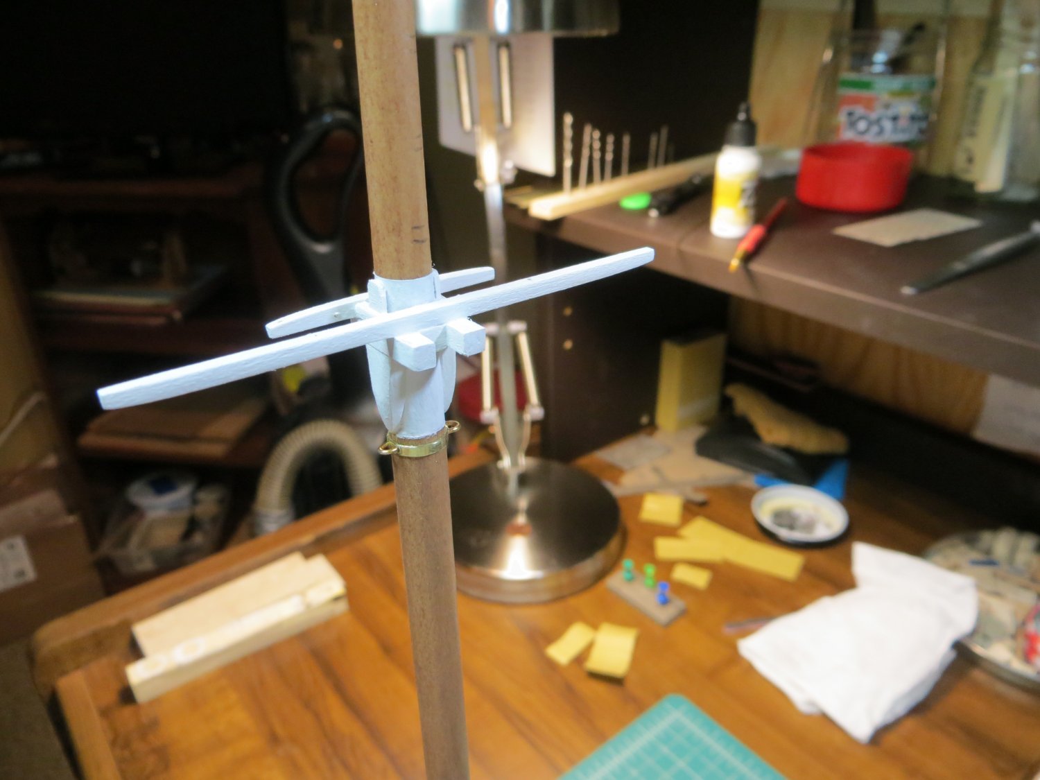
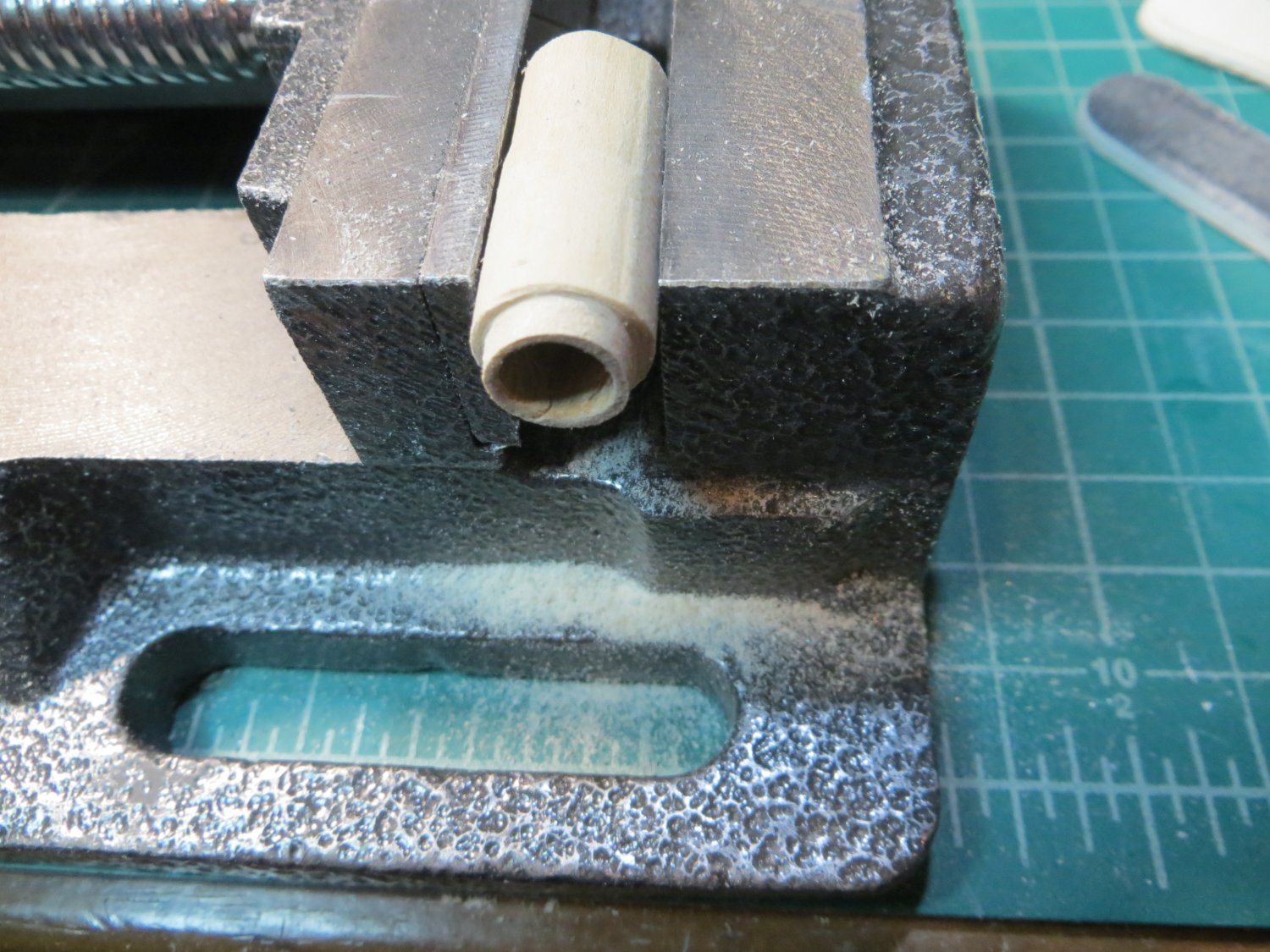
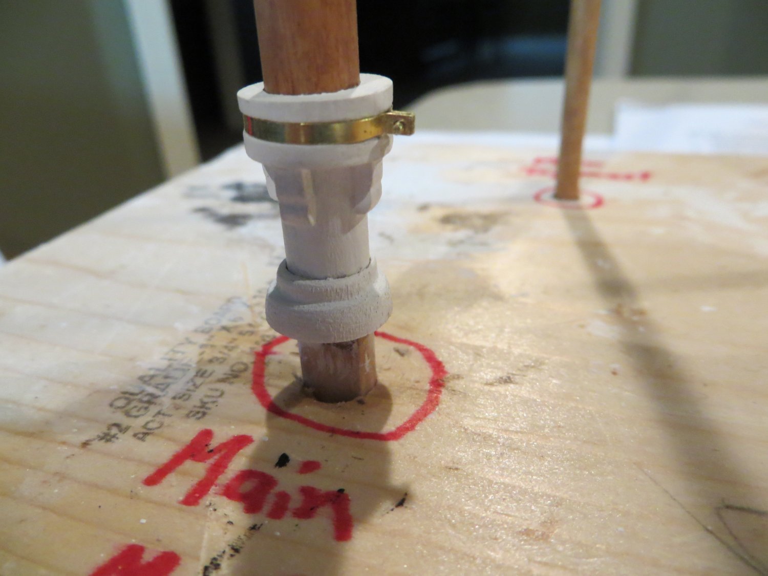
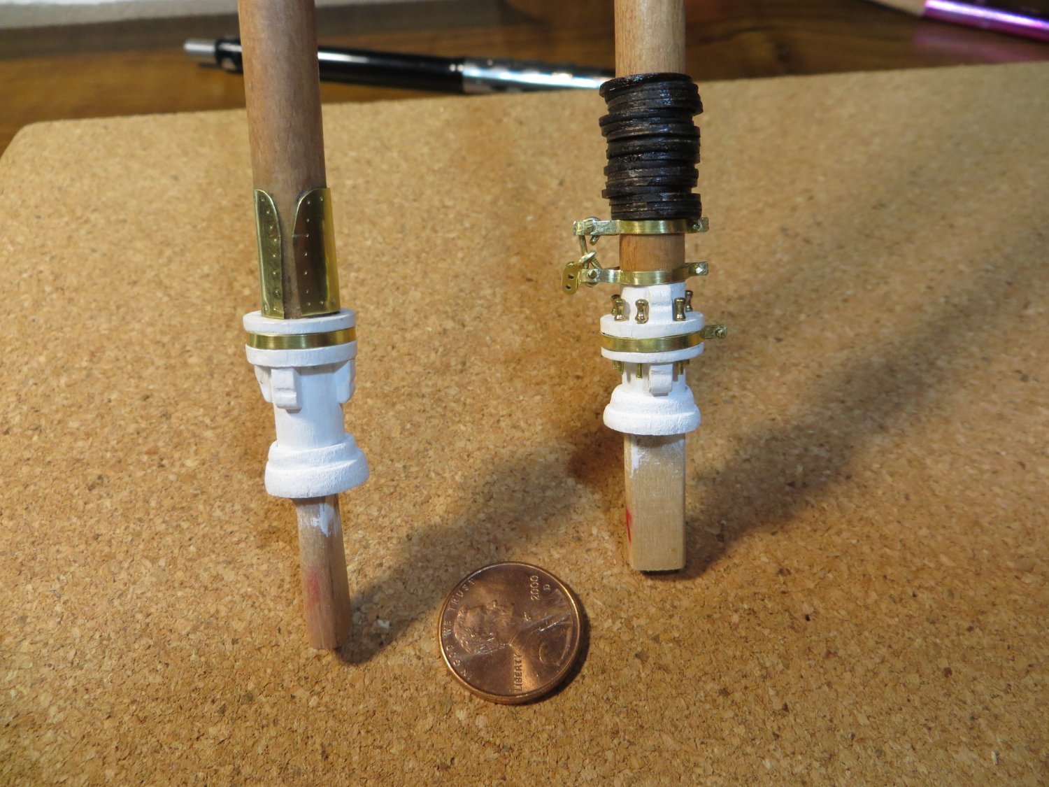
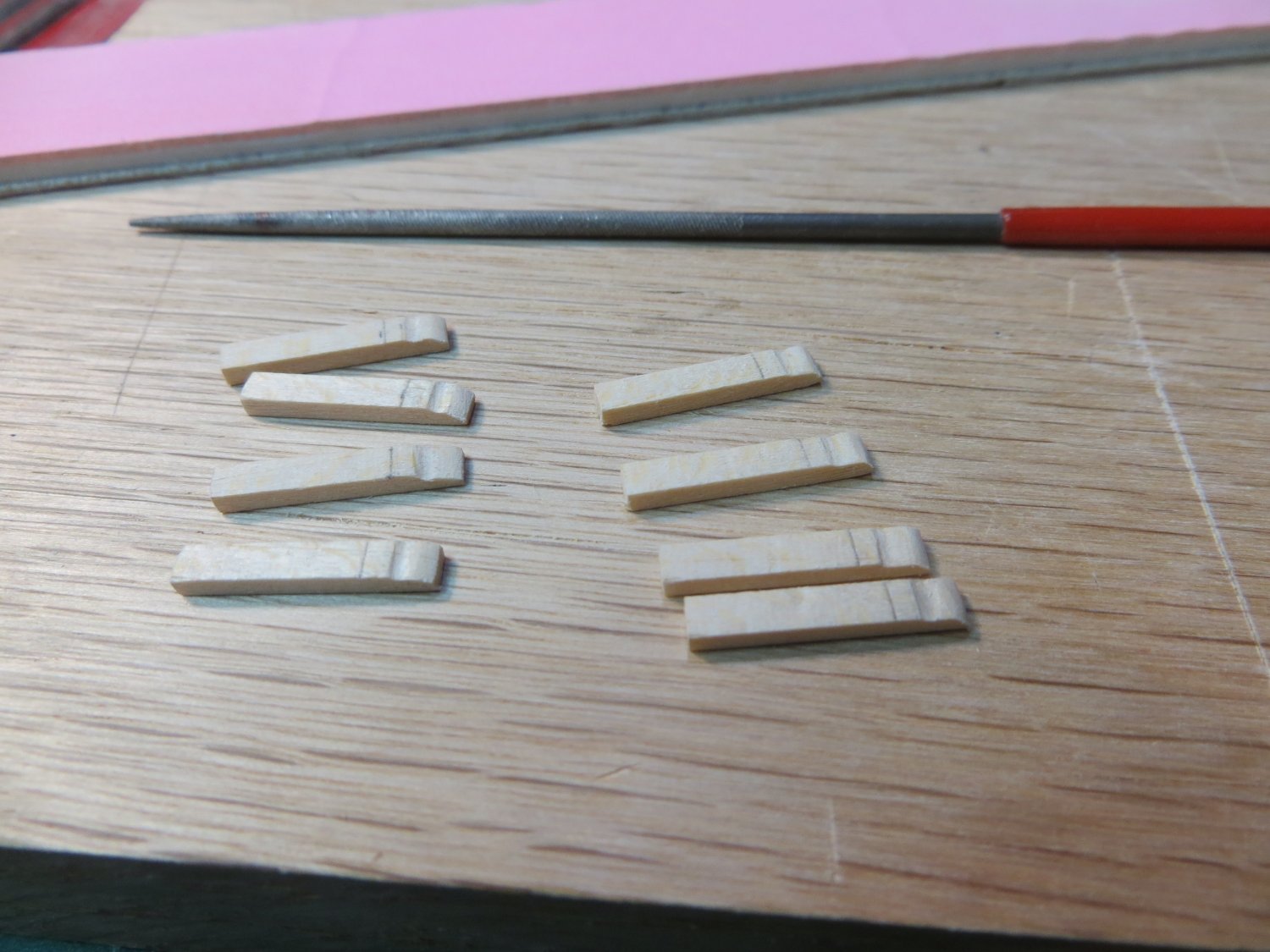
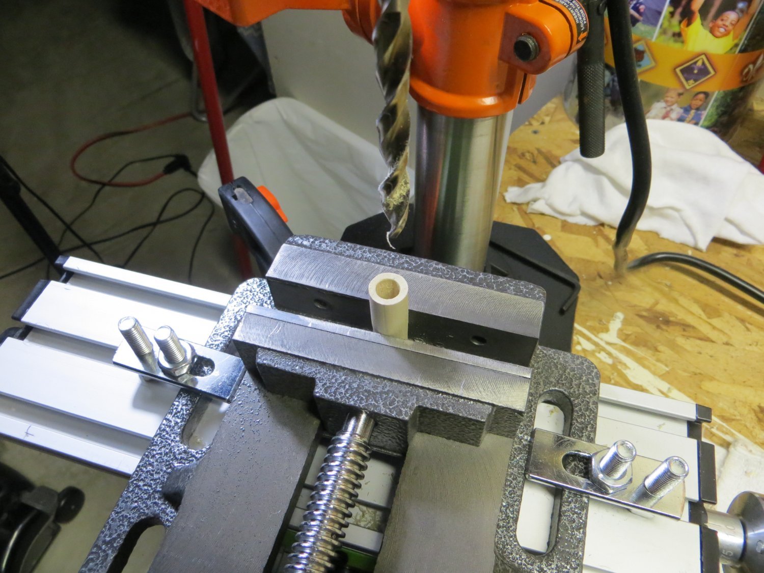
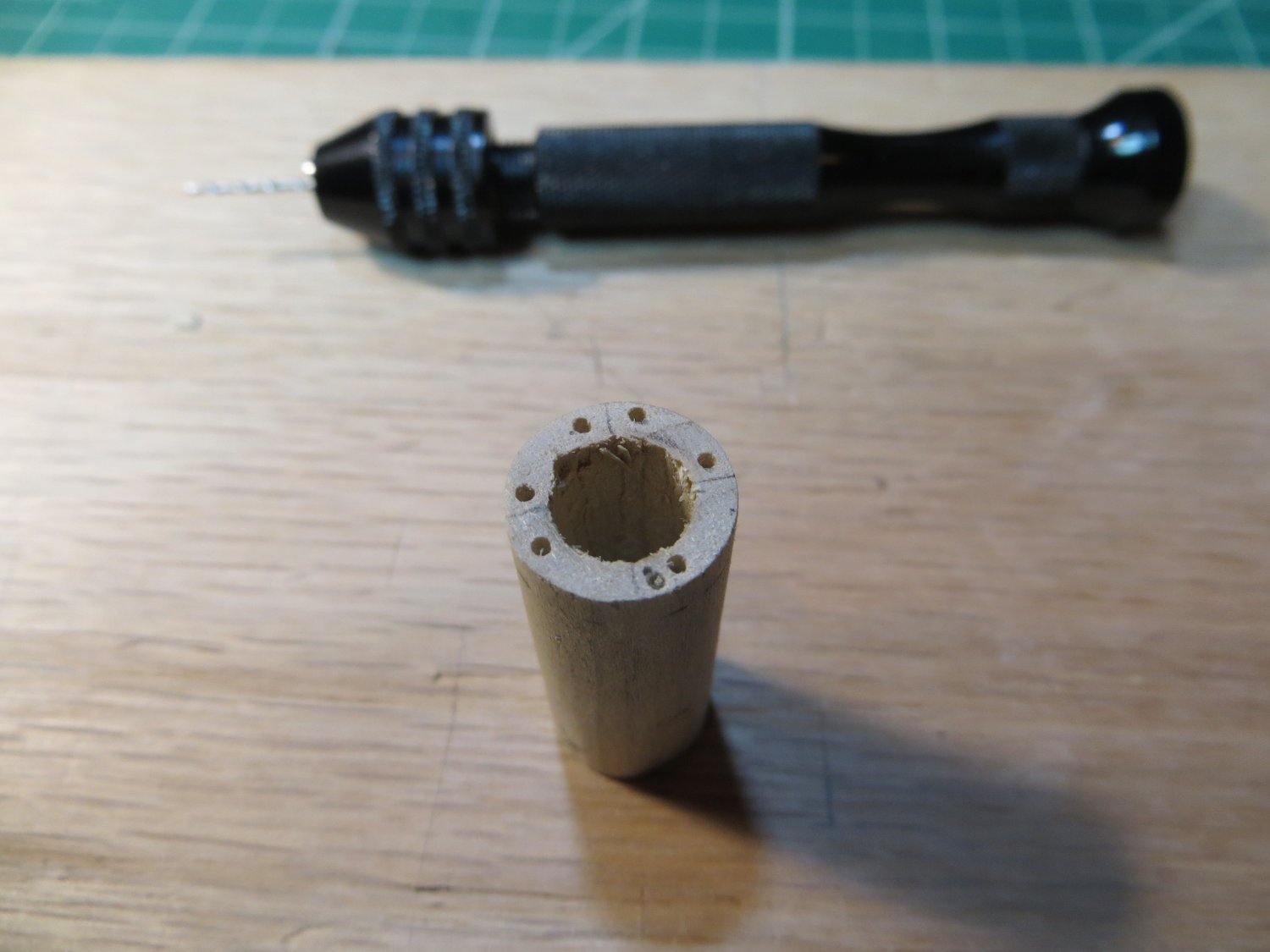
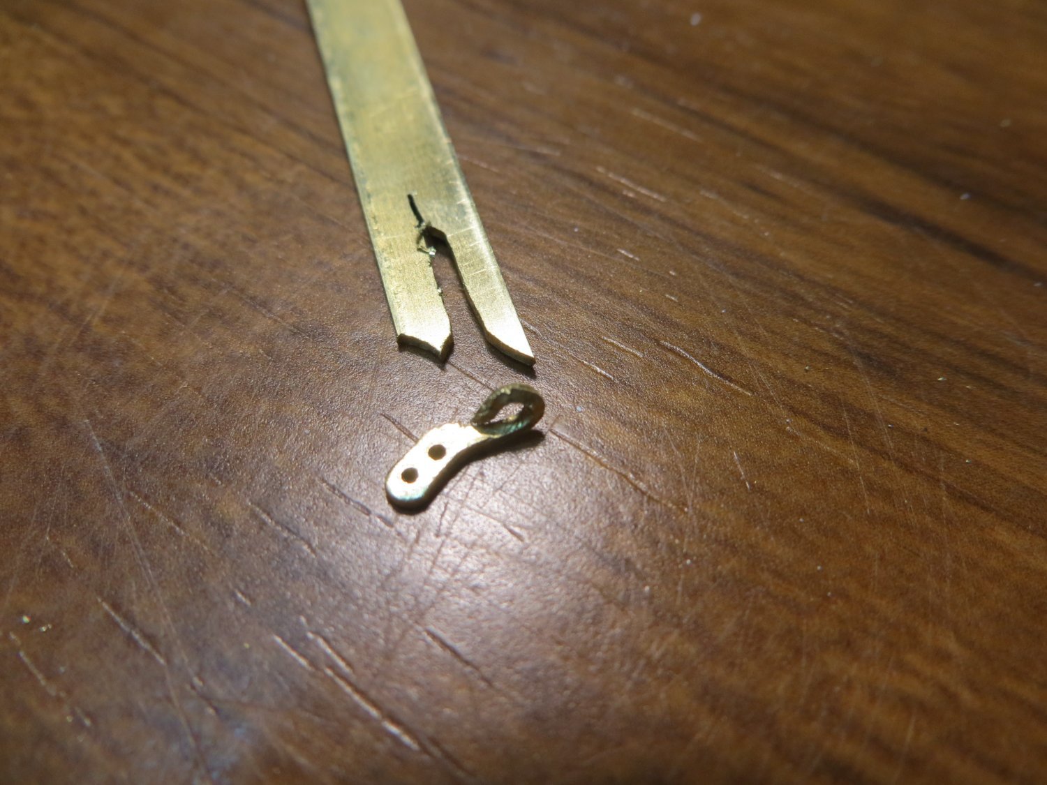
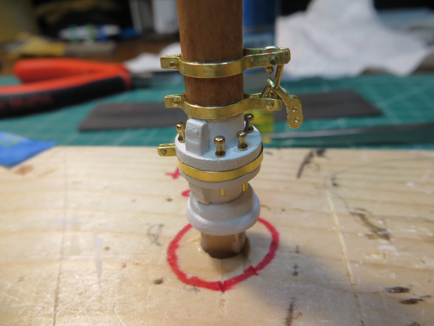
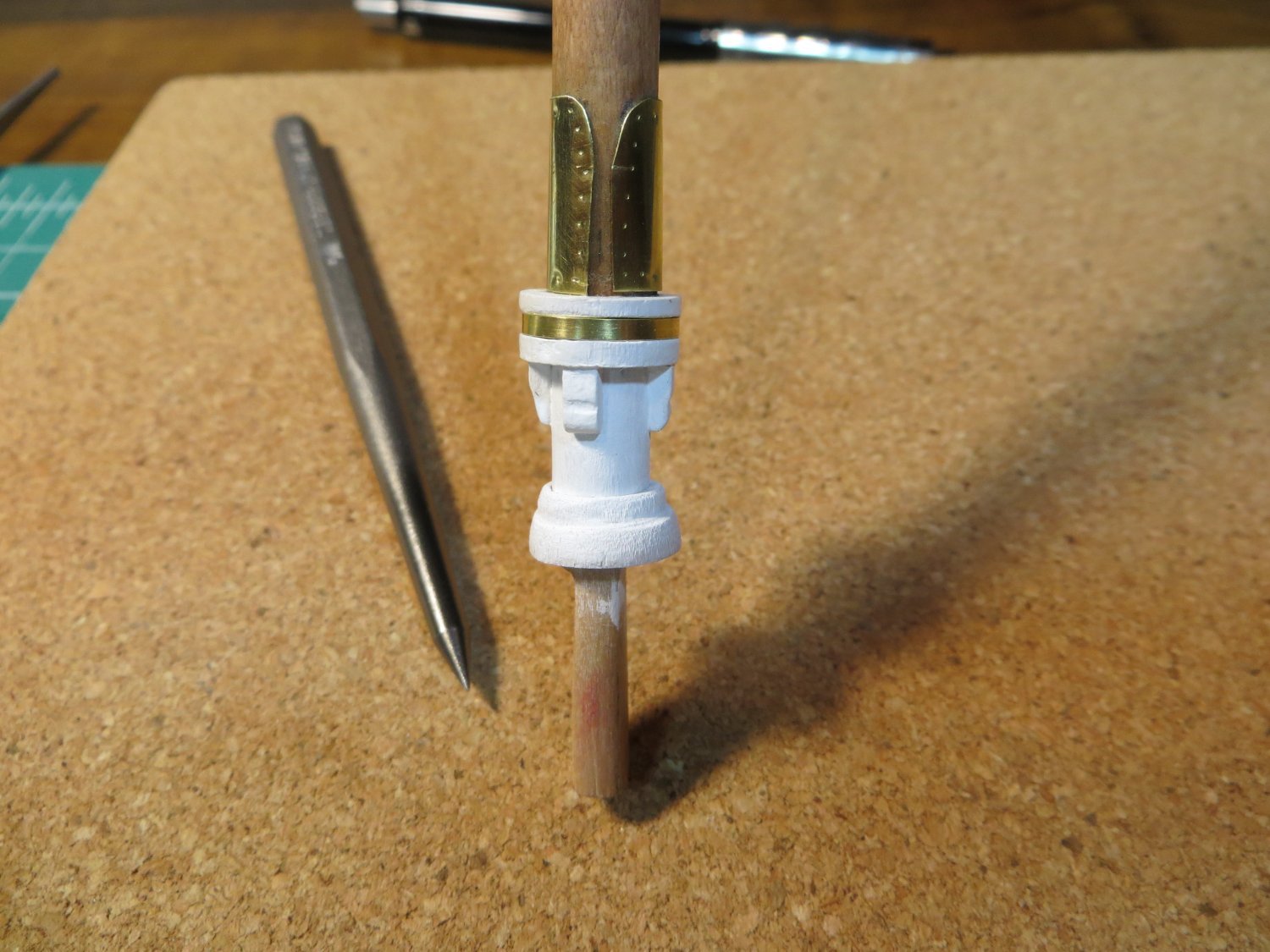
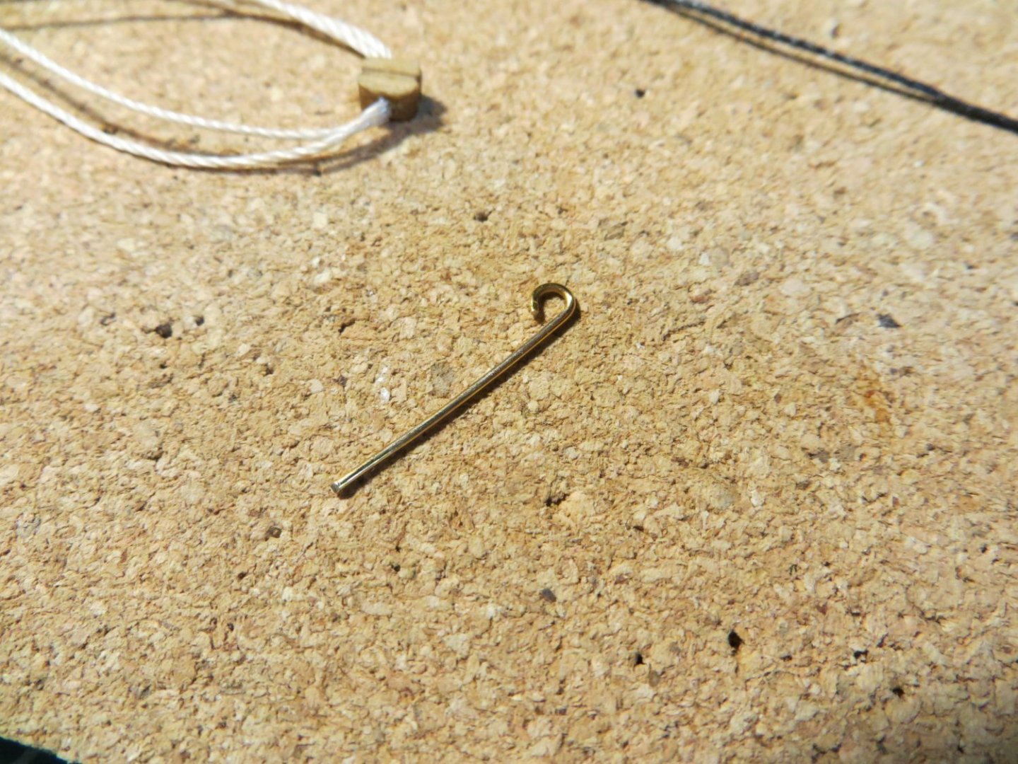
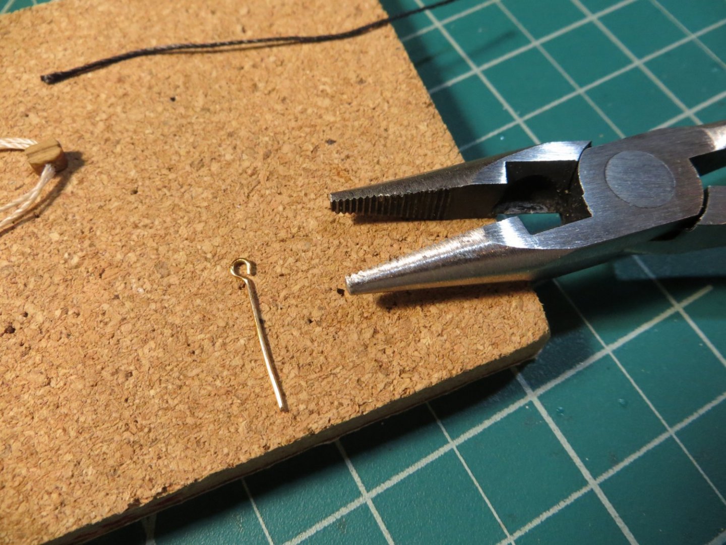
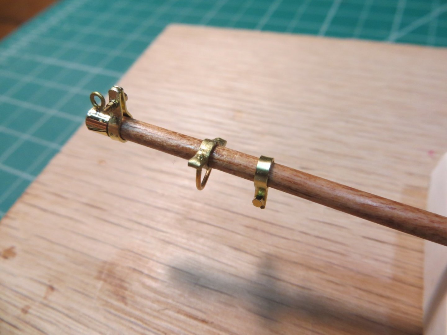
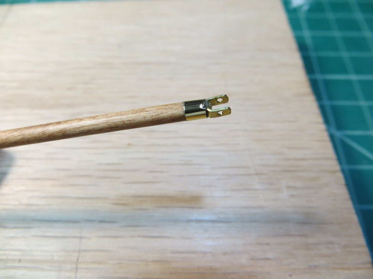
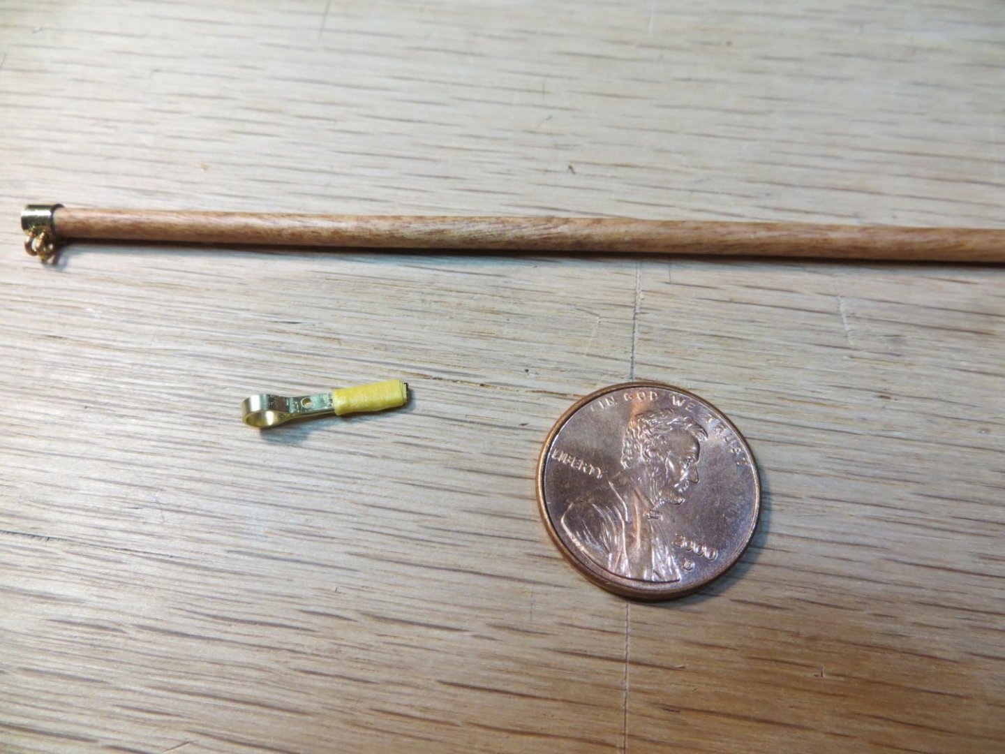
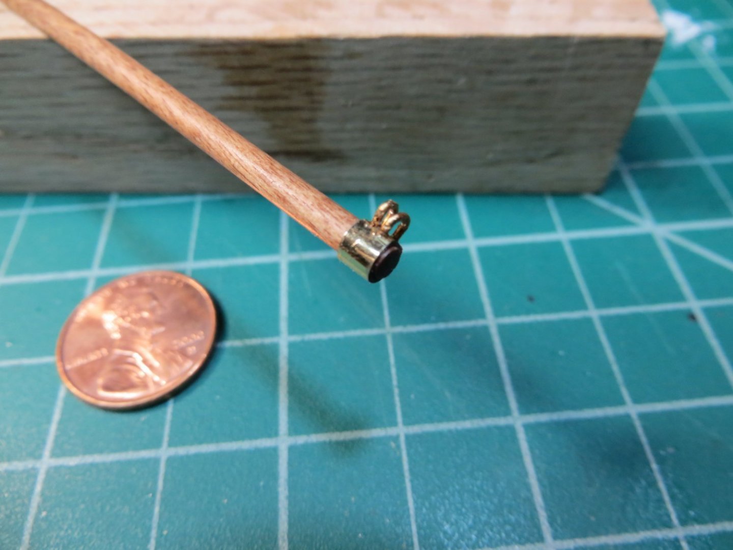
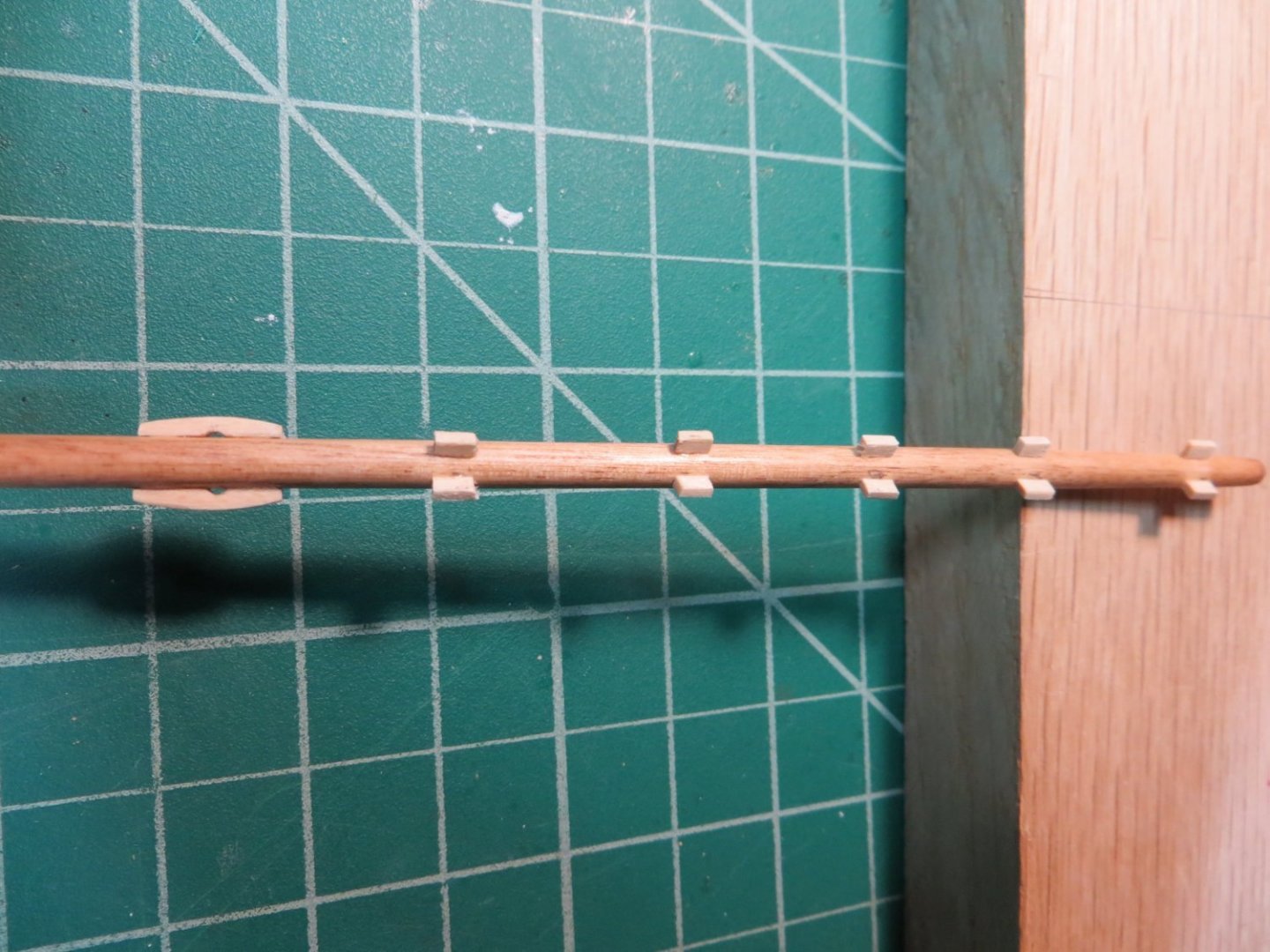
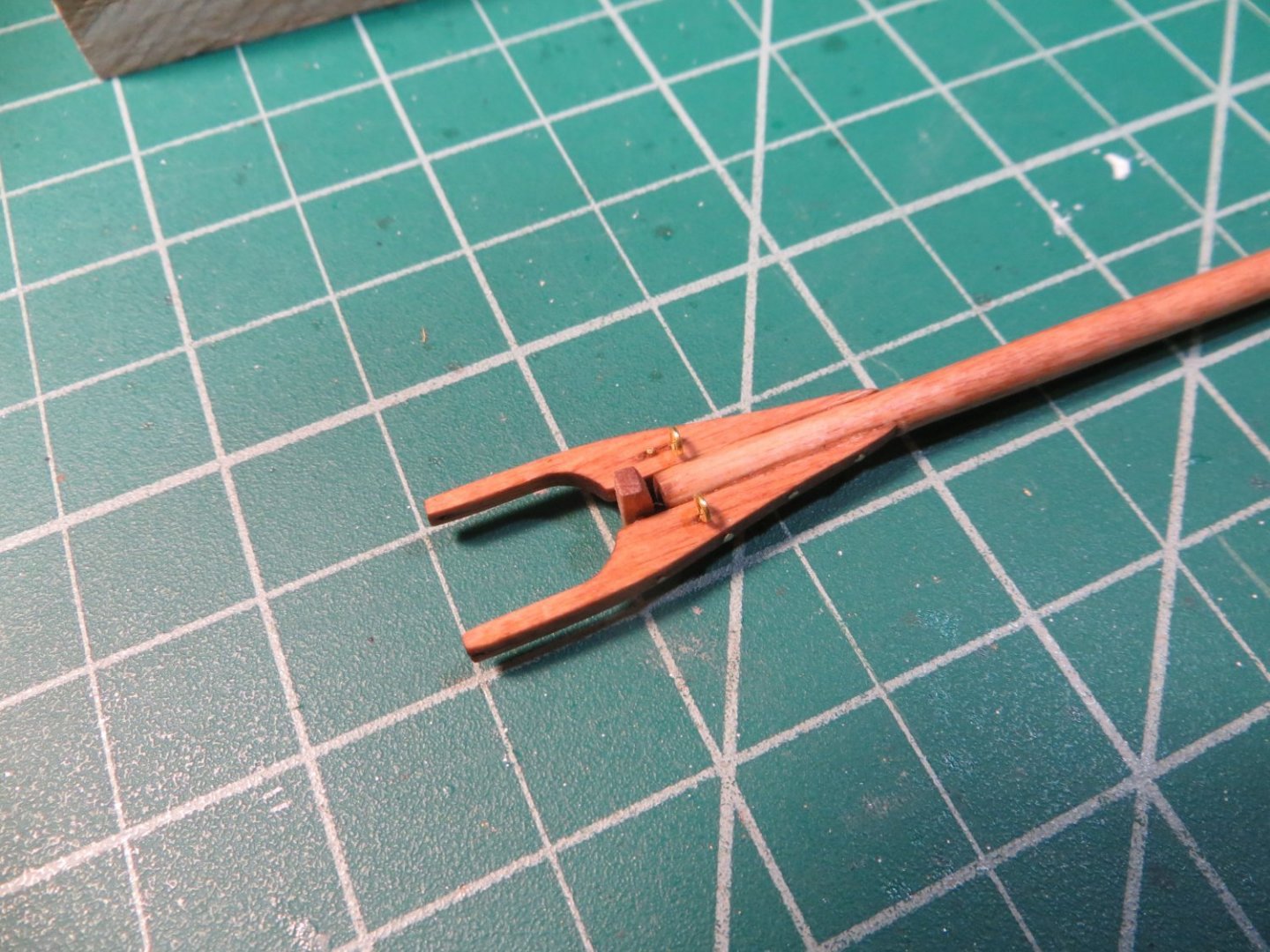
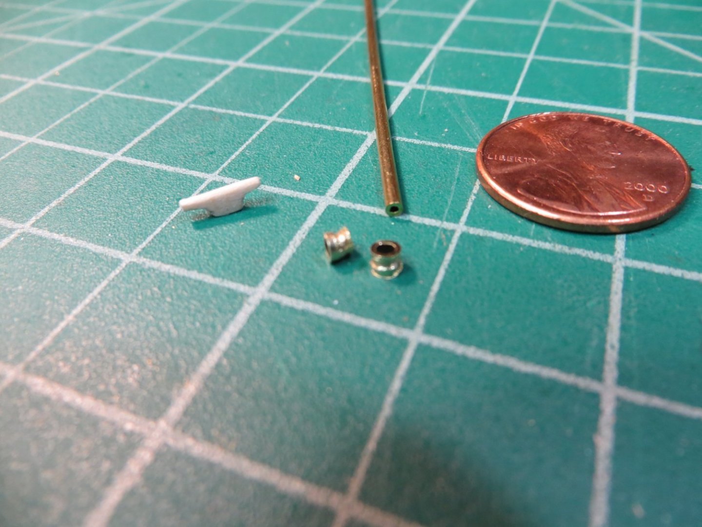
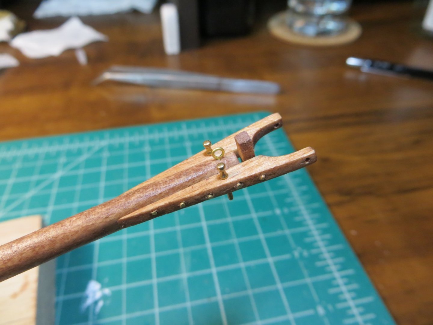
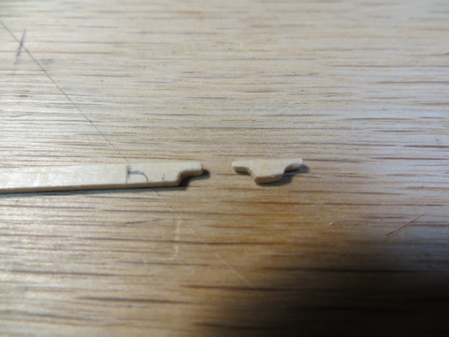
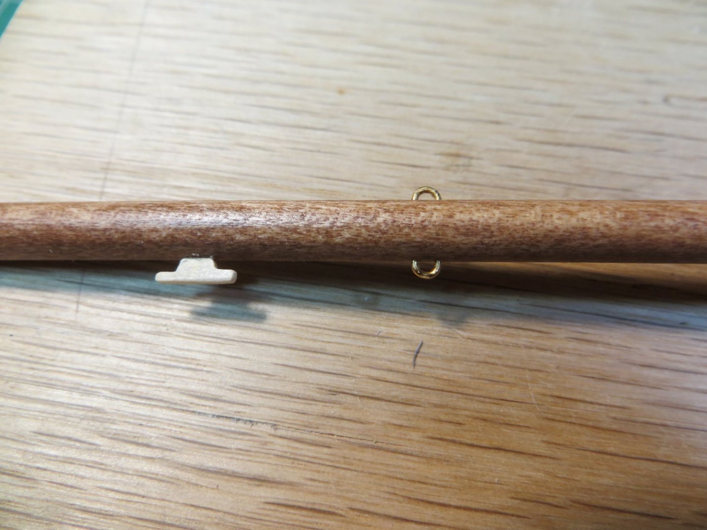
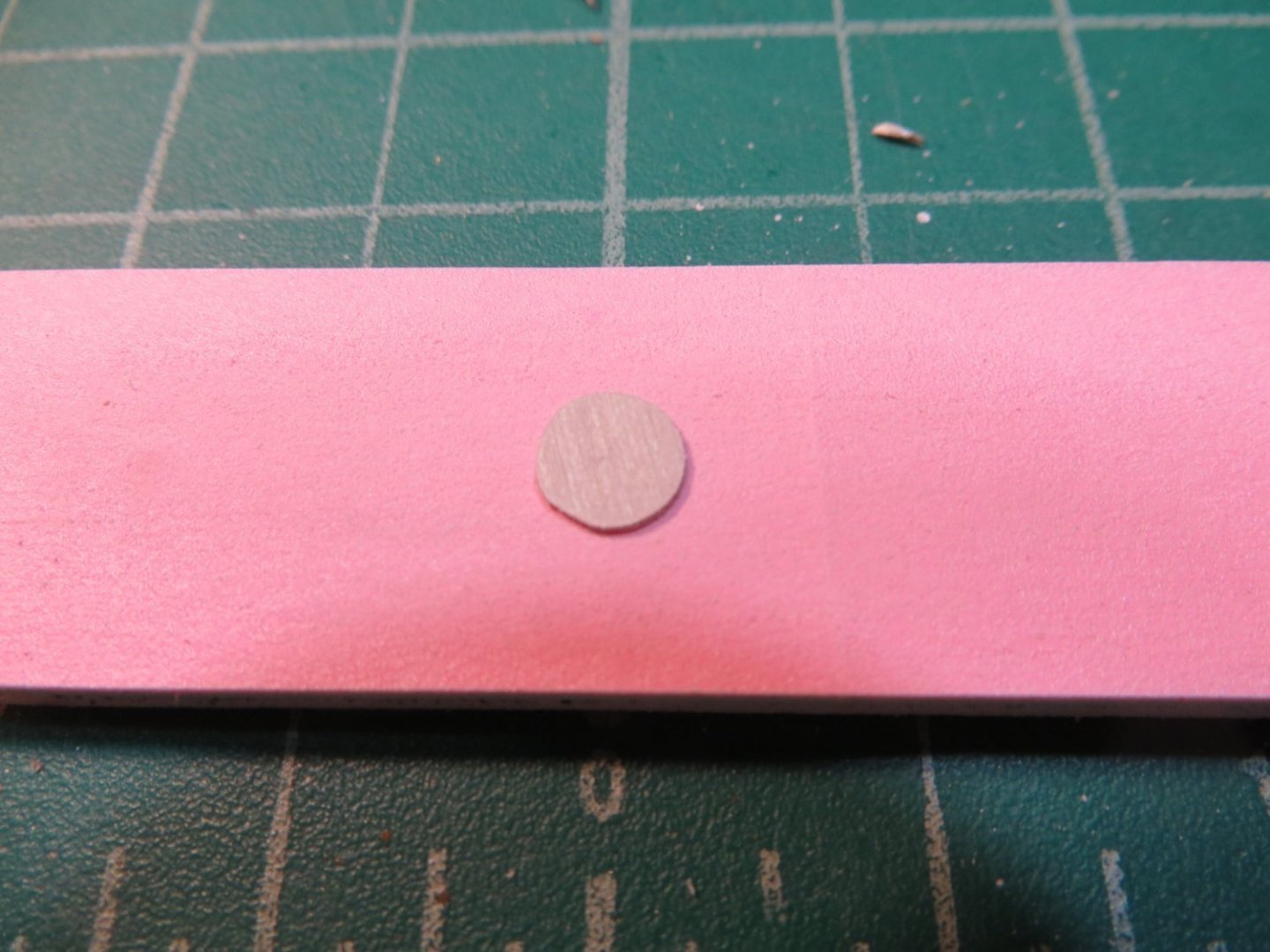
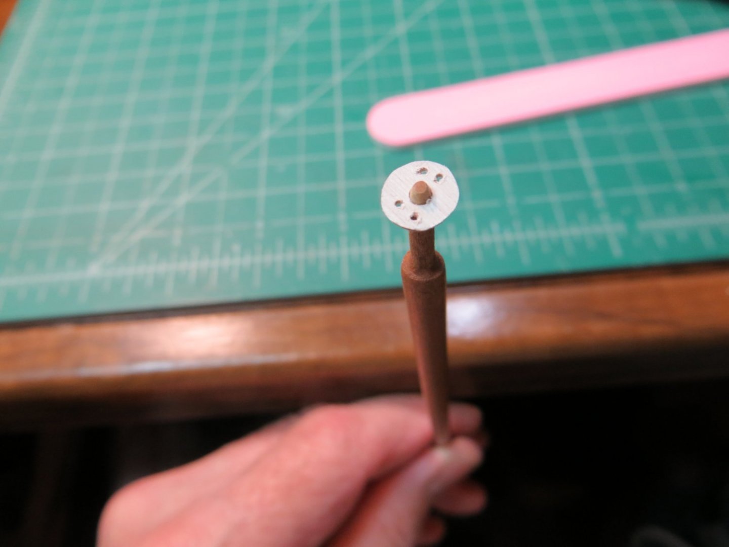
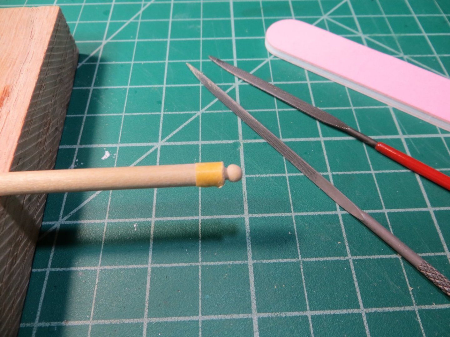
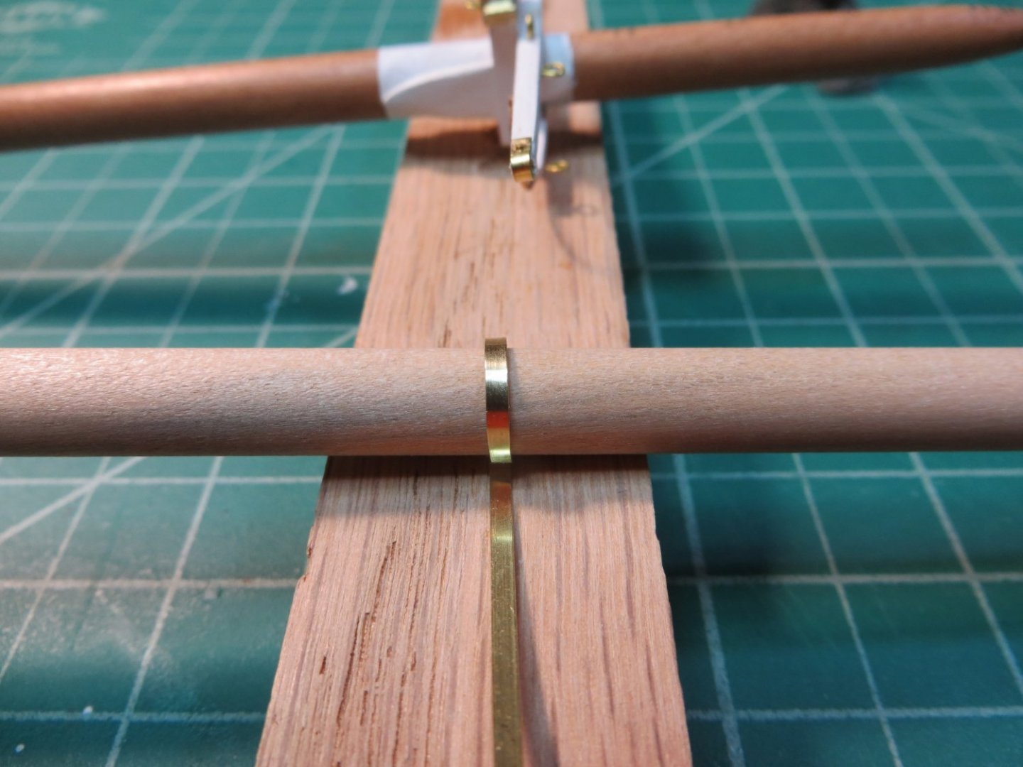
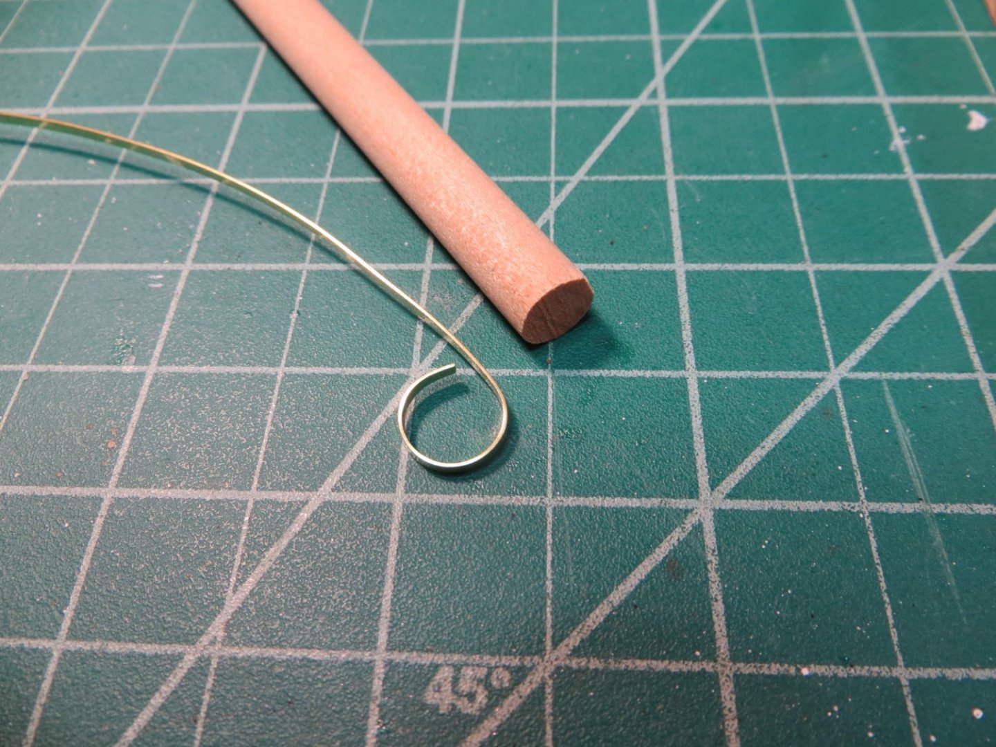
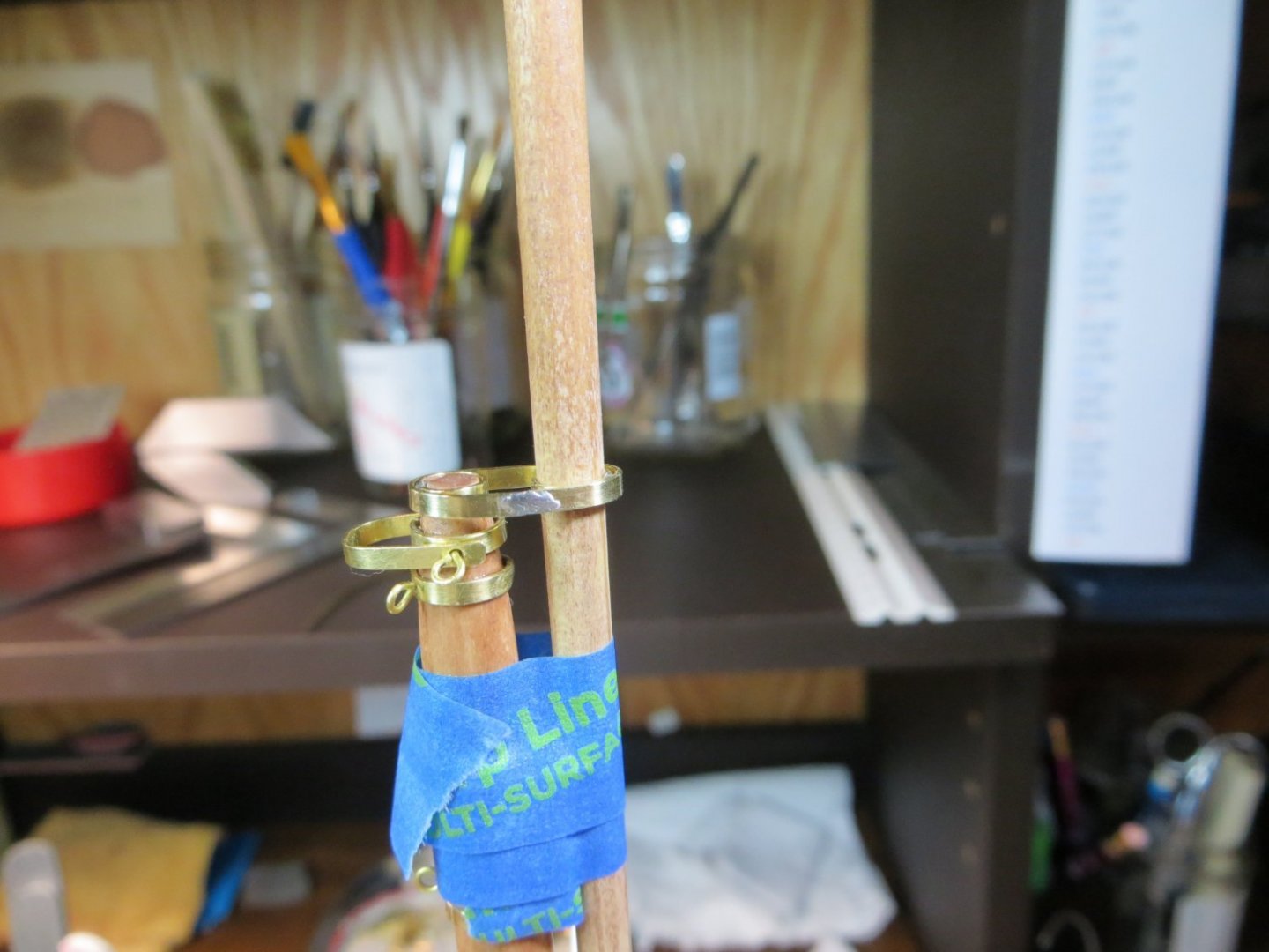
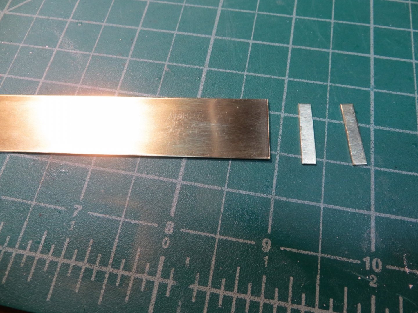
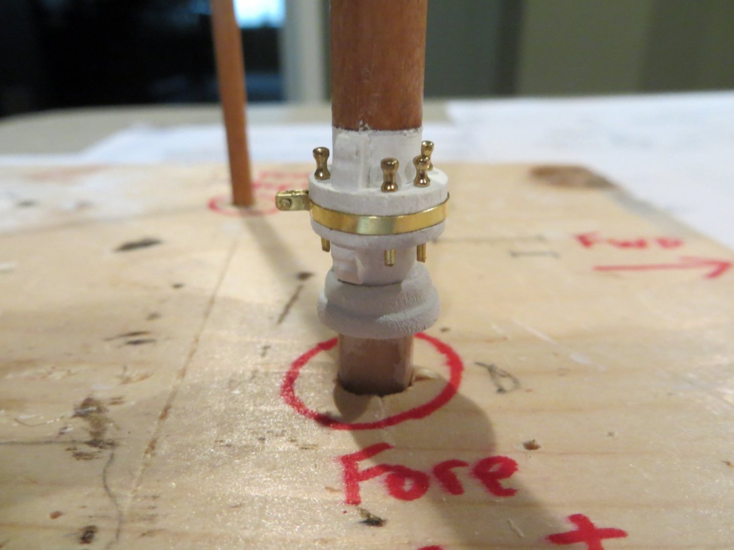
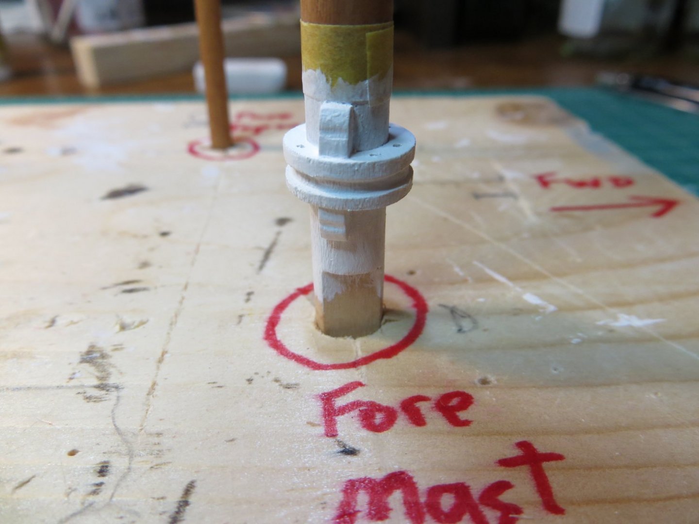
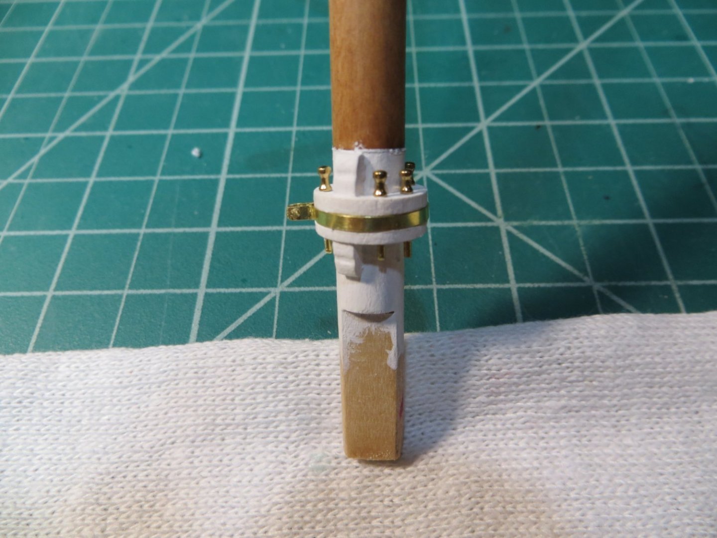
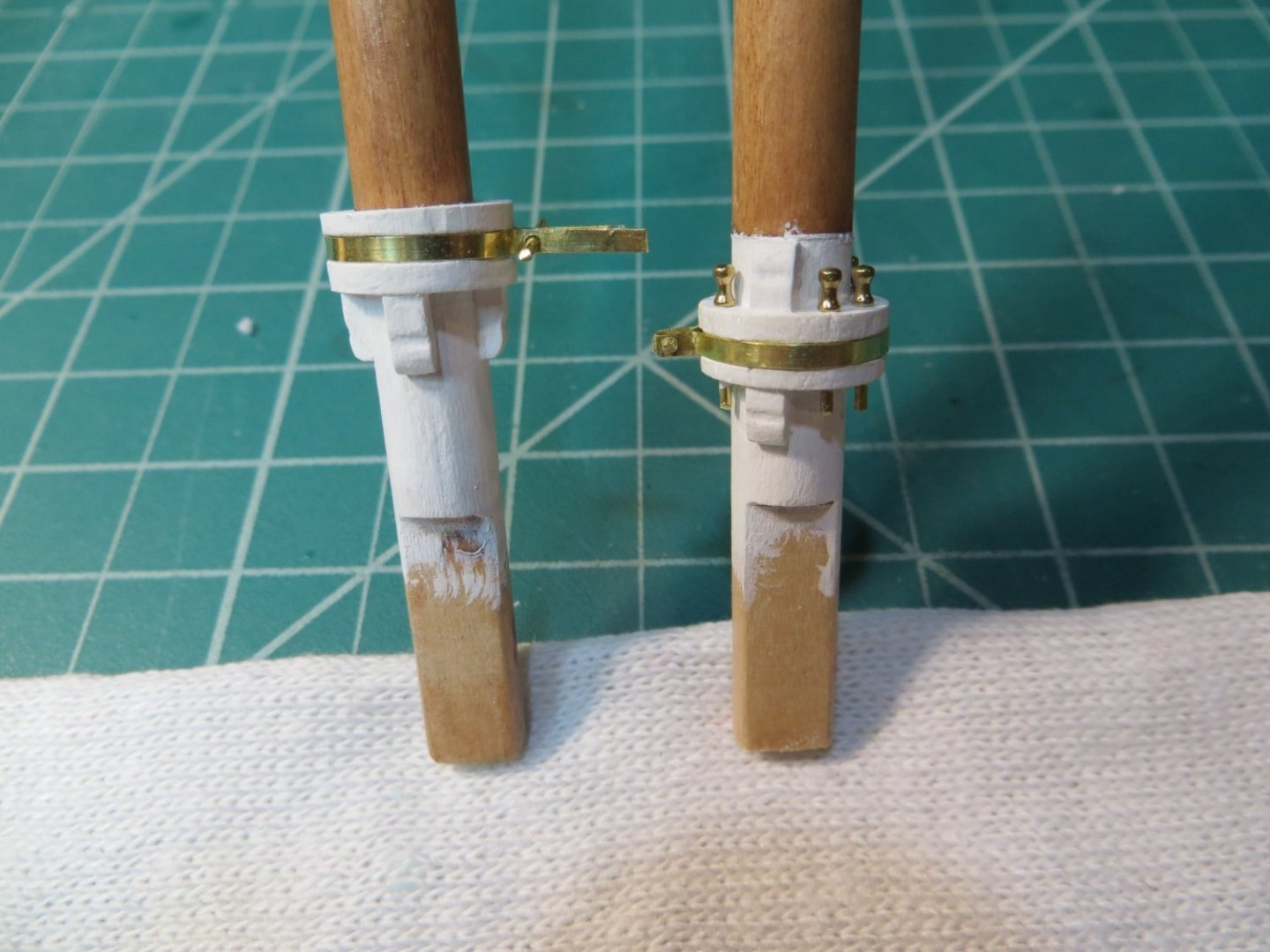
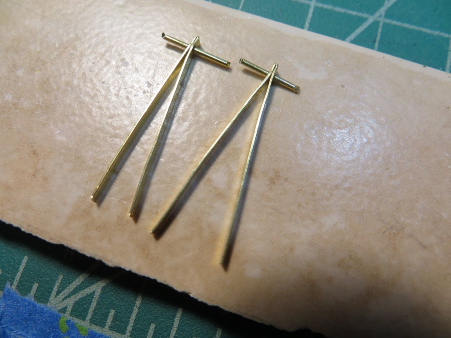
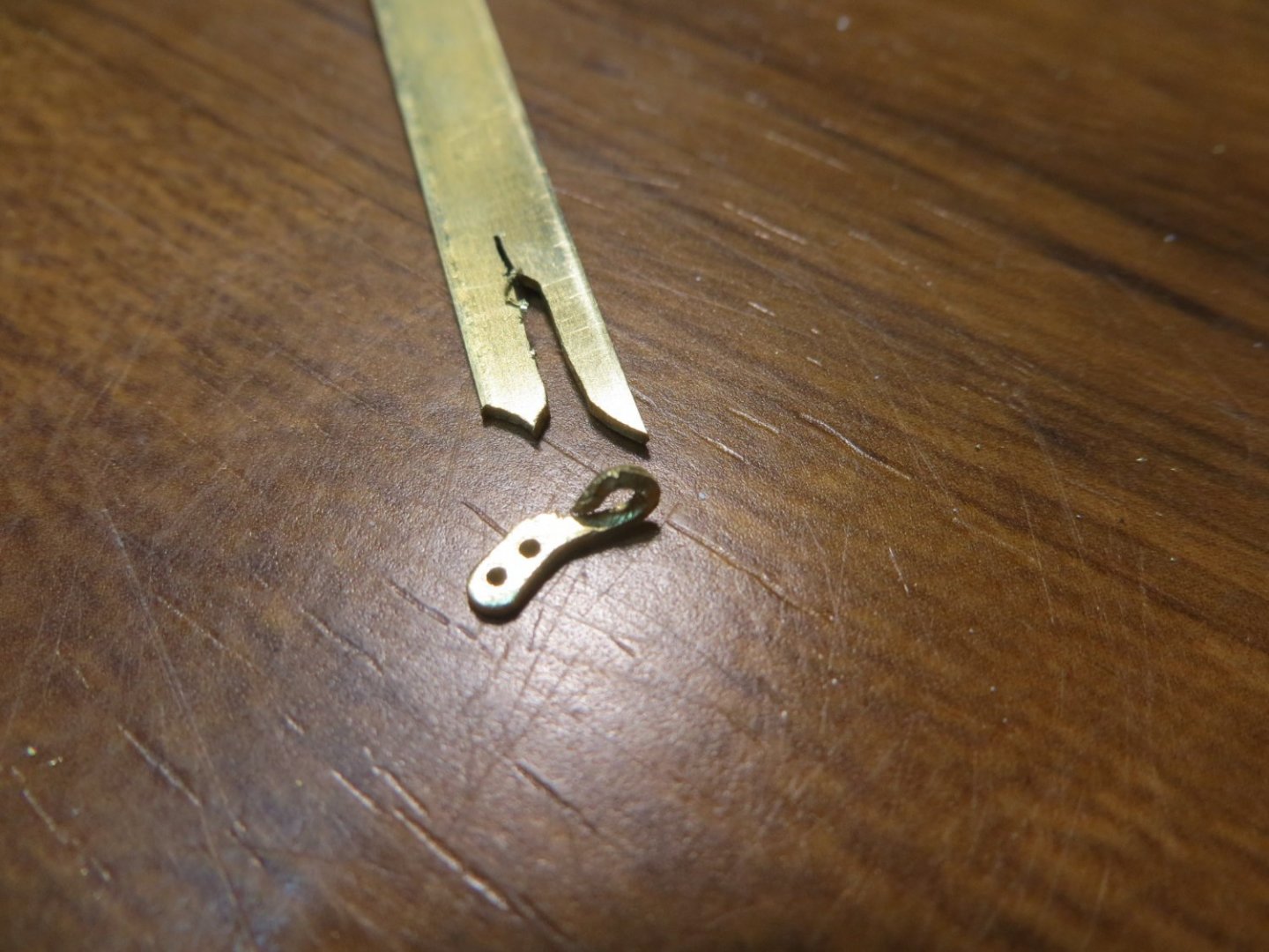
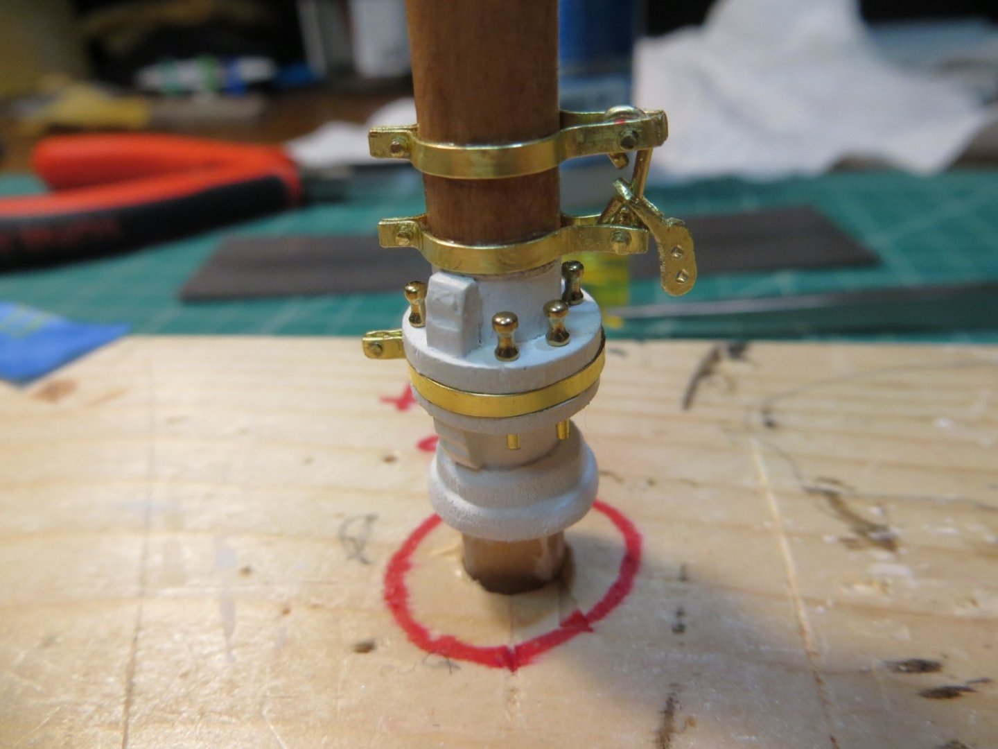
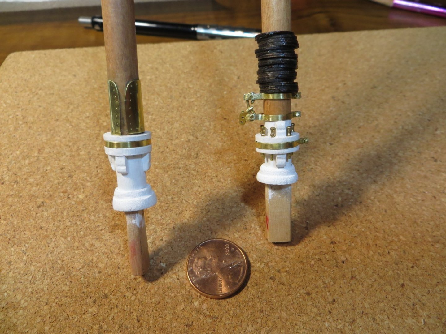
Originally posted on Nov. 4, 2021 Construction of the Masts The following basic workflow was followed for building the masts: 1. Size, cut, taper and stain the lower mast and top mast sections for both the fore and main mast. 2. Build the various parts for the lower masts, working from the bottom up. The fore and main masts were worked on simultaneously, since they are so similar. a. The parts in this step include, in order: pin saddle & chocks, belaying pins, boom rest & chocks, metal chafing sheet for main boom jaws, gooseneck, mast hoops, mast coats, trestle trees, spreaders and all of their brass fittings, mast bands, cranes & mast caps 3. Finish out the top mast details, including top mast bands, gilt balls, flat trucks & mast hoops. 4. These steps took me quite a bit of time to complete. 125 hours and 70 calendar days 5. I’m going to break the masts into several build log updates Building the 4 mast pieces 1. The 4 masts must be cut and tapered according to the plans. Both lower masts are made from 5/16” dowel rods provided in the kit. I matched them up directly on the plans to get the length. 2. However, before cutting them to length, I shaped the bottom portion that fits below the deck. I made sure they had the correct depth and that the shape fit snuggly into the holes in the deck. Then I marked the exact spot where the mast stuck out above the deck and then aligned that mark to the plans. I then marked and cut the top to length. 3. Both masts have to be tapered. Most of the mast is not tapered, just the portion where the trestle trees go and on up to the top. I left the very top part where the mast cap goes a little large so I could do some final shaping when I was working on the brass mast caps later on. 4. The top masts are made from 3/16” dowels. They are shaped on all 4 sides. A shoulder is carved near the top per the plans. Leave some width for additional shaping to fit the trucks and gilt balls on the top later. 5. I took a scrap pine board and drilled 4 holes to make a stand to hold the masts while working on them. 6. I stained all 4 masts with Minwax Cherry stain, to match the deck. Building the Pin Saddle and Boom Rest 1. I decided to follow Suburban Ship Modeler’s process for building the pin saddle and boom rest from scratch. The kit provides laser cut halves for these, but this does not provide a way to attach the recessed metal band between the pieces. I believe this is a beautiful looking detail. 2. I purchased some ½” dowels from the hardware store. I cut a 2 – 3” section off the dowel. I placed it vertically in the vise and drilled through the center with a 5/16” drill bit on my drill press. It took a couple of attempts to get a nicely centered hole. The result was a donut that will fit over the bottom of the lower masts. 3. The pin saddle, which goes on the fore mast, requires holes for belaying pins. I used my pin vise to drill these 7 holes in the top of the dowel. It is easier to do this while the piece is long and can be secured better. 4. Next step was to secure the piece in the mini-vise horizontally. I carved a 1/16” wide x 1/64” deep recess into the circumference of the dowel that will accommodate the kit provided brass strip. I measured how far to make the recess from the cut end based on the plans. When done, I cut the pin saddle off the rest of the dowel, matching the width on the bottom end same as I did for the top. 5. I used another section of the drilled dowel to make the boom rest in the same way. The boom rest goes on the main mast. It does not require holes for belaying pins since these are on the fife rail. 6. The next step is to make 8 chocks which are used to hold the pin saddle and boom rest on the masts. In the picture below you can see the shape that needs to be carved into the chocks. I cut strips that were longer then required. I clamped these down on a scrap board and filed and sanded them to shape all at one time. I cut off the excess strip wood to get the right size chocks. The fore mast has 2 sets of chocks above and below. The main mast has all 4 chocks below. 7. The pin saddle, boom rest and chocks were glued to the masts. I taped off the top edge and gave everything below a couple of coats of white paint. Adding the Brass Bands, Belaying Pins and Brass Sheet to Lower Masts 1. To make the recessed brass bands, I fitted a length of brass strip around the saddle/rest and squeezed it tight with pliers to form a joint on the other side. I marked the position for drilling holes in the band and removed it. Holes were drilled on the drill press using a #64 bit. The strip was repositioned and brass rod was inserted into the holes. I used CA glue to hold everything in place. Once set, I clipped off the excess bit of brass strip and filed the end to round the edges. I really like the way the brass looks in contrast to the white wood. 2. Belaying pins were inserted into the pin saddle for the fore mast. I have to confess, that I guess my pin saddle is a bit too tall. When I test fit the belaying pins only a short nub stuck out the bottom. So, I cut them in half and glued one half on top and the other half sticking out the proper length below. Sometimes you just have to improvise! No one will know, unless they read this blog! 3. I bought a piece of 0.005” thick brass sheet to make the chafing piece that protects the main mast from the boom jaws. It was cut to shape using scissors. The hard part was getting the CA glue to hold the metal securely to the mast. It took a few passes with glue. I used a fine point punch to make the tiny holes to simulate it being nailed to the mast. Gooseneck & Tack Shackle 1. Above the pin saddle on the fore mast there are a couple of bands called the “Gooseneck and the Tack Shackle”. This assembly holds the Fore Boom to the mast. 2. I started by making the tack shackle, because I thought this would be difficult to make. Since this piece holds up the fore boom, it needed to be heavier than the 1/64” stuff in the kit. I purchased a package of assorted K&S brass strips a while back. I selected a piece that was 1/32” thick. I drew the shape on the end of the metal strip and drilled a couple of offset holes close to the end. 3. I used my jeweler’s saw to cut out a piece that was shaped like the shackle but with a long neck. I used files to refine the shape and smooth the rough edges. I bent the long neck back on top of itself to form a ring. 4. I made the gooseneck bands by bending 2 lengths of brass strip in half, drilling a hole close to the bent end and inserting a brass rod in each hole. I also cut 2 more rods to use for pins on the other end. A third “connector” rod with an eye on one end was also made. 5. I began the assembly by attaching the 2 bands around the mast. The loose end has to be bent so there is enough space for the connector rod to fit in between the 2 pins. It was tricky sliding the top pin in between the ends of the band with the connector eye in between. It was even harder determining how long the connector had to be so the bottom eye is bent just right to fit between the 2 bands with the tack shackle in the middle. After a lot of trial and error I got it right. I applied CA glue to hold everything in place. However, note that the tack shackle needs to move freely on the connector. I won’t know if I really got it right until it’s time to attach the fore boom! That completes the construction for the bottom of the lower masts.

- 96 replies
-
- 2
-
-
- model shipways
- bluenose
- (and 1 more)
-
Originally posted Sept. 15, 2021 Building the Bowsprit The following steps were used: · The bowsprit has to be shaped, built and painted · Fabricate and install numerous brass metal pieces · Attach the rigging lines to the bowsprit before mounting on the ship · Mount the bowsprit on the ship · Complete by attaching the rigging lines to the hull Construction Steps 1. Start with a ¼” dowel rod provided in the kit. This needs to be tapered and sanded to shape according to the plans. Mark the top, bottom and sides of the dowel clearly to start. Carefully measure the reference points and transfer them to the dowel. There is no tapering on the bottom side. This would have been much easier if I had a milling machine. So, I used my needle files to cut notches the required depth to match the taper at each reference point. I used sanding paper/sticks to do the tapering. I used my new “mini-vise” to keep the dowel anchored down firmly for sanding. 2. Begin sanding the dowel according to the reference points. Go slow and measure often. Test fit on the ship to get the bowsprit to fit through the hole in the front. Create a square section at the end to fit thru the bitts before the Sampson post. My first effort was a mess!! Good thing the kit provides enough dowel to make a second try. This time it turned out much better. 3. Make Jib Stops. Cut two strips of 3/32” square strip wood to 2 – 7/16” length. Mark the locations for the notches. I taped them together with blue tape and clamped them in the mini-vise. I planned to use thin (0.008”) weight rope. I used the square needle file to make the holes 1/32” deep and 3/64” wide. 4. Glue the jib stop strips to the bowsprit once cutting is completed. 5. Paint the assembled bowsprit black outside the ship and white where it sits on the deck. 6. I made a jig stand to hold the bowsprit while pre-rigging the lines Making the metal fittings 1. Use the 1/64” x 1/16” wide brass strips provided in the kit to make the bands on the bowsprit. Three bands are required at the tip end of the bowsprit. a. At the very tip is a metal band with 3 rings extending off from the band. Cut a strip of brass and bend it in a ring to fit on the end of the bowsprit. The other end extends to form one of the fins on the ring. Drill a hole in the fin. Cut two more strips and drill holes at one end of each. Solder the 3 pieces together as well as the main band shut. Cut off the extra material close to the holes and file the corners to form it to a rounded shape. b. Make another band with 4 rings the same way c. Make a 3rd band that has no rings d. Sorry, I did not take any pictures of this process. I’m still learning how to solder halfway decent! 2. I used some electrical wire to mount the bowsprit to the stand I made before attaching the bands. 3. Slip each band on, in order, starting with the plain band and CA glue them in place. 4. Install 2 eyebolts according to the plans. These will be used for rigging the sails. 5. The next step is to make 5 staples, 4 links, 4 plates, 7 shackles & 6 turnbuckles out of brass. I used the method published by Suburban Ship Modeler to make these metal pieces. You can see my pictures for the turnbuckles. I tried several methods for making the shackles based on reading the blogs from other modelers. None of them worked for me. I finally did it this way… a. Cut an 8mm long strip of brass to make a shackle that has 2 sides that are 1/8” long and a top width of 1/16”. b. Use a fine punch to make a pilot point in each end. Drill holes with drill press using a #64 bit c. Round off both square ends with a square needle file to form a ring shape around the holes. Hold it tight with needle-nose pliers. d. Mark the center and using my fingers, fold it over only about ¾ of the way using the handle end of my favorite curved tweezers (this provided the correct width). Press down hard against the tweezers to flatten the top a bit. Finish the bend with it centered just right! e. Use the tweezers to place it in the needle-nose pliers so the round side is sticking out the side. Use the square needle file to shave a little off each side & round the edges to give it the shackle shape. Making Turnbuckles: Brass tubing lined up on the drill press. Next pic - Hole drilled into half the side of brass tube Tubing pieces filed and cleaned up Brass rod inserted to simulate the turnbuckle Pre-Rigging the lines off the ship 1. All the ropes were temporarily attached to the bowsprit using a bent piece of wire in the shackle. That way in the final steps shown below, you can test fit the attachment point at the hull end, mark the exact spot in the line where the eye splice needs to go and remove the rope to make the eye splice and wrap the line in the Serv-O-Matic and reattach everything back on the ship. 2. Backropes attach with a shackle to ring band 2. Insert some bent wire in the shackle to temp hold it. 3. Guy lines attach to ring band 1 using shackles and turnbuckles. 4. Bobstays are secured to the bottom of the bowsprit. The Upper bobstay connects to a staple that is attached under the bowsprit, with a turnbuckle. The Lower connects to Ring 1 at the bottom ring via a shackle and Turnbuckle. 5. The foot ropes are too hard to make off the ship. Wait until later to begin these. Installing and rigging the Bowsprit to the hull 1. Slide the bowsprit through the hole in the bow and use CA glue to secure it. I never bothered to make the tenon & mortise at the base of the bowsprit. I knew the chances of that fitting when I got to this point were slim and none. I just placed a few drops of CA glue at the Sampson Post, between the bitts and at the hole in the hull. The fit was already snug and held it in place. 2. Jumbo Jib Traveler Block – carved from a piece of strip wood according to the plans. Shape it with a curve so the bottom sits flush on the bowsprit. A staple is made BUT NOT GLUED until later when the ring for the jumbo jib boom is attached. 3. Gammon Iron – is a piece of metal that wraps around the bowsprit secures it to the bow. I followed Suburban Ship Modeler’s instructions for making this piece. The hardest part was positioning it and CA gluing to the bowsprit and hull. 0.032” brass rod is used to make “fake” bolts. 4. Bobstays – I started working from the bottom up to avoid having to work inside of the lines mounted above. Bobstays attach to plates that wrap around the keel. Plates for the Upper are shorter than the Lower bobstays. CA glue the plates in place, insert fake bolts in the hull and attach threaded bolts to run through the single holes at the front end. Use an eye splice and a link to secure them to the bolts. I used threaded bolts and nuts I purchased from ModelMotorcars.com for this last step. Plates for Bobstays: Upper bobstay completed. Notice the rest of the bowsprit lines "pre-rigged" and waiting to be attached. 5. Guy Lines – attach to plates mounted to the hull just below the eyebolt for the cathead. Plates have a bolt on the aft end and a staple at the other. Cut a brass strip from the kit strips. Drill 3 holes as required and paint the strip black. CA glue in place. Attach a fake bolt and the staple. Use an eye splice and a shackle to attach to the plates. Ropes are 0.021” black line. 6. Backropes – attach to staples that go in the rail forward of the catheads. A link connects a turnbuckle to the staple. An eye splice connects the rope to the TB. 7. Foot ropes – attach to staples below the rail on each side of the bow using a shackle. On the other end I simply tied this thin rope to the shackle that was already on Ring 2. Ropes are 0.008” line. An eye splice is used on the hull end. I used the following method to tie the “stirrups” as done by Suburban Ship Modeler: a. Tie the stirrup to one guy line. b. Run it under the foot ropes and up to the guy line on the other side. c. Tie it to the other guy line, being sure to leave the right amount of slack so it has the right curve. d. Use another piece of black thread to tie the foot ropes to the stirrups. e. Secure all the knots with a little dab of CA glue. f. I dabbed a little CA on the stirrups to help stiffen them in the ideal hanging position 8. Jib Stops – short ropes used to tie down the jib sail when not in use. These use tan rope. Tie knots in the ends of the 10 short pieces of 0.008 tan rope and insert them into the holes. Just let them hang down. Pictures of the completed bowsprit:


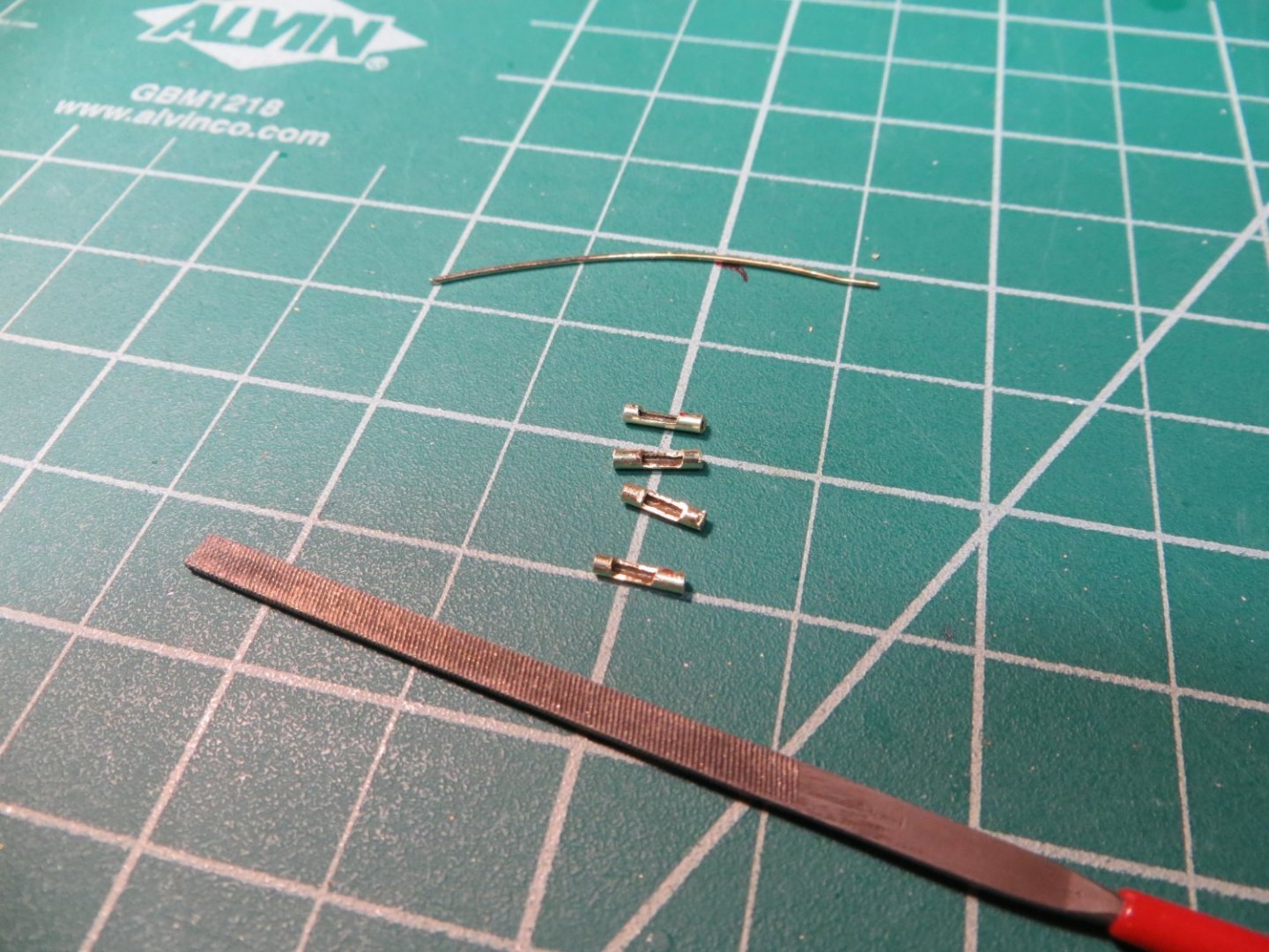
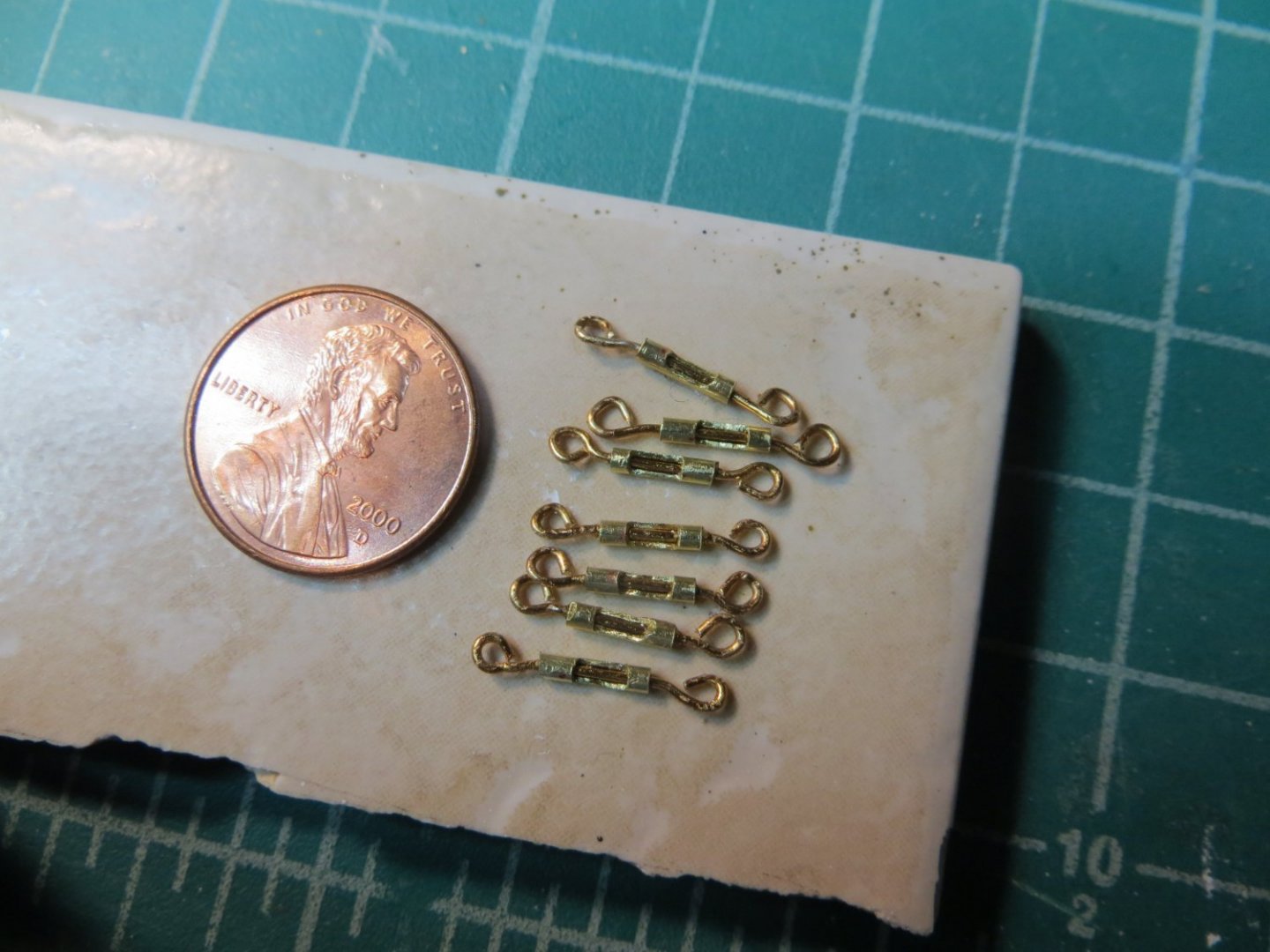
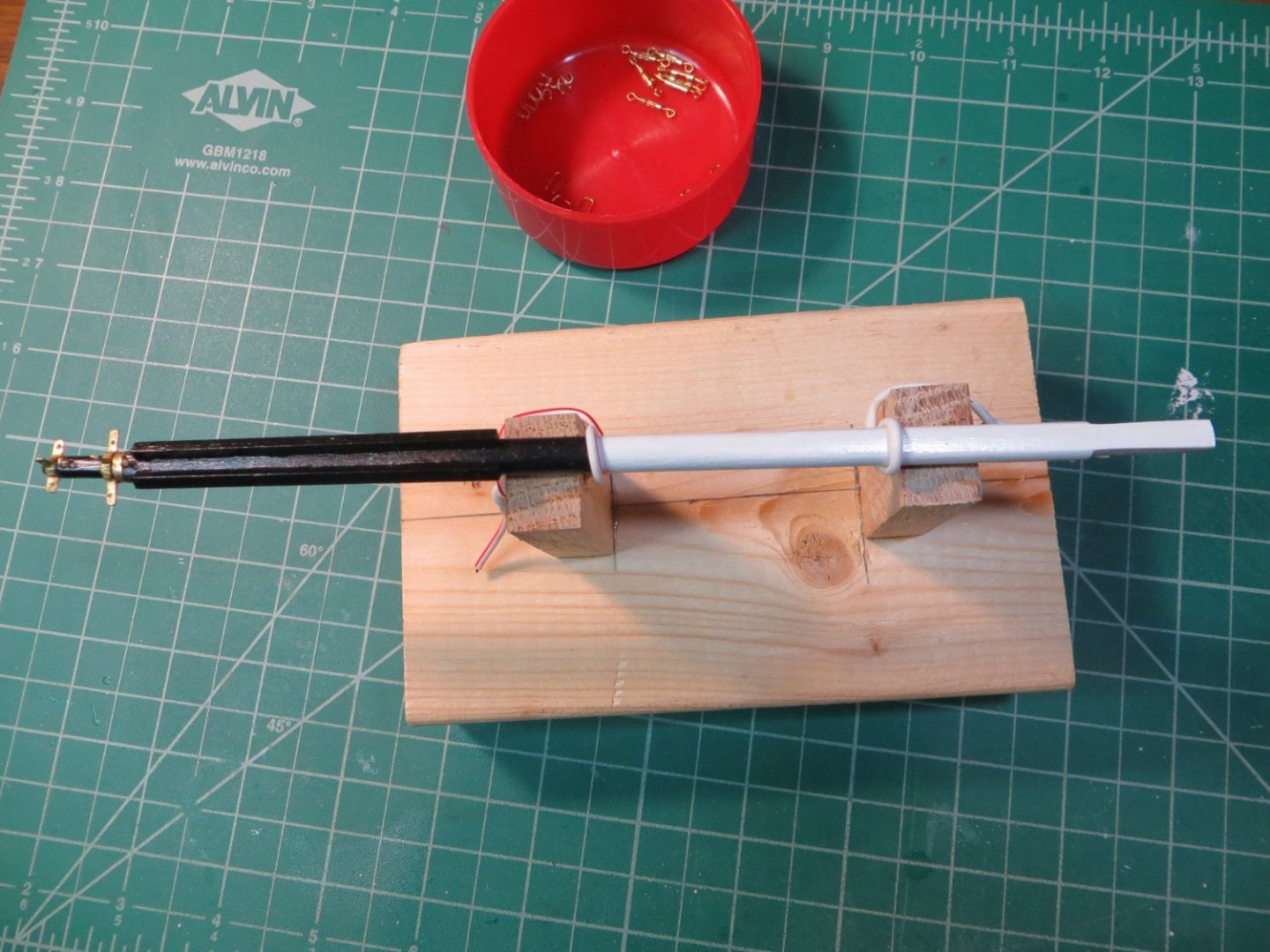
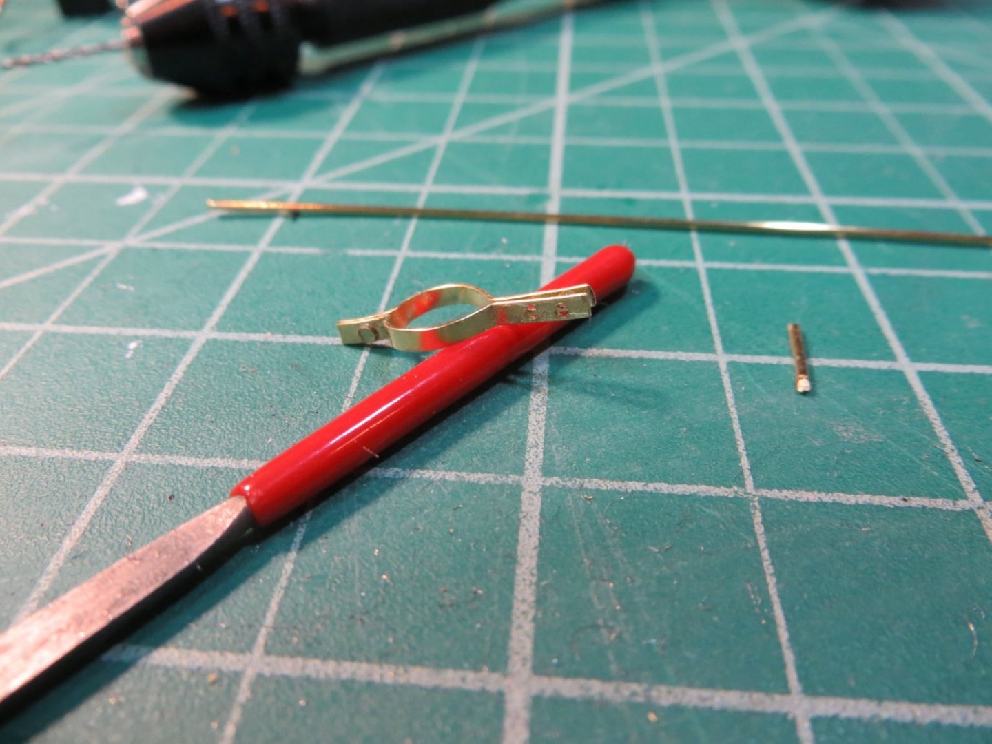
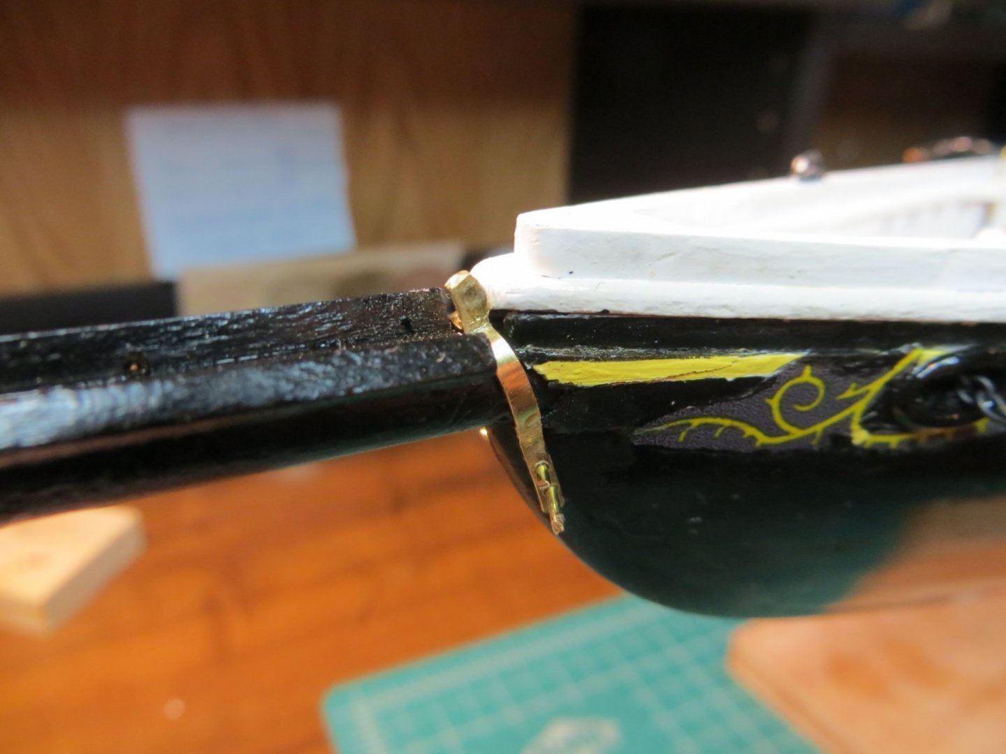

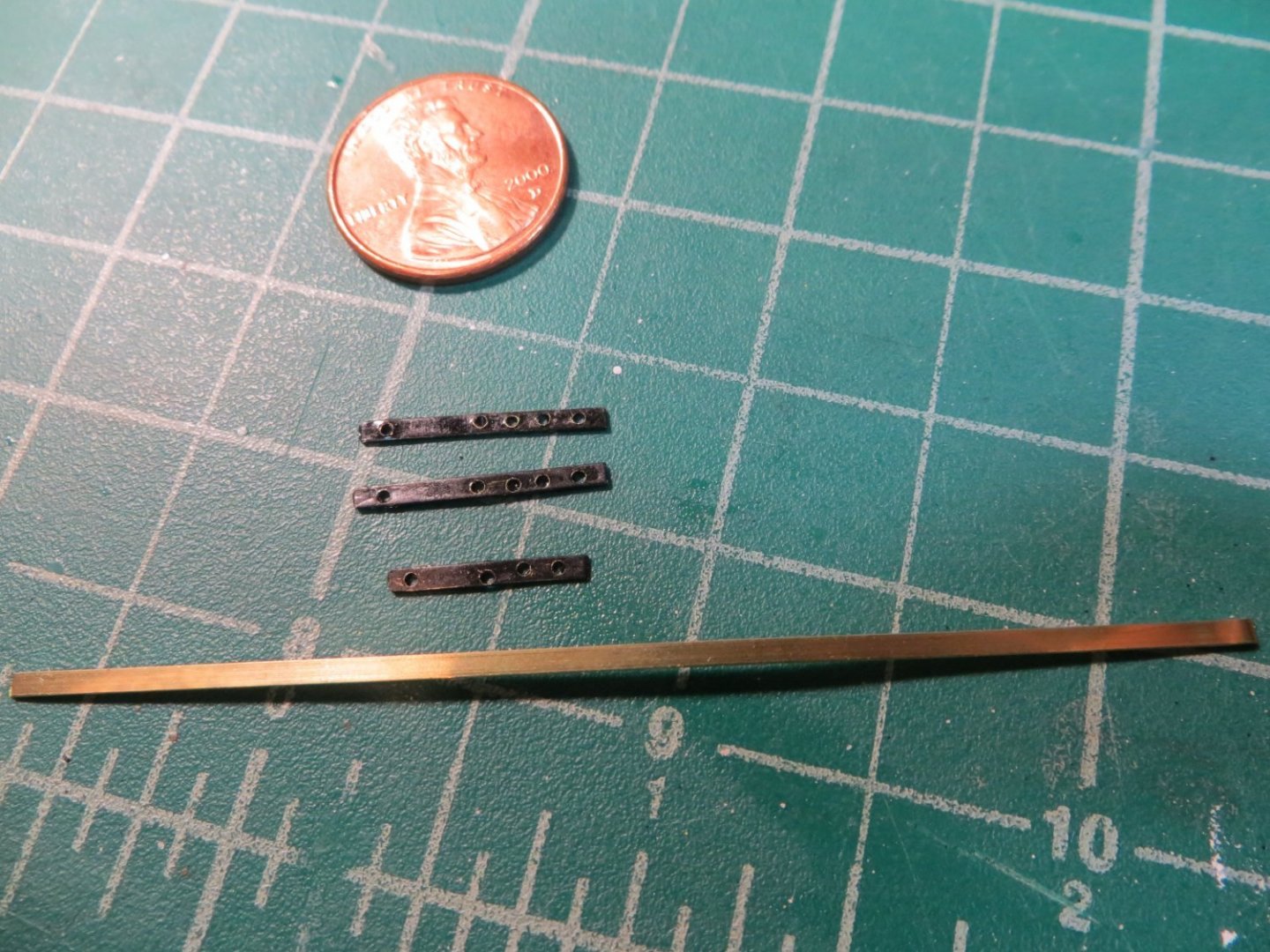
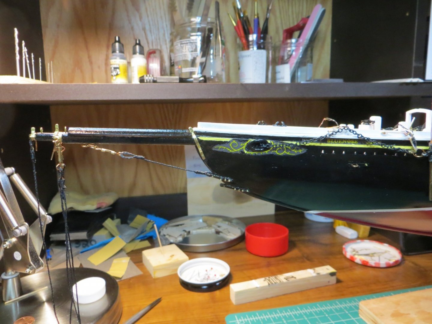
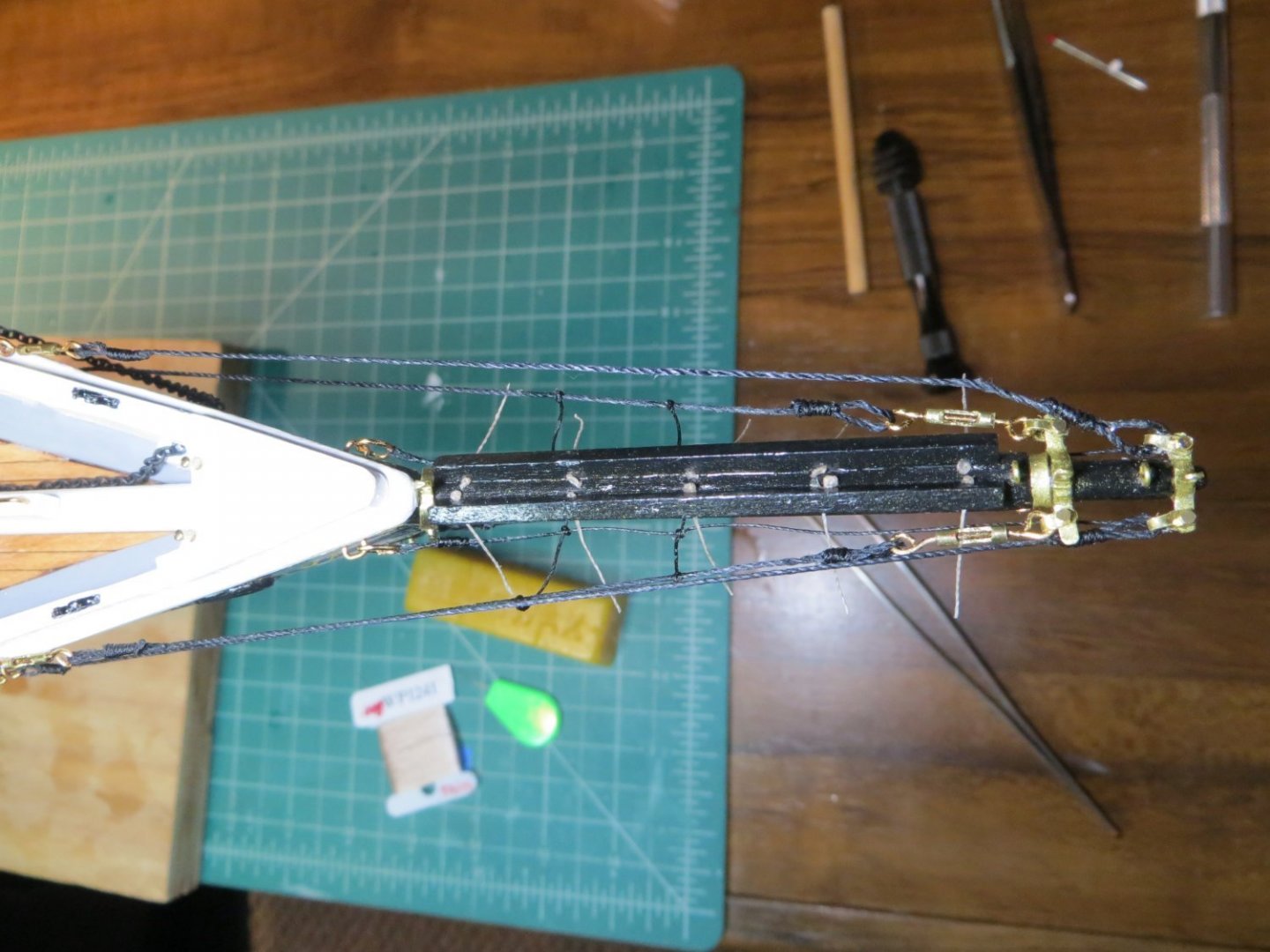
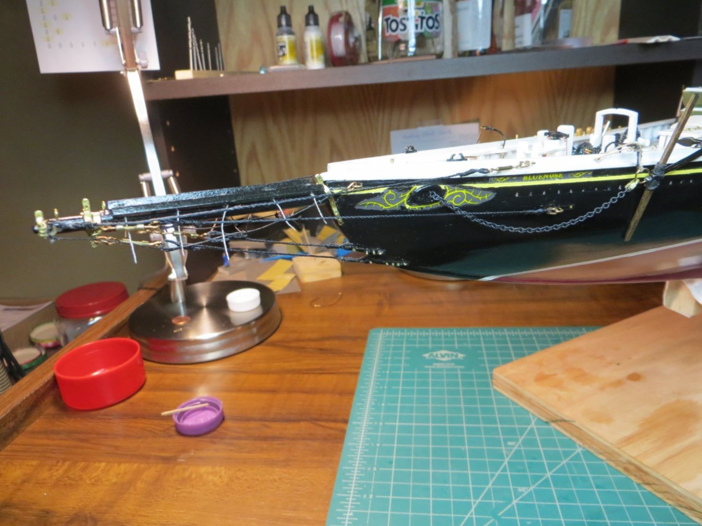

- 96 replies
-
- 2
-
-
- model shipways
- bluenose
- (and 1 more)
-
Welcome Aboard!!
-
Originally posted Aug. 1, 2021 Dories, Oars & Kids Making the dories turned out to be one of the more difficult tasks so far on this build. I tried using the jig provided in the kit, but I ended up with a mess. So, I decided to follow the approach of Suburban Ship Modeler. He built some interior frames to hold the birchwood sides in place to make each dory. First, I took measurements from the plans to determine the size and shape of the frames. I purchased some 3/32” thick basswood to make the 5 frames per dory. I used my mini jewelers coping saw to cut out the pieces after tracing the shape from my drawings onto the wood sheet. Unfortunately, this wood was too soft and the pieces kept breaking. I switched to some 1/16” basswood sheet that I’ve been using for other things. Although it is thinner, it was harder and seemed to work better for me. It took a lot of time to hand cut all the pieces for each of the 4 dories that I decided to build. I used the actual kit provided pieces to trace the shape of the floor and stern pieces onto my sheet wood. I also used the birch sheet wood from the kit to make the hull sides. Since, I had a lot of extra wood here, I cut them so I had 3 birchwood strips for each side and I overlapped them so they looked like the sketch in the plans. I had a lot of adventures learning the best way to hold and glue the sides to the frames. I had more luck gluing my fingers to the wood then where I wanted it glued. After some frustrating trial and error, I developed some techniques. In the end I spent almost 70 hours and 34 calendar days building those 4 little dories. They are not perfect, but I think they will look good on my deck. Here are the steps I followed. Construction Steps 1. Cut out 1/16” thick pieces according to my drawings. Also, cut the floor, stern piece, stern brace and bow piece for each dory by hand with the jewelers saw. Sand them to their finished size. 2. Mark the locations for each frame – A to E on the floor. Also, mark the location of the cleats that fit between the frames. 3. Glue the frames to the floor a. Glue the stern piece to its brace first, then when dry, glue to the floor w/ CA glue for a fast hold b. Glue the bow piece w/ CA glue c. Glue the “cleats” across the bottom of the boats between each frame. Make these from 1/32” strip wood. I made the cleats a little long and then trimmed them to size with flush cut wire cutting pliers 4. Cut 6 strips for each dory from the 1/64” birchwood parts in the kit. Make the top strip a little wider to account for overlapping. 5. I soaked each piece in hot water to make them easier to bend and hold. Glue the bottom strips on each side first. Then the second strip, slightly overlapping the lower strip. Cut the final strip wider than the others to cover the top third of the dory 6. Trim the birchwood with the wire cutters to be flush with the top of the frames and finish with a good sanding 7. Cut the horizontal seat support rails from square strip. I soaked this wood to get them to bend to the shape of the hull. Measure and cut out the seats. Mark each seat’s position since they are custom fitted. Don’t glue them in yet. Hand paint the seats white. 8. Now paint the dories before gluing on the railings. I painted the hull with Vallejo Camo Grey Green (71.116) and the inside with Beige (70.917). Do this before adding the white seats and railings. 9. I cut the railings from 1/64” birch sheet wood that I purchased on-line. Turn the boat upside down to trace the shape. Measure the thickness of the planks + frames to determine the width for the inside outline. Make them a little bigger on the outside so I can sand them flush with the hull. I cut the first two as separate halves. But I found it was easier to handle and glue them on when I made the last two as a single piece. I painted these white and glued them on. 10. After the glue dried, I trimmed the over-lap of the railings with the flush-cut wire-cutters and then sanded the edge smooth. 11. Make the splash rail from 1/32” square strip wood. Glue them on then hand brush white and touch up everything 12. Make the Thole pins. 12 per dory. Use 1/32” brass rods. Drill holes with the #64 bit in the pin vise. Glue in w/ CA 13. Add the little rope loops at the stern. 14. I measured and cut the kids that the boats are stacked on, according to the plans. I painted these Light grey. 15. The oars were a little more difficult because they are so tiny. I used 3/64 x 3/32” strip wood. We need 4 total, but I stacked 6 of them and clamped them together, to have extras in case of breakage (glad I did!). I heavy sanded the initial shape with this stack. Then did a lot of careful sanding of each oar to get to the final shape. 16. I painted them with the camo grey-green and made the tips the same yellow as the hull waist stripe to give them a little character. I also wrapped a little tan rope around the handle end as a personal touch. Everything was glued in place with CA. 17. The final step was to add some eyebolts to the kids. I bent some S-hooks then seized tan rope to them. These were secured around each stack to hold the boats down on the deck. The Completed Dories installed on the deck:
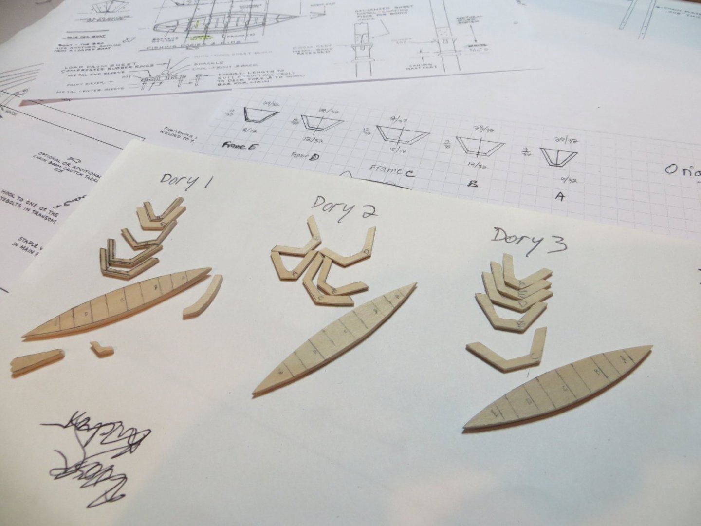


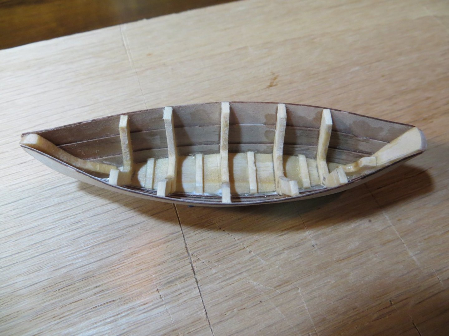
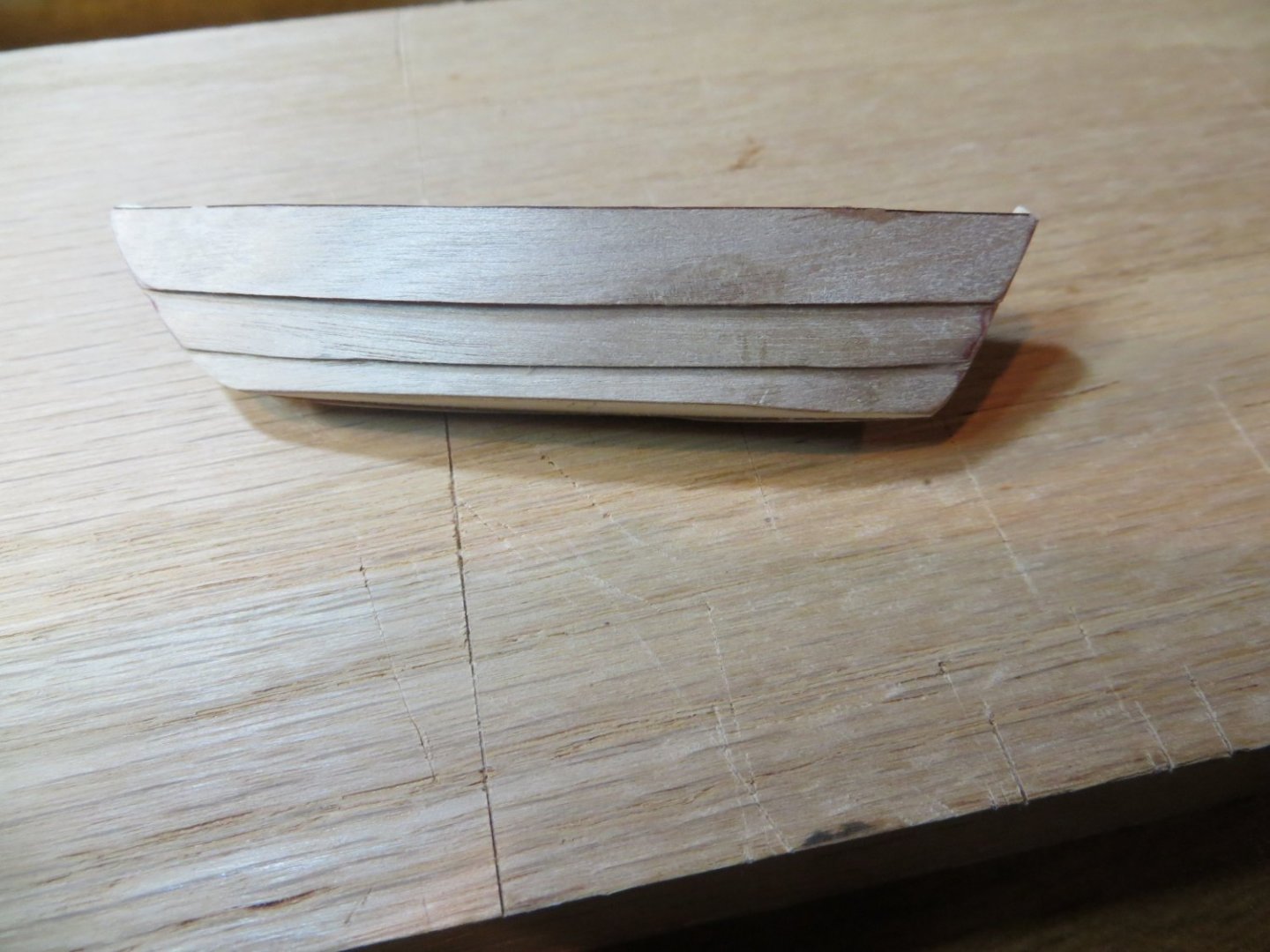


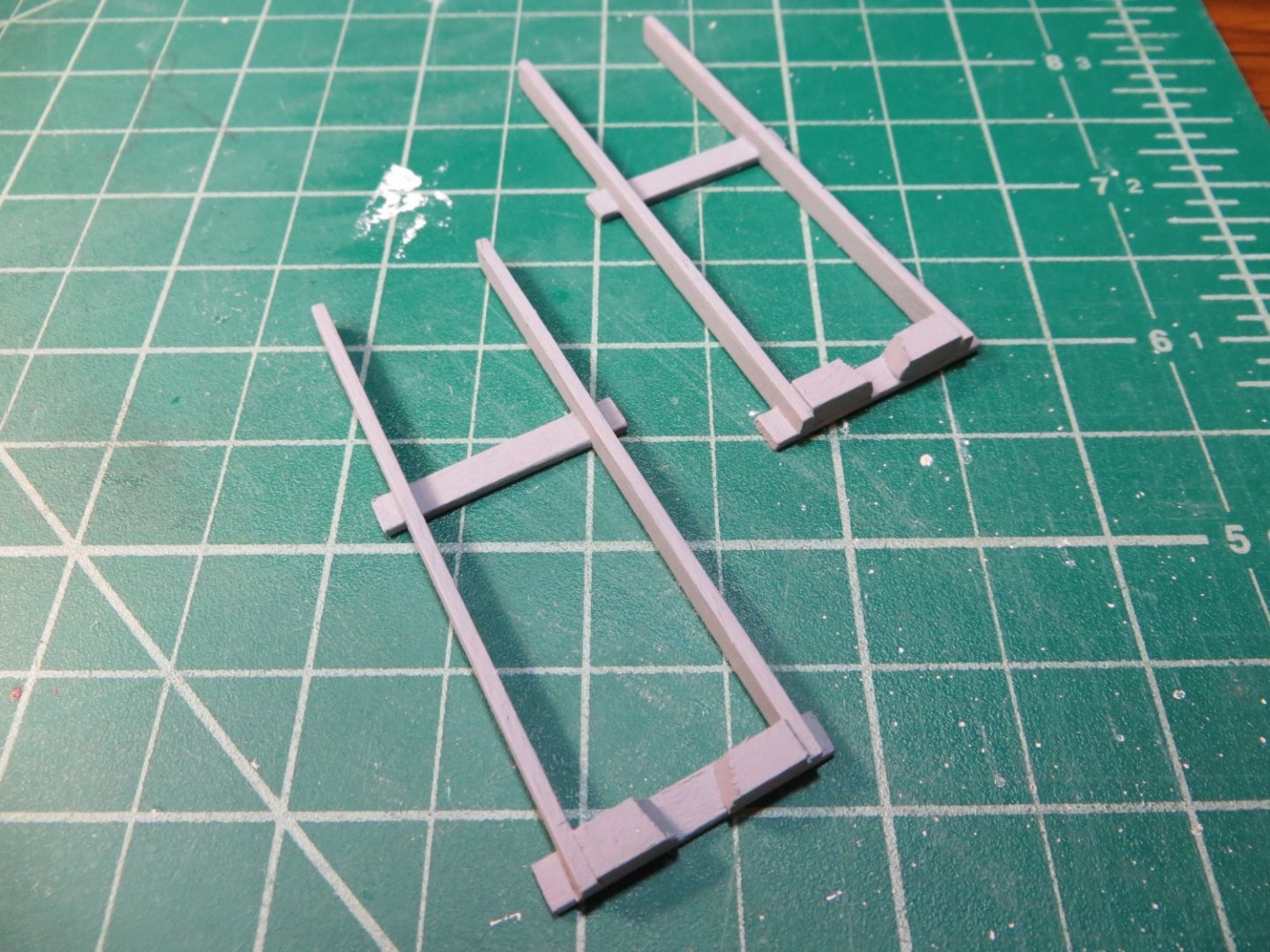
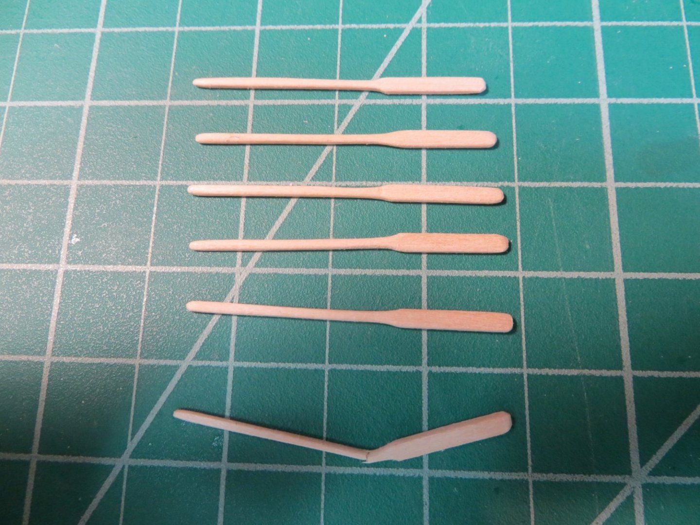
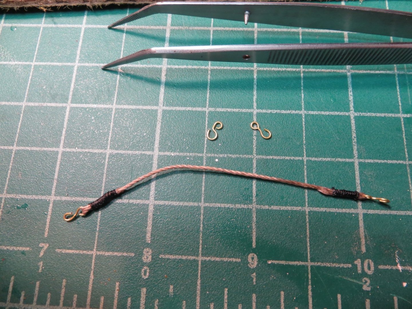
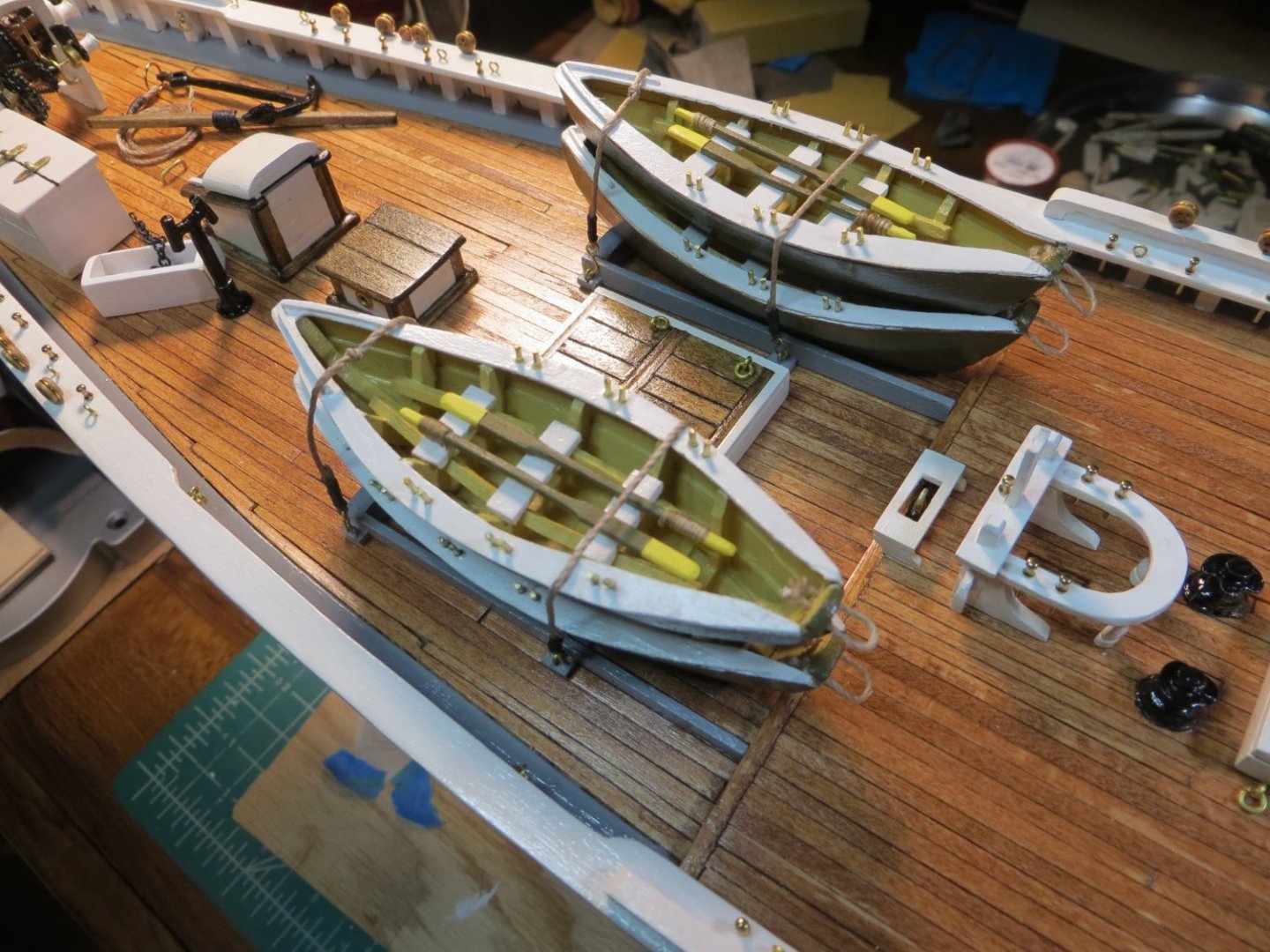
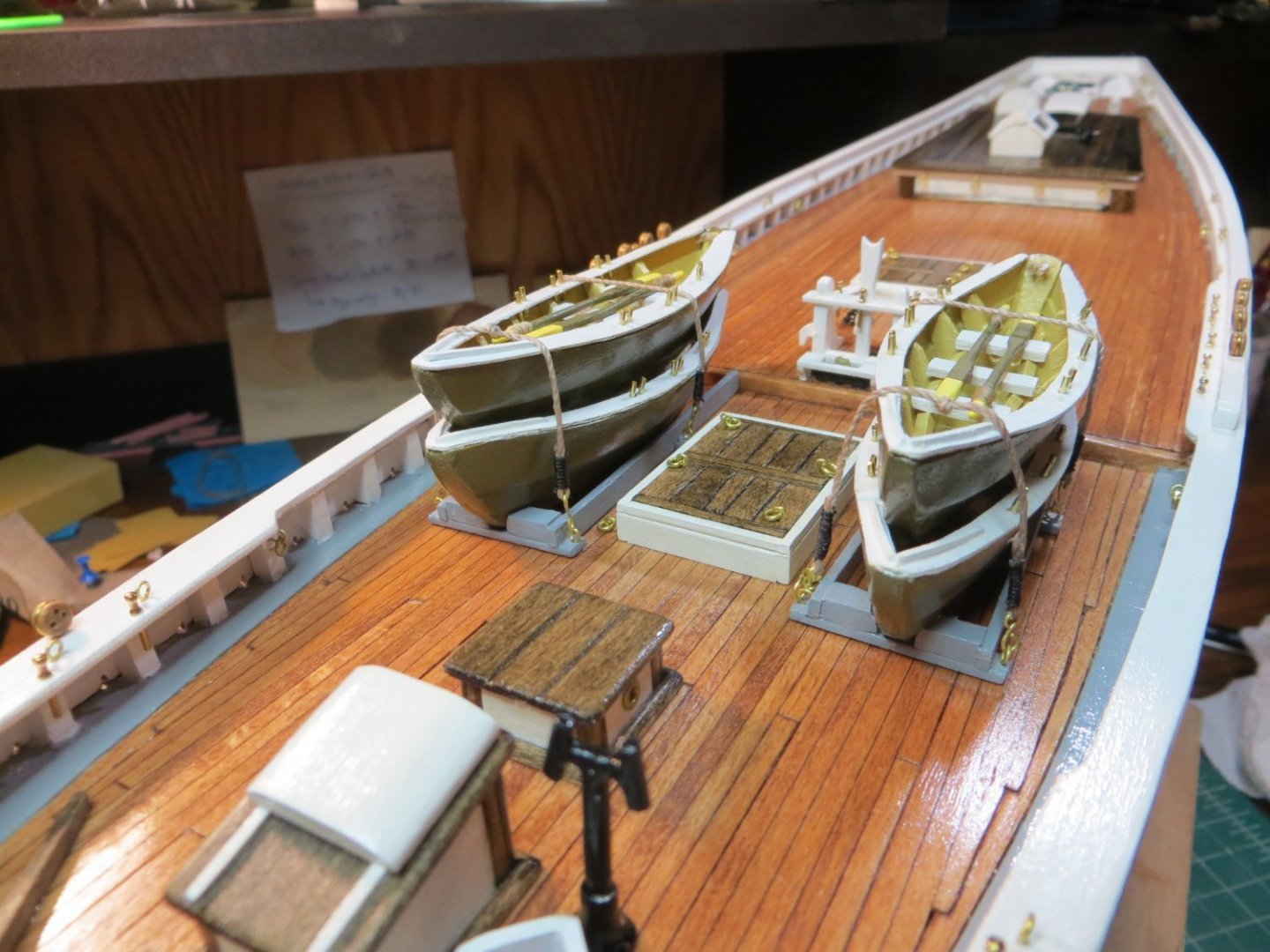
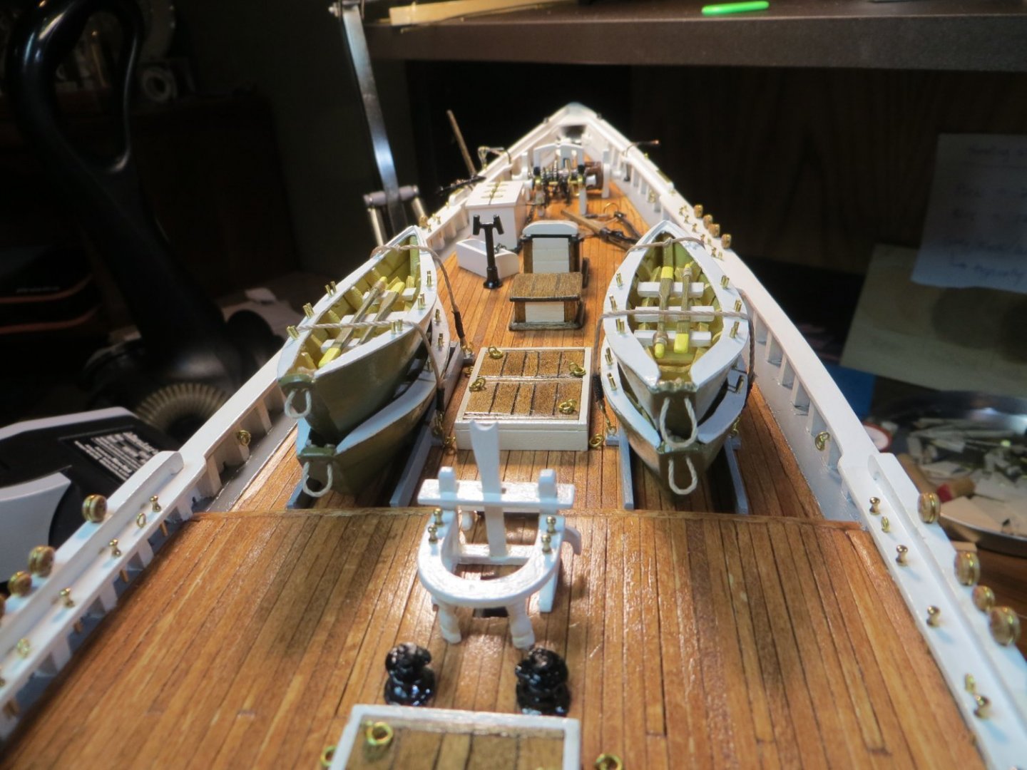
- 96 replies
-
- 3
-
-
- model shipways
- bluenose
- (and 1 more)