HOLIDAY DONATION DRIVE - SUPPORT MSW - DO YOUR PART TO KEEP THIS GREAT FORUM GOING! (Only 20 donations so far - C'mon guys!)
×

LucienL
-
Posts
122 -
Joined
-
Last visited
Content Type
Profiles
Forums
Gallery
Events
Everything posted by LucienL
-
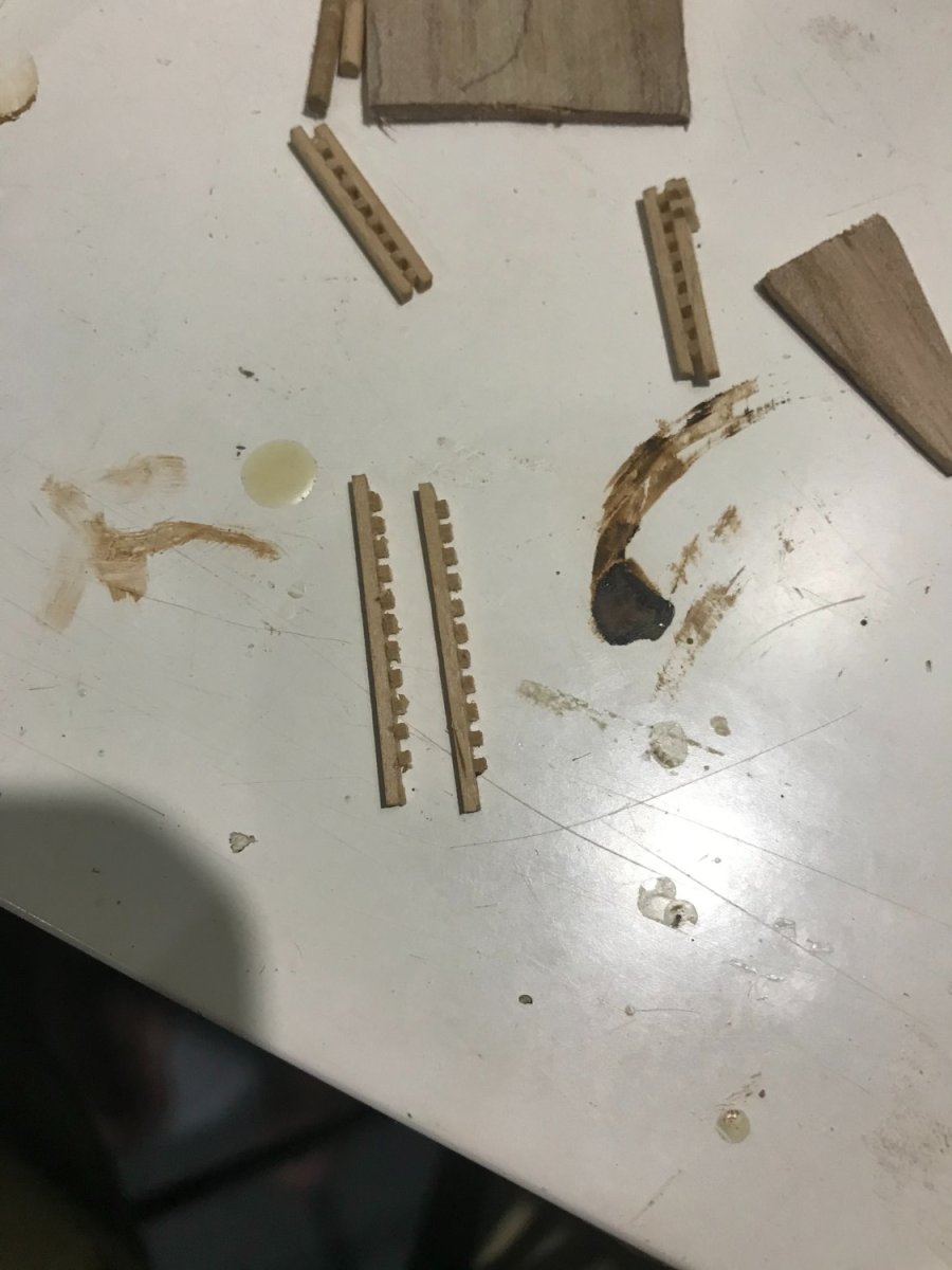
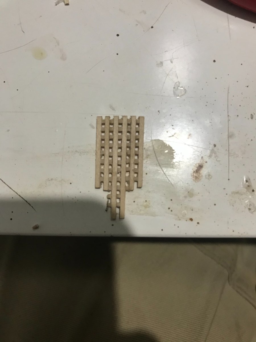
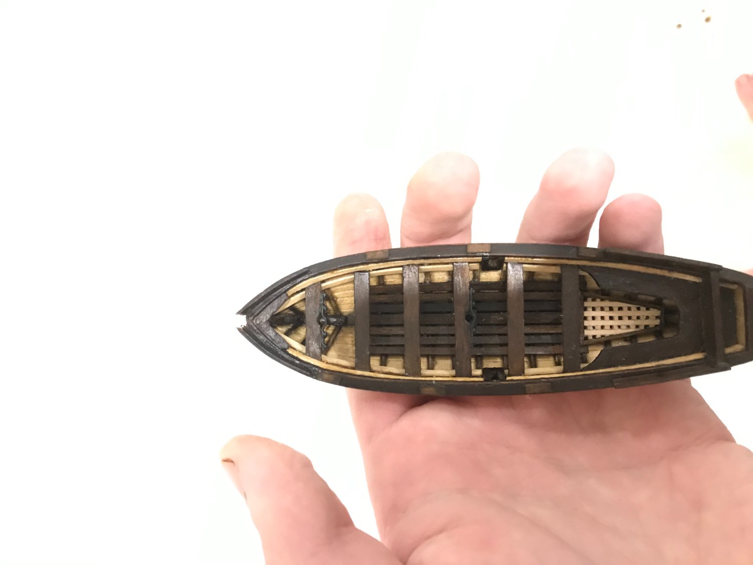
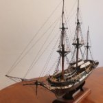
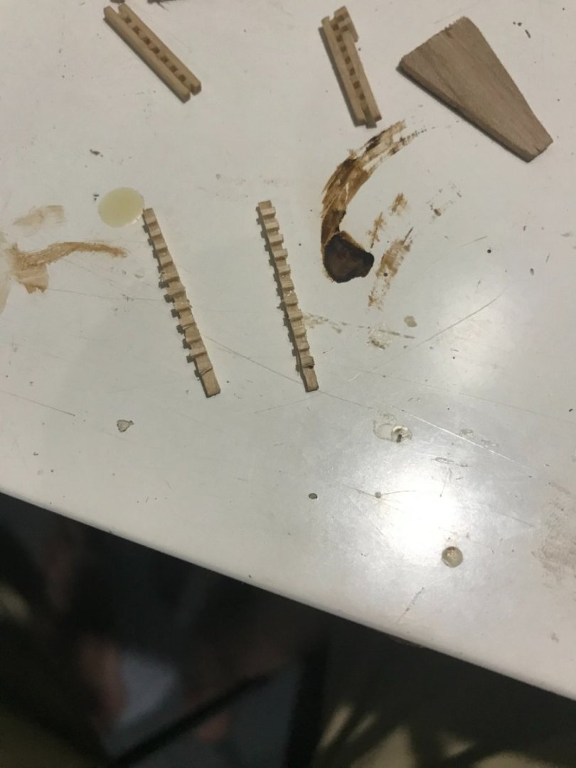
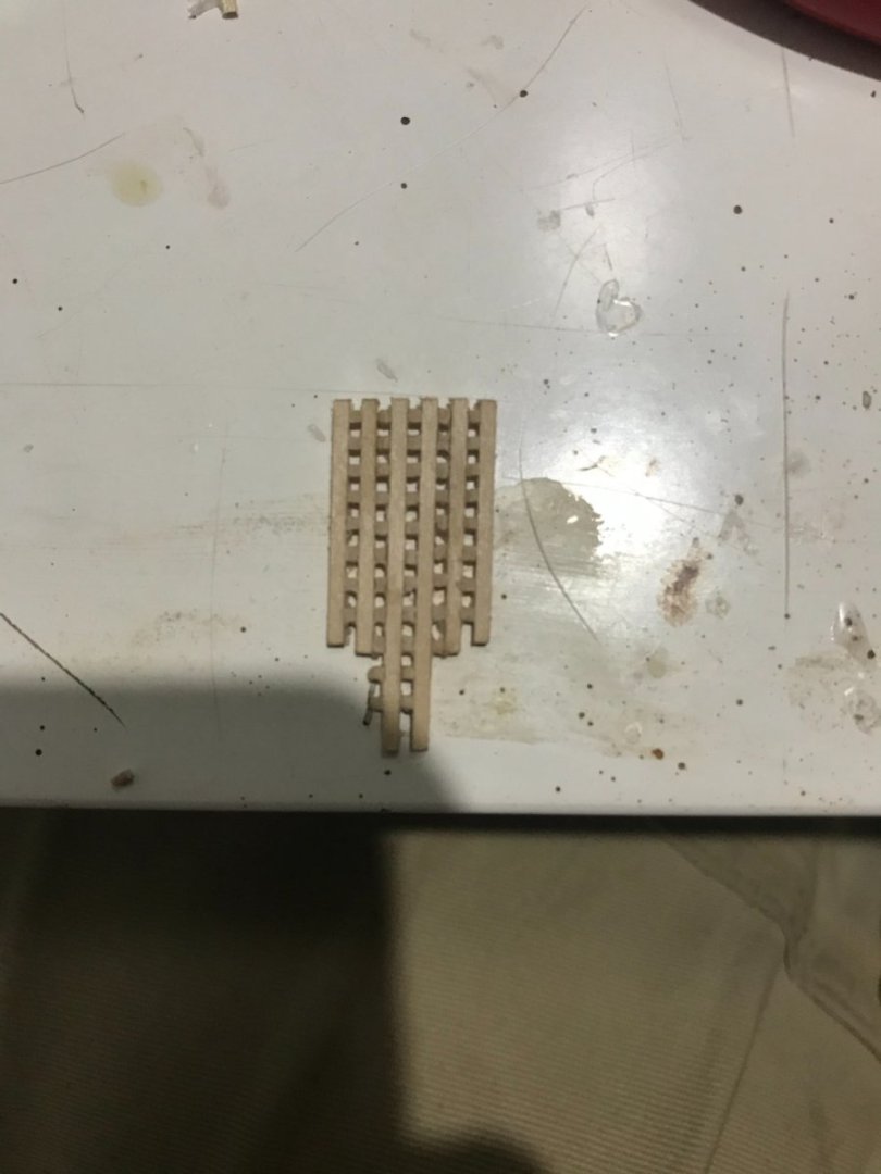
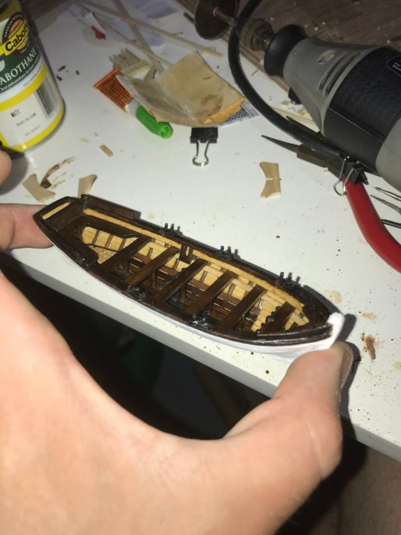
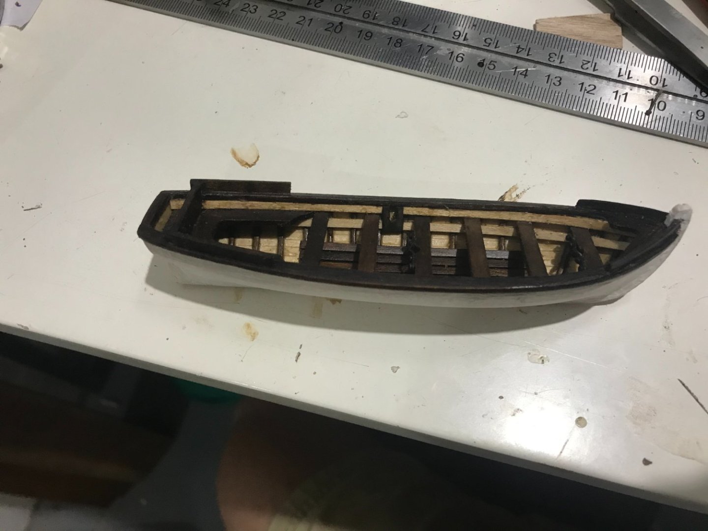
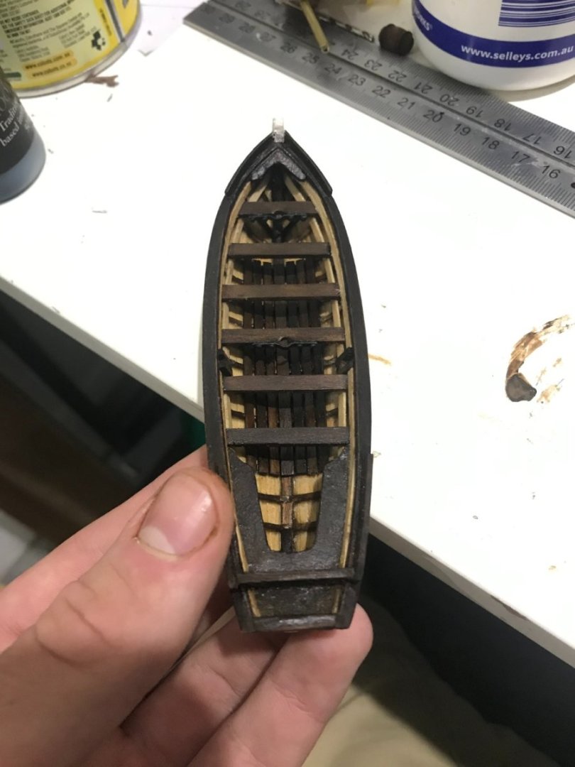
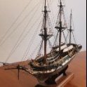 Been finishing up some of the last details on the yawl. The big one was the grating that makes up the quarter deck. I glued some 1 x 1 mm sticks to a 3 x 1 mm stick using some 1 mm spacers. Then I cut them in half to double the amount of grating made, which could then be glued together. In only had a small amount to make, so this relatively inefficient process was still effective. I’ve also done the thwart stanchions, mast steps and the tholes, which means that this one is basically done aside from boat gear, which I might combine with some of the other boats a bit later.


-
Hi Roger, thank you, that makes much more sense
-
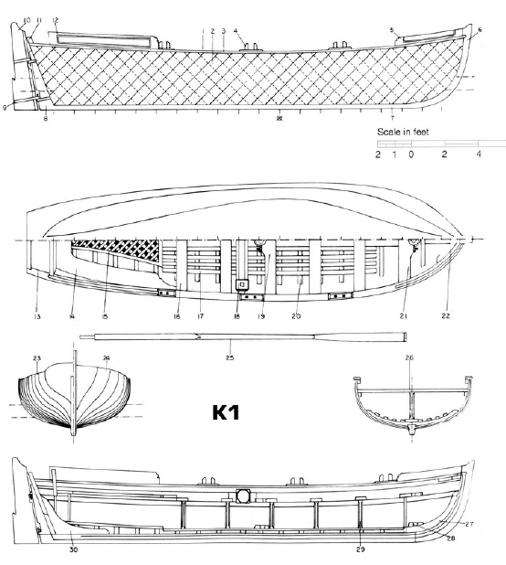
I'm currently working on building the Beagle's boats, starting with the 26 ft yawl. I'm drawing from the anatomy of the ship, which outlines the plans here. My question is regarding the aftmost tholes, i.e. the ones that appear to be positioned for a rower seated on the stern-sheet bench. This seems as though it would present a very awkward rowing position and this individual would be forced to place their back to the thole and move the oar to their side. Is this something that is seen on other boats? How realistic is it that a rower would be able to use an oar positioned as such?
-
Hey capella, this is probably too late, but I found that shading the edges of the planks before fitting them helped. Alternatively, you could go as you have and outline the planks. Then run over it with a razor blade (or even a broken piece of glass) to clean the planks and hopefully keep the grooves
-
In the wise words of Samwise Gamgee "It's the job that's never started as takes longest to finish". I'm sure your boats will look great! I was also dreading this a bit and it did turn out to be much easier than I expected.
-
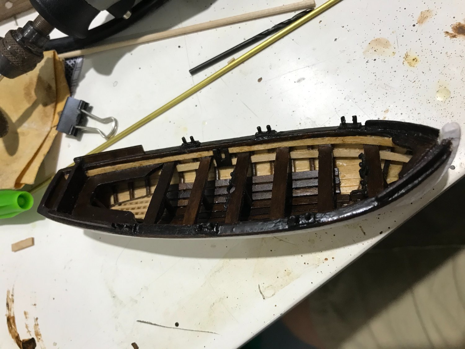
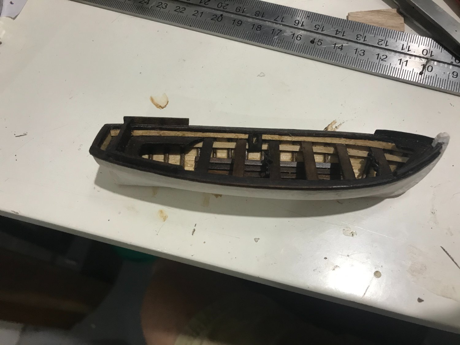
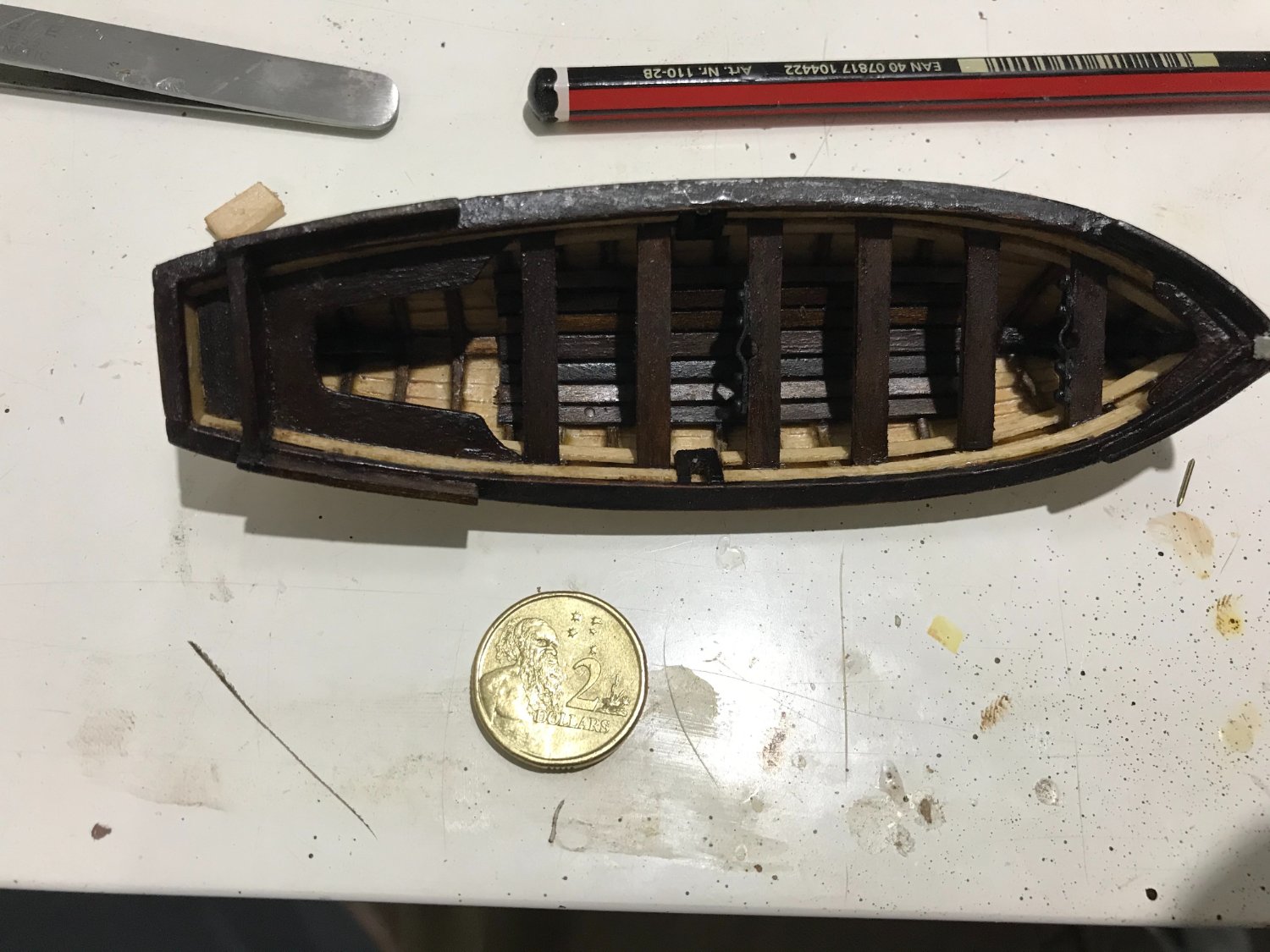
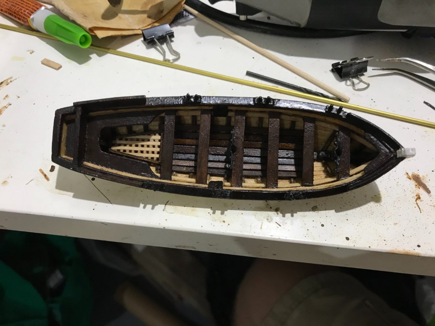
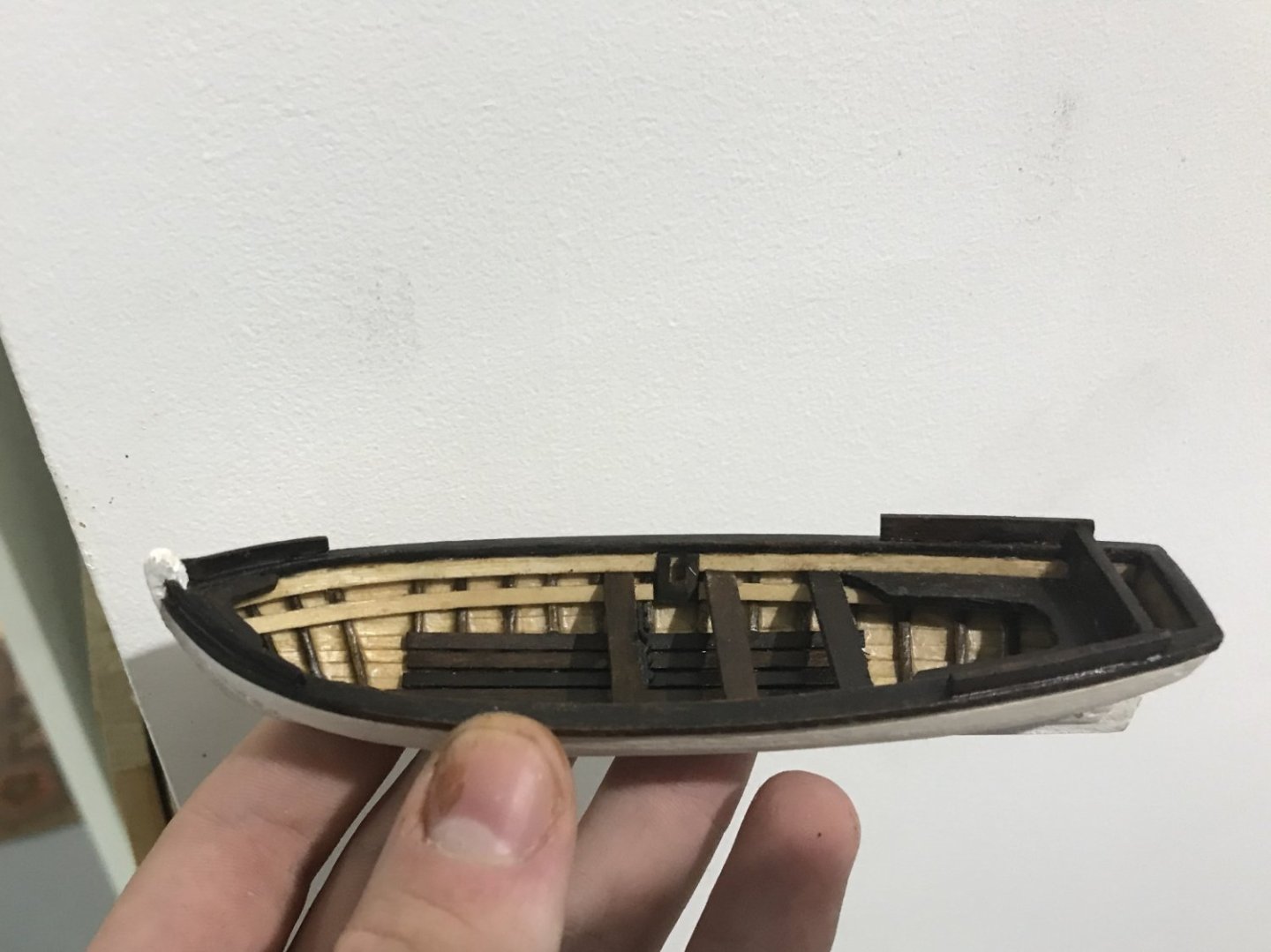
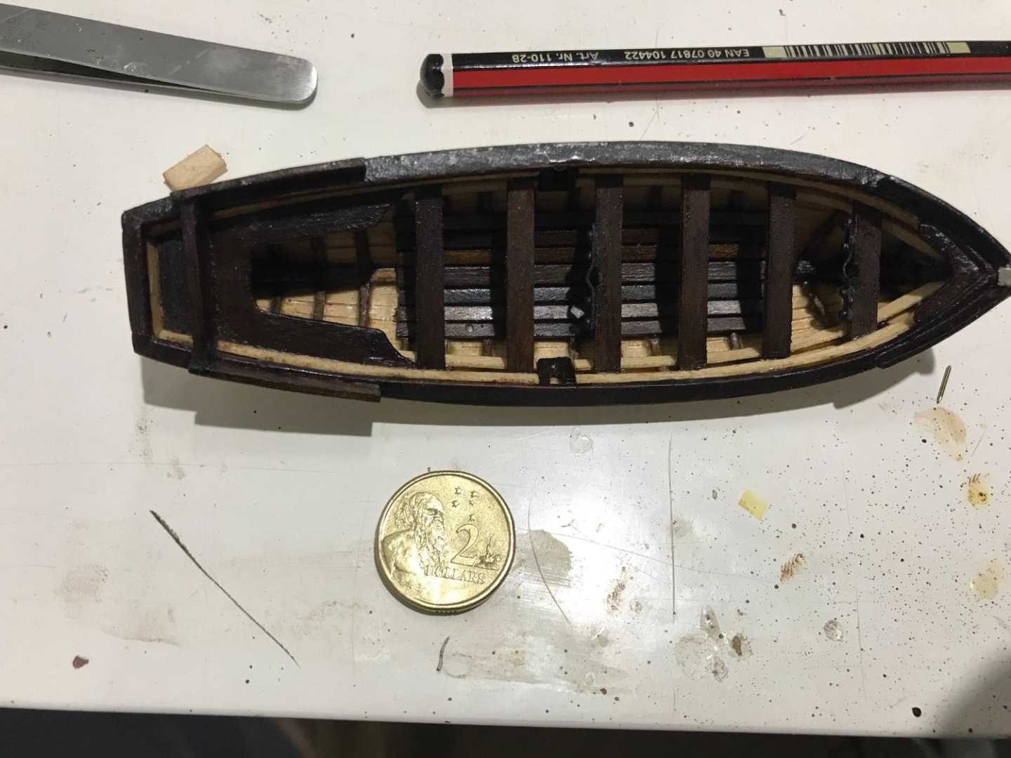
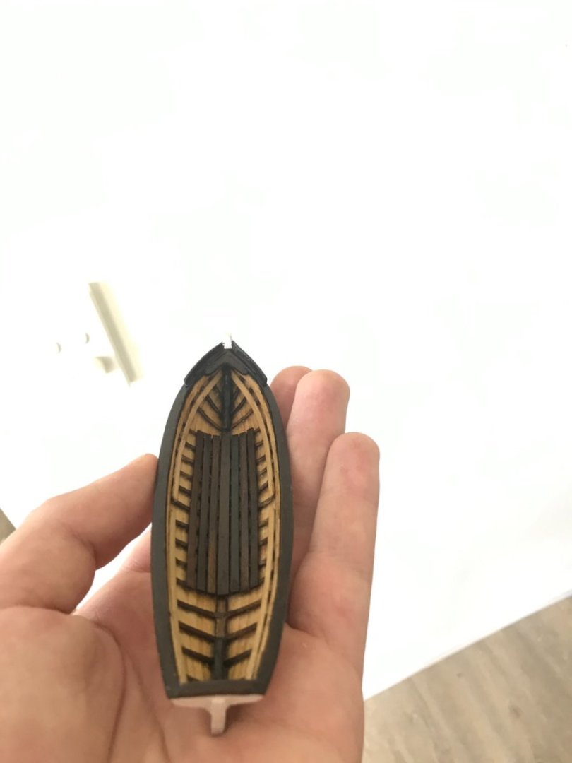
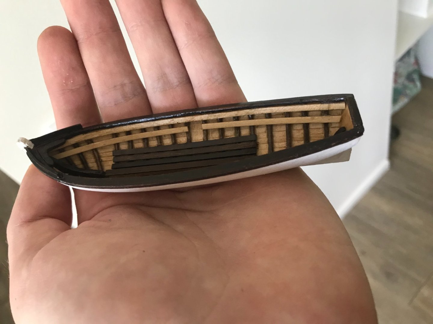
Another smallish update but has taken some time. I fitted the stern-sheet bench and back, which took ages to make from scratch and sand to fit properly. I also added a few thwarts, the third one is the mast thwart and is only dry fit. The mast helpers are made from 1 mm wide brass strips and painted back. I’ve used the kit nails to fit them in, they’re probably a bit too big but add some nice detail. Also made the windlass holders. I think I will make up a full windlass and strap that to the deck as part of the boat kit. I’ll probably also make up some oars, a grapnel, the rudder, masts and sails and chuck in a barrel. I’m drawing a lot from my experience on my first build: The Bounty’s Launch to make these little boats. I think my sheer clamp and thwart raisers are too wide, but I can live with them. And finally, with all the thwarts in. No pennies in Australia, but our 2-dollar coin is around the same size (I think) Next steps are to make the grating for the quarter deck, do the mast steps, tholes and the thwart stanchions. Then I should be able to move on to fitting it into the main boat and building the 23 ft cutter. Feeling motivated and keen at the moment, so should be able to keep making progress (unless the gratings kill me).
-
Hi Capella, great build so far, looking forward to seeing your progress. The planks you describe definitely seem like the ones that should be A20 (even just going by quantity) it's interesting that the dimensions are off though. Although, the 5 mm planks are probably too wide for scale so that might actually be a bonus (or they've improved the kit).
-
Hey Rob That's an impressive list of stuff you're thinking about! You've definitely found a lot of limitations with this kit. I will follow along with interest. One of my biggest frustrations is also the cannons and boats (as well as the belaying pins). I've also been working on this kit and trying to incorporate as many improvements from AOTS as I can. My biggest bottlenecks so far in terms of motivation, time and learning have been coppering the hull, making cloth hammocks and scratch-building the small boats (I also probably want to make my own sails).
-
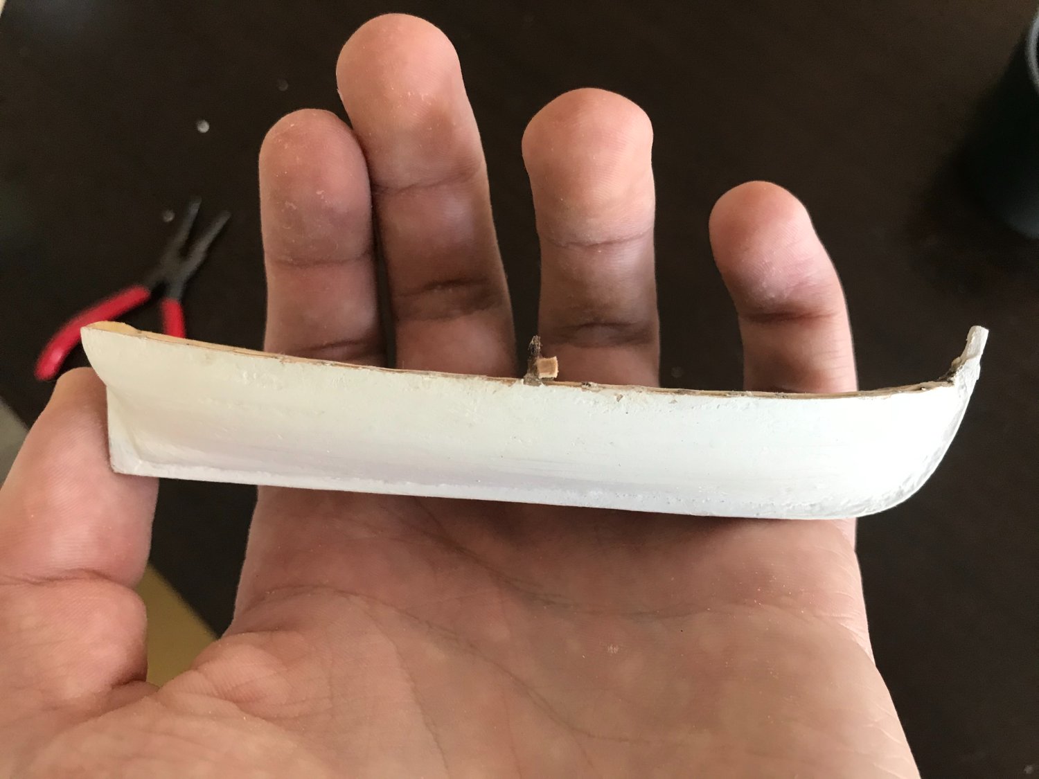
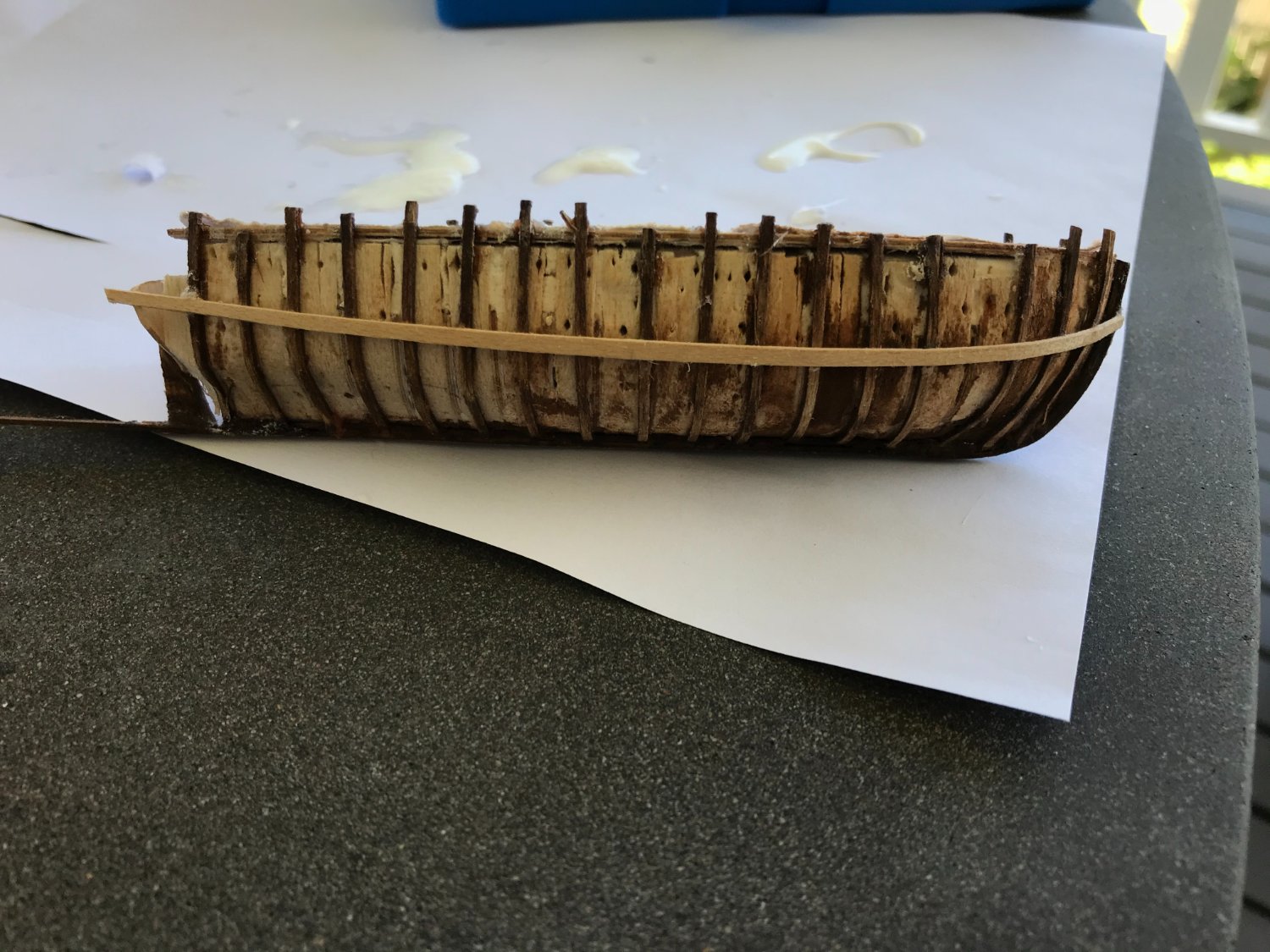
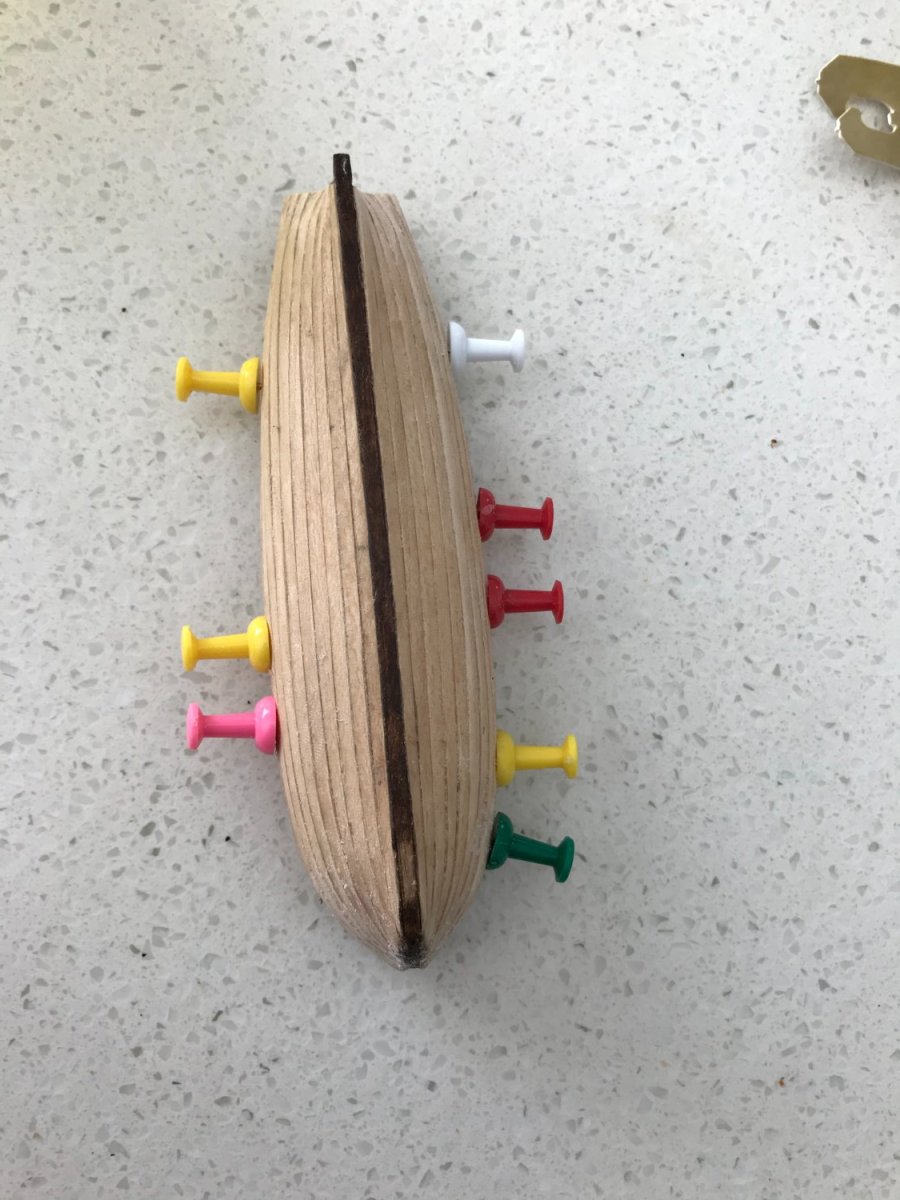
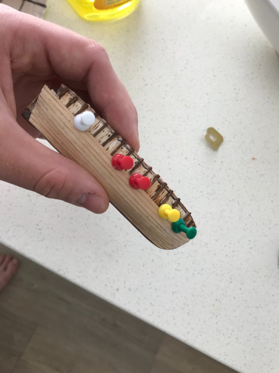
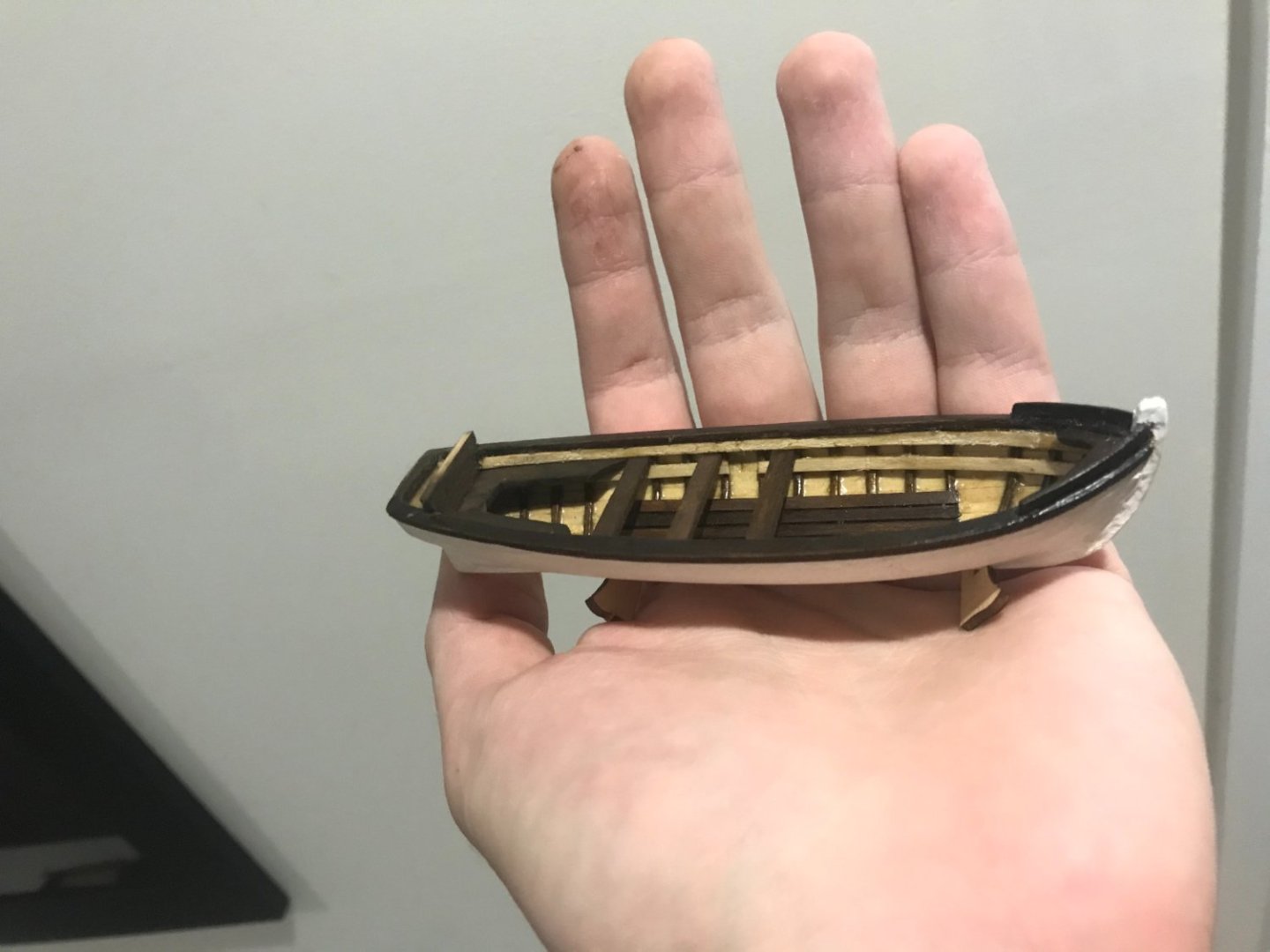
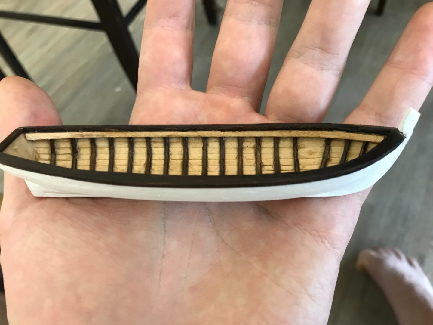
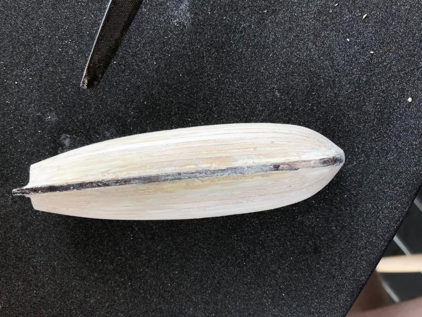
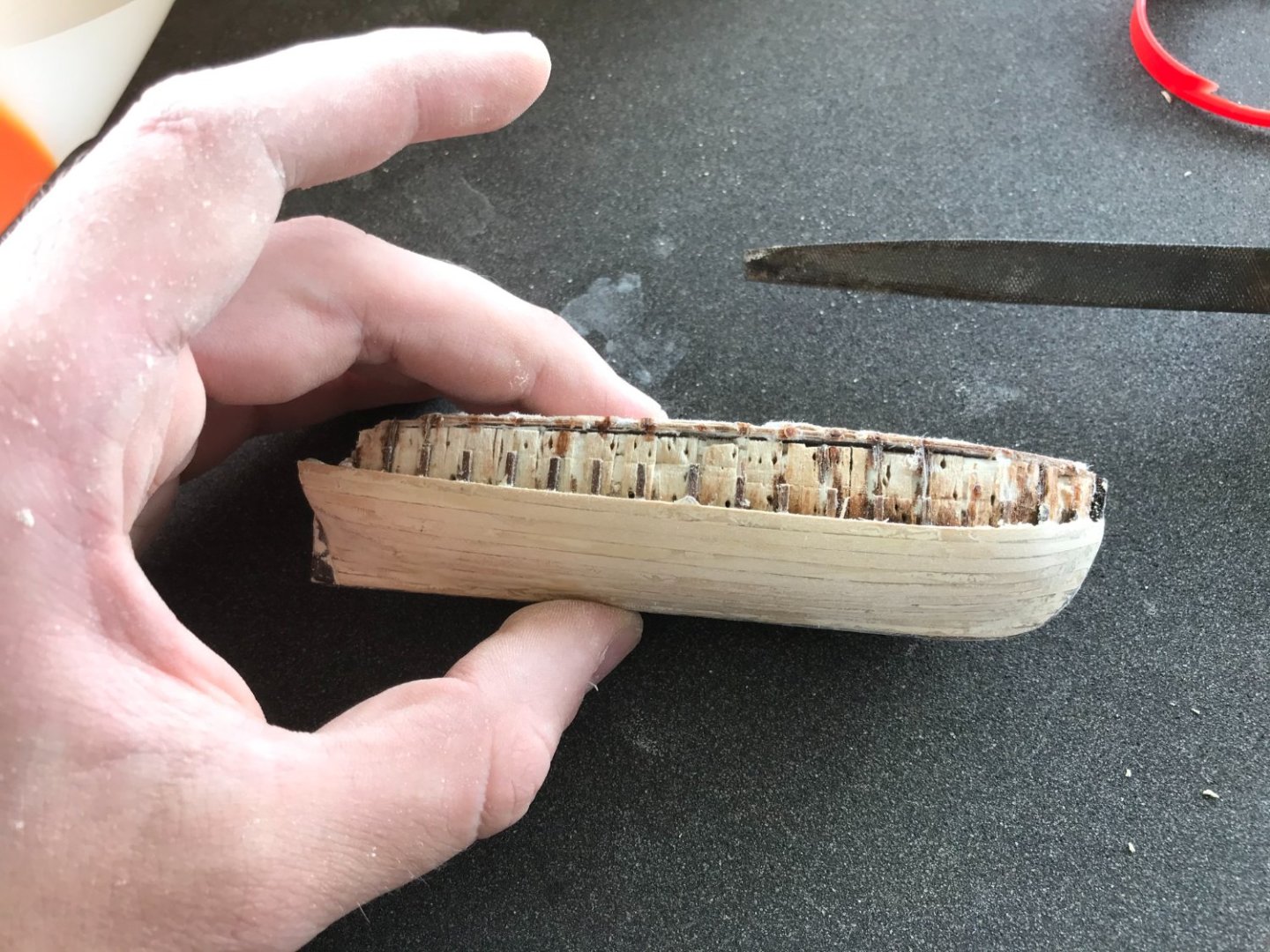
Hey everyone, I’ve been working on fitting out the hull of the yawl and making it look nice. I painted it and fit the sheer clamps to give it some more rigidity. I was a bit worried about it spilling out at the sides, as this happened on my first build the Bounty’s launch After fitting the gunwales it was much more sturdy. I cut these from a piece of ply after tracing the outline from the remnants of the jig. I cut them wider than they should be to start (around 4-5 mm width), and then sanded them down to fit the hull as best as possible to around 2-3 mm. They should be mirror images, but I did have to bend them a bit while gluing. Then some other bits and the deck planks (varnish is not quite dry yet. It was a bit fiddly to get the bow looking right I think the sheer clamp got a bit grubby by this stage, will try to clean it a bit. Really enjoying making this little guy and getting into it. I think I’ve gotten over the main barriers which were bending frames, planking and fitting the gunwales. Should be much easier to do boat number 2 (and 3-7) now.

-
Hi Rob, yeah it was definitely close! I’m not sure if this is the best way to go about it, I’ve seen other people use laser cut frames which might be a bit easier. This works for me though, even if it is pretty time consuming.
-
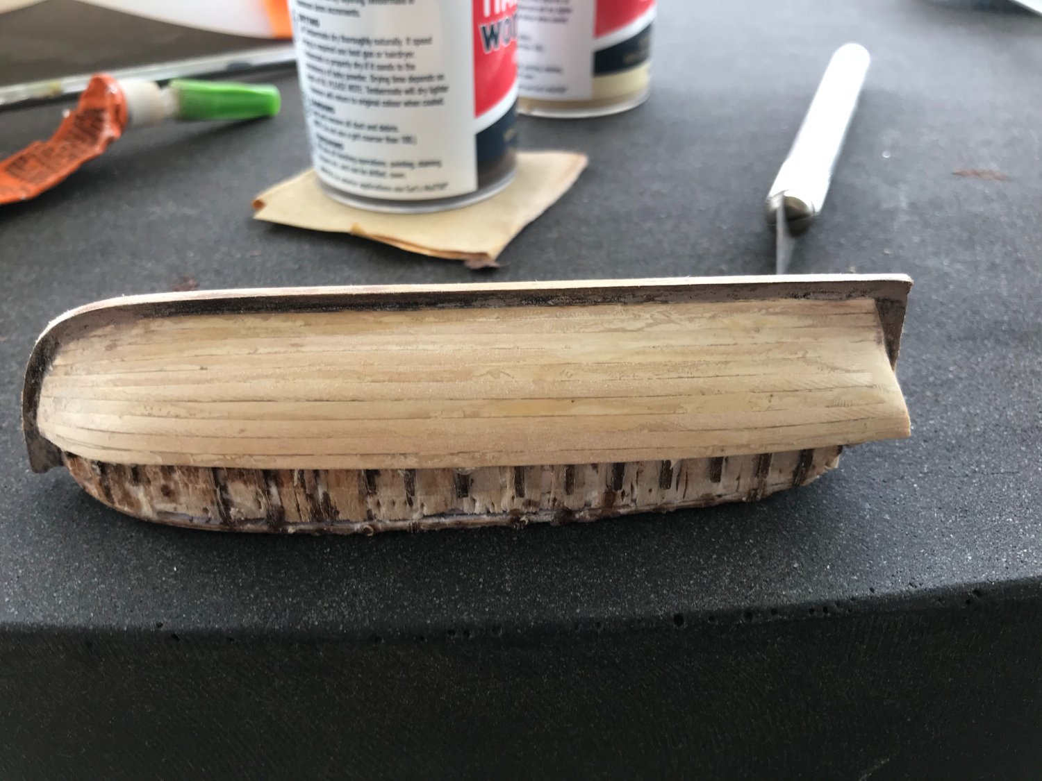
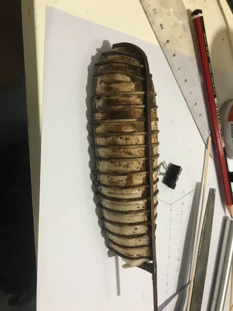
Just a quick update here, I fitted the final layer of the keel over the planked hull and started painting it. I got a little excited and tried to get the hull off the jig. I still have painting to do, but I was a little worried and wanted to see how it would go. It did not come out of the jig easily, definitely glad wrap it next time, I’m amazed nothing broke. The remnants of the jig are also attached.


-
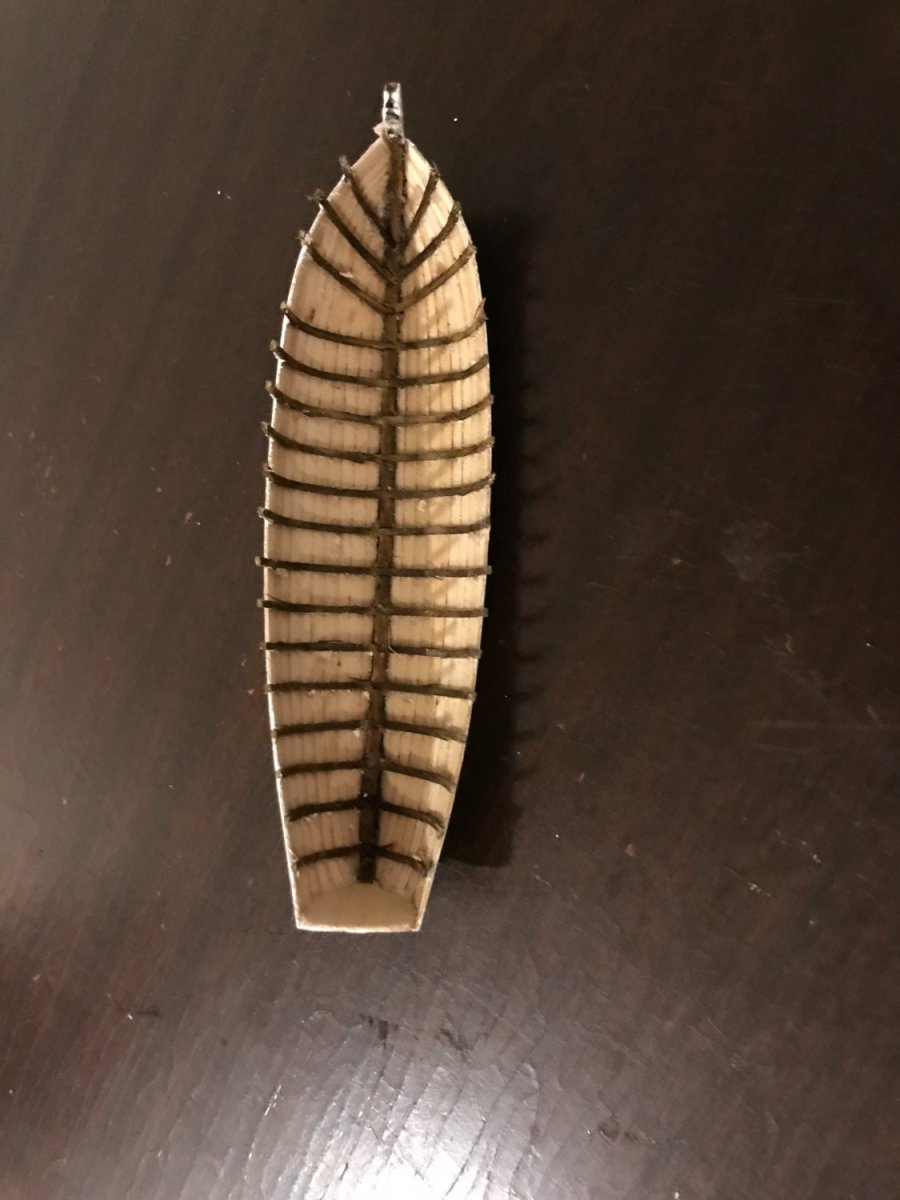
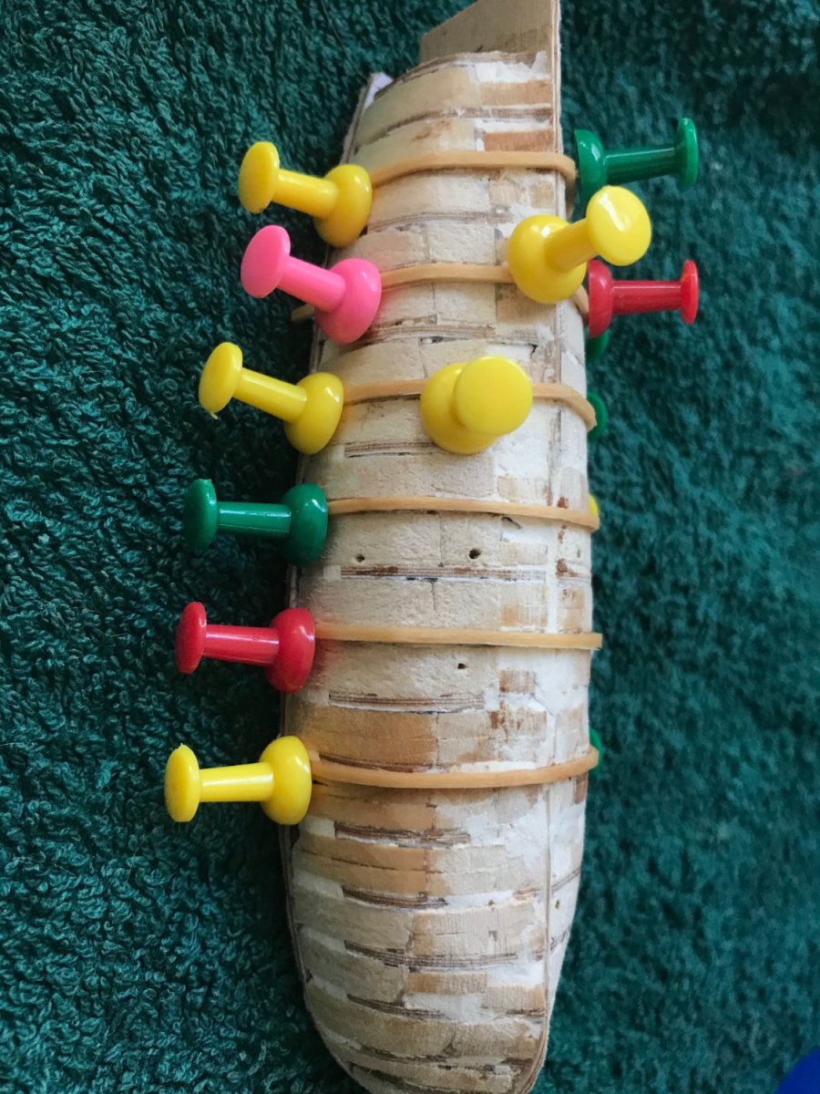
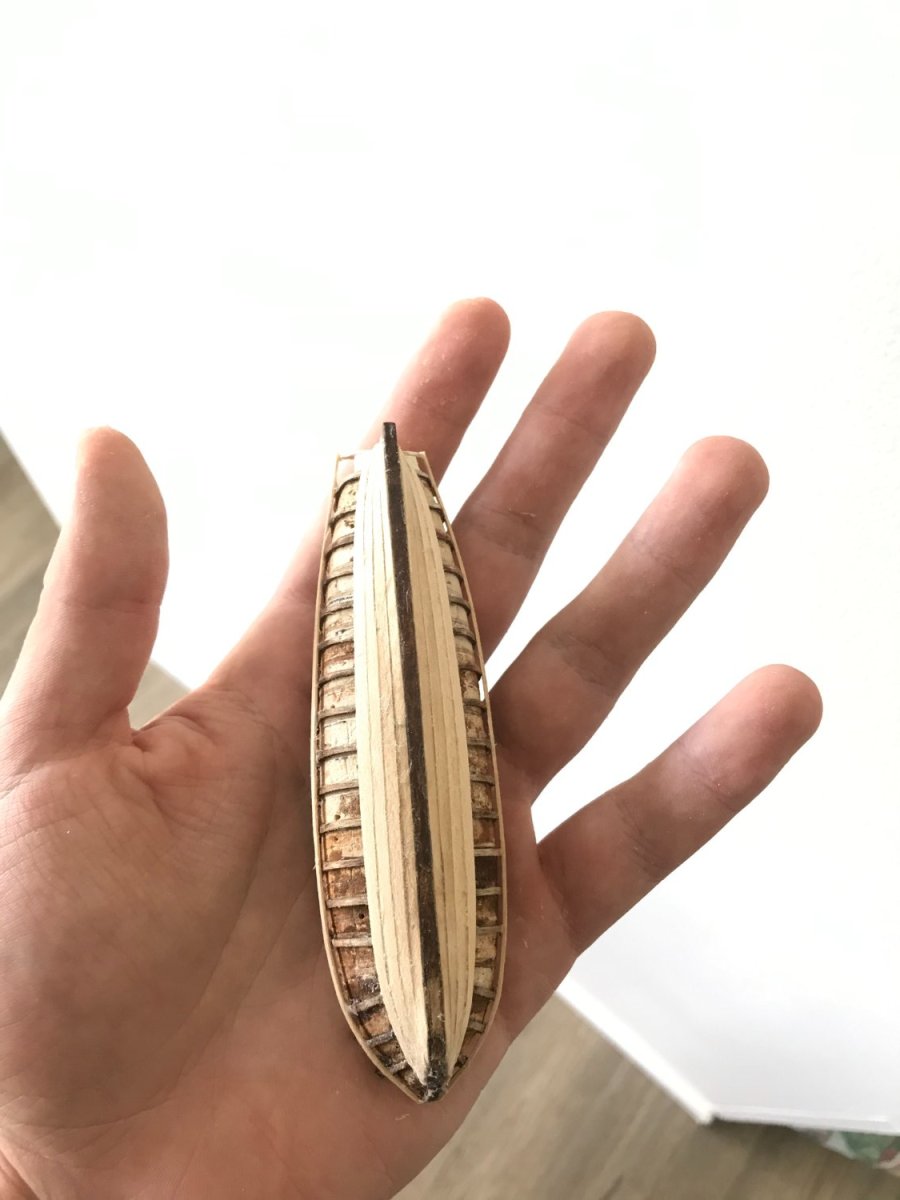
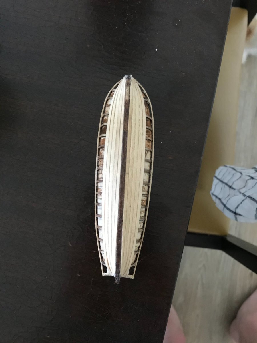
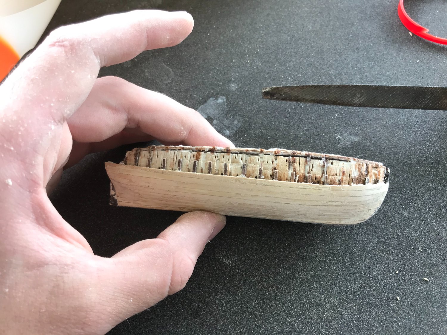
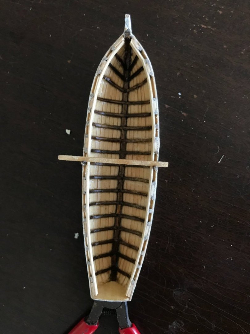
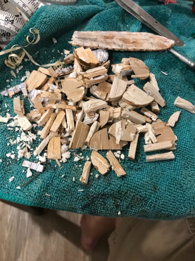
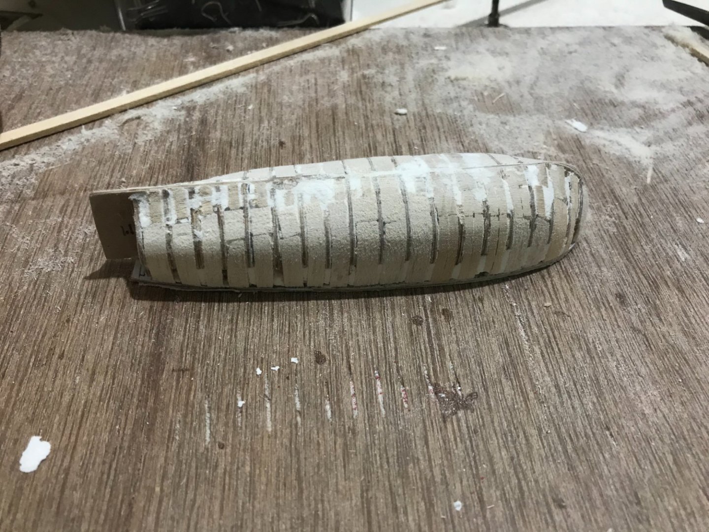
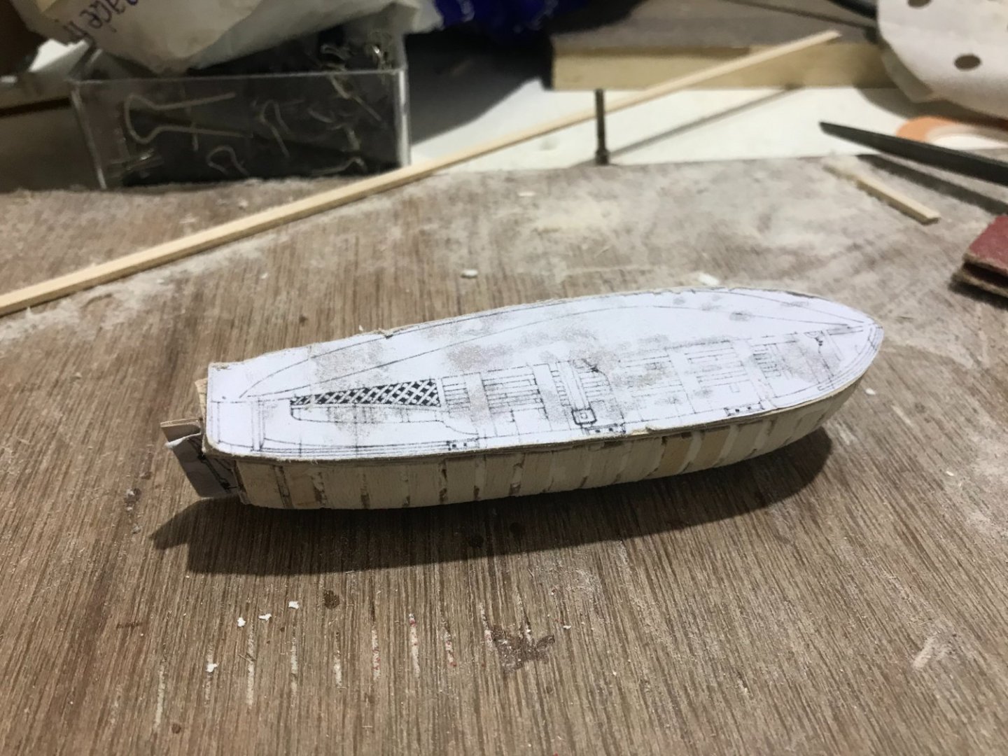
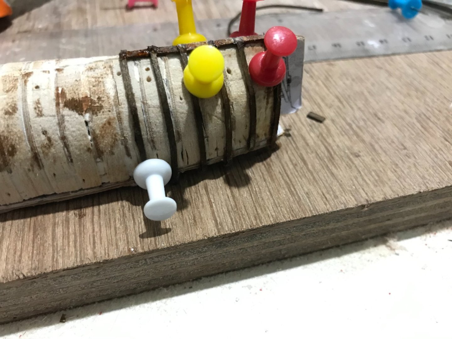
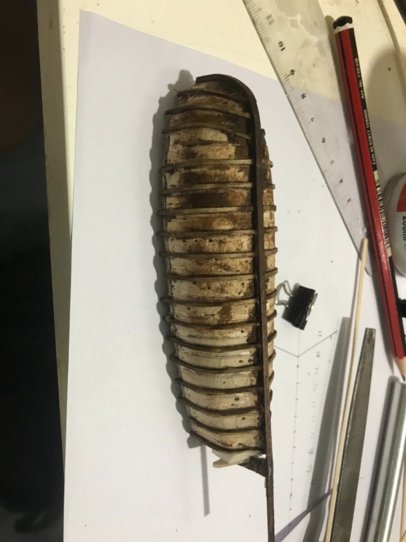
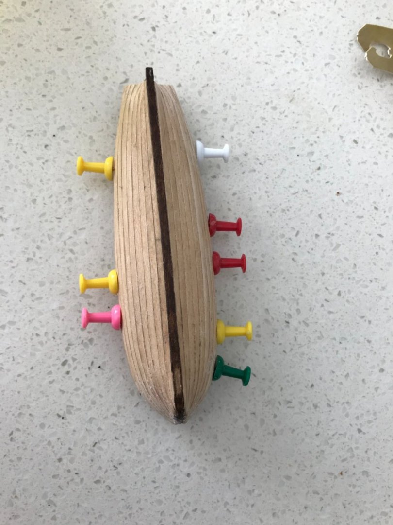
Hey everyone, so I have finally gotten around to planking the first boat, which is the 26 ft Yawl that sits in the centre of the main deck. I’ve used the anatomy of the ship to construct the jig. This involved printing out the body lines and using these as template to cut each piece of the jig out of 1.5 mm plywood. These were all fitted into a false keel and the space between them filled with balsa. I sanded them down to give a jig that closely approximates the body lines in anatomy of the ship. Then I used the jig to bend 1 mm sticks to shape to form the frames, I stained each of these with a dark oak stain. I glued each of these at the top with a spacer piece (I think it was 5 mm length and 0.5 mm thick). I hoped that this would prevent them from sticking to the jig, but in hindsight, I should have covered the jig in plastic to really prevent this. After fitting all the frames, I added another layer of the keel to hold them all in place, the planks would then meet the keel at this height. I also fitted the transom and sternpost and then did some fairing I figured I would lay the sheer plank first to get an idea of how much space I was working with. It was very difficult to measure these things accurately as the boat is so small and my equipment is not really precise enough. I ended up eyeballing a lot of it and hoping things were the correct length. I think I am extremely lucky that it worked out as well as it did. I did my planking from the garboard up. The logic was that if there were problems at the top, I could simply re-adjust the sheer plank to make it all nice. Fortunately, this was not necessary (it is such a little thing!) Then filling and sanding to give a nice finish (this will be painted white). This hull would have been double diagonal planked on the real ship. I was tempted to give this a try, however I figured that it would be a good idea to get practice planking on this one as I would want to hide much of the planks in the finish anyway (because it is inaccurate already). This would help me later when I try and do the remaining 6 boats, 5 of which are clinker planked. I guess we’ll see whether it comes off the jig...


-
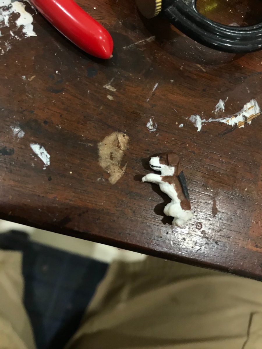
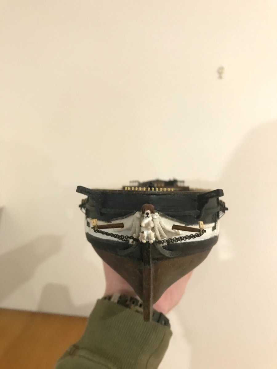
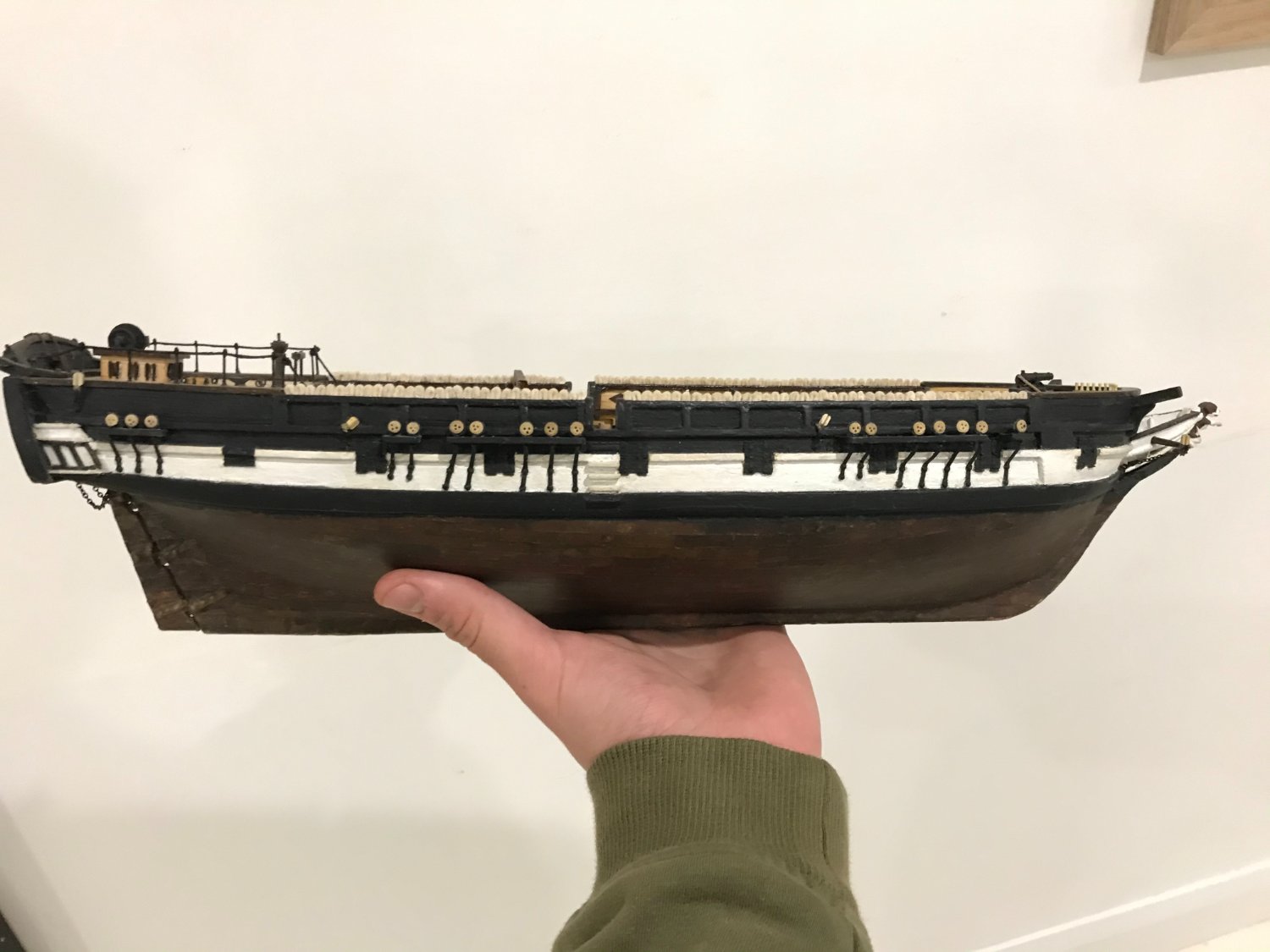
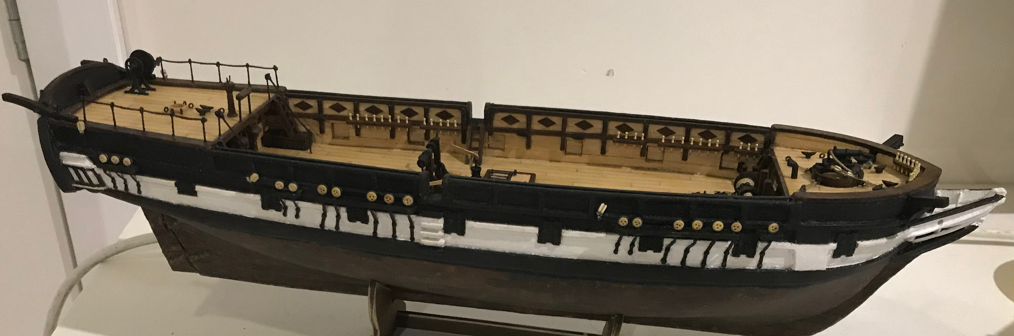
Hey everyone, so long time since my last post. I haven’t had a lot of time this year to work on the boat much, but I’ve been slowly working away at a few things. Part of it is time, but I also haven’t been able to give the proper head-space to the boat all that much. I've been very busy with my final year of uni, which is a research project that has been occupying a similar place in my brain that was previously occupied by the boat. Last post was about the cannons, they were tied down using some tiny blocks, but that I think look okay. I also painted the figurehead and did the prow details with some blackened chain Then it was finally time to actually do the hammocks. It took some trouble shooting, but eventually I did end up with a method that worked. Then it was just a slow process of repeating it 100 times. They are a bit random and rough, but I don’t mind that, as my key frustrations with the kit hammocks were the regularity, the missing fold lines and the fact that they were completely the wrong material. This was one of the three biggest changes I had been planning from the start of the build and been most apprehensive about so I’m really glad that this is done. Coppering was the first. The third big change is what has been causing considerably more difficulty, which is to scratch build all seven of the survey boats. At the moment, I am working on a jig for the frames and planking. I think I will post when that is done even if it is not very exciting


-
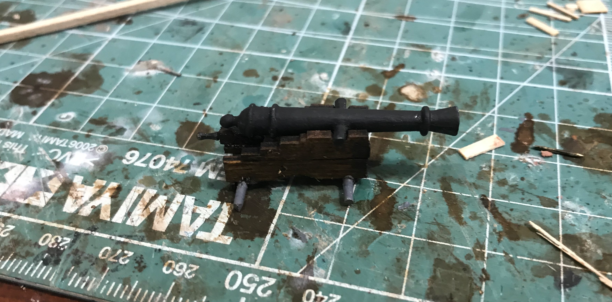
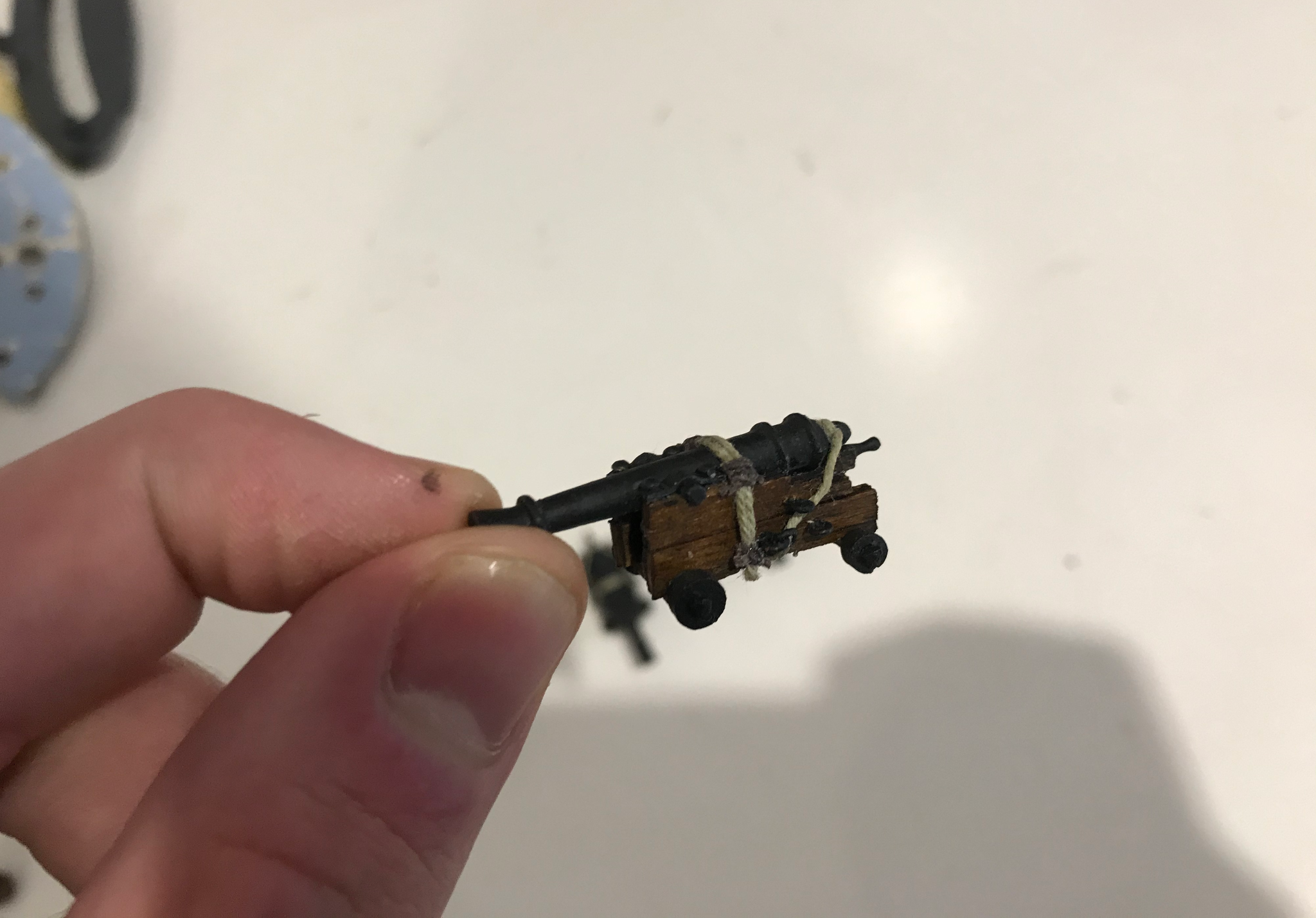
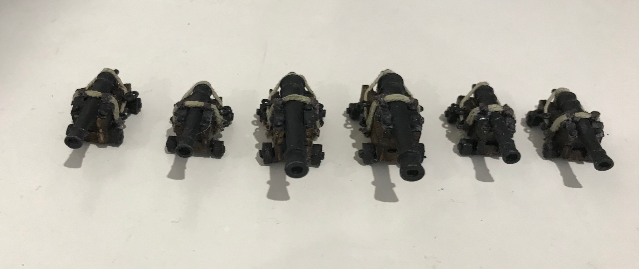
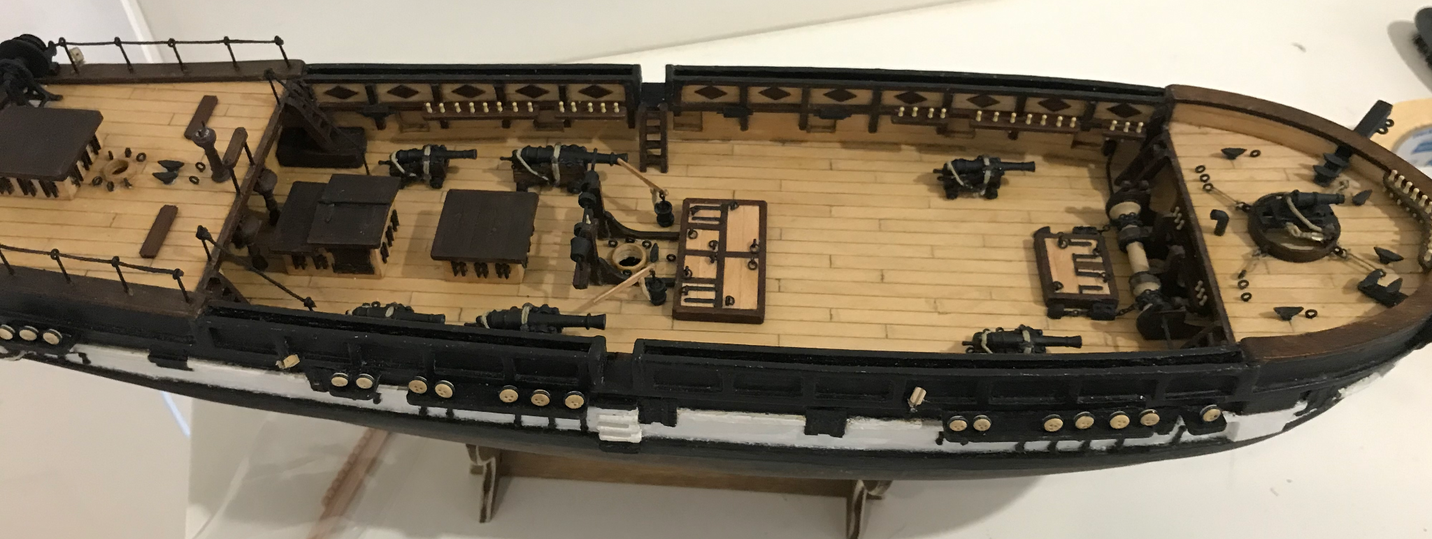
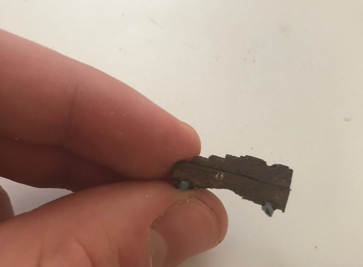
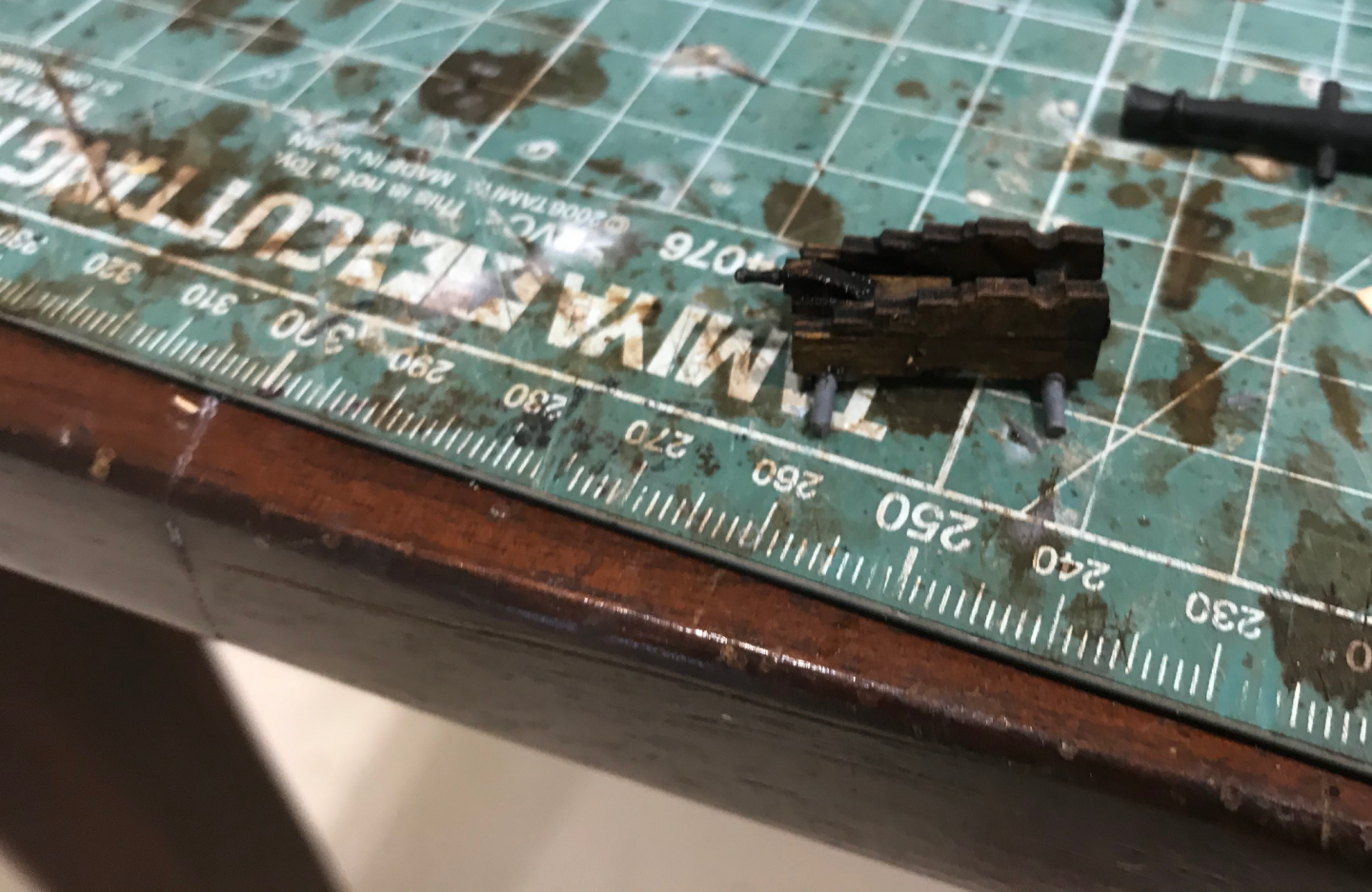
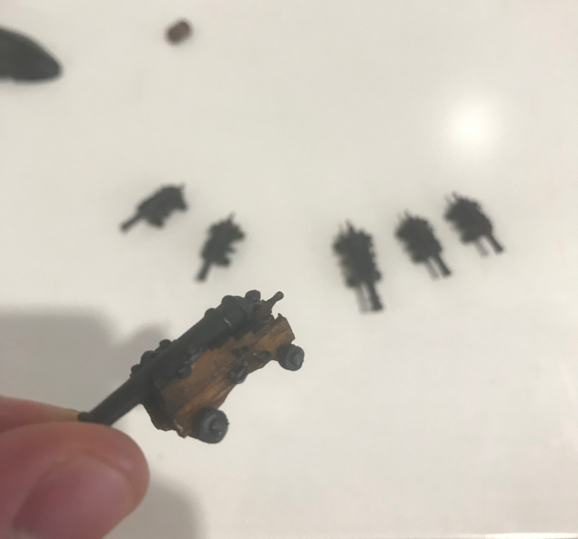
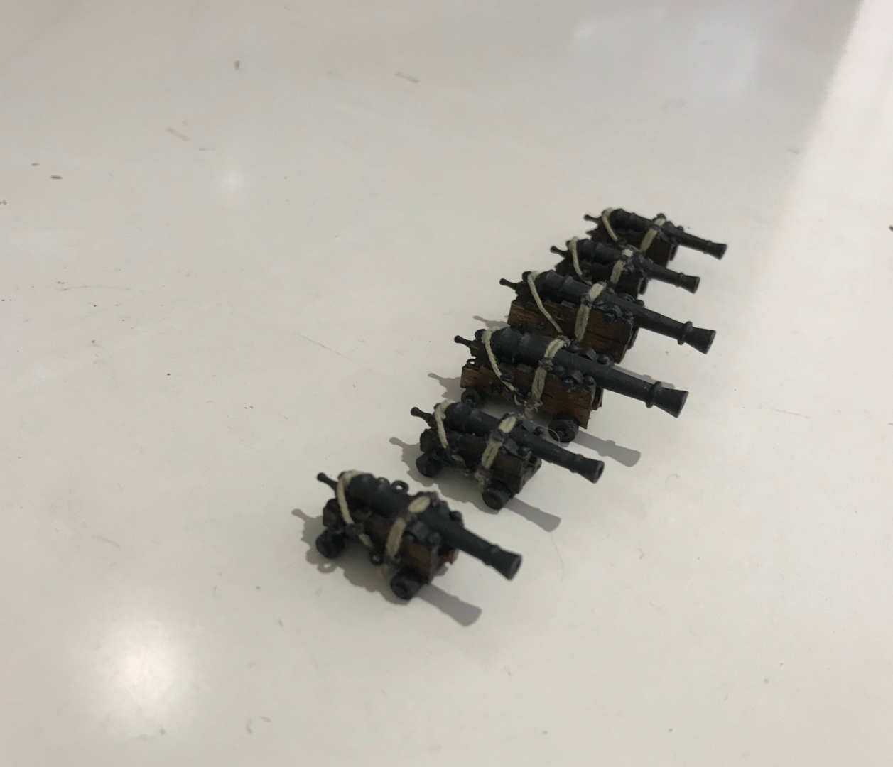
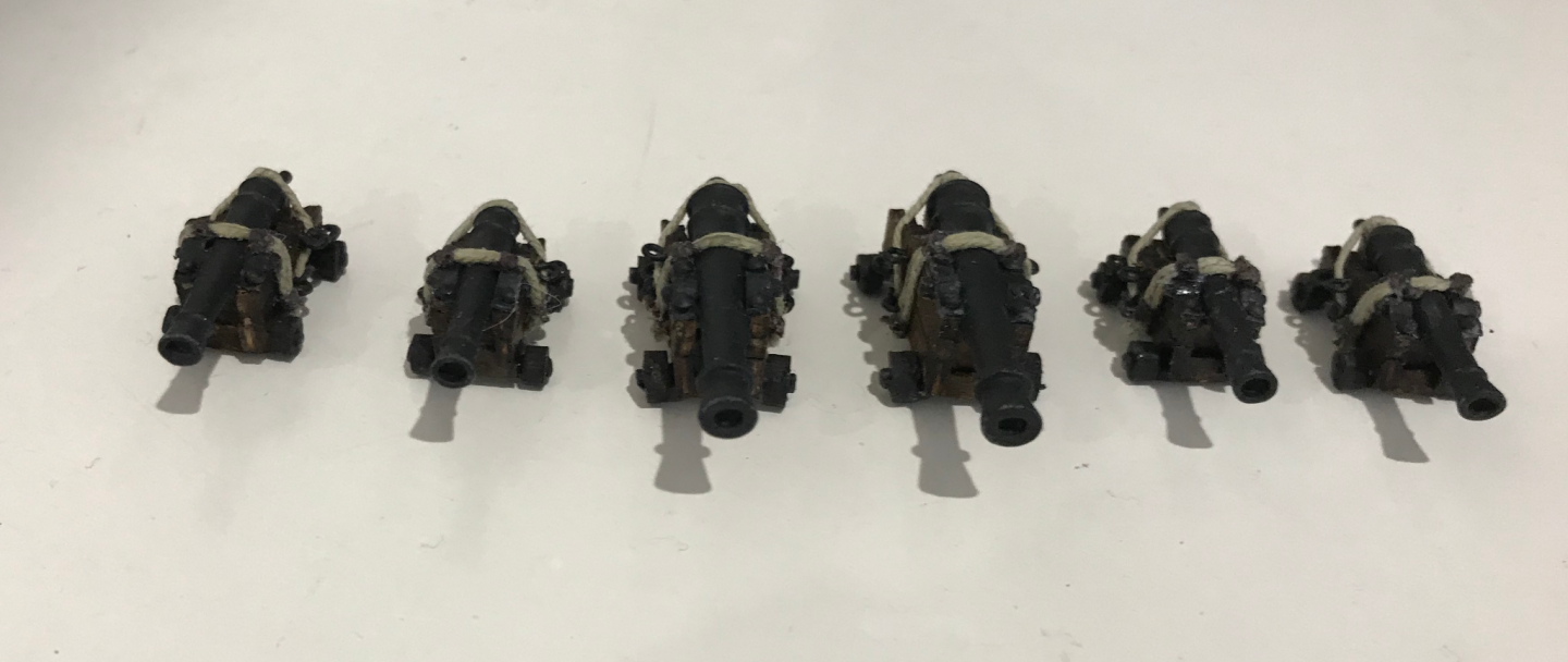
Cannons were also a fairly significant deviation from the kit instructions. Instead of using the laser cut parts which did not look right to me, I only cut off the top ridged bit of the side pieces and used that. The bottom section of the side piece was then glued to that to give a groove. I made up the quoin using the previously purchased brass belaying pins Then I could add the actual cannon barrel (yay) The main body of the cannon was finished off with wheels, eyebolts (from 0.5 mm wire) and cannon hinges. This all had multiple steps that took quite a while with 6 cannons. I can’t even imagine doing 100 for something like the Victory, but I would definitely want to do a big battle ship like that eventually. I also rigged them with some 0.5 mm thread. I now need to add the blocks and tie them down to the deck. I think I will also add eyebolts to each of the gunports where the cannons are supposed to go. Anyway, here are some more pictures.


-
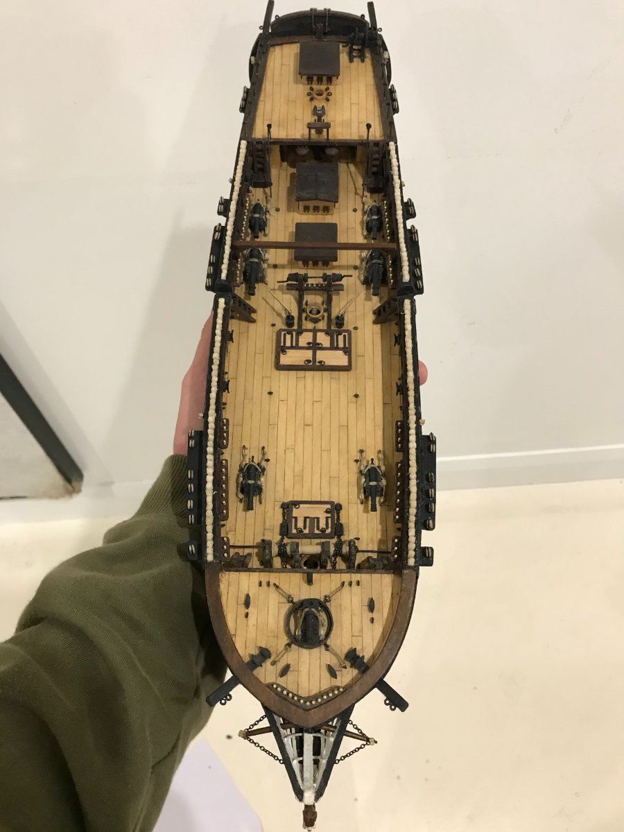
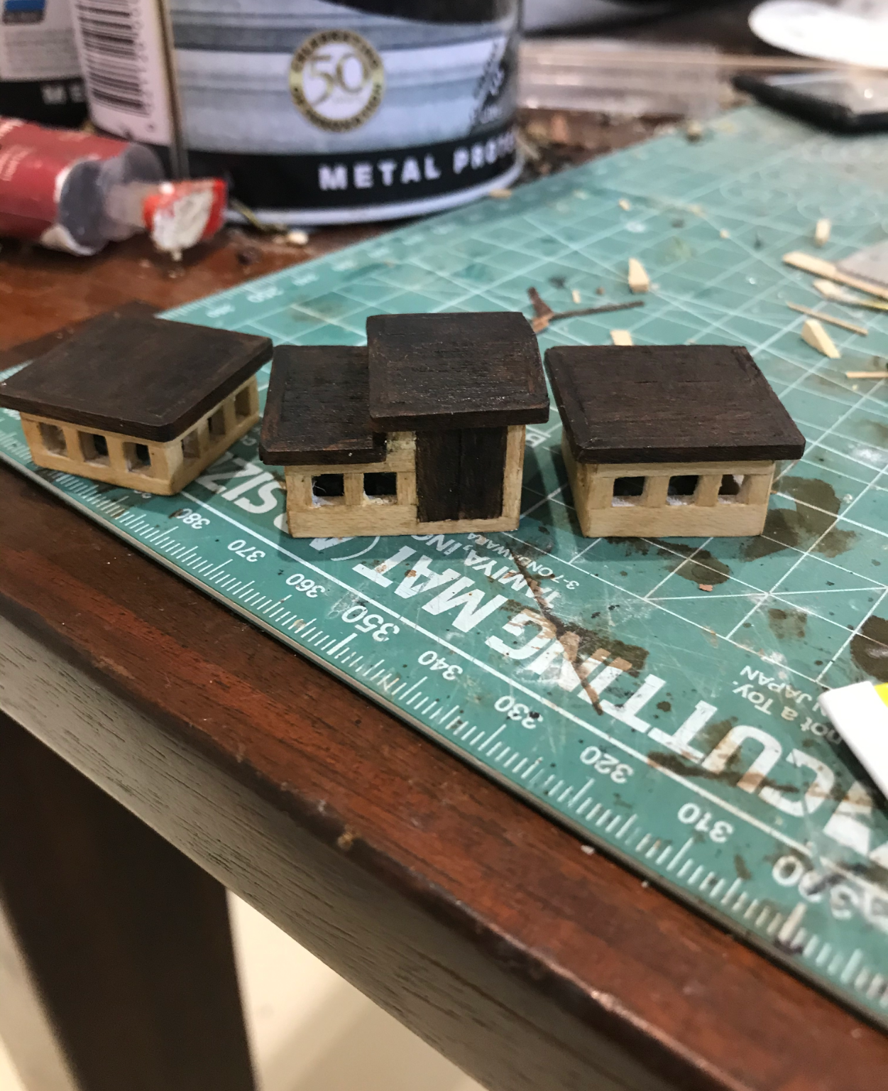
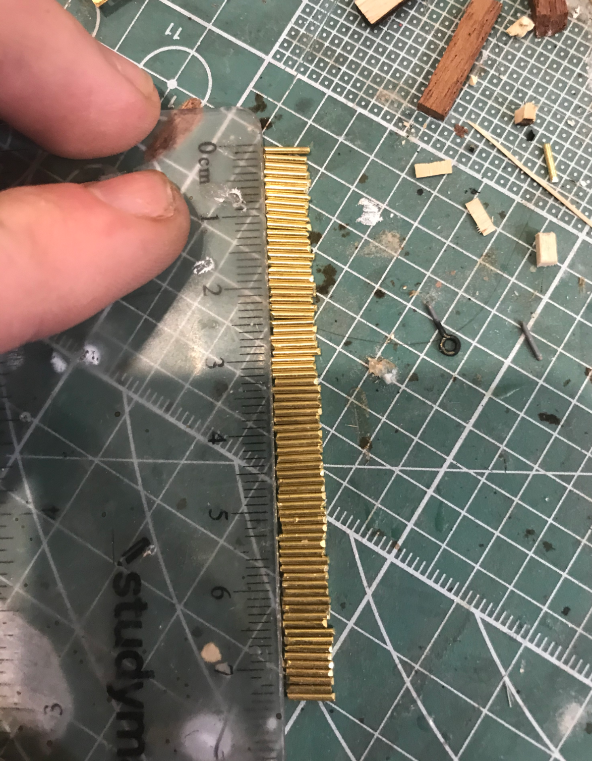
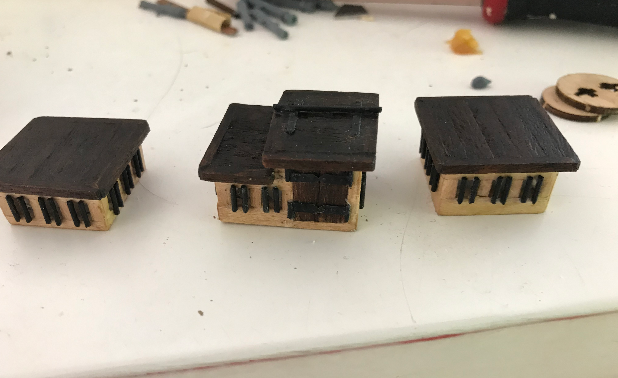
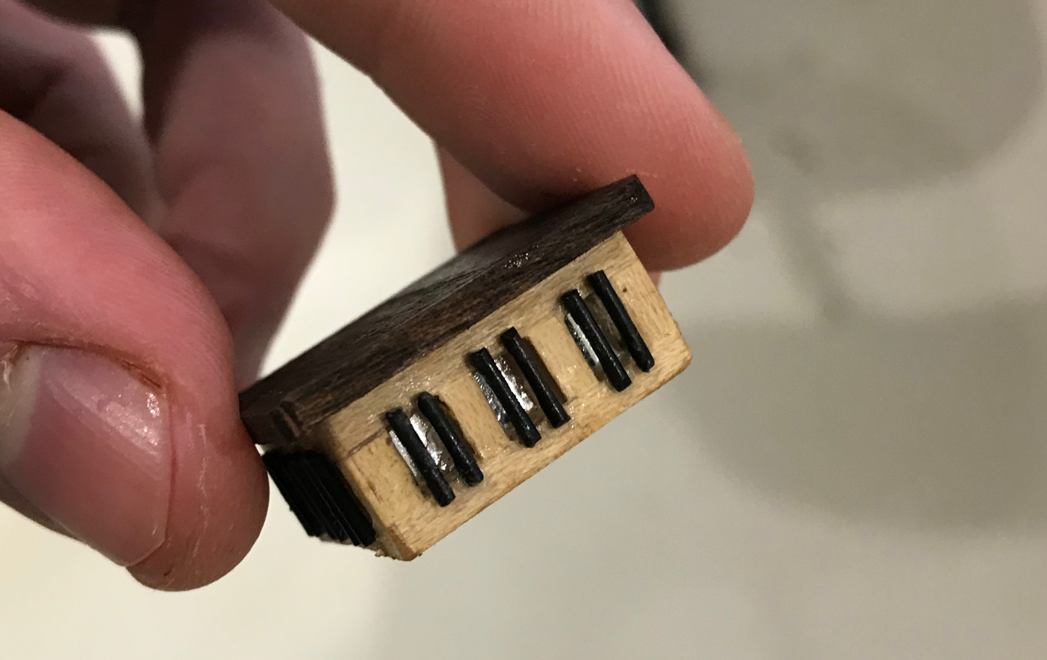
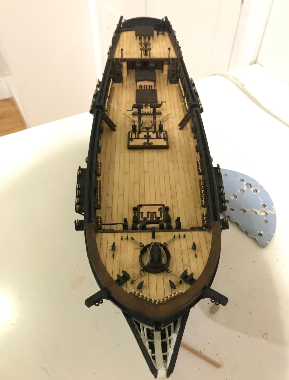
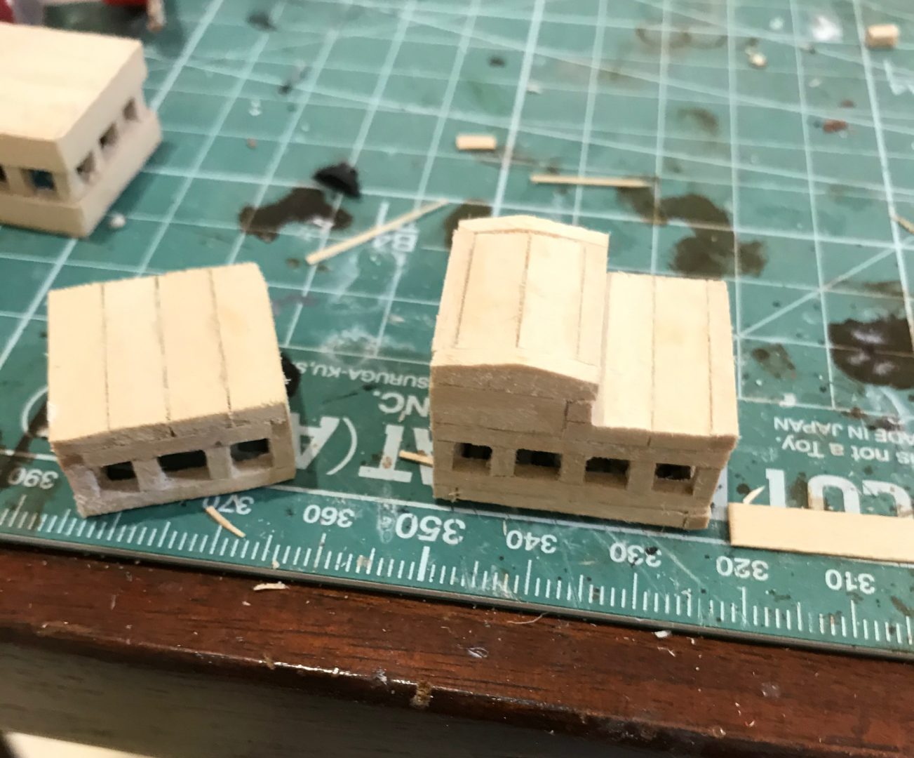
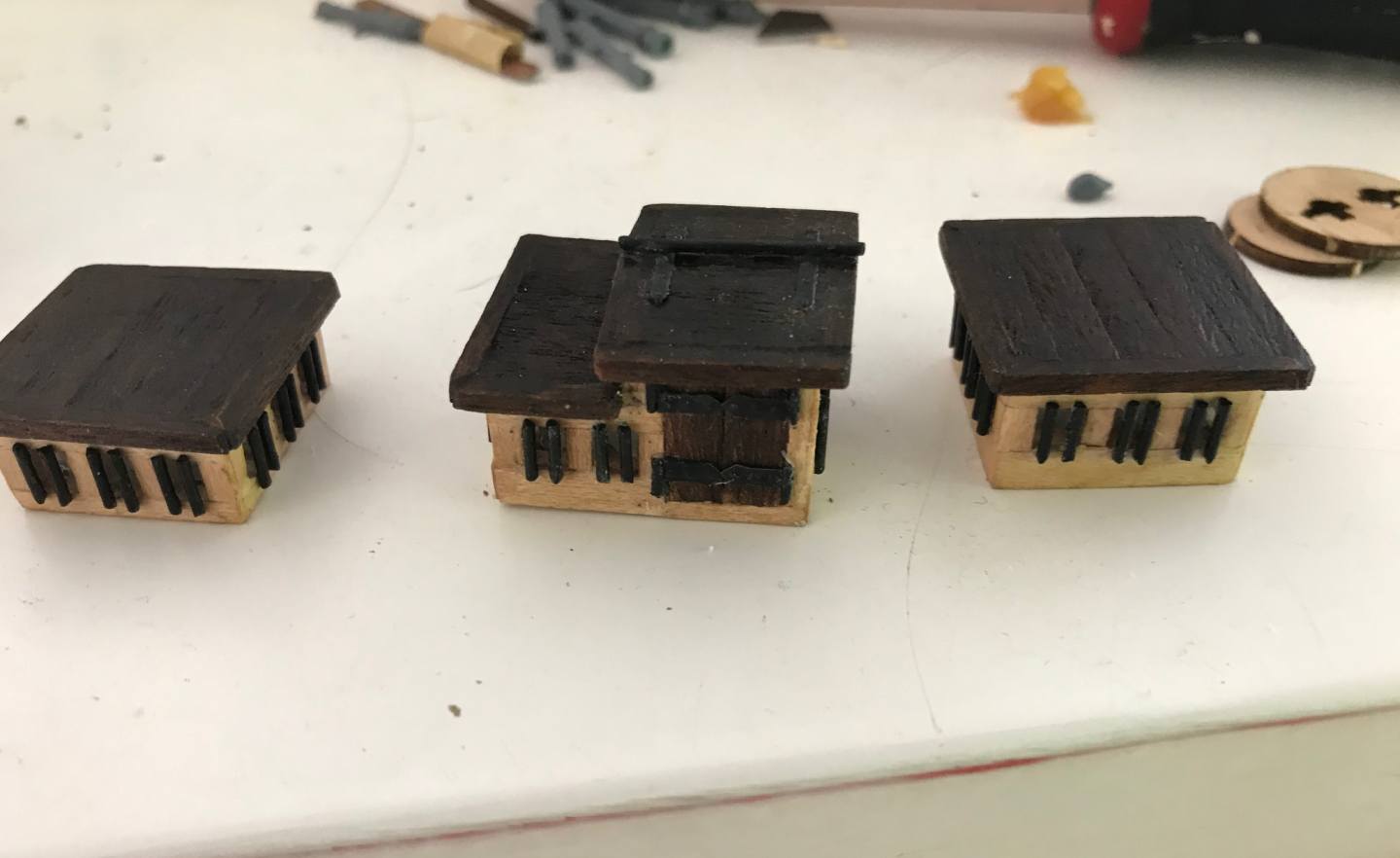
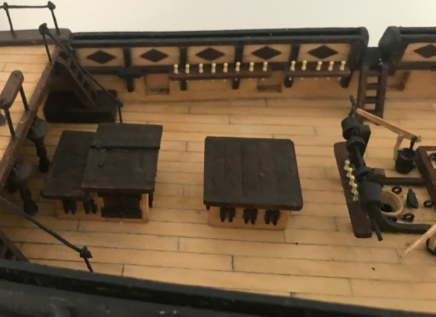
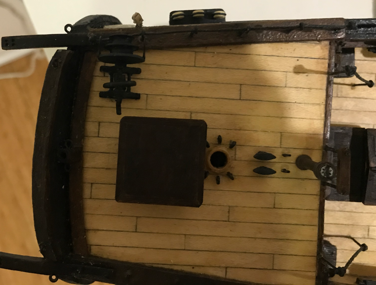
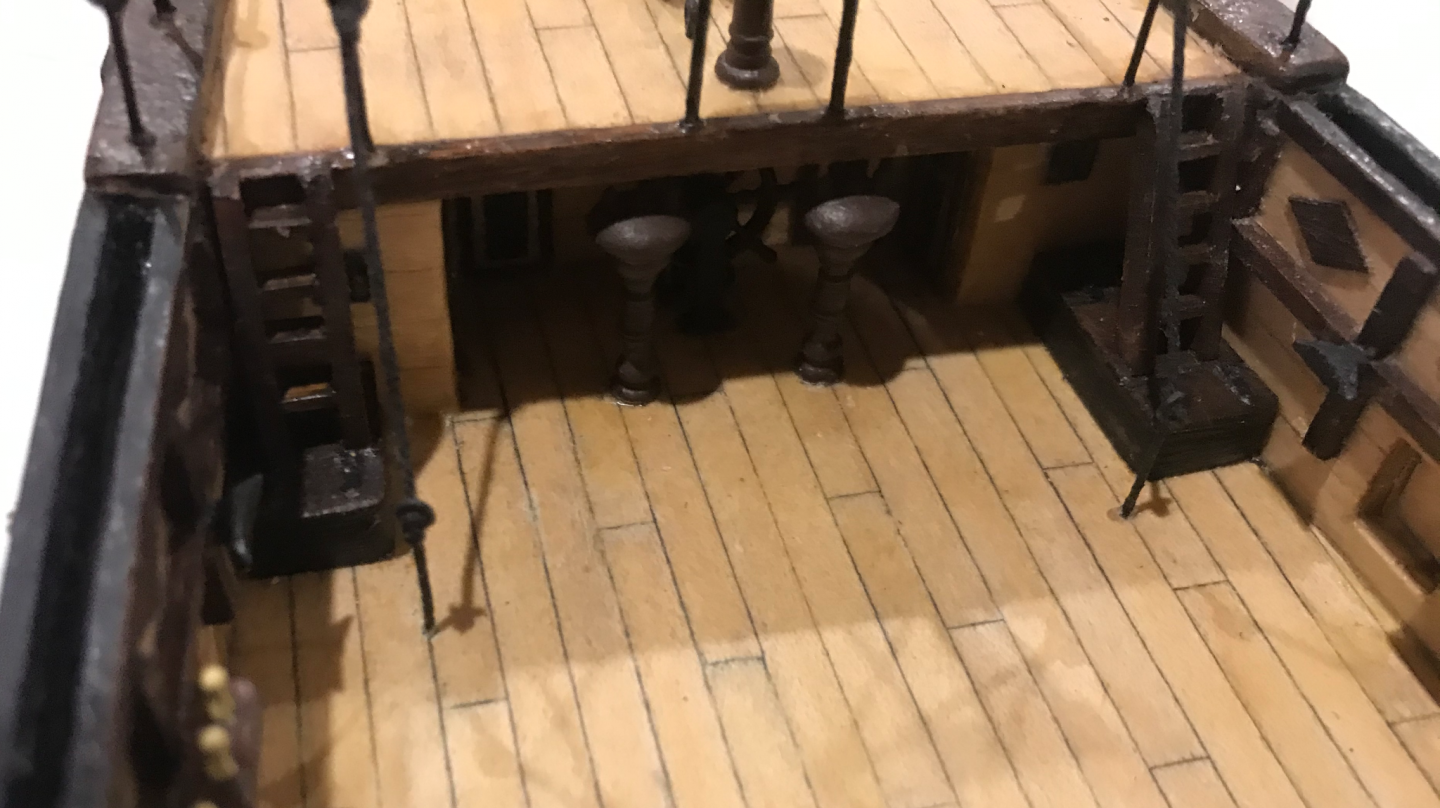
Similar to how I did the cabin windows, I wanted to cut holes in the wood and place a mirror behind it to give the illusion of depth. This proved quite difficult with the pre-cut parts as cutting out the holes was extremely painful and they ended up being too small. So instead, I decided to scratch build them using some of the limewood pieces. This gave some ugly little skeletons here (I think the main one is wrong here, I fixed it later but the slope on the roof should go the other way) They looked a bit better with the sycamore lining and the roofs I had to also make the bars from scratch, which was a long night cutting 1mm brass rods (I ended up buying some spare stuff in the end) I really did not feel like priming all of these and then painting them multiple times, so I decided to blacken them instead, which turned out okay Then I glued in the mirrors to give this effect, which is quite difficult to take photos of Then I fixed them to the boat, and the deck was starting to come together There was a bit of trouble on the poop deck as the sounding winch did clash a little with the larger sky light and I had to rebuild it with shorter wire and shift it a bit so that there was enough clearance (I think this piece is a little too large for scale, but I still like it) Anyway, cannons next.


-
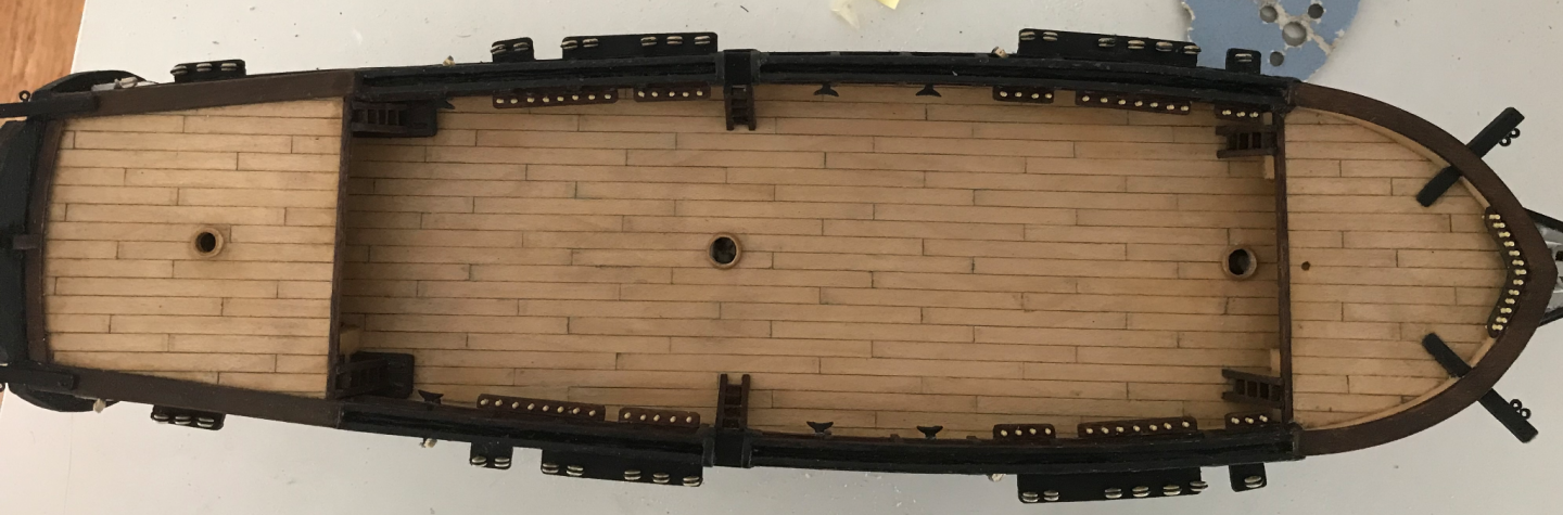
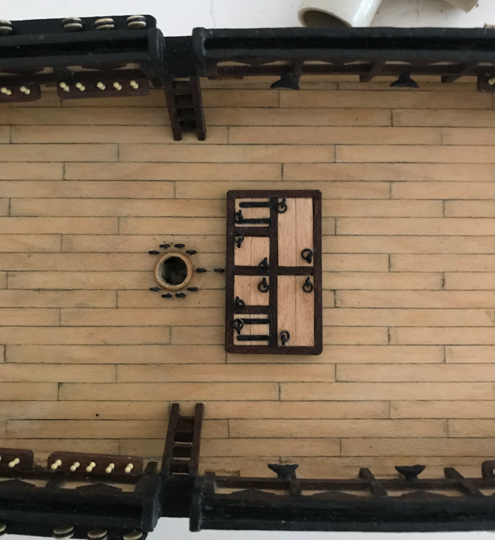
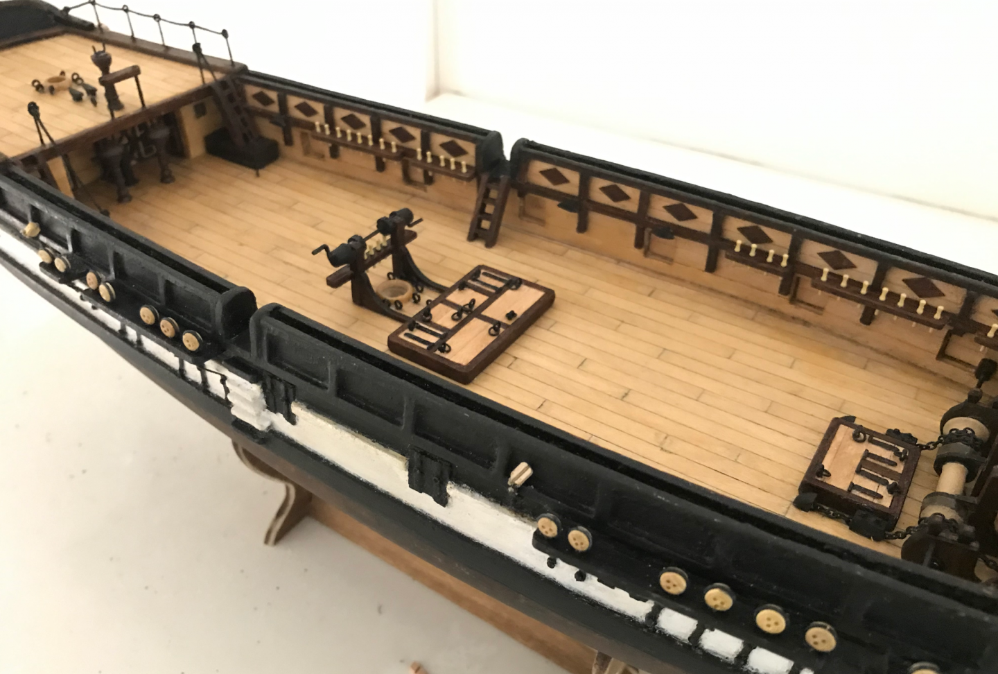
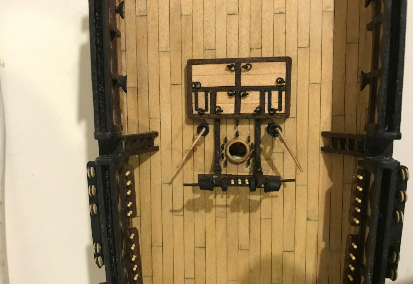
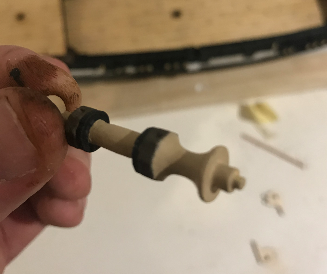
Hey everyone, I’ve been quiet for a while but have a couple of posts that have been ready for a while now. It’s been slow going for the past couple of months, but significant progress has been made since the last update and I have a few posts I can do now. First up is all the details around the main mast. The hatchway was mostly straightforward to make. I had a bit of trouble with the number of eyebolts around the main mast. I settled on 6 around the mast and one in front (changed after this photo). I did also need to order some more cleats as I think the rigging in the OcCre guide is not quite accurate. I’ve forgotten the specificities of what each of the eyebolts are for, but I’ll get into that later. The winch was a little tricky. I added some gears by cutting a thin wheel off of a dowel and cutting in some grooves to mimic the effect, which I think works. I also had to make the posts a little longer as it clashed with the belaying pins Bilge pumps were fiddly, but mostly straightforward, getting them to align symmetrically took a bit of trial and error but turned out okay. The sounding winch was also fun. For ages I could not figure out what this thing was for. This was apparently used to lower ropes to the sea surface in order to gauge the depth of the sea floor, which is pretty cool. Then it was either cannons or skylights. I had planned some pretty major deviations for both of these and both seemed a bit daunting. In the end, I decided to do sky lights first to get all the stuff that is actually fixed to the deck done first.


-
Understanding Truss Pendants and other rigging things
LucienL replied to LucienL's topic in Masting, rigging and sails
Hey Henry, I was hoping that would be the case, but wasn't sure if there was something I was missing. Looking at it again, it does seem like they've only included some of the rigging for one side, so you're probably right. That does put me more at ease, thank you. -
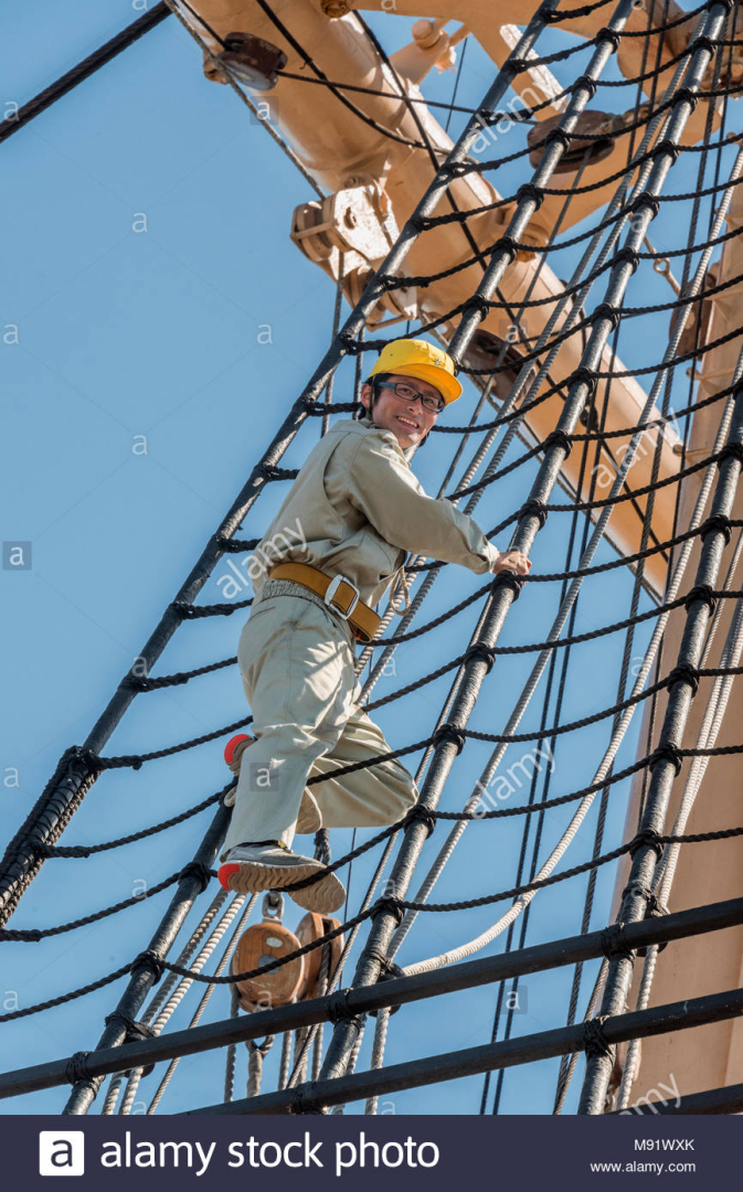
I don't know what the normal distance is, but AOTS has the same number as the OcCre plans, which would come out to 24 cm in real life and 4 mm on the model. This man is about as tall as 8 ratlines, but it's difficult to tell with the angles and the way he is holding on, but that would be equivalent to 7 x 24 or 168 cm, which is possibly accurate, but there might be more spacing here. If you went with 5 mm, he'd be 210 cm tall, so somewhere in the range of 4-5 mm is probably right. I'd say 4 mm would be decent spacing, but you might want to measure yourself and see how many ratlines you can fit given the length of your shrouds. Also, from when I did ratlines on my last ship, it might help to do the top one and the bottom one first so they end up being the same height on both sides of the mast. I ended up messing up the spacing a bit and one side was slightly higher even though they had the same number of ratlines.
-
Understanding Truss Pendants and other rigging things
LucienL replied to LucienL's topic in Masting, rigging and sails
Okay, thanks Allan, that's making a little more sense. In the Monfeld drawing, would there be two sets of tackle, and would this be a similar situation for the Beagle diagram? The reason why I ask, is I'm trying to figure out how many eyebolts I need to have at the base of each mast for each line that is attached to tackle, I know of two for the topgallant and royal yard ties. There are another two for the topsail yard (although they don't tie off at the mast base according to AOTS), one for the flag halyard and then one or two sets of truss tackle. There are also some stays that tie off at the base of the mast (one mizzen at the main mast and two main stays at the foremast) -
Understanding Truss Pendants and other rigging things
LucienL replied to LucienL's topic in Masting, rigging and sails
Ah, I'm thinking now that I may have got the purpose of the truss all wrong. Is it just to let the yard move away from the mast? If so, the dangling pendant still bothers me. If the yard were blown too far with the port side forward, would the pendant be at risk of slipping out of the block? Also, how would you then bring it back if you can only tighten the starboard side? -
Looking great. You've got ratlines just ahead of you, one of the most painful and rewarding parts of building the ship.
-
Understanding Truss Pendants and other rigging things
LucienL replied to LucienL's topic in Masting, rigging and sails
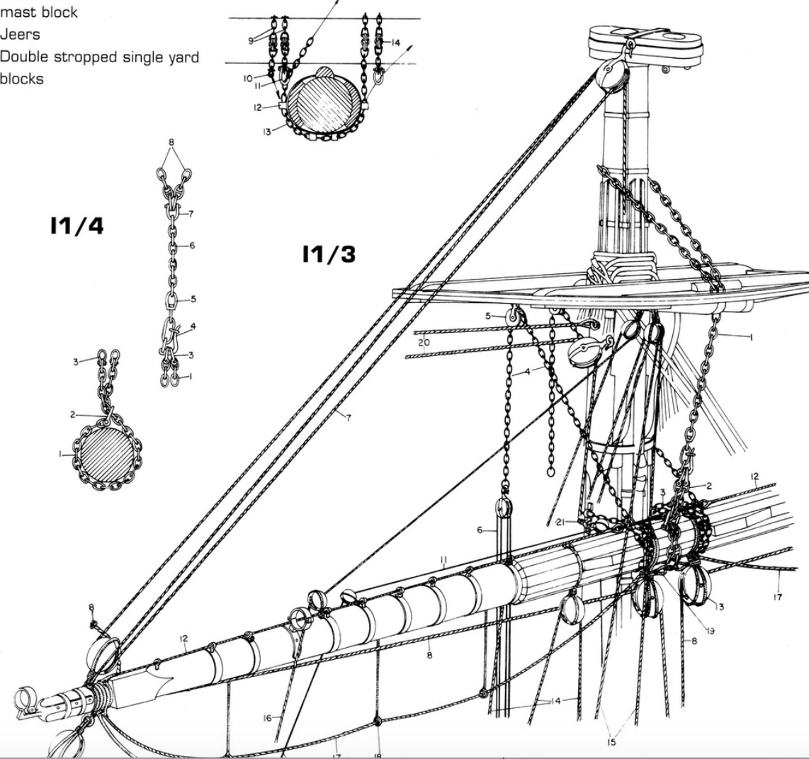
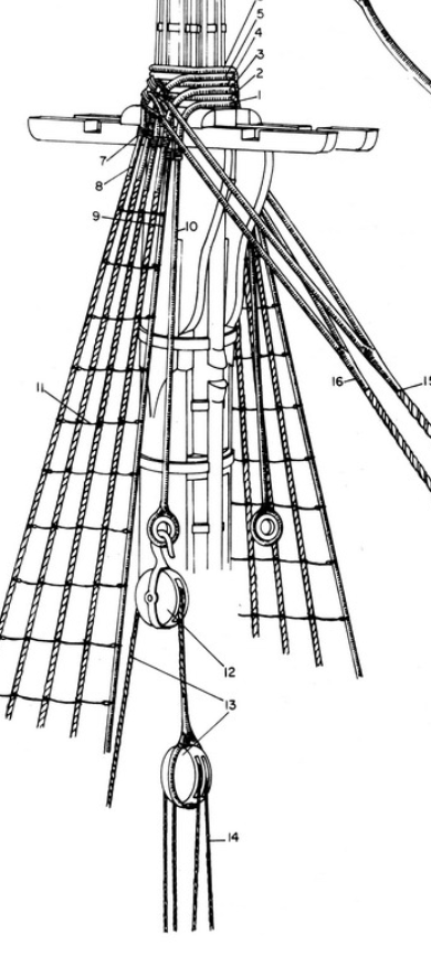
Hi Allan I think Anatomy of the Ship's plans come from a description of the rigging used for the Beagle by Robert Fitzroy around the time of the second voyage (1831). Admittedly, the quote is a little vague The Beagle was rigged with extra-strong crosstrees and heavier rigging “than is usual in a vessel of her tonnage. Chains were used where found to answer and in no place was a block or sheave allowed which did not admit the proper rope or chain freely.... Our ropes, sails and spars were the best that could be procured.” It may be some speculation on the part of the author (Marquadt) but there is at least some evidence. I can't really think of anywhere else chain would need to pass through a block, but my understanding of rigging is extremely limited and I may not have studied the plans enough. But my understanding of how the pendant actually worked is still unclear. Did the pendant really just hang there? I somehow have an easier time imagining that the Burton and mast tackles would just dangle as they were used to hoist up heavy items (I'm assuming that would be the lower yards?) If my understanding of the truss is correct, tightening the truss tackle would pull the yard one way and giving it some slack would let it fall the other way. This explanation seems unsatisfying to me as if the truss were loosened, wouldn't the yard be free to fall in either direction? Should there be another set of truss tackle on the other pendant? These diagrams were posted in another thread. The one on the right makes more sense to me than the one on the left. I'm imagining that there is a set of tackle for each rope at the deck in the right diagram and they can be loosened or tightened to turn the yards one way or the other. The right one is more similar to AOTS, but makes less sense, it also does not have a dangling truss pendant though...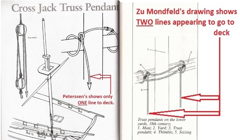
-
Hi everyone, I'm working on the HMS Beagle and basing my build off of the Anatomy of the Ship to modify the OcCre kit. Apparently, the Beagle used a significant amount of chain in its rigging, including for the truss around the lower yard. This diagram is included Looking at image I1/3, I'm not sure I'm fully understanding what's going on. The truss pendants are number 4 and the truss tackle is number 6. Would the truss pendant really simply dangle like this? If the truss tackle were to be tightened too much, wouldn't the truss pendant slide out of the iron block and suddenly become useless? How many ropes should be going down to deck regarding the truss, is it just one for the truss tackle or should there be another set of tackle on the other pendant? Also I have similar questions about the mast tackle pendant (is there a difference between mast tackle and burton tackle?) Any help is greatly appreciated.
-
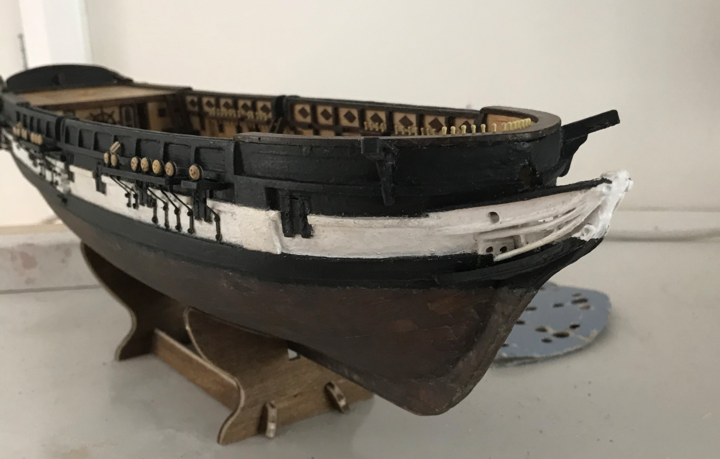
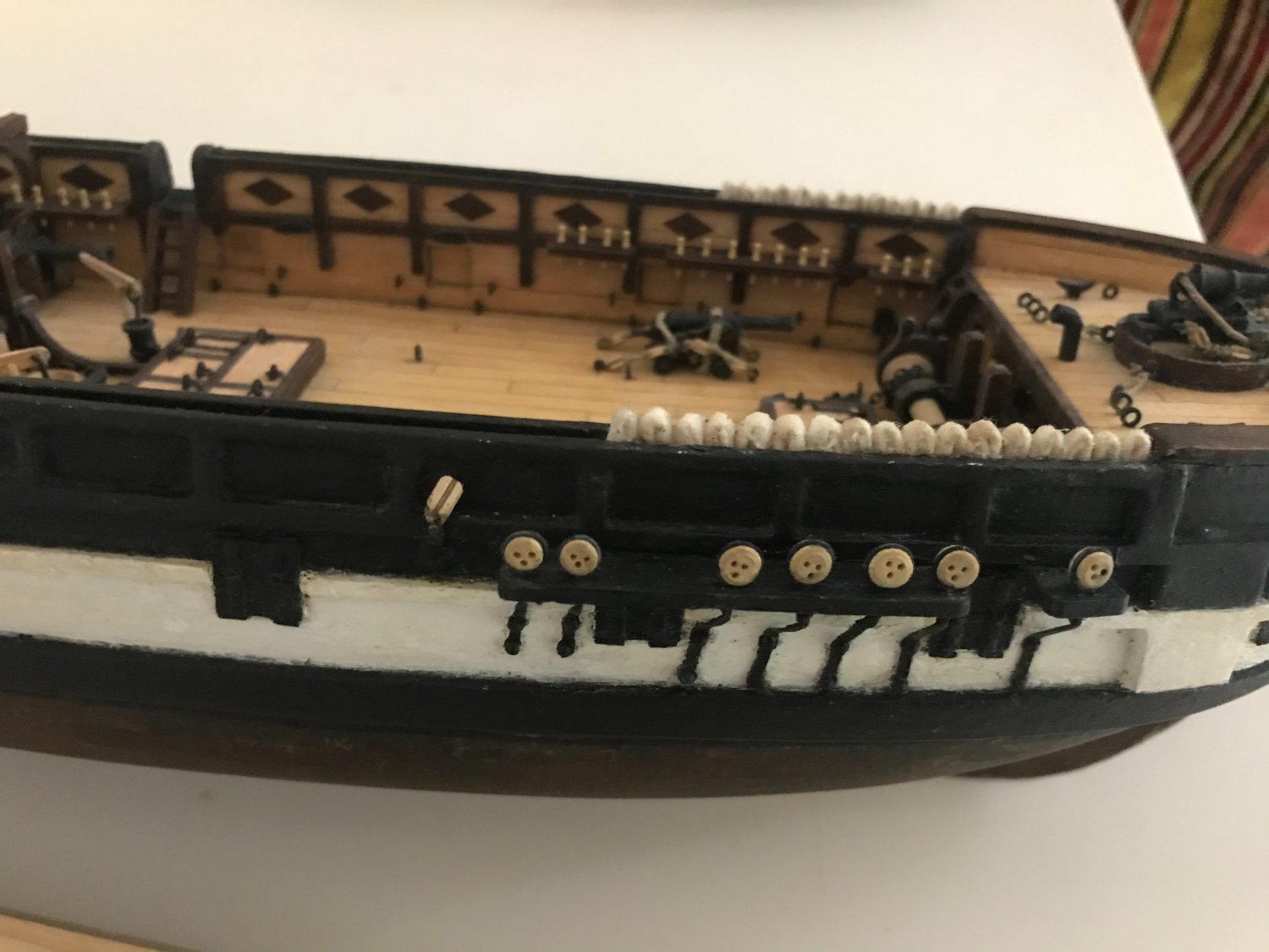
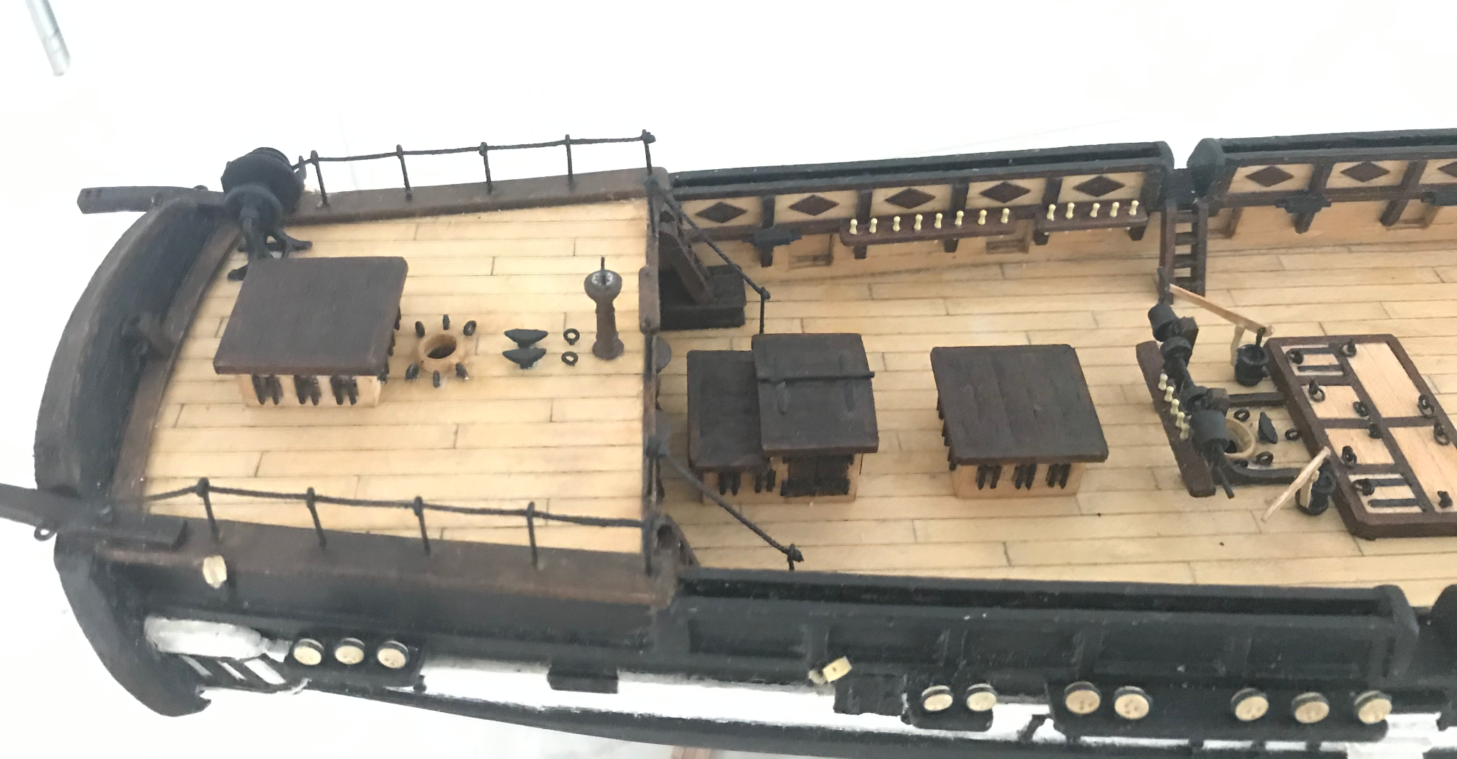
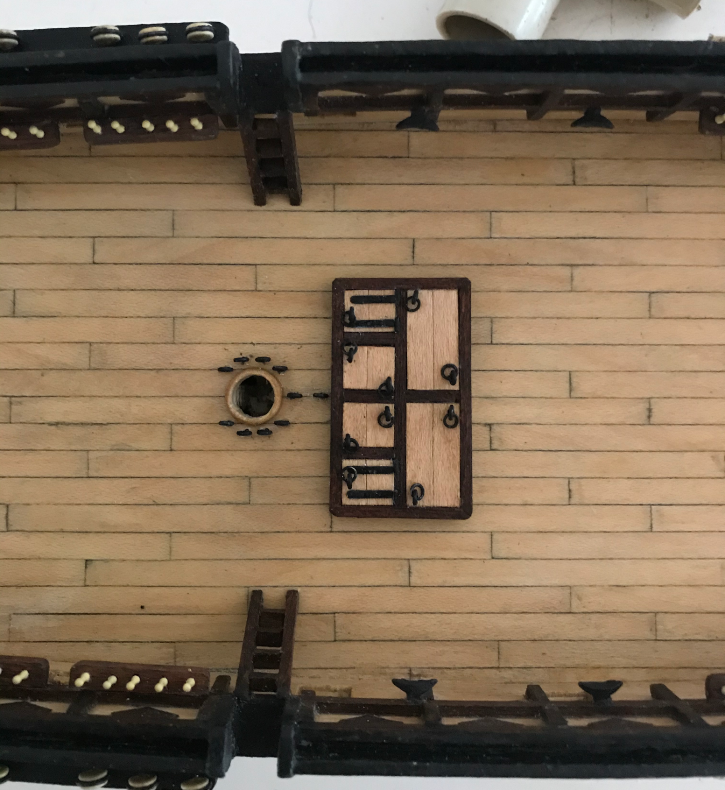
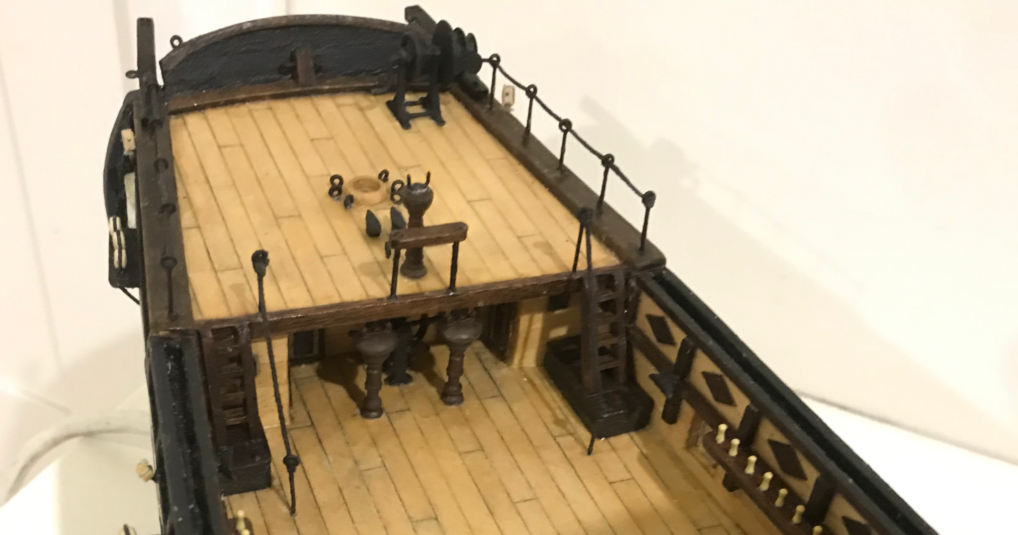
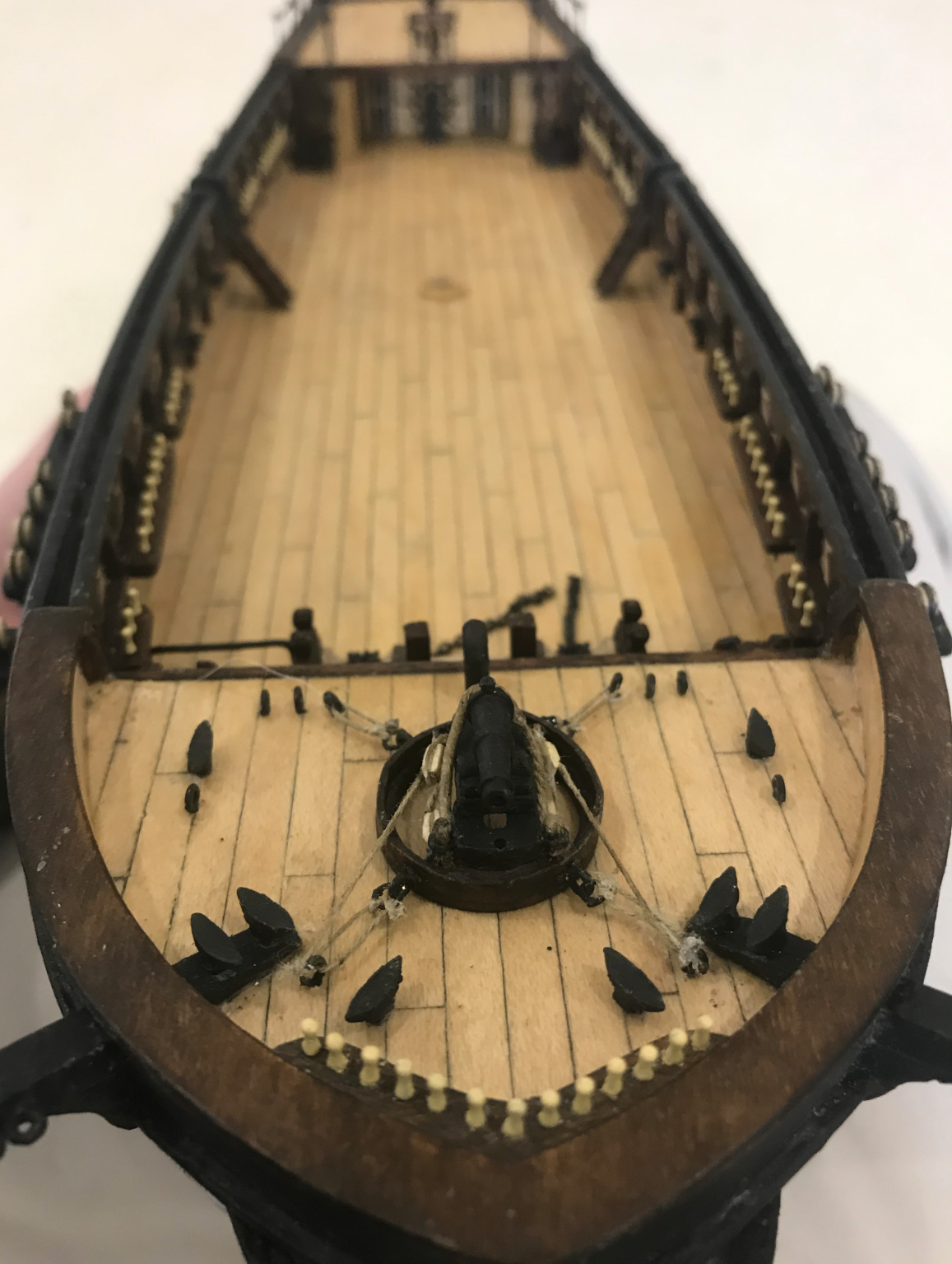
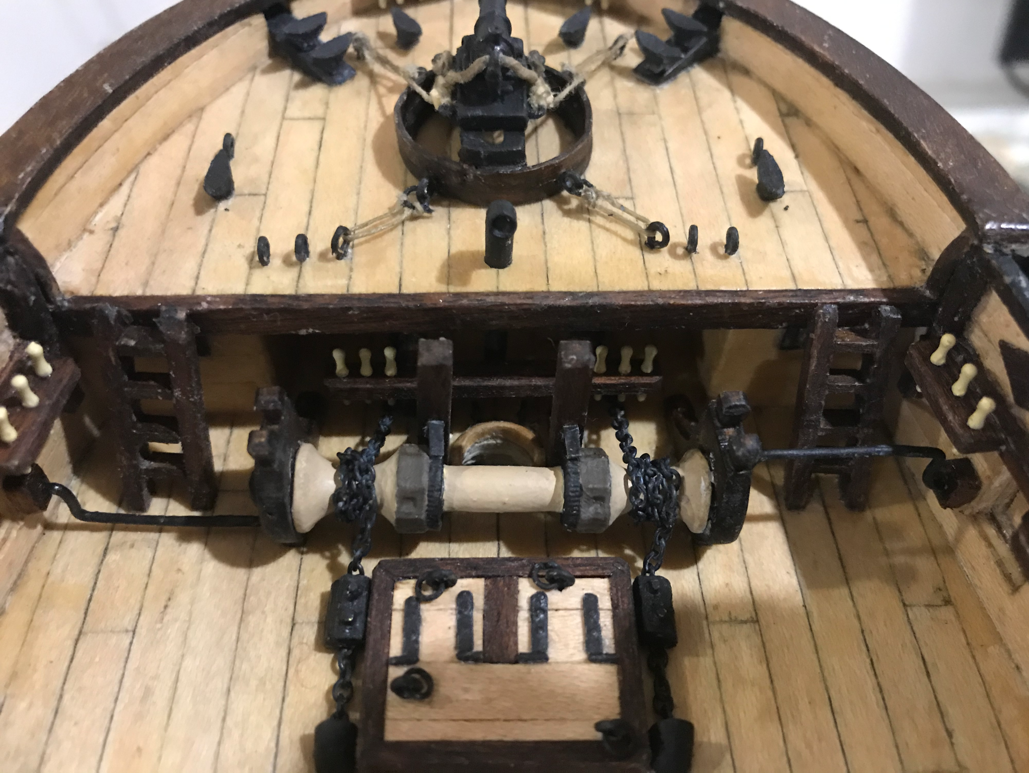
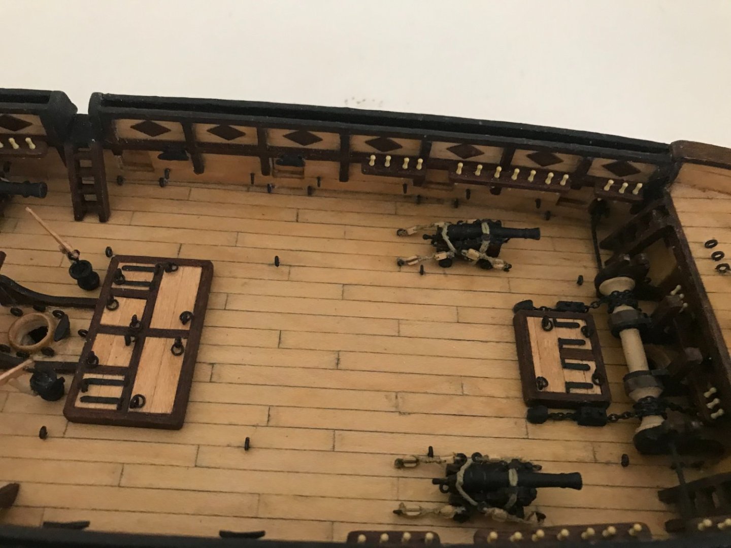
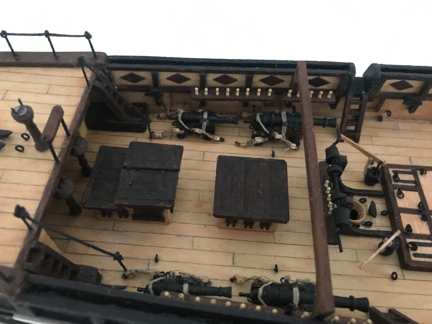
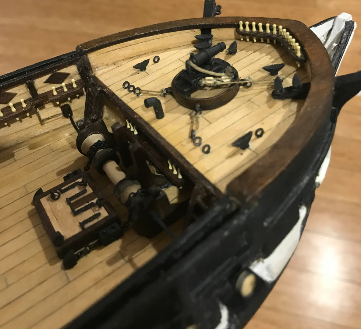
Thanks for the comments Rob and Don. So for the forecastle details the first step was to blacken the chain. I have outlined how I made my home-made blackening solution in my bounty’s launch build log but it basically involves using copper sulfate and bicarb soda to make copper carbonate which can then be added to ammonia to give the blackening solution. I was still using the same batch from my Bounty’s launch, and I think it is much weaker now as some of the ammonia has evaporated. It took over 5 hours to produce the colour seen here where it was achieving the same results in 10 minutes a year ago. I guess the container must not be particularly airtight. Also, on a few other Beagle threads, it's been mentioned how crowded the belaying pins at the foremast are. Anatomy of the Ship indicates that there should be some eyebolts around the base of the foremast to possibly ease this. It's pretty clear why OcCre has not suggested this, as it is going to be a pain in the **** to tie off ropes here once the mast is in, but why are we here if not to suffer? I'll probably tie off the threads to these eyebolts before adding the mast, which might make things a bit easier. Painting the windlass was fun. The beige I used for the pins didn’t look quite right on the windlass as a whole, so I added a tiny bit of brown. Painting in the lines was a challenge that took a few goes to get right. I also made the carronade. The top ring in my kit was very poorly cut and one edge was thinner than the other side and it broke as soon as I cut it out. I had to bend some 1 x 3 strips to give two half rings to make up a new one. I did also add some gun tackle using 2 mm blocks. The hatchway was also fun to make. I added some hinges to the hatches with some off cuts from the eyebolts. I also made up some chain stoppers. I’m not really sure if they’re quite right but I think they get the idea across. And finally, the two binnacles have been added. There’s a bit of a story as to why I have two. From anatomy of the ship, it’s clear that two binnacles were onboard, while the kit only has one. I noticed this months ago and emailed OcCre asking to pay for an additional binnacle as well as shipping. They may have misunderstood me as they assumed I had a missing part. They sent over a bunch, so I have way too many now, but I could at least install the correct amount. But as many other people have mentioned, OcCre definitely has top notch customer service, which I guess is something to keep in mind for any of their kits. Anyway, I'm having a lot of fun with the little details, it's definitely one of the most rewarding parts of the build. The thought of building the boats is a bit daunting as I think I've set myself a few challenges there and I'm not really sure how it's going to turn out. The next few updates shouldn't be too far off though.


-
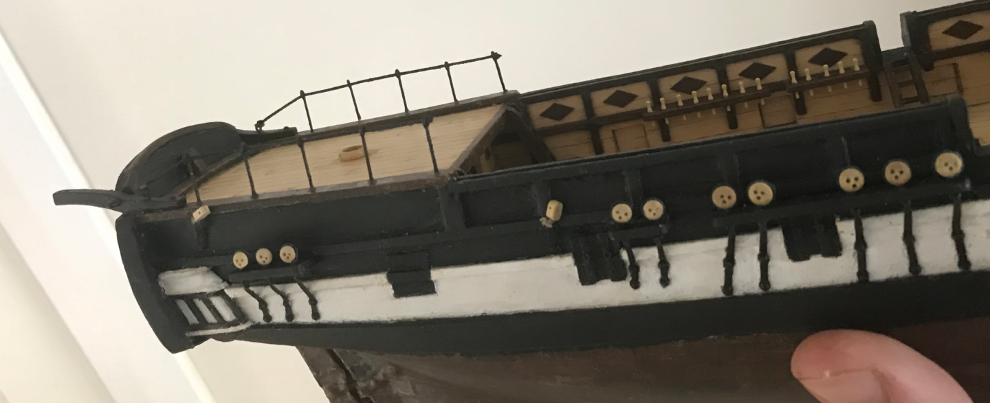
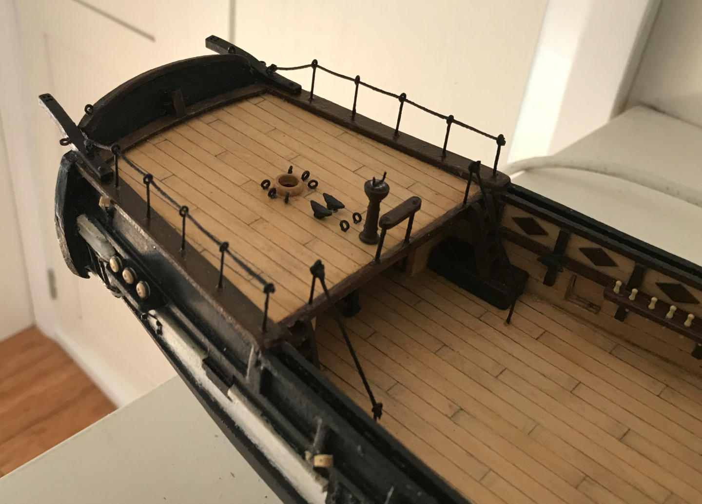
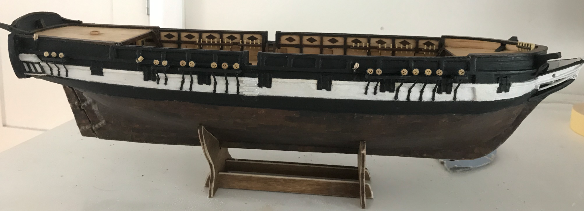
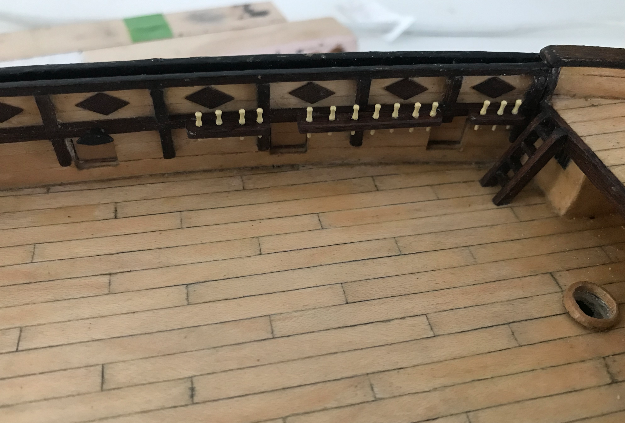
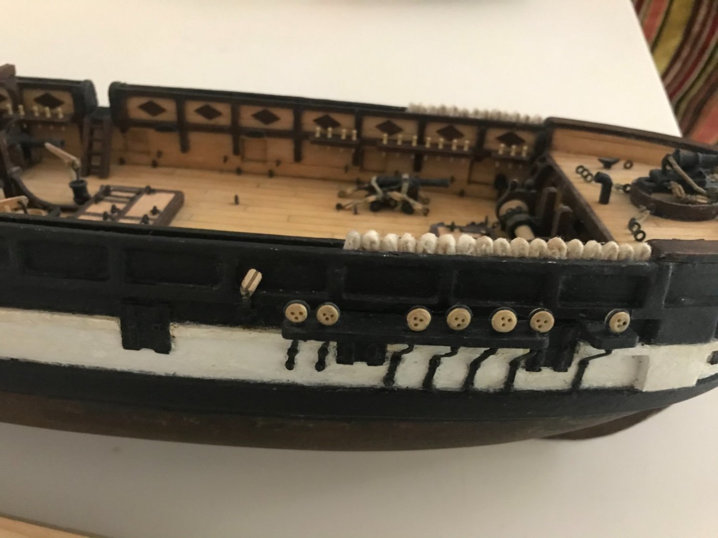
Okay, so went a bit dark there. I finally have a couple of weeks to give the boat some undivided attention. I was really struggling a bit to motivate myself to the deadeyes again, but I got through it. They are now wooden and appropriately sized. I also finished the new belaying pins with the new pin rails. They are 9 mm brass pins painted a beige colour and I think they look right now. It seems like it is pretty difficult to get correctly scaled wooden belaying pins that won't be extremely fragile, so the painted brass ones will have to do. And then onto new and exciting things. So first up is the poop side rails, which are extremely delicate and a bit tricky as the eyebolts provided are a little short and had to be reinforced with a lot of epoxy to make somewhat stable. I also finished the azimuthal compass and the other poop details. I did print out a little compass rose to glue on the compass, but it was too small to print properly. I touched it up with a pen, but it looks okay, I think. I’m not going to add the stowage blocks yet as I’m not really sure how the whaleboats will be placed yet. I think once I’ve made those and get a better sense of the size, I can add them. Anyway, working on the carronade and windlass now, good to be back.