MORE HANDBOOKS ARE ON THEIR WAY! We will let you know when they get here.
×


Steve20
-
Posts
168 -
Joined
-
Last visited
Content Type
Profiles
Forums
Gallery
Events
Everything posted by Steve20
-
HMS Victory Renovation - Outer Planking Removed
Steve20 replied to Steve20's topic in Nautical/Naval History
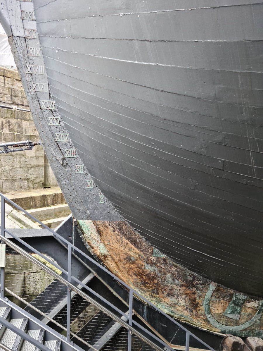
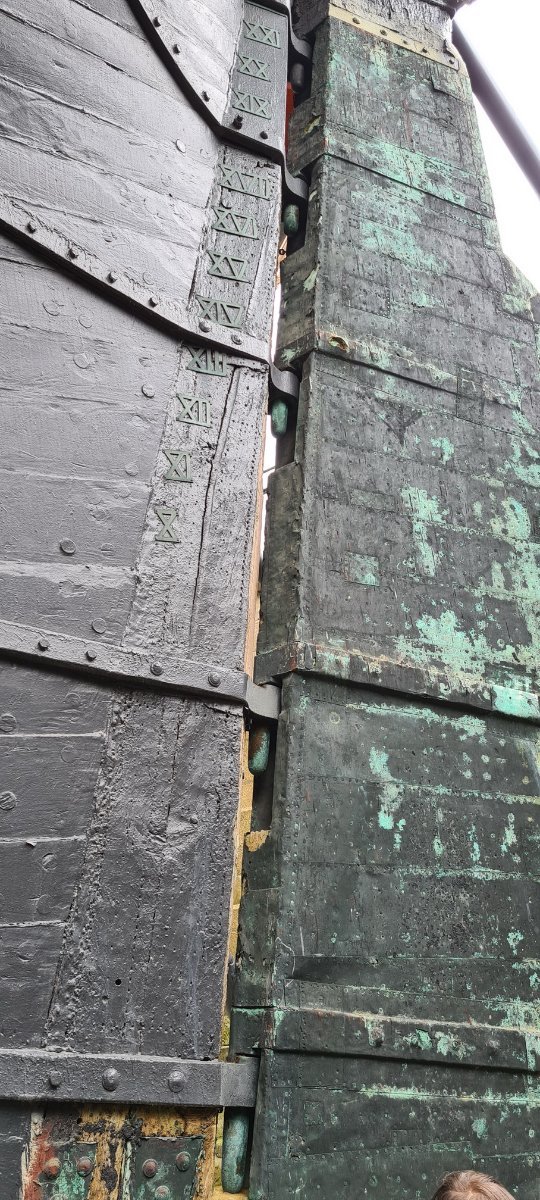
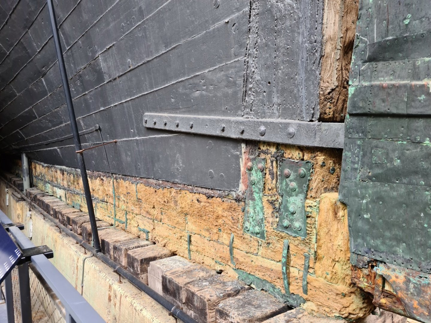
The below pics show elements of the bow, keel and stern, which I believe date from the 1800’s and perhaps even earlier. (I've since found out that they date to the time of launch in 1765 - Steve)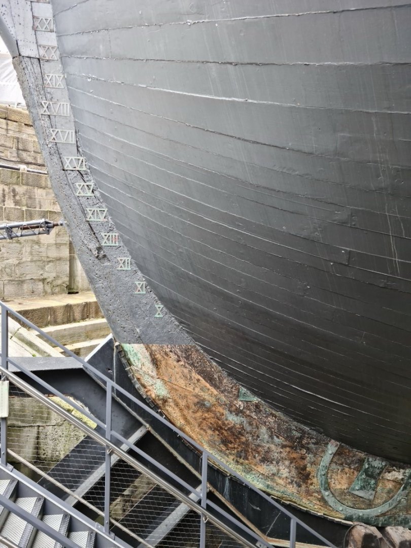

- 53 replies
-
- 14
-

-
HMS Victory Renovation - Outer Planking Removed
Steve20 replied to Steve20's topic in Nautical/Naval History
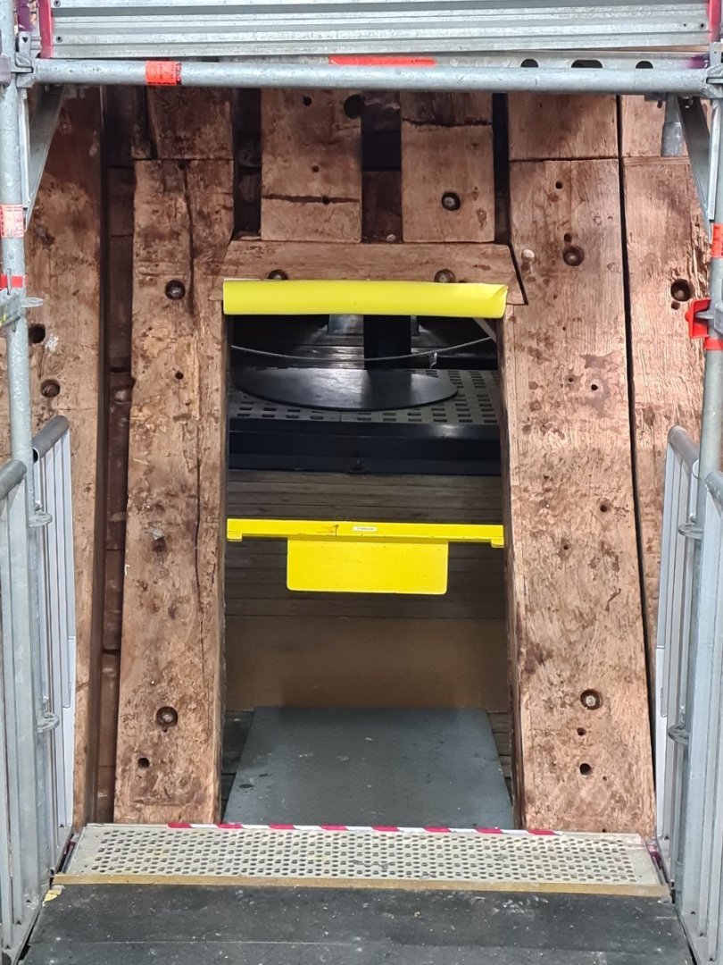
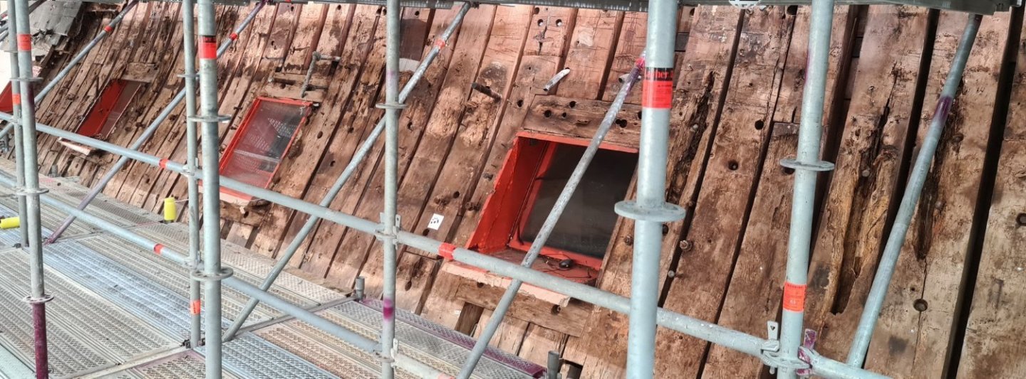
Some more pics: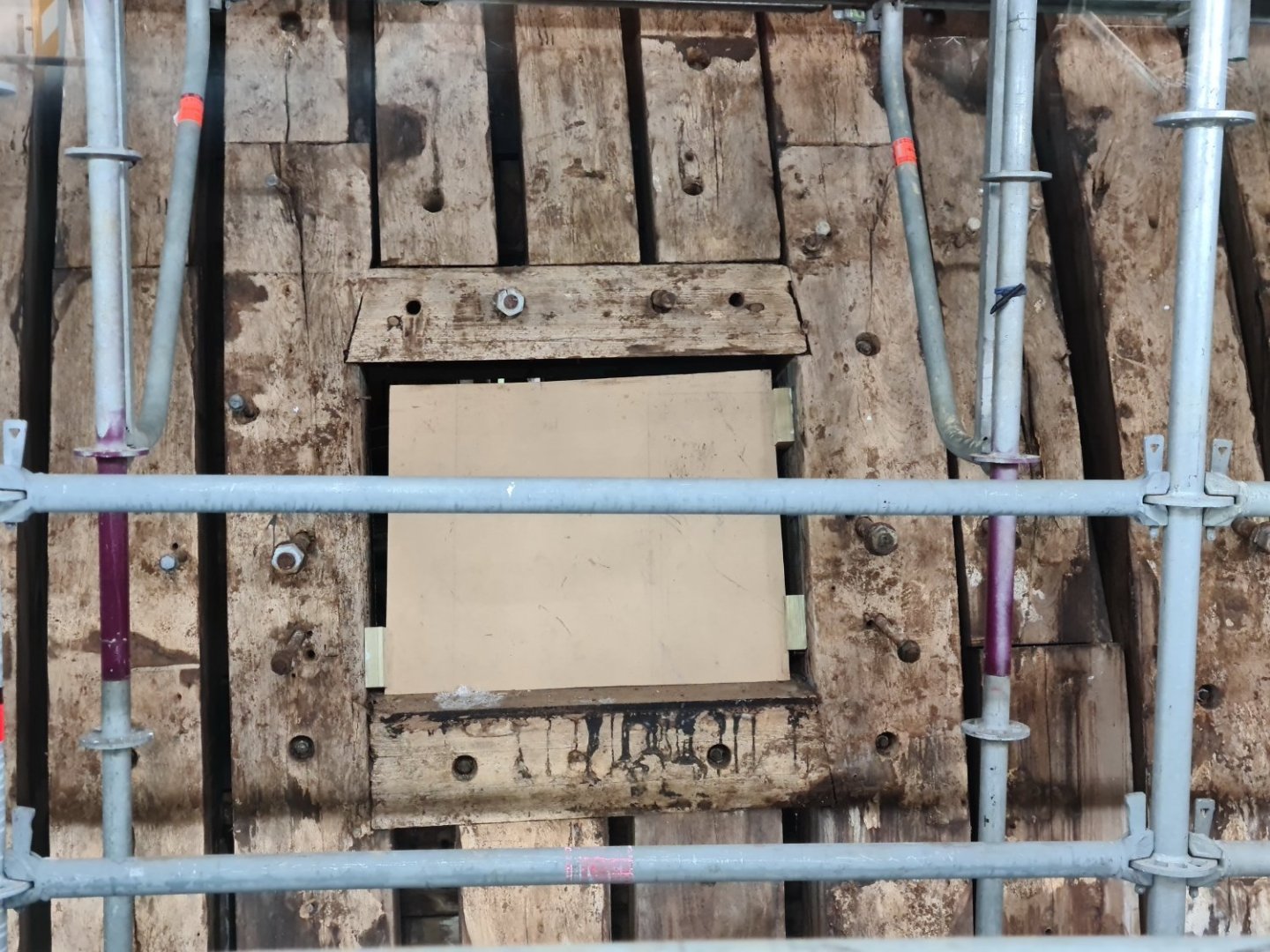

- 53 replies
-
- 10
-
-
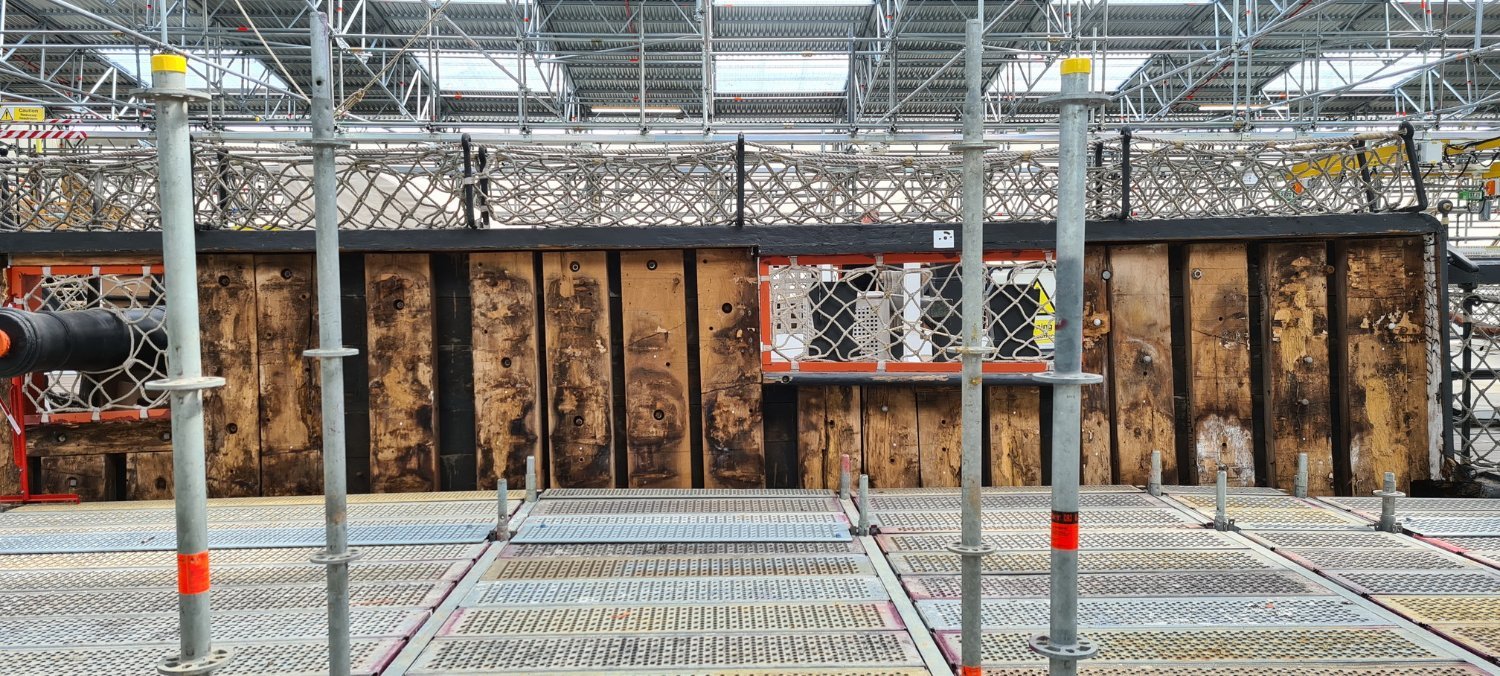
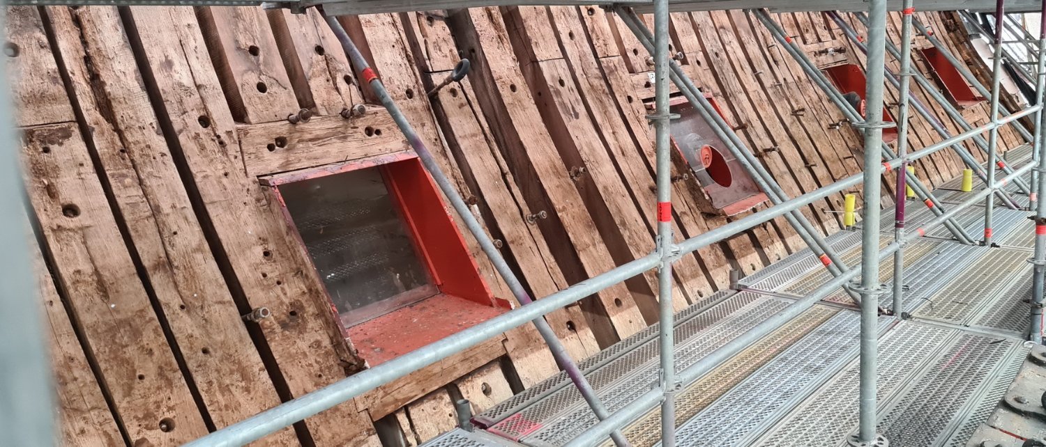
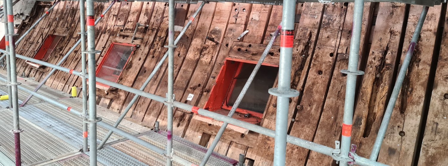
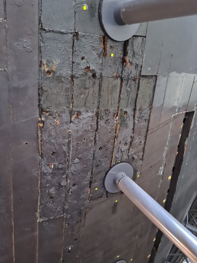
HMS victory is currently undergoing a £35 million (GBP) renovation and outer planking is being removed to access and replace frames that are damaged by moisture, fungus and pests. Below are a few photos I took a couple of days ago of frames on the starboard side. I believe these date from a renovation carried out in the 1900’s.

- 53 replies
-
- 10
-
-
Then installed them one piece at a time:
-
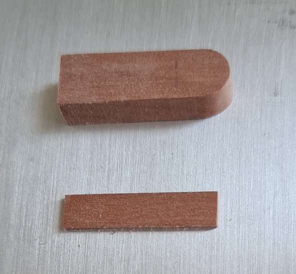
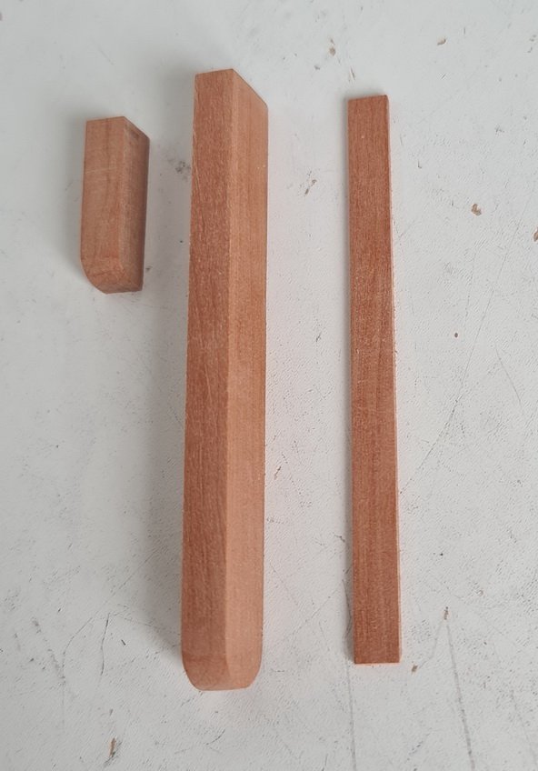
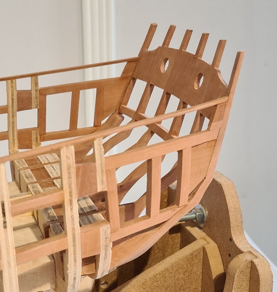
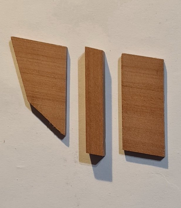
I made the aft hance pieces in three parts and the forward in two:
-
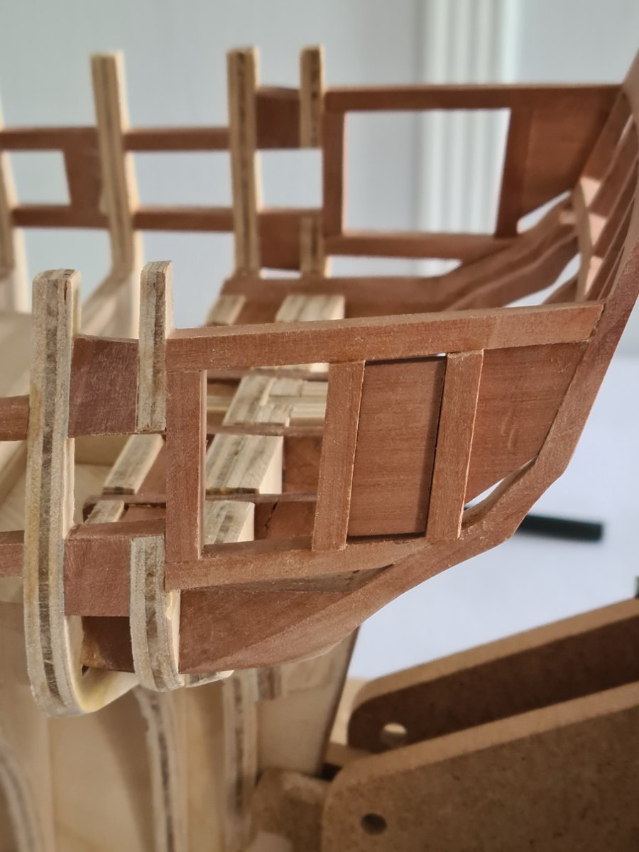
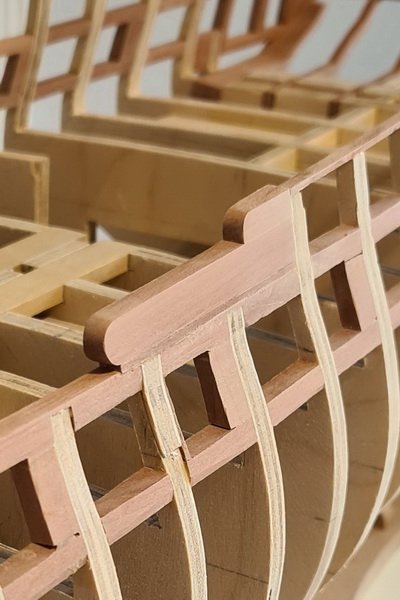
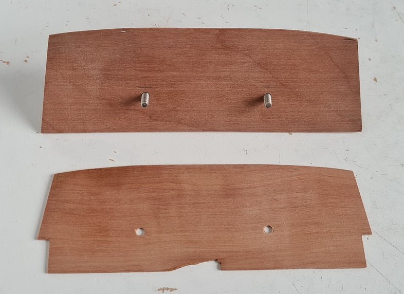
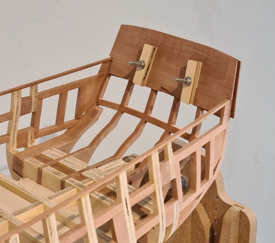
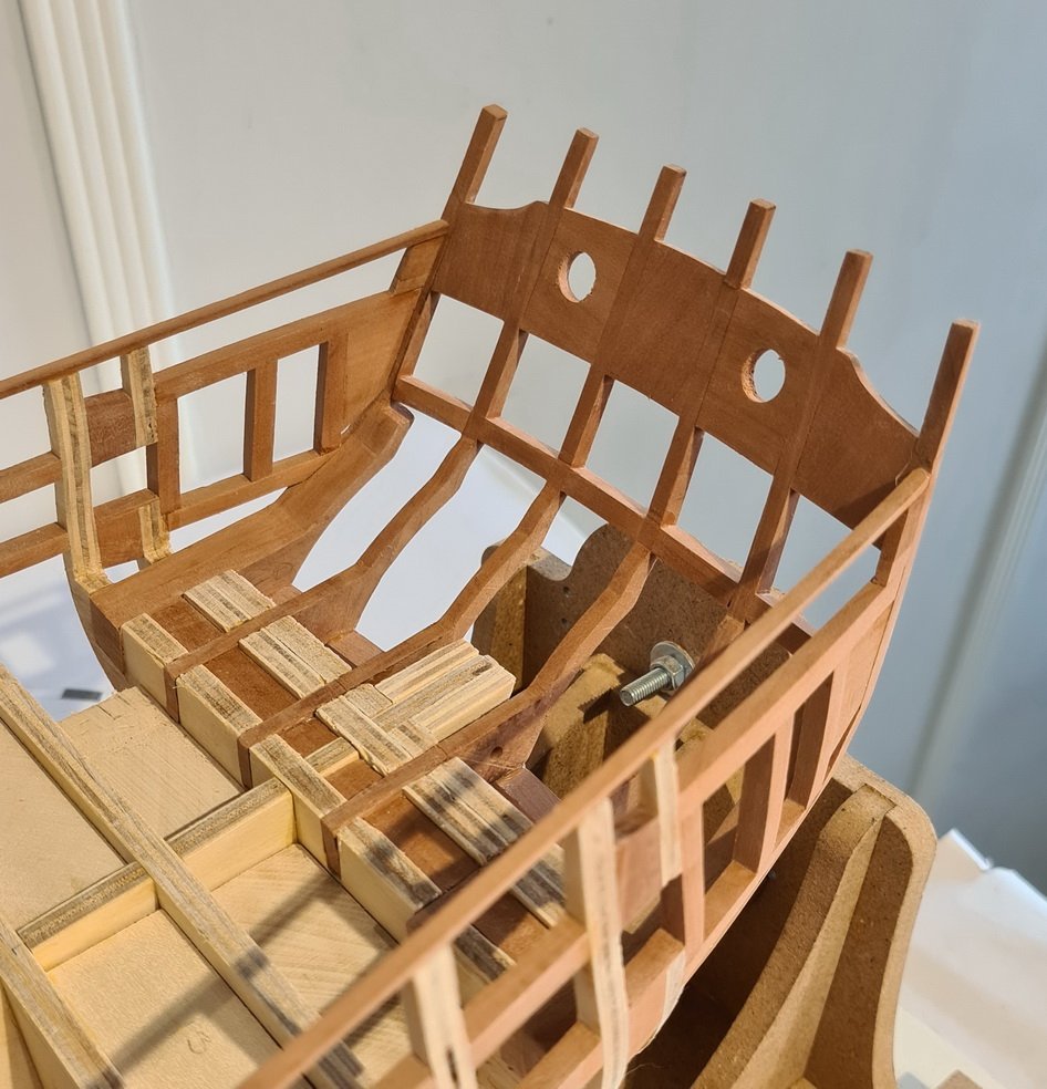
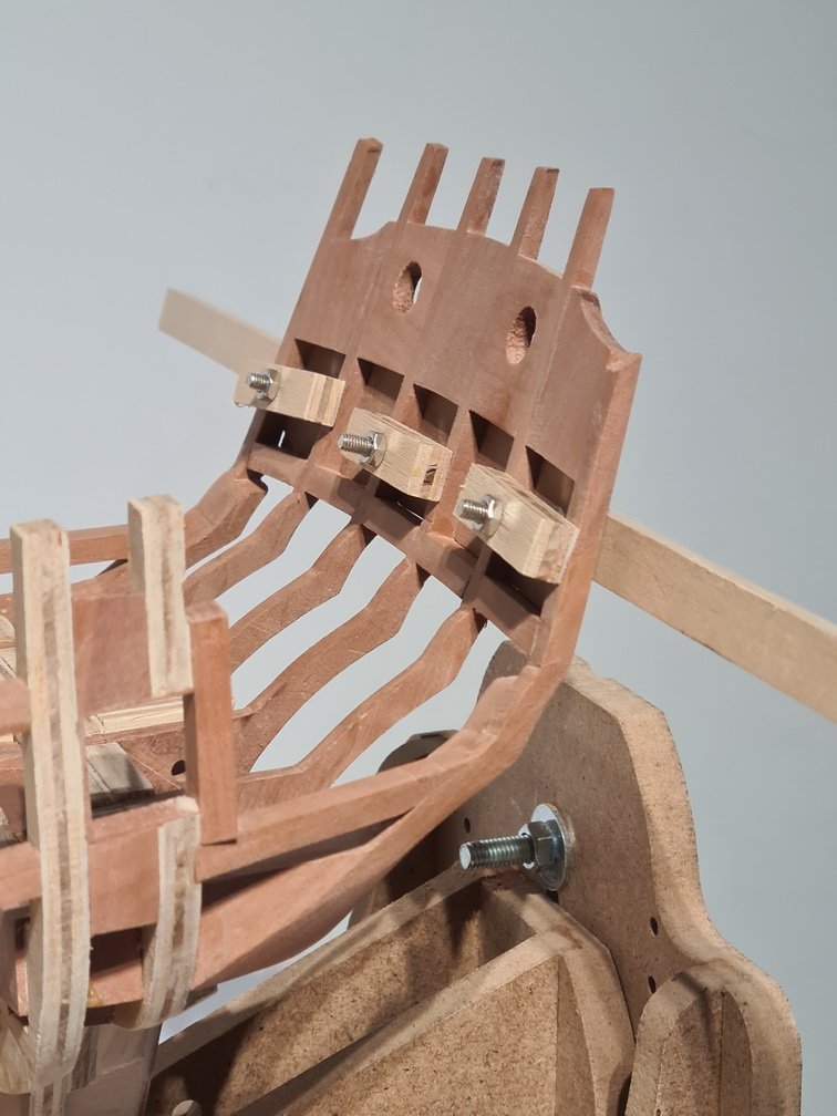
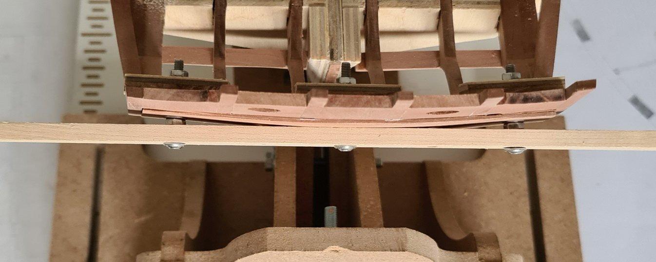
I broke the top of another stern frame whilst working on the stern interior and I definitely don’t want this to happen again. I’m learning the hard way to be more careful, but obviously not fast enough, so I’ve made a protective cover out of material I had lying around.
-
Very nice work. So detailed and precise.
- 642 replies
-
- 2
-
-
- winchelsea
- Syren Ship Model Company
- (and 1 more)
-
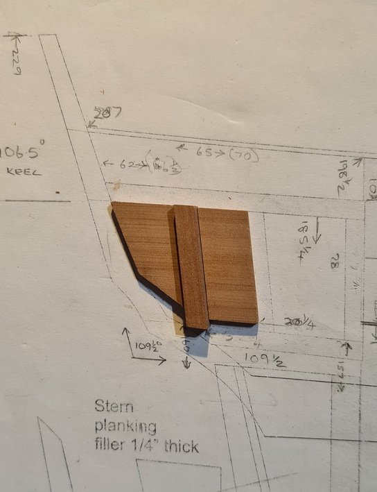
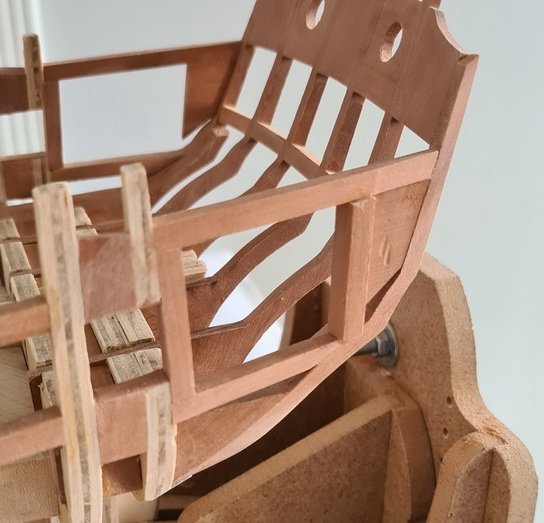
Thanks, Glenn, I had thought of placing a filler piece in the bow but decided I would go ahead without it. However, your advice now convinces me that this is something I should really do, and I made one this morning.
-
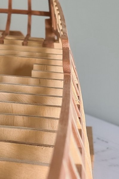
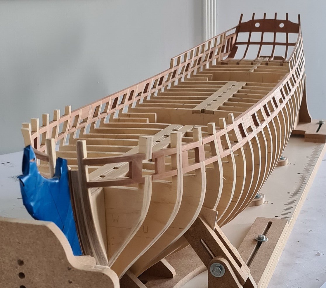
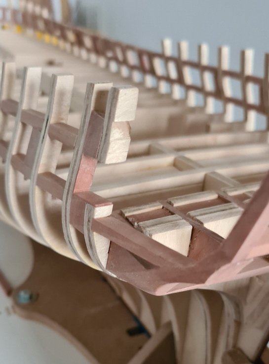
The upper part of some waist frames were a bit ragged and the height needed to be built up in two or three places, but I decided it would be better to sand them all down to a uniform level and place a 3/64” plank on the top. I now need to sand the top plank down just a little (I’ve left a small plus margin for error) but I’ll leave that until I’m ready to plank this location. I’ve been sanding the inside and most excess is now removed but I won’t sand any further until the outer planking is laid. However, I do have some fairing to do outside and there are a few places where I still need to add padding - you can see a couple of these in the photograph.
-
Thanks JJ. I'm also reading up on what's ahead - Chapter 4 in this case.
-
A lot of effort there and the results are really good.
- 840 replies
-
- 3
-
-
- winchelsea
- Syren Ship Model Company
- (and 1 more)
-
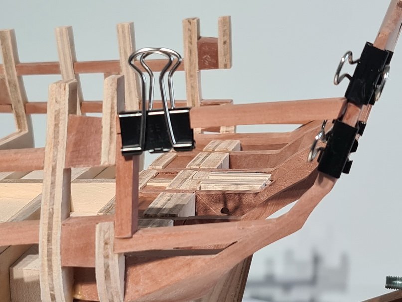
Lastly, I sanded the transom area internally so I’ll have less heavy work to do in this area later.
-
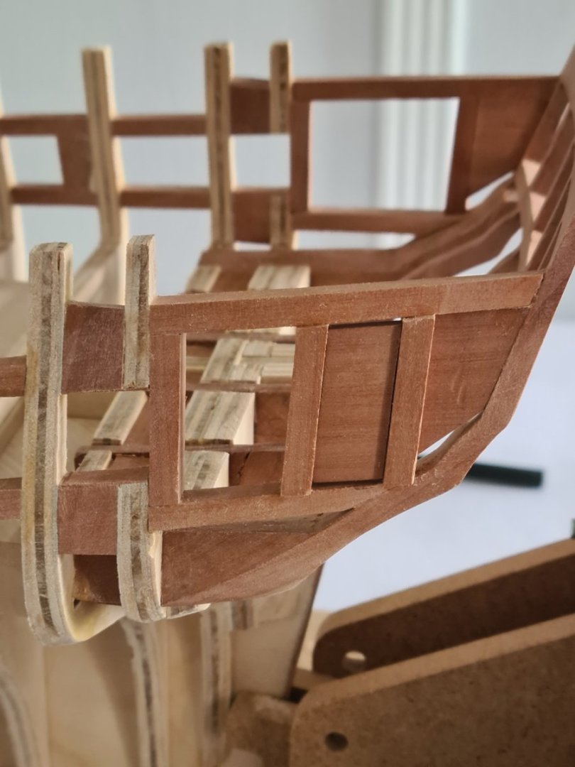
When the glue on the aft upright was set, I placed the second spacer against it to set the distance for the centre upright.
-
To position the uprights, I made two spacers. Working forward from the transom, I glued the first spacer into place as it would also be beneficial later to lay the internal planking upon.
-
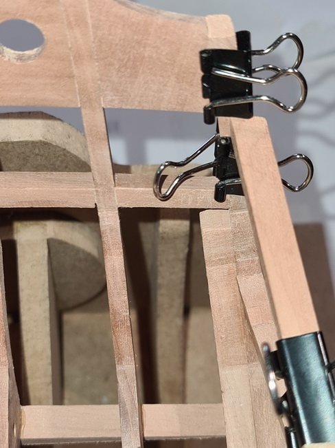
I sat the upper longitudinal on the forward upright, confirmed the forward end A0 elevation, then fixed a paper clip at the aft elevation for this end to sit upon.
-
Next I glued the forward upright onto the lower longitudinal.
-
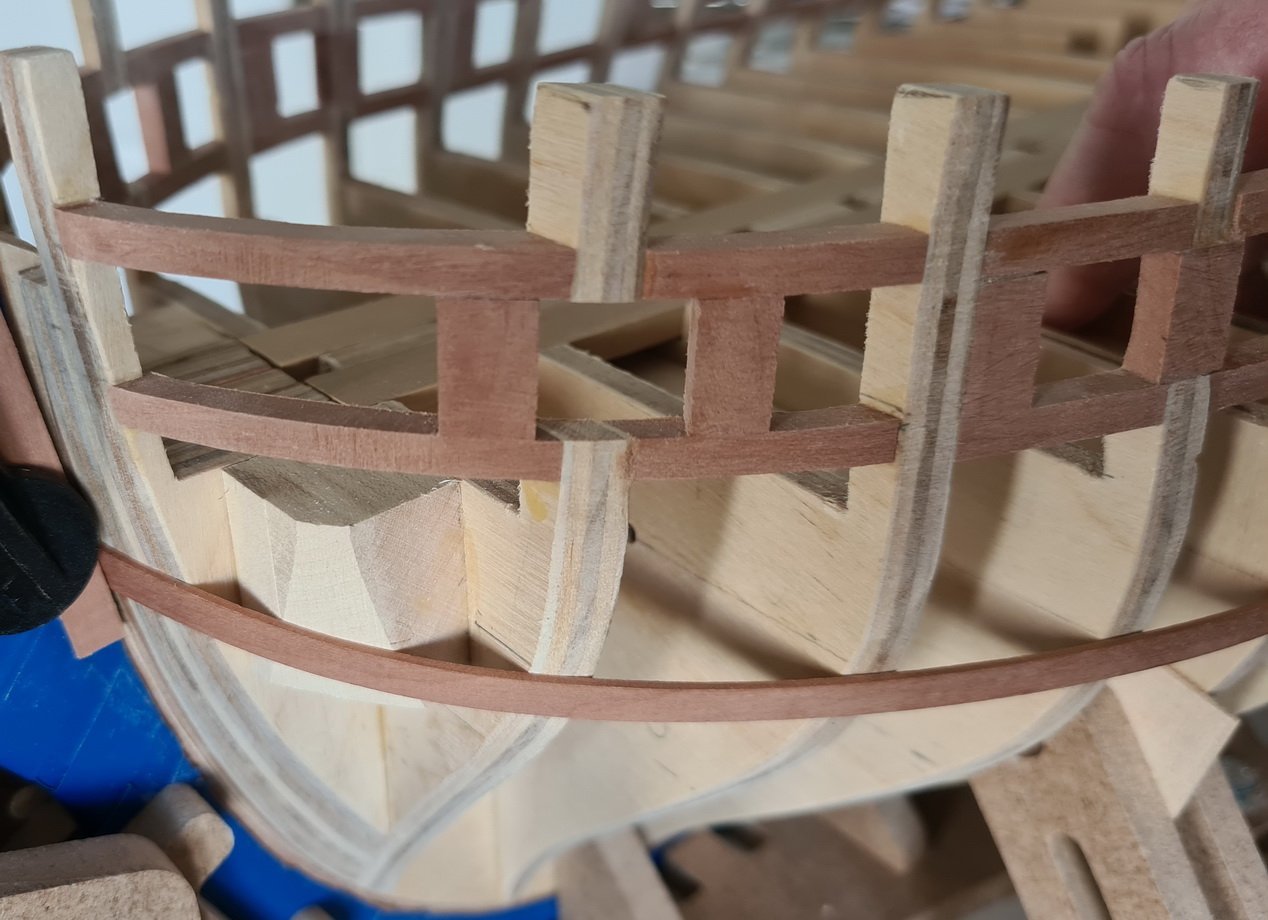
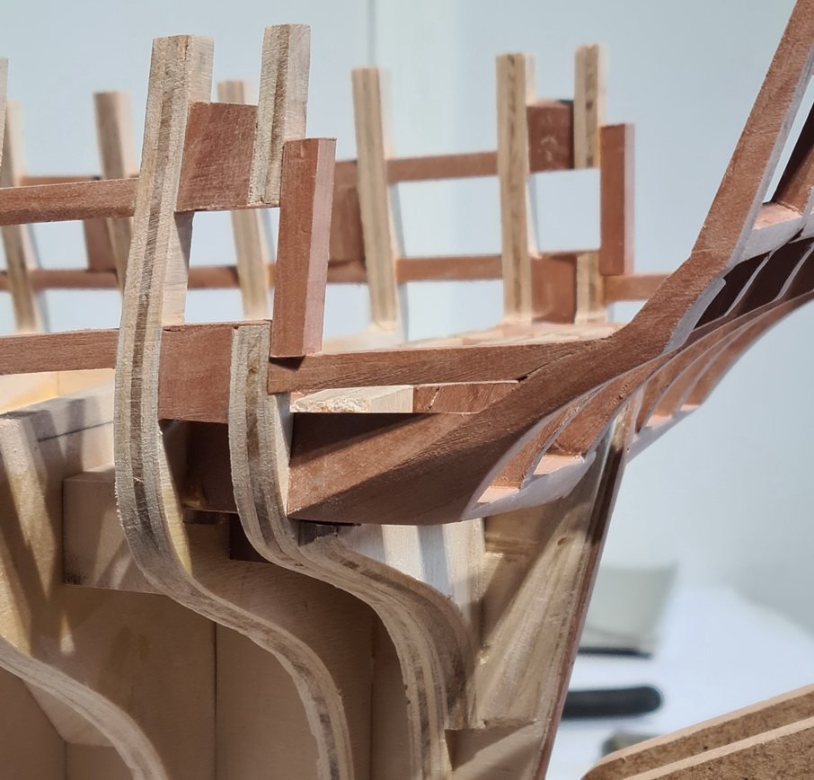
I’ve now moved on to the quarter gallery framing and to make things easier I provided one fixed point for each successive piece to land upon. I started with the forward end of the lower longitudinal by taking the upper side to keel elevation from the A0 drawing and cutting a slot at this height in bulkhead 28 for the longitudinal to set into. I cut the longitudinal a little over length, shaped the after end to fit the stern, and sanded the forward end until the after end dropped to the right elevation.
-
What you've done looks really good. Your work is oustanding.
-
Your planking is so good, Frank, it's very nice to see. I admire how you've got it so right.
-
Good idea for the gunport lid assembly, Ben. Finished lids look very good.
- 399 replies
-
- 1
-
-
- winchelsea
- Syren Ship Model Company
- (and 1 more)
-
I had an error to correct on Bulkheads 27 and 28 as they rake aft because I did not cut the false keel joints properly vertical. These were the first pieces that I’ve cut, so I was trying-out printing to adhesive paper after removing sticky labels, then transferring the image to the plywood using pressure. This method didn’t work well for me as the transferred image was not very clear, so for the bulkheads I switched to pasting paper cut-outs on to ply with a glue stick. Anyway, I really messed up with the image transfer as I must have let the adhesive paper shift. However, as the fulcrum is near the top of the bulkhead former it only throws the bulkheads back just over 1/16” at deck level and I thought I’d get away with it by compensating with the stern framing placement. Reading ahead to Chapter 4, though, I was reminded about gunport placement so now I’ve shaved the bulkhead down to correct the distance between the last two pairs of gunports.
-
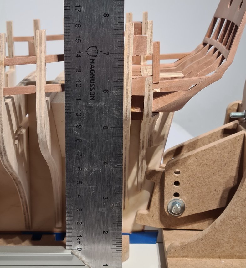
The stern frames are in place and I’m now sanding the transom down to 3/32” at the upper sill top edges as it’s currently about 1/8”. Whilst doing this I’m working on the quarter galleries. I did mange to break the top of the port ‘C’ frame, but I will not repair this until I’ve finished the quarter gallery framing.
-
The detail in your work is remakable and your model very impressive.
-
That’s my big concern, Glenn. The stern frame positioning is not so easy and a mistake here will really mess things up later-on. I find Chucks drawings are excellent, though, both for detail and for accuracy. I verified a lot of measurements to get my badly cut bulkheads and frames correctly positioned, and although these were made from the printed A3 and A4 drawings, when each is properly lined-up, dimensions are always exact to those I check against the A0 drawing.
-
Thanks JJ. I've a bit of making good to do where some of my bulkhead frames were 1mm - 1 1/2mm off centre in the waist area but I hope to get it right for the future.