HOLIDAY DONATION DRIVE - SUPPORT MSW - DO YOUR PART TO KEEP THIS GREAT FORUM GOING! (Only 20 donations so far - C'mon guys!)
×


Matrim
-
Posts
1,401 -
Joined
-
Last visited
Content Type
Profiles
Forums
Gallery
Events
Everything posted by Matrim
-
ZZ: Let's also keep in mind the issue of scale accuracy. The caulking between deck planks is likely to be no more than maybe 1/4" to perhaps 3/8" or so wide. At 1/48 scale, that would be about .005-.006". Even if the caulking were three times that size, you are still only talking about 1/64" or so wide caulking strip. It is possible to use thin black paper to represent such a thin caulking strip, but I have found that black paint along the edges of the plank produces and excellent result. You can also use the old lead pencil to color the edges of the plank. These are all a bit more traditional and time tested methods. Russ
-
Hallo ZZ, I did not see your question earlier, due to the fact I wrote my last post in the same time like you your question. Sorry! It is a fine black or dark-grey card-board between the single planks. This is producing in this scale with "real thickness" of planks (not like the thin "false planks" of kits) the best results! Have a look at this photo and you see a little bit the bigger gap between the planks (between the 2nd and 3rd plank from the right) and at one location (between 4th and 5th plank) the little bit "overlength" of the card. Please have in mind that this photo was made before final sanding and finishing of the deck, therefore the "unclean" surface of the planks etc.

-
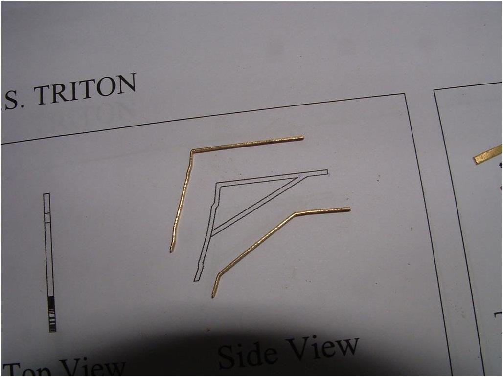
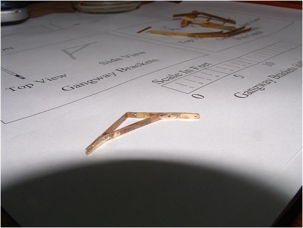
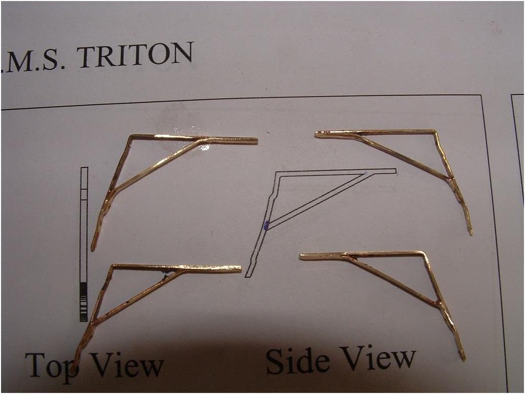
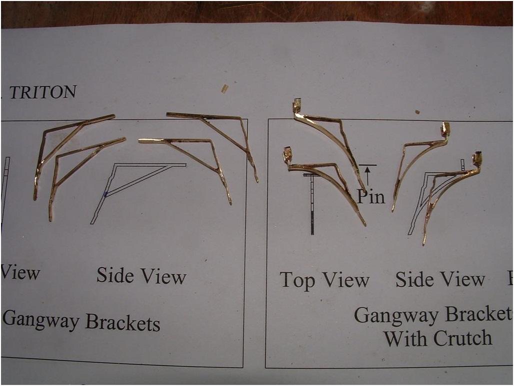
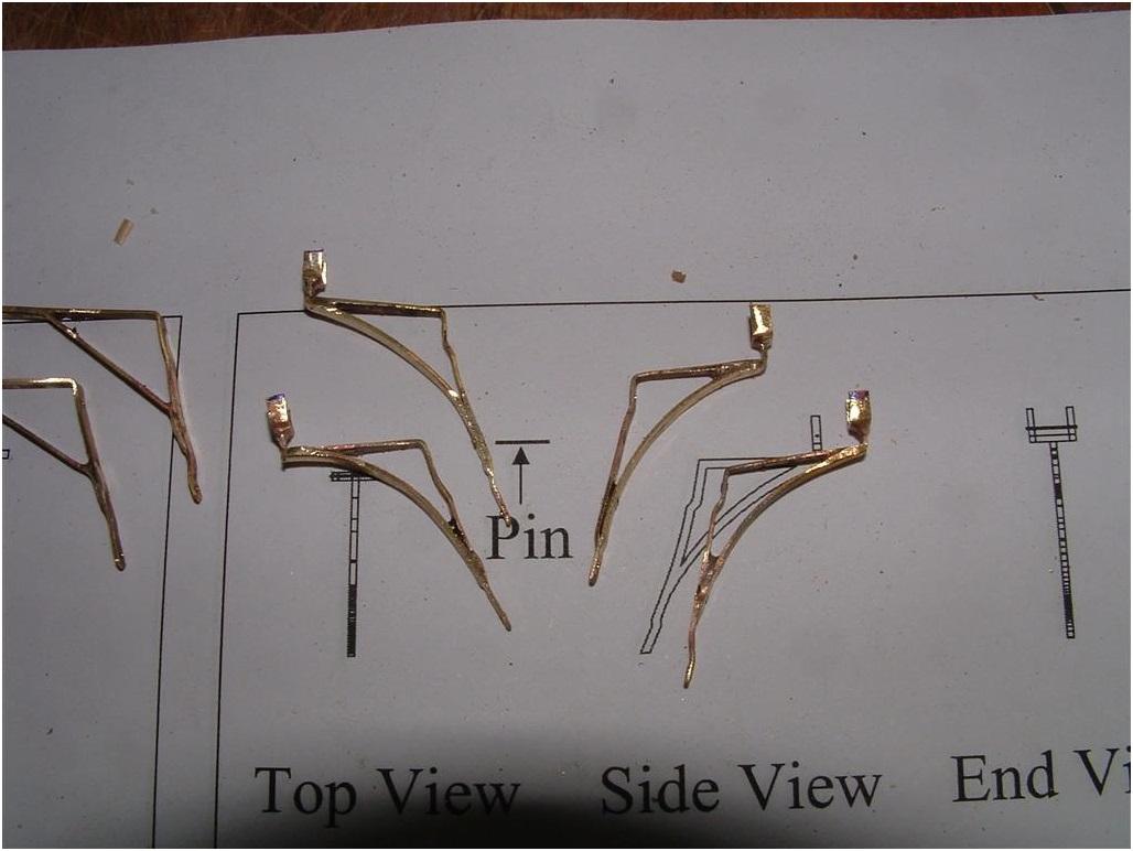
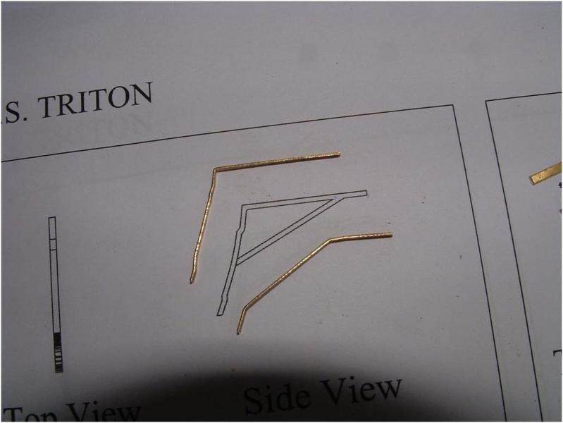
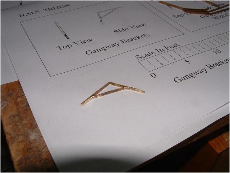
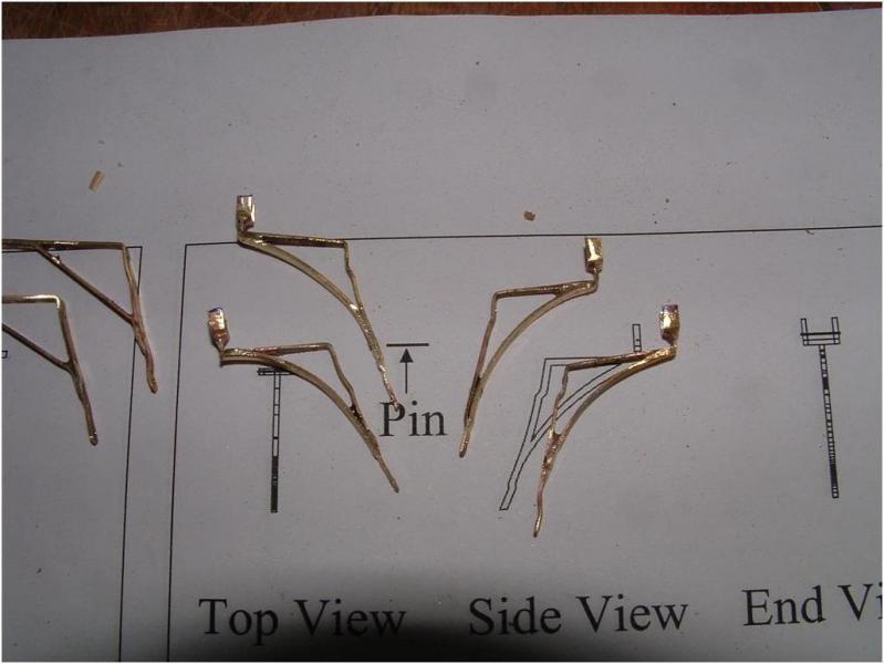
Russ explained very good the important steps for the making of the Gangway Support-or Iron brackets Prepared elements Finished element with already prepared holes for the installation Brackets without and with Crutch The last final shape the Brackets will get during installation at the Spirketting and Clamp with a little bit pressure,in order to get the same shape like the planking After blackaning the brackets can be installed and the works for the Gangway can be started


-
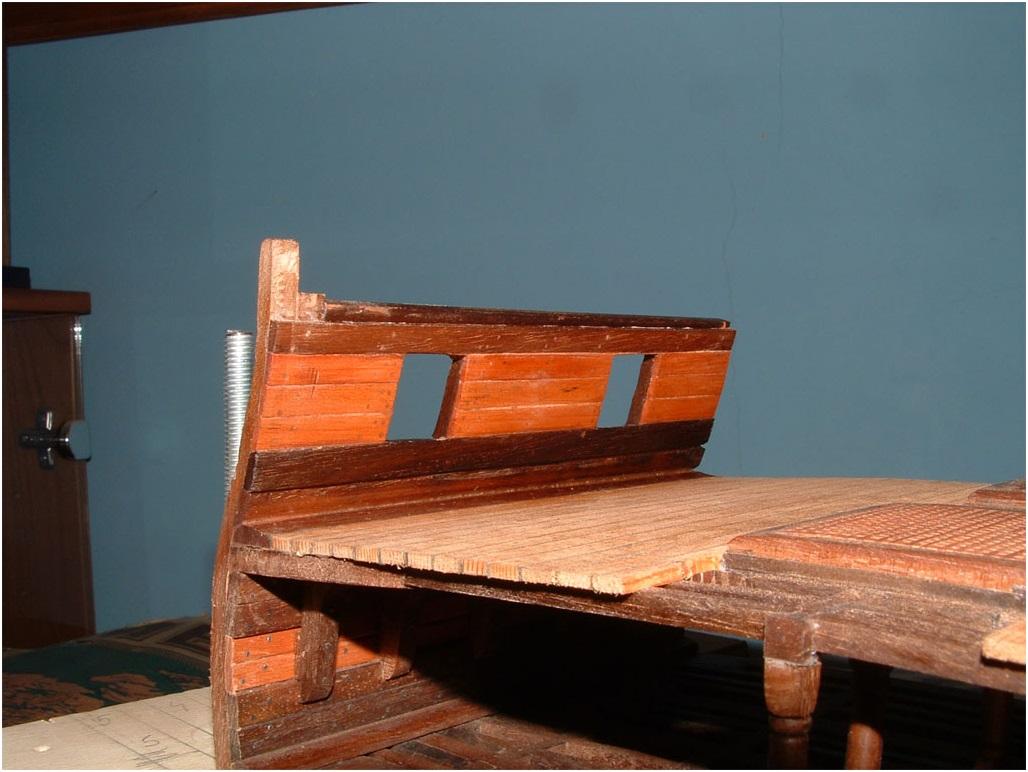
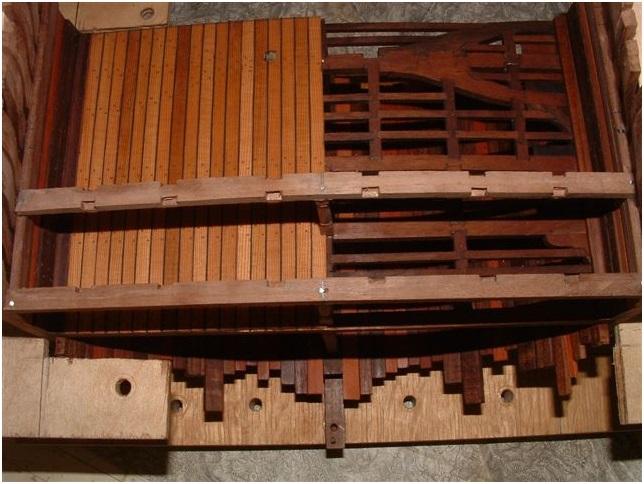
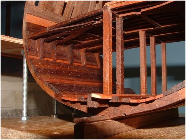
Today some photos of the Inner Planking, Gundeck-spirketting and Gangwayclamp.

-
Hallo Christian, when you remember we had the same subject on this building log some weeks ago when I showed the lower deck,when Russ and myself where discussing the available documents. As Russ explained, there could be one or also two treenails used, nothing is fixed. Also Goodwin is showing in his book partly in sketches two, the HMS Victory has two, and also Peter Goodwin is showing on the deckplan of his "Anatomy of Ships"-book of the ALERT (book review will come in short time) diffinitely two. A lot of other publications are showing one....... What is correct? We do not know !.... like I wrote before....Both would be possible: I guess that was at the end a decision by the client and /or the shipwright influenced by the available time for construction and off course by the available money. But this is my personal opinion...maybe we will find it out once The fastenings on the beam arms I would not do any more, here I give Russ completely right with his statement 8).......but if you see already on the lower deck it is the same made and it would look a little bit stupid when on the different decks different fastening-pattern would be used.
-
Christian: We have been going round and roung on this subject in other threads, but I think that there is no way to be absolutely correct on how many fastenings or how many of them would be visible. I would use one in each beam and then two where the planks butt. That's what the best British research on the subject says and that is what I would follow. Uwe chooses to view this subject differently and that's his perogative. I have never seen a British ship modeled with two treenails in each plank, but you guys are free to do it however you want. That's the beauty of scratch building. I would say that there should probably not be any fastenings in the beam arms. I have never seen that done on any model of a British ship. The beam arms were not there so much to support the deck planking as they were to stiffen the hull around the main mast. It is more likely that, if the planks were fastened to the beam arms, it was done from underneath rather than from above. Goodwin does not address that except to say that fastenings from underneath were used on the ledges. As far as research sources go, Mondfeld's work is not good to use for a British ship as it concentrates on European ships mostly. Goodwin's research is much more recent and much more on point as it dealsspecifically with British warships of this general time period. Russ
-
Hallo ZZ, the deck-planks are made out of Lebanese Cedar which has a fine but clear grain.In my opinion it looks after oiling in bigger scale really authentic. For me the Triton Section built is the first scratch build after several kit-models, but I have a very good mentor, Zeljko, who is helping me with advise, technical help, correct materials and also fine metal works like the gun-barrels which you will see in some more posts on the deck of the Triton. It is like in school, the teacher and me, but much better! I am learning a lot from and with him. 8) Zeljko was several time modelling champion in Croatia, with several silver and gold medals according the NAVIGA-rules also at European and World-championships......... So you see the best basis to learn with such a mentor (Many Thanks for this)
-
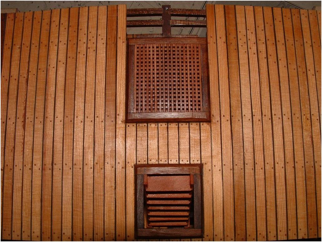
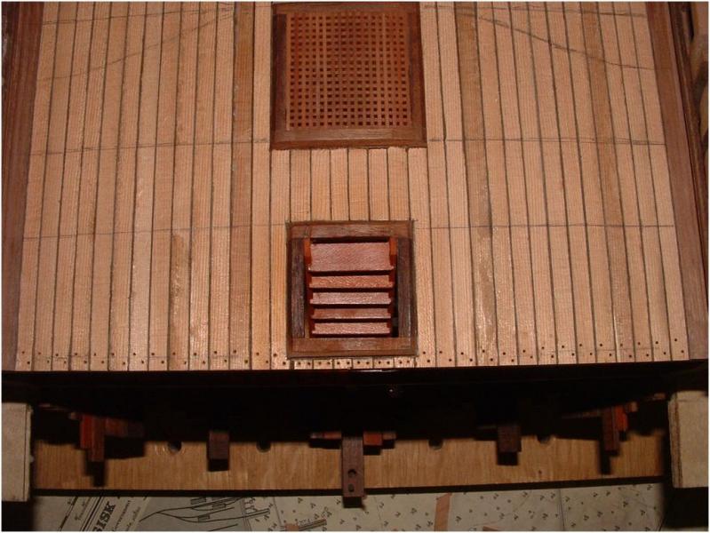
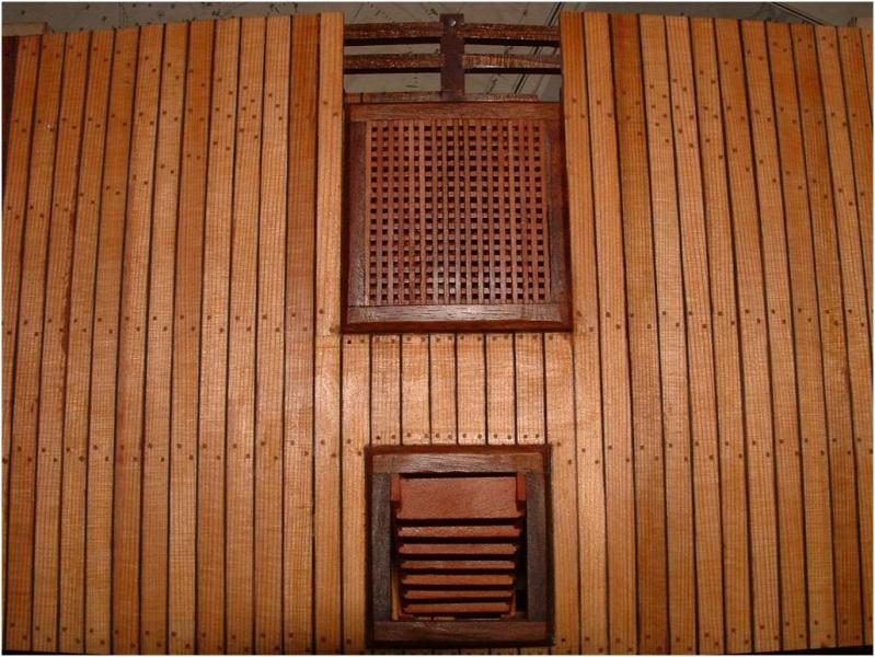
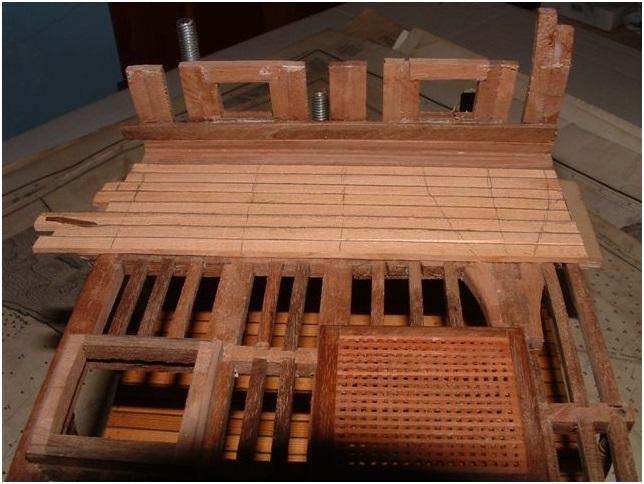
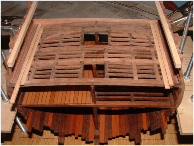
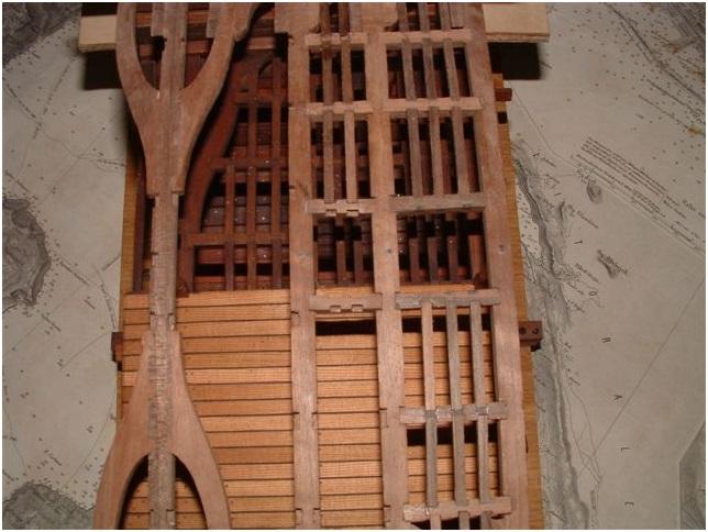
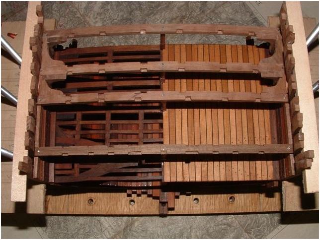
Hallo Russ, there are are a lot of ways to come to the same aim....thanks for your explanations in addition. 8) The grating and the gundeck-ladder is installed and the deck planking more or less completed...here in a side-view The ladder from the top-view inclusive the first nailing of the deck-planks The deck after finished nailing and also oiled finish Comments and questions are welcome..................
-
Uwe: That jig looks pretty good. I like its simplicity. I use my table saw to make ladders. I saw this method in Clay Feldman's book on scratch building the Armed Virginia Sloop several years back. Its a little more complicated, but it produced very good results. You first make the rails for the ladder, making sure they are exactly alike in length and the angles at the top and bottom. Then you create a small base out of plywood, making sure it has squared edges all around. Place some double faced tape on it. Next, position the ladder rails so they are facing one another like a mirrored image with their upper ends flush against each other. They must be placed so their bottom edges are square to the edge of the plywood base. Next, set up the rip fence on your table saw so that the blade will cut the slot for the lowest tread on the ladder. Lower the blade so that it cuts only a 1/32" deep slot. I use a slitting blade that cuts a 1/32" wide slot. When the table saw is set up properly, place the plywood base face down on the table saw with the ladder rails in place on the double faced tape. Then run the base along the rip fence and the saw blade will cut the slots for the lowest tread in both rails at once. To cut the next slot, move the rip fence out the distance to the next slot and repeat the cut. Each time you move the rip fence the distance to the next slot until all the slots are cut. If the measuring and set up is right, you will get perfectly matched slots in each rail every time. It takes some time to set up on the table saw and it is good to run a few tests to make sure of the slot depth and so forth, but it produces a good solid ladder. Russ
-
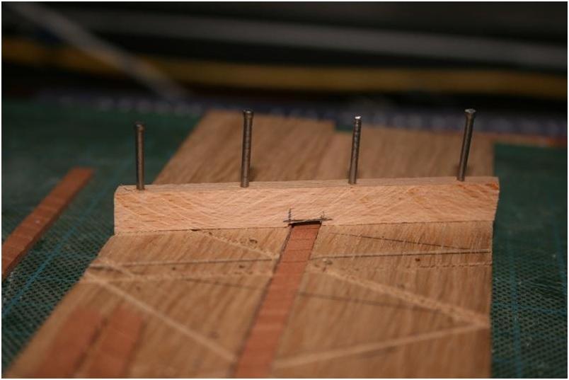
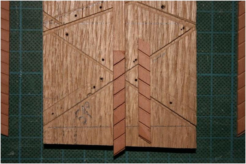
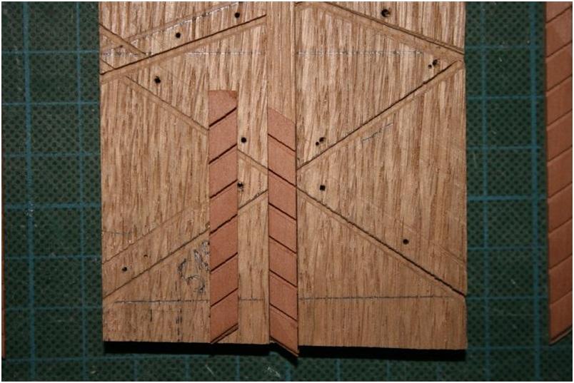
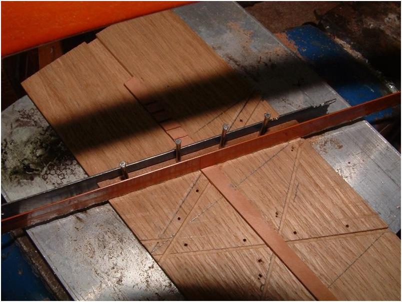
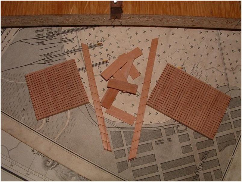
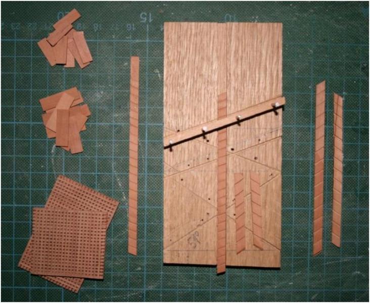
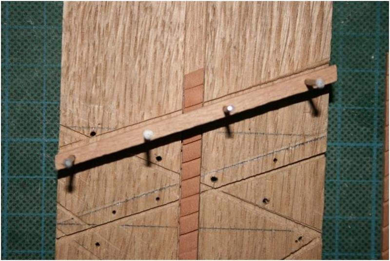
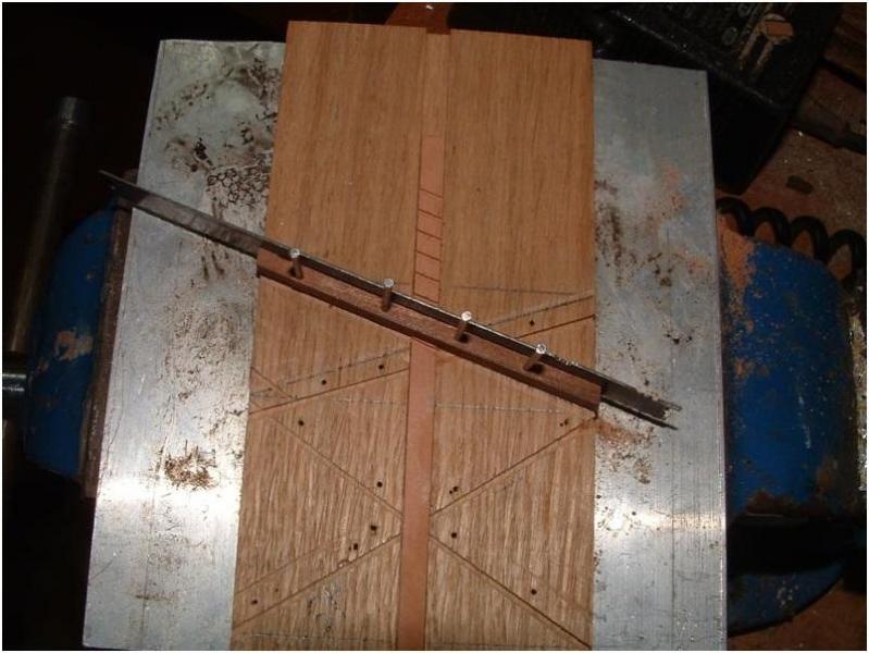
Some posts before I already showed some prepared elements for the ladders and based on request by some members. I want to show today the used small jig. The idea for this jig I learned from Zeljko and it is helping to get every time the same angles and the same distances of the notches for the steps in the side parts of the ladders! I think that the photos are explaining a jig or a tool much better than words (especially when they are coming from myself), therefore I made some more photos to show the principle of this jig and explain with words the most important things. This is the mentioned jig with some prepared side elements for the different ladders necessary for the Section. On the left in addition some prepared steps and also once more the gratings. The visible "diagonal" small notches in the upper part of the jig are prepared for the two 70° Gangway ladders and the "diagonals" in the bottom part for preparation of the side elements of the 51° Forward Hatch ladder. In the middle from the bottom to the top you see a bigger (and deeper) notch ("main notch" for later explanations) for the side elements, which has exactly the same width like the side element by itself. This temporary with four nails installed small timber on the top is important to get he same distance between the steps and it is additional helping as a guide for the handsaw. As an example some side elements of the Forward Hatch ladder in the jig, once the left side- and once the right side-element. The jig "in action"................put the side element in the main notch.................with the hand-saw carefully cutting the notch in the side element.................shifting the side element until you see the first cut notch at the other side of the guidance-timber............cutting the next notch....... If the main notch is not prepared too deep,or the side elements of the ladder have a bigger strengththan the depth of the main notch,than it is possible (and very helpful) to use a steel-plate or similar to fix the side elements in addition. Usually it is enough to fix the side element during the sawing with some pressure with fingers against the jig. If there are some questions, remarks, comments or also ideas of improvement ..............please post them if you have other jigs or ways of making the ladders-side elements.........please post them also


-
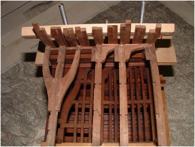
Some more photos of the ladder-way framing The framing and installed next to the grating described in my last post of the building log The members which are interested in the shown saw have to be some more days patience. It is under preparation!
-
Hallo Christian, wait a little bit with the investment for a new saw until you checked out the technical data of this saw! I contacted via Zeljko the producer of the saw and he promised me to send me in short time photos, data and also price of the actual version. The older version I could show here (see also photo of this building log) but it makes not so much sense, due to the fact that the saw was in the meantime adjusted. When I have all data I will present this saw in our area for "Tool reviews" and / or in "Traders and Dealers", I hope that I can make this in short time!
-
Hallo Jim, sorry for the late reply... I was reading your question some days ago and due to the "stress" in last days I forgot to answer immediately to your last post. This table saw is a real fine power tool and a very good alternative to all Proxxons or similiar on the market.......(also an european alternative (220V) for the american Byrnes) Better to say.....this saw is much much better than a Proxxon (I can only compare to this producer because I was never working with a Byrnes). It is a saw devoloped by a fine-mechanic specialist here in Croatia based on the remarks and requests by some croatian ship-modelers (also Zeljko) and he is producing small numbers of this saw (maybe 5 to 10 per year) in the meantime as the "final" version. It has an exact aluminium-table with adjustable hight of the saw-blade, micrometer-stop, with a long extension and fence, etc. The motor is turning the saw-blade via a belt and the saw-blade is capsuled (no saw-dust in connection with motor) including a connection for the vacuum-cleaner! Very very interesting saw and highly recommended ! I will try to get some photos and some more detailed technical description of his "actual" version and will (if there is some interest) show this saw in an extra topic.
-
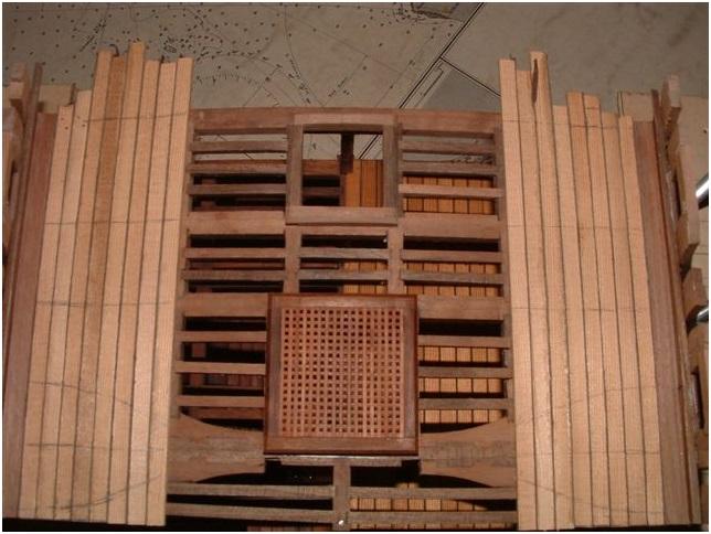
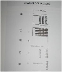
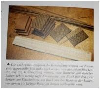
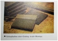
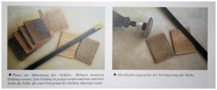
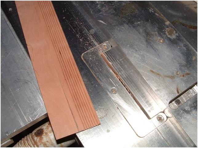
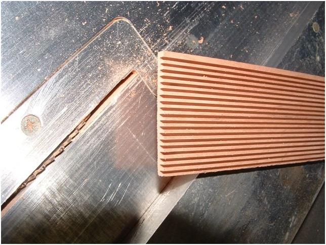
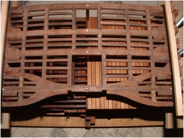
as I already promised I am able to show today a little bit more interesting subject than the already boring carlings and ledges. The construction of the gratings! The way of construction we are following is based on the descriptions made in Bernard Frölichs book "The Art of Modelling" published from ancre: In the first photos I want to show in some copies of the above mentioned book the principle,which is totally different to the way f.e. every time used in kits! Due to the fact that my copy of Frölichs book is the german version I will translate the descriptions of the pics. Here is shown the general princip (thumbnail) 1)The first series of cuts, not deep, in right angle to the grain of the wood (transl.: Faserrichtung = direction of grain) 2) The second series of cuts, deep, in the same directionof the grain 1 and 2) it is not important which of the cuts (deep or not deep) you make first if you have a sharp saw-blade! 3) You see small latches, they have to be installed and glued in the notches of the first cut series (not deep) 4) Cut away of the base (transl.: Hier sägen = Cut here) 5) Reduction of the depth on one side (transl.:Abschleifen = Sanding) I guess with the following photos the principle will be clearer (all thumbnails) Now back to the real life of the Section of our Triton...... The first photo is showing the original timber on the circular saw (A special high quality saw "Made in Croatia") The first of the cuts made Step one is finished, all cuts in one direction The prepared gratings before cutting of the base and sanding. The other visible parts are the prepared ladder-elements The finished grating with frame


-
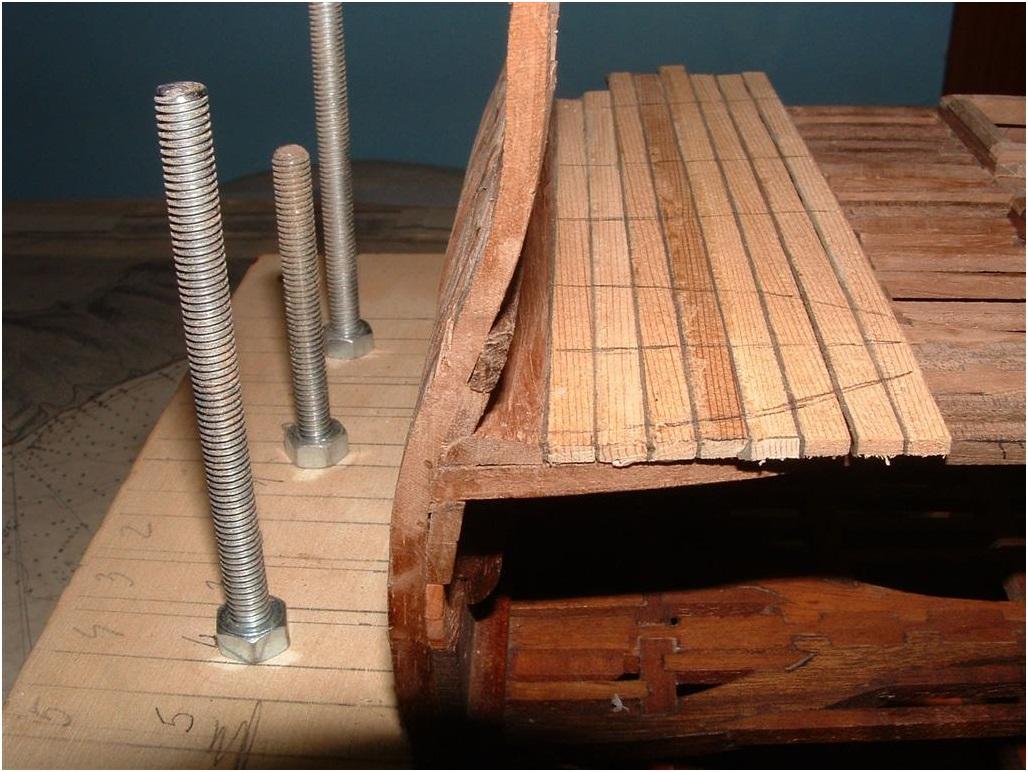
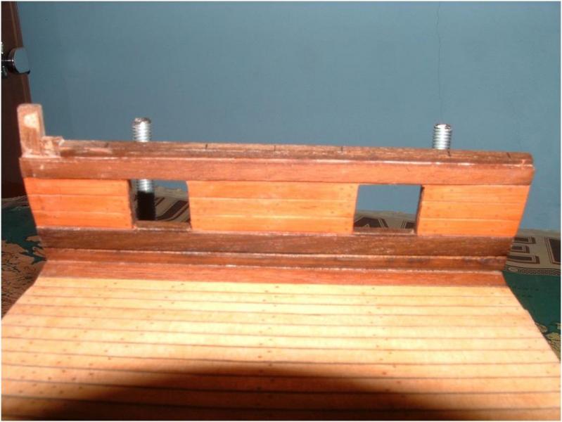
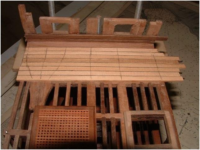
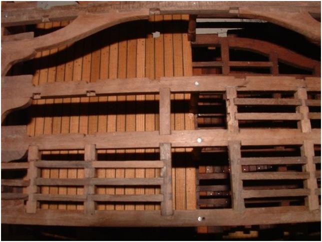
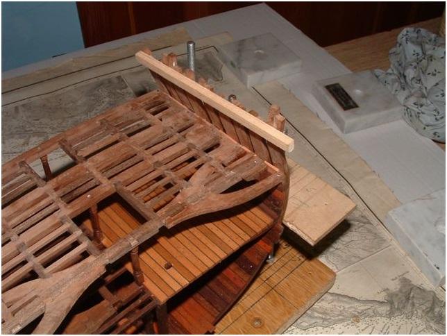
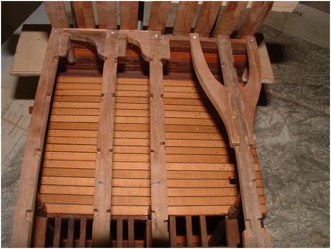
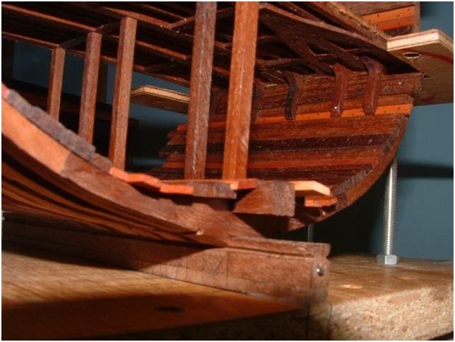
Back to the building log: After so much carlings and ledges for the strcuture the more interesting features, for the modeler as well as for the reader of this topics, are starting: The installed waterways of the gundeck inclusive the Spirketting-planks and the first installed planks of the deck. Have a look at the temporary installed (with two clamps) "beam" next to axis 5 which should help to get each plank ending on the same distance to the last ledge or beam. A detail of the Gun Deck waterway with some more installed planks. (The subject "waterway" we had some days ago in an other topic)
-
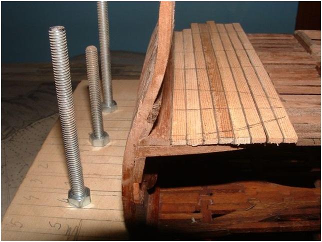
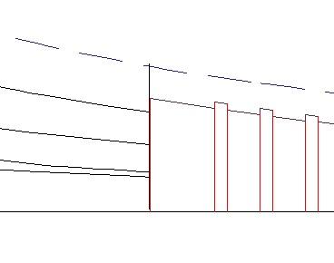
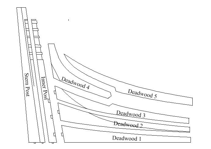
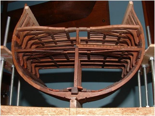
A brief update.I am still beavering away at the deadwood. Here is a cross section of the keel unit with the diagonal lines representing the rising wood between the frames (as I interpret it so far, might be incorrect) And the stern deadwood I might have over sized the height of the stern post as I cant see yet the joint line on the plans One area I am suspicious of is the height of the rising wood when encountering the stern deadwood as follows In the above shot the bottom of the keelson can be seen by the dashed blue line. Looking at the other plans sets (Naiad/Swan/Euryalus) the top of the rising wood looks high to me. If anyone could explain what this height should relate to then I would be grateful - it might cause me to redo the slots on all my square frames but better to fix now than regret later. On the original plans I assumed the keelson sat on the top of the frames and rising wood would be the difference between the seating slot of the frame (which was 13 inches if I remember correctly) and the keel so if the gap for a particular frame between top of keel and bottom of keelson was 20 inches then the rising wood would be 7 inches. Not too difficult to adjust if incorrect though so any comments either way would be welcome. Cheers, Joss.

-
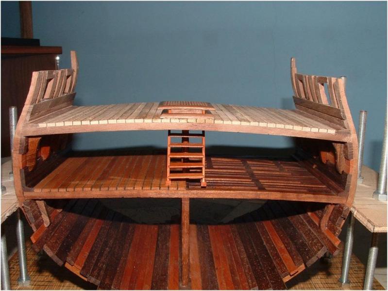
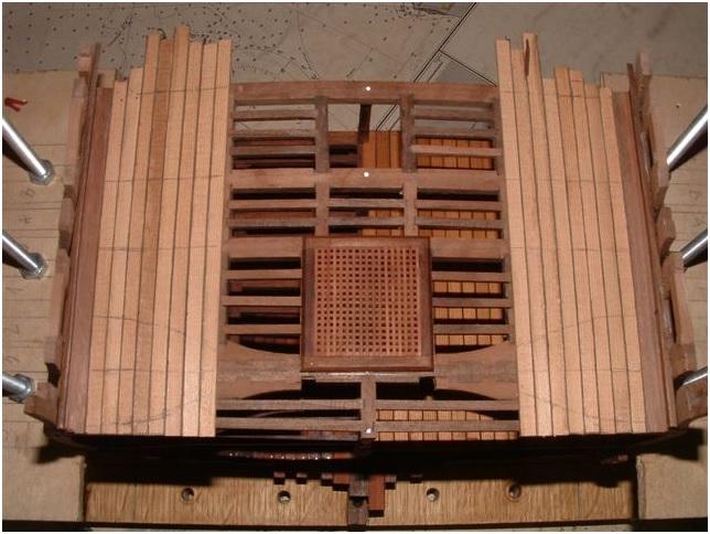
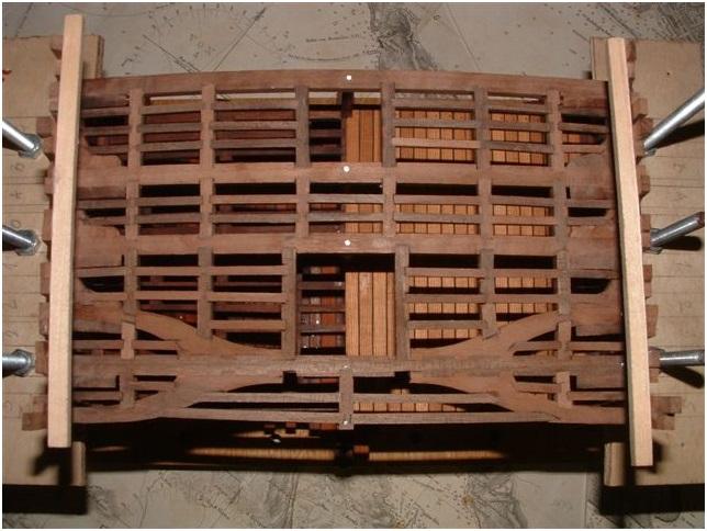
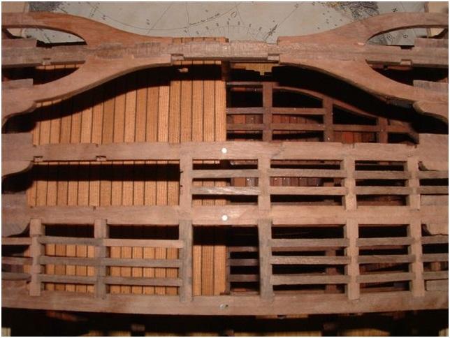
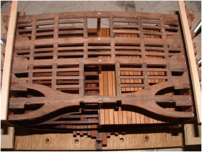
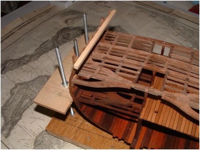
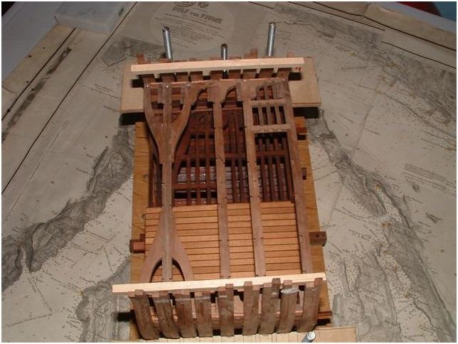
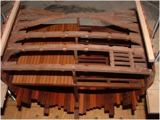
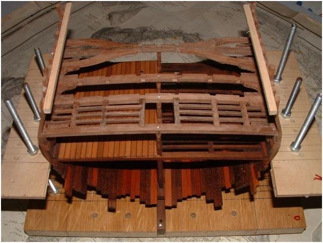
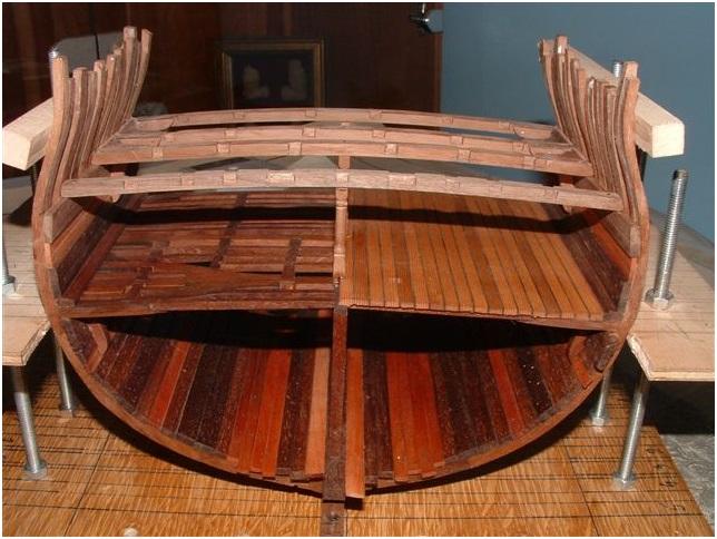
The complete Section model at this stage of construction Top view....the structure of the Gundeck is not oiled until now The very last Carling and ledges between axis 4 and 5 are installed
-
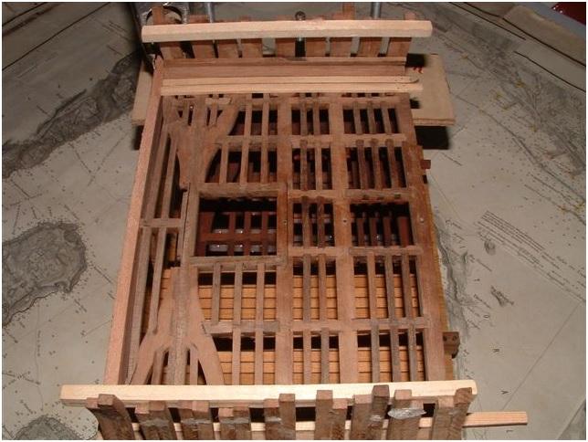
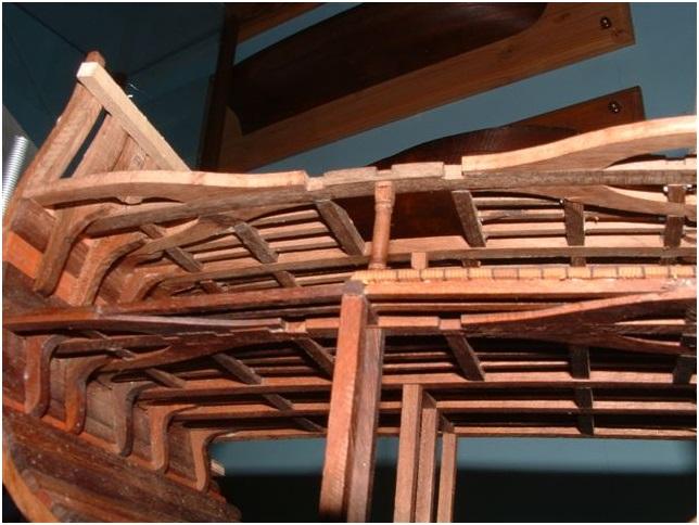
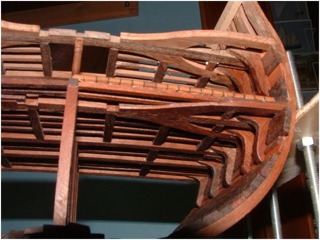
Some more photos of the progress of Carlings and Ledges...... I know it is a little bit boring to see more or less the same photos with only small progress,but I decided in the beginning to make here a detailed log! therefore I ask you to be a little bit more patient. the interesting posts with the deck-equipment, cannons and coppering of the hull will come (sooner or later) Only the carlings between the Beam arms and between axis 4 and 5 are missing The installation of the last Carlings and Ledges between the beam arms From this views to the top the complete structure of the beam, carlings, ledges and knees is visible
-
The first installed Carlings and Ledges between axis A and C and the finished ones between the first beams
-
Hallo Jerzy, like Russ mentioned already we take your time, and when ever you have time to start....do it.....a lot of fun and exercise. And the drawings will stay for free download whenever youdecide to start. Some more works are done on the Section with the installation of the other missing beams of axis 1 and 4,inclusive the hanging and laying knees And the installed beam arms
-
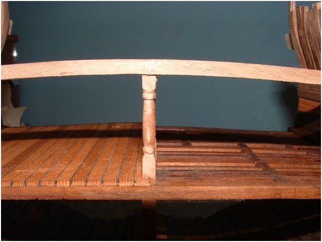
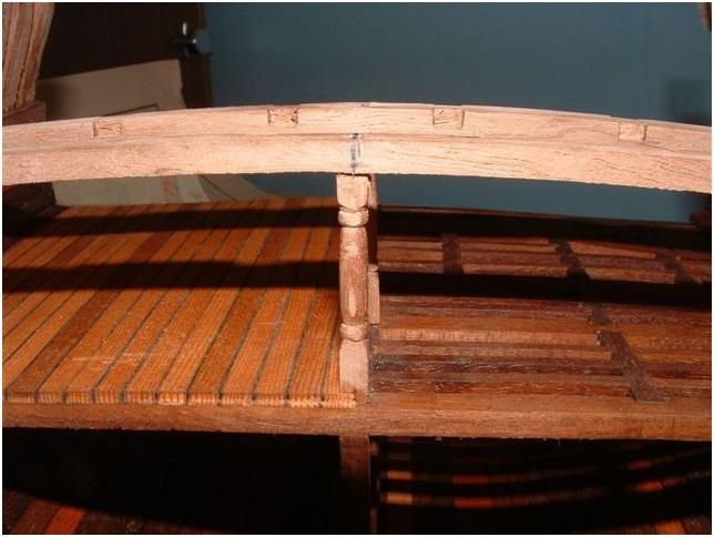
The first inside works for the Gundeck! The Gun Deck Stanchion should sit on the Lower Deck Beam and not on top of the Deck-planks,so the two planks in the middle should get slot / recess for the stanchion. On this photo the chamber is visible very good, check it on the drawing from Russ, the chamber of the Gun-Deck-Beams is bigger than this from the Lower-Deck-Beams. Here the Beam on axis C The same view in comparison with the Lower Deck In background visible the Beam on axis A with the already prepared recesses for the Carlings Bot Beams in the top view

-
After this "short" excursion about treenails on deck-planks back to the Section Model. Today only a short post showing the installed Limber Boards laying in the notch prepared in the Limber Strakes
-
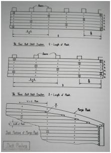
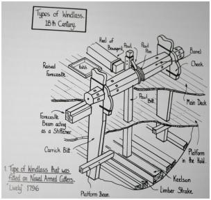
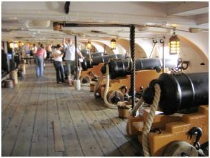
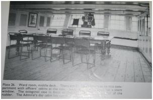
Russ, "One fastening per plank per beam" After a longer time of checking this in the different pulications I have,I received a suggestion, which is maybe different to your opinion. You are right, that in all important books (like Goodwin and Longridge) this "one fastening per plank per beam" is shown in sketches and drawings showing the Four or Three shift system, f.e. Page 58 of Goodwin. In the following text Goodwin is describing more in detail the different thicknesses of the planks, especially for the Gundecks, which has to take over oof course much higher forces. If you went through the book you can find several other sketches (not related to planking),but showing two fastenings per plank per beam, like on page 154 about "Types of windlass". So also Goodwin is showing both possibilities! Than I had a look at the different available photos of still existing ships: HMS Victory Main Gundeck (photo made by Jim and shown in Gallery) The Gundeck-planking is still the original planking and not changed by "wrong" restauration like at other ships we know. In the Longridge "Anatomy of Nelson´s Ships" we can find this photo at page 116 showing the ward room at middle deck,so not only the Gun deck of the Vic had two fastenings per plank per beam. This two fastenings per plank per beam you could also find partly on deck photos of the HMS Unicorn and also the HMS Trincomalee (ok, these ships are younger!) So I have the feeling that the use of two or one fastenings depends mainly at the shipwright who built the ship.In my publications the question is not answered.
-
Shadow, the ladder will hang only on one side "in the air", you are completely correct, but the structure is so interesting, so it should be visible in my point of view. Maybe some extra short planks at the area of the ladder could be the solution.
-
Hallo Roberth, It is no varnish......it is the original timber with a fine cover of a kind of fine mechanics oil with low viscosity. This oil is also like the Danish oil penetrating completely into the wood after some minutes and no oil rests is keeping on the surface of the timber. For example I had bad experience with linseed-oil in this regard which is partly not penetrating completely if the wood has a high density. But next time me and also Zeljko will try the Danish-oil which was mentioned a short time ago in an other thread.