HOLIDAY DONATION DRIVE - SUPPORT MSW - DO YOUR PART TO KEEP THIS GREAT FORUM GOING! (Only 20 donations so far - C'mon guys!)
×


Matrim
-
Posts
1,401 -
Joined
-
Last visited
Content Type
Profiles
Forums
Gallery
Events
Everything posted by Matrim
-
The two installed Limberstrakes, prepared with the longitudinal notch cut with the circular saw. The two (until now missing) Limberboards will be installed later on. Two Installed Footwaling next to Limberstrakes Thefirst three "normal" ceiling boards, one of the ceilings is still missing. The first levels of the Thickstuff installed

-
Some photos of the assembled keelson Longitudinal view of the keelson and the keelson from the top view you can see the iron nails with round head, which shall represent the iron bolts for connection of the keelson to the keel of the real ship. These nails have no structural function for the model!
-
Uwe: Yes they used metal fastenings all over a ship, but in model building the situation is entirely different. In a real ship, they did have a lot of movement in wood and metal fastenings of all types that degenerated over time. In a model, even with the best adhesives, wood still moves with changes in temperature and humidity and metal fastenings, regardless what they are, will degenerate over time to some degree, however small. Aside from the fact that the metal fastenings needed to hold the wood together in a real ship, there was also the problem of discoloration of wood by metal as it ages. In a real ship this is not important but in a model it could be. With metal fastenings, there is always some chance of this, no matter how small it may be. With wood or bamboo fastenings, there is no chance. But most important to me, wood fastenings will become a part of what they are holding together whereas a metal fastening will always be a foreign object in two pieces of wood. Use what you wish, but keep in mind what I am saying. Russ
-
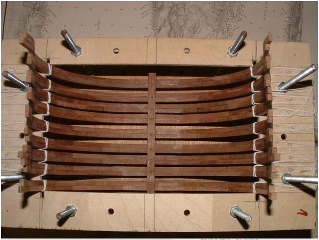
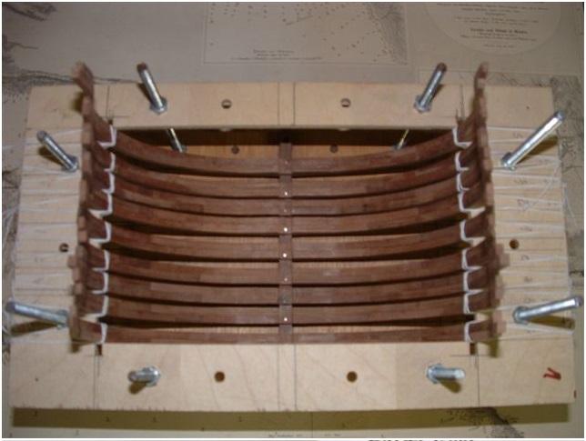
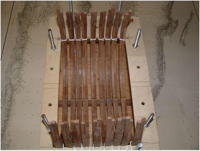
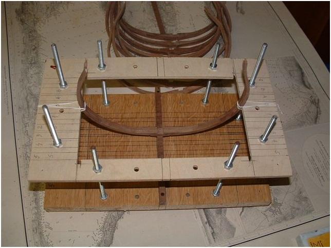
Some more photos of the construction: Installed frames 0, 1, 2 and 3 All frames installed in the jig, the frames are glued to the keel with a small additional nail through the Floor Futtock. It is important to nail through this part, if nailing on the side of the First Futtocks the glued joint between the two First Futtocks could "go open"! The same status of construction with a view from the other side


-
Warren, I will show the board level 2 in one of the next posts of this building log. In principle it looks like the board level 1, only with a smaller inside area, due to the fact that it will be installed in the same way at the height of the Gun Deck Beams. Also here at this level the frames will be fixed with a drop of glue and a cord-line. With this the frames are not moving and you have stability for the internal construction of the gun deck with beams, knees etc.

-
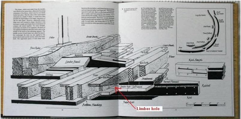
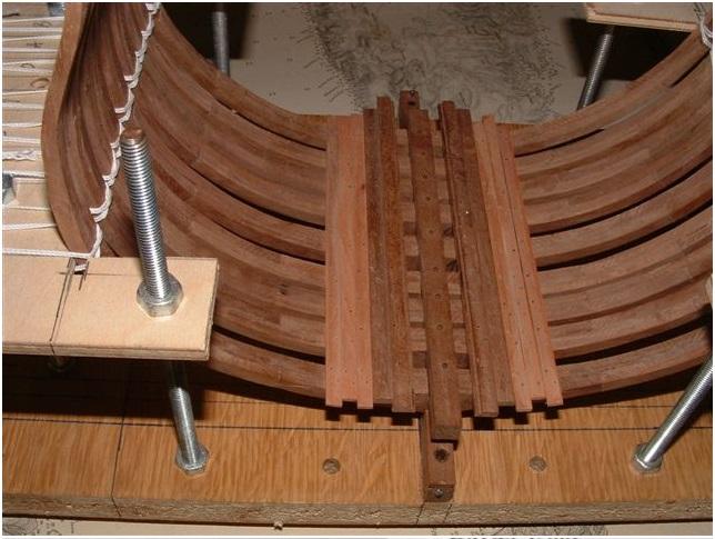
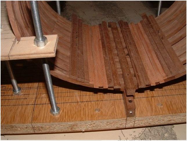
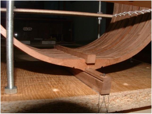
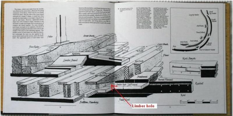
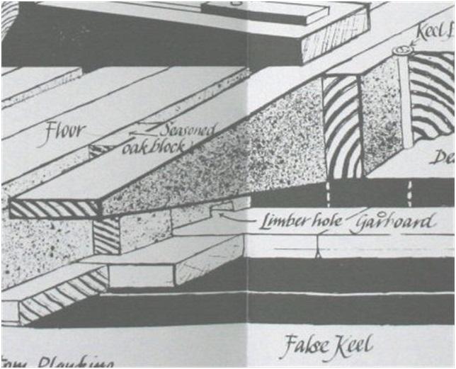
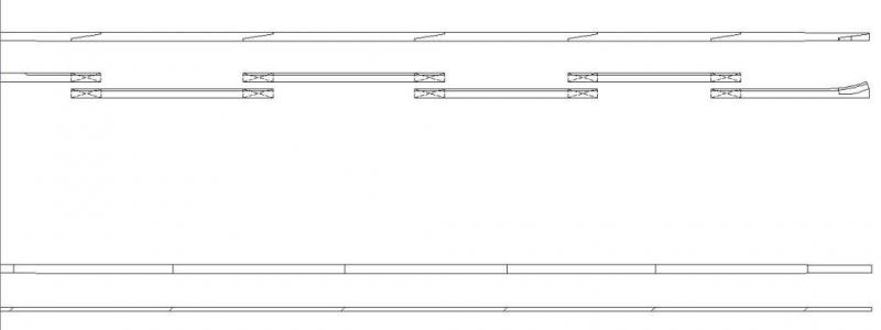
Hallo Russ, This kind of jig is very often used for complete "full size" models with the big advantage that all frames are really fixed until you finished the complete internal construction. No movements or widening of the single frames is possible. You are right with your interpretation of the small notches. These are the limber holes. In some (really not all) books these holes are shown as the lowest part for collecting the water and the dewatering of the bilge via the Elm Tree pumps. Have a look at the book from Dodds "Building the Wooden Fighting Ship" about which I made once a book review Here it is shown: And the detail in a bigger size: I do not know if this limber holes where at each ship, or only on bigger ones like the Dodds-74-gunner, only at a special period. In no book in my library about english ships of war this detail is discussed or explained. The Boudriot books about the french ships are describing this limber holes at most ships.
-
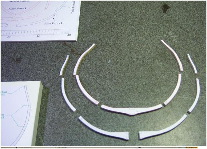
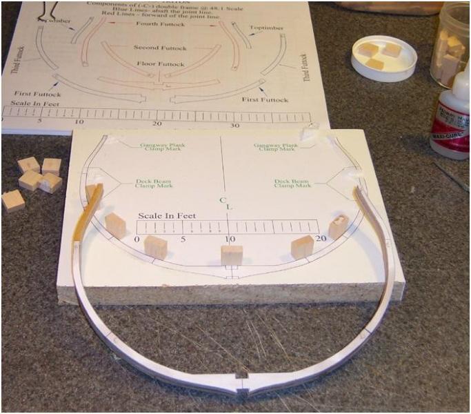
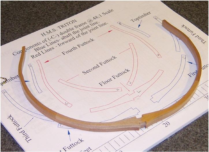
This is a re-post of an old triton log - please do not post against it as the original owner will not be replying - should the original owner no longer wish this log to be active then please get in touch and it will be removed. Additionally most of the times only the original posters post has been saved and so it will jump with regard to comments. In this particular logs case some of the image comments were tabalised and are often cut off as well. I'm finally getting started on this. I still have a lot of rigging to complete on my current project, but I was feeling the need to cut some wood this weekend, so I thought I'd take a crack at a sample frame member for this build. I probably won't really get into the build for another month or so. I started with the "C" frame assembly and got all the pieces cut out, sanded and assembled yesterday. I went thru all this pretty quickly (about 4 hours total build time), just to get a feel for what I was going to need to be thinking about for jigs and tools once I get started. It was a good exercise, and even this little bit of framing has told me that I will probably never build a POB hull again! I cut the frame pieces from poplar, just because I had some thin scrap laying around the shop. I doubt I would use this on the real build, but it's not bad looking. Certainly it's easy to work with cutting and sanding, and it's still pretty hard. It's jus I glued all the parts together with a thick CA glue. I was thinking this would be a quick way to throw this frame together, and I would use yellow glue for the real thing, but I'm pretty happy with how the joints turned out. It certainly makes for a quick The finished frame member, sanded to a 320 grit and finished with paste wax.
-
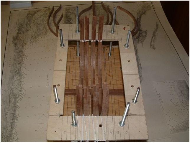
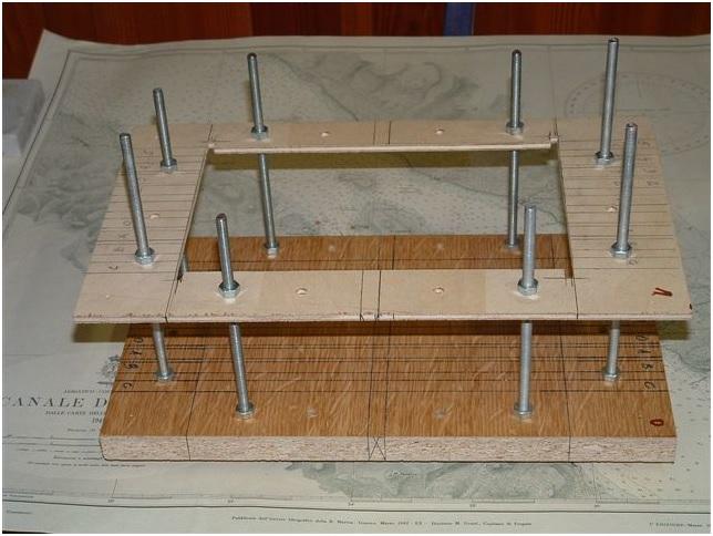
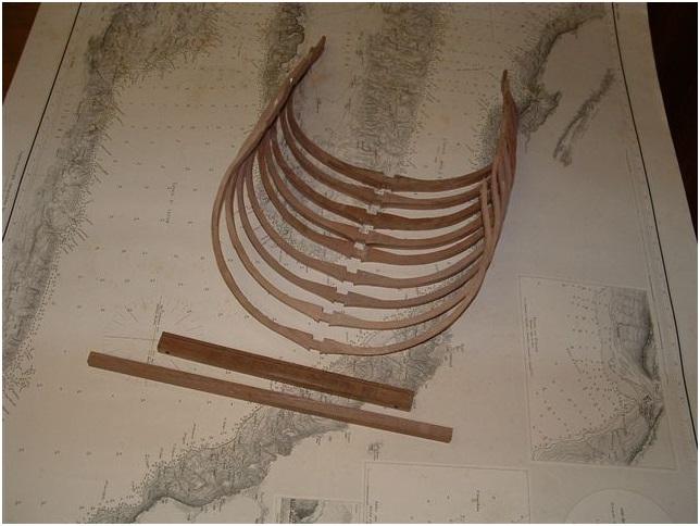
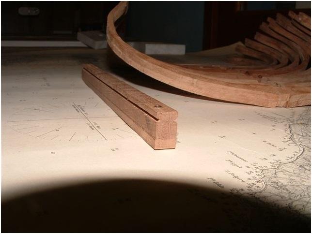
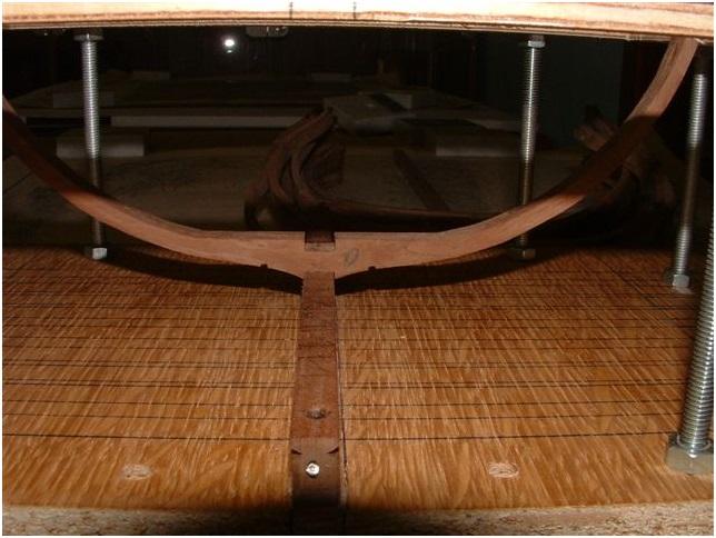
Mod Note - Some of the original Triton build logs have been saved and I will be reposting some of them up week by week. Please do not comment against them as the original authors have often moved on so will not be able to reply. If an original owner no longer wishes their log to be posted then please get in touch and the log will be removed. Also note that some of the original comments (usually attaboys but sometimes questions also do not appear Some time ago I mentioned to my friend Zeljko our Triton project and he was immediately very interested in this idea of a community built of a Vessel-section. Although he is not a member by himself here in MSW I printed out the plans and we agreed to make this built parallel and partly together. This was already some weeks ago. As times goes by he started earlier and me only last weekend. My description of my section built will follow. Here in this topic I will be able to show Zeljkos work for the Triton Section as a kind of building log, so you will be able to follow his construction works and see his way of construction methods. The basis for the built and installation of the frames is a "Helling-construction" (Helling-jig) with a strong basis (level O). On this basis the main lines are marked, like the location of the keel and the location of all nine frames (C to A and O to 5). A thinner first level board (level 1) is prepared with the same lines. This board should be installed and leveled exactly in this way, that the top of the board is on the same height like the lower edge of the Lower Deck Beams. Fixing and exact level can be reached and adjusted with several thread-screws and nuts. Each hole for the boards, where the screws will be installed should be drilled together in one pass, means that boards of level O, 1 and 2 (will be needed later on) should be clamped together and from the top the holes are drilled in one passage through all three boards. The prepared nine frames inclusive keel (shorter) and keelson (longer). Detail of the keel with the already installed False keel. Have a look at the rabbit..... in my following building log I will show how the rabbit could be done with an easy and very exact way..... The first frame number O installed on the keel, glued and additional fixed with a small nail through the Floor Futtock against the keel. On top of the photo the board level 1 is visable. The same frame shown from the top inside of the jig. In order to fix the ends of the frames a small drop of glue is used between third Futtock and board level 1 and in addition fixation with a cord-line. For the exact location it is now important that the marked lines on board level 1 are exact drawn and exactly vertical over board 0. Because of this the above mentioned info about the drilling of the holes for the screws.
-
Before you glue those in it would be useful to sand and possibly oil the inner planking. It will get more difficult to do once the beams are in place plus adding extra risk of knocking stuff out. Your choice though.. Joss.
-
Shipping from the US is quite reasonable and I dont think books are currently VAT registered in the UK so no tax either. I don't see a problem myself and if we do have to pay 'more' shipping costs then so do the Americans when ordering from Ancre.. Joss
-
Urk, shows how distracted I was as I did not even notice that this was out. Order in... Joss
-
I used black walnut for my beams and it does come up in a beautiful rich colour when oiled. Should look great. Joss
-
Cheers for the comments all. Fortunately I have time to consider and compare to other scratch builds the fore piece so I will probably follow that path with it. Joss
-
Dust collecting on Byrnes Machines
Matrim replied to stantona's topic in Modeling tools and Workshop Equipment
Oooo good tip. I used masking tape to try and seal the dust extractor to the saw - I thought it was the difference between a uk extractor and a us machine. Didn't think about a handy hoover attachment.. More added to the 'buy' list tsk tsk Joss -
Its all come out well - I think my favourite shot is the one taken very close to the edge of the cross section where you can see the outer planking is sitting perfectly tidily on the frames. Good job. Joss.
-
It is not a requirement. If you want less then buy less. Joss.
-
Done, I may attempt to drag some of the other stickies that were generated in the original forum. From memory there were some excellent ones on build order as well... Joss
-
"Okay, here is a rough set of dimensions to use for various parts of the model in the three scales. 1/48 scale Frames, no 61 bit (.039", 1mm), hull planking, no 76 bit (.020" .5mm), deck beams, knees, bitts, etc, no 68 bit (.031" .8mm), and for securing the frames and the keelson, a no 52 bit (.0625" 1.5mm) will do fine. 1/64 scale Frames, no 69 bit (.029" .75mm), hull planking, no 79 bit (.015" .4mm), deck beams, knees, bitts, etc, no 73 bit (.024" .6mm), and for securing the frames and keelson use the same 1/16" diameter bit as used in 1/48 scale. It will work fine. 1/96 scale Frames, no 76 bit (.020" .5mm), hull planking, no 80 bit (.0135" .4mm) deck beams, knees, bitts etc, no 76 bit (.020" .5mm) and for securing the frames and keelson, no 61 bit (.039" 1mm) Please, please, please keep in mind these are very rough and very general dimensions. This is a guide, not a set of hard and fast rules. So long as you are close, there should be no big problems. If you do not want to treenail your planking in 1/96 scale, that's fine, but if you do, you might want to use something a bit larger than no 80. Its the builder's choice." [copy of one of Russ's original posts on the subject of treenails]
-
That is the sort of thing that we do need to rescue as the Triton especially had a lot of great information collated by the original authors to assist.
-
They are both well worth the money.
-
Or you could go for a 'feature' - to show how they did not do things. Better to just do and redo though as most people get a peverse sense of satisfaction from thinking 'that tiny plank took eight tries and hours to get right and no-one will know'
-
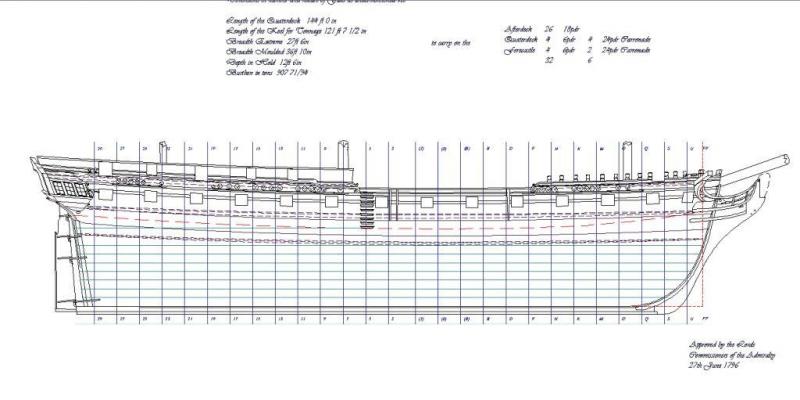
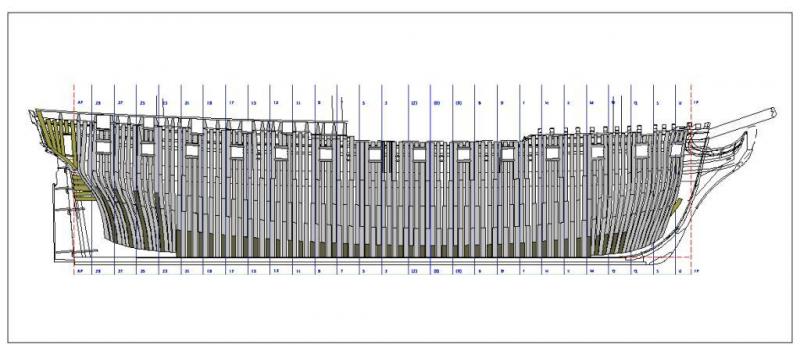
Rather than drone on about history intermiabley (which may not appeal to some) I thought I would bring the current state of the plans up to date. Some of these appeared in the log in the late lamented msw 1.0 as follows. None of these are particularly drillable. Sheer Next up the framing plan - No changes apart from re-arrangement of barricade type construction on the quaterdeck Then we have the first new plan. This is a framing plan to be used on the 'shipway'. Due to the innovative method of making the square frames follow a waterline (done on a whim) it looks a little like a large fish. This plan will be 'adjusted' as and when I get round to doing more detailed plans of the transoms, stern and bow details Finally we have the first working plan - this of the keel and false keel. I took some decisions here which I am uncertain about. The first is that I followed the Euryalus book in placing the keel taper over the cant frames only and not over the entire keel. I am not certain whether this should be over the entire keel length hence providing a smaller angle for a longer distance. The second decision was that what I read seemed to state that the false keel overlapped the joints of the keel. This seems to work well apart from the most forward piece which seems a little small to my eyes. Anyway comments on either welcome as always. Plans wise I am currently working on the rising wood then stem, stern and keelson plans. Joss
-
It's a good omen for the rest of the build that you can wield chisels so well. Joss
-
Nicely organised Joss
-
Everything looks solid and the keel looks nice, clean and tidy - which is a good sign for the build to come.. Joss.