Matrim
-
Posts
1,401 -
Joined
-
Last visited
Content Type
Profiles
Forums
Gallery
Events
Everything posted by Matrim
-
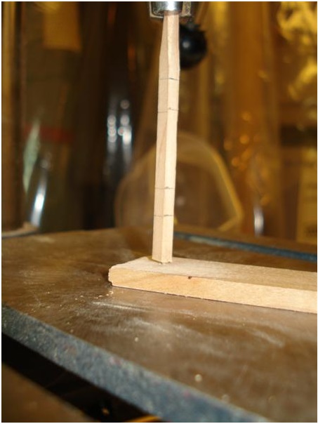
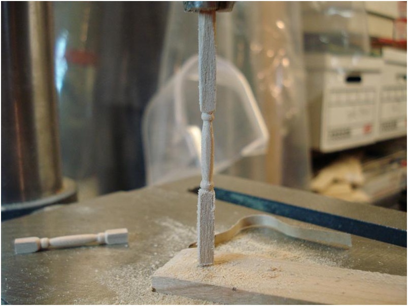
I made the support posts for the gun deck tonight and thought I'd post how I did it in case anyone is interested. I made a dead center using a brass nail in some scrap stock and cut out a piece of square stack that was marked to show where the tapers should be. The top of the stock was carved to fit into the chuck and a hole was drilled into the base to fit into the dead center. Here is everything chucked up with the dead center directly underneath the work piece. Here is everything chucked up with the dead center directly underneath the work piece. The dead center does a great job in keeping the work piece from wobbling while the piece is turned. Scott


-
Scott: Okay, I see. You really should think about planking the outer hull sooner than later. I know we have seen others do it the other way round, but I am a big proponent of outer planking first. I think it forces you to exercise extra care in every part of the planking both inside and out and that is a worth while exercise. Add to that it was how they actually built ships. You will like soldering. You are very detail oriented and that should make it easier for you to master. Its all about the details in silver soldering. The results will amaze you once you get the knack of it. Let me know if you have any questions. Russ
-
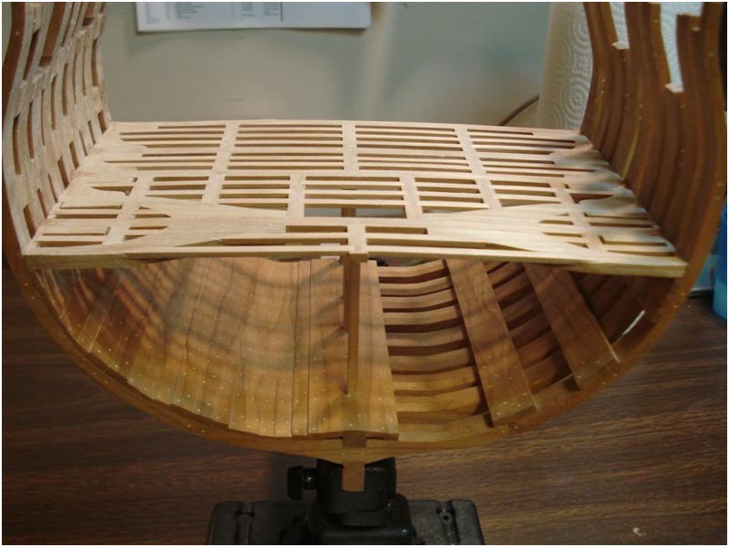
Here she is with a coat of finish as well as the waterways and interior side planking for the lower deck. She's a little dusty in some hard to get to areas

-
Scott: That's excellent. By the by, please remember that the bungs covering deck fastenings will not be more than 1" or so in diameter. We can have some variance here within scale limits but, as always in these situations, slightly smaller is better. At 1/48 scale, I would suggest .020" or slightly smaller for the treenails. Please let me know if you have any further questions. Russ
-
Scott: The only fastenings that were used from above were the ones in the deck beams. The ledges were fastened to the planks but from below. They would not be seen from above. That is a known fact. Thus, the only place you would see fastenings is on the planks where they cross the deck beams. As we have discussed elsewhere, you can use the single fastening in each beam that Goodwin shows was the standard practice back in the 18th century, or you can use the staggered double fastenings they show on Victory's decks in the present day. Either way will be acceptable. In either case, there should be two fastenings, side by side, at each plank butt. There should be no fastenings from above in the beam arms either. They were not really there to fasten planks to, but rather they are there primarily to stiffen the hull at that point. Russ
-
Thank you one and all! I was looking at your posts Uwe and have been thinking about the ladder issue. I'll plank a little under the ladder landing so it sits on planking. I've also been musing about fastening the planks down. I know this was discussed in Uwe's post but it doesn't seem to make sense to me that fasteners would only be used in beams and not in the ledges also. Everything I've seen indicates that only beams received fasteners but doesn't it make sense to also tack down to the ledges to prevent the palnks from creeking? Ledges are about a foot apart or so which is similar to the standard 16 inch on center used in the US for flooring supports in houses. The beams are many feet apart. Any thoughts on this? Yes you are right that we discussed this in my log and we came to a conclusion here, when I remember it correctly: The planks were also fastened from down up through the ledges with nails. Only sometimes smaller nails were visible also from the top of planks at the location of ledges .......have a look f.e. at photos showing the old gun-deck-planking of the HMS Victory..... ...but be carefull with the scale and the necessary diameter of such "small" nails at ledges. I would recommend not to make them! If you think about it, make a trial-planking with wood or only on paper, so you are able to imagine it better ......before you drill a hole in the "original" planking of your section
-
Scott Congratulations for your built so far !!! I like your clean and correct way of the execution very much..... It looks great already without oiling of the structure .....and it looks very good without the full inside planking, that you left only the thickstuff on the other side in order to show only the main structure of the vessel! I guess you will plank the deck on the same side on which you made also the inside planking? ......Only a remark for the the deck-planking: Do not forget that later on the stairs will be installed, so that the sideparts of the stairs are in th
-
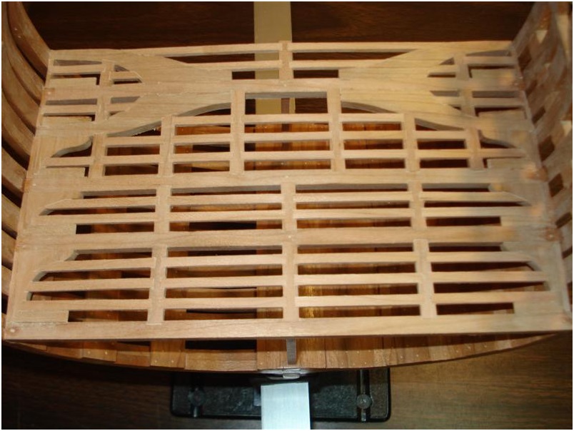
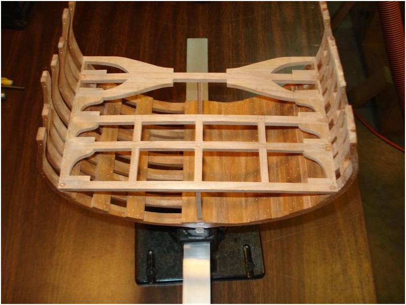
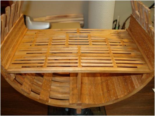
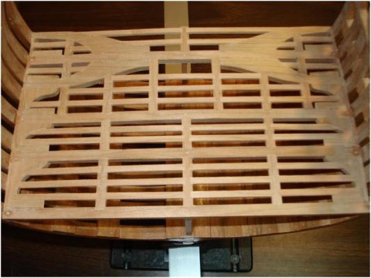
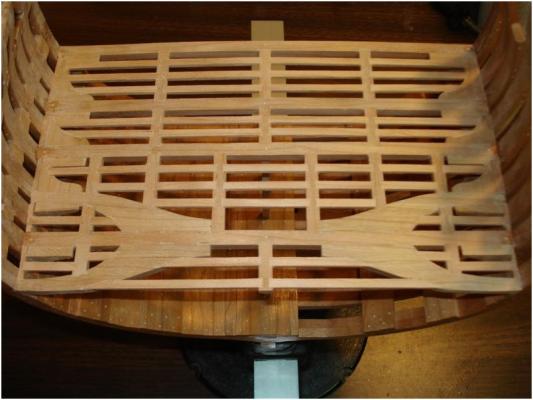
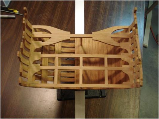
Thanks Jim! Here are the carlings and ledges in place (that's 90 ledge joints for those counting). All went well, now on to getting a finish on all of this before planking up half of the deck and moving upwards to the gun deck. Scott


-
Thanks Russ, Uwe, ZZ and Elia! I'll post more photos after I finish fitting the ledges. Don't worry about the joints ZZ if you are planking over them. No one but you and the Good Lord will ever know they were there. There is an old woodworking trick that you probably know of already but could try if you like. Take some white glue and work a little into the gap you want to hide (provided that the gap is not too large). While the glue is still soft, sand over the joint and the tacky glue will pick up the saw dust which will fill the gap and hide the defect. It is best if you use fine and old sand paper for this since some garnet (or whatever kind of abrasive you use) will also work into the joint and will darken the result. You might have to use an exacto to score the joint after the repair since this tends to hide the joint you want to show as well as the joint you want to hide. I'd experiment first on some scrap before doing this on your model if you decide to try it. Scott
-
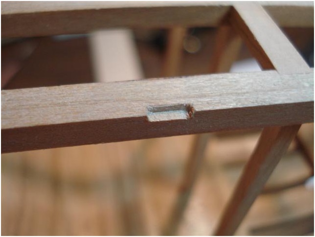
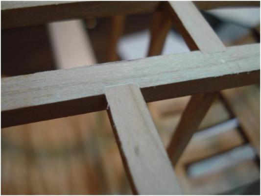
Hi Russ, I'm sure that someone who is more skilled than I could notch these beams before mounting but when I combine the camber of the beams, small errors that creep in and minor imperfections in alignment I stand by my decision to cut the notches in place. They are easy enough to do (as the photos show), the result is good and I have the peace of mind that only a try square can deliver in knowing that 90 degrees is 90 degrees. Scott
-
Scott: So long as you are using the deck framing plan to locate your mortices, you can cut them on the model or off the model. I would worry more about accuracy though when cutting them while they are on the model. For the beginners, it would be better to cut the mortices off the model. If you use the deck framing plan to locate the mortices, there should not be any problem cutting them off the model rather than in situ. You should remember that the mortices in the beams need to be deep enough to accept the ledge or carling. We went over this in another thread a while back. The half lapped joint is a short cut but its okay. If you are sure those hull frames on the starboard side are all faired up, then okay. Russ
-
Hi Russ, it must just be my camera angle that makes the frame look out of place. If you notice one side is blocked up since it will be planked while the other is only going to be planked on the inside to accommodate hanging knees and skid beam supports. Scott
-
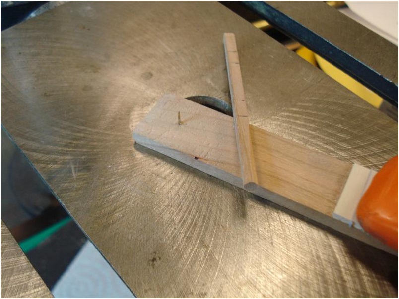
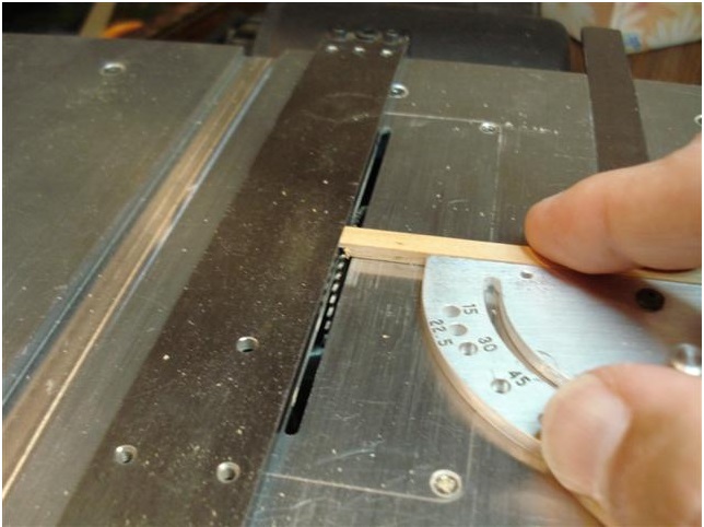
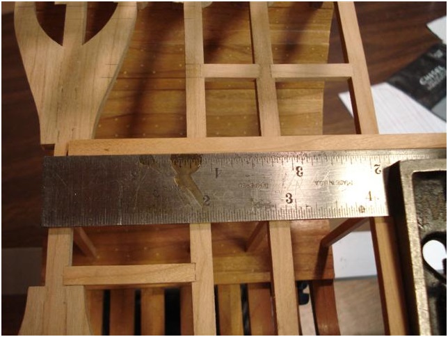
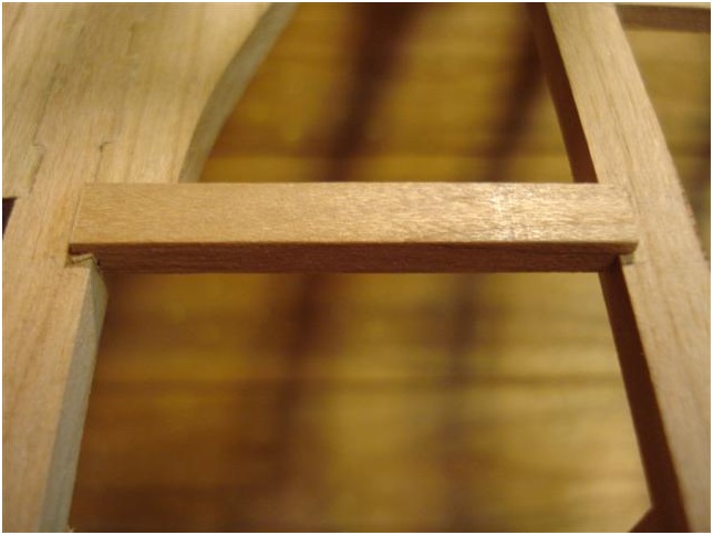
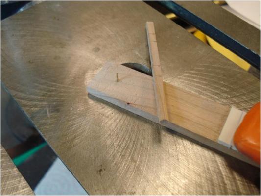
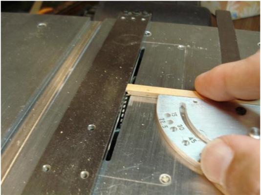
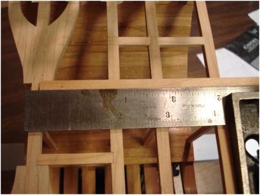
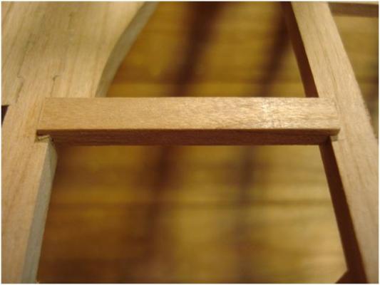
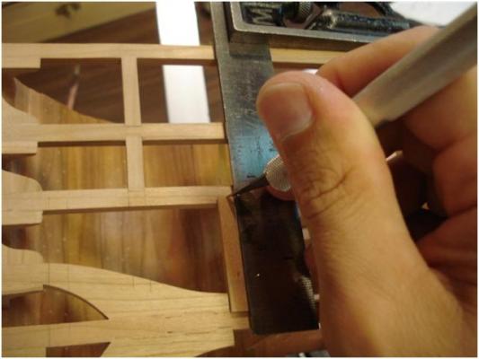
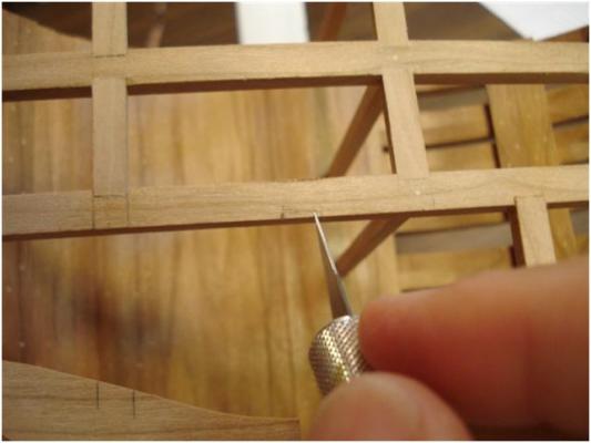
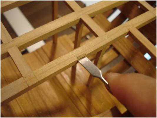
Hi ZZ, I debated about cutting the notches before or after installation of the beams and decided with the camber of the beams and the high likelihood that at least one notch would be off by enough to make the carlings etc not line up that I would cut them in situ. Here is the sequence for cutting the notches for the carlings and ledges that I am using. Make a notch in the end of an appropriate piece of stock Lay the piece in the appropriate spot and mark off the length needed paying attention to keeping everything square. Notch the other end and lay in place Use an exacto knife to scribe the areas to be notched. Cut the ends with the exacto knife. Use a sharp chisel to cut the long aspects of the notch. Clean up the notch with the chisel to the correct depth. Place the carling in place. Next weep bitter tears because a deck will cover all this work Repeat as often as needed Just kidding about that last bit , it is actually fairly fun to do and I have the utmost for Uwe and all of the others who have already made such nice looking deck framing. I must admit that looking at Uwe's framing made me decide to try my hand at this.

-
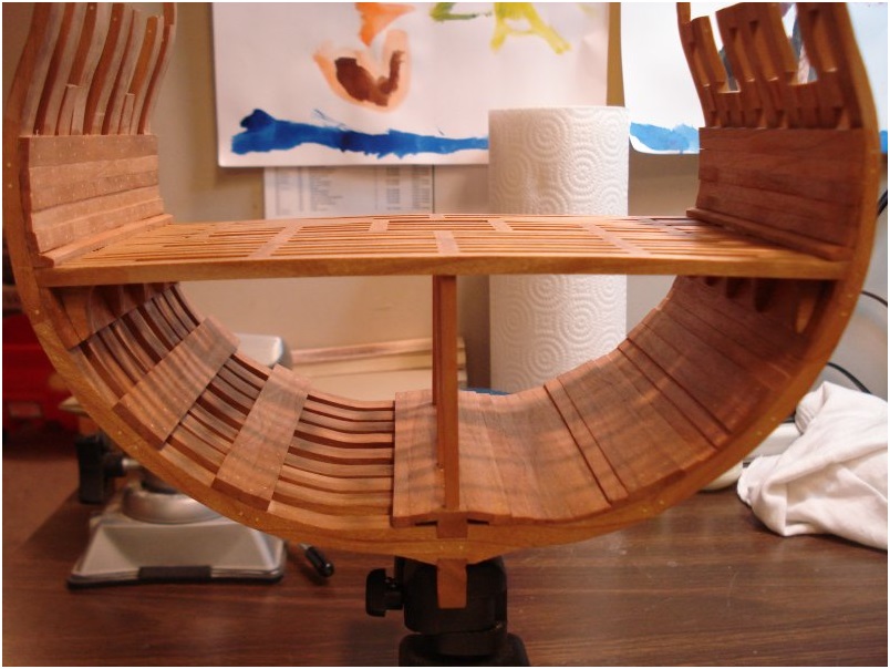
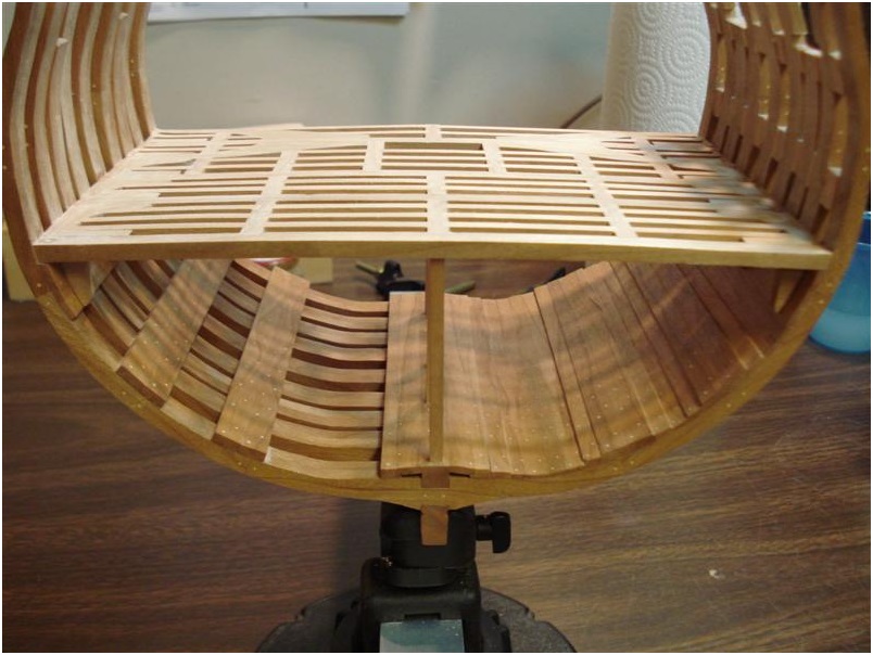
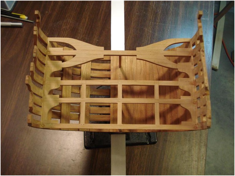
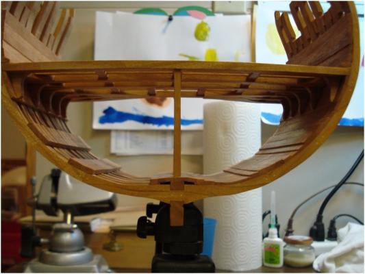
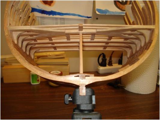
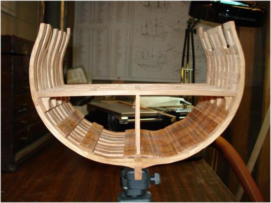
Here is what the cross section looks like as of today. The lower deck knees are all in and work is under way with ledges and carlings, so far so good.

-
Scott: Well, there's some good news at least then. I am glad you managed to get the frames on okay. You'll understand that even though this trick worked, it is not something I would recommend to anyone building this model. This might work on a cross section but on the complete build it will really pay to glue the frames and get them plumbed, and then drill and dowel them. This goes back to the entire reason for the cross section project ie to help prepare our rookies builders for the complete hull model. Russ
-
Hi Russ, You are absolutely right about the index dowels. The were drilled with the frames in place on a drill press. I disassembled everything to take the picture and now all are glued up in the construction jig. It was one of those "I'd better take a photo now or never" times . Scott
-
Scott: Please tell me you set the frames in place on the keel and then drilled the holes for those dowels. I'd hate to see the frames get misaligned doing it another way. Ideally, the way we want to see this done is to glue the frames in place and then drill down through the floor timber or 1st futtock into the keel for the fastening. Those dowels are supposed to fasten the frames to keel and not just act as locator pins for the frames. The dowels should not be more than about a scale 1" or so in diameter. This will be more than enough to hold the frames in place. Remember that the keelson will have to be fastened down onto the top of the frame floors as well. It is good to fasten the frames to keel and then the keelson to the frames. If you fasten the frame to keel through the floor timber to starboard and the 1st futtock to port, then simply reverse that pattern when fastening the keelson to the frames. By alternating the fastenings this way, you can make sure they do not interfere with each other. This will make the most of them individually as they work together to hold the structure together. Russ
-
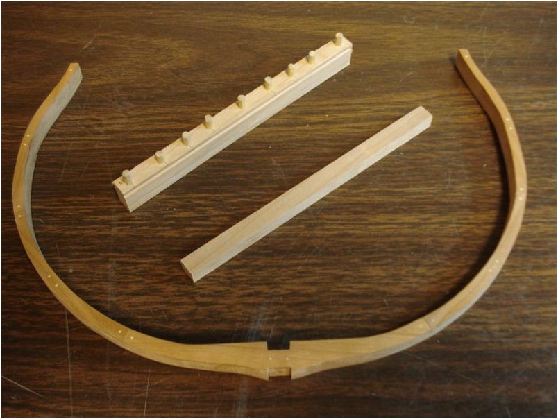
Just a quick update. The frame's fore and aft sides were finished with clear shellac prior to assembly. I hope to leave the starboard side of the cross section as a "skeleton" and these surfaces will be harder to get a fine finish on later. The keel and keelson are also shown. The 1/8 doweling in the top of the keel/false keel assembly is for pegging each of the frames to the keel. All holes have been drilled, next up is gluing the frames to the keel. Scott

-
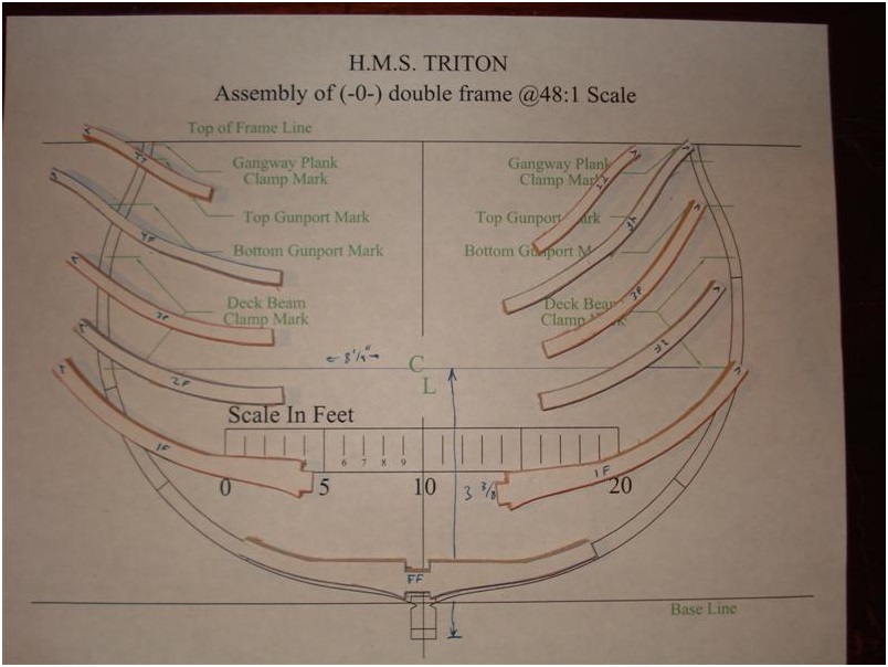
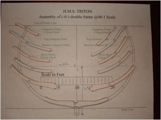
Scott: Those frame assembly drawings were designed to work with the assembly jig I posted. If you look at the assembly drawings they have reference lines at the top and bottom all the way across the page. That is where the alignment strips are positioned. Hopefully you will be able to get the hull together, but I cannot guarantee anything if you have not used some sort of assembly jig for the frames. Good luck with it. I wish I could help with this, but since you have got that far, there is very little I can do. For everyone else, I want everyone to look at the link I posted above and take heed. These plans were designed to work with that frame assembly jig. There is no way to know for sure that the frames will be properly aligned in assembly or when it comes to installation if you assemble them without a jig. We will be hitting this point VERY hard in the complete build to ensure we have as much success with the rames as possible. Russ
-
Thanks Russ for the link but the frames are all together now! I will keep this in mind for the next time though. The draftsmen and yourself did a great job with the drawings. It was exciting to see the frames take shape as they built up on the drawings. Each piece fit like a glove as they built their way up to the top timbers. I didn't clean out the notches for the keel/keelson because my plan/hope is to align all of the frames as a single unit. I'll then use a file to clean up the last few thousandths of an inch from all of them at the same time to try to ensure that they all lie exactly parallel to one another and perpendicular to the keel/keelson. We'll see how it works out... Scott
-
Scott: Please have a look at this frame assembly jig I posted a while back. This will solve all the problems of assembly the frames and gettting the pieces properly aligned. Please give this a try before you go much further. This is what I intended everyone to use. The only change I made from that photo was to add a section of keel in the notch where the frame will fit. I cut that keel piece off an extra long section of off cut from my keel so I know that it will be the exact same cross section as the keel. This ensures the keel mortice in the frames will fit perfectly on the real keel everytime. Russ
-
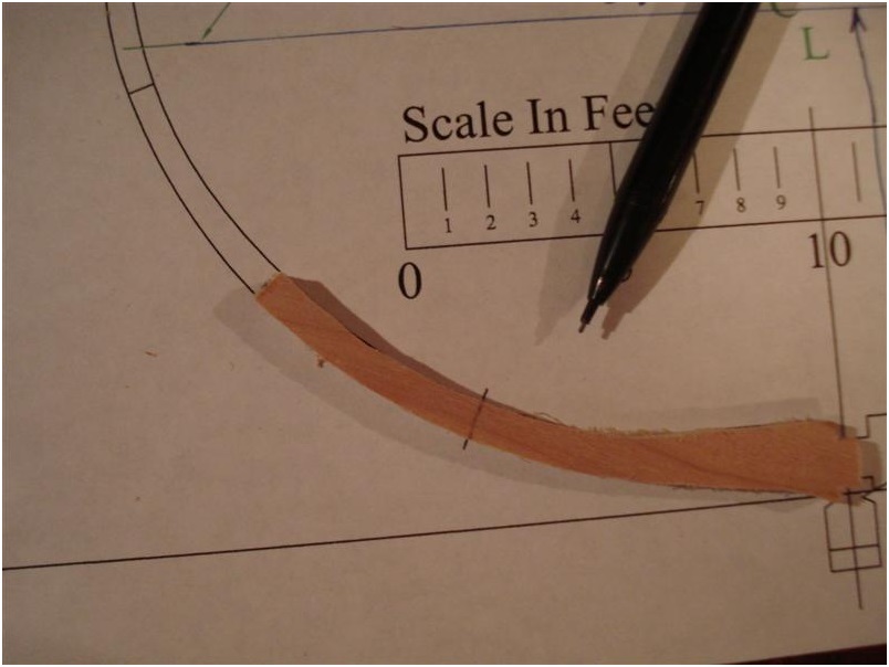
The next step was cutting out all of the frame futtocks and timbers. As I mentioned before, they can all be cut out of edge ripped ¾ inch lumber which saves a lot of work. I used a glue stick to attach the paper cut outs to the wood. Since I was working with strips that were only 3/4 inches wide, I had to cut out the paper futtocks just to the outside edge of the lines to ensure accurate placement onto the wood. The frame pieces were cut out and ground down to the edge lines using a sanding drum in the drill press. Since I didn’t finish off the cuts to accept the keel and keelson I had to use some sort of indexing system to align the first futtocks to the floor timbers. I made marks where the ends of the floor timbers should be and transferred these to the first futtocks. If this is not done then it is very difficult to correctly locate the first futtocks. I also found that the futtocks fit best if the end lines of the futtocks were just barely ground off. This made the top timbers touch the top index lines on the layout sheets. I should also mention that the glue from the glue stick released easily if the paper was lightly whetted with a finger dipped in water. Once glued together the final roughed out result looks like this. I should mention that most all of the builders of the cross section show their jig and then show the finished frames “magically” appear. Don’t be deceived, each of these highly skilled builders spent many hours getting from point A to point B. They are just being modest! I figure that each frame took at least an hour to just make it to this roughed out state.


-
Scott: Although I have mentioned this before somewhere, here is one little tip about making treenails. Do not worry with making a lot of them at once. When the glue is drying or you just clamped something up, or you are a few minutes from the end of the build session, make a length of treenails to pass the time. This will help fill in the time while you are waiting or while you have nothing else to do on the model. A little here, a little there, and you will produce a nice supply that you can always replenish next week while waiting for the glue to dry or the paint to dry or whatever. Scott: I should add that I agree entirely with your opinion of treenails. They do add strength. That is one main reason why I am such an advocate of their use. That they can be made to look good is a secondary consideration, I think. They are there to help hold things together. The treenailing of the frames may or may not be seen in the finished model, but the fact they are there will mean that the frames are well built and long lasting. On my cross section a few years back, I treenailed every part of the hull. The first thing I noticed was how solid the hull felt in my hands. The second thing I realized (and this is most important) is that nothing on the hull was going to come apart. The hull is glued together and the treenails are glued into the wood planks and frames with the same glue. The structure is all tied together and working together. That is a great relief to know. One treenail will not do you much good in a model. Several hundred will collectively have a great affect. Russ
-
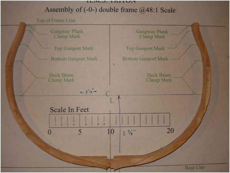
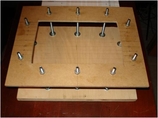
Mod Note - Some of the original Triton build logs have been saved and I will be reposting some of them up week by week. Please do not comment against them as the original authors have often moved on so will not be able to reply. If an original owner no longer wishes their log to be posted then please get in touch and the log will be removed. Also note that some of the original comments (usually attaboys but sometimes questions also do not appear I’ve never built a plank on frame model before so I’m looking forward to giving it a try with this Triton Cross Section. I plan on using cherry for the frames and other structural supports with holly for the decks. My hope is to finish off one side of the model completely and leave the other side as a skeleton to show the structural supports. Upon studying the plans, it looks like all of the cherry pieces are less than ¾ inches in maximal width so all of the frame futtocks will be able to be edge sawn out of a standard ¾ thick piece of cherry. This will keep the grain pattern to a minimum. The wales might be made from stained cherry with an eye kept on cherry’s nasty tendency to be blotchy under a stain if not evened out first. Some experimenting will be in order to see which finishes will work best. The first step was to build a framing jig. I’ve copied Uwe and others with the two level jig supported with 1/4 inch carriage bolts at several locations. The slight bowing out of the cut out is to accommodate the mid ship frames which follow the same fairing pattern. The top piece is at the level of the lower deck and is made from ¼ inch MDF. All of the lines were transferred off of the plans and scribed with a T-square and triangles. I have to thank Russ and the draftsmen for the excellent job that they have done in producing these plans. They are detailed and very accurate. Here we go! Scott
-
Nice, also has the advantage of not risking 'stain' if using a caulk mixture. Joss