HOLIDAY DONATION DRIVE - SUPPORT MSW - DO YOUR PART TO KEEP THIS GREAT FORUM GOING! (Only 20 donations so far - C'mon guys!)
×


Matrim
-
Posts
1,401 -
Joined
-
Last visited
Content Type
Profiles
Forums
Gallery
Events
Everything posted by Matrim
-
I used a razor glued between two bits of wood so the wood would hold the angle. Repeated 'scrapings' work well plus by the amount of razor blade extending between the two wood pieces you can control depth and angle. Joss
-
You are in, give me a shout if you cannot find the plans set. Well done for starting and enjoy it. Joss
-
It is not to difficult to make them - some in the past have turned them in wood to avoid having to get a metal lathe. This may be too much so if buying I believe the Triton held 9 pdrs on its primary deck (at least that is what the cross section plans show).. Joss
-
Good work, I always find once you start getting the deck beams in it starts to feel like you are progressing after what always appeared to be months of frames and more frames.. Joss
-
Ack! I never considered using a mill to cut out that joint before. Saying that on my next model it is likely to be slightly angled so it will still be by hand but for the cross section it is a great idea. Joss
-
Looking nice and spending your time allowing the glue to set will certainly help. Joss
-
In case anyone would like to see the British Navy failing to sink a wooden Napoleonic 74 Combination of most of the shots Silent shots 1932 http://www.britishpathe.com/video/the-132-year-old-implacable With 'Queens English' commentary http://www.britishpathe.com/video/implacable-to-the-end Joss
-
On treenails it depends very much on the sort of effect you are after. If you are extremely accurate with your treenail placement then a very dark colour can be very striking. If you are not that accurate then the very dark colour just draws the eyes to any mis-placed nails. If this is the case then lighter is better (less is more..) So look at what you like visually, effect on others and potentially placement accuracy. Coming along nicely though. Joss
-
Cool, - small gaps (especially with planking) can be covered by sawdust and glue to be almost invisible. Not so easy to cover frame issues though. Are you intending to use the toothpicks for treenails?? if so standard bamboo is easier to get to size and when stained because the end grain is showing it soaks up the oil and appears 'dark' automatically. If not then apologies as that will not have helped. Joss.
-
Nice - holly is really nice for deck planking. Plus this is 'easy' planking so it should go nicely. Are you planning on caulking? though there are a multiplicity of methods of doing that.. Joss
-
Thanks Ed. I have the full plan set though for the progress book I only have her sister ship (the Proserphine). Joss
-
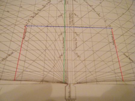
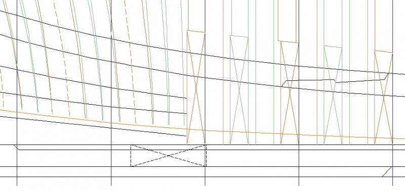
Well after a lot more reading (In Ed's book p208 & p209 also define the two lines) I think I have finally got my head round the line. For those who are interested (and most will probably know of it already) here is the relevant Steel shot The red and blue lines cover the 'inverted u' I was incorrectly looking at. The red is labelled 'Rising Height' and the Blue 'Rising Breadth'. The key line though is the green line which is labelled the Bearding line. Anyway this is not marked on my body plan so initially I considered using the short section of the bearding line that was shown on the framing plan - and taking a line across to the body and back engineering it from there but I noted Ed's wise words to not trust the line so much so tried another way first. I re-referred to my Steel and firstly used the table on p10 of the 'Tables forming the bodies' - here nothing seemed to match the expected bearding value but it did provide cutting down line heights at specific frames.So I added these to the profile and was pleased to see the resultant curve matched my cutting down line almost exactly. The next relevant page for my 32 gun frigate was Folio II this listed the rising wood to be 1' 6'' broad for a 32 gun ship. Looking over my plans the half breadth showed a dotted line where the cant frames would be at either end of the ship. Measuring this came to 5.something small mm (give or take a 10th of a mm). Pushing that up to full scale and then to inches gave me a figure of 1 foot 7 inches. Not the same as the Steel but it would match a 36 gun ship. As a rule you would expect to take the plans over the book so I resolved to plot both and then compare them to the existing cant frames start points. The end result of this was that the 1' 6'' was lower but the 1'7'' matched the fore cant frame lines exactly and was close to the rear cant frames. This I think means I have the correct line and has also validated the frame start points from the framing plan. Anyway to show the rear (where the line from the cant start frames was visibly higher) Here you can see the gap between the current cant frames markings and the washed out orange line which represents a bearding line drawn at 1'7'' (the 1'6'' was of course lower still). if that is not obvious then it is the fourth full line that covers the entire width of the image from the bottom I will probably adjust a few more of the rear deadwood lines now - I will possibly make them all straight so they are easier to cut, these again are not marked so I am guessing with all bar the new bearding and the cutting down (which can be seen easier with the obvious joint) Anyway hopefully that is actually correct. As always if not shout. Thanks to all those wise heads who are helping me keep to the straight and narrow. Or at least trying to. Joss
-
Looks nicely done - the wood choice is making a pleasant colour as well Joss
-
Urk - thanks for the adjustment Ed - back to the drawing board and books for me.. Joss
-
They look magnificent, great job.
-
John's work was exceptional really. I am still open mouthed looking at how smart and exact his wood working is..
-
Additionally I have just used the info provided to cross reference my copy of Steel - I had not realised that inverted U on the body plan was related to the Rising Wood.. so I will switch to getting a more accurate line in and adjusting my square frames as well. Joss
-
Thanks for the detailed info. This proves how useful the Naiad and Euryalus book/plans can be as I am using them as a 'sense' check on the drawings. If my own show a noticeable discrepancy with either of those plan sets then most of the time I can assume something has gone wrong. Fortunately once I get my head round things I do not think this is a drastic one to correct (time consuming perhaps but not drastic) Many thanks to the pair of you for taking the time to provide such informative response/corrections. Joss
-
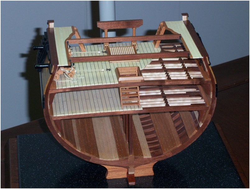
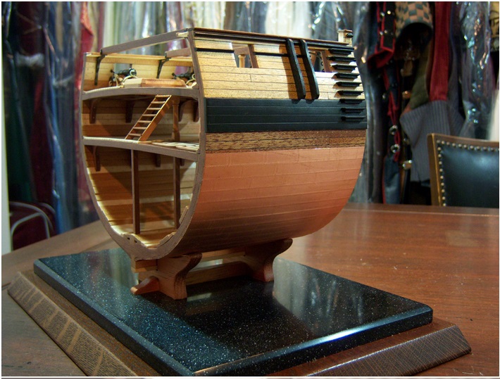
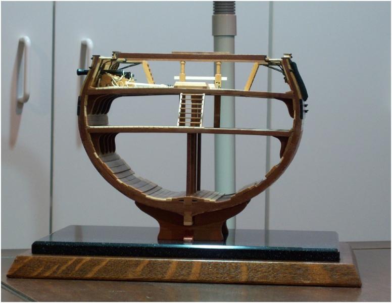
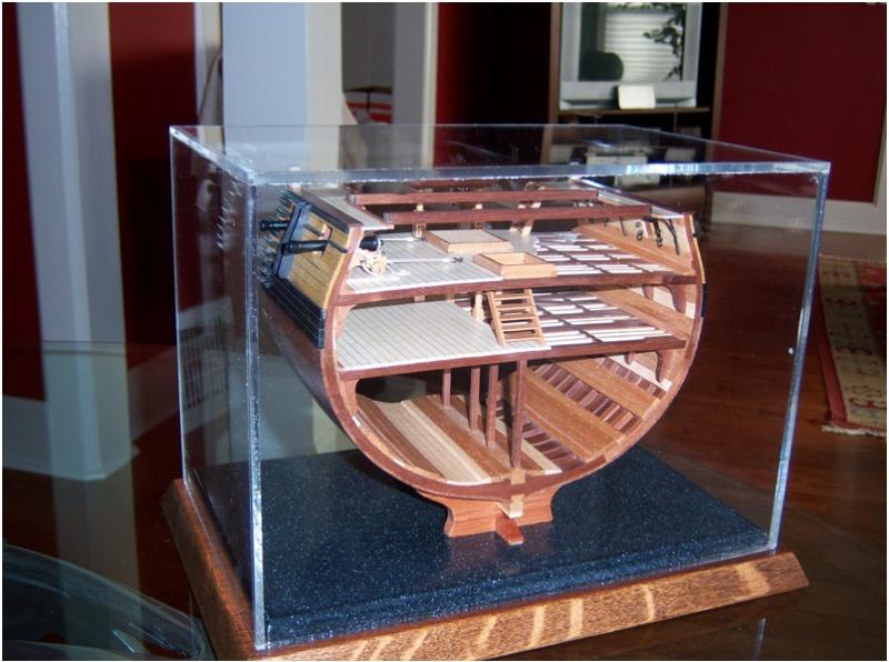
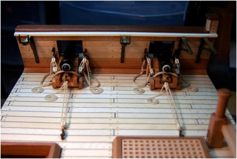
Complete!! Feels good to have finished her at last. With the gangways complete, and half the hull coppered, I finished a little display stand to show her off. I even took a crack a making an acrylic display box cover for the stand. Gonna take a little more practice to perfect that. There are a lot of bubbles in the joints on the acrylic, but not bad for my first time. All I need now is a little brass nameplate! Once again, I want to thank everyone who contributed to this project. To all of you who invested your time to create the drawings, monitor the build logs and give your input, all those who came before me and took the time to post thier build logs, and all of you who offered suggestions and support, I thank you! You've made this a great first project, and made me a convert to scratch building! ...now I'm off to finish rigging my first model. Lots more to learn about rigging before I can tackle a complete scratch build, but I'll be back for the complete Triton build before too long!

-
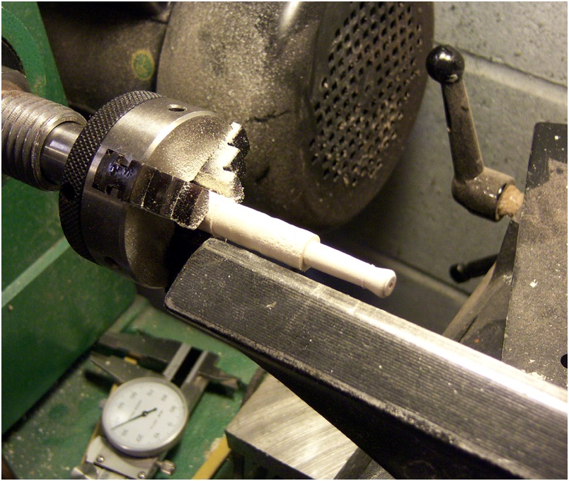
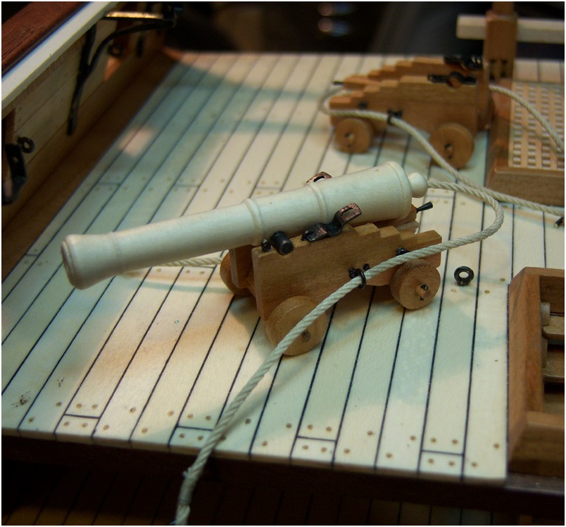
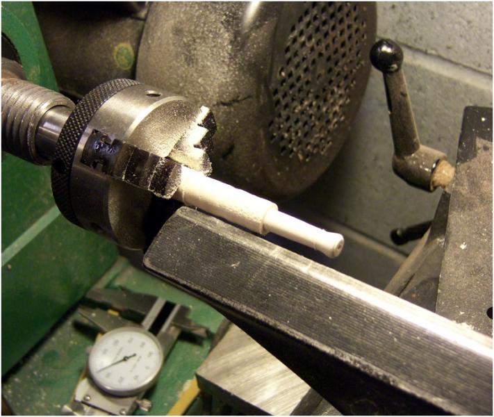
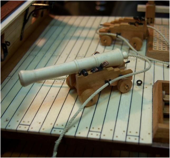
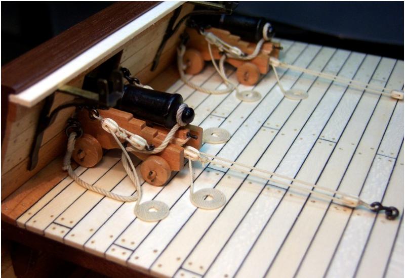
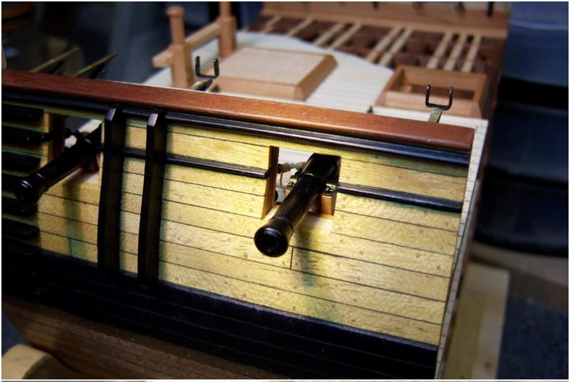
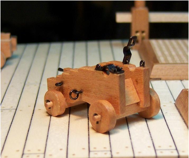
Got the cannon barrels turned this past weekend, and the rigging completed for the cannons. I turned the barrels from Holly, which works very nicely. It takes a fantastic polish! After turning them , I dipped them in black leather dye a couple times and then gave them a thin coat of clear satin lacquer. The alcohol in the leather dye raises the grain in the wood just a bit, but that just gave it a bit of texture, and the result looks pretty good. The rigging turned out about as I expected. The rope work looks good, the blocks I'm not so happy with, but so far it's the best I've been able to achieve making blocks. The rope was made on a homemade ropewalk using thin cotton quilting thread. 4-strand ( about 1" dia ) lines for the running tackle, 16 strand (about 2 1/2" dia) for the breech rope. The rope coils are made off-line as a separate item from the line coming down from the block, and then I just glue the end of the line to the deck, cut it off nice and square, and then glue the coil down at the end of the line, trying to get a clean joint between the two. Sometimes it works nicely and you can't really see the break unless you really look for it, other times it's too obvious. I've not found a way to make a coil that small on deck, using the tail end of the line as it should be.
-
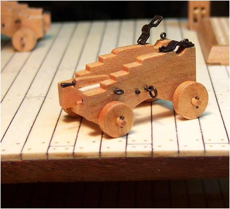
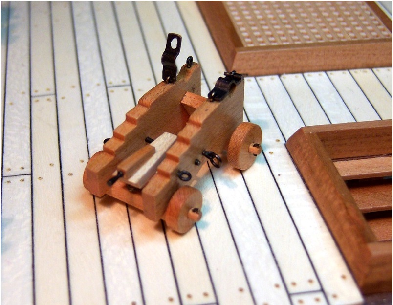
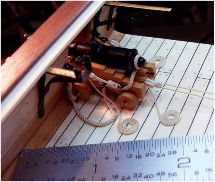
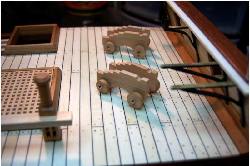
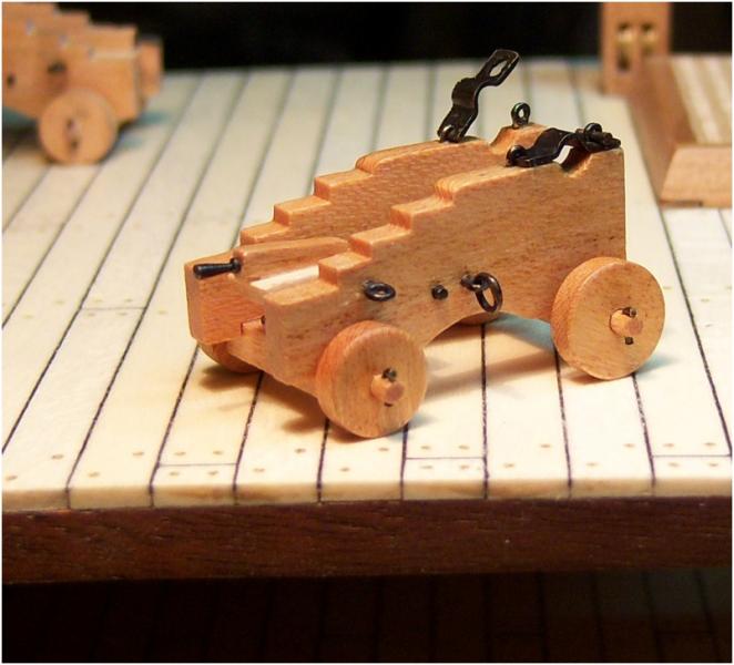
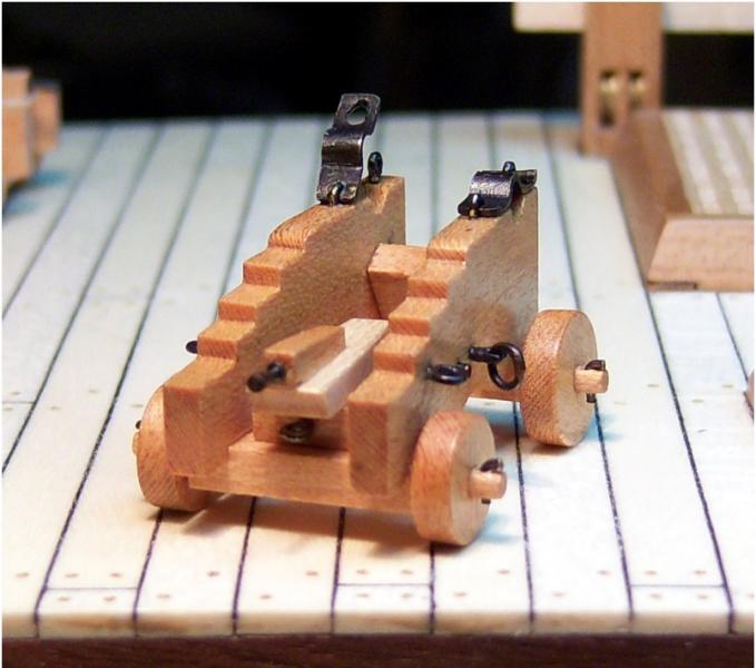
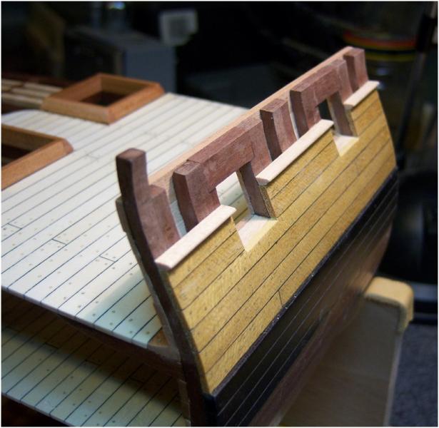
I decided I better get the cannons completed before I finished the gangway or it would be difficult to get them rigged. The plans for the cannon carriages are excellent, and I had no problem getting those built this week. I haven't tackled making the barrels yet, but that will be this weekends work. I used cherry and maple for the carriages, and you can see the results below. I'm quite happy with how they turned out. The wheels are functional, and so are the brackets for the trunnions! The little tapered pin comes out so I can place the cannon barrels later. I hadn't intended to put this much detail into it, but I was having way too much fun. I also got the brackets for the gangway completed and glued in place.

-
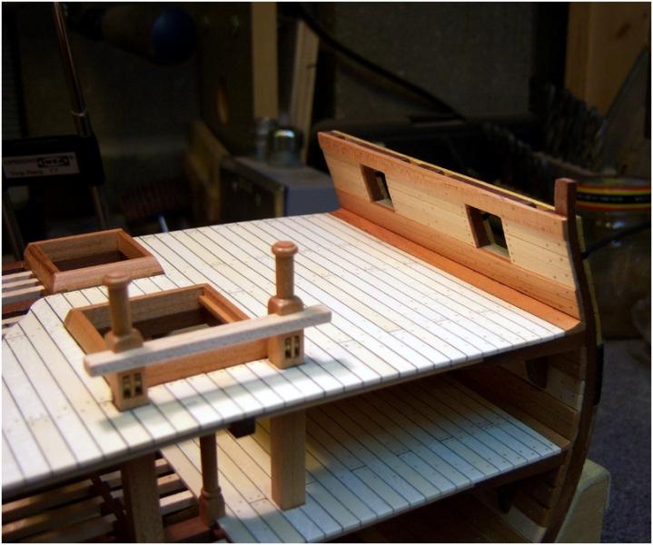
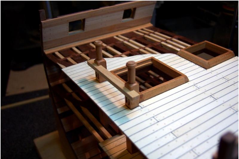
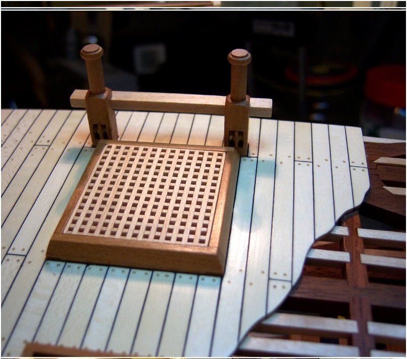
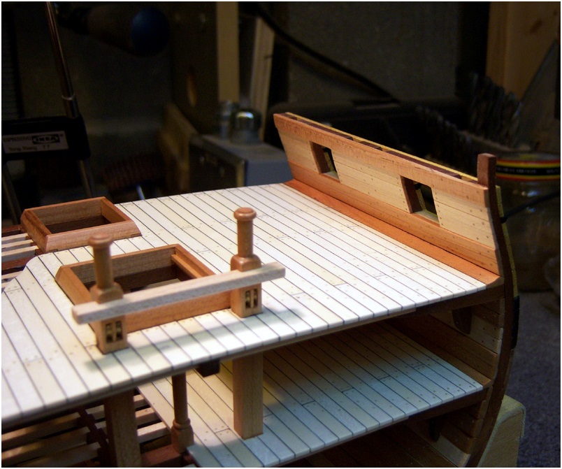
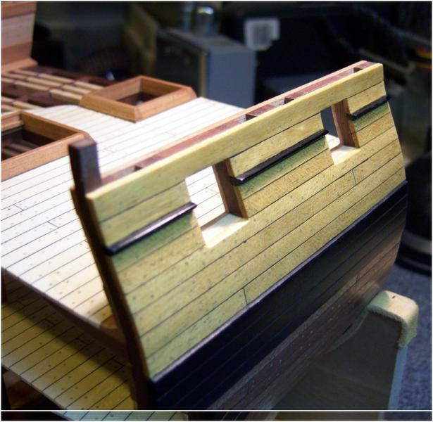
Uwe, each plank was cut individually to a curved shape at the exposed end, and then glued in place. It's a bit time-consuming to get just right and get a smooth flow across several boards, but the end result is very pleasing. I was looking for a good way to extend the decking over to the gangway ladder and keep a nice appearance, without covering too much of the framing. This technique seemed to work well. I don't recall where I stole the idea from, but it was somewhere on this site, I'm sure!

-
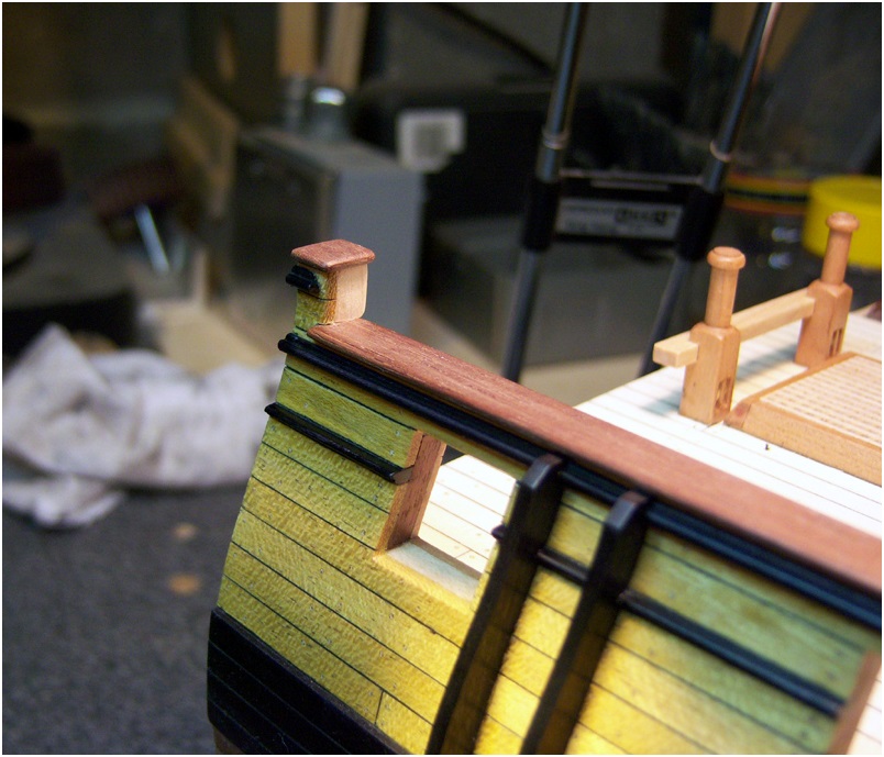
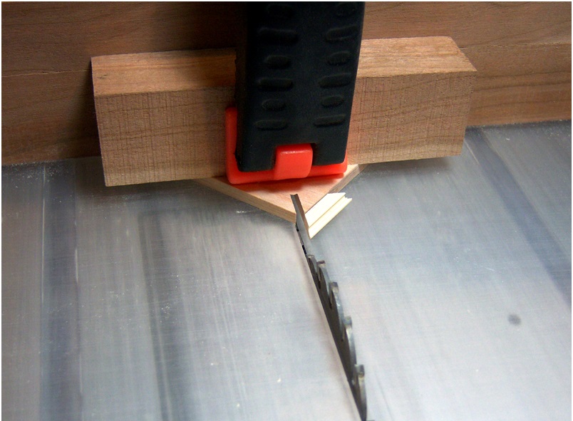
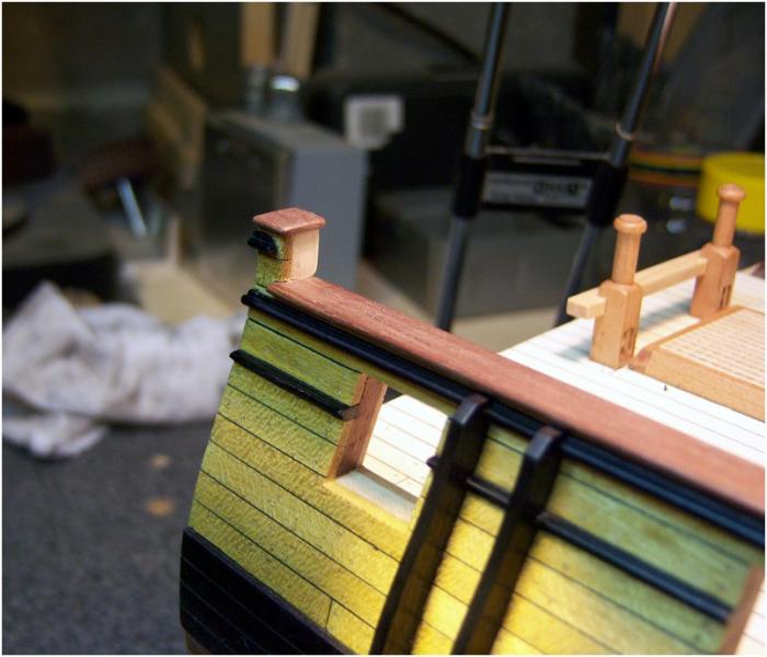
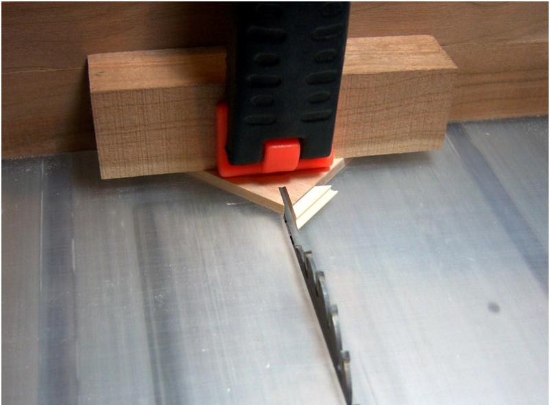
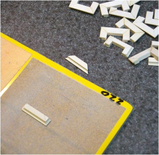
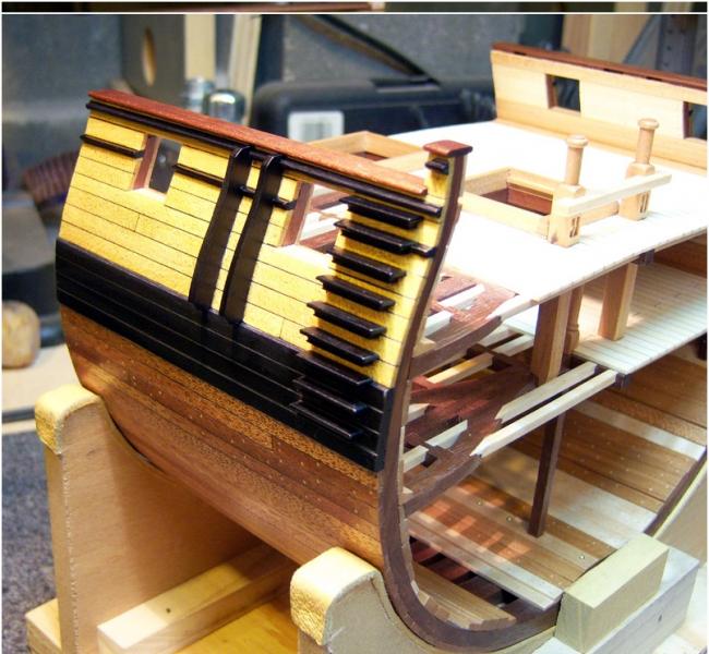
...and to finish off the exterior, I give you entry steps, sheer rail, and the final moldings! The step were a challenge. I thought about this quite a bit over the last few weeks as I was coming up to this part. I didn't want to just use a beveled profile, I wanted some detail. and I knew I could get it by making strips of molding. The challenge was getting the profile to follow around the ends of the steps. I suppose I could have carved each step, but I thought that was a a lot of work, and I wasn't that confident of my carving skills to repeat it 18 times with any consistency. I decided to just miter the ends to get the profile and make a "picture frame" joint at each end of the steps. Making a micro-sized miter jig for the microlux saw allowed me to make miters in the ends of the steps, and then I just glued the miters together using CA adhesive. The end pieces were kept extra long so I would have something to hold onto, and then after the glue was set, I just cut off the excess.

-
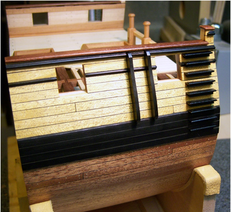
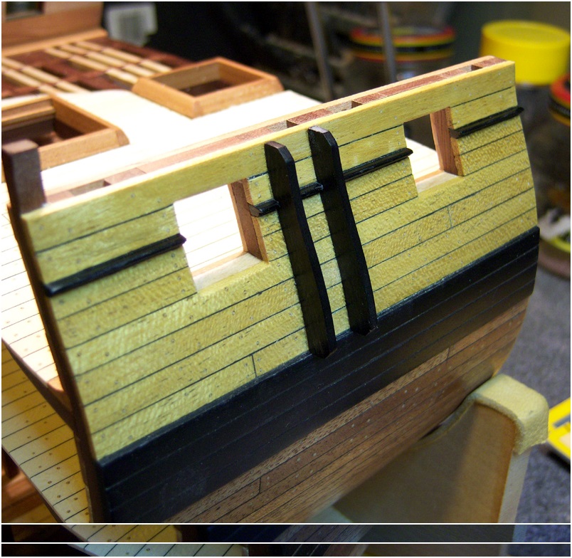
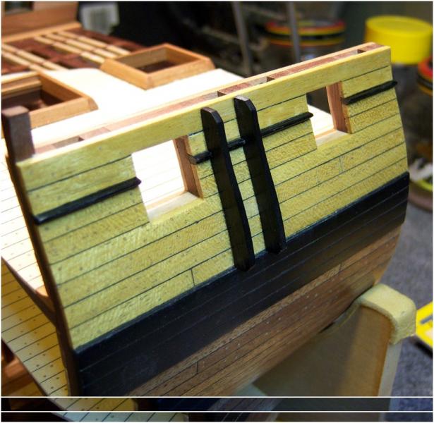
The exterior planking around the gunports is complete, along with the moldings and fenders. I made the moldings and fenders from holly, which works well for this small detail stuff. I think hard maple would have worked well also. Either one takes the black leather stain very well. The holly shows a little more "figure" thru the stain, but unless you can see it up close in good light, you wouldn't know the difference.
-
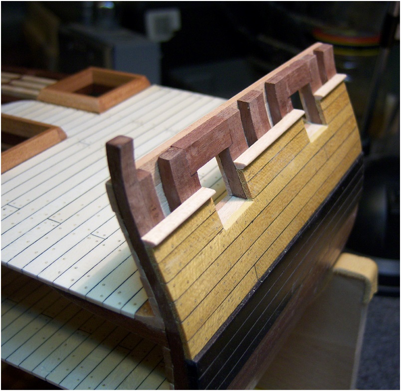
Next up I completed the interior planking around the gunports. I made big oops here, as the gangway clamps should have stopped below the tops of the frames to allow for the gangway decking. You'll see later on that I was able to chisel the clamps down before I placed the sheer rail. That's what I get for staying up too late to try and get things complete, when I should just go to bed!