
GGibson
-
Posts
1,089 -
Joined
-
Last visited
Content Type
Profiles
Forums
Gallery
Events
Everything posted by GGibson
-
 They look really sharp, Chuck! Nice work! 🏆
 -
USS Constitution by mtbediz - 1:76
GGibson replied to mtbediz's topic in - Build logs for subjects built 1751 - 1800
Great work, Mustafa! You continue to inspire us all. In that first picture, how did you tie off that gammoning in such a tight spot?!? Nice detail, sir! -
Thanks, Tom! Just trying to do as well as several of you have already done! You are excellent instructors! 👍🏆
-
Those davits look great but, man, I'd be so inclined to snag my hand or a tool on them while doing something like the rigging, securing ropes around a belaying pin or cleat. It would be inevitable! Ha! I'll delay my davits for as long as I can! Continued excellent work, sir! Your ship looks awesome!
-
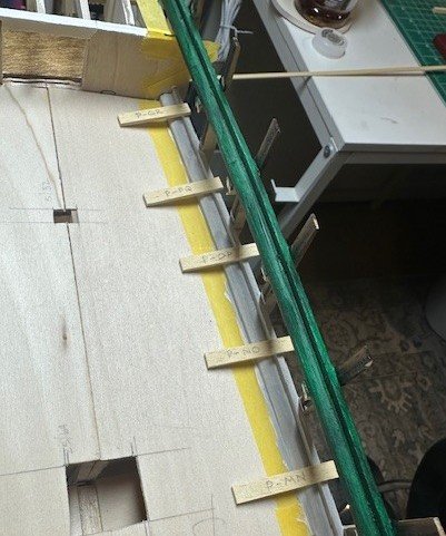
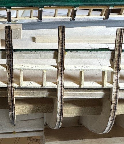
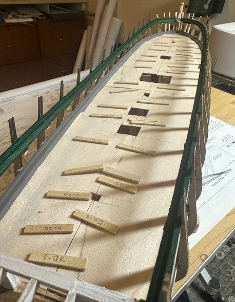
Well, I have (almost) completed the gun deck gunport framework. After my concern and query last week regarding the “fudging” of actual port locations left or right to avoid the bulwark extensions, taking both Jon’s and Peter’s notations about locations, and reviewing the old USN plans that Jon reminded me of (I had recalled seeing those somewhere before, and appreciate the reminder, Jon!), I feel comfortable where I have marked the gunport locations to be. With that said, I began measuring and cutting the individual vertical pieces of each gun port. As others have previously mentioned in their respective build logs, due to the curvature/angle of these bulwark extensions, each of these vertical frame portions needed to be cut in a parallelogram shape. While the angles changed ever so slightly on each gunport, the use of my RP Toolz Mitre Cutter assisted tremendously in knocking these out fairly uniformly, with individual sanding and shaping done for each gunport, as needed. Using the 9/16” x 13/32” square gunport spacer jig I mentioned in my earlier post, I set the spacer in the designated marked location and, with a touch of PVA glue on top and bottom, pressed the vertical frame portions against the spacer. Slid the spacer back out and… sweet! A shoutout to my Constitution predecessors for showing me that technique. And, of course, you can see in at least one of the pictures below that I placed an X in the gunport location within the frame, so I don’t mess up and forget which square is which. So, I mentioned above that I have (almost) completed the gun deck gunport framework. I still need to sand all of this framework to bring any rough or excess pieces sticking out to be smooth against the bulwark extensions for planking purposes. I’ll use a combination of my micro sander and sanding sticks, both of various grit levels. Not a big update today but, as always, appreciate the readers, follows, comments and critique.
-
Wow! That Frigate Rota figurehead came out amazingly sharp, TJM! Of course, I keep thinking, can I do something like this for the screw-elevation carronades on the spar deck of my 1:76.8 1812-ish Constitution someday?!? 🤷♂️🏆😉
-
When I first started in this hobby, I thought "Ooooh, that's a tool I need!" First time I used it, it frustrated me to no end. Tossed it in the back of my junk drawer. If you don't need the nails for aesthetic reasons, do what wmherbert suggests. If the ship you are working on really needs the nails to look right, still do what wmherbert suggests... and also do what druxey suggests, but maybe even cut the nail lengths in half so you don't have to pound in as far. Spot the points with a touch of CA glue before inserting.
-
Interestingly, K&S Metals doesn't show any 1/32" stock on their website, but Amazon (of course) is showing 2 of their 1/32" round brass rod available.
-
Thanks, Jon & Peter, for your contributions and reminders.
-
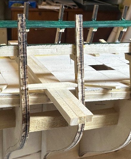
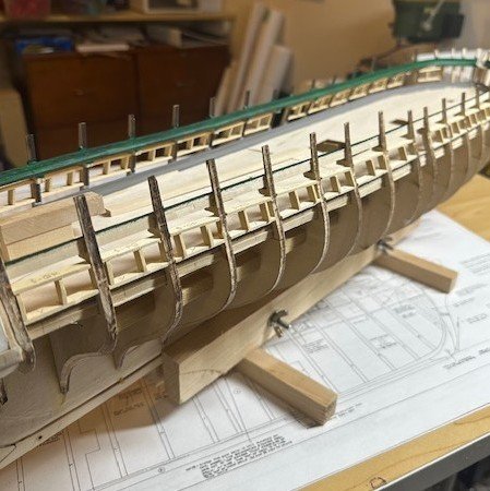
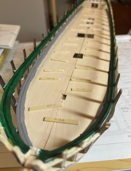
Well, let’s do a brief update on where I’m at. After completing the bottom portion of the gun deck gunport framing, I moved to the upper portion of the framing. As a guide to assist in the spacing and location of each gunport, I built a small “jig” representing the 9/16” x 13/32” square gunport space, with a base at the proper height for the gunport jig to rest while securing each upper frame. After completing both the port and starboard sides, it all came out pretty well. Yeah, a pretty basic task. When I had the full-size scale copy of the USN plan’s gundeck details printed and laid down on top of the false gun deck, I noted the locations of each gun and placed a tick mark on the outsides of the waterway at their centered locations (blue arrows in the pictures below). With a center mark drawn on my gunport spacer jig, I can then see where the vertical sides of each gunport will need to be placed. As others have previously noted, there are some of the gun locations that are very close to bulwark extensions, so that those extensions will be one of the vertical framing pieces. There are also just a couple of gun locations that are SUPER close to an extension, as depicted, for example, in this picture between Bulwark “H” and “I”. I’m curious how others using the kit’s bulwarks adjusted for this. Mustafa may have already adjusted for this in his scratch build. Would it affect the integrity to slide the cannons and carriages just a millimeter or two on the gun deck to allow for this adjustment? Recommendations? Advice? Appreciate everyone’s views, likes, comments and criticisms.


-
It's obvious to me that a few of the guys in this Constitution build log group have rubbed off on you (in a good way!).
-
All I can say, Peter, after reading all this, is... WHEW! 🏆🏆
-
And, in the FWIW category... I like your weights you are using!
-
This is WAY above my understanding of where you guys are with this rigging, but it's got me intrigued... and I love what Ken did in his explanations throughout his build... so I went searching, as well. Take a peek at his Post #672 dated July 7, 2017. There's another picture at a wider angle and explanation of him tying off running rigging to these cleats (I think!). I'll let you guys figure out if that helps in your current discussion. I'm loving your work, though, gentlemen!
-
You picked up this Model Shipways version at an awesome price, Rick! Your Amati version looks great! My Bluenose build was extremely enjoyable. Had a fun time, yet it continued to challenge me. And, yes, a ton of build logs out there to refer to, if needed. I had some favorites that I relied on, but I digress. Will watch your build log with great interest! Have fun, sir!
-
Thanks for that recommendation, Peter! I have Geoff's build log already saved as a favorite as I do for all of your other build logs, so I'll take a peek when I get closer to that point. I know I am asking WAY ahead of when I'll be to that point but... in this hobby, with this ship, I am the inquisitive type. Thanks! I know, right?!? Ken did a super job on his ship all around, and for anything involving brass, he is the king of all brass kings! He did some remarkable brass work on his own Constitution. Amazing work!
-
Looking really good, Frank! Excellent work! And thanks for the research work, since I will need this when getting to this point on my 1:76.8 scale Constitution shooting for the same "1812-ish" period. I knew there was rope instead of chain but was unclear on the other parts affecting this area. Thanks! Keep up the great work, sir!
-
Probably without too much surprise, I'm in the Concept A huddle. Whichever concept you select, Peter, it looks like you are on right track. Will be interesting to hear your continued praise and/or critique of the practicum's methods in the rigging area. Thanks!
-
Where did you get the sapele wood, Peter? I am intrigued! Why do I now want some? 🙋♂️🤣
-
USS Constitution by mtbediz - 1:76
GGibson replied to mtbediz's topic in - Build logs for subjects built 1751 - 1800
Sounds like a great two weeks, Mustafa! Enjoy your family time, sir! 👍 -
That's an innovative way to replicate planking, Peter! 👍 Well then, just don't invite some of us over to the house when it's finished! 🤣🤣🤣😉
-
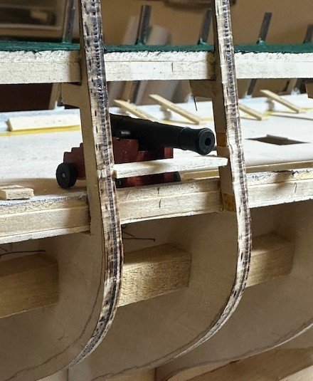
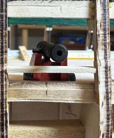
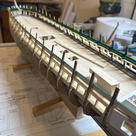
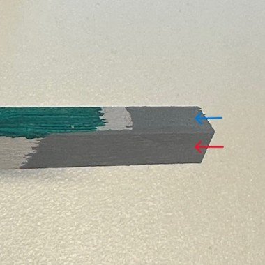
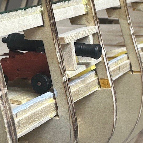
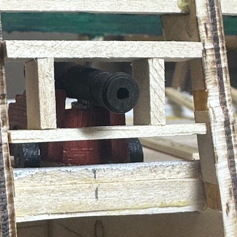
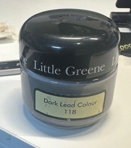
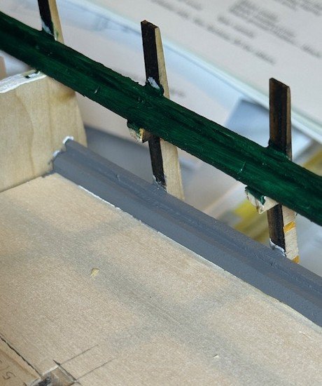
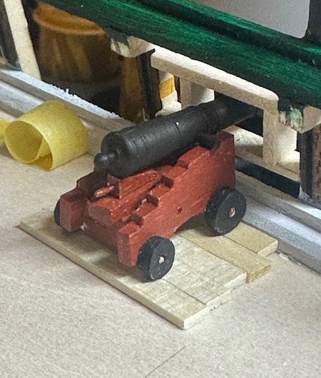
OK, a follow-up to my request for assistance in reviewing my possible gun deck cannon positioning… and a shout-out to Jon Gerson for helping to remind me of my failure to account for gun deck planking (duh!) in my initial positioning review. But first, I have been able to complete the painting of the gun deck’s waterway and planksheer. I noted in the re-listing of the USN Plan #35810, Painting Schedule that appeared in BlueJacket’s guidebook by Laurence Arnot that, while the spar deck’s waterways were to be painted green, the gundeck’s waterways were dark lead in the 1812-1815 period. Dark lead, as you can imagine, is defined as a dark grey color. While I had a small supply of Liquitex Heavy Body Acrylic Neutral Gray, I was curious about this Dark Lead color and found some (of course) on the internet. Upon receipt, I compared the two paints and, while my phone’s camera and the lighting may not do the comparison fair justice… can you see any difference?!? OK, there is a bit, but the blue arrow is the Liquitex Neutral Gray and the red arrow is the Little Greene Dark Lead. I chose the Little Greene Dark Lead for the gun deck waterways and planksheer. I don’t think I mentioned it in any previous post, but I painted the spar deck waterways and planksheer using Liquitex Basic Acrylic Green Deep Permanent paint. While I will undoubtedly do some touch-ups as I come across areas that need it, I think both deck’s waterways look good. So, now to test the gun deck cannon positioning again. In one of the starboard side locations, I built out the gunport framing. Again, the bottom frame is 5/32” above the planksheer. Each gunport frame will be 9/16” wide, and 13/32” tall from sill to header (thanks again to Jon for a nice diagram in his build log that appears to match my framing). In this test framing, I did not build the vertical framing in the parallelogram shape, but the height distance remained at the required 13/32” height. When I actually build out each gunport frame, I will use a 13/32” spacer block and the sides will be cut at proper angles, according. With that said, here’s how a carriage and cannon look sitting on the gun deck planking and with the framing. This positioning looks better than what it did previously. Any other thoughts, recommendations and additional advice?
-
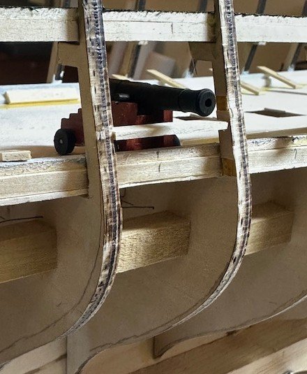
Jon, thanks for your input! And, as I was reading your response, I had an "a-ha!" moment. When taking the picture with the carriage and cannon, I placed it directly on the false deck. I need to allow for the gun deck planking, as well! Duh...!!! OK, let me make an adjustment with some planking under the cannons, I'll build out a complete gunport, and re-test the positioning. I appreciate your time in responding, Jon! Thank you, sir!
-
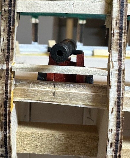
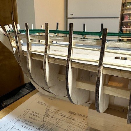
Began working on the gun deck’s gunport framing by measuring and cutting each of the bottom frames. I figured it was easier to measure them all (and marking them, accordingly) and make all the cuts rather than gluing individual bottom frames after each cut. I will now work on securing the bottom gunport frames between each bulwark extension. I do have a question, though, for those who have previously done this (I know you are listening… or at least I hope so!) I cut these bottom frame pieces using a 1/16” x 7/32” stock strip. Others have used 1/8” strips all around, I believe, in their gunport framing. However, I think others with these same waterway measurements have then had concerns with their cannon positions being too low. Here is where the 1/16” bottom frame will sit, using a 5/32” spacer between the waterway and the bottom frame. And then, pulling out the spacer and positioning a cannon and carriage, you can see the height of the cannon barrel. Assuming the 13/32” vertical spacing, it appears the cannon should end up being well centered. Agreed? I will plan on using 1/8” stock (or close to it) for the vertical sides and the top framing. What are your thoughts on using the narrower 1/16” stock for the bottom frames? Will I have issues with planking? I appreciate input on what issues I might have. It appears, though, that the cannon framing will be good. Thanks for your comments.