

GGibson
-
Posts
1,072 -
Joined
-
Last visited
Content Type
Profiles
Forums
Gallery
Events
Everything posted by GGibson
-
 Hey Peter! Looking good! I do like the gangway boards but understand that you've got to have them look right in the particular situation. I'm sure you will come up with a great solution to covering the rail end if you don't use the gangway boards.
 -
USS Constitution by mtbediz - 1:76
GGibson replied to mtbediz's topic in - Build logs for subjects built 1751 - 1800
Continued great work on your rigging, Mustafa. I, too, was having a bit of difficulty seeing exactly how your shrouds here were run and secured. Your drawing defines it perfectly. Thank you, sir! Happy New Year! -
I have this book, as well, Jon! The book shows its age, as the pages are stiff and a bit brittle, but it does have good info in it. I am looking forward to using it multiple times in my build. The terminology always causes me to pause a bit every time, too, Peter. I am slowly recognizing and understanding some of the lingo, but I am also frequently still doing an internet search on "what does this mean?!?" Wishing both you, Peter, and Jon (since I quoted him in this post, I'll include him here, as well) a Happy and Prosperous New Year. You have both been extremely helpful and supportive in my own Constitution build, and you are both extremely appreciated, gentlemen. Thank you! See y'all next year!
-
USS Constitution by mtbediz - 1:76
GGibson replied to mtbediz's topic in - Build logs for subjects built 1751 - 1800
Thank you so much, Mustafa! I wish you and your loved ones a happy and prosperous New Year, as well. Have taken a bit of a break on my build, as we were out on the beach last week and have family in this week. But next week I should be busy again in the shipyard and will be looking for more inspiration from you and the others. You are all so appreciated. Happy New Year, my friend! -
USS Constitution by mtbediz - 1:76
GGibson replied to mtbediz's topic in - Build logs for subjects built 1751 - 1800
Your rigging is really coming together nicely, Mustafa. I love your mouse construction! Another process I need to remember! -
USS Constitution by mtbediz - 1:76
GGibson replied to mtbediz's topic in - Build logs for subjects built 1751 - 1800
At first glance, Jon, it looked to me (both on the real ship and on Mustafa's) as some sort of twisted loops, rather than a simple hook. Excellent work! -
USS Constitution by mtbediz - 1:76
GGibson replied to mtbediz's topic in - Build logs for subjects built 1751 - 1800
Looks great, Mustafa! It all looks perfectly aligned. Is this the rigging I have seen referred to as a "swifter"? -
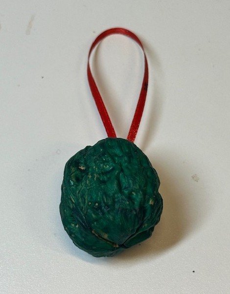
Nothing really to update on my Constitution build. Since my last post, I have been assessing where the gun deck cannons will be placed in order to prepare for the cannon framework and, as a follow-up to Mustafa's critique after my last update, determining where exactly the new spar deck beams will be placed so I can get the old beam stubs out of the way. What I have been working on, though, diligently over the past week or so is my annual Christmas tree hanging walnuts project. Back when I was a young child, my father would carefully crack open walnuts, dig the walnut and other pieces out of the shell, place money back in the shell, glue it, put a hanging bow on it and paint it so it hung on the tree on Christmas Eve. I carried on that tradition with my children and now with my grandchildren. Every year I come up with some new combination of ribbon and walnut colors in order to identify whose walnuts are whose. Most of the walnuts have some denomination of currency folded and stuffed inside them, but some just have a few pennies in them just to tease them. (Even the ones with currency in them also have a couple of dimes in them so they rattle when shaken.) Here's a picture of one of them. Each of the five grandkids have a dozen walnuts this year, so with five grandkids, that's... 60 walnuts! It's a bit of an organizational challenge as I complete them all (and keep them identified for whose are whose!), but I do enjoy it and the kids all look forward to "Papa's Walnuts"! Here's to a Happy Holiday season to all of my MSW friends!
-
USS Constitution by mtbediz - 1:76
GGibson replied to mtbediz's topic in - Build logs for subjects built 1751 - 1800
Your ship looks pretty much exactly like what I saw in Boston in September, Mustafa! Rigging is looking sharp! Can't wait to see more as your ship gets even taller! 👍🏆 -
The Testors Clear Parts Cement looks like a great solution for making faux windows! Nice idea!
-
I appreciate the feedback, Mustafa! As I was preparing for this Constitution build and researching other completed and ongoing build logs, I was trying to determine the best approach to this kit bashing and the removal of the spar deck beams in order to expose the gun deck. Obviously, in your scratch build, you were able to avoid the spar beam issues and you added the new spar beams in an orderly sequence, after the horizontal, vertical and diagonal knees were created and placed on the ship. The two “bashed kits” that I reviewed that had removed their spar deck beams fairly early in the process and subsequently added at least some version of knees were from Tom (usedtosail) and Jon, and so I’ve been trying to follow their tails as best as I can through their spar beam removal processes. As I said at the time, adding the spar deck waterways when I did added some strength and support to the bulwark extensions. One difference I have noted, though, between what Jon did, as a for-instance, and what I did is that he cut off his spar deck beams right up against the waterways. I had left mine sticking out a bit for now, subject to determining where the new beams would be located. As a part of that new “plan my approach in advance” strategy I am employing, now is the time to make those spar deck beam location determinations, so that the knees locations can also be best planned. And, to your point, Mustafa, regarding gaps in my updates, including too many steps in each update, and not allowing you veterans an opportunity to provide timely advice, I will do better in keeping future updates more concise. Again, I appreciate your input and advice, fellas! Thanks!
-
Of course, you know that I'm nowhere near this point (ha!), but I did check my inventory and have all three chain links in my kit. I'm happy to share if you need the smallest size.
-
Hi Mustafa! Thank you so much for peeking in with your advice and recommendations. I cannot adequately express how much veteran advice from gentlemen like you mean to me in this build process. We are so lucky to have you guys around. With that said, yes, my plan is to expose the gun deck similarly to what you and Jon have so successfully done. You had given me the reminder about the spar deck beam replacement concern back in October on Post #73, and I have not forgotten that reminder! When I cut those old beams, I cut them back to a point where, whether new beams are attached back directly to them or if they are just left as stumps because of new beam positioning, the old stump portions would be "hidden" under the spar deck edge decking that will be in place for the carronade guns and carriages. I am wondering now if accurate placement of the gun deck knees (directly under the spar deck) will be affected by any of these stubs. Perhaps those stubs affected will need to be cut back farther against the bulwarks. Since yours was a complete scratch build, of course, you didn't have the old beam stubs to be concerned about. I will, though, look back and see again how Jon handled all of this in his kit-bashing. In your reminder post on Post #73, you provided a build log location on Jon's log where he raised his concerns. Time to go back and study this all in greater detail and, as you stated above, Mustafa, plan my approach in advance! Once again, I appreciate ALL of you gentlemen that preceded us in these early steps!
-
Hey Terry! The Bluenose looks really nice. Very interesting color on the lower hull. I love its uniqueness! And the launch ways looks sharp, as well! I had seriously thought about a launch way for my Bluenose but then bailed and did a standard pedestal base. Now that I see yours, it's tempting to go back and do one for it! 👍🏆
-
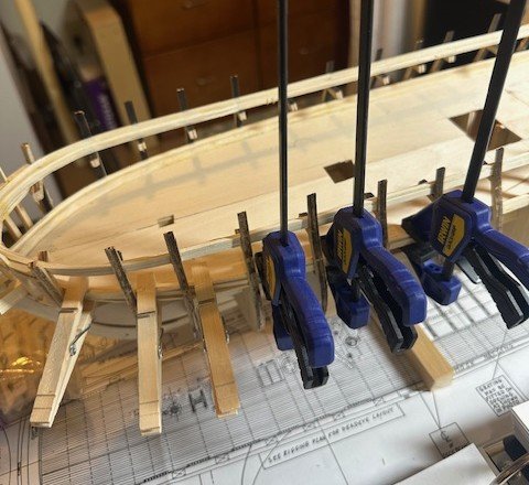
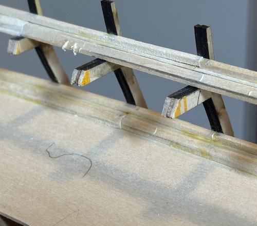
Completed a few other things, so another quick update. The gun deck waterways and planksheers placement didn’t take too long to complete. It was pretty much and “rinse & repeat” process from what I had done previously for the spar deck waterways and planksheer. For the gun deck waterways, I did not have any 5/16” x 5/32” strips handy, so that gave me an opportunity to cut a few strips on my Byrnes saw from a 5/32” sheet. I then used the same process I did on the spar deck waterways, trimming a 45-degree bevel into one side 3/32” deep using my disk sander. Longer strips were placed from the stern bulkheads up to Bulkhead F. A curved waterway piece was then measured and cut for the sharper bend from Bulkhead F up to the bow. The planksheer joint was made at Bulkhead G and, again as I did with the spar deck pieces, I was able to bend the forward planksheer strips by simply holding them under running hot water for a minute or so. All in all, no issues, especially since I had done the same process earlier for the spar deck. The closeup pictures of the waterways and planksheers also reminded me that I need to give everything a nice bit of sanding, too, before painting them! I’ve been wavering a bit on what to do next… either the gun port framing on the gun deck or the planking on the gun deck. I believe the gun port framing will be next, though. I also need to do some more work back in the Commodore’s Cabin area, which will affect the planking, as well, so… onward to lots of gun port framing! Appreciate the quick peek, comments, advice and criticism.
-
Your Pram is looking great, sir. Excellent work! And no visible blood stains from your culinary injury! I'm a big fan of Tamiya White Putty. It is advertised primarily for plastic models but can also be used for wood application. It has worked well for me.
-
Your rudder work at the stern looks awesome, Peter! Excellent! And... as we have all said at one time or another on each other's build logs... while we all strive for perfection and see the "little oops" in our own work, no one is going to be taking a magnifying glass to your work once it's completed and in the display case. The picture view you are sharing with us is what everyone will see once completed. I'm not saying don't fix what you are seeing, but... ok, nevermind... we're all going to fix our "little oops", anyways. CARRY ON, SIR! 🤷♂️🤣🏆
-
These look great, Chuck! Have you seen any 3D printing plans for the 32-pound carronades with the elevating screws? I have seen one other company that has created those, but always curious to see options.
-
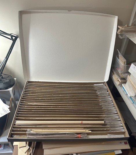
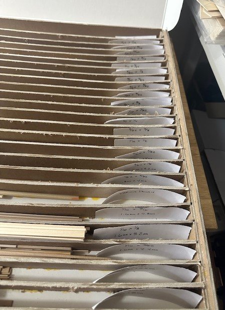
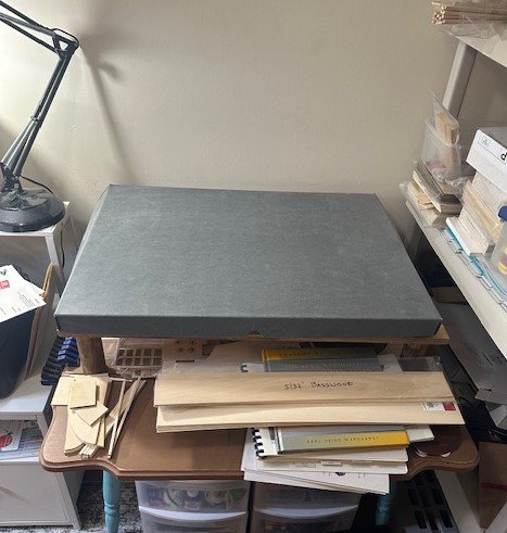
I am a bit late to the conversation, but a few years ago, I purchased from Blick Art Materials a 22" x 30" x 1-3/4" archival storage box and a few sheets of chipboard for the dividers and made a storage box for my various wood strips.
-
Peter, in a shipbuilding zoom meeting I participated in yesterday, a gentleman suggested using 3M Marine Adhesive Sealant 5200 for adhering copper plates to the hull of a model ship. It sounds like that would work well with brass to wood, perhaps, as well. Several others chimed in and said they've used it successfully, too. Perhaps worth a go?
-
Both excellent suggestions/reminders! Thank you, gentlemen! Much appreciated!
-
Well, I completed two of the three steps that I intended. My shipyard work this past month has had its share of interruptions, with a trip to Iowa for one extended weekend plus with the Thanksgiving holiday, but I did get some work done on my Constitution, albeit at my slow and deliberate pace. After making the changes in the main hatch position, I was now ready to secure the false gun deck to the bulkheads before beginning the additional work on the gun deck itself. A fairly easy and straight-forward process of gluing each of the four individual false deck pieces in place and, using some spare square dowels and longer rubber bands to hold the false deck in place while the glue dried, the false deck was secured. The pair of aft hatches that are located on either side of the capstan were the simplest to build, as there was no grating involved. Simply two sets of stairways with the ladders facing athwartship (I learned a new nautical term!). With all of these hatchways, I am using 3/32” x 1/4” basswood stock for the frames. In a previous post, I described how I built the lower ladders that go from the gun deck down to the berth deck. Since these will be difficult to see details, these stairs are simply small blocks glued together in a stairstep fashion. The lower railing stanchions are blackened 0.81mm brass rods. I used a different process this time to blacken the rods. After dipping them in white distilled vinegar to clean them, I painted them with the JAX Pewter Black product using a Q-tip cotton swab, then rinsing in clean tap water. I have been really happy with the results! For these lower “berth deck” level stanchions, I used a spot of CA glue to secure the 0.25mm rope for the rope railing. I am, of course, leaving lengths of railing rope loose at this time to eventually place the gun deck level stanchions at the appropriate time. In my last build log post, I mentioned how I was switching, or pivoting, the position of the main hatch so that the ladders were in a forward/aft direction rather than side/side direction (or athwartship, as I learned a new nautical term!). As others have previously indicated, there are several plan interpretations of how the main hatch looked. One configuration that I recall Jon mentioning is the US Navy’s 1927 restoration work Plan #24423. But… is that the way the main hatch looked back in its 1812-1815 days? The plans from Bluejacket Shipcrafters are presented based on Larry Arnot’s research during this 1812-1815 period. What the heck, let’s use that configuration. They look pretty close to one another. I had also mentioned in my last build log post that I was going to use Mustafa’s process in creating the criss-cross hatch grating work. After that comment, I found some flat pearwood grating strips on Dry-Dock Model’s website. They were advertised as being 1:72 scale, so they are close in scale to our 1:76.8 scale. Their grating slat spaces are only 1mm in size, which is closer than what I was planning on doing on the mill at 1.4mm. A 1mm opening converts at our 1:76.8 scale to just a smidge above 3 inches, which is probably a more accurate hatch grating size, anyways. So, I went with these grating strips. Using the aforementioned Bluejacket plans, I wrote up a sizing plan for my Constitution’s gun deck main hatch, which helped me keep things organized while cutting each of the grating pieces to their accurate size, along with the stairs in each corner. And, of course, I have to include a couple of my magnetic box and Lego building pictures… Although none of these hatches have been firmly secured yet to the false gun deck, I placed them all in position to see how they were going to look. First, a quick peek at how the ladders look under the false gun deck (noted with the drawn red line)… And a shot of the full false gun deck with each hatch in place… A close-up of the forward gun deck hatch… A close-up of the main mid-ship gun deck hatch… And, finally, a close-up of the aft gun deck hatch, where the capstan will be placed in between… I am happy with how the hatches (and gratings) came out on this gun deck. I’ll decide in due time whether to use these same Dry-Dock gratings on the spar deck or attempt to make my own. What I need to work on now, though, are the gun deck waterways. Oh, one more thing. Before it gets too late and I forget, I made the necessary cuts and notches in each of the mast dowels so that they fit properly and snuggly in their respective spots on the gun deck. Of course, once the spar deck is built, we want to be able to slide these masts down into their respective gun deck positions and secure them. The notches done now will assist in that endeavor. Appreciate the peek-ins, the comments, and the criticisms. Thanks for your support.


-
USS Constitution by mtbediz - 1:76
GGibson replied to mtbediz's topic in - Build logs for subjects built 1751 - 1800
Excellent work, Mustafa! Nice use of the jig. What is the distance between upper and lower deadeyes that you were achieving? -
That's the exact brand and Alizarin Crimson Hue color I used on my lower hull, with the Liquitex Basics Acrylic Mars Black as my choice for the black portion. I am not a good spray painter, and these colors brushed on really nice for me. Also, if you haven't already prepared for it, I highly recommend using Tamiya masking tape to help create the sharp lines between colors. Nice hull work on your Bluenose, Terry! Carry on, sir!
-
Have fun with this little boat, Jasennord! It was a nice ship to continue to learn skills on. Although I don't recall the exact issue now, I'd have to look back at my build log to hopefully jog my memory, but be cautious when you get to the point of trimming the transom, as I don't think the kit's measurements were exactly accurate to what you really needed to do. It looks like you have a great start on the planking! Enjoy!

