


Larry Cowden
-
Posts
137 -
Joined
-
Last visited
Content Type
Profiles
Forums
Gallery
Events
Posts posted by Larry Cowden
-
-
On 1/8/2021 at 10:53 AM, rraisley said:
By the way, I have completed the carriage model posted further above, which I believe to be a quite accurate model of the Hahn carriage, including most hardware. I can post 3-views of it in any scale, or post a 3D model in the file formats shown below:

While the STL file can be used to make a 3D model, I can tell you from experiences that it is too detailed with loops and such for a small scale printout, even for a quality resin 3D printer, which my son has. 1/48 scale /may/ work. 1/98 does not. 1/72, doubtful. Although it could be simplified by taking off the problem areas, like the loops and long, thin bolts.
Everything is drawing full size, so all drawings and models can be scaled to any size and scale.
Sorry, but I cannot supply DXF files; Fusion 360 is unable to create them, and I cannot take the time to do annotated drawings. Especially of something I'm not using.Can you export in native dwg. files for AutoCAD? I would greatly like to have your files for working with and analysis. My email is QRRanger@aol.com.
-
On 1/11/2021 at 7:07 PM, KrisWood said:
@Larry Cowden, Thank you for all your comments! The only thing I've ever done in AutoCAD is export drawings to other formats. Yes, Rhino can natively export to AutoCAD dwg format. I think you may be correct about the diagonal frames resisting the vertical action of waves. Viking ships were built to flex with waves, which is why the frames are lashed to the planks rather than nailed. I wish I was better at CAD work, regardless of the program used, because I'm really struggling to draw the parts that are not planar, like the frames.
@Jaager, I'm currently in the process of drawing all the parts I'd missed with my previous computer's Rhino trial. Once I'm done with that I'll be getting back into the wood. I am currently using basswood for my ship model and plywood for the building jig. There will be no plywood on the model itself, though I have some poplar I was thinking of using for the frame timbers and meginhufr (equivalent of a main wale on later ships). What is it about basswood that makes it unsuitable? What species of wood would you recommend instead of Basswood?
Also, I had a boxwood bush die in my yard last summer during the drought, and I'm thinking about pulling it out and cutting it into frame timbers with my dremel saw attachment. I could have swore I'd read somewhere that boxwood makes for good ship modeling wood.
I feel your pain on those parts! When I went back to college after the Navy I took Architectural, Mechanical, Civil, and straight Auto Cad. Any 3D work in those areas I did was a struggle at times. I even did a course in Maya! So please, don't apologize to me! Would you email me your files as you go? Native AutoCAD is dwg. I would love to look at them and study what you have done. I still love CAD drafting and find it a really rewarding experience when I design things for actual use. I remember starting AutoCAD courses in DOS! Then going through the various Micro Soft versions. One marine drafting company had me working in Microsoft 3.1 platform with AutoCAD still in DOS! I still have my first PC tower the VA bought me with a split hard drive. One is DOS, and the other side is Windows 98. I haven't given it up because there are valuable DOS civil engineering programs on it that did not migrate to Microsoft.
-
On 9/5/2020 at 1:39 AM, KrisWood said:
@mtaylor, I know I'll be fine once I get used to it. At this point it's starting to feel like I'm just putting off cutting new wooden parts, the more I get into the smaller and smaller details in the CAD.
@AnobiumPunctatum, A couple pages ago in this thread we discussed the pros and cons of doing the frames perpendicular to the centerline. I opted to do them perpendicular both vertically and longitudinally to make designing easier. I'm certain the diagonal frames in the original served some purpose, but this is a model and just needs to float for a little while. I'll try for complete historical accuracy on another model.
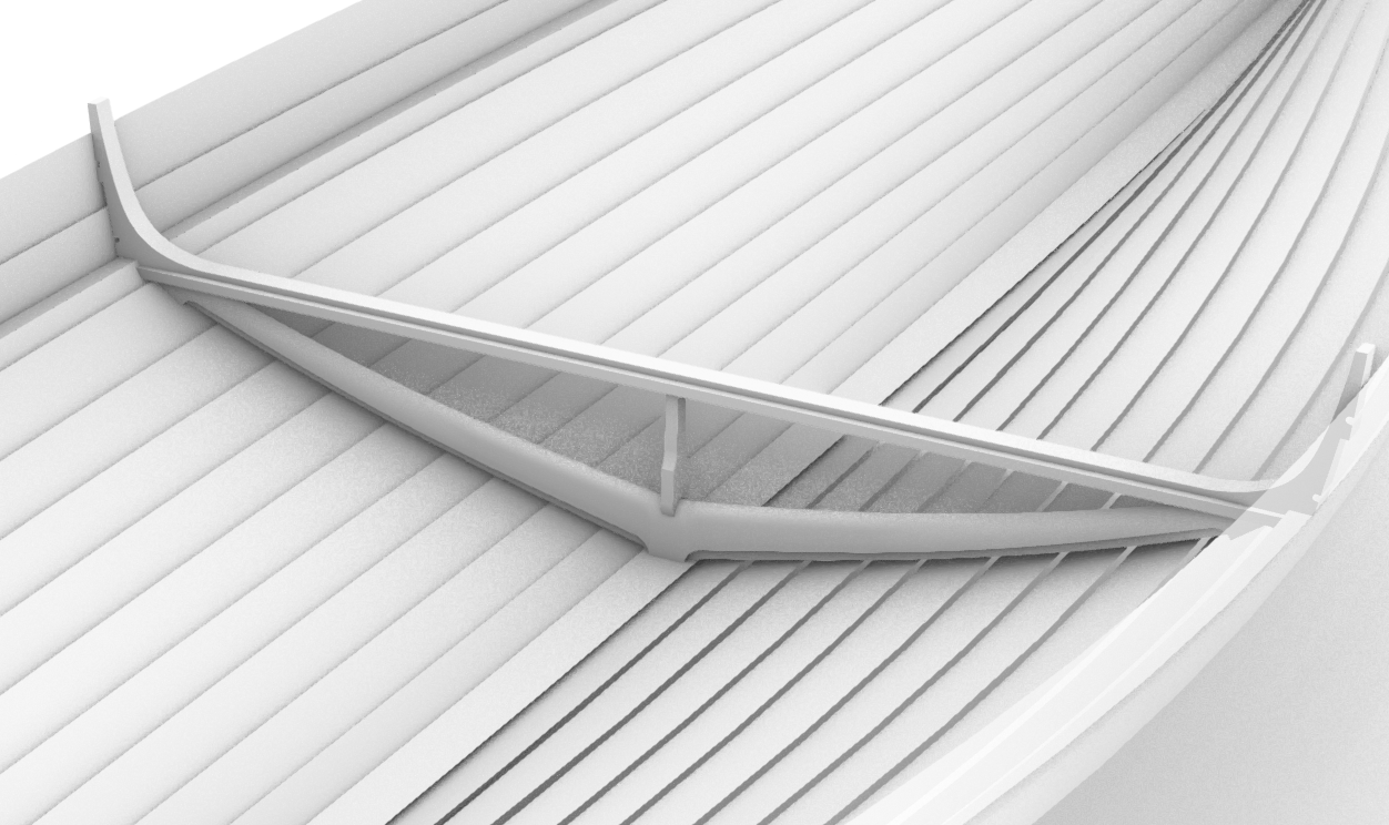
The frame I've modeled in the images above is 1A in the the Saga Oseberg plans. It's the only one I could find plans for, which I took a screenshot of from one of the video lectures by Vibeke Bischoff on the Viking Ship Museum website.
It's one frame aft of frame 0, and the mastfish covers both of them. The vertical deck beam support is only there to test out how it looks with one in place. I'll be removing it when I add the mastfish.
I haven't drawn the plank clamps yet. I'll be adding those soon. At the moment I'm still trying to find some rhyme or reason as to how tall and how wide they are. It seems to vary, even on this one frame.
I'm using Rhinoceros.
I put forth this theory. Every long ship from these boats to tankers and warships all flex to some extents vertically with respect to forces of waves acting on the bow and stern. This boat had ribs slanted for and aft. That was a deliberate design to resist deflection of the bow and stern by heavy wave actions! As the keel and hull flexed vertically with response to wave action, the slanted ribs resisted that vertical flexing. There are numerous records of modern surface ships literally breaking in half due to extreme hull stress by the vertical forces of wave actions. In fact, when we fire a modern torpedo, it does not penetrate the target hull. It explodes midship under the hull! The resulting explosion lifts the target literally out of the water and breaks the keel and hull in half. A vertical arrangement of ribs does not resist such flexing and would more easily snap the keel.
-
On 9/4/2020 at 12:55 PM, KrisWood said:
I've completed drawing one test frame! My top two strakes don't quite line up so I'll have to do some troubleshooting on those.
I will take all of your jig suggestions together and come up with a new jig over the next couple days. I'm getting so close I can smell the future sawdust from here!
I admire your skill with Rhino. I never used that one. Do those files translate well into Auto CAD?
-
On 8/28/2020 at 7:23 PM, KrisWood said:
Minor update...
I had painstakingly redrawn my top two strakes, because the planking diagram only has the starboard side and the two sides need to be proportional, and because I'm going to need to be able to eventually draw the frames to the inside of the planks, but the lines drawing for Saga Oseberg is only the PORT side. It took weeks but I finally ended up with beautifully curving, flattenable surfaces from which I could print a new planking diagram for these strakes...
Then, just as I was congratulating myself for a job well done, I realized I'd drawn them along the OUTSIDES of the planks, and because of this they no longer lined up with the lower 10 strakes. To make matters worse, I discovered that I'd inadvertently deleted the lines for the INSIDES of my planks at some point. I just about threw my laptop out the window, except that I was already outside, doing my CAD work on the porch. Weeks of work gone.

On the bright side I picked up the habit of making iterative saves periodically when I used to work as a videogame artist, so I likely have the true inner lines in one of them. I'll just have to dig through each save until I find the most recent one that still has them. Back to the grindestone...
That's a hard lesson to learn. Always back up your work. I kept multiple versions of my drawings on my computer and backed up on a separate hard drive just in case!
-
On 7/6/2020 at 2:22 PM, KrisWood said:
Ok, let's try a different way of asking the same question:
If you were building up a keel out of layers instead of as a single piece, do you think it would be easier to cut more thinner layers, or less thicker layers?
Thinner layers means smaller steps between layers and less shaping work in the filing and sanding department.
Thicker layers means less cutting out of pieces and less chance that they'll get glued on at the wrong angle, but more shaping work and a higher likelihood of sanding too much or too little.
Also related, would you shape your layers (the sanding and filing to the right thickness) before or after gluing them all together?
This feels like I'm starting all over again. I'm back to the very first problem I had, of not knowing how to work the wood in the first place. 😣
I go with sanding and shaping after laminating them together. Less chance of misalignment and breaking a piece.
-
On 7/4/2020 at 12:03 AM, KrisWood said:
Ok, what would be easier to build, the one above at 1/32" except for the middle layer which is 1/16", or the below four layers at 1/16" each?
I'll have to redraw the scarfs to accommodate the 1/16" version but that's not terribly difficult.
I say go with the 1/16"
-
On 6/8/2020 at 1:03 PM, KrisWood said:
As I'm lining up the bulkheads it occurs to me that this would be a lot easier to fair if I had some planks to line it up with. I don't want to glue it in place before fairing it if possible. The Saga Oseberg book by Thomas Finderup has a diagram of the planks drawn flat, but it doesn't have a scale. How would you go about figuring out the correct scale?
You can see the diagram in a lecture by the author in this video at 37:51
https://webtv.vikingeskibsmuseet.dk/?poditemid=40145&tagsid=121&soegeord=
The image in the book is higher resolution and I've aligned my scan of it with the version in his lecture to correct any distortion from the scanning near the binding of the book. Now I just need to figure out the size at which to cut out the planks....
I wish they had really done this in English! I'm sure there were some very interesting details to be known about building this boat!
-
On 6/16/2020 at 7:02 PM, KrisWood said:
Unrelated to the above, I'm starting to think metal rivets aren't going to be the best means of assembling this thing and I'm looking into turning toothpicks down to the right diameter. Problem is I don't have a micro-lathe. I do have multiple hand drills and rotary tools though. Does anyone have a good diy tutorials (no videos please, I'm too old to absorb information from videos) for turning a rotary tool or hand drill into a micro lathe? While I'm at it maybe I should make a micro drill press / router at the same time. I have a full size drill press but it's massive and I'd like for this rotary tool "workstation" to fit on my desk if possible.
")
Dremel makes a nice small drill press suited for this work. I have one and it works great!
-
On 5/22/2020 at 10:44 AM, KrisWood said:
Last night I attempted cutting the keel as one piece of plywood. I right away encountered many many problems with it.
- The table mounted jigsaw has a guard arm that gets in the way of cutting anything larger than the table. The keel is far longer than the table so this means it's near impossible to cut out this way. The process involved dozens of progressively larger arcing cuts, with the first few being very shallow and having to back the work piece off the blade and cutting from the other side whenever I hit the guard arm. I ended up cutting out 2/3 of it before giving up on it completely because I ran out of time for the day / couldn't cut the midship portion at all because it's impossible to cut within a few degrees of 180º.
- Once I got the aft stem cut completely cut out, it was apparent why no one builds this way, not even the kit manufacturers. The 1/4 ply was VERY flimsy. It was far lighter and more flexible than my solid basswood parts, and almost as bad as balsa. When I felt it flex I realized that every kit I've seen uses a tall bulkhead-like keel to fit the frames into. I could draw a new keel in this way but really a tat point I may as well build a kit instead of a scratchbuild.
- A few days ago, when buying the wire for my rivets, I also picked up some more wood glue. As soon as I got home I noticed that the label clearly says not to use it on parts that can get wet. DUH! It's water based glue! I've known that since I was a kid. This should have occurred to me sooner. Even if my current basswood keel didn't have terrible scarfs, it's still held together by wood glue and would come apart eventually in water. That lead me to researching marine plywood. The regular plywood I'd bought from the hardware store would delaminate if submerged for too long. I'd decided to try making a keel out of it anyway since I'm planning on burning it, but problems 1 and 2 above were too much to make it worthwhile.
I hereby speak from personal experience: A plywood keel isn't worth the time, effort, or material it takes to cut out the part!
I'm going to have to get some more printer ink so I can reprint my keel templates and make a new basswood version. At least I won't have to chisel it out this time, and I learned a lot along the way.
Edit/PS: Can anyone recommend an easy-to-use-for-beginners marine epoxy? I imagine the RC boat building folks must have something.
Go to Mudhole.com. Look up epoxies. The ProKote, ProGlu, and ProPaste Epoxy will meet your needs. I build fishing rods with them and they will certainly meet your needs.
-
On 9/24/2020 at 7:48 PM, KrisWood said:
It's the end of the road for CAD work.
I'll be losing access to Rhino soon, so here's the final CAD screenshot. Everything else will be photos of wood from here on out.
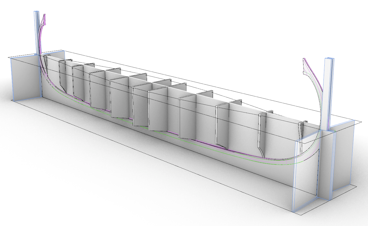
This is the completed jig design. I'm not sure if all of it is necessary, and may not end up building it this way, but it would support both the keel and the cutout. I've also made the cutout opening wider in this version than my last screenshot. The jig height is set up so that the cutout is exactly halfway up the keel and it can be flipped over with zero change in geometry.
The bulkheads will only be used in the upside down position while placing the first five strakes. After that I think the hull should be sturdy enough to flip it over and remove the bulkheads and cutout.
I've never done this before so please tell me, does this sound like a sane way to build a model?
Next step will be printing out all my parts and backing the files up to the cloud for when I'm able to get Rhino again some day.
I don't know if this can help or not. But I have had free access to all upgrades for Auto CAD for the last 16 years. I am a disabled Navy veteran. I can upgrade to all latest versions under the student/ veteran rules for free. I can't use them for commercial licensed use. But I have used many versions of Auto Cad for personal design and construction use. I designed our cabin and garage in Auto Cad in conjunction with our log home company. They were responsible for initial design and construction requirements. They sent me the dwg. files and I made the design changes on my system, then sent them back. It was the absolute great experience of my life in designing our retirement home with everything we wanted in it. I had control of all aspects of design. Electrical layout, plumbing, utilities, garage, insulation, increasing our loft, cabin size, garage size and layout, window specifications, basement wall specs. And internal layout of the cabin and garage. Check into this.
-
On 5/6/2020 at 5:07 PM, KrisWood said:
Hi @Cathead,
I don't have a table saw, so that's out of the question. I'll be working entirely with hand tools here. I do have a Dremel that could probably do the same task, but no way to mount it without making a mount from scratch, and no way to buy such a thing during quarantine.
I'd rather not glue the bulkheads to the keel as I'd just have to remove them again, and then I'd probably damage the wood / leave glue behind in the process.
I do have some heavy gauge copper wire from my metal-smithing classes back in college. I wonder if a cigarette lighter gets hot enough to anneal it and make my own rivets hmmm...
If it is within your budget, there are a number of good desk top hobby table saws much smaller than full size table saws that will give you the ability to do this.
-
On 10/30/2020 at 2:32 PM, KrisWood said:
It's been slow going these last few weeks. I've started a new job and it's taking up all my time and concentration.
I've been gradually getting parts cut out, little by little, and assembling them.
I accidentally glued the aft stem at the wrong angle, tilting too far aft. While attempting to pry it loose with a sharp knife, I accidentally snapped my keel in half. 🤣
Well, that'll teach me not to try that again.
So I reprinted my keel templates, cut them all out of wood, and lined them up with the parts I'd already cut out but hadn't glued yet.
They didn't fit! 😢
I carefully double checked all measurements and found that when I'd printed the templates on paper, the scale of each print was very slightly different, within a range of up to 2mm over the length of the ship.
Well, that's a problem. That means nothing is going to line up perfectly!
My question now is, how can I print paper templates at a consistent scale???
I'm already setting Adobe reader to print at 100% scale / actual size for my 1:25 Rhino drawings. I'd assumed that meant the resulting prints would all be at the same scale but obviously that is not so.
I'm stumped and would greatly appreciate any advice for printing consistent scales between drawings, especially for the parts that consist of multiple pages taped together when they're longer than one page.
I work in AutoCAD. I designed our cabin and garage, utilities, and everything else in CAD. Make sure your dwg file is the same as your print scale. I used Staples to print my blue prints. And I checked them with scale and they were correct.
-
17 hours ago, Louie da fly said:
Thanks for the link, Larry. However, I'm afraid much of this article is fairly shallow, and a fair bit of it is wrong. (That it uses footage from the horribly inaccurate TV show "The Vikings" is also a point against it. That really isn't what Vikings looked like and the author should know it.)
The quote from the link "Special fastening points were developed that allowed the shields to be fixed along the boat’s edges." - no problem with that part. But "This protected the crew from any projectile weapons from the shores, but also made for an efficient wind and wave break." is speculation with no real proof.
There's no evidence that the shields were used to protect against archery from the shores (though it's an interesting idea and by no means impossible - absence of evidence isn't evidence of absence).
I'd also take issue with the idea that shields would act as a wind or wave break - in my opinion they'd be quite likely to be dislodged by any sort of a decent sea. I haven't studied the pavesade (shield rack) on Viking ships in any detail, so I can't say this with any great confidence, but that's the way it seems to me. Round shields are pretty open to acting like a sail and they'd have to be tied on pretty securely not to be blown away or swept away by waves. It would be interesting to find out whether anybody's ever tried it out in heavy seas with a replica Viking ship - there are enough of them around.
I spent 20 years as a Viking period re-enactor and got heavily into the historical basis for this stuff. The Viking weapons, except perhaps the two-handed axe, were no different from those of the cultures they warred against. Their main advantages were surprise and mobility, appearing out of nowhere and attacking before a proper defence could be assembled. In set-piece battles - one army against another - against, say, the Anglo-Saxons, they lost about as often as they won.
Steven
Good analysis. But it would seem to be a regular routine when preparing for a sea voyage that the shields most certainly would be lashed down firmly to the rail. I'm a 21 year Navy veteran with service on submarines and surface ships. And on a surface ship shields like these most certainly could protect the crew from wind and waves to some extent given their otherwise open deck arrangement. I have been through many really severe storms at sea and I can tell you that if things are not lashed down properly, people and equipment suffer damages and injuries. I did 10 years historical reenacting from F&I through Fur Trade. As for weapons, that is for a different debate.
-
On 1/27/2020 at 2:12 PM, KrisWood said:
Minor updates and a question.
I'm still in the process of remaking the keel, stem, and stern parts. It's a slow going process with the tools I have available. I've decided to make all the scarfs before gluing and before shaping the cross sections of the parts this time, so that if any specific part gets ruined I only have to remake that part instead of all of them.
Meanwhile I've decided to get a scroll saw or equivalent. Currently I'm leaning toward the Rockwell Bladerunner X2 because it also includes a fence to function as a mini table saw. I know it's not the best tool for the job, but it's inexpensive and versatile and even if it's terrible it can't be any worse than my skill level with the coping saw.
Has anyone used this saw? Is it worth getting? What blades would you use for cutting basswood? Most reviews say to use Bosch jigsaw blades, but I don't know which ones to get. I already have some laying around so I'm hoping those will work, but at least they're not expensive if I need to get more.
I looked at that one on Lowe's site and I have reservations about its use on small parts. Jig saw blades create a lot of vibrations and splintering with plywood. Even the finest tooth blade will still give you fits. And you cannot cut tight curves. Look at the actual scroll saws listed. They can use very fine blades for scroll work, pretty much eliminates splintering with plywood, and won't damage your parts due to the vibrations. The cut surface is also much smoother requiring less filing or sanding.
-
On 1/14/2020 at 12:06 AM, KrisWood said:
But what if the keel isn't flat? As per the plans, it curves in all three dimensions.
Get your self some builders shims from HD or Lowe's. These are cedar or pine shims tapered to very thin surface. They should work fine for supporting your keel at both ends. Wax them to prevent glue sticking to them.
-
-
On 1/20/2020 at 6:49 PM, KrisWood said:
I'm in the process of cutting out my keel, stem, and stern parts again, and doing it by hand with a coping saw / chisels takes FOREVER and I can't get a straight line for the life od me. I tried using a rotary tool but that thing has a mind of its own and the cutting discs only like to go in a straight line.
What tools do you use for cutting out parts? Do you have any links handy for how to cut out parts that are not videos? (I learn best by reading)
I have a Shopsmith scroll saw. Works great for things like this. I recommend adding a power scroll saw to your shop.
-
On 1/7/2020 at 11:35 AM, KrisWood said:
@Cathead, I don't have a table saw, so that's out. I have a full set of X-acto blades (straight, curved, and chisel, large and small), a rotary tool that I could make into a router but building a frame for that would be a project in itself, and various files both full size and needle. The vikings cut theirs with broadaxes, so I think the closest I've got are the X-acto knives. At the moment I'm leaning toward a large file to rough it out, then needle files and sanding blocks to fine tune it. I figured out last night that I can scarf together the pieces while they're square as long as I draw the lines to cut where they'll be AFTER the pieces are beveled into wedges. If I cut the scarfs where they are on the plans at their current widths, the scarfs will end up too short after beveling.
As for the transition from T to wedge, the T of the keel transitions into a rabbet shortly before the curve of the stem and stern. The garboard strake follows the rabbet until it gets to the T, at which place it is riveted along the bottom of the T, then follows the transition to the rabbet on the other end.
You can see the cross sections before and after the transition between rabbet and T on the left hand side of the plan of the keel drawn of the original ship by Fr. Johannessen in 1933:
http://www.unimus.no/felles/bilder/web_hent_bilde.php?id=12384245&type=jpeg
Here is a photo from the construction of Saga Oseberg showing the garboard strake being fitted, where the transition is clearly visible toward the forward section of the ship in the right hand side of the photo:

For the work you have described, the best setup is a router table with a guide pin to control the shaping of the rabbit. You can control the start point and end point of the rabbit and tapering from there. Dremel has the equipment to do this.
-
On 1/2/2020 at 12:18 AM, KrisWood said:
On this attempt I used a razor saw. I've also got a coping saw but that never cuts straight in any direction. I'm thinking about using an X-acto chisel for the next attempt.
Edit: I think I figured out a way to do it. If I mark the line on both top and bottom, and then saw from the end rather than from the top, I can make sure the razor saw follows both lines. If I cut along the outside of the line on the second piece then it should be pretty easy to sand it to fit.
I highly recommend the use of a scroll saw for cutting any such work as that.
-
-
On 12/13/2019 at 12:52 PM, KrisWood said:
Oh also, I've ordered a copy of the Saga Oseberg book by the master boat builder of that ship:
https://mindzone.dk/saga-oseberg/
This should help immensely with the project. It looks like it has far better plans than anything I've got so far.
DGood idea! But who can translate it to English?
-
On 12/2/2019 at 11:16 PM, mtaylor said:
Kris,
I did a quick search of term Viking for scratch builds here on MSW. There are couple and some that might be relevant in style: https://modelshipworld.com/search/?&q=viking&type=forums_topic&page=4&nodes=11&search_and_or=and&sortby=relevancy
That link is broken and empty according to Model Ship World. Anything else?
-
On 12/2/2019 at 4:03 AM, Bob Cleek said:
Don't waste your time with balsa. It is too soft and your keel is the "backbone" of the entire model. Balsa is for model airplanes, due to its light weight. It is not suitable for ship modeling. I could go on explaining the many reasons for this, but you're just going to have to trust me on this one.
Pictures help a lot with questions like this one. It sounds like the keel is somewhat trapezoidal in cross-section, which would be expected. There are many ways to shape it. Lay out a centerline all along the length of the top and bottom of the piece. Then lay out the shape of the bottom, turn it over and lay out the shape of the top. Then shape it to the top and bottom outer lines. Of course, you will also have to lay out your rabet and carve that into the top edges of the keel. This should be shown on the plans. You should also give some thought to a building jig. These Nordic vessels, I believe, were built "planks first" on a few temporary molds and the frames and floors were installed after the planking had defined the vessel's shape. You will have to build on some sort of a jig or forms, or you will have nothing to hang your planks on.
A jig saw could shape the larger dimension, and the rest of the keel could be developed by planing the sides thereafter. Obviously, you've discovered the limitations of a razor saw, which is generally useful only for crosscutting straight stock. A coping saw or the like is required for curved cuts.
I don't want to hurt your feelings, but in the interests of honesty, it's apparent from your questions that you lack the basic tool skills and knowledge of boat building to get anywhere at the rate you are going. These longships were very sophisticated in their design and execution. The plans you have, assuming you speak the language in which they are written, are not suitable for a beginner. They are not easily built hulls. There are many longboat kits commercially available. You should use the search engine in the forum to read all the build logs of them, read all the kit reviews of them, and decide which best suits your needs and skill level. There's nothing worse than biting off more that you can chew. Start with the "baby steps" and build upon what you learn. You'll master the skills quickly enough. It's not a subject that anyone at your skill level should attempt to scratch-build. Don't feel bad about that. Just accept that the learning curve is greater than you first imagined. There's no shame in that!
Very good info. I looked at the plans on that link. Very detailed, but language is a drawback! And I suggest a scroll saw for keel, frames, and bulkheads.


HMS Victory CAD Model Research Project
in Discussion for a Ship's Deck Furniture, Guns, boats and other Fittings
Posted
Thanks will do