


Larry Cowden
-
Posts
137 -
Joined
-
Last visited
Content Type
Profiles
Forums
Gallery
Events
Posts posted by Larry Cowden
-
-
On 12/1/2019 at 1:28 AM, KrisWood said:
Hi everyone!
It's been a while since I posted in these forums, but I'm starting my first wooden ship model so I figured it was time to start a build log thread.
")
For this first project, I decided to build the Oseberg Viking longship. So far the best plans I've found are here:
http://oseberg.narod.ru/pages/Oseberg_Schiff_Spiegazioni_Pag_01.htm
If anyone knows of any other publicly accessible plans that are better, I'd love to hear about them. This appears to be from a kit model but I think that might make it easier for a first build.
I'll post pics as I make progress.
Edit: I've updated the title to reflect the plans I've settled on, which have changed multiple times since I started this thread. I'm now working from the plans by Vibeke Bischoff that were used to build the Saga Oseberg 1:1 replica, from the book, "Saga Oseberg: rekonstruktion af et vikingeskib" by Thomas Søes Finderup, master boat builder of the Saga Oseberg replica.
Many thanks for that link! It's in my files now for future build.
-
On 1/4/2021 at 3:11 PM, Balclutha75 said:
Larry, thanks for that. There are quite a few discussions here in various Viking ship build logs (binho, liteflight, Jack P, Matt H, among others come to mind, hope I have those right). Questions about if and when the shields might have been mounted. As I recall, your explanation is a good one.
Louie da Fly, a Viking expert here, has posted quite a few good links to shield information. I can easily dig those up if you have not seen them. (No pun intended on "dig those up".)
One problem with some of the kits apparently, perhaps even mine, is that as designed the kit would prohibit rowing with the shields mounted.
Here is a link for you. https://www.ancient-origins.net/history-ancient-traditions/viking-weapons-0013794 Refer to the story of the Vikings and their weapons. It also provides historical basis for shields and their location.
-
On 9/26/2020 at 7:15 PM, Louie da fly said:
To be honest, I doubt that warships were in the habit of hanging the shields on the sides unless for battle or display (and I have my doubts about battle - where would you rather have your shield - on the side of the ship or in your hand?). I think they would interfere with the efficient sailing of the ship, not to mention the likelihood of falling out of their "socket" into the sea in rough weather.
It might end up being the best solution. Use this one to get experience solving the problems, which you then apply to the new one.
A little hard to see from the photos, Matt. Do you mean that you shave the bottom of the planks thinner than at the top, so they taper down to about half the thickness at the bottom?
Oh, and no relation to James H? You have the same surname

Refer to this site https://www.ancient-origins.net/history-ancient-traditions/viking-weapons-0013794 Read the story on the Vikings and their weapons. It provides historical basis for shields on the sides of their ships.
-
-
On 9/26/2020 at 9:50 PM, Balclutha75 said:
That all sounds pretty reasonable, but they will (hopefully) look cool on a calm bookshelf. 😀
Consider this. If the Viking ship was sighted in time approaching an enemy shore, they could be subjected to volley after volley of arrows by the defenders. You can't row with your shield in your lap in front of you. If You angled your approach to shore, the shields can protect the rowers until the boat landed. So mounting the shields as shown makes sense.
-
On 6/16/2014 at 8:55 AM, wefalck said:
Many traditional fishing boats with gaff-sails and -topsails don't have them. Even when they have a square foresail (which would be lowered to the deck for furling/unfurling. It is a question of how often and how many men you would need in the mast. If the gear is small enough that one, or may be two men are sufficient to sort out gear aloft, the bosun's chair is probably a safe and fast option. It would be needed mainly if something fouled aloft in a way that gaffs or other spars and sails cannot be lowered to the deck. In this case the work is likely to be done close to the mast.
wefalck
I have some disagreement with this. A bosun's chair rigged and sending one man aloft in a severe storm or hurricane to fix a problem by himself would be suicide! That man is at the whims of a storm without any firm footing or handholds. That's a task for crew utilizing rat lines to accomplish. More so if it meant repairing rigging on spars or replacing canvas. Than footholds and handholds on spars would be necessary also.
-
On 4/1/2019 at 12:27 PM, dvlp47 said:
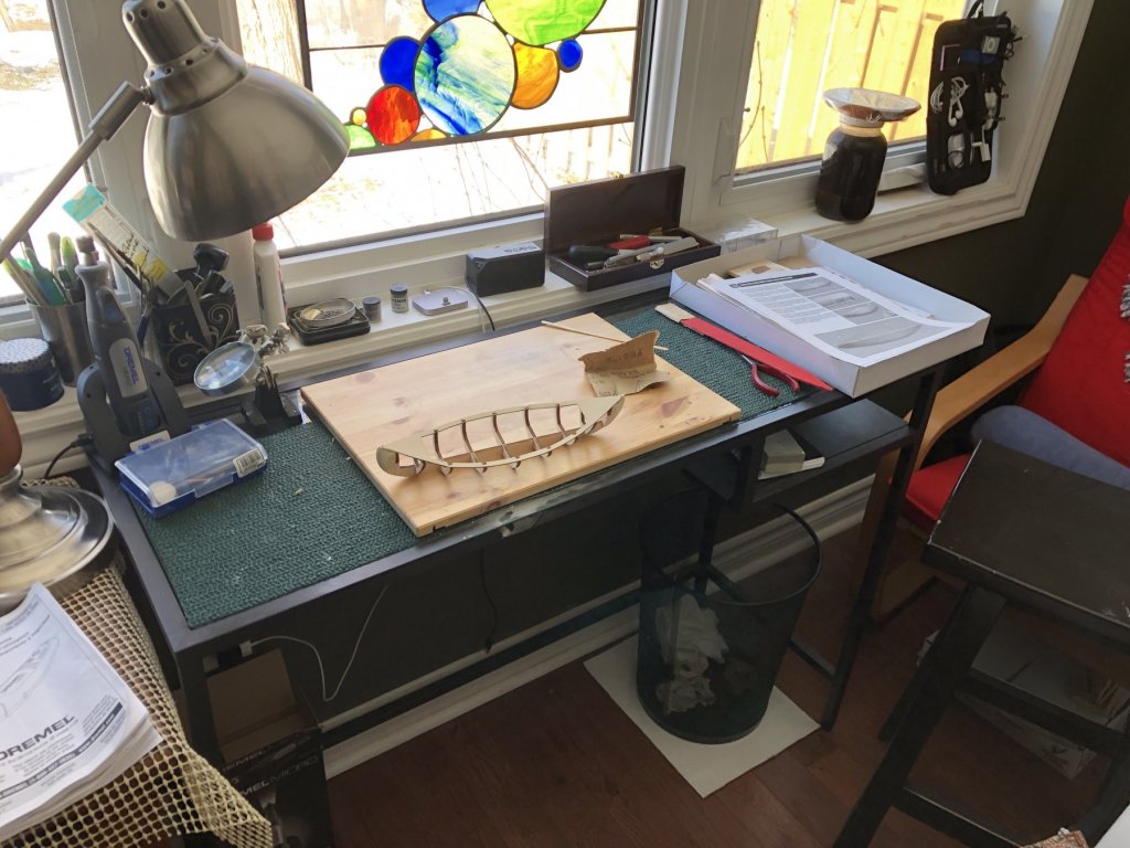
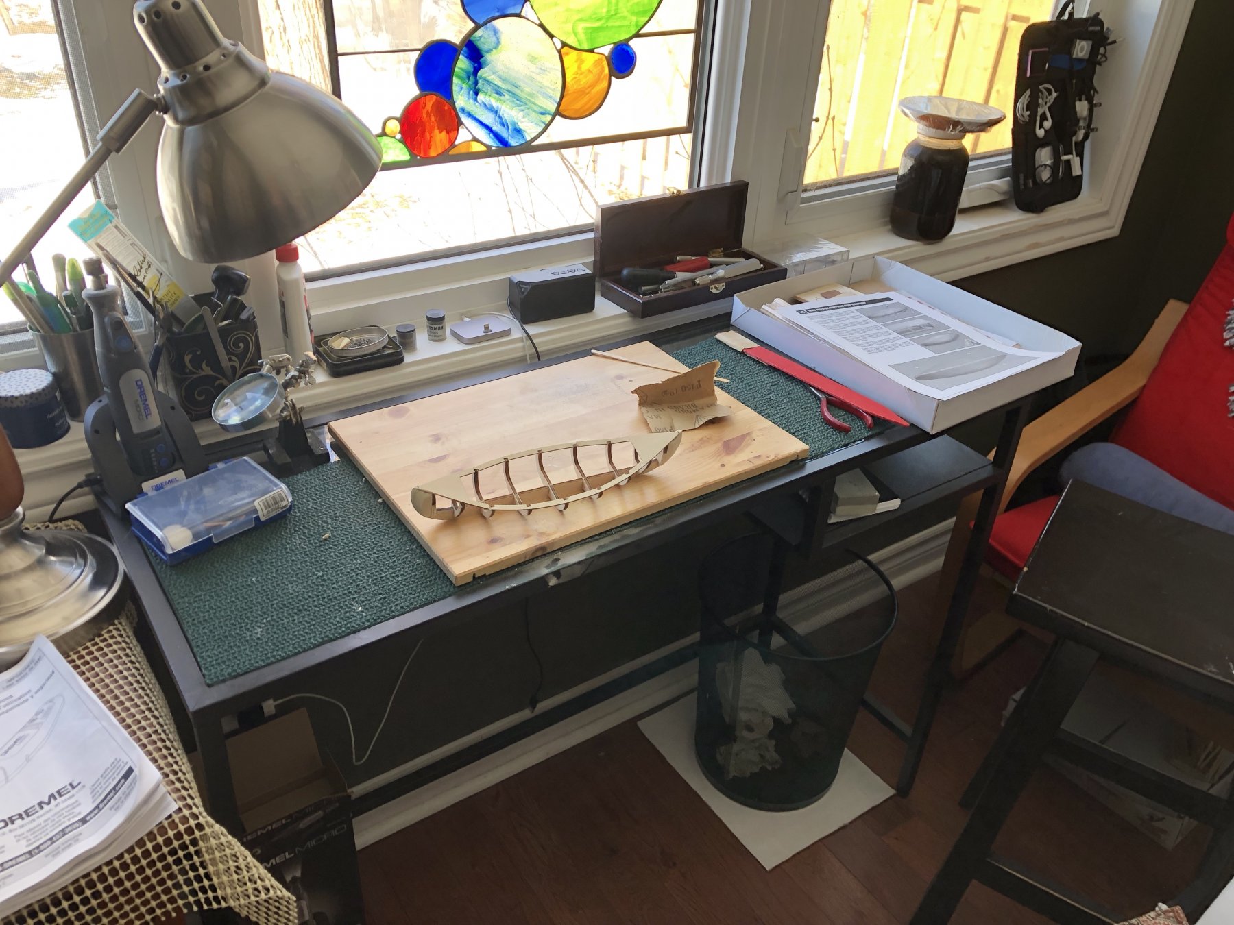
Here goes! My first shot at building. I had purchased the AL Scottish Maid and quickly realized this is by no means a beginner project, thus it has been put aside. The Viking was actually started aprox. 6 months ago and for reasons unknow it sat gathering dust. First picture is obviously the hull and my work station.
Being my first build log, my etiquette may be off please feel free to correct me
David
I have recently bought this one on eBay to build. I am certainly hoping your entry indicates you are now going forward with this build and will post pictures.
-
On 1/7/2017 at 9:17 AM, DocBlake said:
Thanks, guys.
Charlie:! I haven't thought about a name yet, only it won't be Independence". I'm open to ideas and suggestions. If I choose a real historic vessel name, I may have to deal with the nitpickers who'll point out inaccuracies in my build compared to the actual historic ship!
What would that matter? Seriously? Ships of that time were subject to frequent overhauls or revisions based on the needs at that time. Nitpickers would be seriously hard pressed to prove their claims with actual surfing documents and ship's plans!
-
On 7/25/2016 at 2:02 PM, DocBlake said:
Thanks for the input, guys!
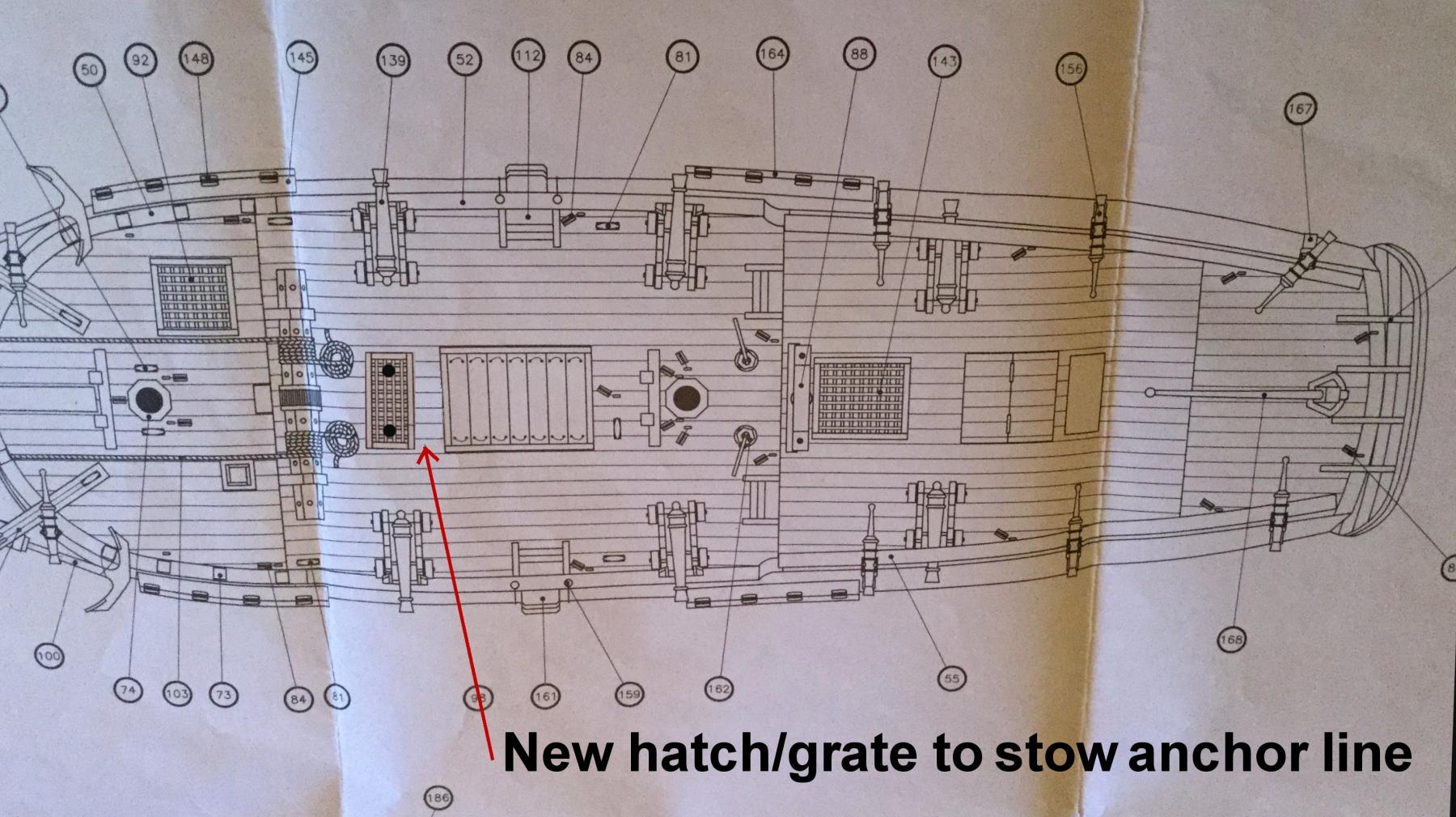
Another problem is that this ship has a windlass, but the plans show the anchor lines coiled on the deck. Hahn's Hallifax plans also show no scuttle or hatch through which the lines could be led below deck. Given the very small size of this vessel, it would seem that reducing the clutter on deck would make sense and the anchor lines would be best below, out of the way. I'm proposing adding a hatch/grate just aft of the windlass for that purpose. I think it makes sense.
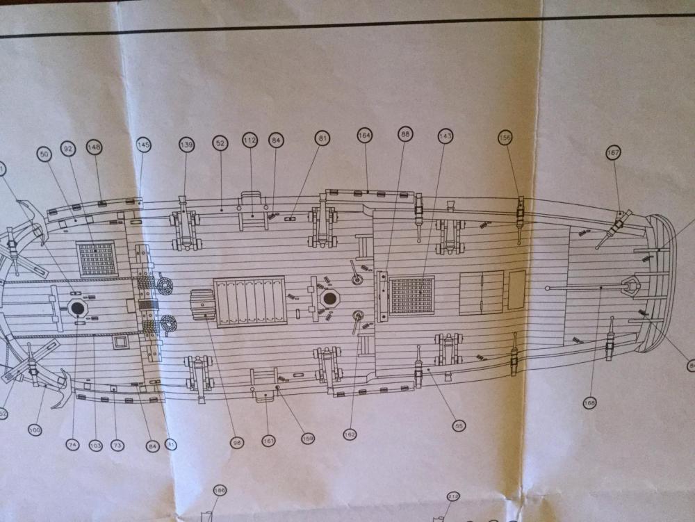
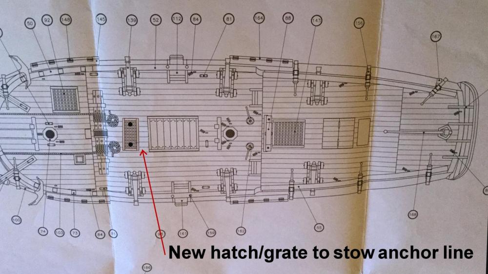
It would make sense as nearly every sailing ship and even modern ships have line lockers installed below decks for this purpose. Just because the plans didn't show one, doesn't mean it didn't have one.
-
On 7/17/2016 at 3:26 PM, DocBlake said:
Naw, Brian. This is an AL kit. The plans are more "suggestions" than actual plans! I'll have to guess on the waterline. What do you think of the color scheme (holly with stem, keel, sternpost and rudder and planking below the wale to the waterline of pear)?
You may have solved this by now. But I would place the bulkheads perpendicular to the table and mark the waterline parallel to table surface at least 15' below the main deck.
-
On 7/8/2016 at 1:17 PM, DocBlake said:
Thanks, Mike. You're making me hungry! Jaeger (Hunter's) Schnitzel - that's veal in that delicious sauce with vegetables, mushrooms bacon...yum! We have a lot of German restaurants around here - Milwaukee is VERY German. There is a place about 3 miles from our house that makes a fabulous Jaeger Schnitzel. It's called Weissgerber's Gast Haus and it's run by the 4th generation of the Weissgerber family. Sadly, it's closing this month. They're going to tear it down and replace it with...ready for this?...a PANDA EXPRESS! There is no logic or sense in this world.

Well that sucks, but Panda will never equal a great German restaurant!
-
On 5/2/2016 at 7:07 PM, DocBlake said:
The quarterdeck treenailing is complete.


Was there a reason you did not tree nail the athwartship planking?
-
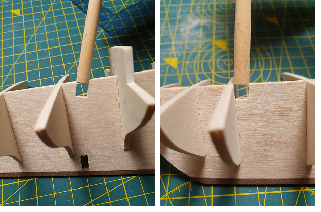
On 3/30/2016 at 7:54 PM, DocBlake said:
Hi John!
The wood is balsa so it works easily. I carved it to rough shape with a #22 X-Acto knife, and then sanded with my sanding blocks. You do have a good eye! There is a slight concave shape to the area where the wing transom would be, approaching the counter! The concavity is only right next to the sternpost on both sides. If you follow the wing transom out laterally, the shape becomes slightly convex.
I would like to know how you determined the shape to be carved for both bow and stern filler blocks!
-
On 8/6/2017 at 2:39 AM, zappto said:
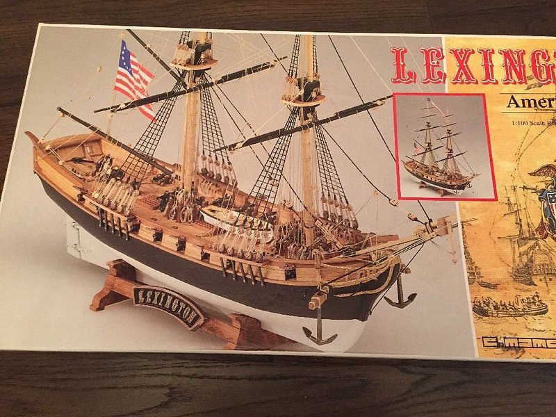
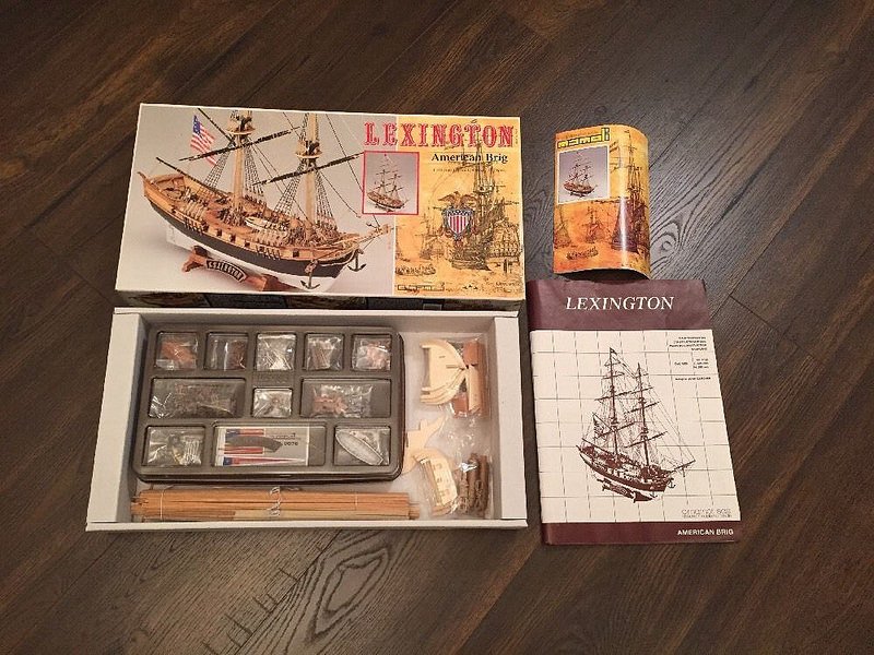
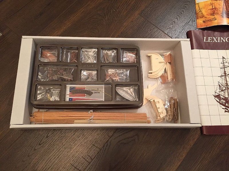
Hello, i was dreaming to build wood ship model for some time, but did not start for long time, i thought i will never finish it, as it is so delicate work. But i got for present a model kit USS Lexington. I got all the tools and started to work. Now it is 5 months of work on this model, it is taking a lot of time, it is my first model. Show you few photos.
The_Lexington 1776.
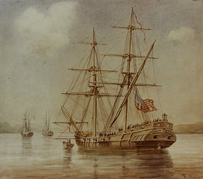
In anticipation of the war against England, the merchantman Lexington was armed and converted into a Brigantine in 1775 to become part of the continental Navy. On April 17, 1776 she captured the tender Edward, the first British ship to be taken at sea by the Colonists. The following year she fought in the Bay of Biscay, the English Channel and the Irish Coast. On September 20, 1777 during her return trip from France, the Lexington was overtaken by the English cutter Alert. After a fierce gunbattle, Lexington ran out of ammunition and was forced to surrender.
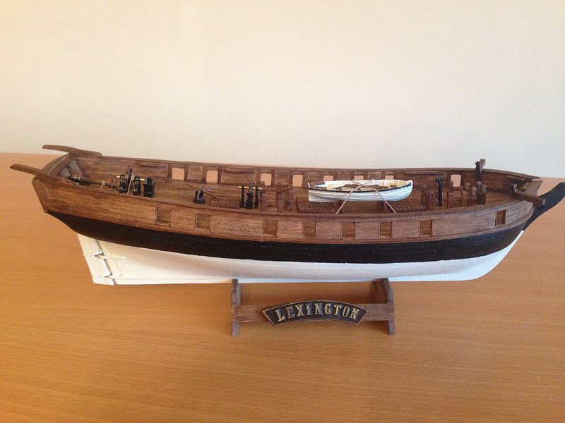
To make nice gun holes not an easy task!
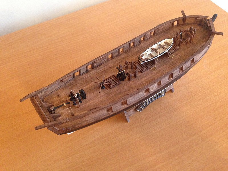
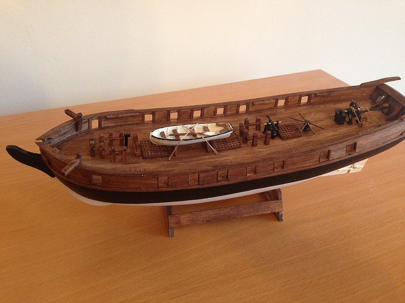
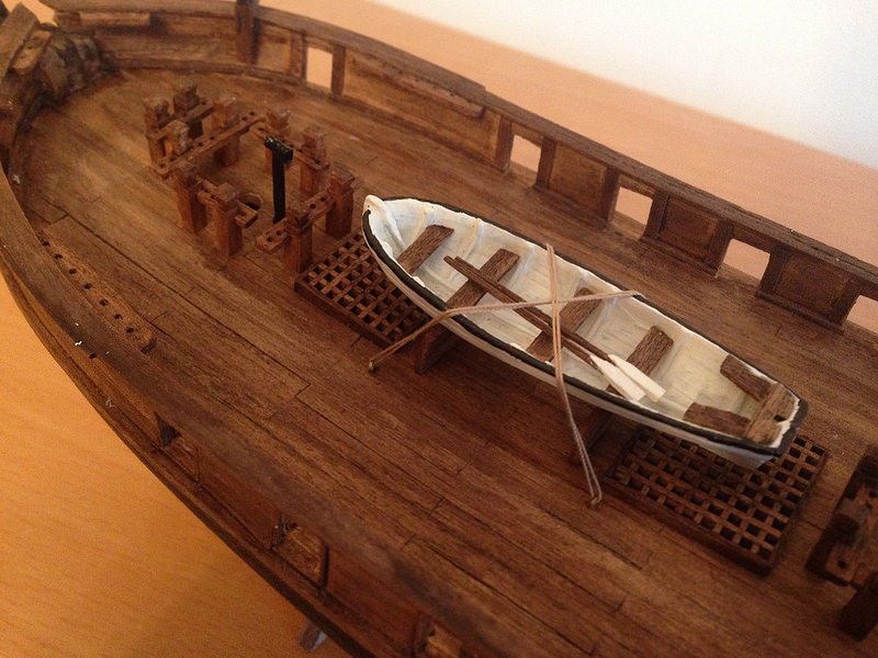
Life boat is painted.
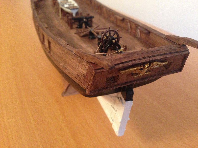
Steering wheel is working.
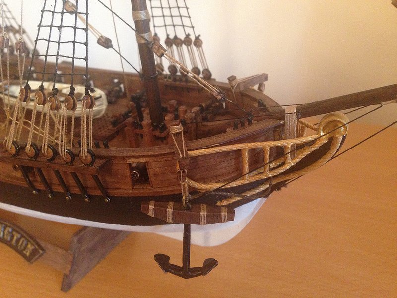
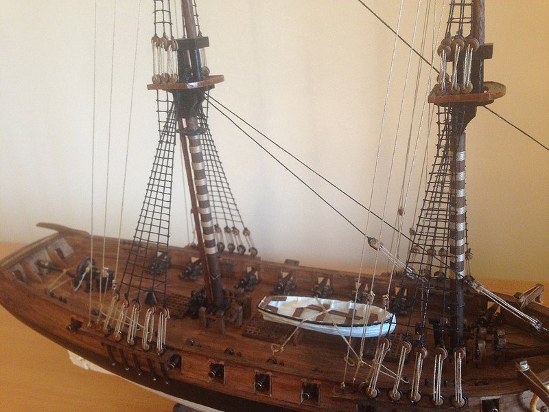
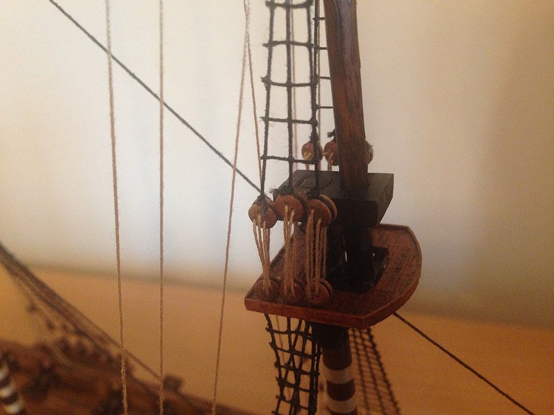
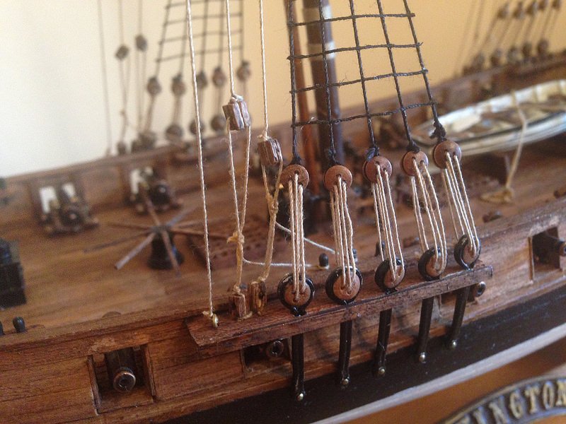
Work is on progress, now rigging the ship.
Hi Zappato,
I have this kit on my shelf awaiting building. As you are well into this build, can you give me a list of problems you may gave encountered with the kit? Material deficiencies? Instructions? Drawing errors? Quality of parts? I always like to research models in progress by builders before jumping in. Always an amazing amount of information I am getting from them. Even enough to steer clear of a certain maker or scale. Thanks!
-
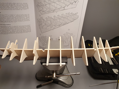
On 11/25/2020 at 7:16 PM, Colin_C said:
Well, I've made a start.
My first problem of identifying lath 13 was solved. The instructions describe this piece as being 3x3mm, and my only decision was which piece to use. I have 2 identical laths of these dimensions, just a slight difference in colour. Throughout the instructions there is only reference to "walnut" and "lime", so I took a punt and used the slightly darker one, "a bit more walnutty than the other walnut one".
 "
"
Since then I've mostly been sanding and filing. All the slots in the keel and frames needed widening to allow them to fit together. I also had to make the slots deeper to the top of the frames would sit true with the keel (instructions did note this would be required). And I evened out the camber on some of the frames as they were clearly not symmetrical.
A lesson learned here was that my filing "style" must have been at a bit of an angle, because I wasn't filing evenly. This meant a couple of the frames didn't sit naturally square on the keel. There was enough wiggle to make them sit square, but I was concerned about twisting the keel a little by forcing it. So I tidied these up to get them to sit better.
Frames 8 and 10 stick through the deck, but these were too both too wide and needed filed down to make them fit.
Next, the holes in the deck and slots in the keel for the masts are too small and needed opening up a bit.
So far, much the same as @Cathead's experience. There's a little fine tuning to do, but it looks like the frames all fit well and the deck will sit okay on top of them. When I glue them in I'll make sure they are all perfectly square.
Now, this is where it gets interesting. Maybe.
I found this YouTube video (seems top be part 1 of three). An Italian friend has kindly translated if for me and I've attached the translation at the end of this post. If it's useful, I'll ask her to translate the other two.
About 2:40 in he starts creating a rabbet. First off, when I lay my keel over the plans, nothing lines up properly. I'm guessing this is something to do with the 1:50 / 1:64 scale discrepancy, but it makes the plans a bit useless as a template. Also, this looks like something that could go horribly wrong for a man of my limited experience, and I notice that @Cathead, @mattsayers148, and @Woodmiester12 didn't do it in their builds. @trippwj had got got passed this before starting his log. The instructions don't suggest doing it. So I think I'll give that bit a miss.
At 5:57 he cuts the deck in half to make it easier to fit the curvature of the frames. I can see sense in that (and the risks), but am wondering is it really worth doing? Again, it's not in the instructions and I don't think anyone else here did it that way. Any thoughts would be appreciated.
I'll glue the bulkhead frames in over the next couple of days. My first bit of serious action. Should I do them all in one sitting, or one at a time? I was planning to use lego bricks to ensure they were perfectly square, but only doing them one at a time will really allow for that. And PVA or superglue?
Cheers
Colin
I will recommend one at a time as this is your first. This is one one of the key critical keystone blocks to ensure a correctly aligned frame upon which to build!
-
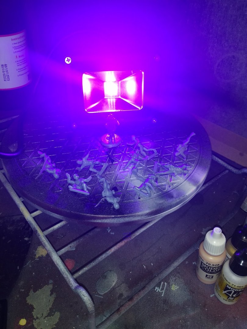
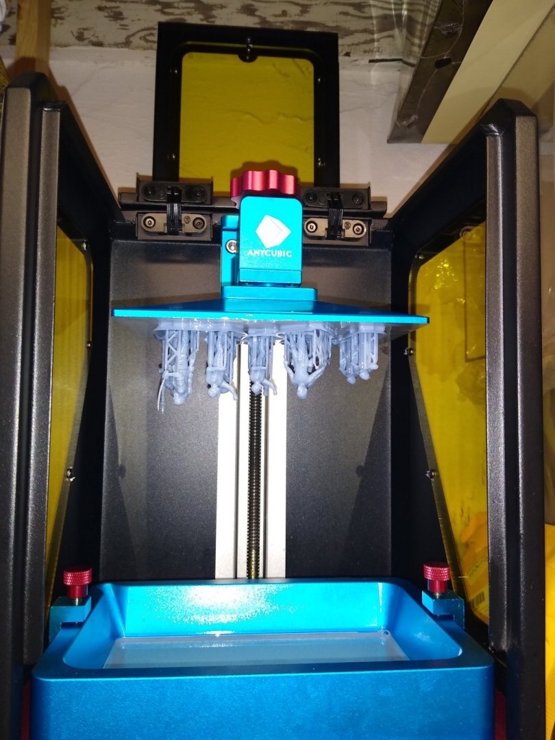
On 5/24/2020 at 11:54 PM, highlanderburial said:
Greetings all,
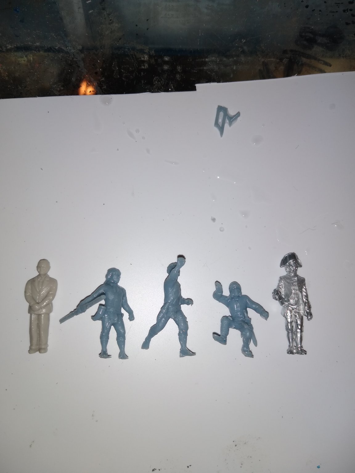
While I am pretty sure posting anything made from a 3d printer is probably bad form here I wanted to share a side project I worked on over the weekend. I personally love seeing crew figures on model boat/ships but always have a hard time finding them in the scales or poses I want. This weekend I digitally drew out 4 "age of sail" style crew in 4 poses in my 3d aoftware. I then printed them in 1/48 ish scale. The awesome part about having these designs is I can size them up to 40mm or down to 3mm tall. I think they would look at home on a pirate ship or navy vessel depending on how they get painted. In the second photo I have compared my prints to an Amati figure (right) and a 1/48 scale figure on the left. The figure with the saber was literally transposed from a Captain Morgan rum ad! The UV light is used to cure the resin.
Has anyone else done this?

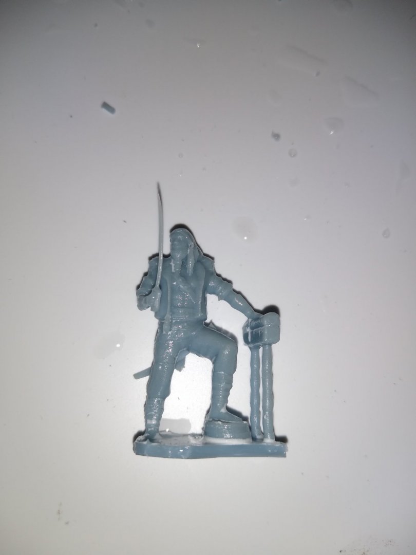
Impressive technique! I love it!
-
Who is Y.T.? And how do I find him? I am hearing good things and references to him. But every search on this site is a zero!
-
On 8/2/2020 at 12:00 AM, rkwz said:
I am in the middle of rigging the AIRFIX HMS Victory, referencing Noel Hackney's manual. One of the steps requires crowsfeet to be rigged for all 3 masts, but I couldn't find any reference to this in Longridge's The Anatomy of Nelson's Ships...
Can anyone provide any suggestions whether I should go ahead and rig them or leave it as is? (Ideally would like my model to be a representation of its condition during the Battle of Trafalgar minus any damage 😁)
Cheers,
Look up the National Maritime Museum in England. The have valuable resources on The Royal Navy and other ships. And you should find links and pictures of her as she exists today.
-
On 1/10/2020 at 11:42 AM, Emmet said:
The drills are new and came with the pin vise drill by Werkzeug.They are not wobbling very much-barely perceptible. And the bits are drilling without a problem. Yes it is a Dremel, my second. Bulkheads are plywood which surprises me because normal plywood is softer rom the side. Even when I drill a pilot hole the push pins do not want to go in. I did not hammer them but ci could give that a try. I will be resuming planking soon. Further efforts should prove worthwhile. And yes the Dremel is at the lowest rpms. When I say a little wobble I could be wrong. It may be none. I am poking a small dent so that the bit will be guided. Bare in mind the bits are only protruding about 8mm from the "chuck". Thanks for the help and input. Let's see how it goes.
A trick I use on brad pins is center punching the starting hole first before drilling. I have also lubricated the pins and nails with wax or soap to make them slide easier into a really hard wood.
-
On 1/9/2020 at 7:58 AM, Emmet said:
Here are pics of Colunbus' ships. I think you can tell from the pics above that my ship is certainly not the NIna. And my ship does not have the large foredeck of the Santa Maria. Let me know what you think. The odd part is as I said above is I ordered the La Pinta.
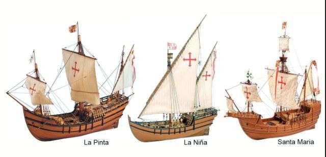
Many years ago the actual sailing replicas of all three docked in New London, CT. I boarded all three at that time. Your model is the Nina. The bow rake on the Nina I was on did not exceed the height of the quarterdeck! The Pinta most certainly dd! All three returned to Spain where they have remained docked for the public.
-
On 1/9/2020 at 6:04 AM, Emmet said:
This is Emmet. Upon doing some research I found out that the ship is La Pinta. I had ordered Pinta but the box I got said Nina. I thought I would build it anyway. I was looking at pictures of all 3 ships and it confirms that this is really La Pinta. I have to figure out how to change the title.
You have the Nina, not the Pinta..Your hull structure matches the Nina. I recommend you check Igor's build page where he is building both and have them physically lined up side by side with hull framing done.
-
Very nice build. However the changing colors of your ship are quite confusing. It appears your changing light source is affecting the actual coloring of the ship from photo to photo. What stains are you actually using? I am seeing dark walnut, mahogany, weathered grey. And what did you use on the Nina? Looking forward to a reply.
-
On 12/19/2020 at 10:00 AM, Emmet said:
Thanks for looking in. This is a stage where you must be patient and work are small details in total acceptance of how things are less than perfect.
I have wondered why you chose not to wet the planks and dry them to shape with a plank bender and iron? I have seen this used on many other builds making the mounting of the planks much easier.
-
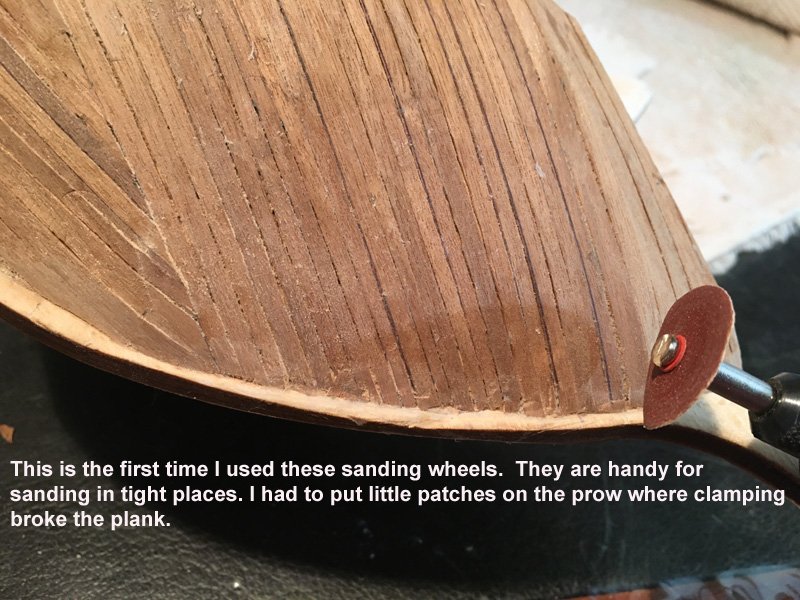
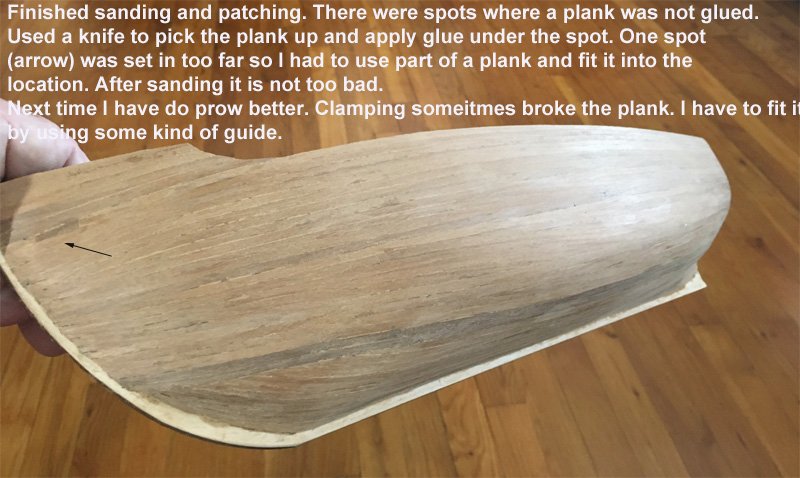
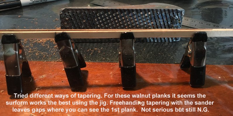
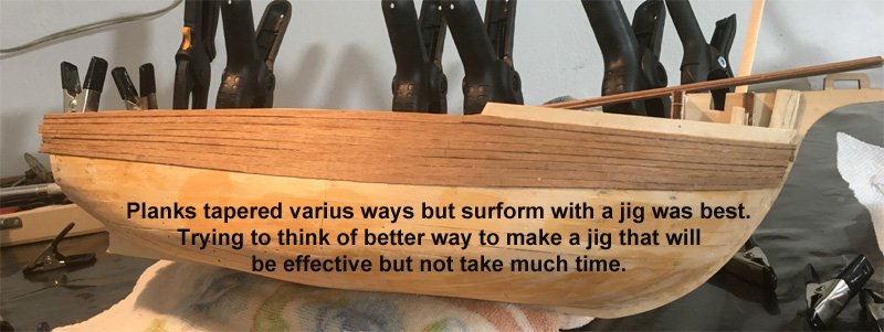
On 12/2/2020 at 8:54 AM, Emmet said:
Thanks Keith of Clearway. And thanks for the tip on the surform. It works well for these walnut planks. I had that tool buried amongst my
tools for everything you can think of box. I ordered a new blade. Interesting how a tool like that is the same for, perhaps, 30 or 40 years and you can still get a part for it.
I am also wondering now if the plank arrangement for the 1st hull was a good idea. It was easier but I need to apply the 2nd layer over it before I am sure. I still like the way Lapinas did his Santa Maria. I should add that heating the glue makes it cure faster and I am hoping that will help when I get to the area of the hull where clamping is a problem.
Have you considered a very small hobby or block plane?


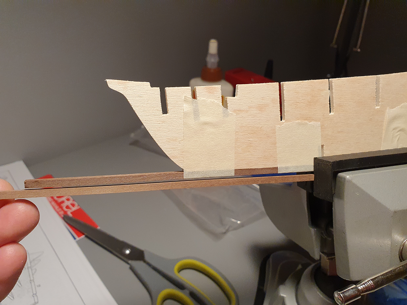
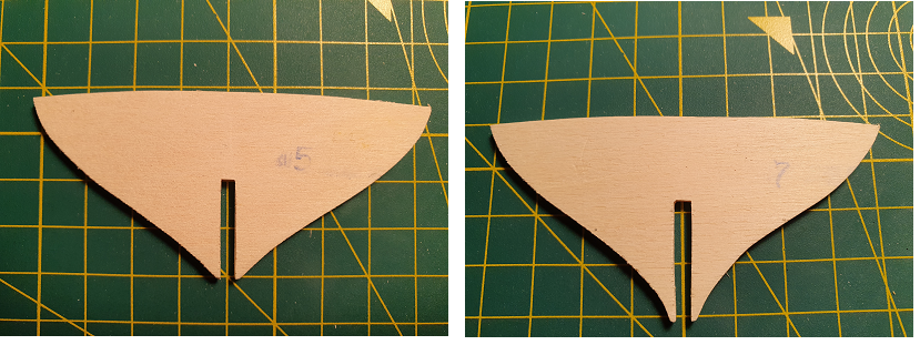
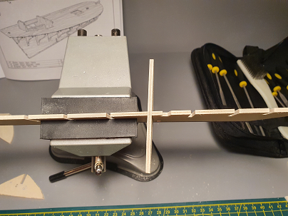
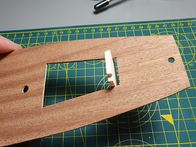
Oseberg Ship by KrisWood - 1:25 - Vibeke Bischoff Plans
in - Subjects built Up to and including 1500 AD
Posted
Modeler's Central may have what you need and many free references on all aspects of ship building! I'm still exploring them myself.