


Larry Cowden
-
Posts
137 -
Joined
-
Last visited
Content Type
Profiles
Forums
Gallery
Events
Posts posted by Larry Cowden
-
-
17 hours ago, Bob Cleek said:
Mechanical fastenings such as treenails and nails permit each plank to shrink and swell independently of the others, thereby spreading the wood movement proportionally over the entire structure, piece by piece, so long as the plank seams are not glued one to the other. When the seams are glued, the shrinkage (and swelling) of the solid glued piece will occur at the weakest point, often resulting in a split piece of wood or a cracked seam the width of the movement. Remember the percentage of movement, whatever it may be, is across the moving dimension of the piece. The larger the piece, the greater the movement across the moving dimension. If you glue a bunch pieces together, they will move as one. Instead of tiny bits of movement between each piece, you'll get the total movement of the glued pieces at one spot.
Flexible adhesives certainly mitigate the problem of wood movement to the extent they flex, but flexible joints may pose other structural problems in a model. The problem with any adhesive, including the epoxies, the limitations of their archival and working qualities. These involve the degree of long-term changes in coloration, brittleness, acidic outgassing, loss of strength, particularly shear strength, and the reversibility of the bond in the event future conservation or restoration work may be required. These considerations usually vary greatly, depending upon the formulation of the particular adhesive. At present, the "gold standard" museum conservation epoxy adhesive is a product known as HXTAL NYL-1 designed specifically for the repair of glass and ceramic artifacts. It closely mimics the refractive index of glass and so produces an invisible repair. It's claimed to be the only epoxy adhesive which does not yellow upon exposure to light. This is a very specialized (and expensive) epoxy adhesive having very exacting mixing and application requirements and, importantly, is not easily reversible, as far as i know. While it is an excellent product for glass and ceramic repair, it isn't very suitable for modeling because it has a very long minimum setting times in excess of three days! See: https://www.hxtal.com/ and http://www.lakesidepottery.com/HTML Text/Tips/Hxtal-NYL-instructions-glass-epoxy.htm
Do you tree nail or pin your planking as a standard rule for building?
-
-
On 12/17/2020 at 10:39 AM, gieb8688 said:
Hello,
If I have a ship's boat that is 9cm long, what would be an appropriate length for oars?
Thanks,
Mark
What is your opinion of the Sergal kit? I was following another builder doing a Mantua Victory and found the beam dimensions of the bulkheads were a full 1" narrower than the original plans.
-
On 8/27/2020 at 9:09 AM, jazzyrjw@gmail.com said:
Jazzyrjw
Billing Nordkap
Panart Mantua High Spec HMS Victory 1:78
Early on I noticed that you only had the slot for the main mast in the main keel. The other two masts needed a slot depth horizontally and virtically in line with the main mast. It would be very difficult to get the angles entirely right after the decks were completed. I think you are doing a fantastic job. I have read all your posts and am staggered how much you have achieved so far. I am leaving all the canons brass but painting vermilion on the centre front of the barrel. I will be coppering the hull like you so I am looking forward to doing it later. Currently, I am adding LED lighting to the officers cabins and later, up top of the main mast.
I will be painting the finished ship with the historic restoration teams new colour scheme that was uncovered during gargantuan project of restoring the ship at Portsmouth. I went to see it and was amazed by the inticate paint work done. They have changed the ships colours to reflect the true colours found in the lowest paint levels carbon dated to the battle of Trafalgar Have a look at these pictures taken by the photographer commissioned by the Restoration Team. https://www.flickr.com/photos/150573193@N04/page7
Thanks for that Flicker link! Very impressive photos for reference!
-
On 11/28/2017 at 5:45 PM, ca.shipwright said:
11/28/2017
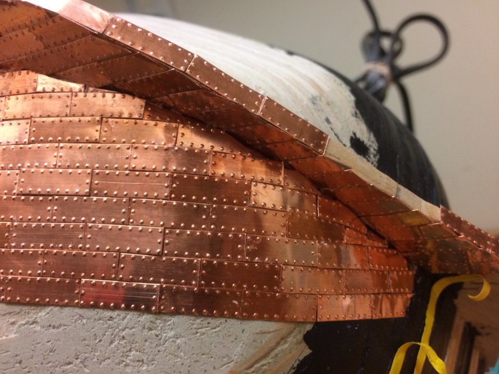
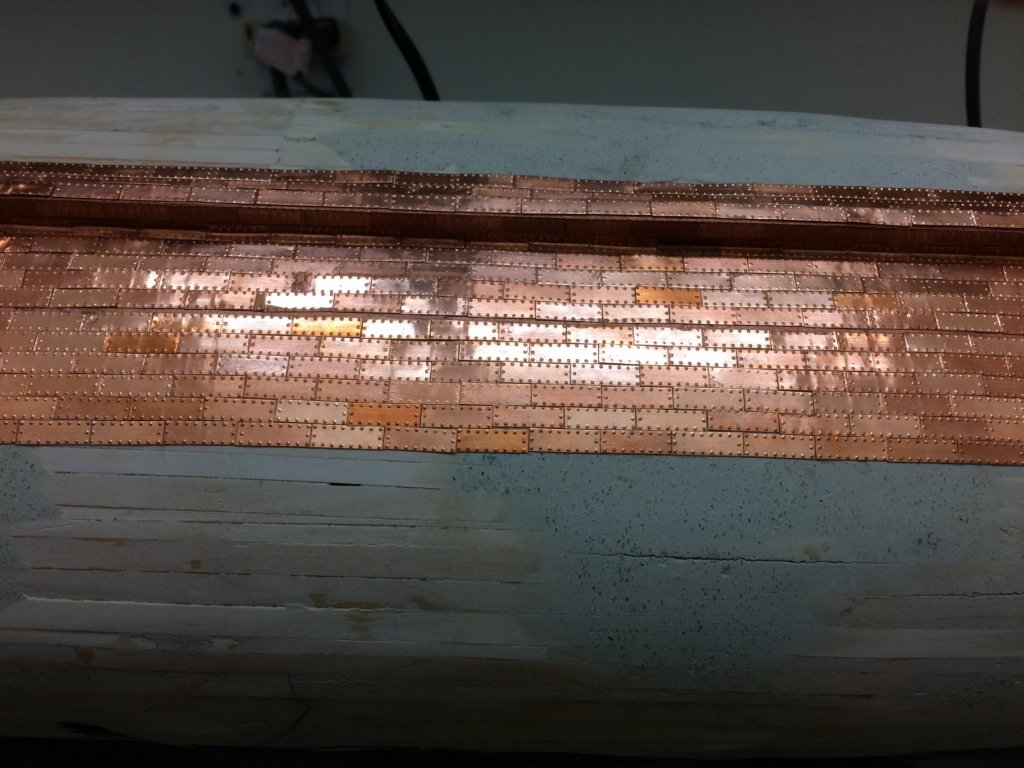
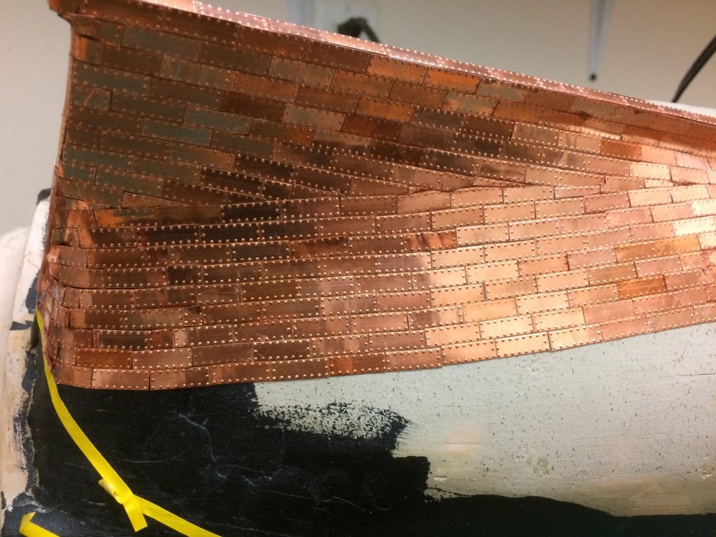
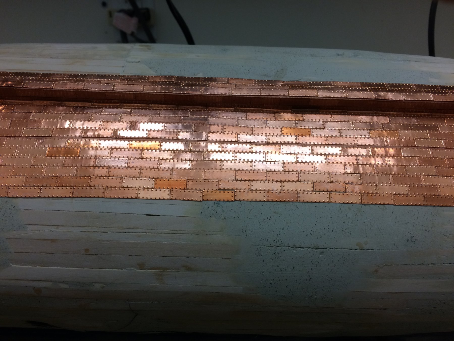
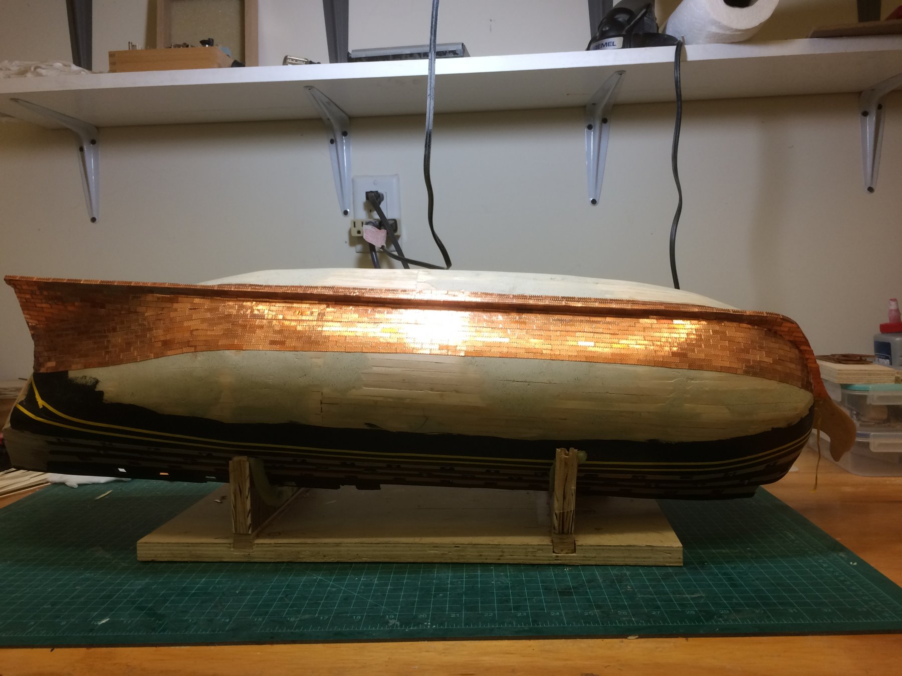
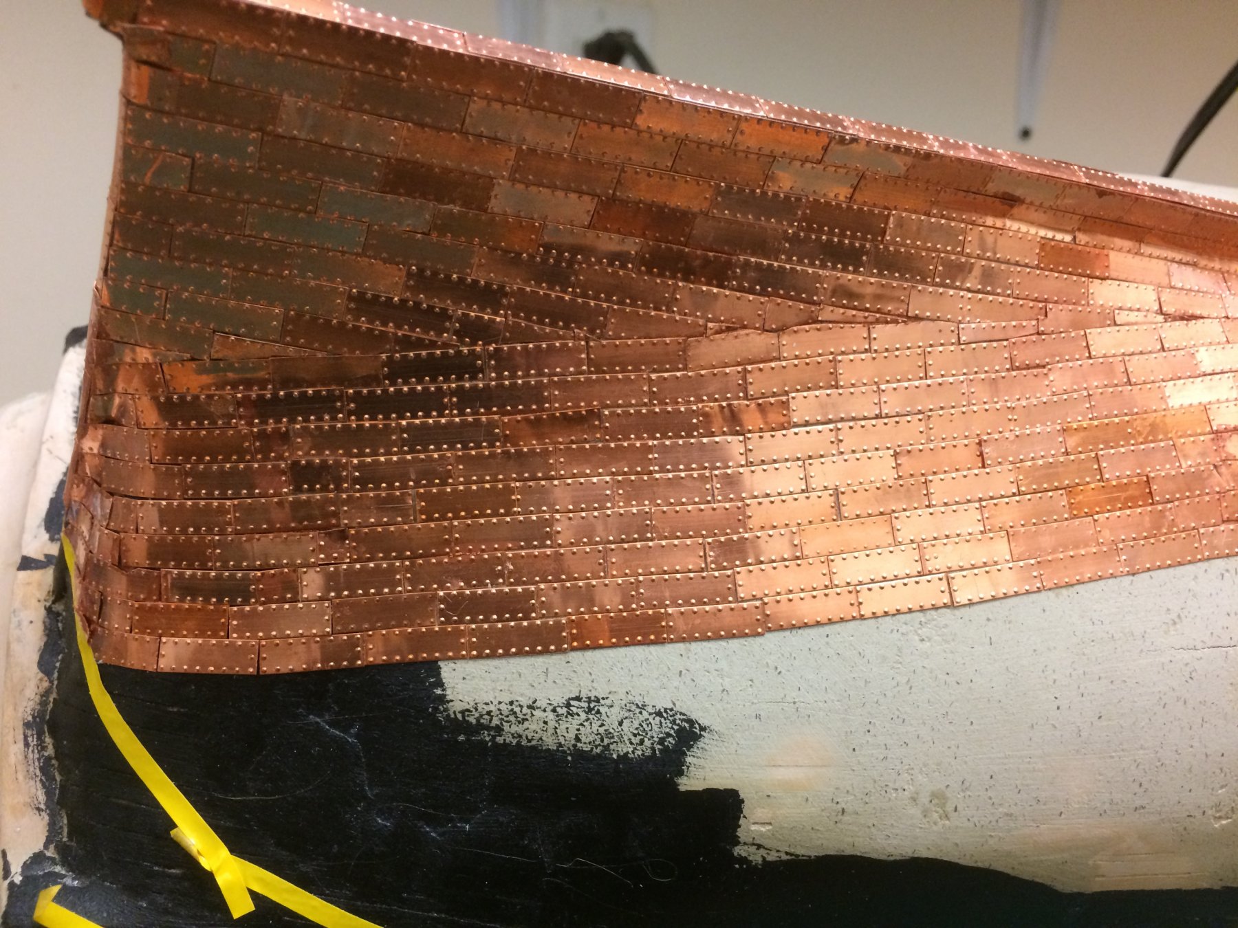
Just a short update on the coppering. This task is definitely the never ending story. I try to get three rows of the plates installed each time I work on the ship. The constant squeezing of the tweezers in one hand and the glue bottle in the other leads to some serious hand aching – like a repetitive motion injury. Three rows is just about all I can handle at one time.
I try to break the work session into several tasks. Planking the upper gun deck is one of the these tasks. Making the hatch comings another. I also mill the wood that I will need in future chapters. Holly for deck planking and Swiss pear fir the hatch comings.
I am using Temaya metallic copper paint to fill in some of the gaps where the plates don't align well. Not a real good fix, but, better than seeing the raw hull, light or black, showing through.
Here are some photos of the coppering.

Couldn You have ordered more copper from Mantua?
-
On 5/25/2017 at 2:57 PM, ca.shipwright said:Finally, the port side gun ports have all been installed, sanded and filled where needed. All that's left to do is the final sanding and adding the red and black color to the appropriate ports.I am going to wait for the color until after the starboard gun ports are at the same place. Maybe I will only have to do the color one time this way. Ever the optomist .Now for some decisions regarding the dummy cannon:Should I blacken them or leave them brass?Should I mount them before I close up the lower hull? I want to use epoxy for this.Looking at the top view of the cannon, note they sit a little proud of the hull. I get this affect by not seating the mounting pin all the way to the rear. I actually like this look.I know, my ship, my rules. But, some input would be appreciated. Might save me from making a mistake that will show further down the road.Regards to all
I'm will try to re-post photos 7222--7227 as well as the current group.

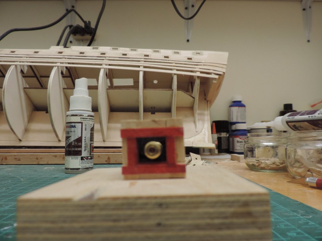

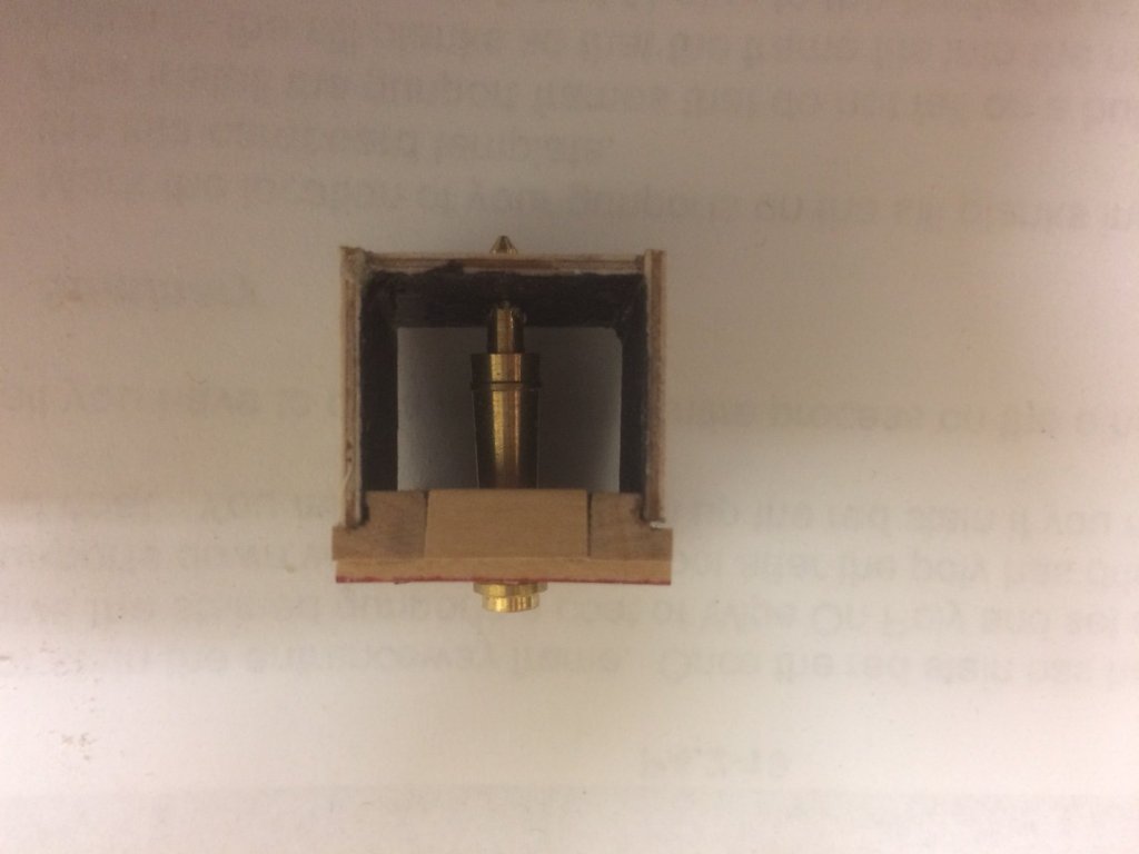


Historical portrayal of her guns requires them to be blackened.
-
On 5/21/2017 at 5:40 PM, ca.shipwright said:
Here come some photos. There are a bunch. More to come I can ever find the middle gun deck photos Enjoy


Sorry, another fail to open on the photos.
-
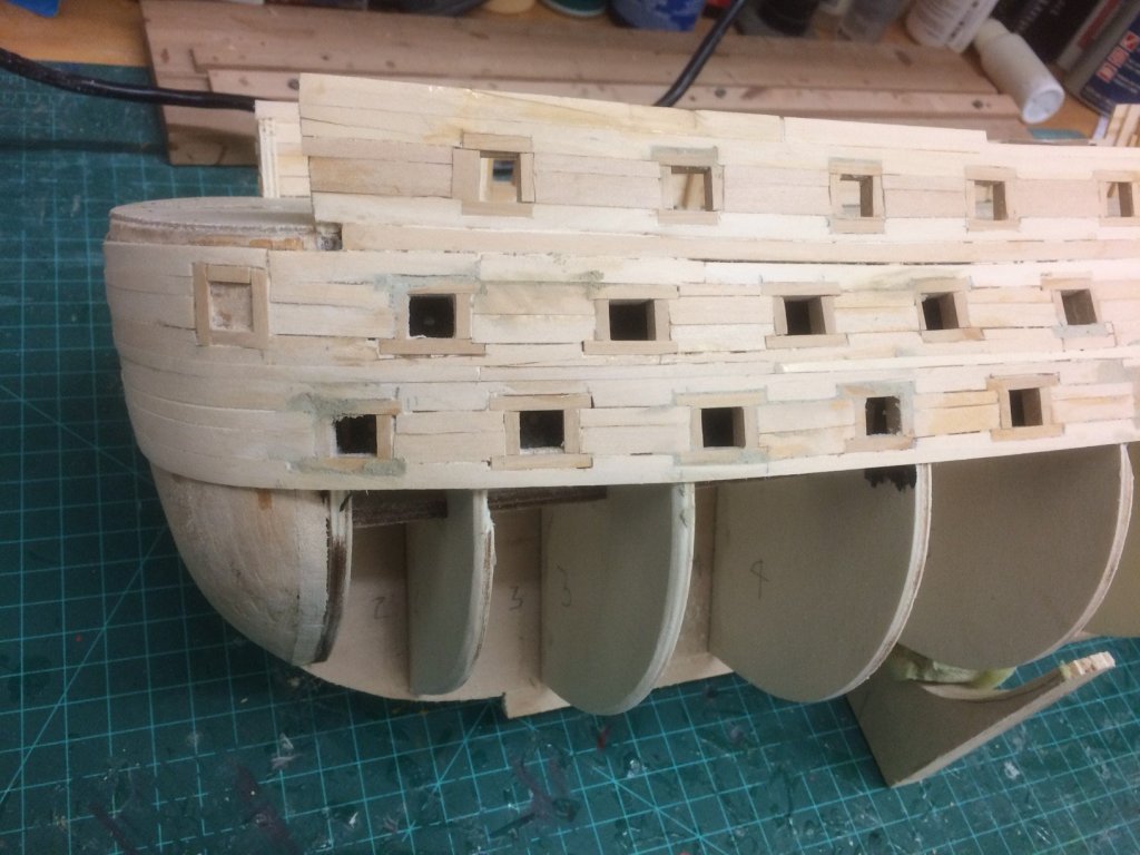
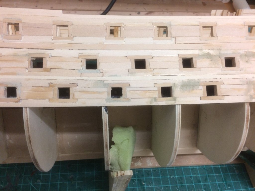
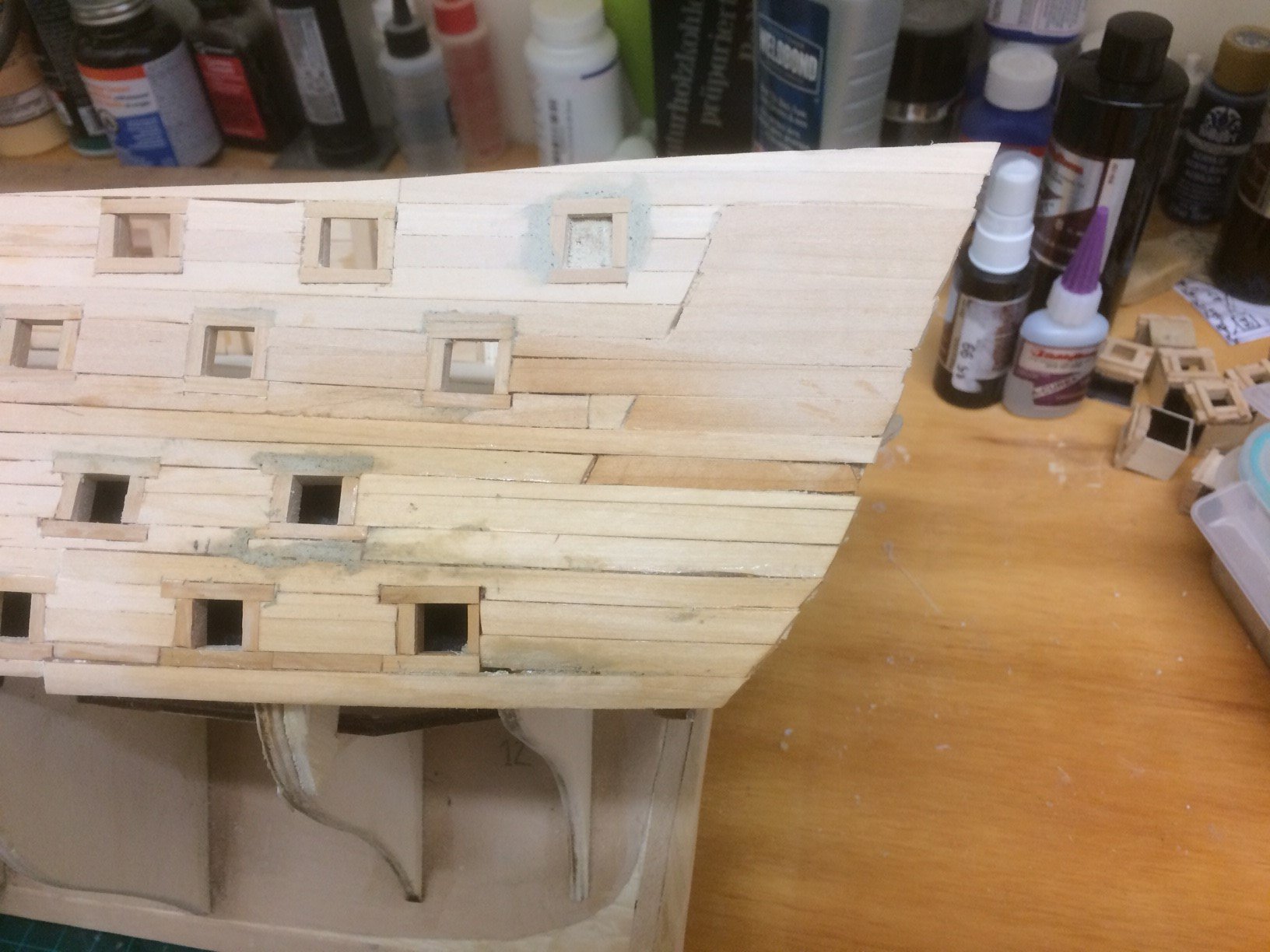
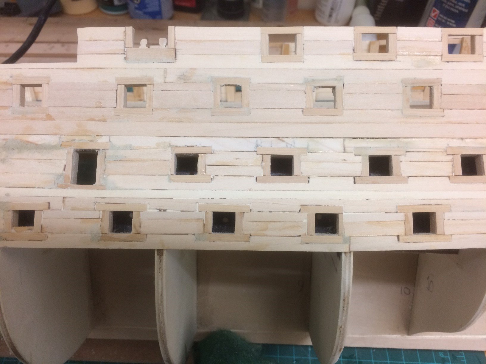
On 5/8/2017 at 3:04 PM, ca.shipwright said:
Greetings,
Another update. I completed the port side of the main deck gun ports. I thought they came out rather well. Slimming down the interfering bulkheads and cutting one off is a real pain. I can't wait to see how much trouble this is going to be on the quarterdeck and middle and lower gun decks.I had my first service problem with my Byrnes saw in it's 15 +/_ years service. The switch went out. First, the polarity reversed and I continued to use it even though it wasn't safety smart. Then it died. 30 minutes to buy it and 15 minutes to install the replacement switch. And, away we mill.
I need to get a start milling the .045 in planking. There's a lot to do.A little wood filler in the gaps and a good sanding should take care of most of the defects. Most everything will be covered the second planking. The rest of the markings have been added to the upper sills.
It is worth noting; maybe: At first glace the gun ports on the three decks appear to be symmetrical. Not so. I was looking at the Corel template and they had some of them offset. I thought it was poor manufacturing. Not so again. I took a look in AOS and sure enough there are offsets between the decks.
Next up completing the gun decks and quarterdeck gun ports p/s. This is going to take some time. Next
update might be a while.


 Regards to all
Where's the photos?
-
On 4/21/2017 at 10:33 AM, ca.shipwright said:
It looks like there will be a cascade of problems associated with that 1 mm. Mantua got the money and I got the replace parts for the framing in 4 days. Great service! Assembled all the framing, counters, bow filler blocks, and cut the rabbet. I have misplaced my ebony stern post. Hopefully it will show up or I will make another out of boxwood.
When I was cutting the bow filler blocks, the top view as taken from AOS was wider than the first bulkhead. This caused me to scratch my head and what the h***. I then copied the entire forward portion of the main deck and lay it across the ship from the bow to mid ship. Surprisingly, it was at least an inch wider than the Mantua hull framing. It looks like Mantua took some liberties the the kit design. The entire ship's beam is at least 1 inch narrower the the AOS drawings. She is still a monster.
Terry- I was following Bob's practicum with my homemade framing parts. This is not an easy build, but, Bob's practicum is so detailed that you almost can't go wrong if you read the section once, and then read it again. If you do purchase the practicum, and I highly recommend it, there are a couple of errata that I can fill in for you. Not having the correct dimensional material and my lack of skills all added to the continuation of the problems. The biggest was that almost all the gun ports had to be cut into the bulkheads. This was not a task I was willing to try. And, it would have seriously degraded the structural integrity of the hull.
Photos will follow soon
Regards
Thanks for that heads up on Mantua's screw up! I'll be sure to avoid that kit when I go to purchase the
is model. That big of an error is inexcusable by such a company.
-
On 4/21/2017 at 10:33 AM, ca.shipwright said:
It looks like there will be a cascade of problems associated with that 1 mm. Mantua got the money and I got the replace parts for the framing in 4 days. Great service! Assembled all the framing, counters, bow filler blocks, and cut the rabbet. I have misplaced my ebony stern post. Hopefully it will show up or I will make another out of boxwood.
When I was cutting the bow filler blocks, the top view as taken from AOS was wider than the first bulkhead. This caused me to scratch my head and what the h***. I then copied the entire forward portion of the main deck and lay it across the ship from the bow to mid ship. Surprisingly, it was at least an inch wider than the Mantua hull framing. It looks like Mantua took some liberties the the kit design. The entire ship's beam is at least 1 inch narrower the the AOS drawings. She is still a monster.
Terry- I was following Bob's practicum with my homemade framing parts. This is not an easy build, but, Bob's practicum is so detailed that you almost can't go wrong if you read the section once, and then read it again. If you do purchase the practicum, and I highly recommend it, there are a couple of errata that I can fill in for you. Not having the correct dimensional material and my lack of skills all added to the continuation of the problems. The biggest was that almost all the gun ports had to be cut into the bulkheads. This was not a task I was willing to try. And, it would have seriously degraded the structural integrity of the hull.
Photos will follow soon
Regards
SPlease enlighten me. What is Bob's practicum? And where can I find it?
-
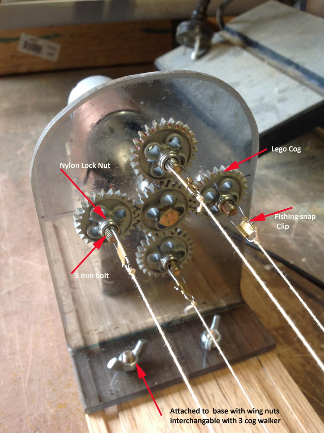
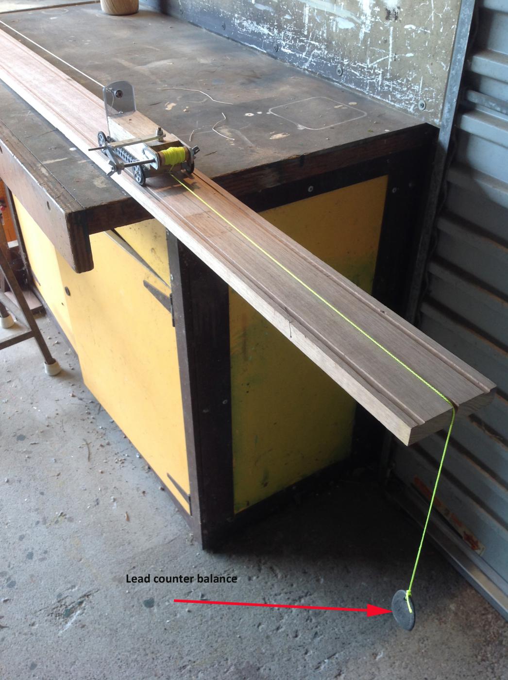
On 10/22/2016 at 12:46 AM, hornet said:
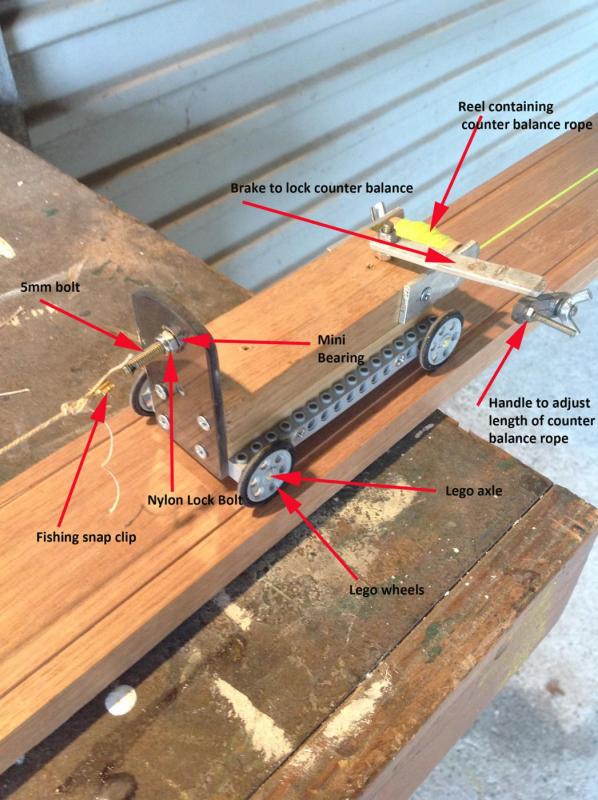
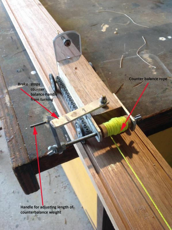
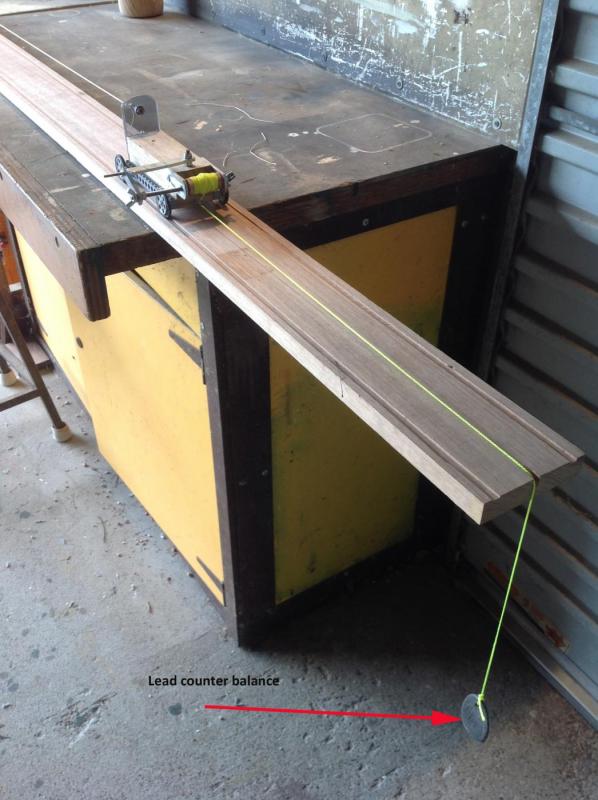
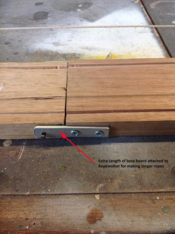
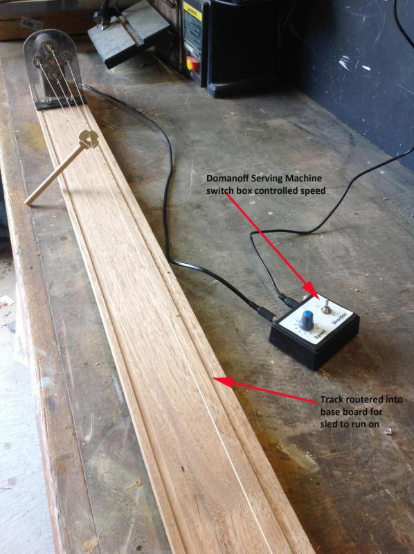
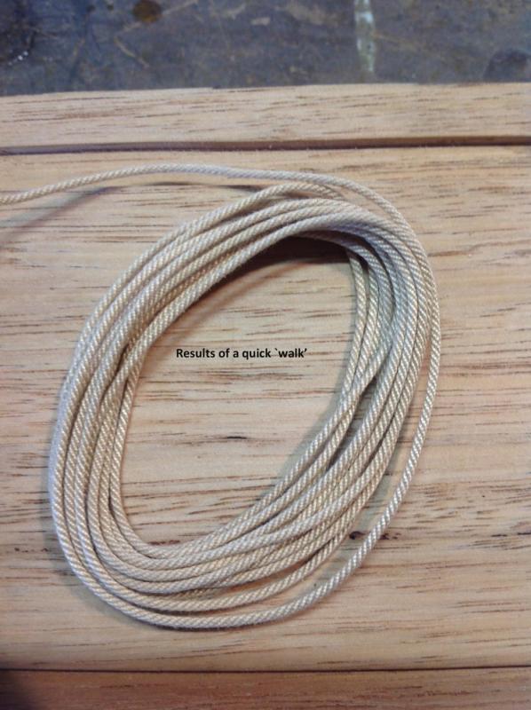
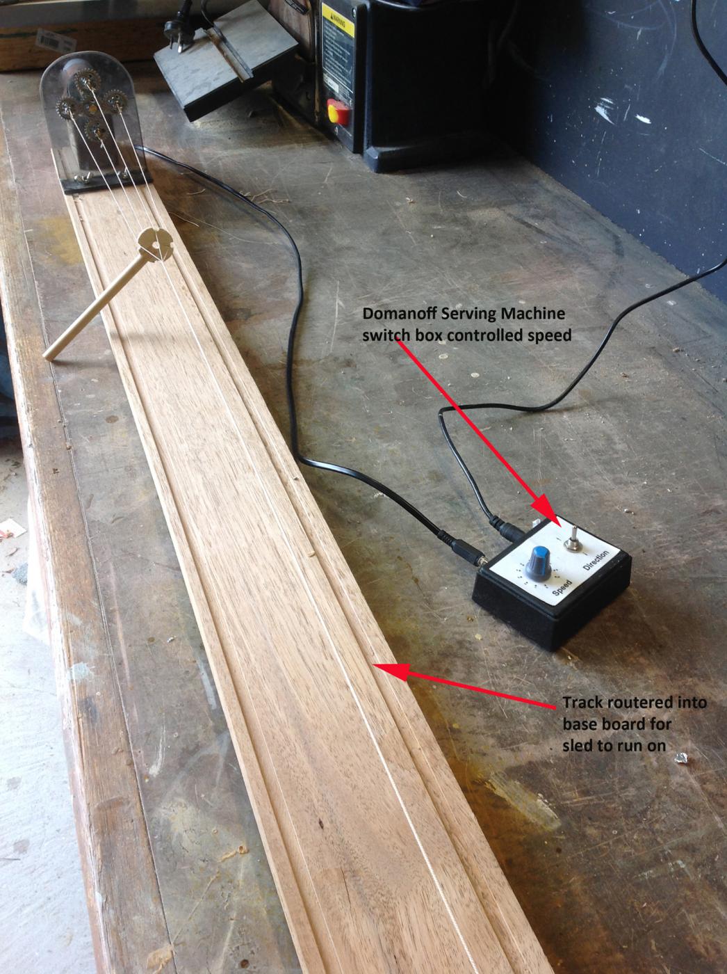
While completing my previous build, I was very unhappy with the anchor ropes supplied because they were completely out of scale. After some research I decided to build my own rope walker. It only cost me about $50 AU to make. The main cost was the motor and coupling. Perspex I had left over from another job and the variable speed/on off attachment from my Domanoff Serving Machine proved most useful. Mini bearings were very cheaply sourced from eBay. I have labelled each picture in an attempt to show how it was constructed. I intend to make as many ropes as possible for my current build - Caldercraft's Bounty when the time comes. Hope somebody gets some ideas from this post.
Cheers
Steve

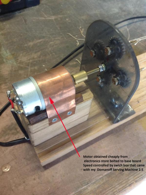
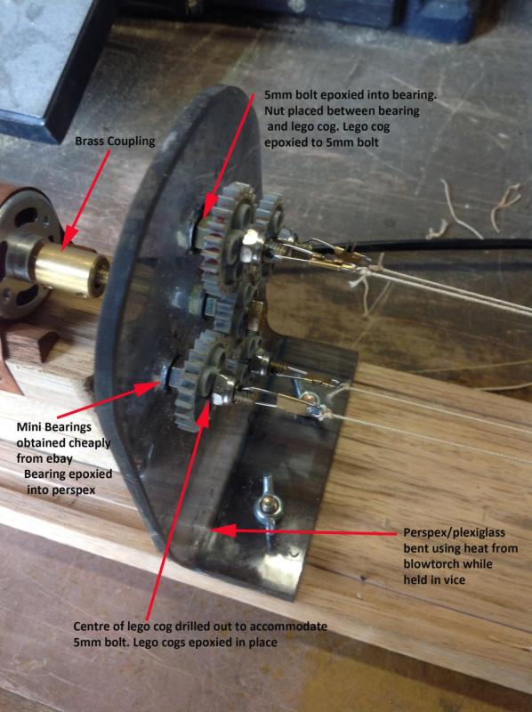
Very creative! What are your Lego cogs part numbers?
- JohnB40, jim Landis and mtaylor
-
 3
3
-
On 1/26/2020 at 12:29 PM, Chuck said:
I only sometimes glue the edges. If edge gluing will possibly close a gap then yes I will do so. But if there isnt a gap then why bother. I found that if I edge glued every plank, should I not like that plank after positioning it, it will be very hard to remove without also damaging the planks it was edge glued to.
I only use PVA for my models....except when planking. When planking I use CA. I place a small drop in the center of each bulkhead to glue each strake into position while making sure it is tight against the plank next to it. I only glue it on if it fits tightly and no gaps are seen after a test fit but sometimes I dont see the small ones and have to remove the plank after and try again.
Finding where to place the "top" of the bend and how severe to make the bend is a learning "curve". No pun intended. Its something you will learn to find as you practice this technique. You will get much better with that after a dozen or so attempts. Most times you will likely underbend in the beginning. Then after that you may even over bend. But that is what allows you to learn what shapes are best. I would even go as far to say that you should sacrifice a few strips of wood and simply go nutty with some test bends. Try over bending and try under bending as well. Try moving the "top" of the curve forward or aft just as a test to see how it looks when test fitting. Try a tight bend and then try a more "longer" and subtly bend. Just examining the gaps after trying these different scenarios will help you learn a lot. Its what I do on every model when starting this exercise because once I have a good idea what curve is needed its pretty similar for all of the other strakes.....more or less for the hull shape you are working on.
Hope that helps.
Do you pin or nail the planks down with trummels or nails to give them that original look and to ensure they are mechanically fastened for strength?
-
On 12/26/2020 at 10:53 PM, glbarlow said:
Just so someone says it, a few of you need to add “in your opinion” to some of your bold unbending statements.
So in my opinion: 1.CA is the best choice for planking a hull using Chuck’s method linked above, PVA is just so unnecessary. 2. I have models over 25 years old done with CA that are just fine and look great. 3. I don’t think any well built ship model survives dropping to the floor, it’s best not to do that. 3. Edge gluing is not only totally unnecessary it’s also detrimental to the look of the hull. 4. I doubt the humidity variance in most first world homes creates an issue. 5. I’ll put up my nine models as examples of using CA for hulls any time.
I don’t understand why people don’t just acknowledge design and build preferences as just that, a preference. There are many ways that are right and many that work just fine. There are very few that are wrong, using CA for hull planking is not one of those. Why denigrate a method different than your preference, why not instead offer your method as one of many options. In my opinion...
I would offer this up based on personal experience. I would have to disagree with your statement on humidity affects in 1 world homes. Our cabin here in the Catskills built in 2016 when we moved in experienced major humidity problems due to lack of sufficient humidity to stabilize the logs and pine T&G flooring. Checks up to 1/2" wide opened up in logs and beams. Flooring shrank tangentially opening up cracks. Only the addition of a humidifier to our central air system has stabilized the cabin. The cracking and popping of logs and timbers has significantly been reduced. Wooden ships in 9% humidity would certainly fair the same. We run a minimum 40% humidity level year round. I see less movement when a wooden plank has need completely sealed all four sides.
-
On 12/24/2020 at 5:23 AM, Bob Cleek said:
One should carefully consider the downside risks of gluing planking seams, whether by application of adhesive to the seams, or by coating the inside of a hull with epoxy resin adhesive which soaks into the seams from inside. As noted correctly, wood moves with changes in the ambient humidity levels of the environment it's in. This movement is primarily across the grain and its amount varies depending upon the wood species and, within the same species, even the location where the wood is grown. This is called tangential movement. Most woods will shrink tangentially six to ten percent when dried and will swell back depending upon the moisture content absorbed. The amount of movement is relatively small, assuming properly dried wood being used to begin with, but can still be considerable if the distance you are dealing with is relatively large.
So, if you are building a model using vertical grain stock, as one should, the tangential (cross grain) side of its planked hull can easily total six inches. That's six inches of grain to shrink tangentially and even at a rate of movement of one percent, you are getting close to a sixteenth of an inch, which would be a quite noticeable crack in a model's topsides. If the planks are not fastened to each other, each will shrink individually and if you have maybe 24 1/4" planks, that shrinkage will only amount to 1/24th of a sixteenth of an inch. (You can do the math to get an exact fraction... a good example of the advantages of metric measurements!) That amount of movement isn't going to be noticeable at all and most coatings will allow for such movement without cracking at the seams. However, if the seams are all glued together, they all move as one, and the "weakest link law" takes over. In that case, a sixteenth of an inch crack along the weakest glued seam... or a crack in the wood itself... is going to occur at the weakest point. Conversely, swelling will push the glued sheet of planking for that sixteenth of an inch against everything it butts up against, again potentially causing a structural failure at the weakest point, or tend to buckle the "planking sheet" outward, breaking the glue bonds... or the wood... at the frames.
Now, with prime wood species which have low movement factors and with relatively stable humidity, you may not run into any problems at all, but theoretically, the potential is there and I've seen its results in more than one model I've restored. More often than not, parts, cap rails, for example, start popping off and nobody knows why.
Monocoque wood hull construction is tricky. For my money, I prefer to give the wood as much opportunity to move on its own as possible without concentrating swelling and shrinking stresses within the structure.
Others' mileage may vary, of course.
I have seen some models that used wood pins to nail on the planking. And some I have seen used brass nails. What is your experience or observations regarding these two methods and wood movement? Also the use of a flexible epoxy such as I use on fishing rods would seem to eliminate the problems of a hard set liquid epoxy.
-
-
On 6/25/2017 at 3:17 AM, Tim Curtis said:
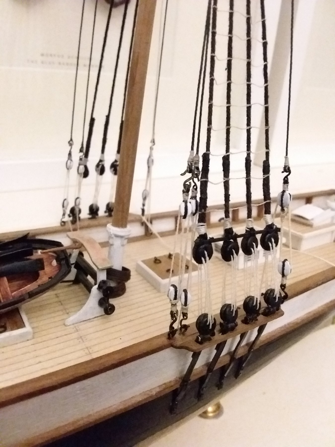
 Thanks to all for your kind words. Thoroughly enjoying rigging. It's my favourite bit. Every separate line and block is like a little model of its own!
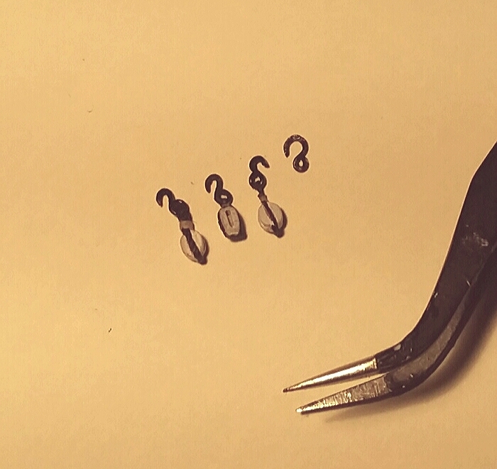
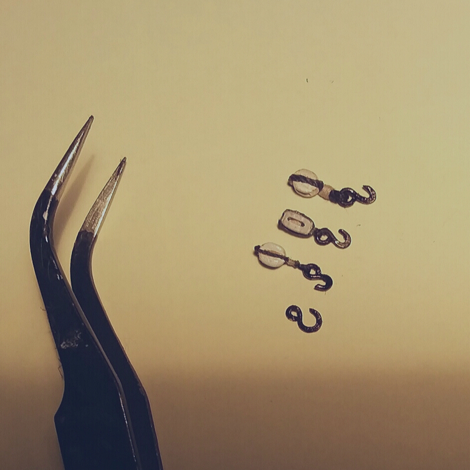
CI am especially interested in all the hooks used in this build. I haven't seen any used on other ships. Were these in the plans or sourced elsewhere?
-
-
On 11/14/2018 at 11:50 AM, David Lester said:
Good Morning,
I have a bit of progress to report. I've finished up quite a few details on the hull including the coppering as well as a couple of more pieces of the deck details. (All are just sitting on the deck for the photos - none is actually installed yet.)
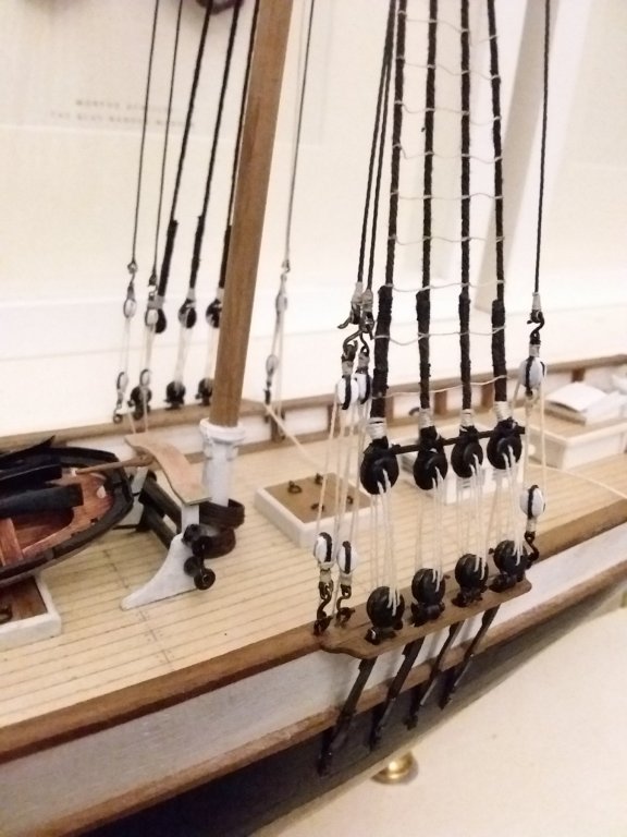
There are a number of portholes etc that are not included in the kit, so I ordered a few different ones. It took a bit of research finding the right sizes but in the end I found some nice small ones - only 1.2mm - for the smallest openings and a couple of different bigger sizes for the others.
.JPG.572fa21e3299ef3885b3fe910713d17f.JPG)
The oblong mooring chocks are a bit of a mystery to me. The plans indicate four of them on the starboard side and none on the port size, but the kit comes with six. So that's more than needed for the outboard side of the openings, but not enough for both the outboard and inboard sides of the openings. So I used the four kit supplied ones on the outboard side and then used new brass portholes which I bent into an oblong shape for the inboard side and it seems to work well enough. You can see them clearly below.
.JPG.4700ed413b6fb921270d59bd57f4ad07.JPG)
Stern details finished -
.JPG.edb80ea68b8b2e9a09c95721f87bbcd0.JPG)
I always find finishing the decking to be a challenge. The basswood takes the stain so poorly that it's hard to get a nice consistent finish. I also like to try to simulate the grayed out look that decks usually have on the real ship. I'm fairly happy with the result I got this time, but don't ask me to duplicate it! It was a lengthy series of experimental steps. This time I used acrylic artists' paint.I started with a thinned mixture of black, white, dark brown and yellow, mixed to achieve a sort of taupe colour. I brushed it on and rubbed it down. Then there was miserable series of steps - adding more brown because it was too gray; adding more black because it was too brown; adding more white because it was too dark; adding more yellow because - well because it was the only colour left to add and then going through the whole process over and over again. When I was finally reasonably happy, I rubbed the whole thing down with steel wool which resulted in a very nice finish and a colour that I think looks ok.
(Also, while I'm on the topic of decking - this kit has no sub-decking. The decking planks are 1/16" thick and install directly on the bulkheads. If I was doing it again, I would buy 1/32" sheets and make a sub-deck and then install 1/32" planks over that. It would be much easier to get a good even surface and there would be no concerns about plank butts not lining up with the bulkheads.)
.JPG.afe1b5ca8b09f4c9db3e0a8222186e9a.JPG)
The bigger challenge though, was getting a crisp line along the top edge of the upper white stripe. This is the outboard edge of the top rail and according to the pictures I've seen, the white should only be on the vertical surface, not the horizontal surface. After many failed attempts at painting, I realized I would never get a good clean line where the white and black meet. The upper edge of that white line is highly visible and the least deviation jumped out at me.
I considered using a styrene strip which would give a good sharp line. I'm not opposed to using styrene in principal, but in this case it was just too front and centre so I abandoned that idea. In the end, I painted a piece of paper and applied that. I have some really nice black paper that I used to simulate small iron fittings etc. It's not as heavy as card stock, but heavier than regular paper. It painted beautifully, without any wrinkling. I cut narrow strips of it and glued it on and it solved the problem!
.JPG.23711be710b4c82f0958ce8bf7a7cc0e.JPG)
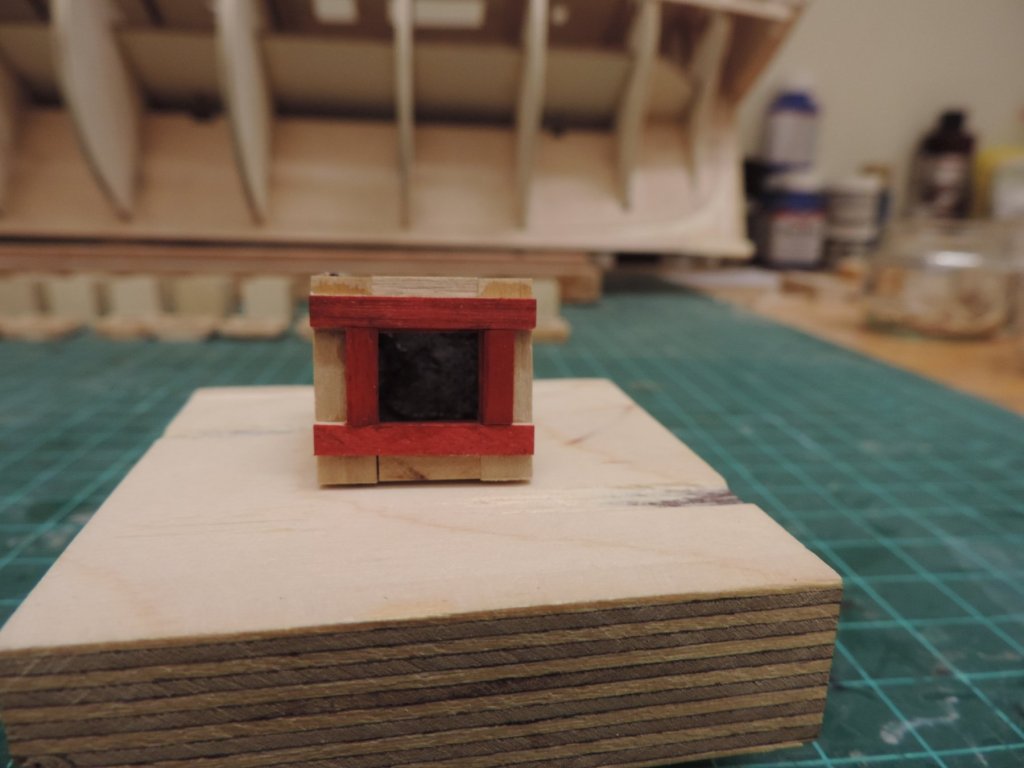
The pump handles are another kit mystery. They provide a small centre fitting, but then you are supposed to attached extended handles to it. I couldn't see any way to do that easily or nicely, so I discarded it and fabricated the whole part as one from brass -
.JPG.b00efd143be3da618831087cd7ac0105.JPG)
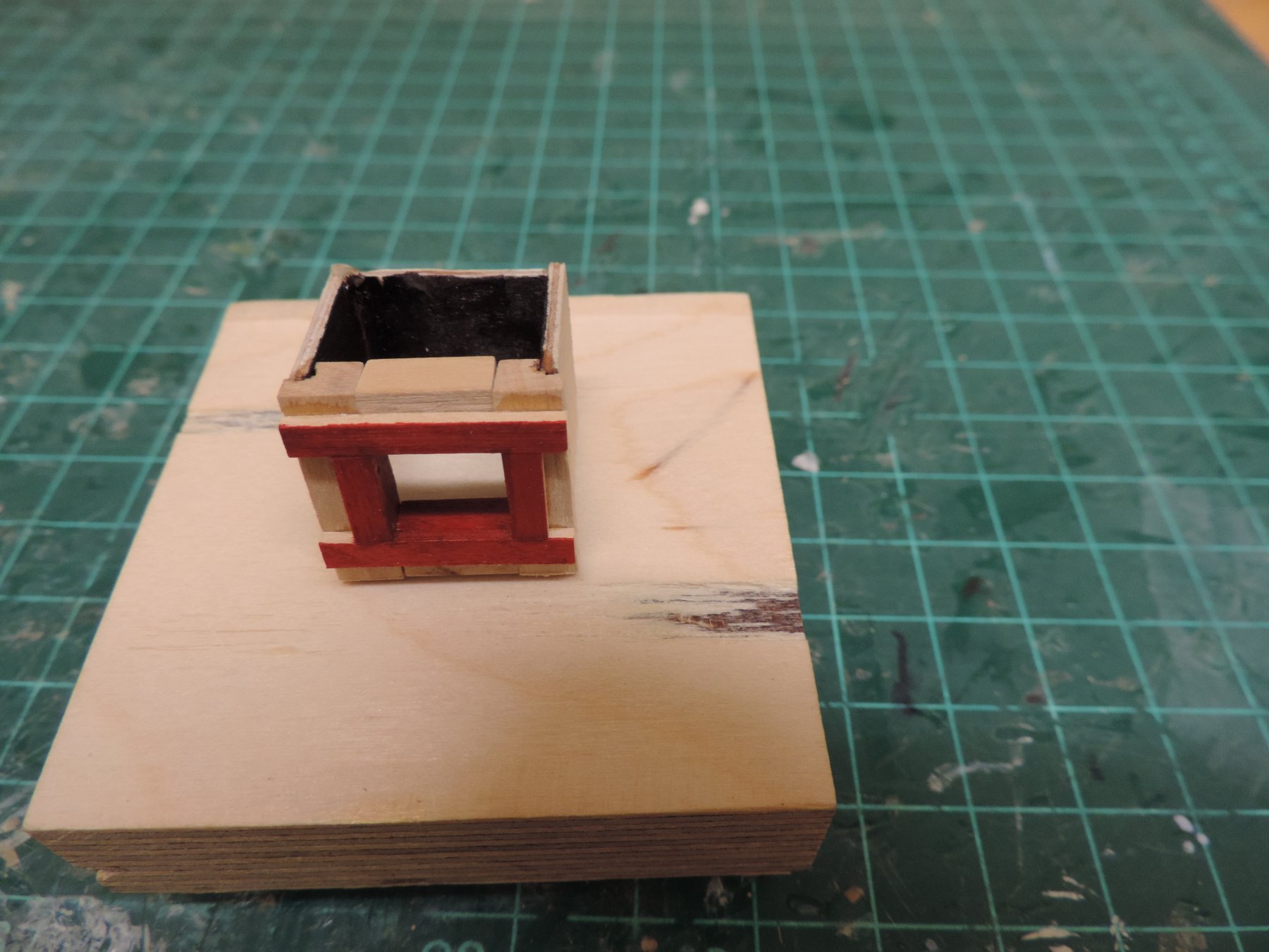
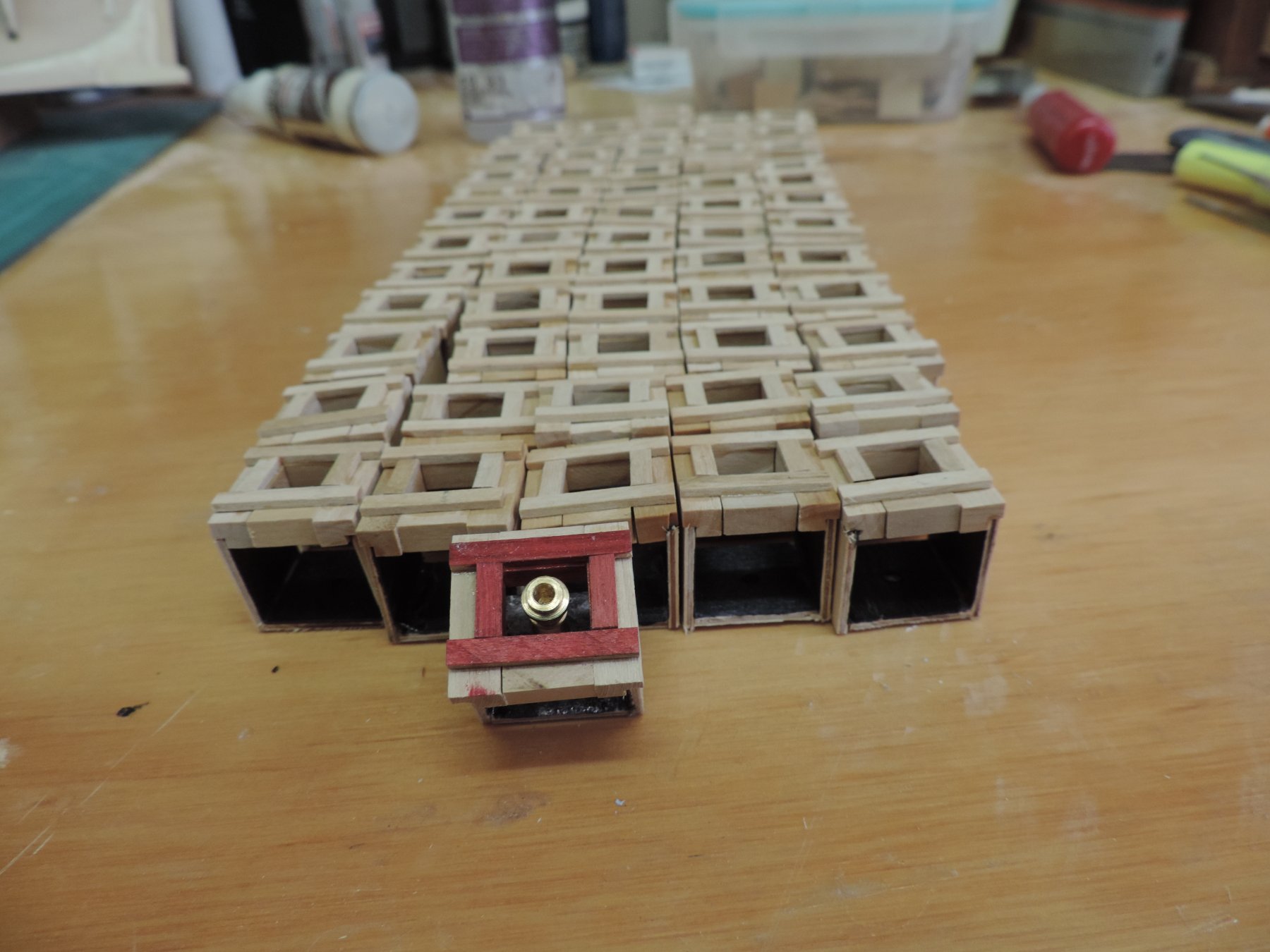
So that's where I'm at so far. Next up is the tryworks, which looks like it will present some fresh challenges too.
This is one of the most enjoyable builds I have done yet, and if anyone is considering this kit, I would definitely recommend it.
Again, many thanks for comments and likes.
David
.JPG.9dd81bd823d9c26f875c26903778396d.JPG)
.JPG.1b2d5c3d5a3b5890a09c2a2657a5d149.JPG)
When using basswood as you experienced, it does not stain well. I strongly recommend you paint all such pieces with sanding sealer first. Then rub it down lightly with 220 grit! This seals the wood And allows an even application of stain.
-
On 9/30/2018 at 7:14 PM, Richvee said:
I'm wondering if the bars were different colors through the renovations...??
Here they look black...
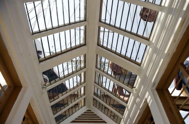
Here, ochre...
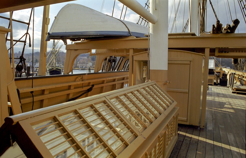
and here it's tough to tell
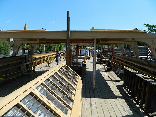
I'd say the choice is yours. I wouldn't think either would be "wrong"
Personal opinion. I like the black for a little contrast. On a model I think it would make that detail "pop".
As a professional photographer, I offer this input. Anytime you view something backlit as in your interior picture, those items will appear black due to the shadow effect! It won't matter what the actual color of that item is. The exterior view of those rods is the correct color they should be painted. If that is ochre, than use it.
-
On 8/20/2018 at 9:30 AM, David Lester said:
I just hope that when I'm finished it doesn't resemble William H. Macy as he appears in "Shameless!"
Thanks for checking in everyone. While it's still early days, I have to say that I'm very impressed with this kit so far. It's presenting plenty of challenge. I'm working on the planksheer, rails and stanchions and they're quite tricky, but at the same time the design of the kit is so good that it doesn't work against you. It's very satisfying and fun. Also, I can see that the kit provides lots of room for enhancement or upgrading which I hope to do to a certain degree. With so much reference material readily available that shouldn't prove to be a frustrating exercise.
David
Having just purchased this kit, I was wondering what your opinion was of the quality of materials and instructions. I judge you have a very positive opinion of this kit?
-
Very well laid out and noting the particular shortfalls with some items. This will come in handy when I start mine.
-
On 4/18/2018 at 5:54 PM, Dave3092 said:
I decided on the H.M.S. Beagle because we had traveled to he Galapagos islands back in 2012. I purchased the kit on eBay after it was no longer available from the manufacturer. This particular kit was originally purchased in 1995, so it us already 23 years old. So far, I have scanned and OCR'd the instructions and parts lists from the original instructions.
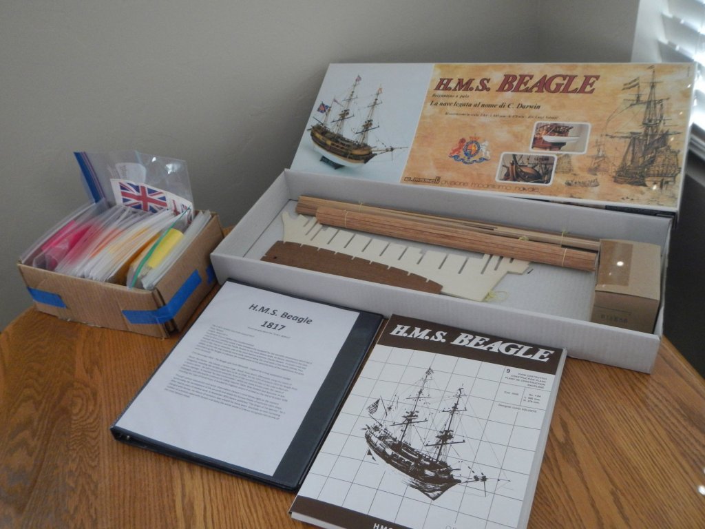
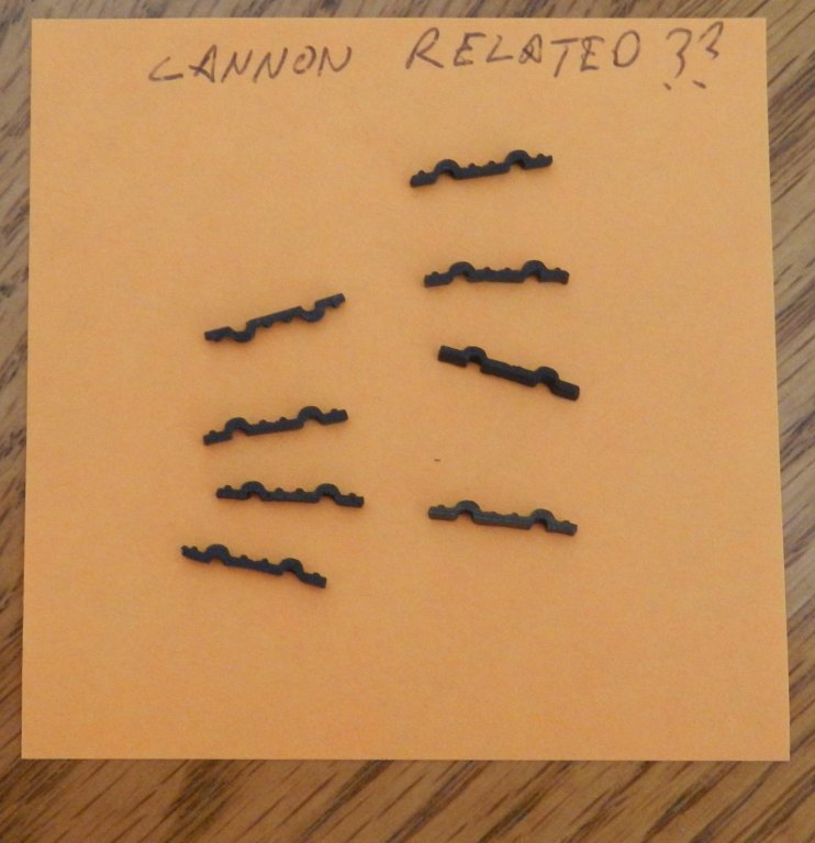
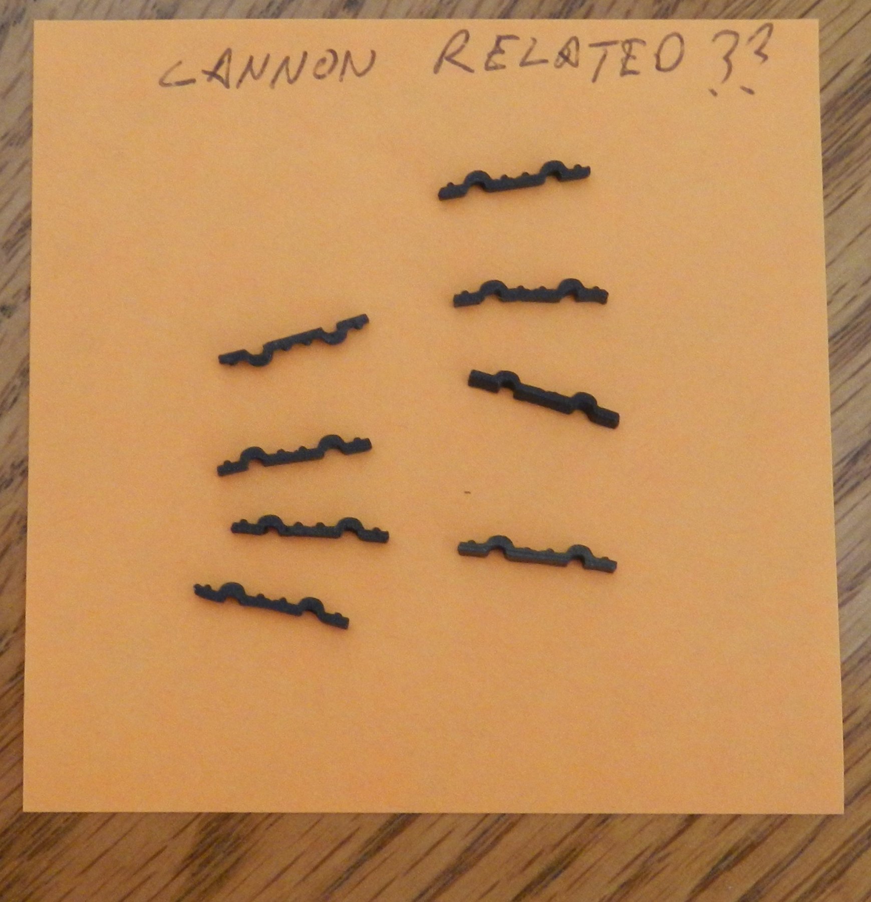
From that, I created a master parts list to compare to the inventory provided. Almost everything seems to be there, but I have two items that I need some help identifying.
These were in the same bag as the cannon and carriages. They look like a strap to hold the wheel axles, but the bumps do not line up with the axle indents on the carriage.
And I haven't been able to identify what these might be.
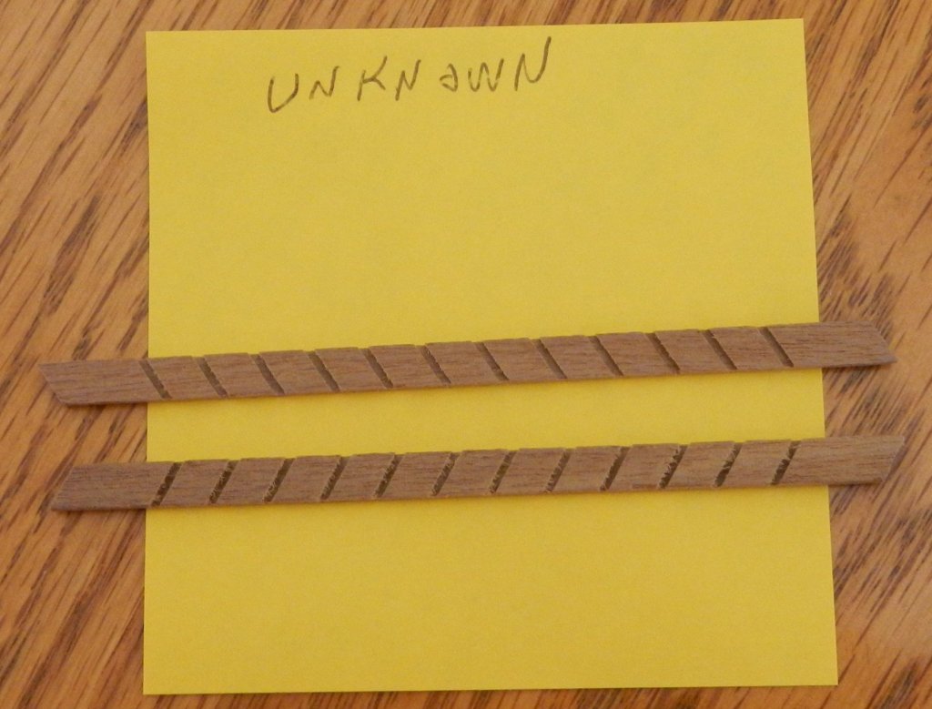
Any help identifying these would be greatly appreciated.
Thanks!
Those pieces above are the cannon strap down brackets placed over the trunnions on the carriages.
-
Very nice work! And thanks for the heads up on the materials! I just got this kit on eBay and have been looking for information on building this kit, quality, and build logs like yours which I will be following!


Santa Maria by Emmet - Amati - 1:65-Columbus Caravelle 1492 -Third Wooden Ship Build
in - Kit subjects built Up to and including 1500 AD
Posted
So, given hindsight now. It would have been better to line the top of the bulkhead with a full width strip to match the deck?