HOLIDAY DONATION DRIVE - SUPPORT MSW - DO YOUR PART TO KEEP THIS GREAT FORUM GOING! (Only 13 donations so far - C'mon guys!)
×

.jpg.6c90d67e7e9071af590f4d4a2a8bc908.jpg)
Waldemar
-
Posts
987 -
Joined
Content Type
Profiles
Forums
Gallery
Events
Everything posted by Waldemar
-
.thumb.jpg.c6343966b029e7941df5b987d129aac6.jpg) To further complicate the supply issue, iron guns burst in action at a rather surprising rate. In two encounters five iron guns were irretrievably lost in this way.
To further complicate the supply issue, iron guns burst in action at a rather surprising rate. In two encounters five iron guns were irretrievably lost in this way. -
Sorry. Below the English translation: The ship "Saint George" 1 bronze quarter-piece shooting iron ball of 9 pounds 10 bronze pieces shooting ball of 3 pounds 2 bronze hail-shot guns (for langridge type ammunition, most probably with conical bores) 2 bronze falconets (they were usually put in the ship's boats) 1 iron piece shooting ball of 9 pounds 11 iron pieces each shooting ball of 6 pounds 2 iron hail-shot guns Total of the bronze and iron guns – 29 Missing – 7 guns Where the calibre is given, it refers to long-guns (all muzzle-loaders). Hail-shot guns had probably conical bores and could be both muzzle- and breech-loaders.
-
Right. It is hard to say at all of a specific gun establishment for the fleet. Myriad of types and calibres actually carried on ships proves that anything available was taken on board. From another, slightly later fleet inventory it is clear that most of the bronze guns delivered to the fleet were Swedish trophies, and – conversely – iron guns could not be delivered in sufficient numbers as the supply routes from the country interior were blockaded by the Swedish forces.
-
Mark: Even worse – war logistics. There were simply not enough guns at hand to fully supply the fleet. The ships themselves, modest in size, were good sailors indeed. In contrast to the "Vasa", which in fact was an experiment, both over-heavily built and ill proportioned for its two-deck layout (too narrow). Lieste: Below is an abstract from the fleet inventory for this ship (in German, but I suppose easy to apprehend): Daß Schüff Sanct Gérgen 1 Metallen quader Stück schüst Kügl von 9 tb eißen 10 Metallen Stück schüsen Kügel zue 3 tb 2 Metallen schrot Stück 2 Metallen Falkonetel 1 Eiseren Stück schüst Kügel von 9 tb 11 Eiserne Stuck schüst Jedtlihes Kügl von 6 tb 2 Eiserne schrot Stück Suma der Metallen undt eiseren Stück 29 Mangelen nah Stück 7 To put it simply – main battery of 6-pdrs, two heavier 9-pdrs as bow guns, and all the rest on the weather deck and on the accompanying boat.
-
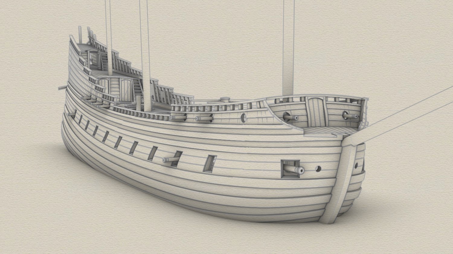
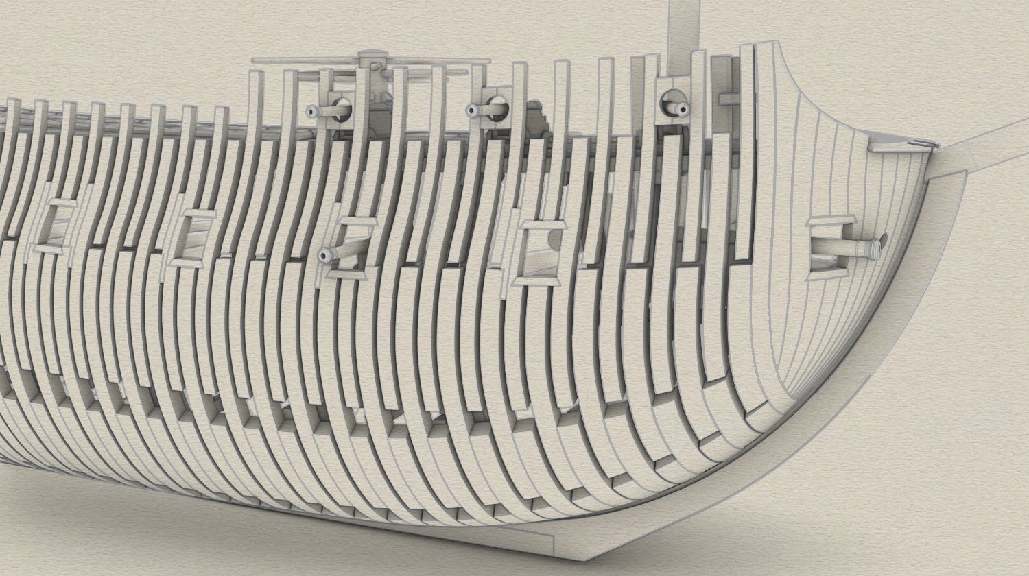
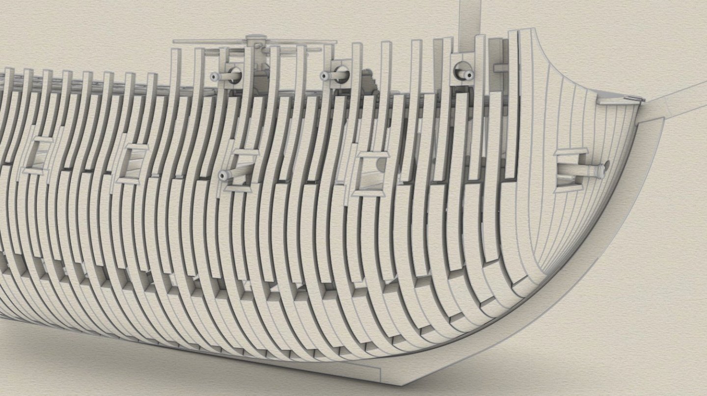
Almost forgot ... beakhead bulkhead. Not all gun ports were used at one time and the guns were moved from port to port and from side to side. The ship was never fully armed during her service anyway – seven pieces were missing out of the maximum possible number of 36 cannons.

-
... done, at least the prototype version.
-
Still, I much prefer your guesses to someone else's firm opinions. Thanks, Ab.
-
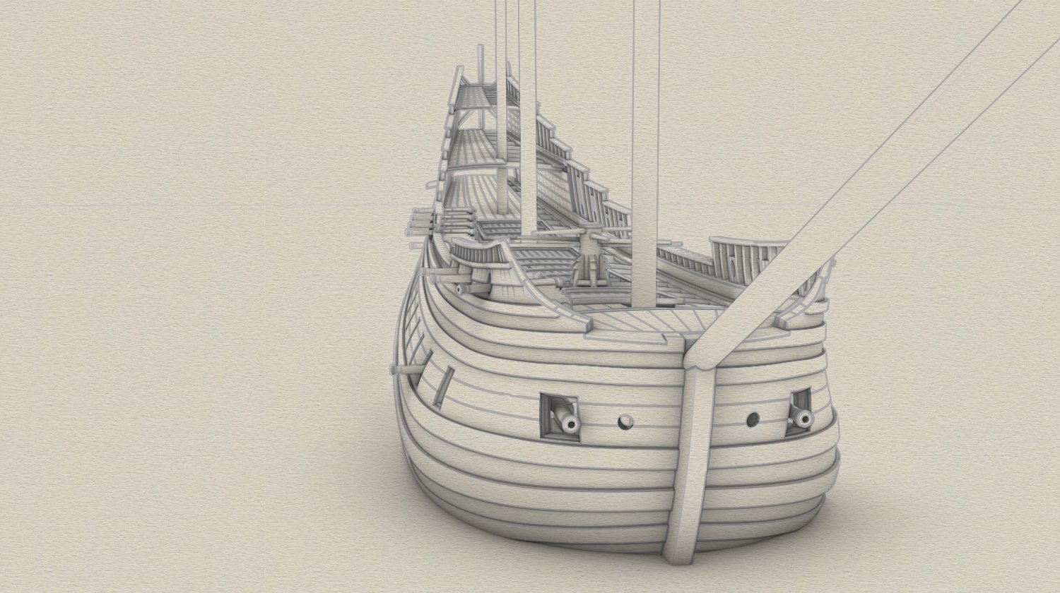
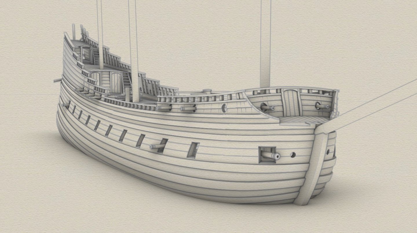
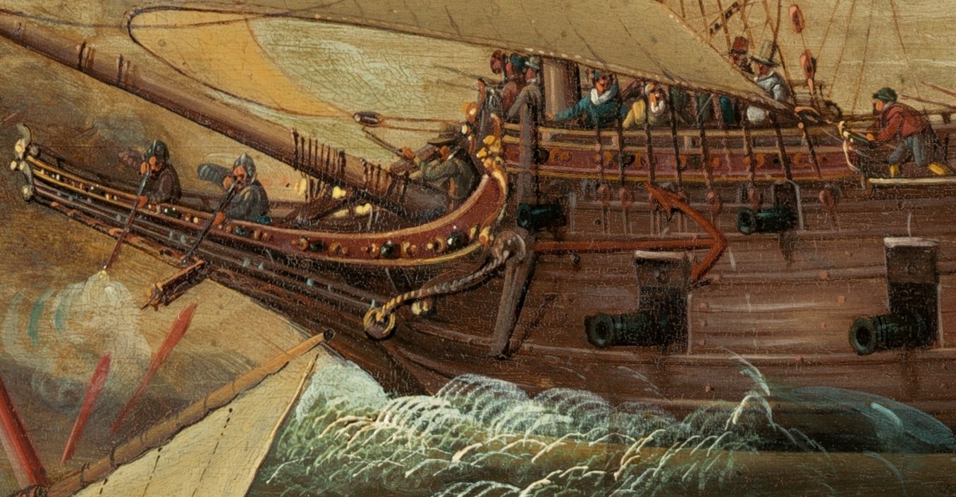
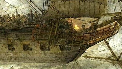
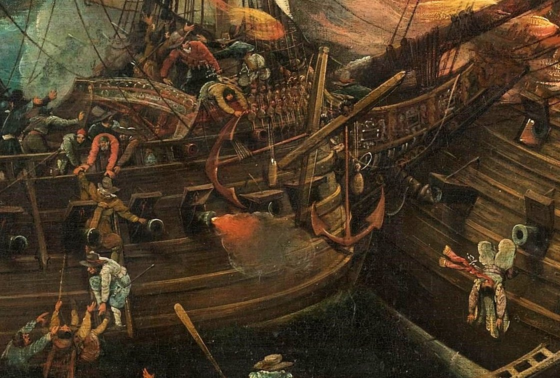
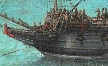
Thanks a lot. Your fine 3D pinas was also an inspiration for this project 🙂. The ship's bow looks somewhat sharper indeed, because nearly maximum stempost rake was chosen, within limits allowed by contemporary works on shipbuilding, and in fact considered at the time proper for purpose-built warships. Ab, please take a look at the selection of paintings below. All of them show more or less red coloured anchors. The issue is maybe not the most important indeed, I was just curious, and I have not found any explanation on this phenomenon heretofore. Cornelis Verbeeck, A Naval Encounter between Dutch and Spanish Warships, 1618-1620 Adam Willaerts, Gibraltar 1607, 1639 Cornelis Wieringen, Gibraltar 1607, ca. 1621 Hendrik Vroom, The Arrival of Elector Frederick V of the Palatinate and Elizabeth Stuart, 1623
- 257 replies
-
- 10
-

-
Many thanks, Ab! Your word and opinion counts double. You must have already noticed, that the ship's structure quite closely follows Dutch practices, which I assume also apply to the northern part of the continent. Even the shape of the bow, which I have made very full for a number of reasons, could be easily formed using the shell (bottom-first) method, although geometry of the whole underwater body is a synthesis of the known pre-designed frames procedures. For now I have to give priority to the external, visible parts of the ship (deadline!), because the first model is to be made by plank-on-bulkhead method. I intend to deal with carlings/ledges for other decks later. And, while you are here – do you know why anchors are red in so many contemporary paintings? Were they painted? Or simply corroded?
-
Very neat, fine work and the attractive, unusual subject (meaning ship's nationality). Planning to visit both the Military and the Naval Museums in Istanbul too.
-
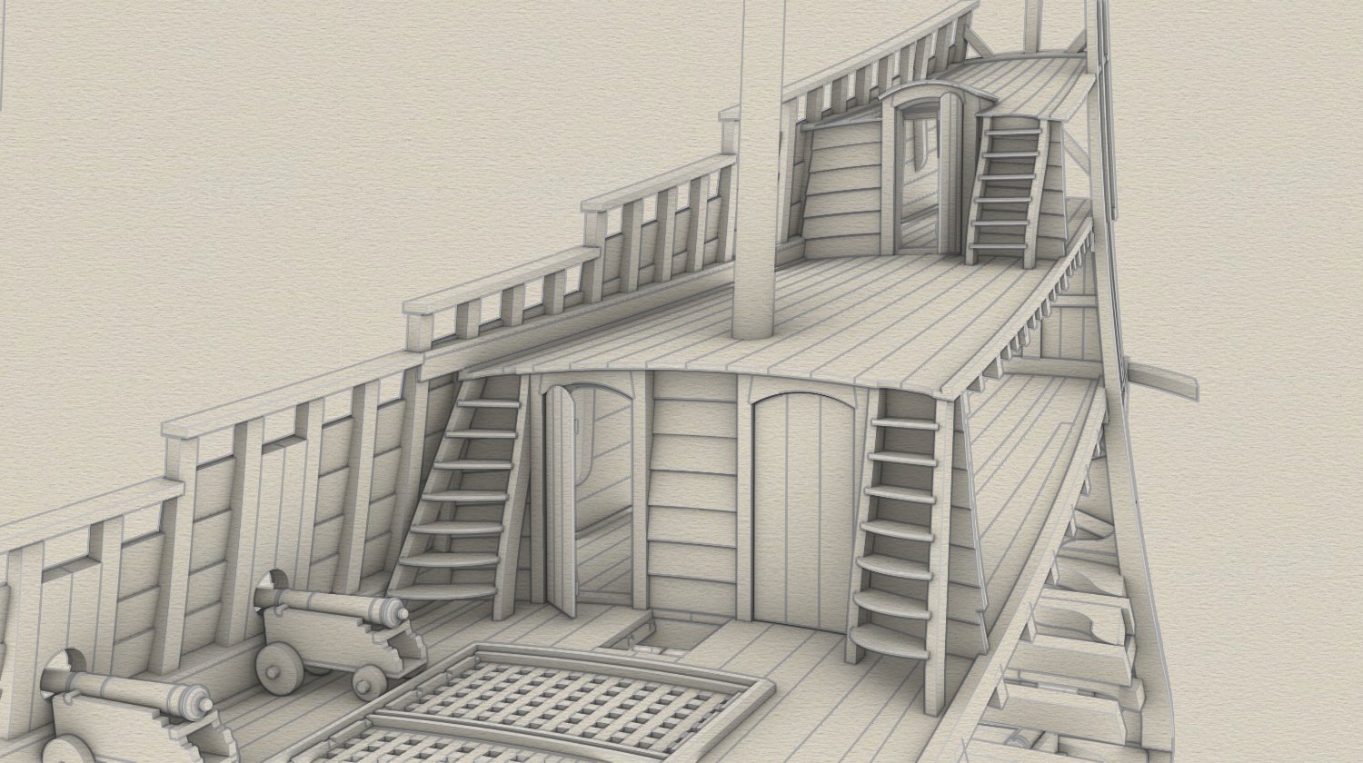
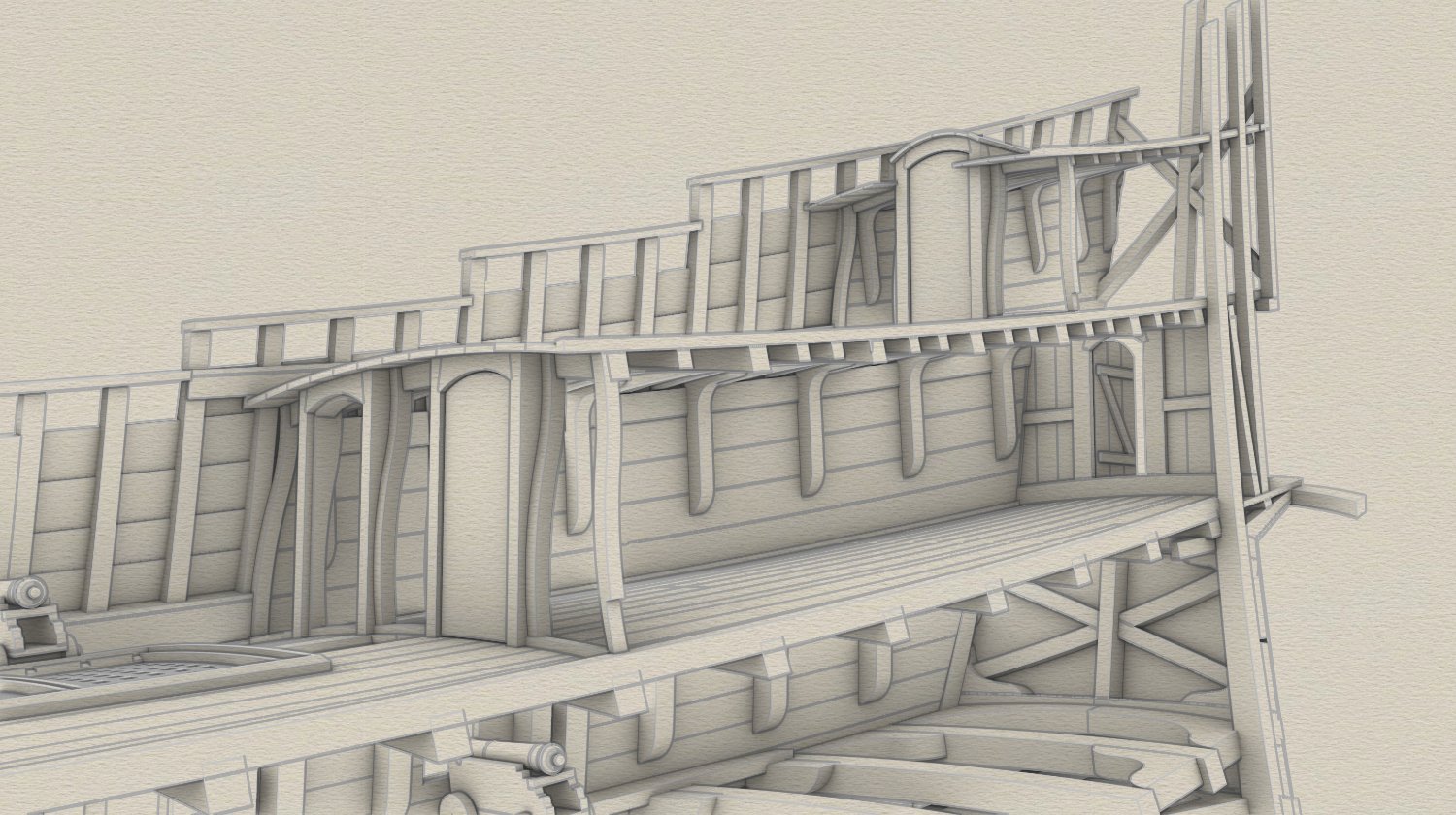
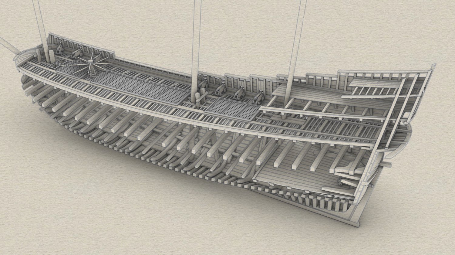
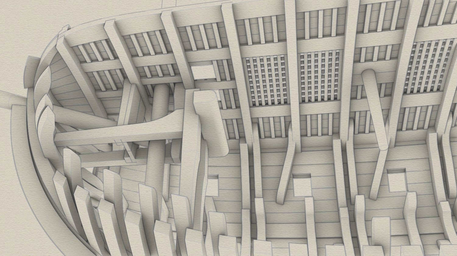
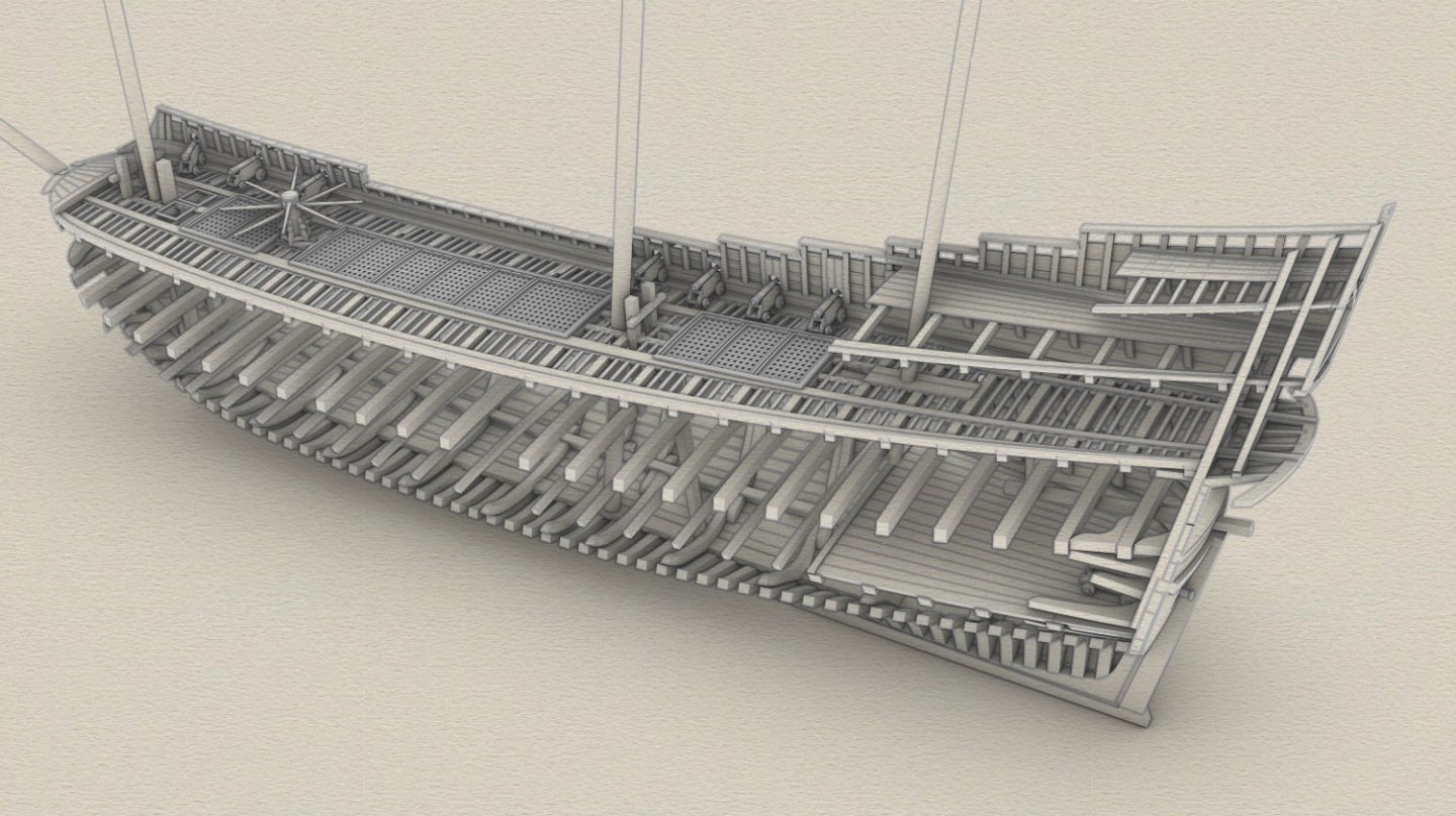
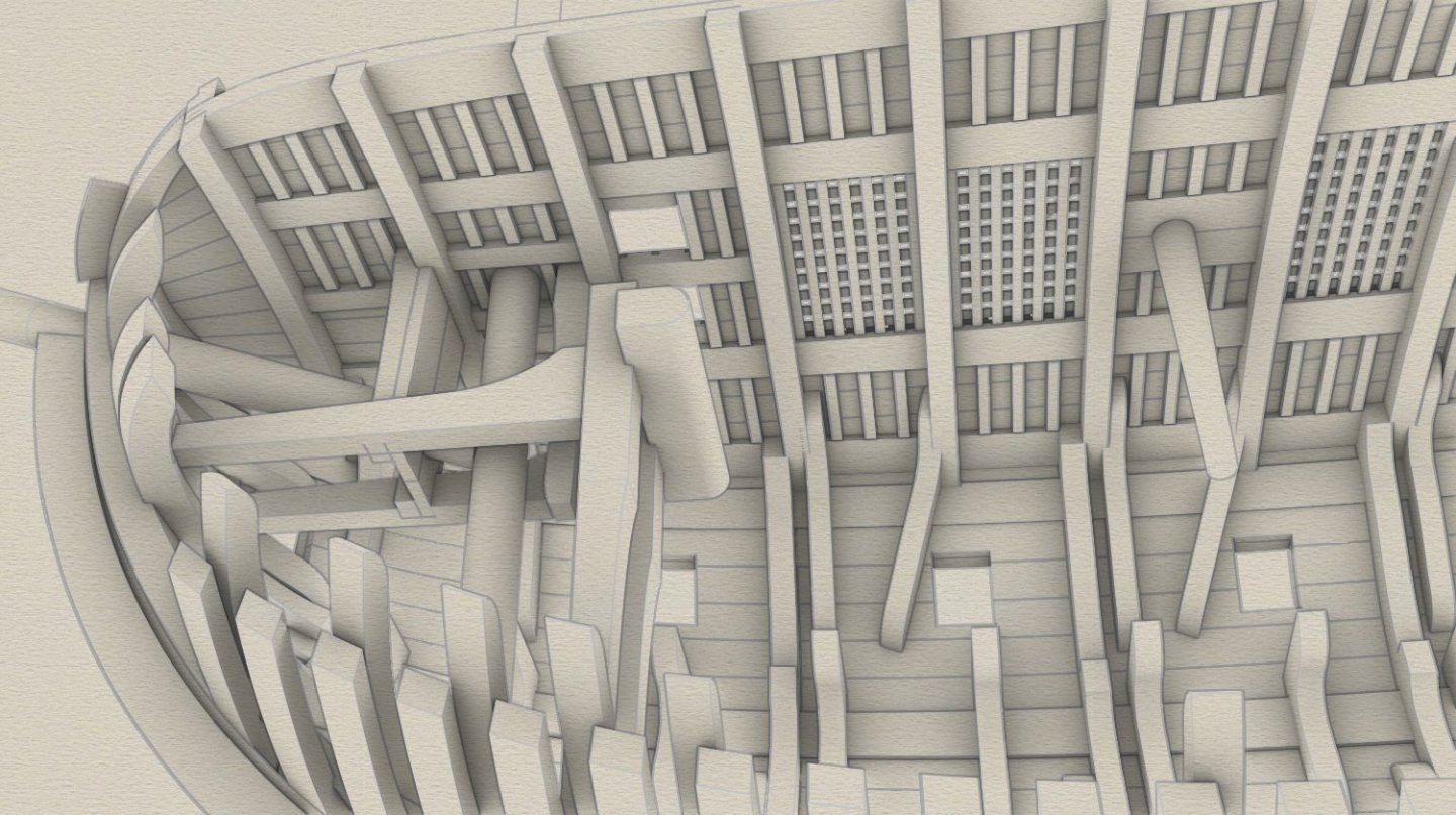
The upper sills were originally upside down and this is already corrected as can be seen below. The ability to make such corrections in a relatively easy way is perhaps one of the major strengths of computer-aided designing, provided the actual 3D model is properly designed. The lack of space in the bow part of the ship is evident in this view:
- 257 replies
-
- 12
-
-

-

-
... bits, knights, more hatches, ledges, etc. No carlings on the weather deck (intentional), or perhaps two long equivalent 'carlings' along the length of the whole deck.
-
Good choice, but still a hard one in one aspect... 🙂 Royal Three Crowns or the Yellow Cross? Or maybe both?
-
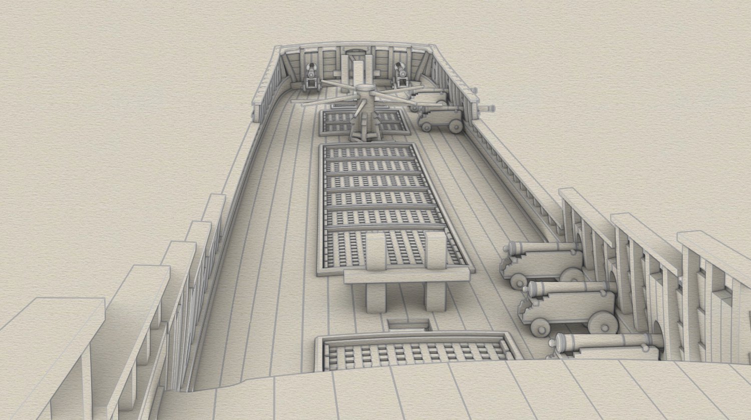
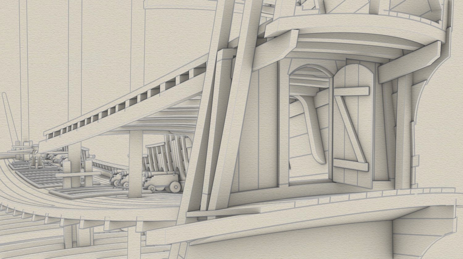
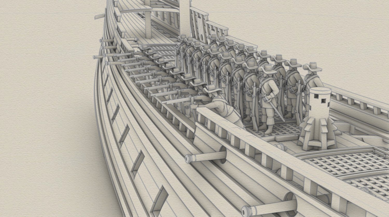
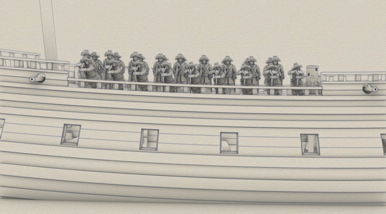
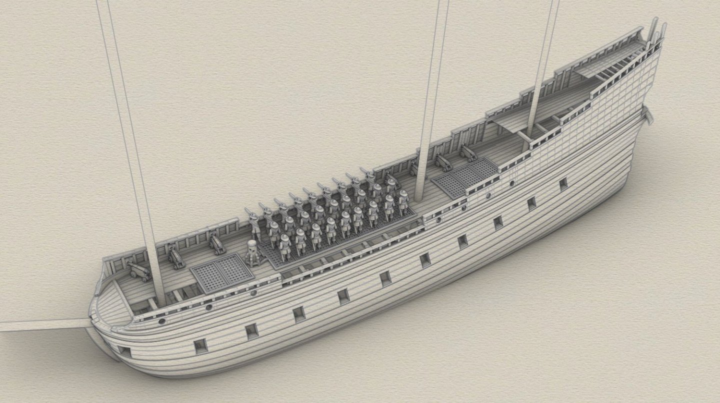
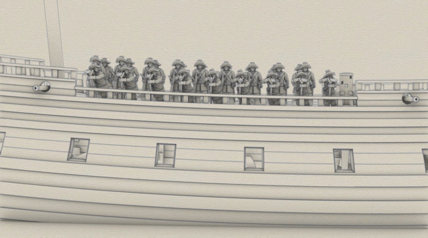
Could not resist placing some infantrymen in the ship's waist. Out of the company totalling 100 men, borrowed from the army for this ship just before the imminent battle, only 27 musketeers are shown here. Some of them, able to throw grenades, were sent to the fighting tops. The sailing part of the crew consisted of additional 50 men. It is difficult to imagine the crowding on board during the battle... Figurines by Captain_Ahab_62 (Thingiverse)

- 257 replies
-
- 10
-
-
-
Both lovely and funny project. 🙂 May I ask what flags do you intend to hoist on your model?
-
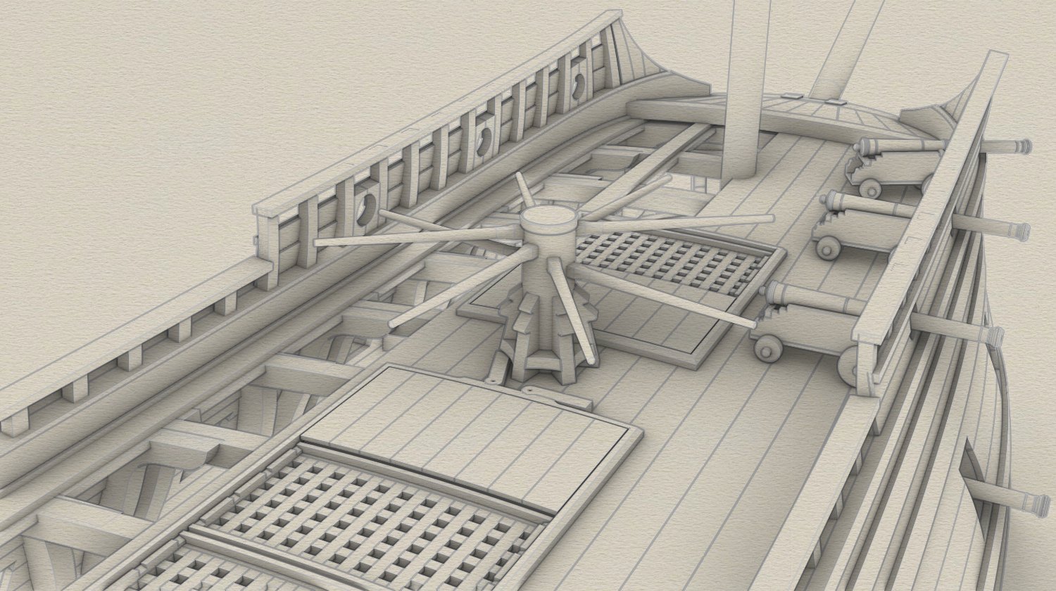
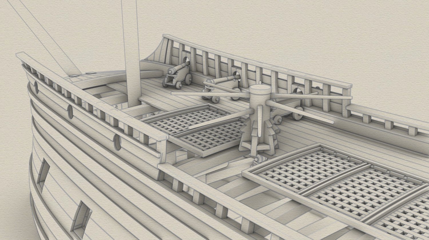
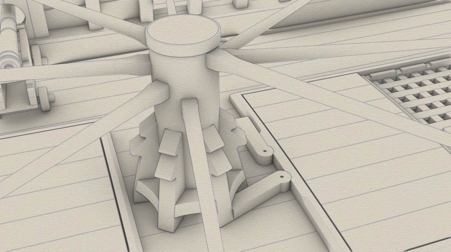
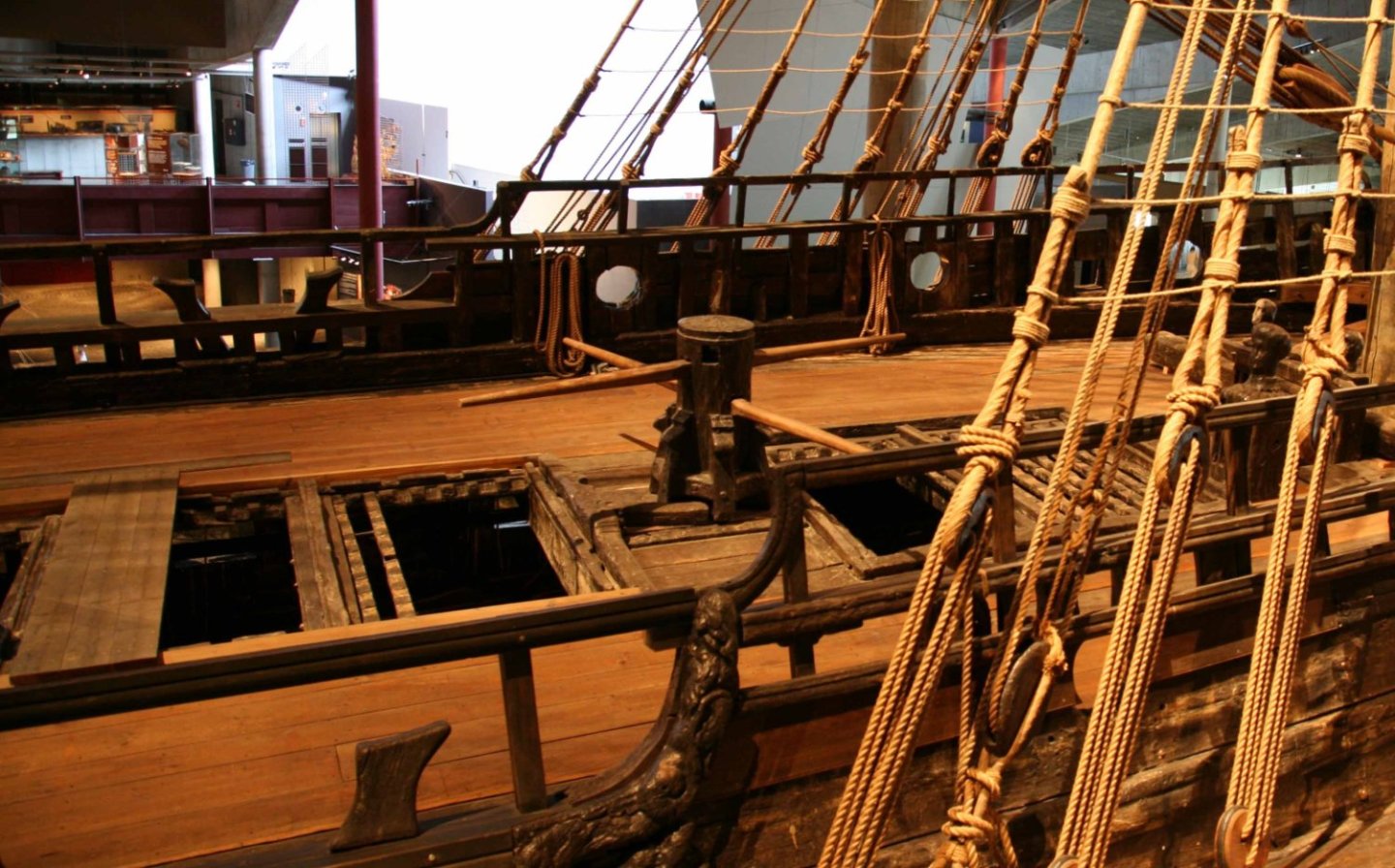
Many thanks for the likes, stimulating... General construction of the jeer capstan completed – spindle lowered by an inch or two and made to the gun deck (not shown here), pawls added, bars reversed, chamfering of the coamings redone. Below a picture of the real thing for comparison (by H. Sasso).


- 257 replies
-
- 11
-
-
-
Working on capstan...

-
Beauty! And even more so as the structural parts are visible.... I love it. As I recall, this boat was given to Tsar Peter by the Dutch authorities, so I imagine it could rightly be considered a fairly typical large Dutch-style boat.
-
Perfect job – extraordinary sense of shapes and proportions of humans and beasts.
-
Ship models featuring visible structural elements have always been my favourites. A pleasure to see yours.
- 55 replies
-
- 1
-
-
- Nordlandsbaaden
- Billing Boats
- (and 1 more)
-
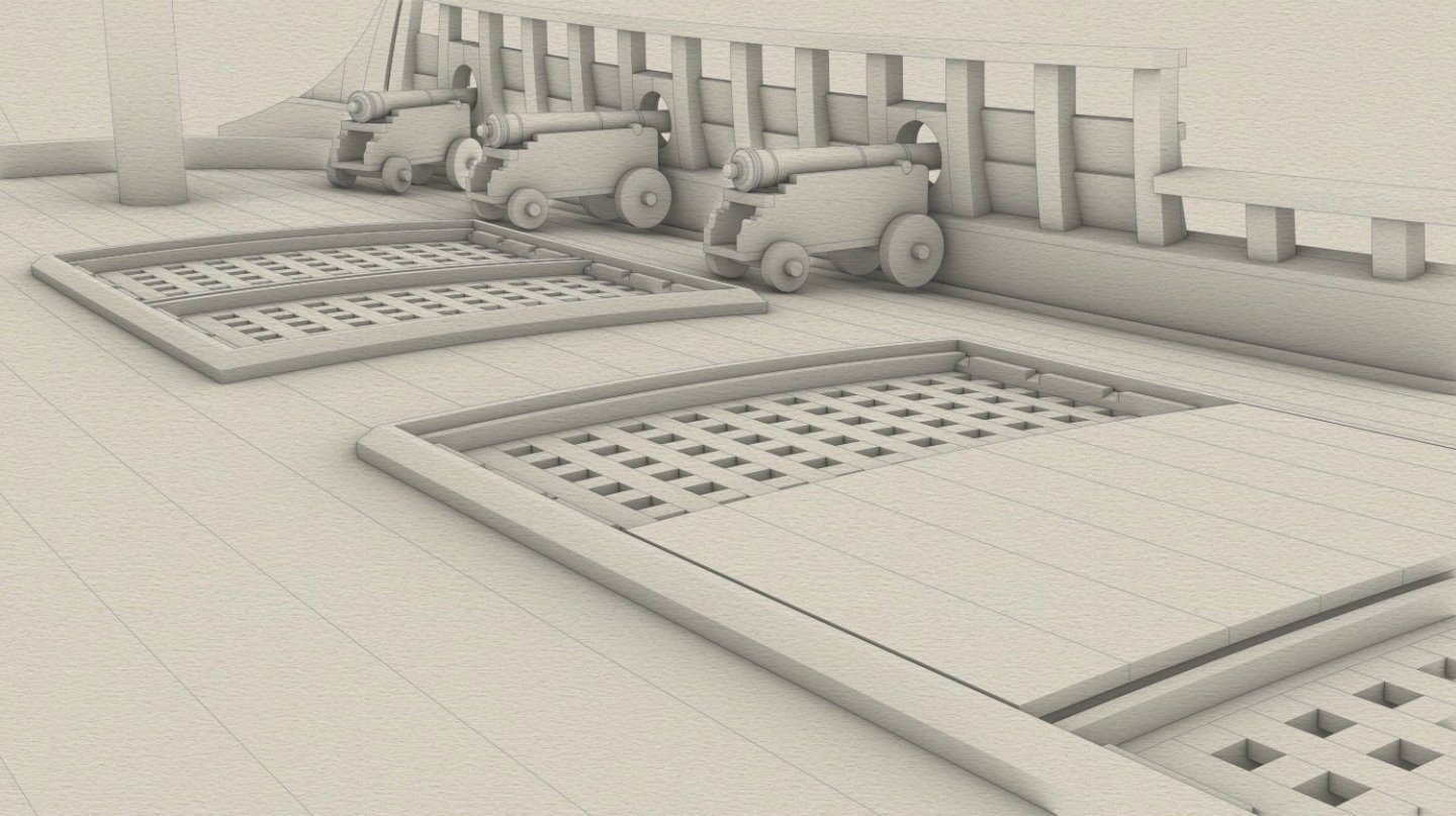
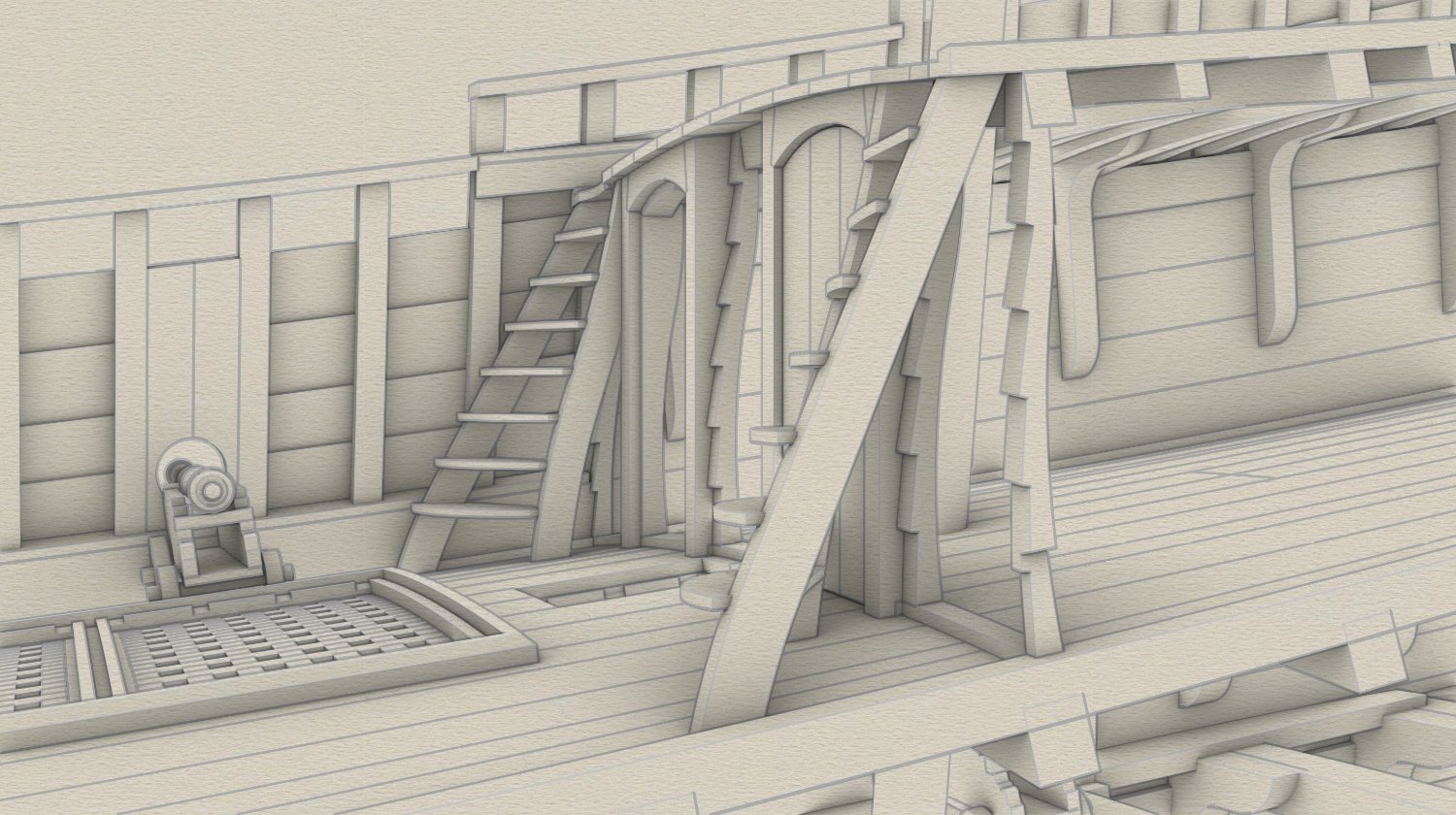
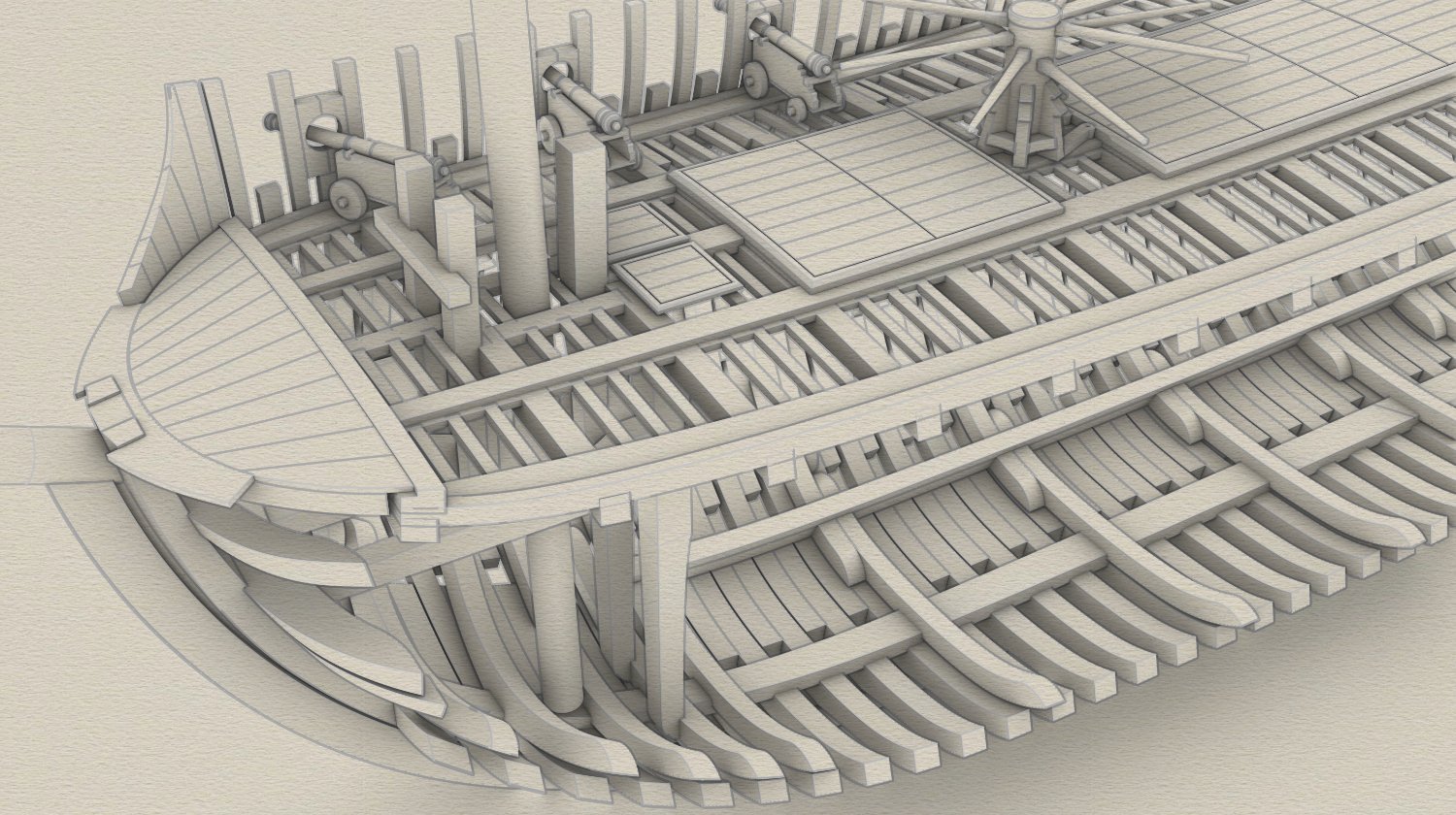
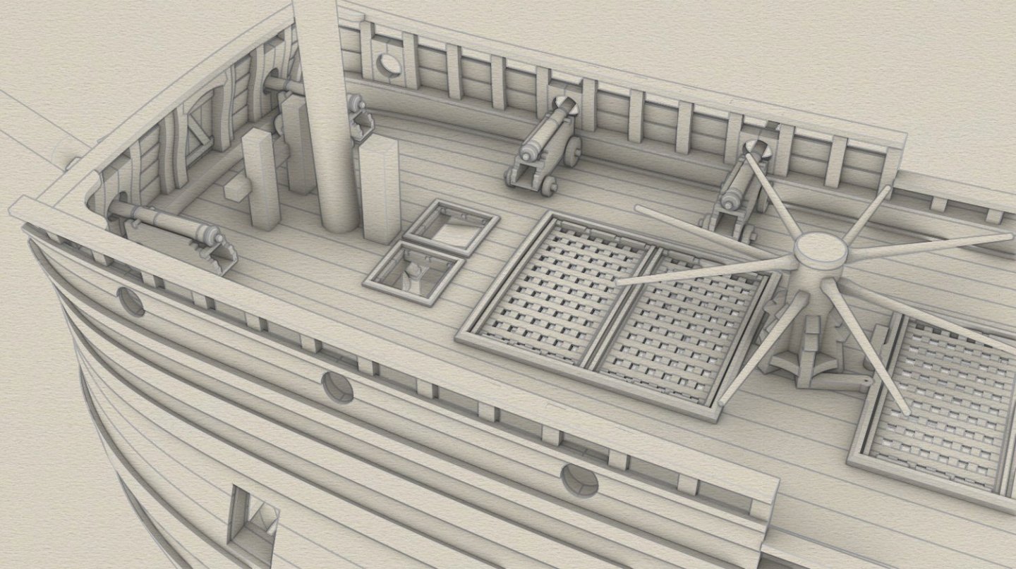
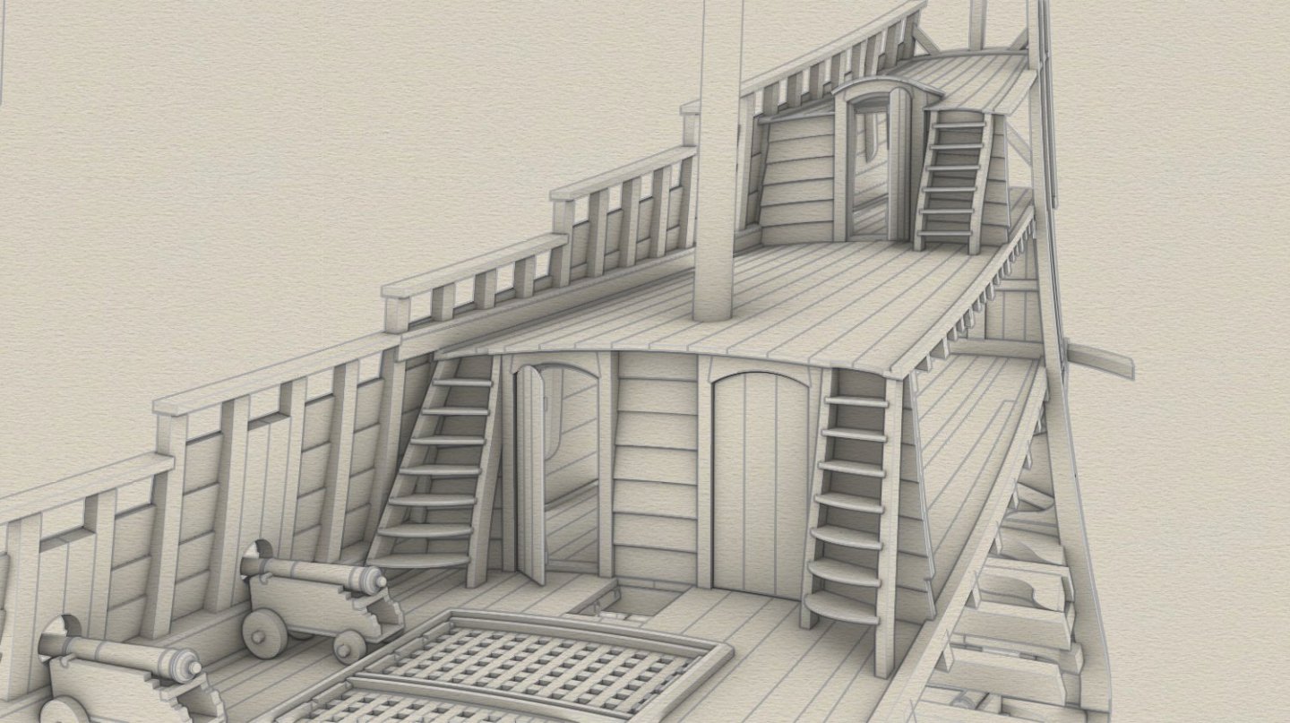
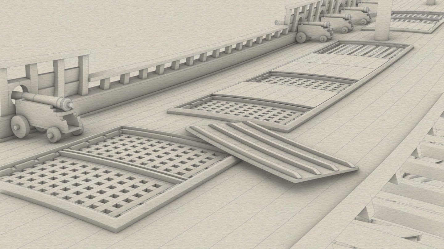
... even more gratings, with one of the hatch covers upside down. Perhaps this appearance of the deck, featuring some of the hatch covers in place and some not, is somehow related to the etymology of the name of this deck, namely 'koebrug' (a Dutch term, in English 'cow-bridge'), where the hatch covers visually act as 'bridges'.
-
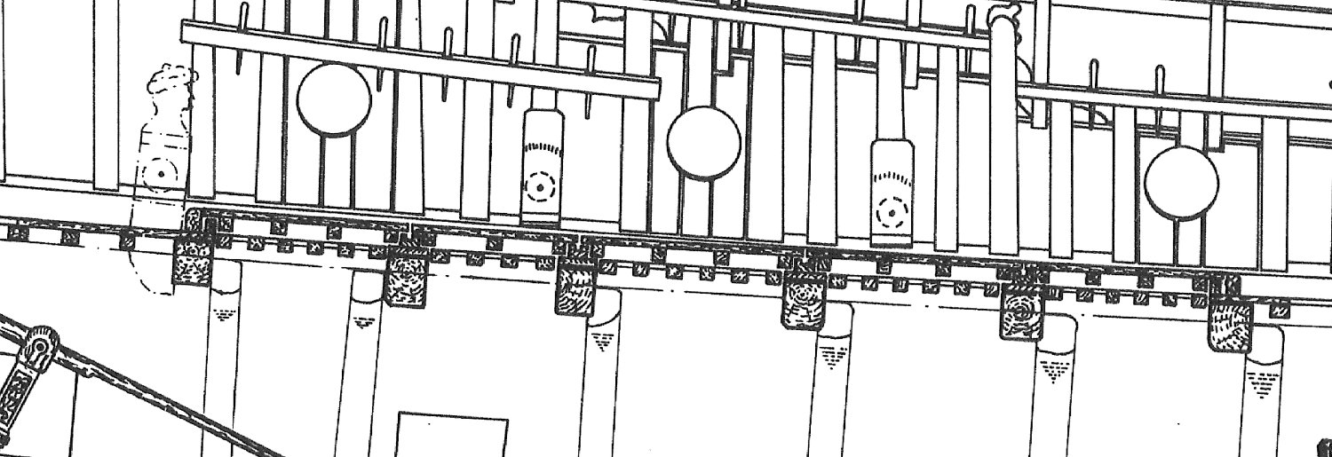
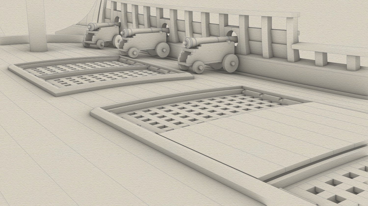
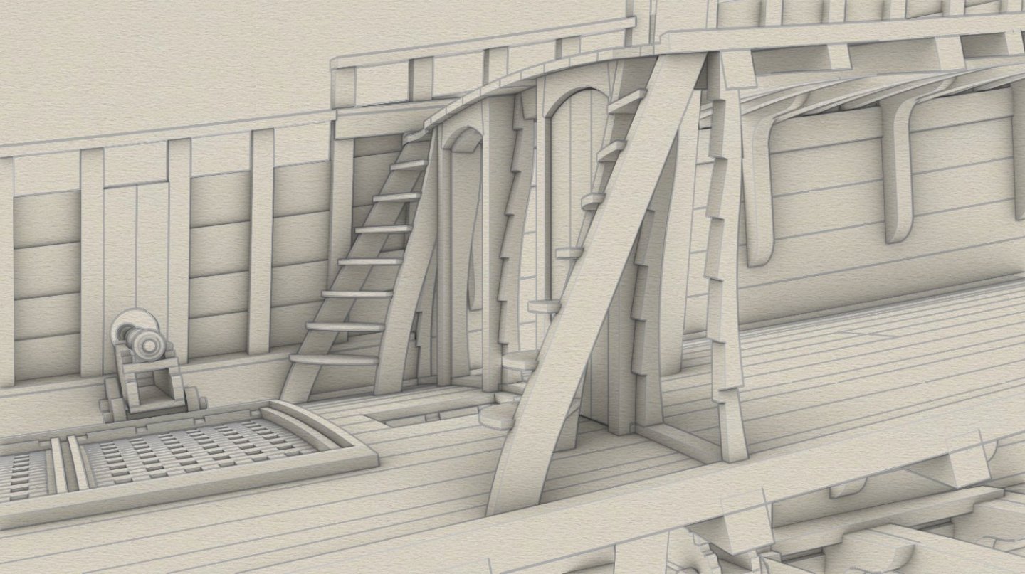
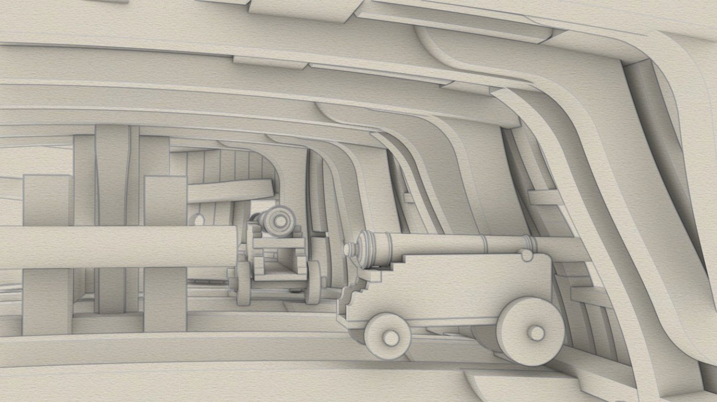
Thank you very much for your comment Mark. I completely agree with you that such coamings could be a serious trip hazard. They are modelled exactly on the "Vasa" coamings, just as many other parts in this reconstruction. Still, this very issue you have raised made me think of the necessity of chamfering their edges (see the updated image below). To be honest, I was more expecting a comment on cannons so close to the rather high coamings, and my explanation would be that these were then the last days of firing on the non-recoil principle and the outboard loading, both closely related to the doctrine and practice of the boarding tactics (as opposed to soon to be widely adopted artillery tactics). Section of the „Vasa” coamings: Updated coamings (much better, thanks again Mark):