HOLIDAY DONATION DRIVE - SUPPORT MSW - DO YOUR PART TO KEEP THIS GREAT FORUM GOING! (Only 13 donations so far - C'mon guys!)
×

.jpg.6c90d67e7e9071af590f4d4a2a8bc908.jpg)
Waldemar
-
Posts
987 -
Joined
Content Type
Profiles
Forums
Gallery
Events
Everything posted by Waldemar
-
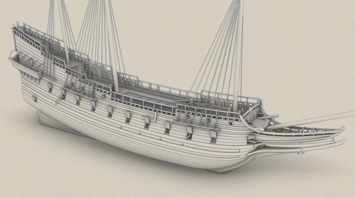
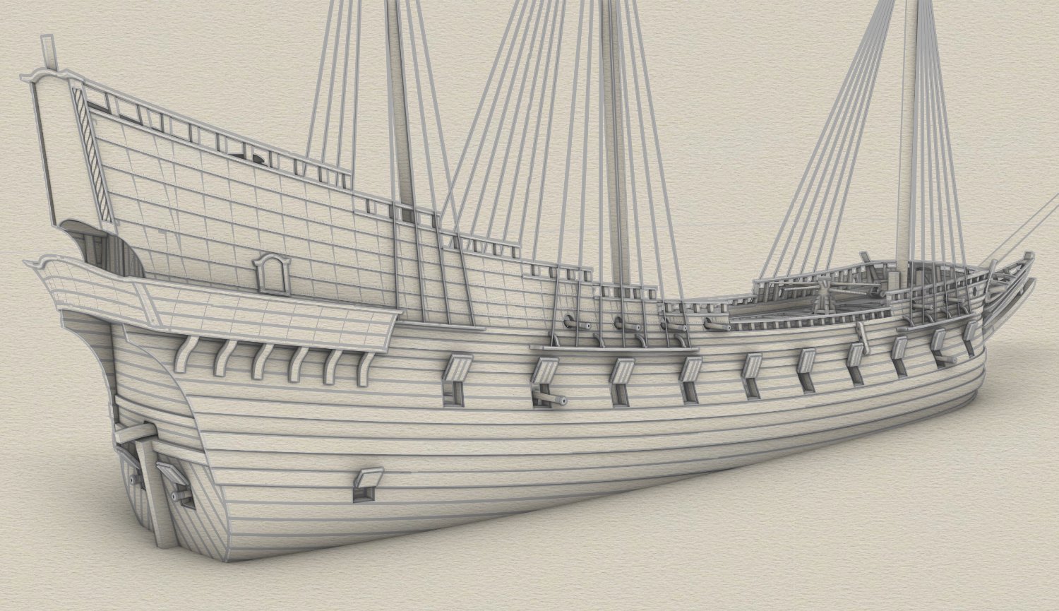
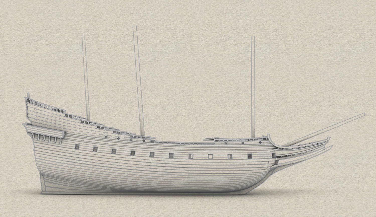
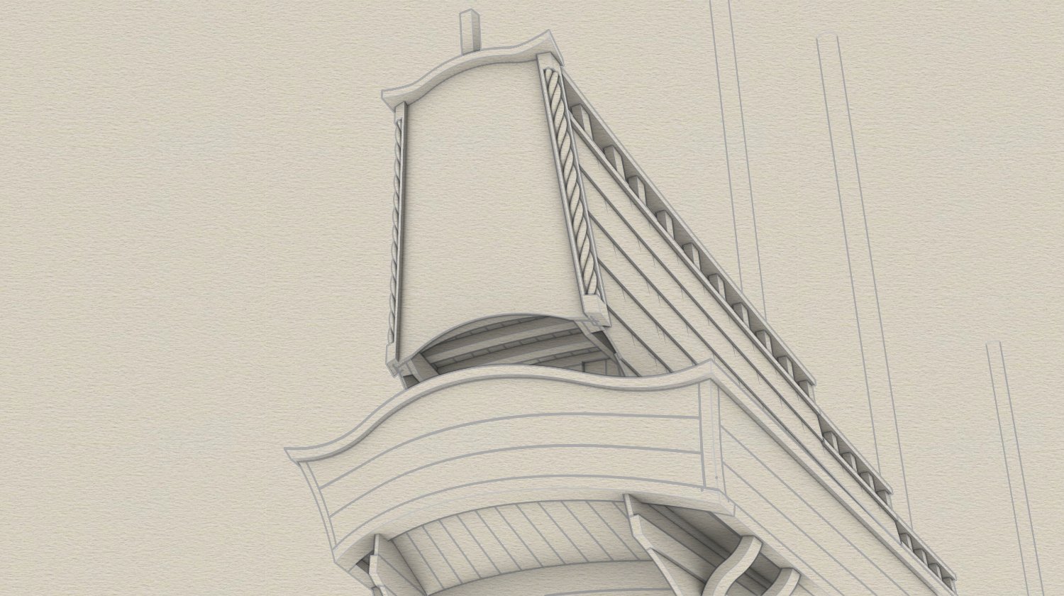
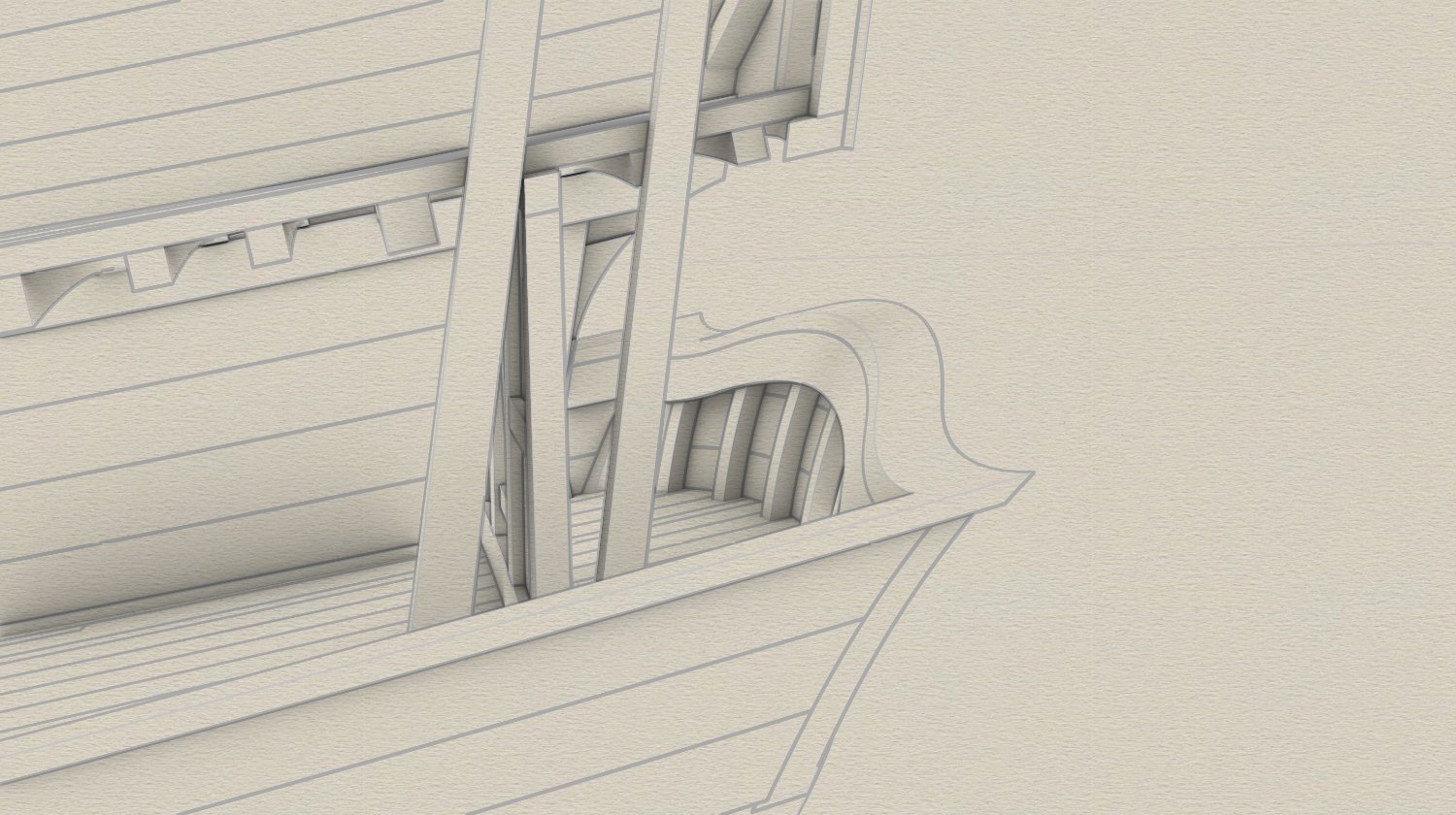
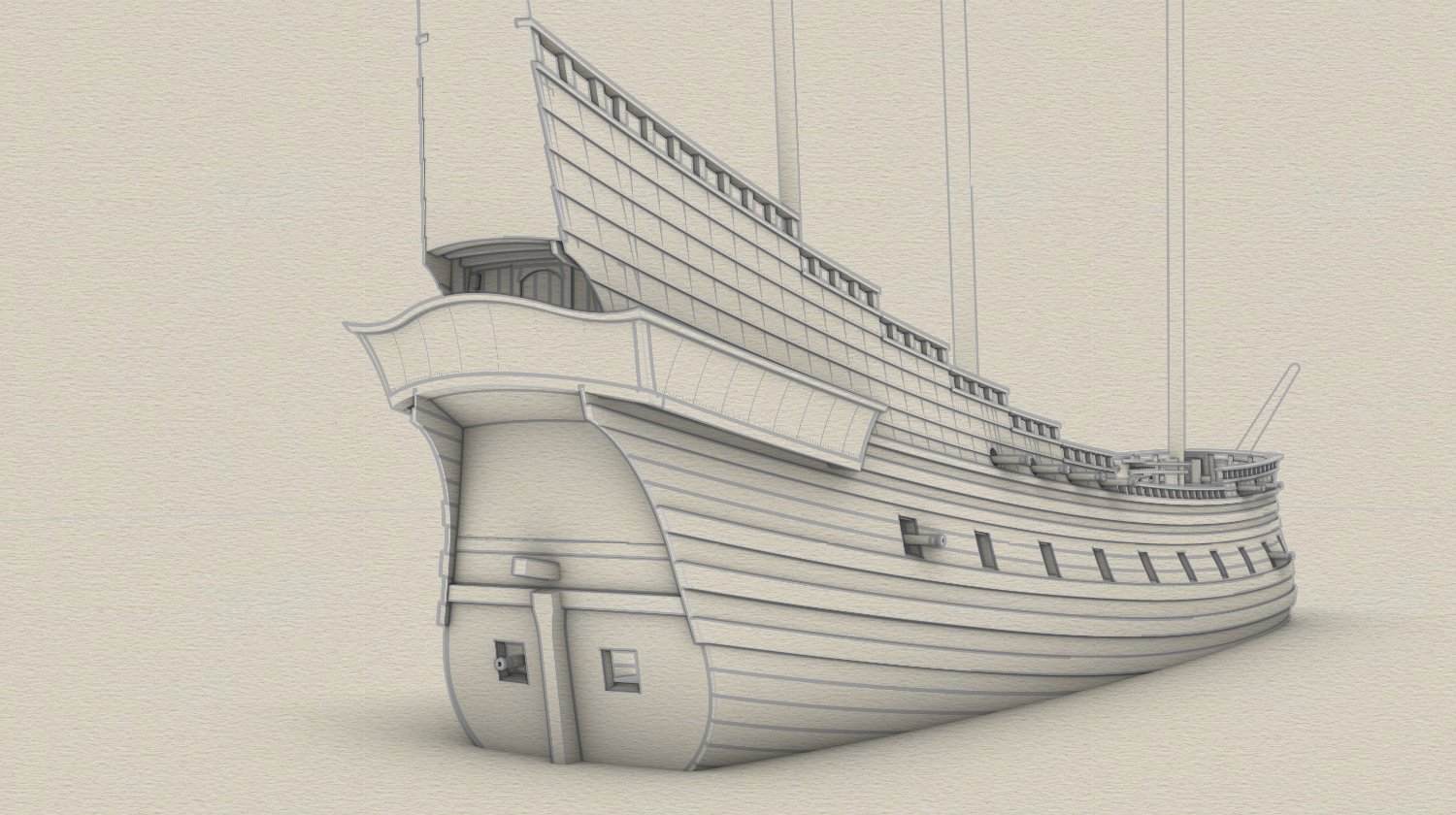
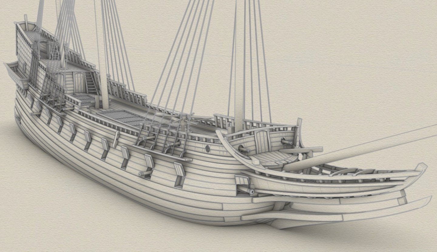
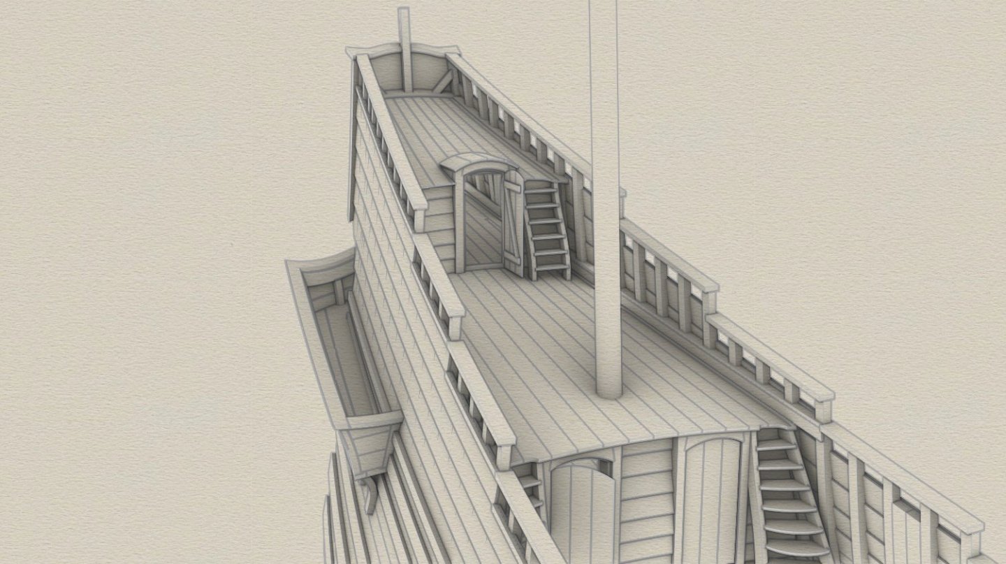
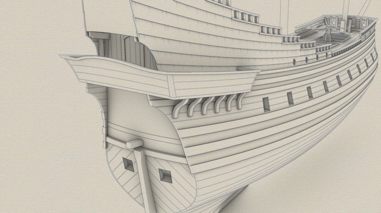
.thumb.jpg.c6343966b029e7941df5b987d129aac6.jpg) Finished, hopefully, external details of the hull not related to rigging: scuppers and less important but conspicuous details – gun port wreaths, balcony ribs, etc. More and more I think of it as a ship of a new just emerging class – the frigate.
Finished, hopefully, external details of the hull not related to rigging: scuppers and less important but conspicuous details – gun port wreaths, balcony ribs, etc. More and more I think of it as a ship of a new just emerging class – the frigate.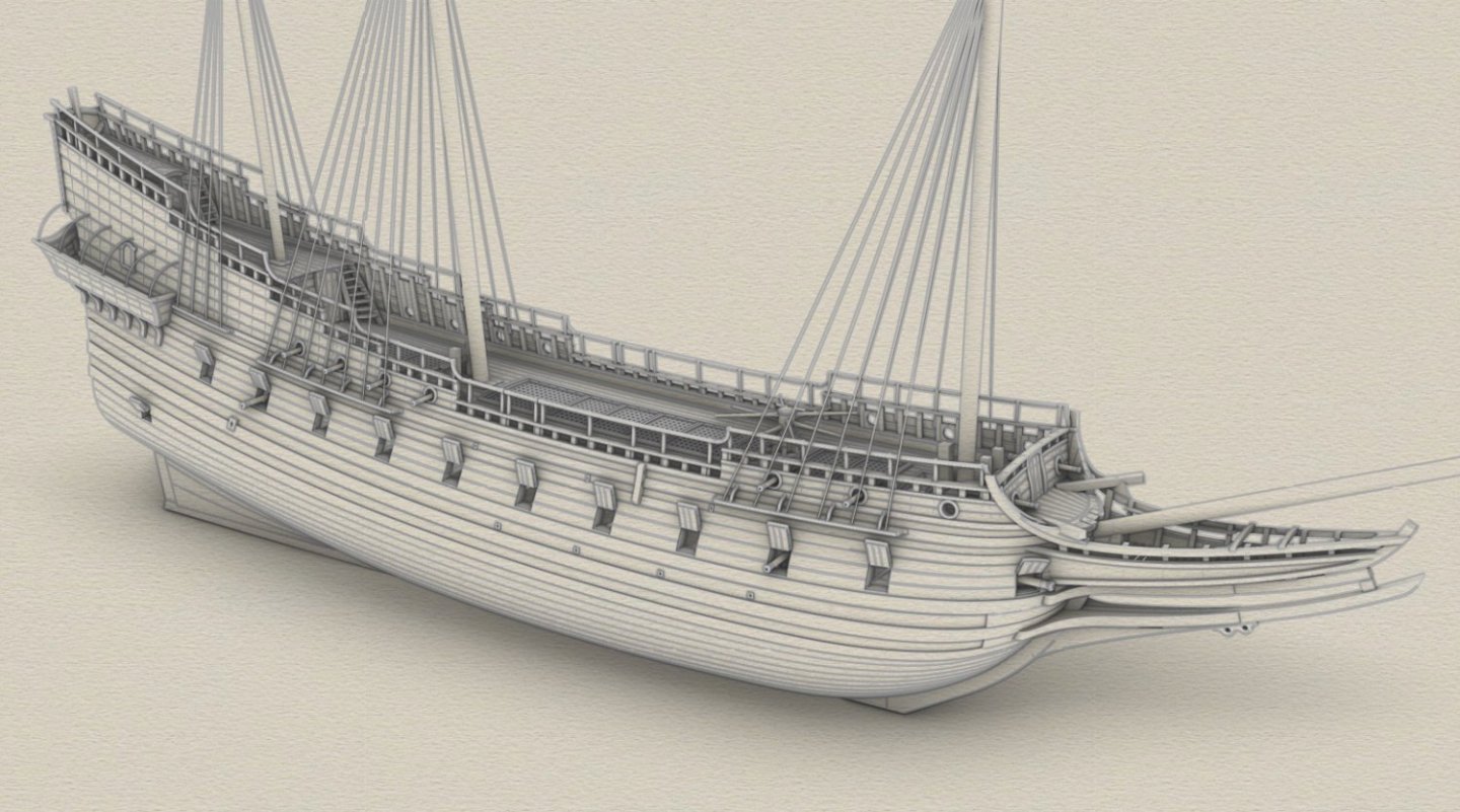

- 257 replies
-
- 16
-

-

-
A neat, tidy job. At least in the pictures... 🙂
-
It's not over yet, is it? And where are the oars, rudder, outriggers, platforms and ornaments, maybe even the crew like in ancient Egyptian tomb boats?
-
... forgot to mention both realistic and attractive shapes.
- 55 replies
-
- 1
-
-
- Nordlandsbaaden
- Billing Boats
- (and 1 more)
-
A lovely finish, natural, 'everlasting' materials (if properly cared for) and a visible structure. This is my favourite way 🙂.
- 55 replies
-
- 1
-
-
- Nordlandsbaaden
- Billing Boats
- (and 1 more)
-
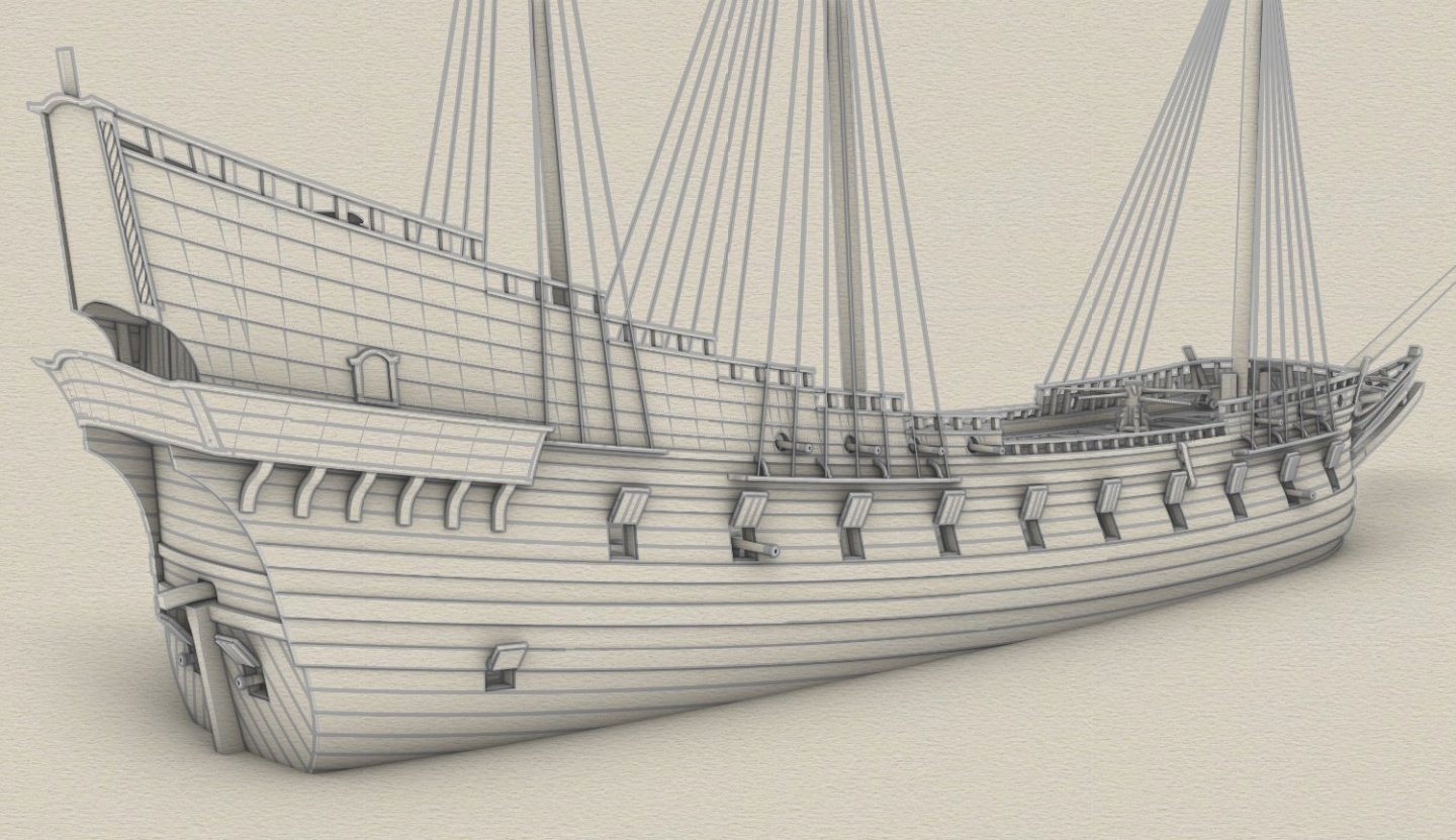
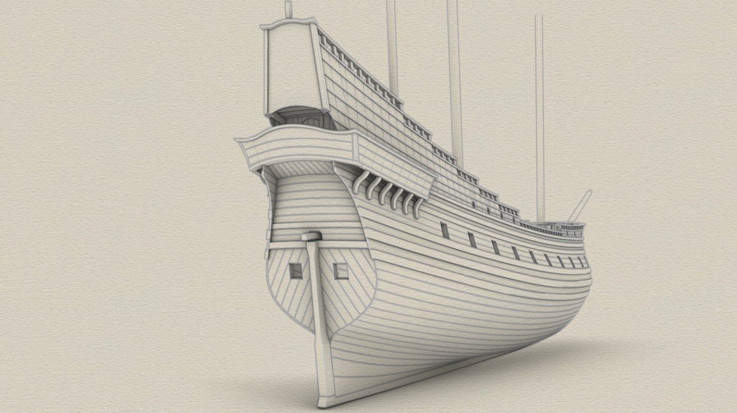
Many thanks guys for the likes and comments... In the quest for speed and weatherliness, the ship was designed with extremely narrow proportions for a warship. The length-to-width ratio is as high as 4,62:1. If highly built with extensive upperworks or multiple decks, she could have capsized, as happened to the 'Vasa' for precisely this reason. Fortunately, the king did not interfere with the ship's design in this case.
- 257 replies
-
- 12
-
-
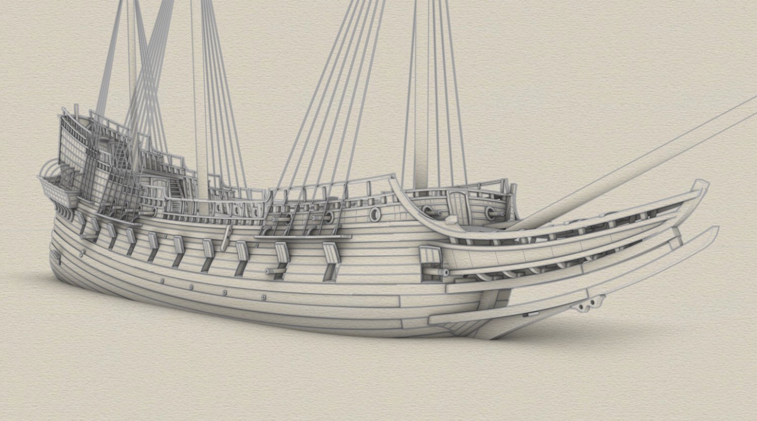
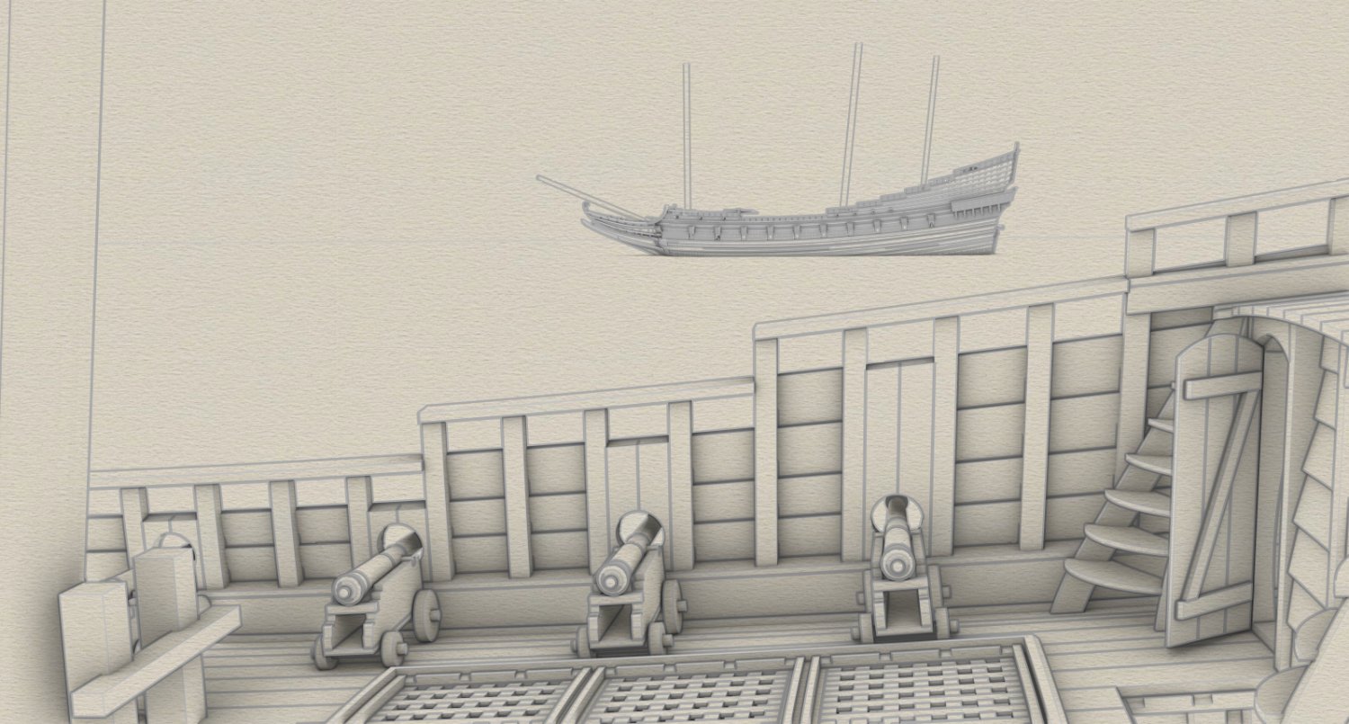
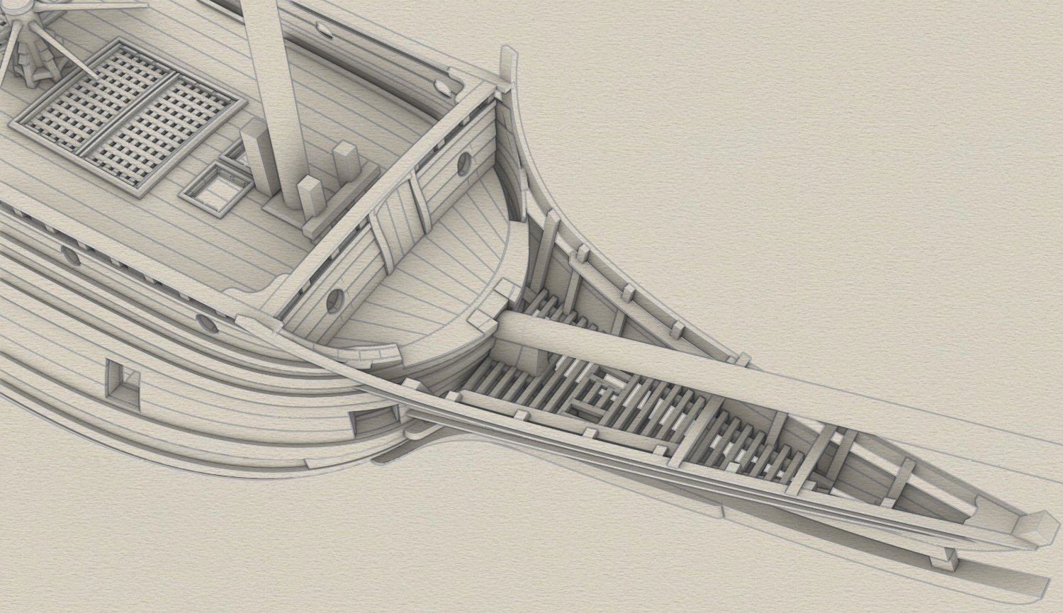
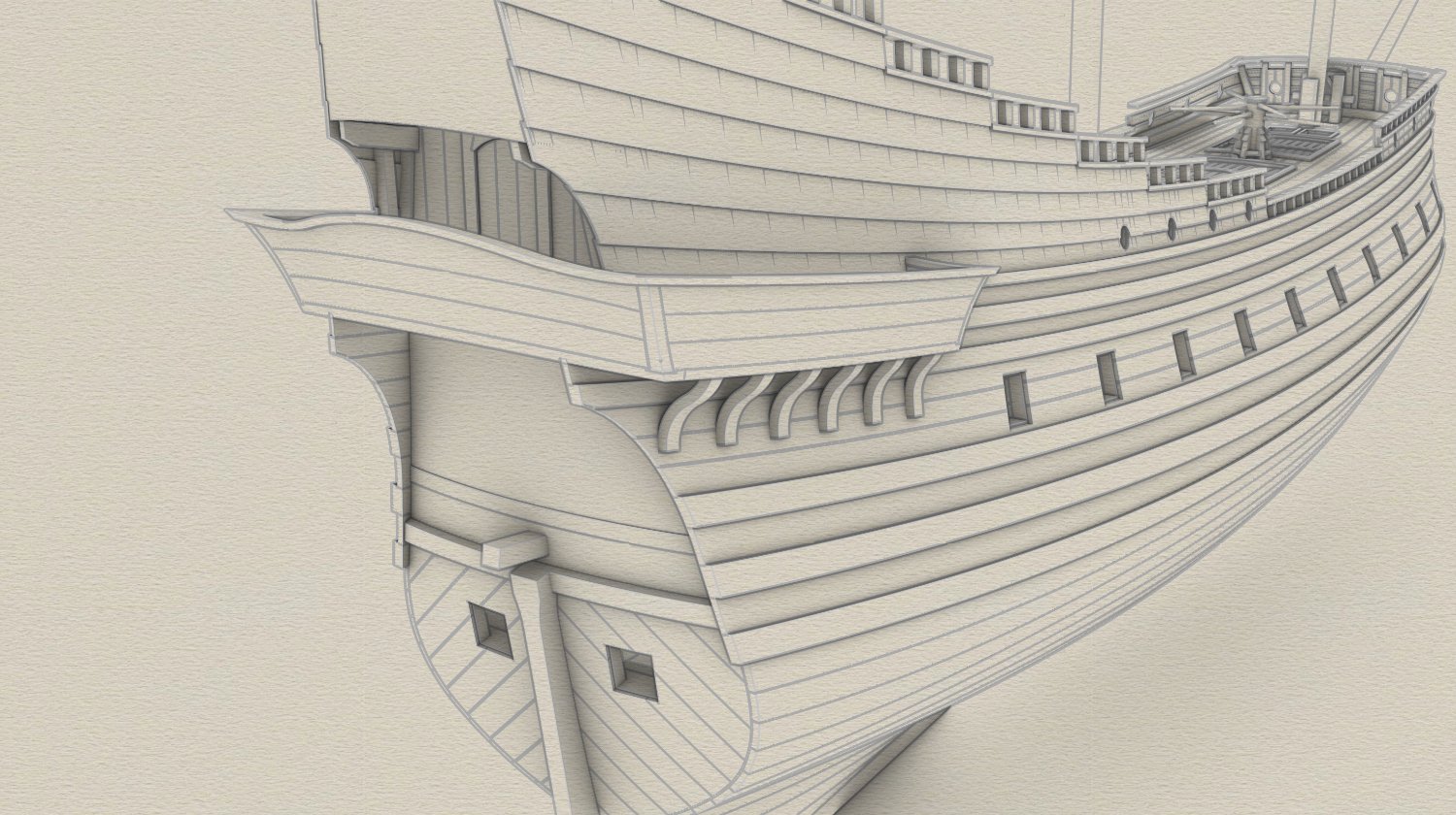
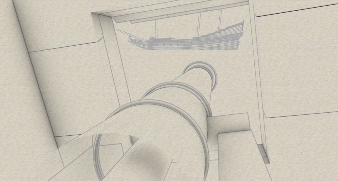
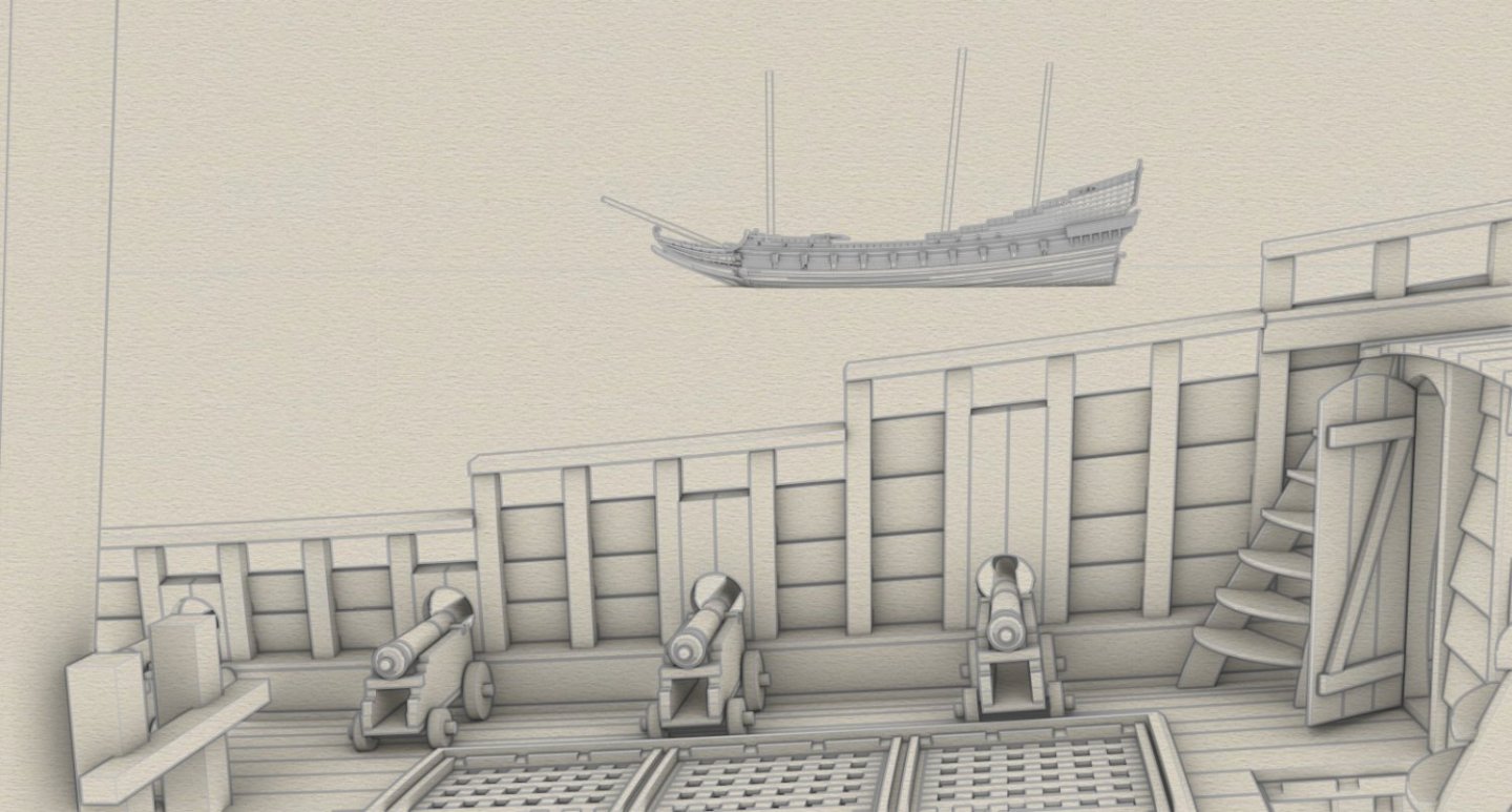
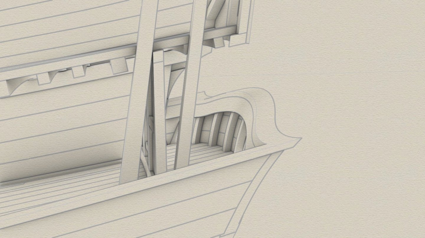
More details have been added: catheads with its supports, gun port lids, chesstree, window and cargo port aft, channels. First-person view of roughly maximum effective range of artillery fire:
- 257 replies
-
- 14
-
-
-

-
Wonderful to see a vessel from my favourite period. Thanks.
-
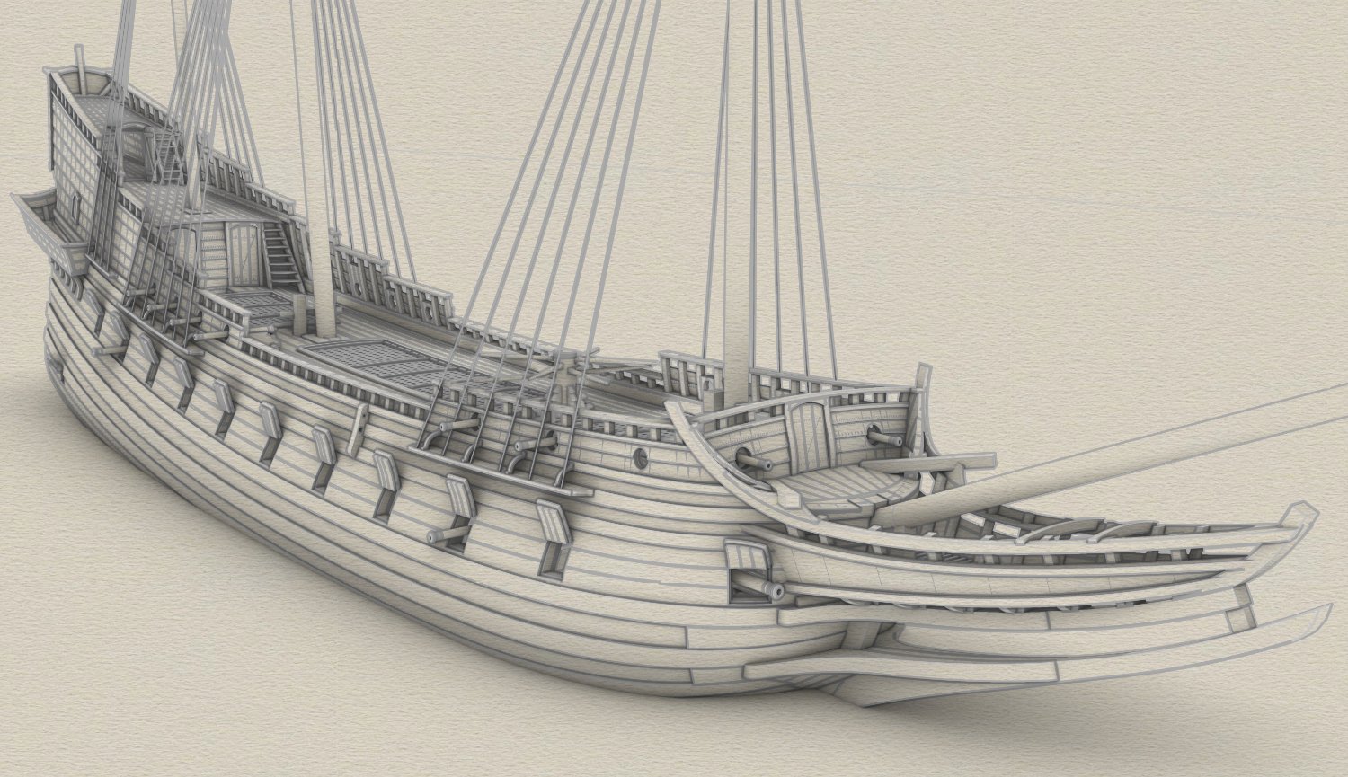
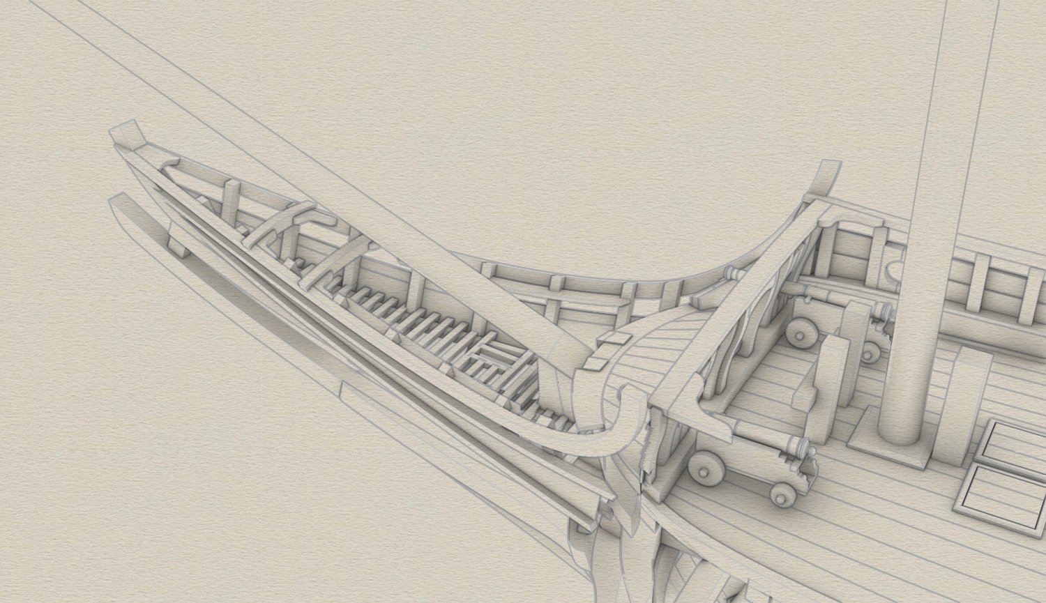
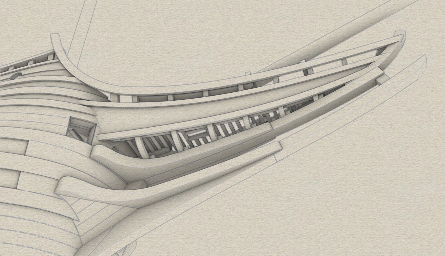
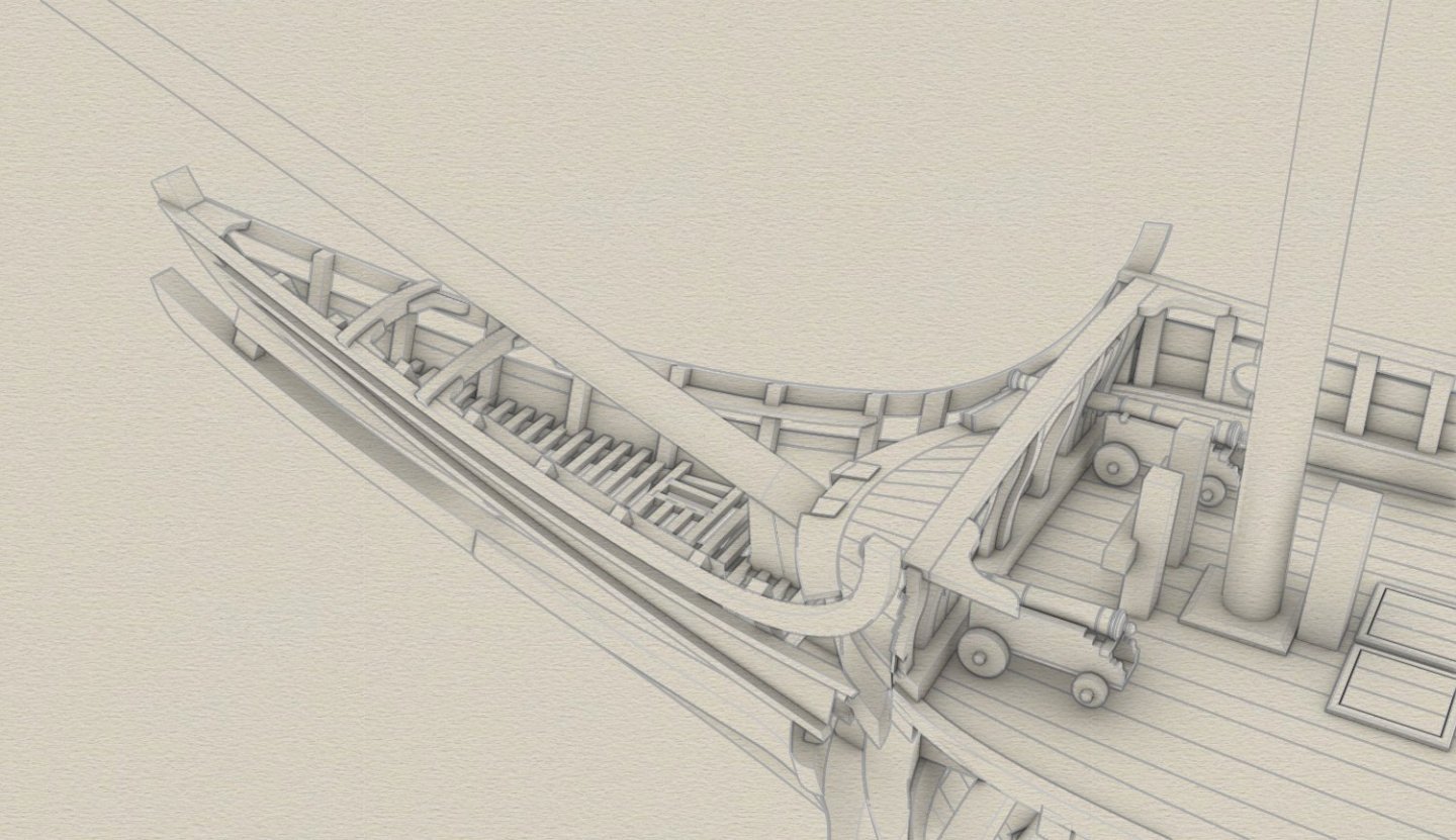
With the exception of the lion and perhaps a few other fellows, the beakhead can be considered finished.
- 257 replies
-
- 10
-
-
-
In those days, only a few ships could match the 'Vasa' in terms of the number of carvings, such as the Danish 'Tre Kroner', the English 'Prince' and 'Sovereign of the Seas' or the French 'La Couronne'. These were all exceptional ships built for show. All the rest, the workhorses of the fleet, were much more modest in this respect. And this ship is such a workhorse for day-to-day duties. There are quite a few shipwrecks relevant to this project. Many of them are well known, except perhaps the Swedish 'Solen', a ship that was sunk in the same battle in which the 'Saint George' participated. Lots of extremely useful material from this site. We still hope to find the remains of the "Saint George" in the river.
-
Thank you very much Scrubby. Well, yes and no. Only scanty data on the actual ship survives (but happily more on other ships of the fleet). There is, however, abundant material when it comes to background information. Archaeological, iconographic and written sources were used for this reconstruction: Venetian, Portuguese, Spanish, French, Dutch, English, Danish and Swedish. All of these proved useful. As a result, the ship can be considered a more or less typical man-of-war of the Baltic area.
-
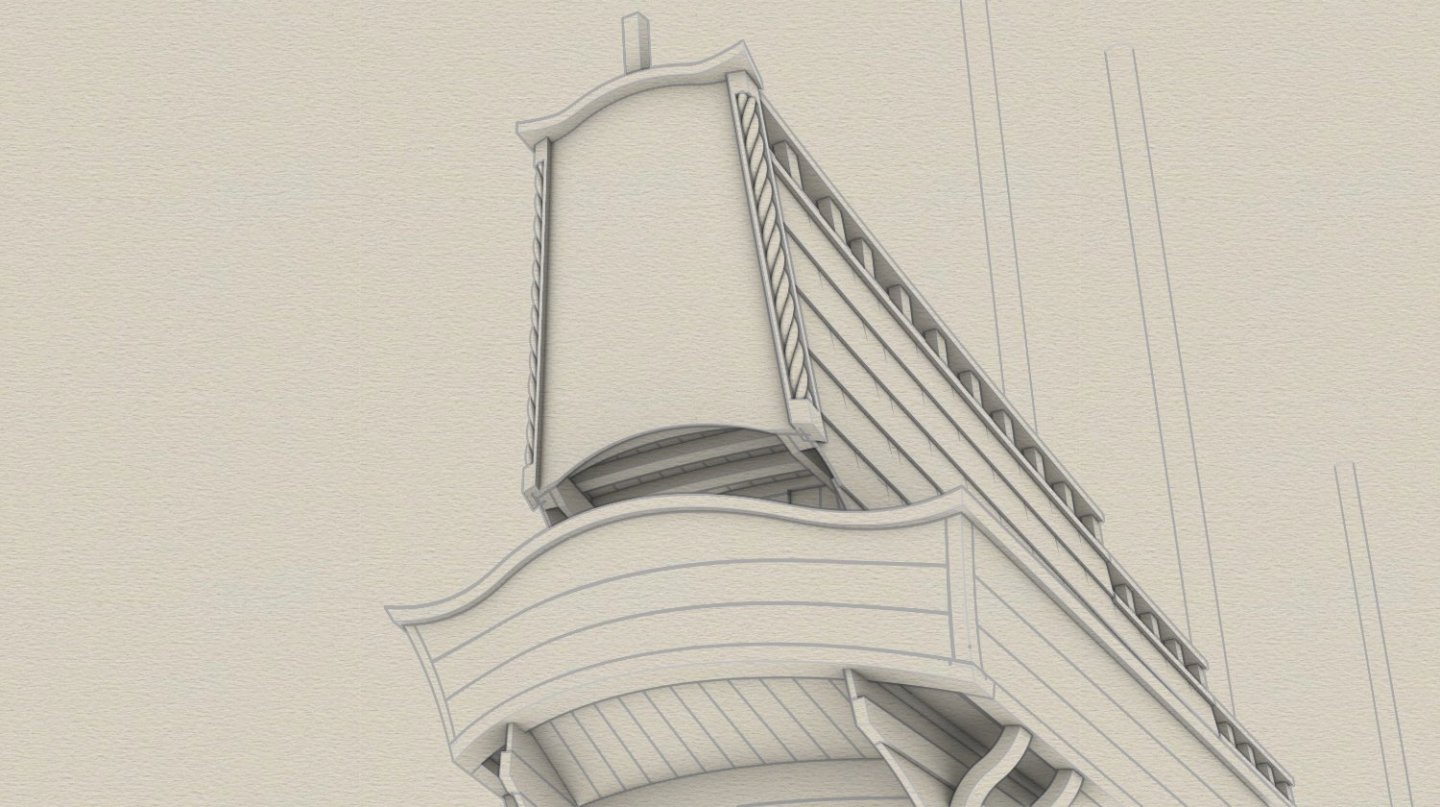
Ye dredded reer ormanents stryke yette agayn (making forum server down for two days). In the meantime... ... the final lines of the stern taking shape. I have modified the internal structure slightly (not shown here) in order to lay a row of planks under balcony lengthwise rather than across as was originally intended.
- 257 replies
-
- 12
-
-
-
Thank you, Druxey. So the matter is finally settled by the two top experts showing up in this log. A word of appreciation is also due to the artists of the day for their realism.
-
Modellers won't be happy. Each bracket has a different curvature, as - in fact - all parts of the balcony do.
- 257 replies
-
- 13
-
-
-
I C O N I C S H I P and incomparable shots! Many thanks for this. I think I saw Fred Hocker too, top expert on this vessel and period shipbuilding generally.
- 1 reply
-
- 2
-
-
Time for the stern gallery. In progress. The iconography suggests that only the two largest ships had balconies and other vessels had none.


-
Okay, so I'm waiting for your coming back.
-
In a way I envy such a fast, smoothly running project. Mine has been going for many long months now....
-
A small beauty emerges... I wonder how this little ship would maintain lateral stability afloat....
-
Thank you for this comment Lieste. To make the matter hopefully simpler, I have already prepared a graphic for my soon-to-be-published paper on the fleet's artillery. Shown here are the most typical samples mentioned in both extant inventories. In black are cast- and wrought-iron guns, and in bronze are, of course, bronze guns 🙂. All drawings are based on real surviving artillery pieces. Most interesting are surely assault/hail-shot type guns. They could be large or small, carriage or swivel, bronze or iron (be it cast- or wrought-iron), chambered or not, muzzle- or breech-loaded, conical or cylindrical bored. Larger specimens would be referred to in English as cannon-perriers. As an aside, four large (meaning carriage) Polish bronze assault/hail-shot guns such as depicted below, called at the time „stone guns”, because they used before to shoot stone missiles, were issued to the 'Vasa' in 1628.


-
Thanks. Lovely shapes are what matter...
-
Hello. Maybe little, but promising project and I feel I will like it. What kind of wood have you chosen for the hull?