HOLIDAY DONATION DRIVE - SUPPORT MSW - DO YOUR PART TO KEEP THIS GREAT FORUM GOING!
×

.jpg.6c90d67e7e9071af590f4d4a2a8bc908.jpg)
Waldemar
-
Posts
986 -
Joined
Content Type
Profiles
Forums
Gallery
Events
Everything posted by Waldemar
-
.thumb.jpg.c6343966b029e7941df5b987d129aac6.jpg)
17th century Baltic fluyt wreck found
Waldemar replied to Louie da fly's topic in Nautical/Naval History
To avoid drowning in an overabundance of short publications with repetitive information, I would simply recommend one comprehensive book by Niklas Eriksson, Urbanism under Sail. An archaeology of fluit ships in early modern everyday life, 2014. It can be downloaded from the links/sites provided above by Steven. -
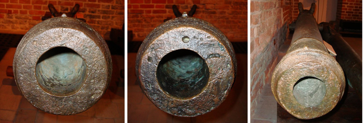
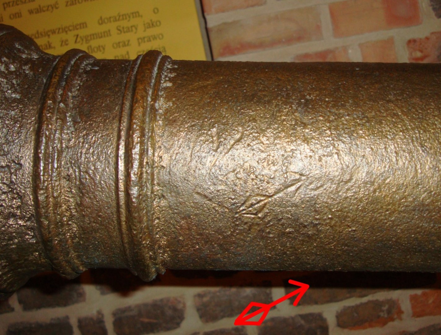
This is the only unrecognized stamp found on the recovered gun tubes of the Swedish origin and in desperation I even imagined the same 🙂. Perhaps someone reading this log has an idea? It is not the equivalent of the English "Broad Arrow" identifying royal property, as a similar mark was found on only one of the other gun barrels from the "Solen" (on a captured bronze Polish 3-pdr, and this stamp was almost certainly made by its Swedish users too; see the image below, side view). Anything can be envisaged, say – an anchor marking a gun intended for the navy use? Runic lettering? Or something of a more personal/individual character?
-
Indeed, and they did their job! For good or for bad, depending on the side 🙂.
-
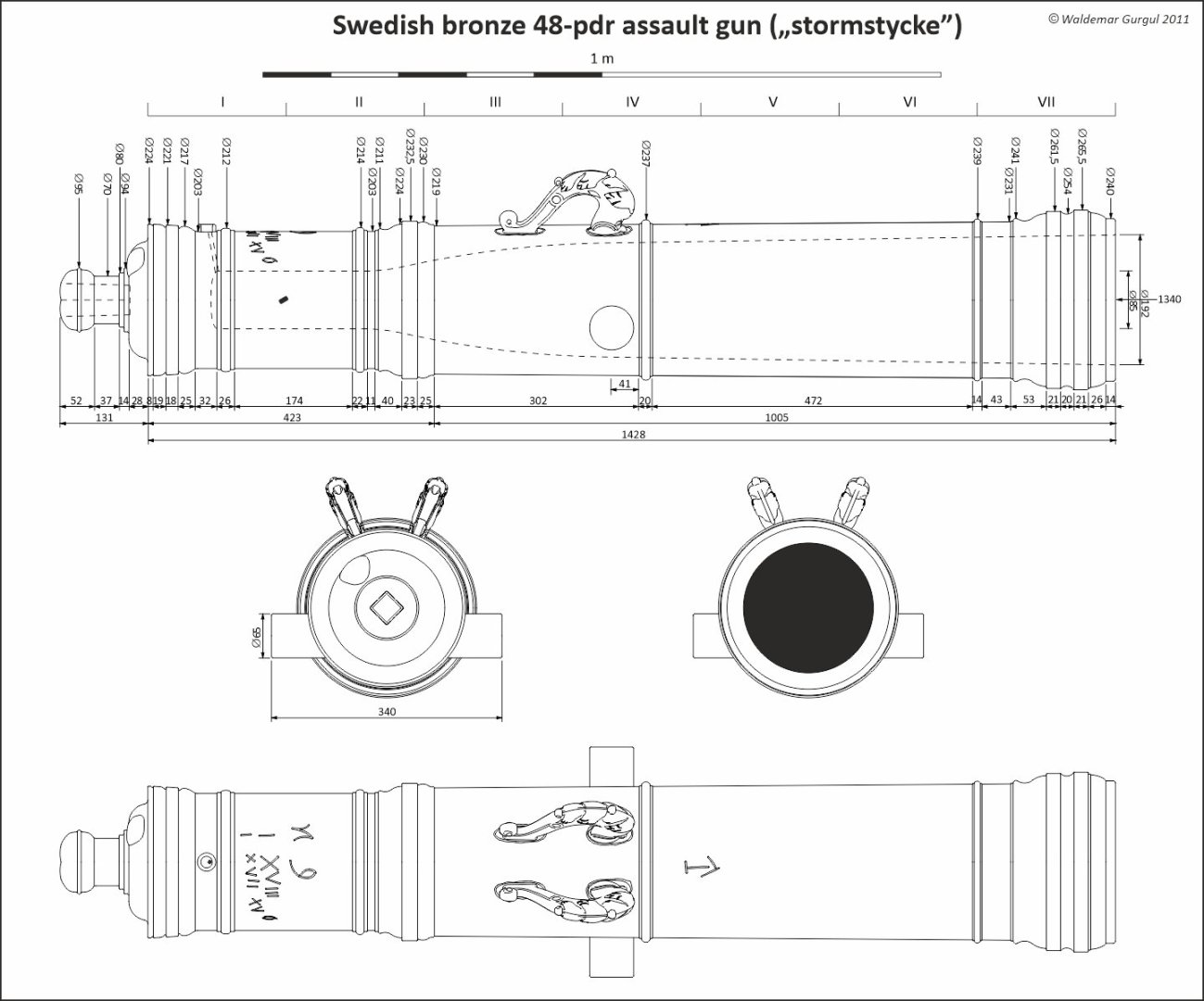
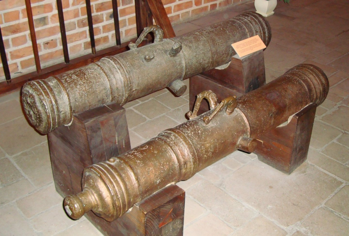
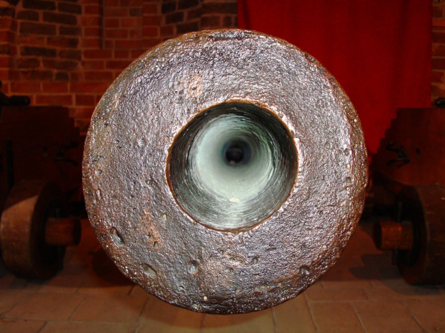
As an alternative to the above Polish gun barrels, captured Swedish 48-pdr assault guns can be substituted. 15, 6 and 6 pieces were cast in 1621, 1622 and 1624, respectively, at the Stockholm foundry. They were used both by the land forces and the navy. Note its slightly conical bore. ... and the real thing from the „Solen”:
-
... To begin with, two assault guns (referred to in English as "cannon-periers," in Swedish as "stormstycken," and in German as "Feuerkatzen" – "fire cats" or simply as "Schrotstücke" – "hail-shot pieces"). They were most likely placed behind the mainmast, as on the "Solen". According to the 1565 inventory of one of the royal arsenals, six of these "small stone guns" in the weight range of 8.5–9.25 centners, belonged organizationally to the field army. They may also be of interest to the "Vasa" modellers, as three such trophy guns were issued to this Swedish ship in 1628.

-
Concluding on the issue of defective, irregularly cast cannons and their (in)accuracy: in some artillery manuals of the 16/17th centuries one can find corrective methods (by mathematical means) of aiming such cannons. These, however, are of doubtful practical value even in static warfare on stable land. And their use in dynamic naval fight was completely out of the question due to the constantly changing range, and the inevitable fact of firing from a moving, unleveled and swaying platform at an equally moving target in an unpredictable location/direction. Finally, due to the sheer illiteracy of most or many early modern period gunners. Experience (if any) and luck may have helped, but only to a certain extent. These are my assumptions for this project and this very period in general, regardless of what more or less scholarly 18/19/20th century works on artillery say. I will also prefer to keep in mind contemporary (meaning 16/17th century) tactical instructions and descriptions of actual encounters. Now preparing mentally to return to drawing work....
-
Extraordinary workmanship of the legendary Mediterranean predator vessel. What a light structure!
-
That's right. This small triangle is to avoid a heavy and damaging splash against the waves while pitching. Good, interesting work.
-
Finally some free time to look around.... It's just not right that such works of art are created only for the ships of a few major sea nations 🙂. And out of sheer jealousy, I decided to create plans to enable the construction of a similar jewel 🙂. I love structural models.
-
A sort of déjà-vu... I mean a book packed with equally beautiful and realistic images (and plans!) – 17th century Dutch Merchant Ships. Wonders!
-
Great photos, great music. Professional level. BTW, thanks again for sharing recently your best up to date pictures of the Vasa.
-
Lieste, all that is fine, but what do you exactly suggest in terms of specific solutions for this project?
-
Lieste, all that you have written is very good, but for an era of artillery tactics with an already advanced firing techniques and much better quality guns. But even in the Vauban era and later, on stable ground in siege work by scientist gunners, do you know how close the heavy siege guns had to be positioned to the walls in order to gain accuracy needed to effectively make the breach? Not more than a few tens of meters. Another example from the period close to this project: after several days of bombarding the Invincible Armada from hundreds of guns and expending all available ammunition, the English fleet accomplished almost nothing in terms of the Spanish ships destruction. Ricochet fire, if used intentionally then at all by English gunners, must have been to no avail as well. So, for the needs of this very project, I would prefer to think in terms of the early 17th century practice/reality than 18th century theory. Druxey: I should have added that some primitive form of elevating/depressing is possible by shifting barrel rests to different positions. This would be required to fulfil the standing order from the so-called Fleming Instruction of 1628 (Swedish admiral). From memory: "if boarding is not possible, the ships should stay close to the enemy ships and aim at their waterline". No ricochet fire is mentioned in this Instruction. One could also imagine additional wedges between the barrel rests and the gun tubes themselves, but their usefulness would be rather poor due to the rocking of the ship.
-
No Druxey, it was no needed. Artillery fire was usually opened at the point blank range or even less, otherwise it was waste of ammunition or missing the only chance to effectively bombard the opponent. Look at the muzzles of guns from the "Solen". In many of the pieces the bores are so much out of centre, that even at the musket range on land they could easily miss the target. Ironically, a number of these pieces are cast with foresights, equally out of place. Therefore, the small notches were cut by the gunners for attaching the aiming reeds (visible on the left barrel). There are much more geometrical faults in these guns, rendering them suitable only for the closest range fire.

-
Daniel, very nice work and it looks very promising. This is why I have to say (in simple soldiery words, forgive me) that you have to follow Patrick suggestion to fill the bow part with wooden blocks until too late, in order to avoid unsightly bent on the first frame. Then you may make it pleasantly smooth, even by eye. You may hate it now, but later you would not be able to correct this unevenness. By the way, this is my most favourite shipbuilding period 🙂. Cheers
-
Many thanks Ab. Thanks to the good advice of Fred Hocker I was able to make hopefully reliable graphic reconstructions of all the "Solen" carriages, which I published in 2011 together with their descriptions. Here you have such sample reconstruction of another carriage from the "Solen", shown with its preserved wooden components. Exceptionally, it has only single hook attached to its cheek (and not double one as in all others). Instead, it has a hole at the rear of the bed. Some iron fittings are the same as in other carriages, and some are unique in its arrangement. All parts of all carriages are made of single piece of oak. The same for the trucks (wheels), which were also found in quite large number in spare parts storeroom. The fibres of the larger front trucks are always parallel to the carriage cheeks, while those of the smaller rear trucks are always perpendicular to it. Front trucks could have chamfered edges, as shown in the picture above. I think double layer trucks are only later development, as they are single in many other preserved carriages from this period too.

-
Many thanks Scrubby! It gives power to go on... Mark, you are absolutely right. Just to start the new topic: As requested by modellers, the ship's armament is treated next. One of the most valuable source materials for this reconstruction are the cannons and carriages from the Swedish warship "Solen" ("Sun"), which fought bravely against the Polish fleet in the battle of 1627, although not against the "St George" herself, and I was able to subject her salvaged armament to detailed analysis many years ago. Out of the ship complete armament of 20 guns, not even two barrels are identical (of Swedish, Ruthenian and Polish origin). As well, not even two carriages are similar in size, shape, decoration and construction, each being individually built to a specific barrel. The general carriage construction is shown below and it is closely based on one of these preserved carriages (English names of its parts are in gray). It was perhaps the same on the "St George", although such wild diversity will be reduced for practical reasons in this reconstruction.
.jpg.4a58603ba097120467669d39a1614f0e.jpg)
-
Just a note to let you know that today my project has been formally accepted by the investor and the two-dimensional drawings handed over to him. The construction of the model in 1:15 scale has also been confirmed. However, this is not the end of this log. Au contraire. Now comes the second stage - designing the 'loose' elements of the ship such as artillery, masting, rigging, etc. Intentions have also been put forward to prepare the ship's drawings for sale and other applications. Still a lot of work to be done, but for the time being I need a little rest from the intense efforts... 🙂
-
My most favourite period. Caravelles, Carracks and Galleons. Great Discoveries and yet relatively uncomplicated ships' construction without Industrial Era sophisticated components. Thanks for this.
-
Jules, you are simply wrong again. Read or re-read my post #1 and #77. I don't believe you Jules, sorry. I have never stated that. Read or re-read my post #1 without manipulating its content. And why do you expect me to do something, and even more so a hard work, especially for you just for free? You kidding, right? Is this your way of doing business? Don't answer. Last but not least, I detest manipulation. Please don't try it again. Thank you in advance, Jules.
-
It was only relatively recently I learned that just such elements, in true scale, and both at the bow and stern (especially the wales and planking in the 'difficult' places), were cut from compass timber rather than bent to shape. Anyway, perfect job.
-
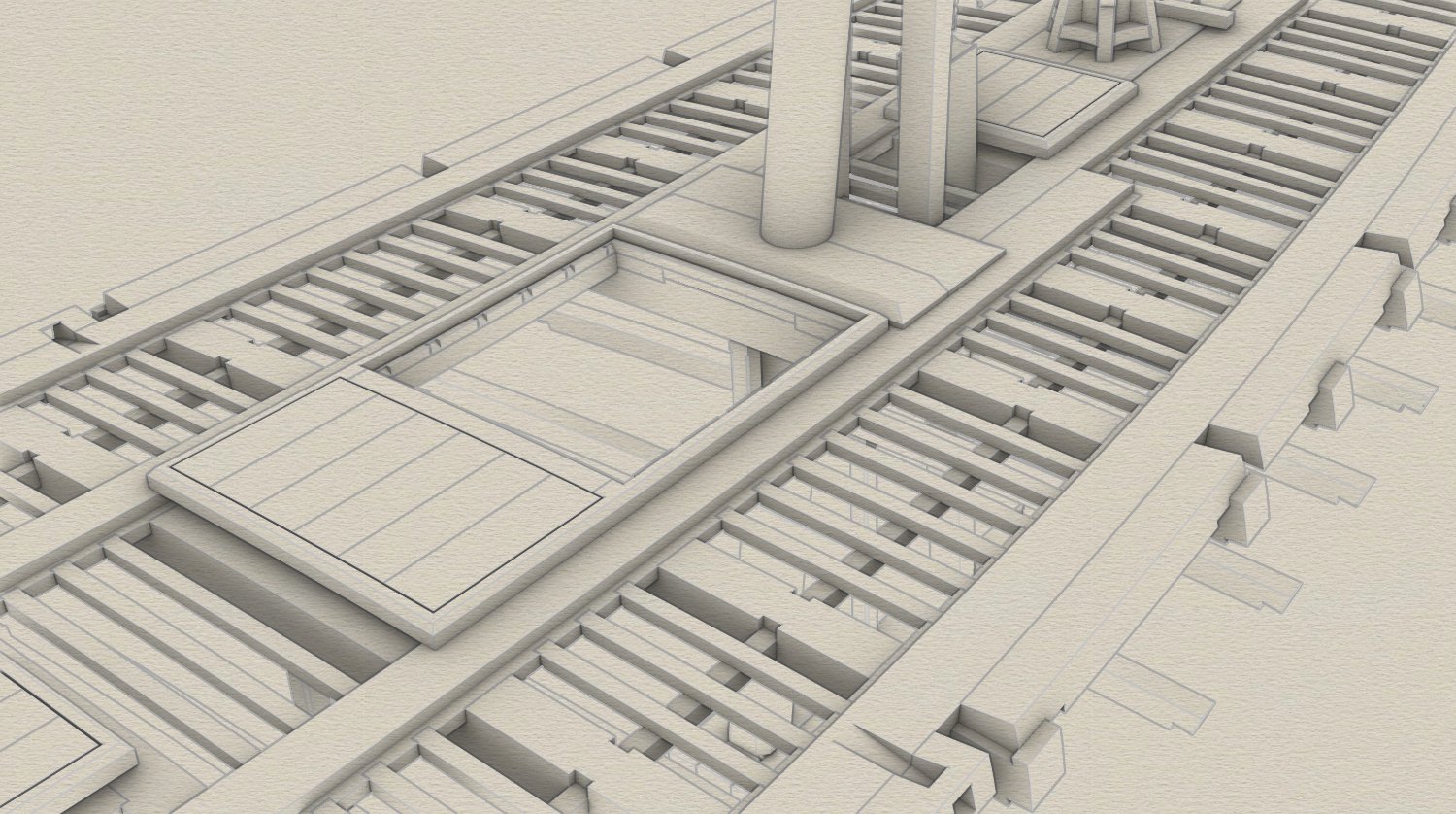
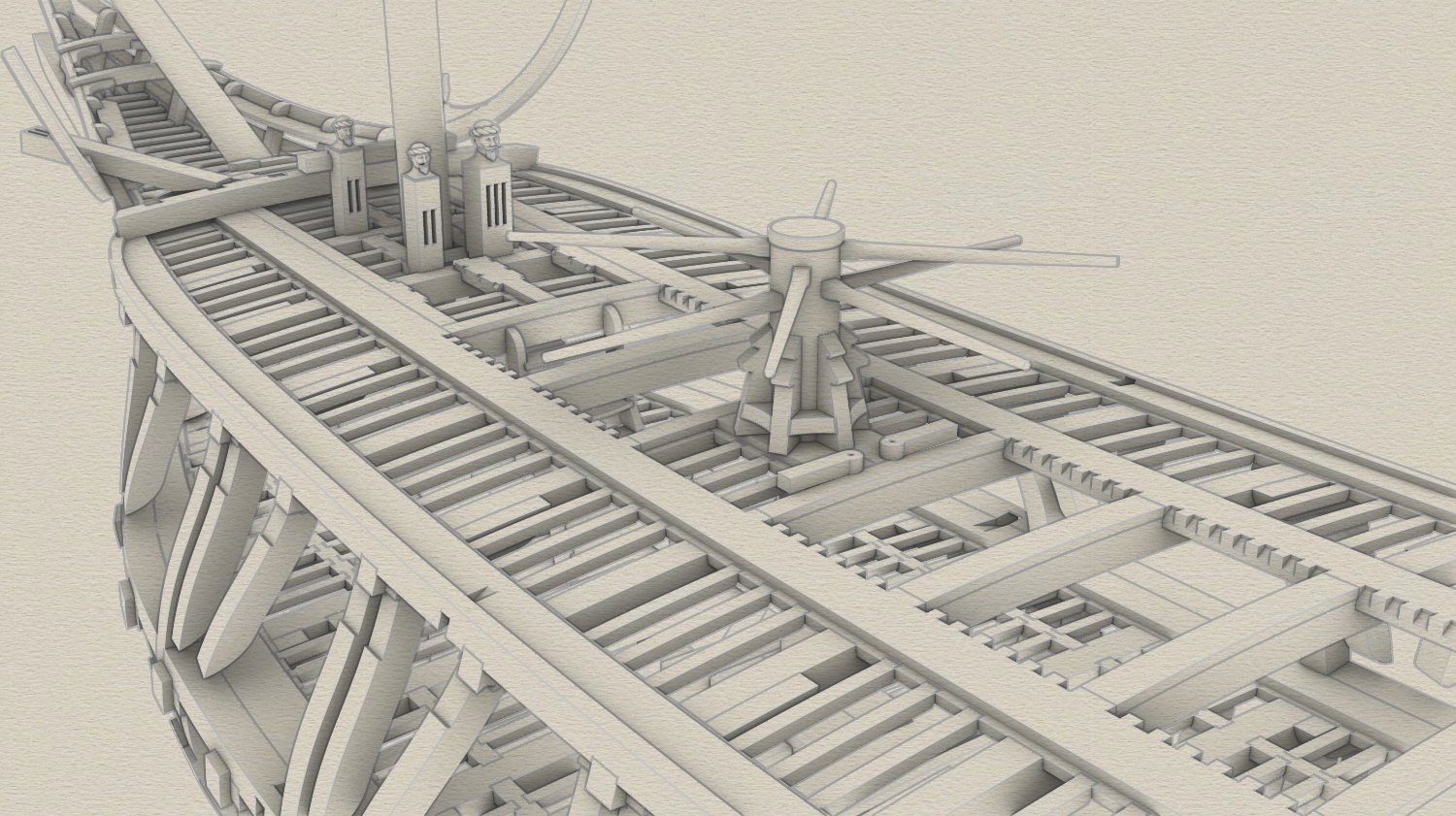
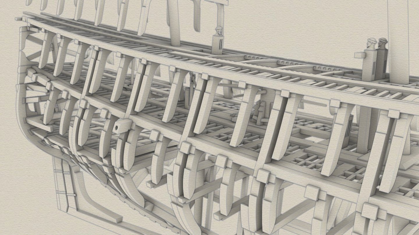
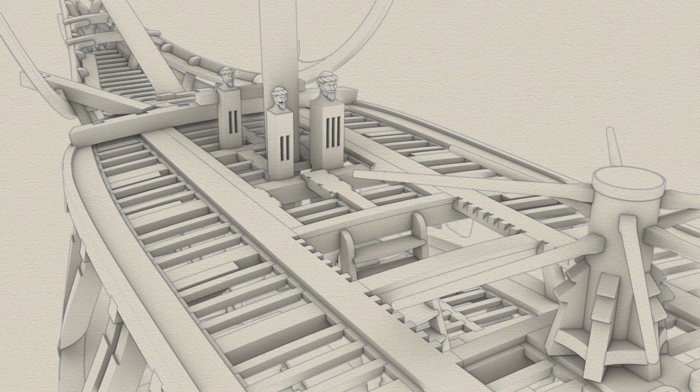
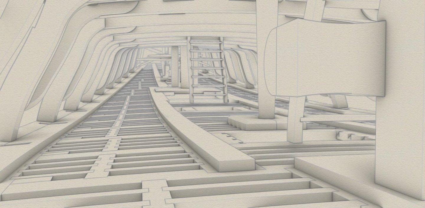
Still a small update. Aiming for standard solutions in this reconstruction, I have also slightly rearranged the layout of the gun deck (overloop) by replacing a number of carlings and ledges. Now carlings are beneath ledges as can be seen below.

-
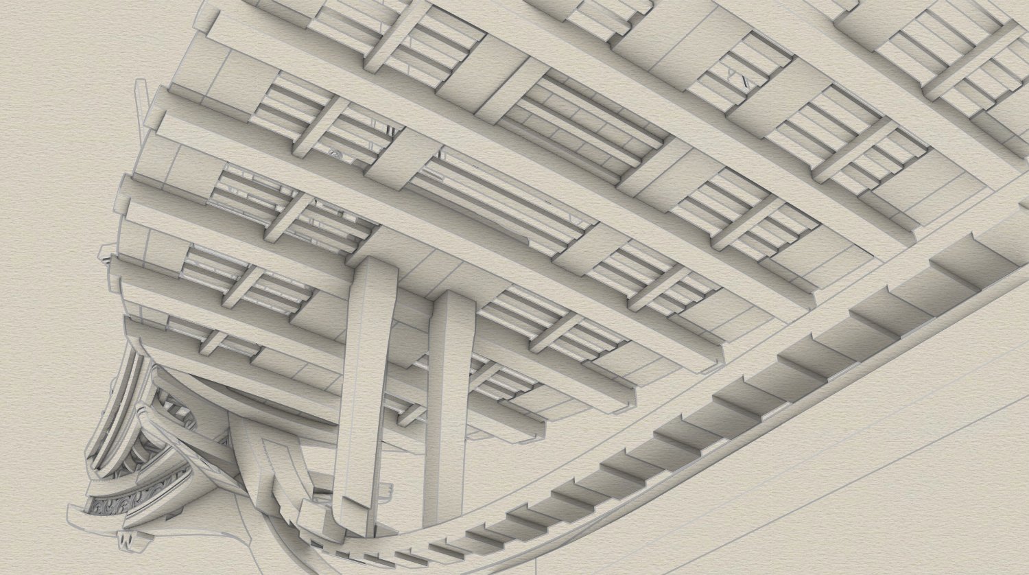
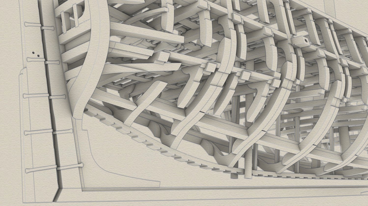
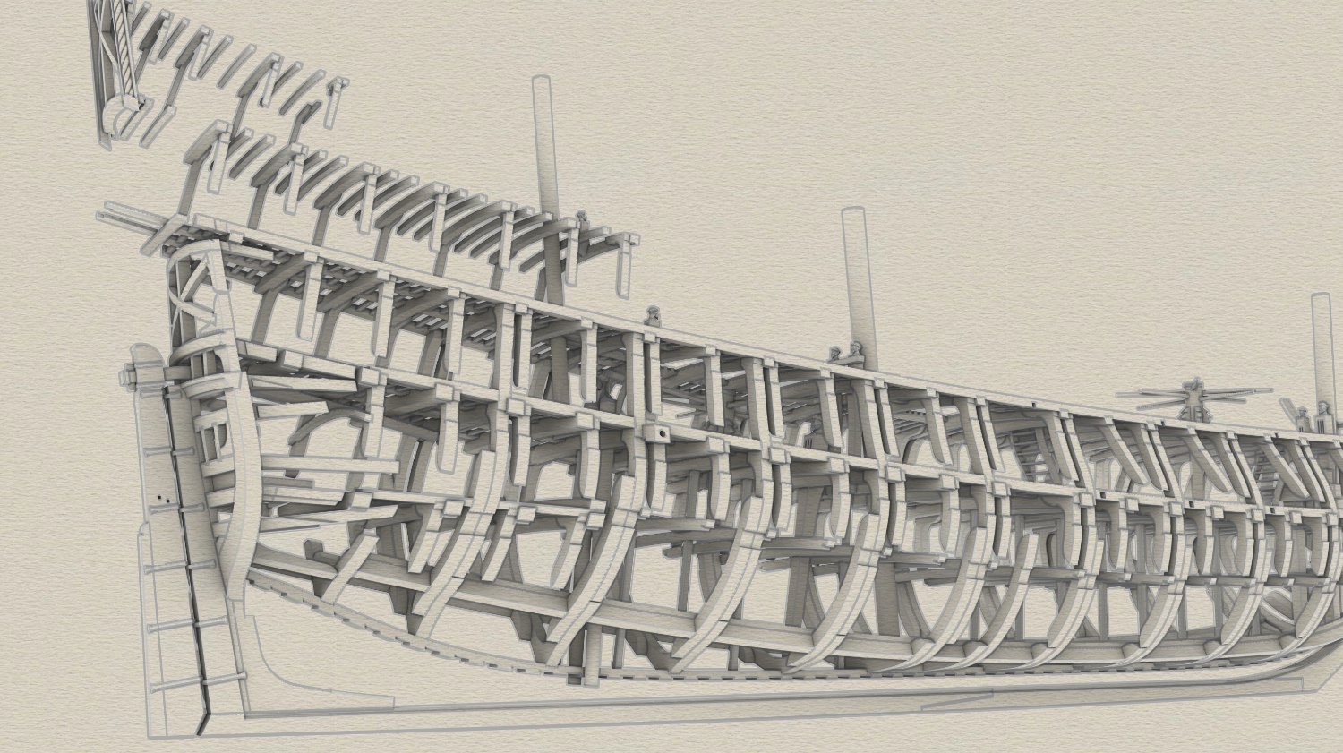
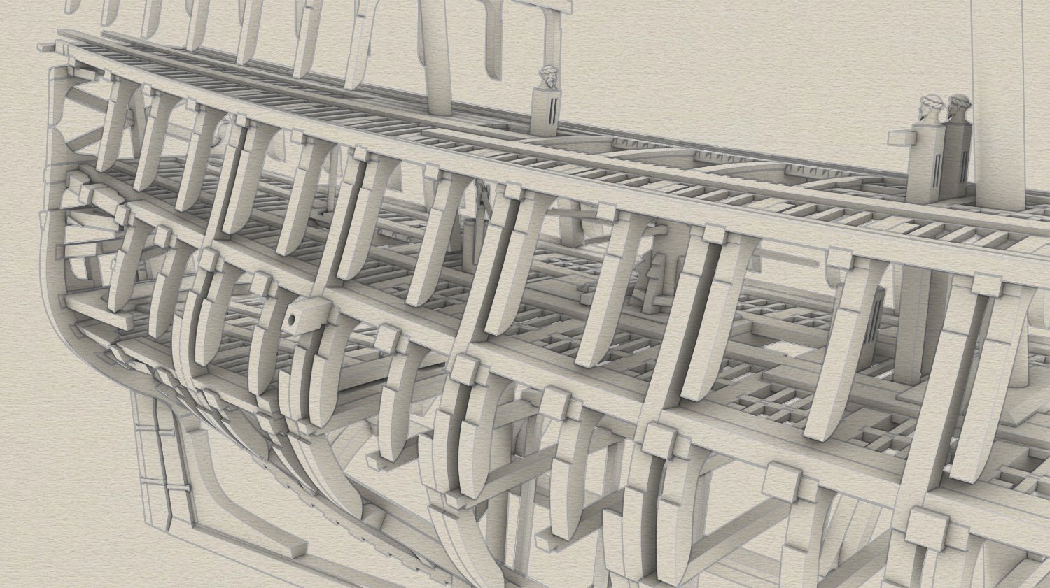
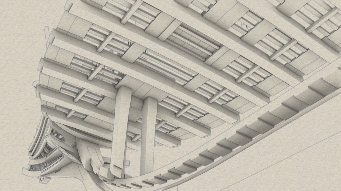
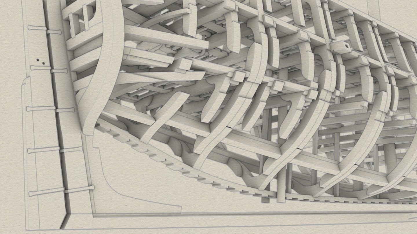
These renderings just for fun, taking a rest from preparing 2D draughts. Mostly structural elements with the frames hidden.


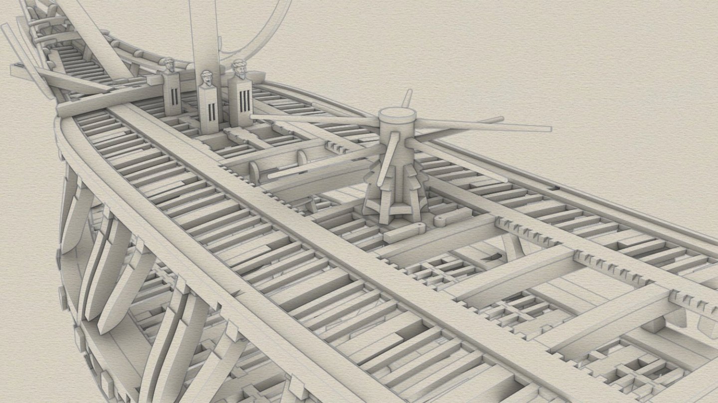
- 257 replies
-
- 14
-

-

-

-
Wow, thank you Tony. These are some of the most valuable compliments, especially coming from an already experienced digital model designer. It looks like we inspire each other, as it has long been a goal of mine to build a 3D ship model like your impressive Schooner Adventure or the pinas and later fluit-ship of the Ab Hoving/Rene Hendrickx duo. In this particular case, the original intention was ultimately to create two-dimensional plans that were precise and reliable in a geometrical sense, and in that sense my 3D model is merely a means to that end. But now you have made a clear suggestion, giving much food for thought. I am a little concerned about the rigging, as the digital model file of "St George" is already over 600 MB. And I am doing my best to reduce its size without compromising precision – defining the simplest possible shapes, rebuilding those unnecessarily complex, shrinking trimmed surfaces, reducing number of control points etc. I took a closer look at the rigging on your schooner looking for ideas on practical solutions. There is hope... 🙂
-
What a finely clean work! And sorry for being late. I am dreaming that my model would be built in such an attractive way and from the wood similar in appearance to your choice. "My" modellers suggest to use oak! Ghhrrffgth! 🙂