SteveA
-
Posts
45 -
Joined
-
Last visited
Content Type
Profiles
Forums
Gallery
Events
Everything posted by SteveA
-
 I have an Occre Xebec kit started that I am building more or less out of the box. Longer term build is a scratch 1:48 Syren brig using Chuck’s excellent instructions. I have a pile of cherry scraps and cut offs from furniture builds that I plan to use, we’ll see how it goes…
 -
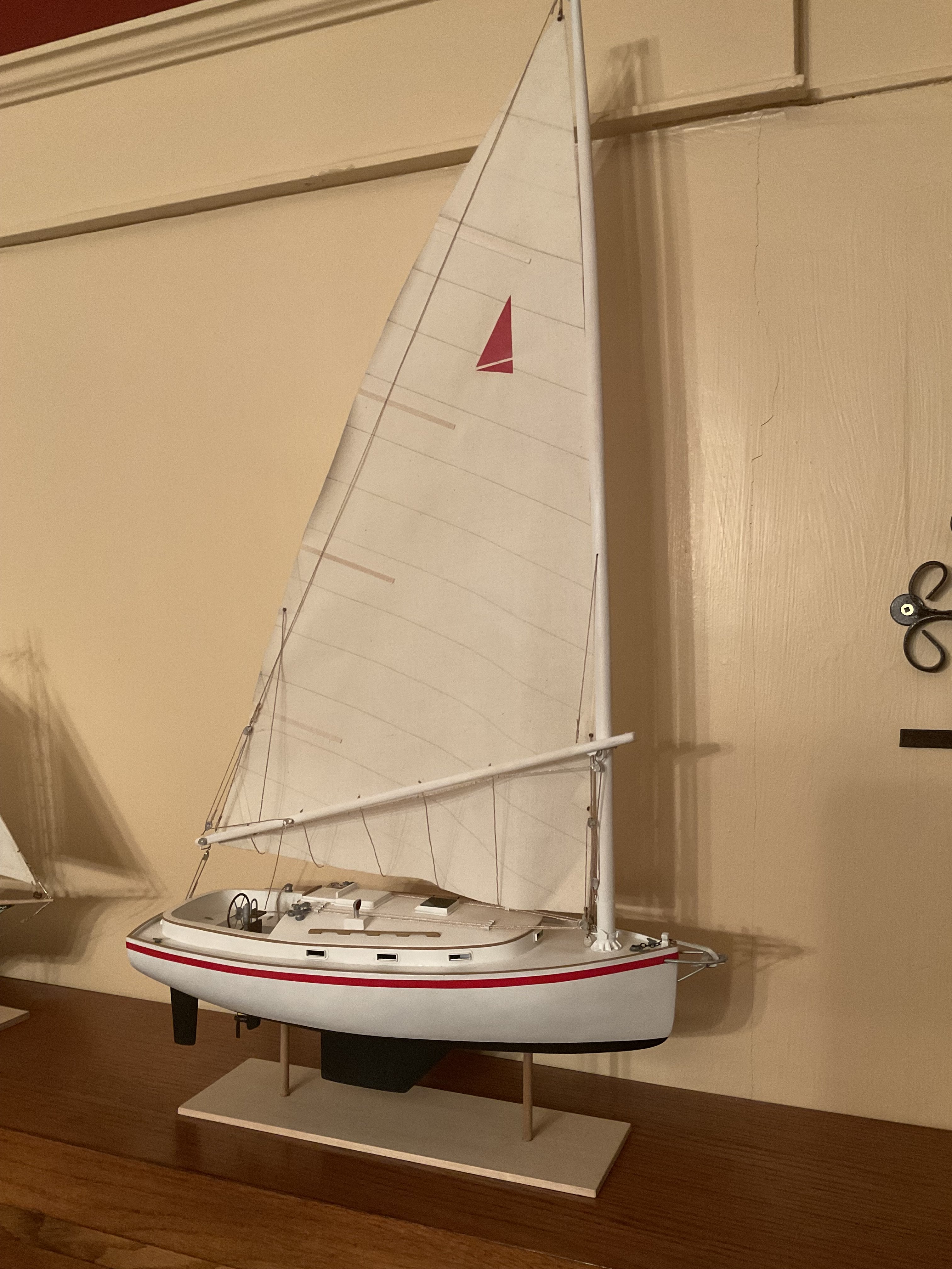
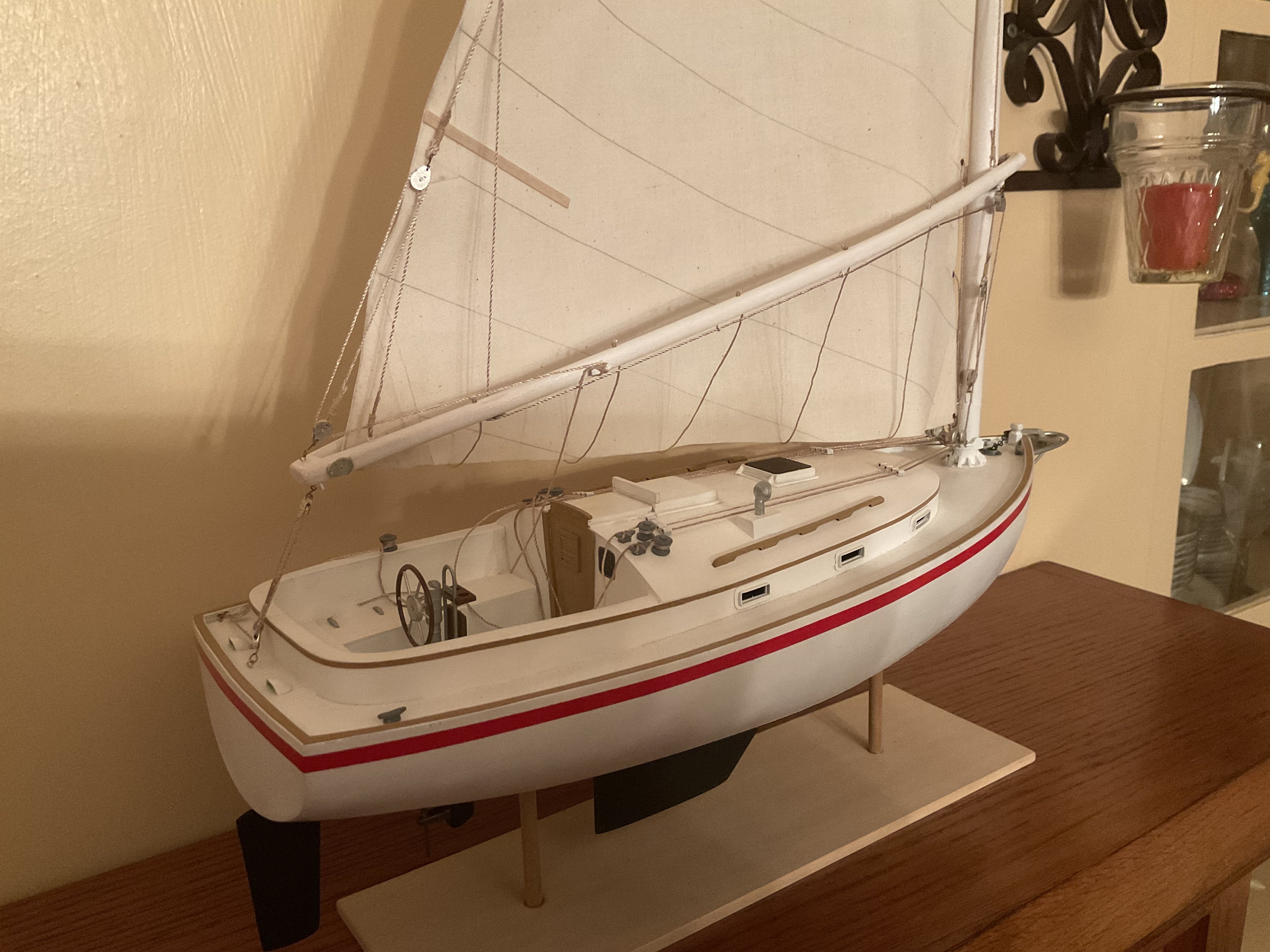
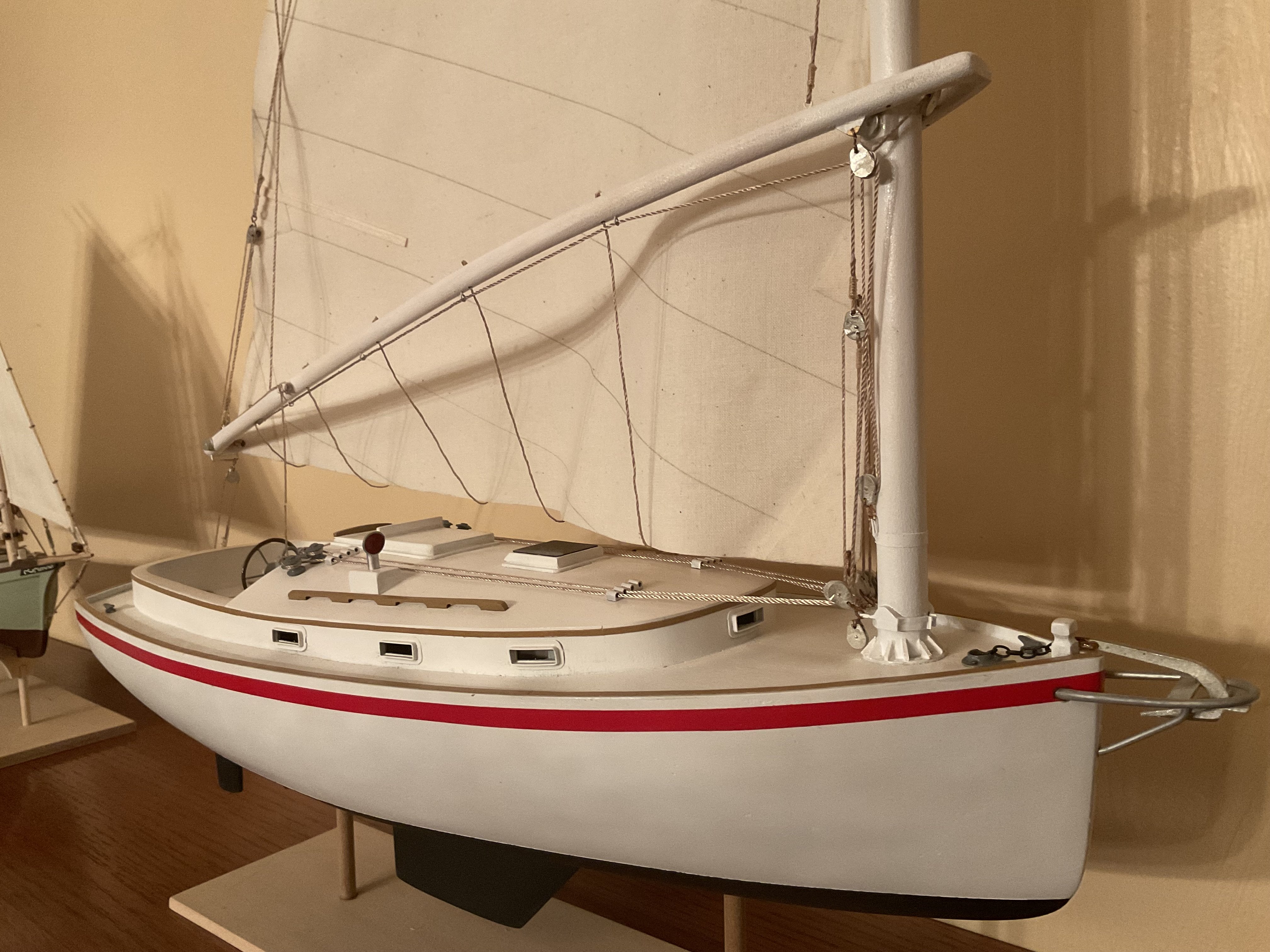
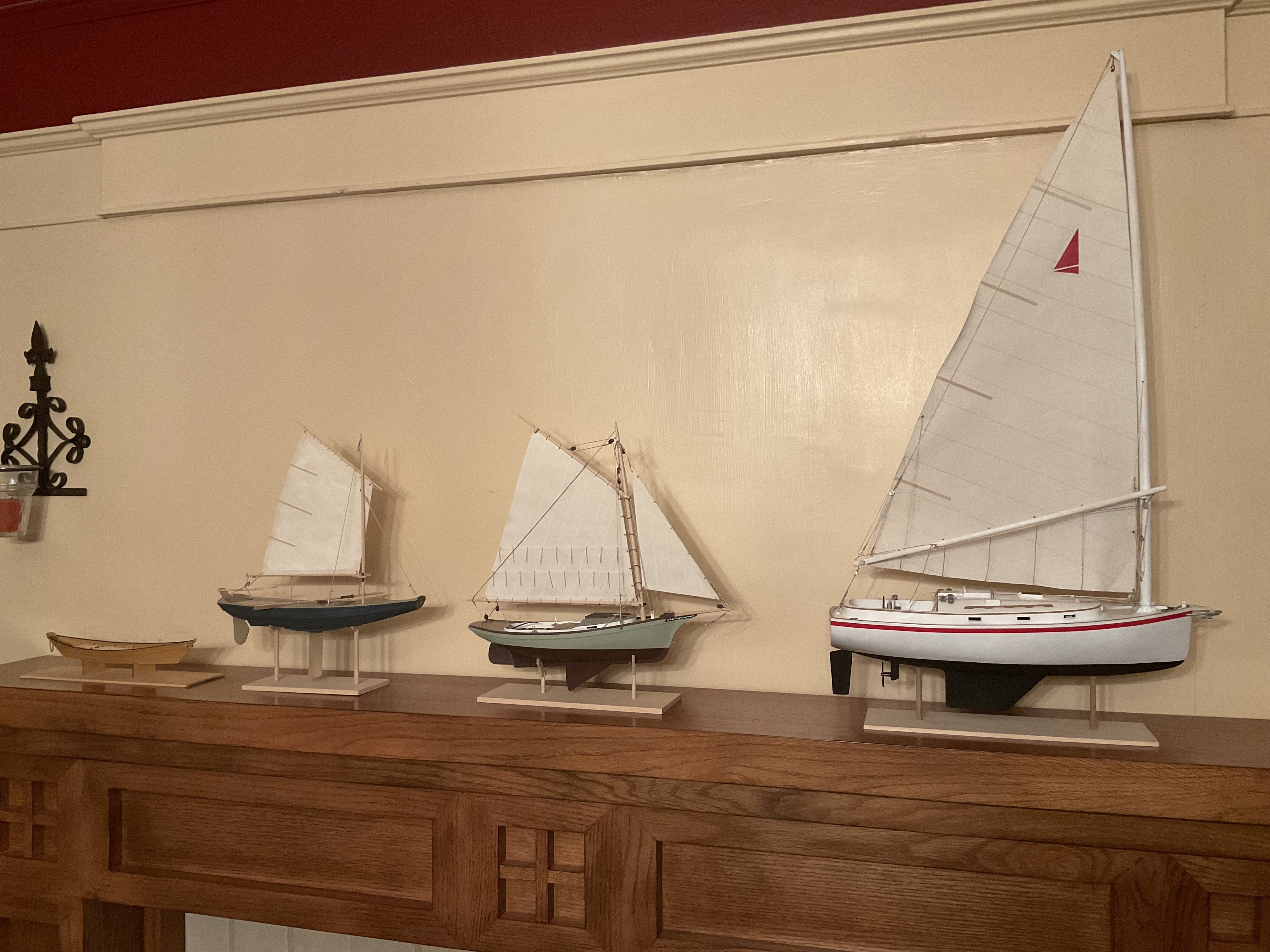
Yes! I completed the model a few months back. It is proudly sitting on the dining room mantle along with a few other David Antscherl designed kits. Thanks for asking, here are a few pics: Here is my collection in order of construction from left to right…


- 27 replies
-
- 7
-

-

-
- Nonsuch
- Model Shipways
- (and 1 more)
-
Just to clarify, when it says “Madera”, that just means wood in Spanish, it is a precut piece that you should be able to identify from the picture or drawing.
-
I looked at the Corsair instructions on the Occre website and it only shows sapelli, lime/sycamore, and walnut being supplied with the kit, same as my Occre Xebec kit. Sapelli is the brown wood with porous grain, typically used as a top finish surface in planking. Lime/sycamore is the cream colored wood used for dowels, under layer planking and decking in my kit. The thicker hardwood pieces may be dyed walnut. My kit has walnut pieces, but they aren’t colored like that. Walnut is typically used for deck furnishings, etc…
-
The 1836 brigantines Dolphin and Porpoise would make interesting model subjects. They were the last sub 100 foot two masters built for the U.S. navy and were considered excellent sailers, both having lengthy careers. Dolphin was burned at Norfolk in 1861. Porpoise took part in the 1853 Ringgold expedition, but was lost in the China Sea in 1854. At 1/4” scale, the hull would be around 22 inches between perps.
-
Your drawing looks correct, the false deck should extend to the edge of the slot so the bulwark pieces sit flush in the slot. It took me a while to figure this out as well.
-
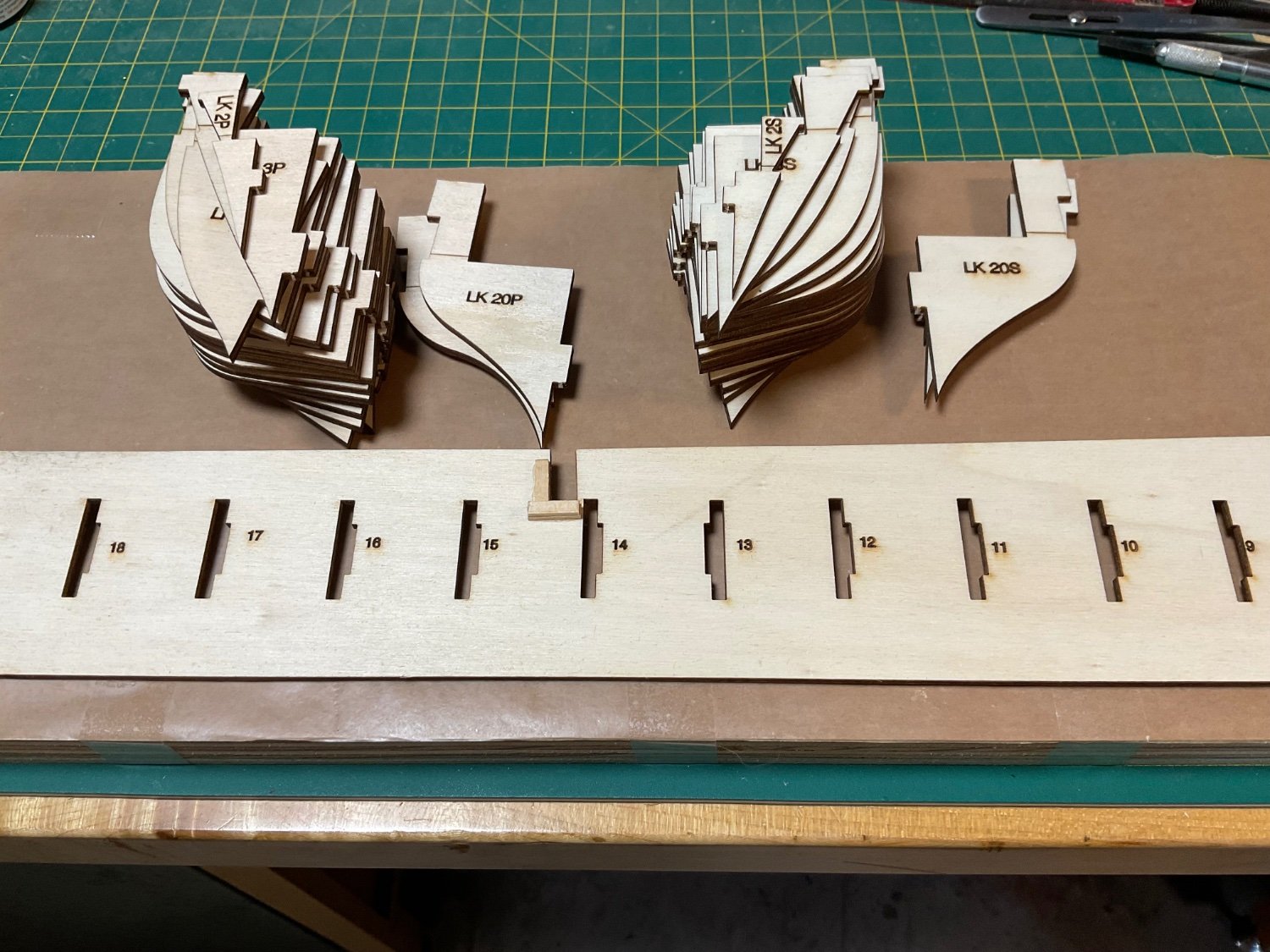
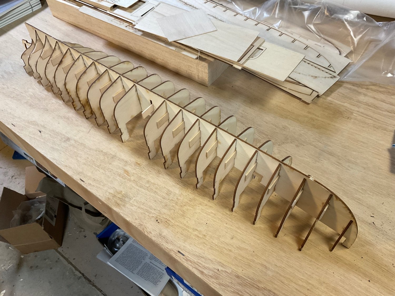
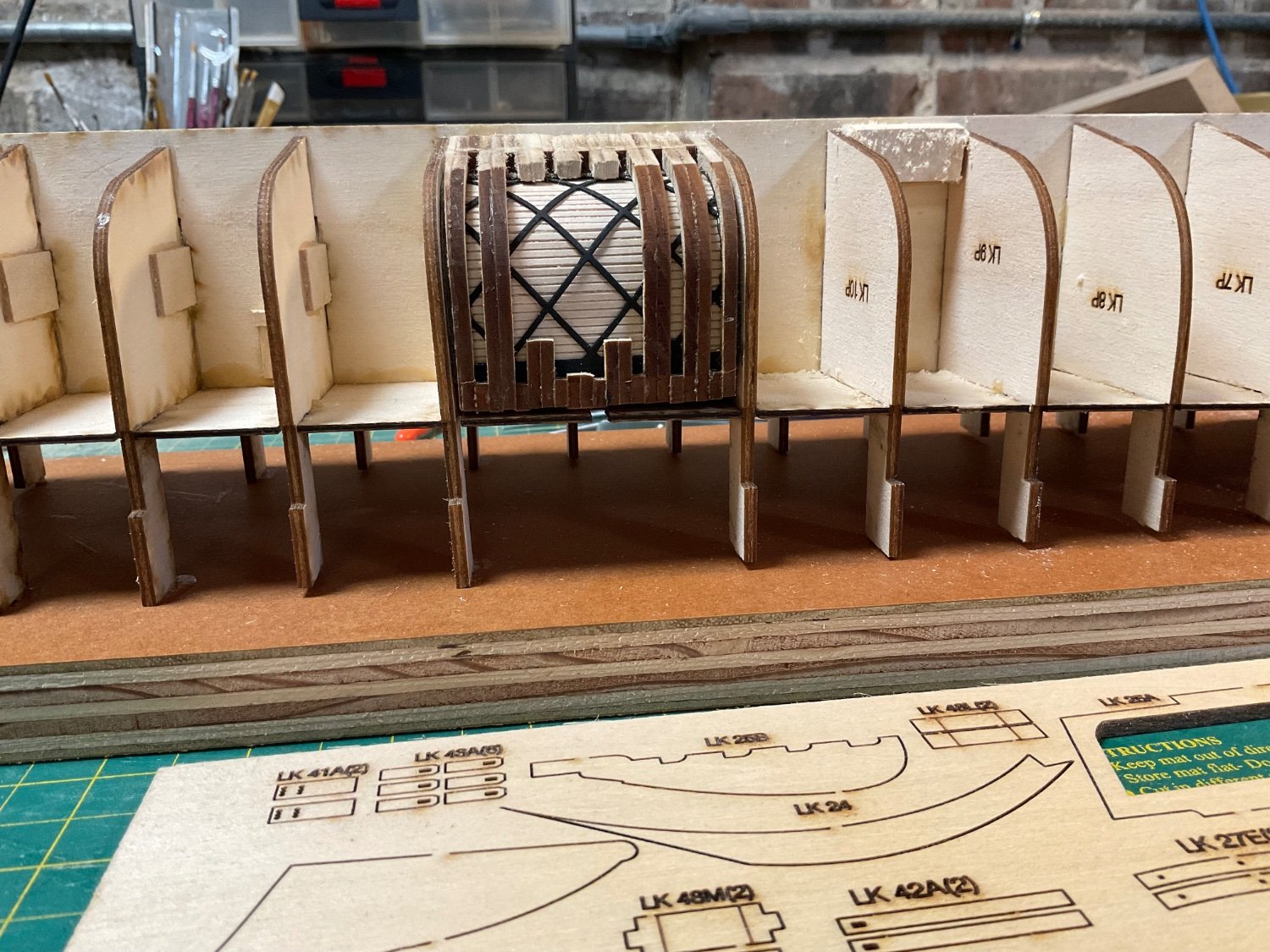
I’m starting a new build of the Civil War era USS Kearsarge as she appeared in the battle of Cherbourg on June 19, 1864, at least that is what Bluejacket was shooting for with this kit. Here are her specs from the Dictionary of American Naval Fighting Ships: Displacement: 1,550 tons Length: 201’ 4” Beam: 33’ 10” Draft: 14’ 3” Speed: 11 knots Complement: 163 Armament: two 11” Dahlgren, four 32-pdr., one 30-pdr. Dahlgren So far I’ve put together the bulkheads and sub deck, and glued it to the building board. I just started faring the hull for planking. This is my first Bluejacket kit and it looks like it will be a challenging build. They rank it as an advanced kit with previous building experience recommended. There appears to be a nice focus on detail as there are a lot of very tiny parts. I went ahead and ordered the optional copper plates, so this will be my first coppering attempt. The kit gives you the option of including a frame reveal section showing the iron cross bracing and chain armor, I will include this feature in my build.


- 1 reply
-
- 5
-
-
- kearsarge
- BlueJacket Shipcrafters
- (and 1 more)
-
Thanks! I appreciate the support and positive comments on this build. I’m in the home stretch now, with commencement of the rigging starting with the hanger and choker lines:
- 27 replies
-
- 5
-
-
- Nonsuch
- Model Shipways
- (and 1 more)
-
I really appreciate this discussion, very informative! So following the recommendations, I need to look for an iron folding anchor with a shank length around 50 mm. The anchor will be lashed to ring bolts added to the deck. I just received a used copy of The History of American Sailing Ships by Chapelle today. It does look like the AL Dallas kit was based on the 80-ton Doughty design shown in Figure 32. Chapelle speculated that the Dallas and her sister ship Surprise were of the 80 ton variety.
- 24 replies
-
- 1
-
-
- anchor handling
- schooner
- (and 1 more)
-
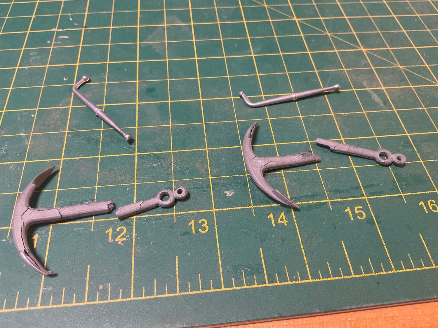
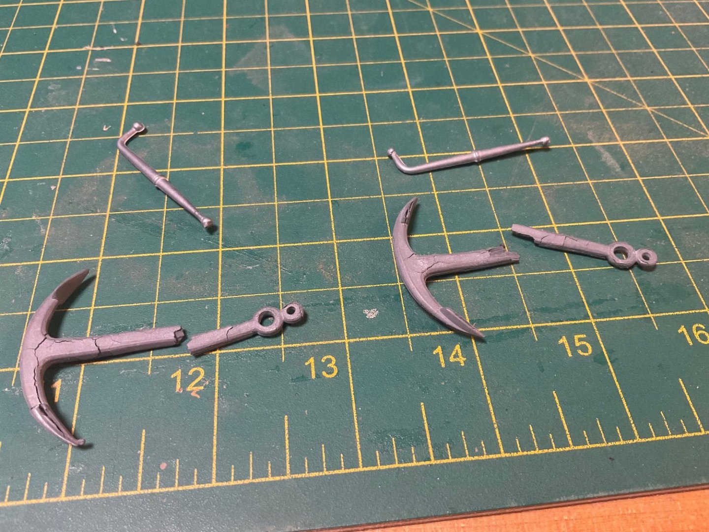
As it happens, I won’t be using the kit supplied anchors regardless of scale or period correctness. I just opened the bag they were in and they fell apart. I don’t know what they are made from, but it looks like the anchors would have eventually disintegrated even if installed when the kit was new. The carronade barrel was unusable as well. The kit box has a copyright date of 1978. Now I need to look for appropriate replacements for a revenue cutter circa 1815 around 1:50 scale.
- 24 replies
-
- 2
-

-
- anchor handling
- schooner
- (and 1 more)
-
I thought it odd as well to secure such a heavy object to a stanchion. Perhaps the anchor was secured to the knighthead and bowsprit bitts in some fashion?
- 24 replies
-
- 1
-
-
- anchor handling
- schooner
- (and 1 more)
-
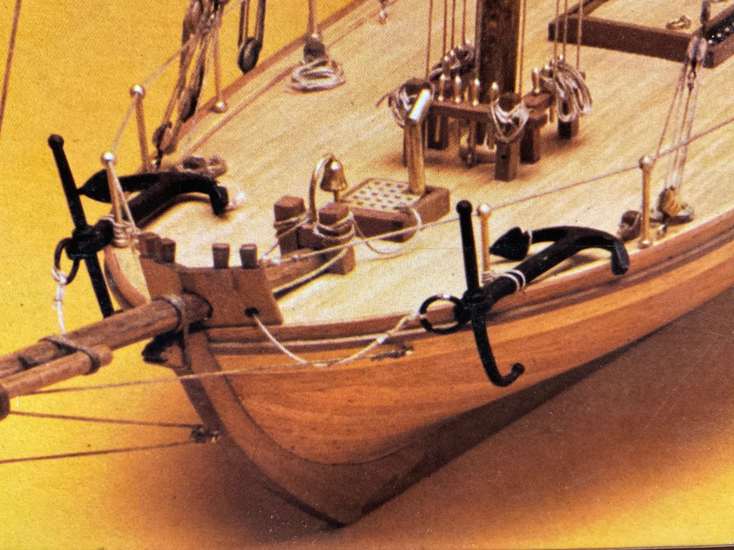
I have an old Revenue Cutter kit that I work on occasionally, the AL Dallas kit now discontinued. Anyway, the instructions and plans make no mention about rigging the anchors. The only clue is from the picture on the box. It looks like the anchors are loosely secured around the Bowsprit Bitt and then through the grating. The anchor is also lashed to a railing stanchion and the fluke is secured to the Bowsprit Bitt. Does this seem like a reasonable way to rig the anchors?

- 24 replies
-
- 1
-
-
- anchor handling
- schooner
- (and 1 more)
-
USS Kearsarge deck planking
SteveA replied to SteveA's topic in Building, Framing, Planking and plating a ships hull and deck
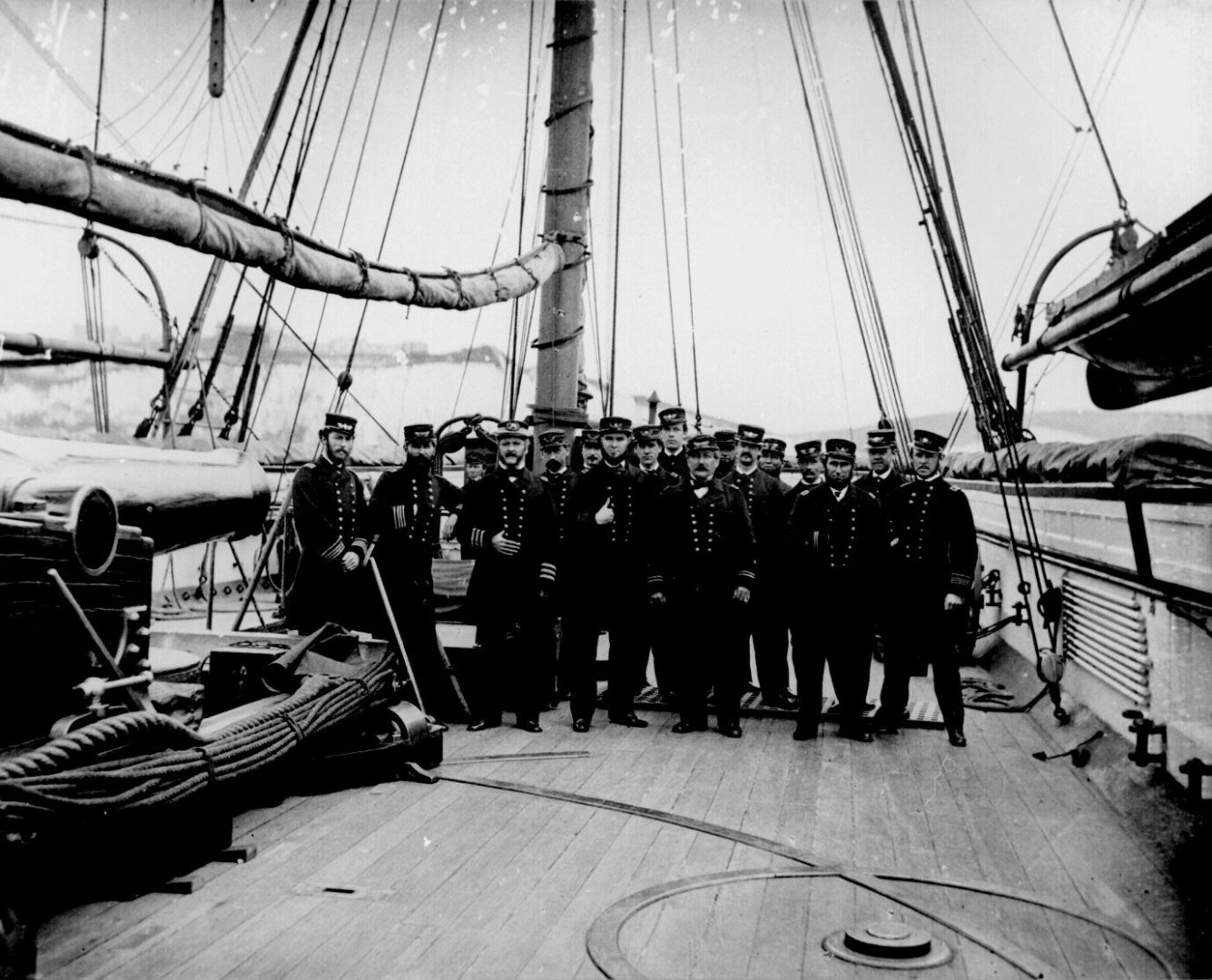
Keith, thanks for providing the picture of the Tennessee deck, clearly showing the parallel decking. I plan to use the glued-up decking from Bluejacket as I have seen no evidence that tapered decks were used for ships of the Kearsarge period. There was a series of articles by Arthur C. Roberts on his Kearsarge model build in NRJ volumes 44 and 45. The pictures of his model show straight decking as well. -
USS Kearsarge deck planking
SteveA replied to SteveA's topic in Building, Framing, Planking and plating a ships hull and deck
Nic at Bluejacket said the weather decks should have been cut from glued-up decking and will be sending new parts to me. So it looks like I will be saved from having to lay down deck planks. -
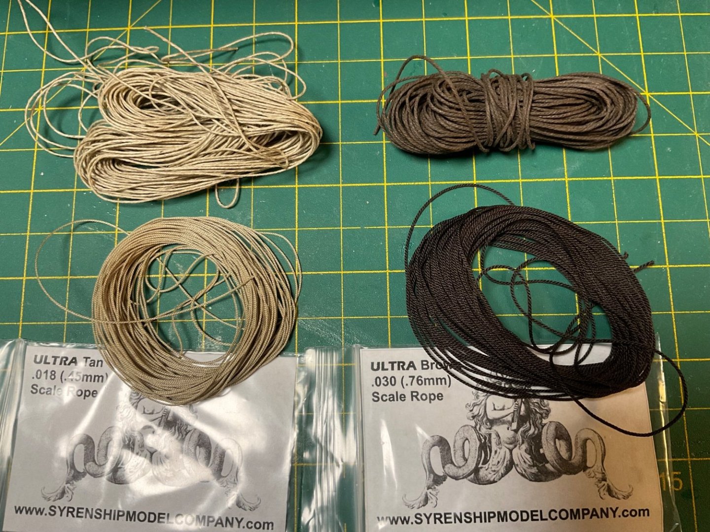
I received some replacement rigging from Syren. I ordered the closest in size I could get to the rigging provided in the model kit. I have to say I’m impressed with the quality of the Syren scale rope. I really like how sharp the details are and even the sheen on the rope. This will look a lot better than what came with the kit, especially the tan running rigging as can be seen in the comparison photo. The top rope is from the kit.
-
I am just starting a Bluejacket kit on the Kearsarge and noticed that the provided weather decks are not scribed for deck planking as is shown in the instruction manual. I was thinking about planking the deck with wood strips for a more realistic look anyway. I was just wondering if the deck planks should be tapered or straight? I can’t really tell from this picture but at least I can approximate the width. Are there any resources showing deck plank layouts for warships of this era?
-
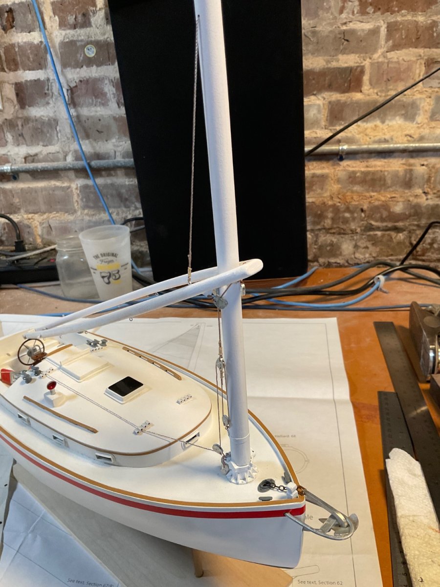
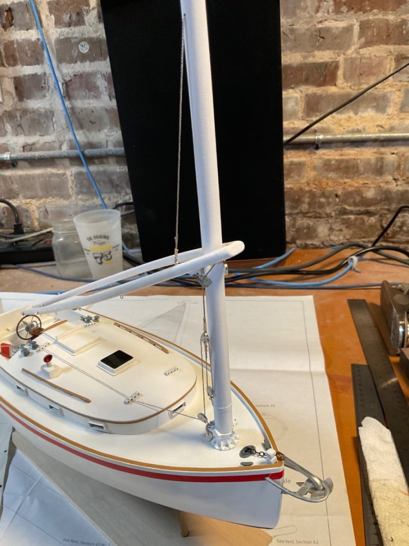
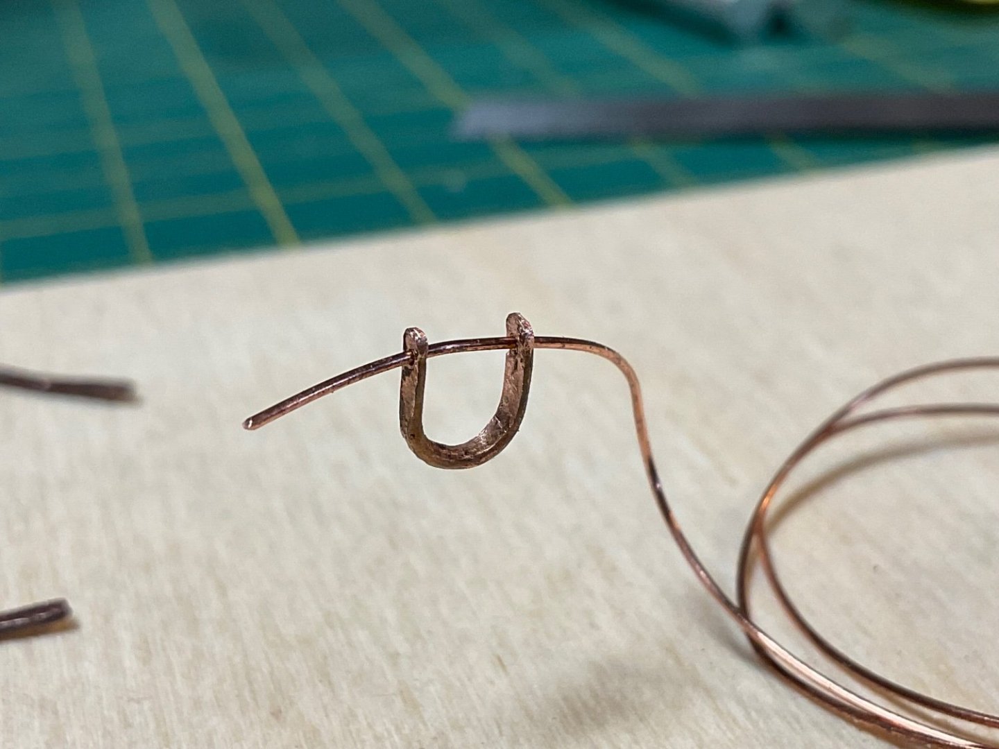
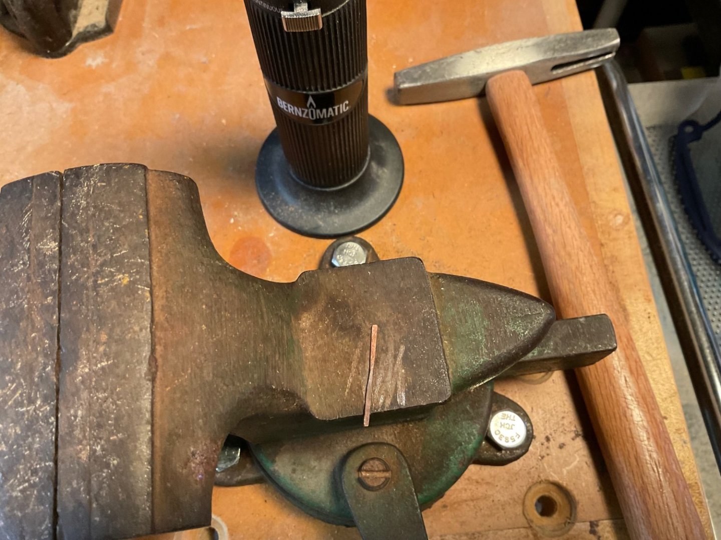
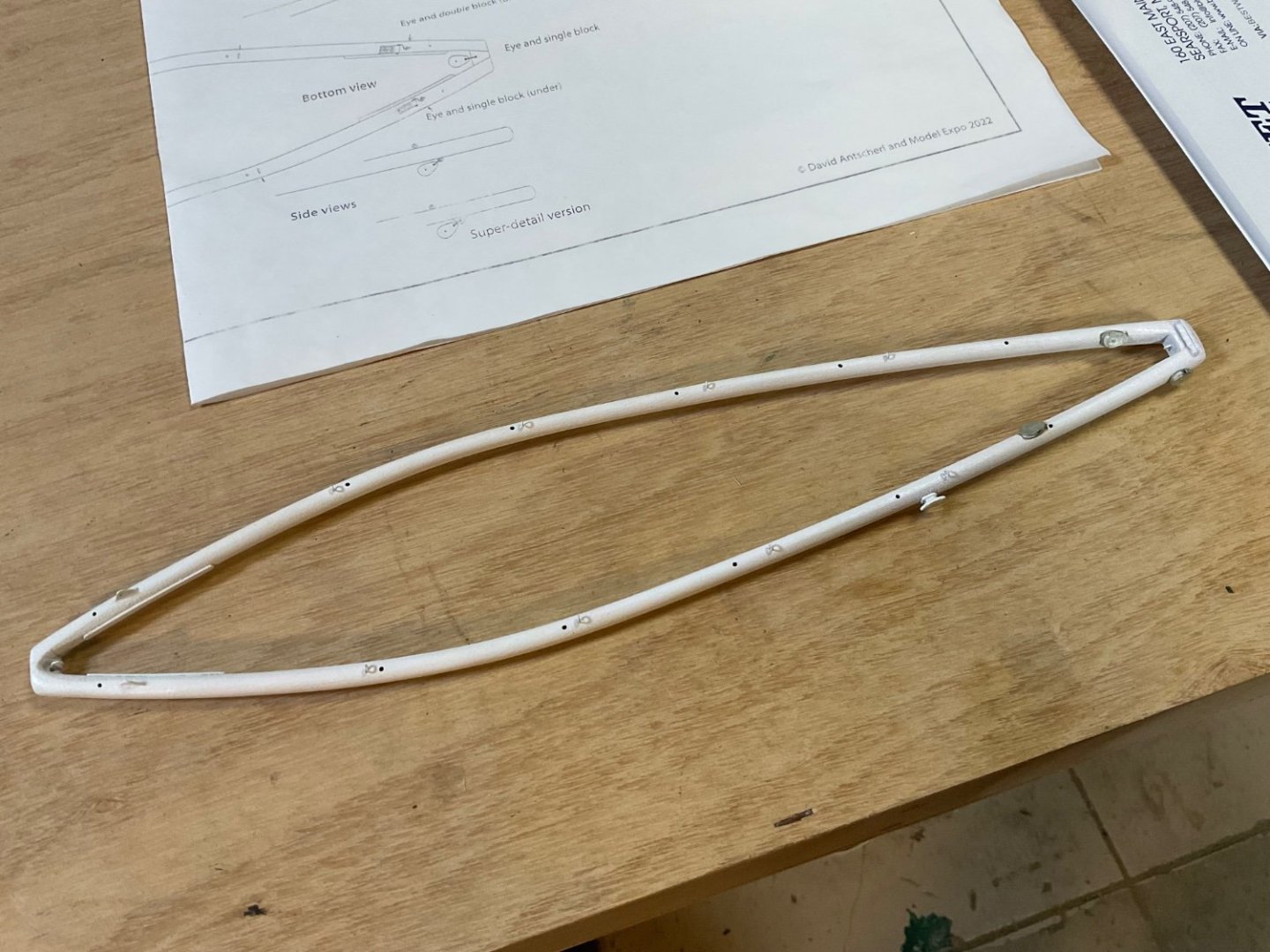
Still making slow progress on this kit. I have just about all the hull and cabin fittings attached and the main mast and wishboom are ready to be installed. The anchor is attached to a chain with a shackle which need to be made. I found these to be rather challenging to fabricate. You have to flatten some 18 gauge wire in order to drill small holes in the ends to pass 24 gauge wire. This is my first success, the model requires 4 to be made in all.

- 27 replies
-
- 6
-
-
- Nonsuch
- Model Shipways
- (and 1 more)
-
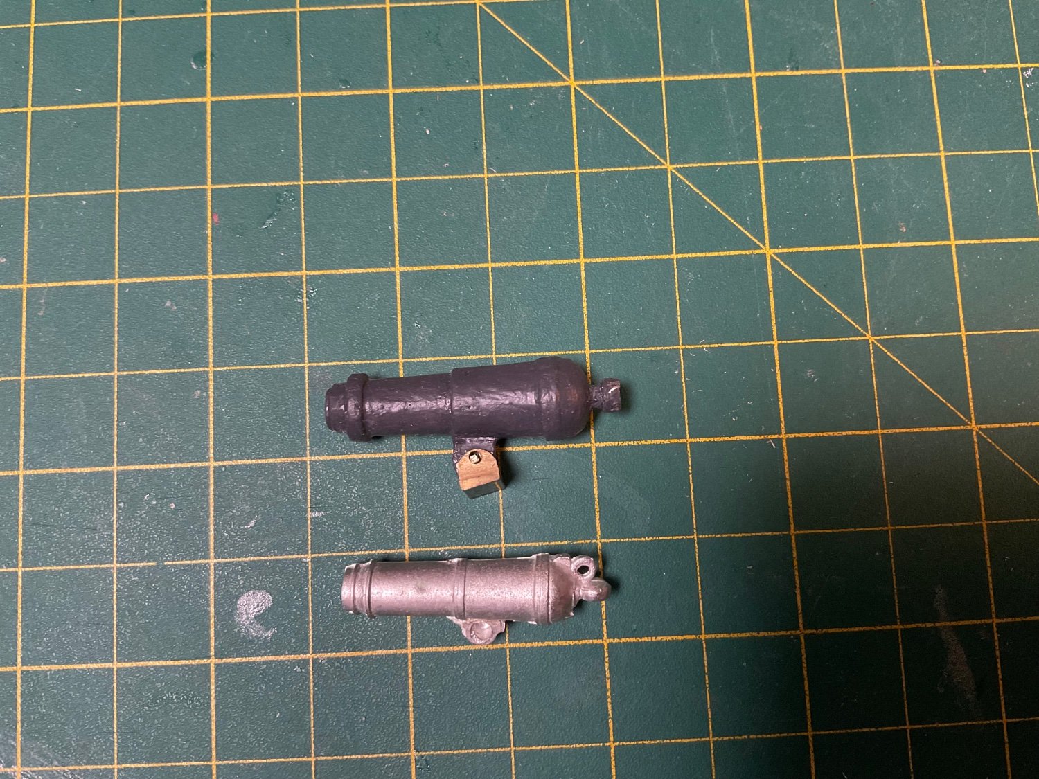
I got a replacement carronade from Bluejacket (bottom one in picture), this was the closest one in size I could find to the one included in the kit. I assume it’s the same one supplied in their 1:48 revenue cutter model. I cleaned up the flash, built a new support for it and painted it with Tamiya bronze. It is now rigged up on the bridge. After working with the kit supplied rigging, I can see where some better aftermarket rigging line would be a significant upgrade. I’ll order some replacement rigging line and start the masting process.

-
Oh well, I guess it was wishful thinking on my part for something other than another Constitution or Victory iteration. 😴
-
They gave it away with the 1765 clue, must be the Bonhomme Richard.
-
Thanks! Yes, the wishbone was a fun little build. I just started outfitting the main mast.
- 27 replies
-
- 3
-
-
- Nonsuch
- Model Shipways
- (and 1 more)
-
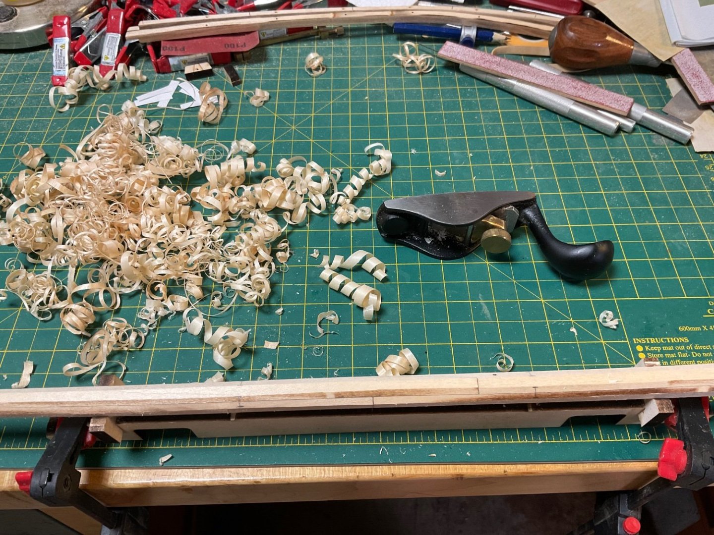
I finally have a paint scheme for this model with some input from family members. It looks interesting at least: Working on main mast now. The kit provides a nice jig to get to “eight-square”. I used a no. 100 plane which makes some nice shavings!

- 27 replies
-
- 5
-
-
- Nonsuch
- Model Shipways
- (and 1 more)
-
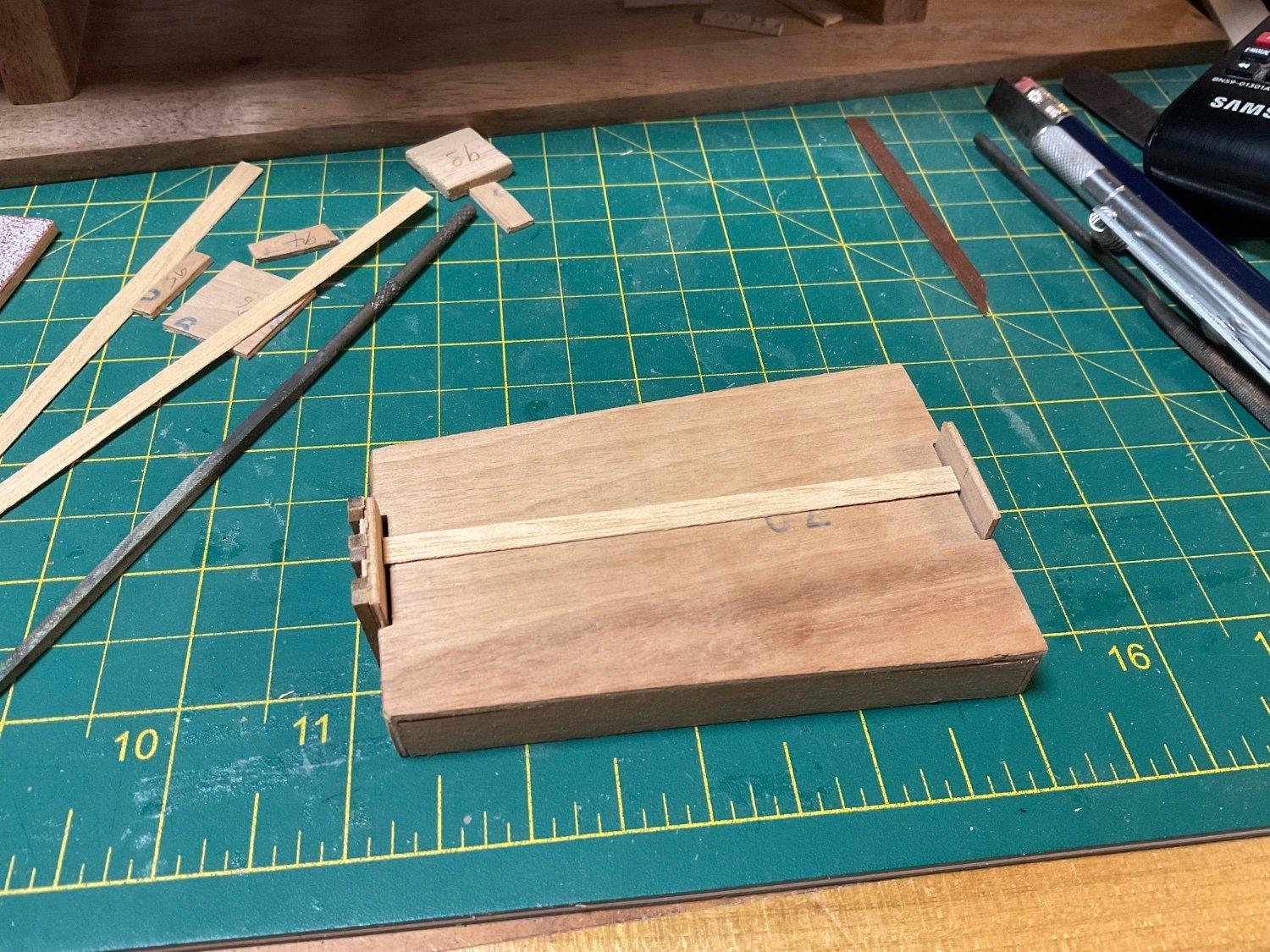
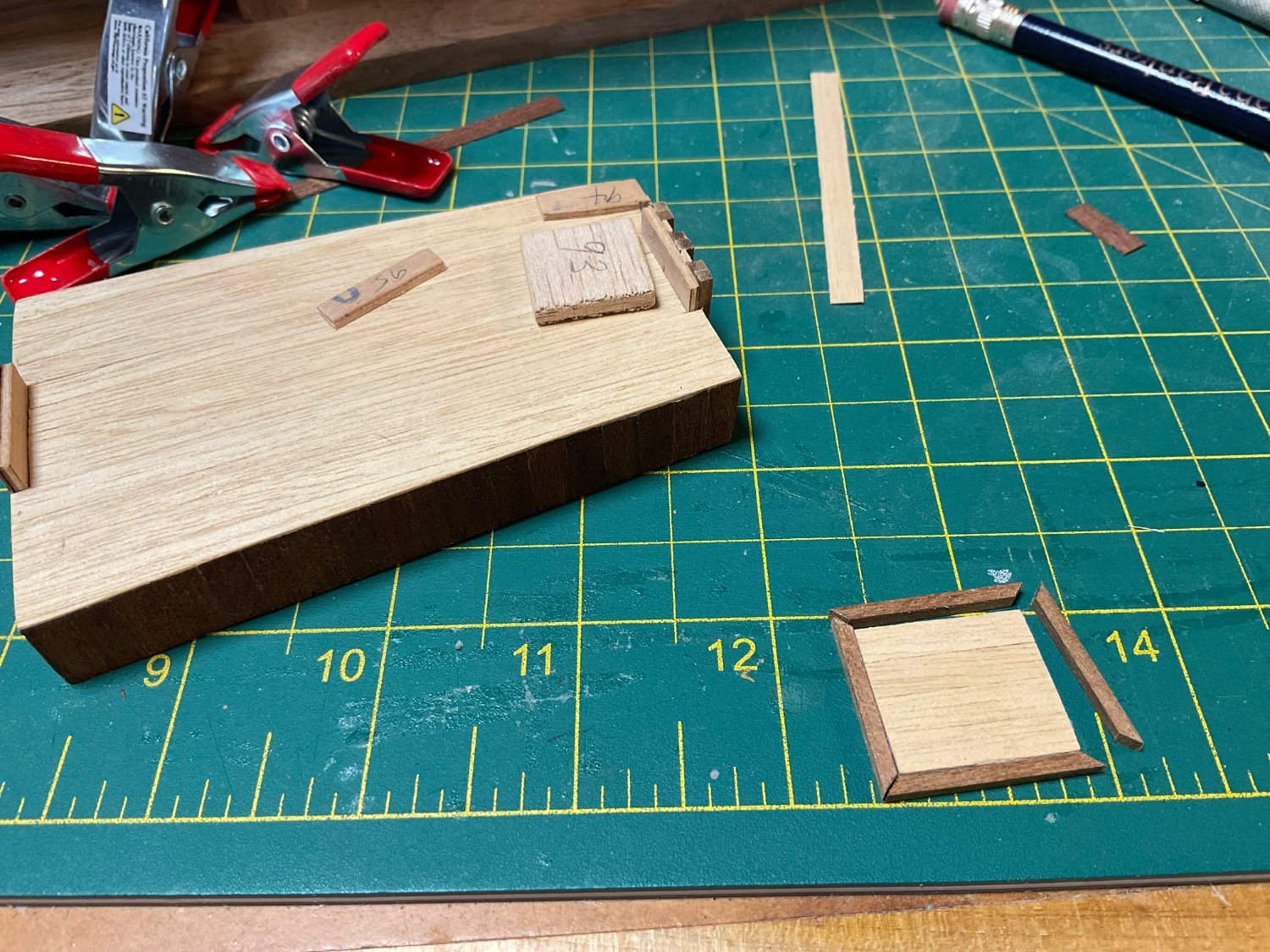
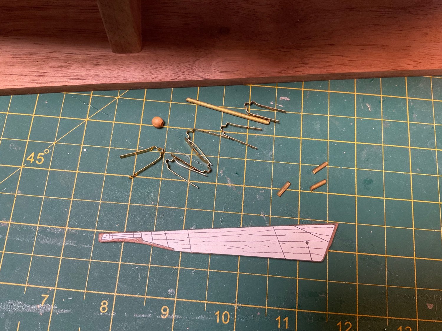
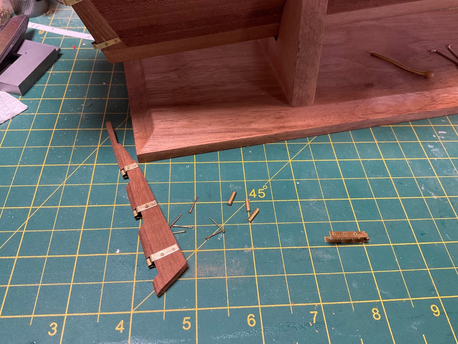
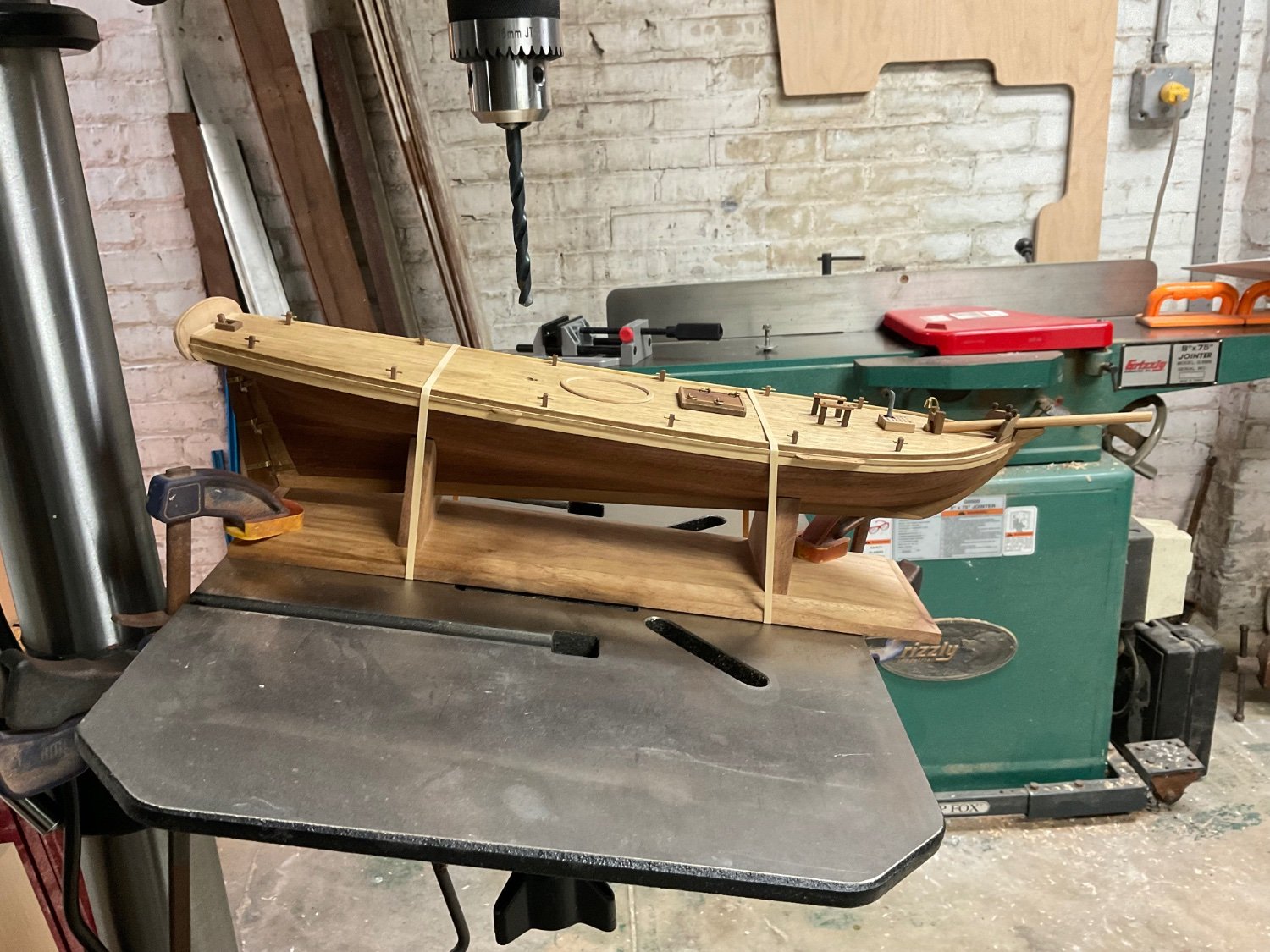
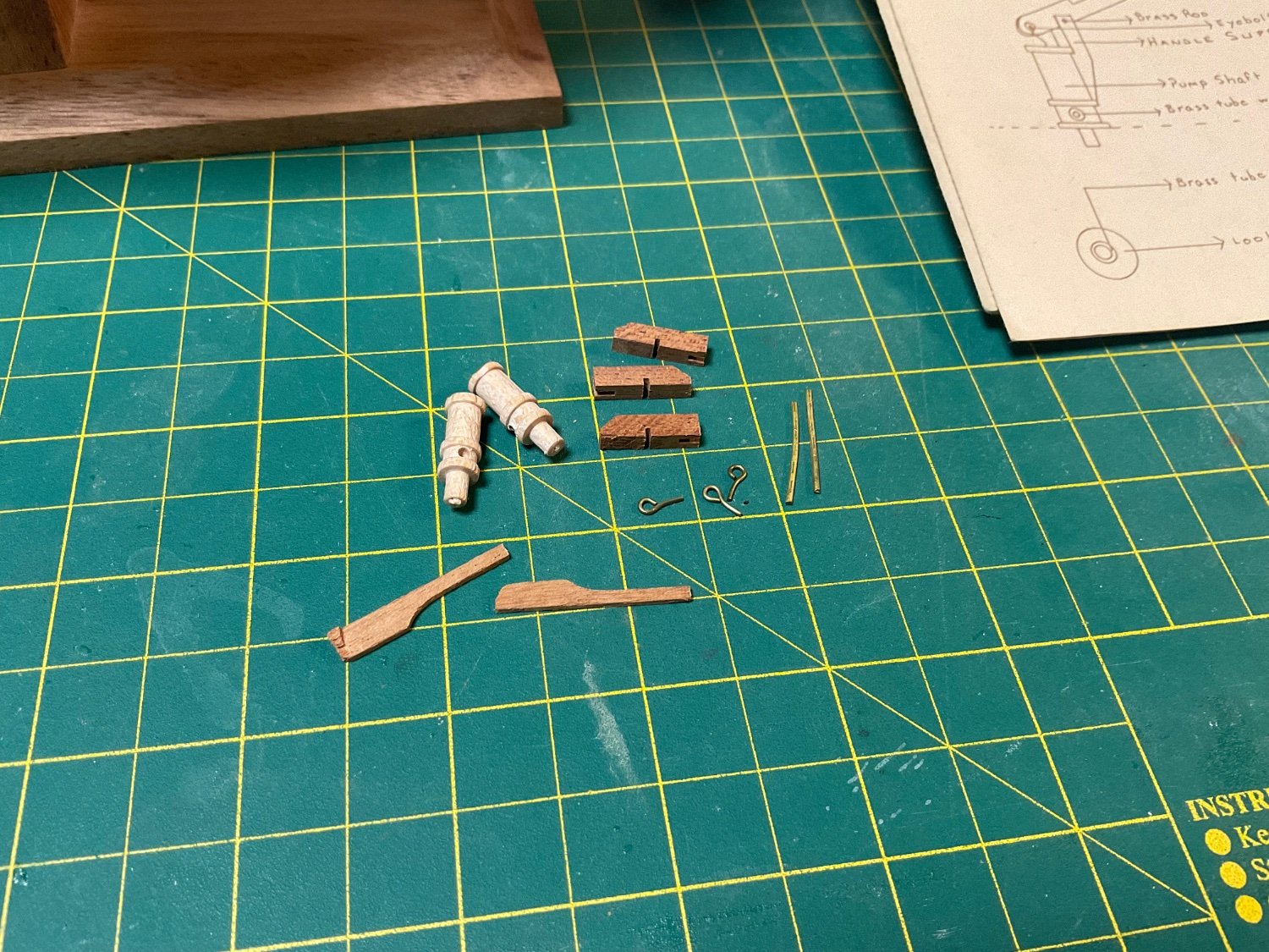
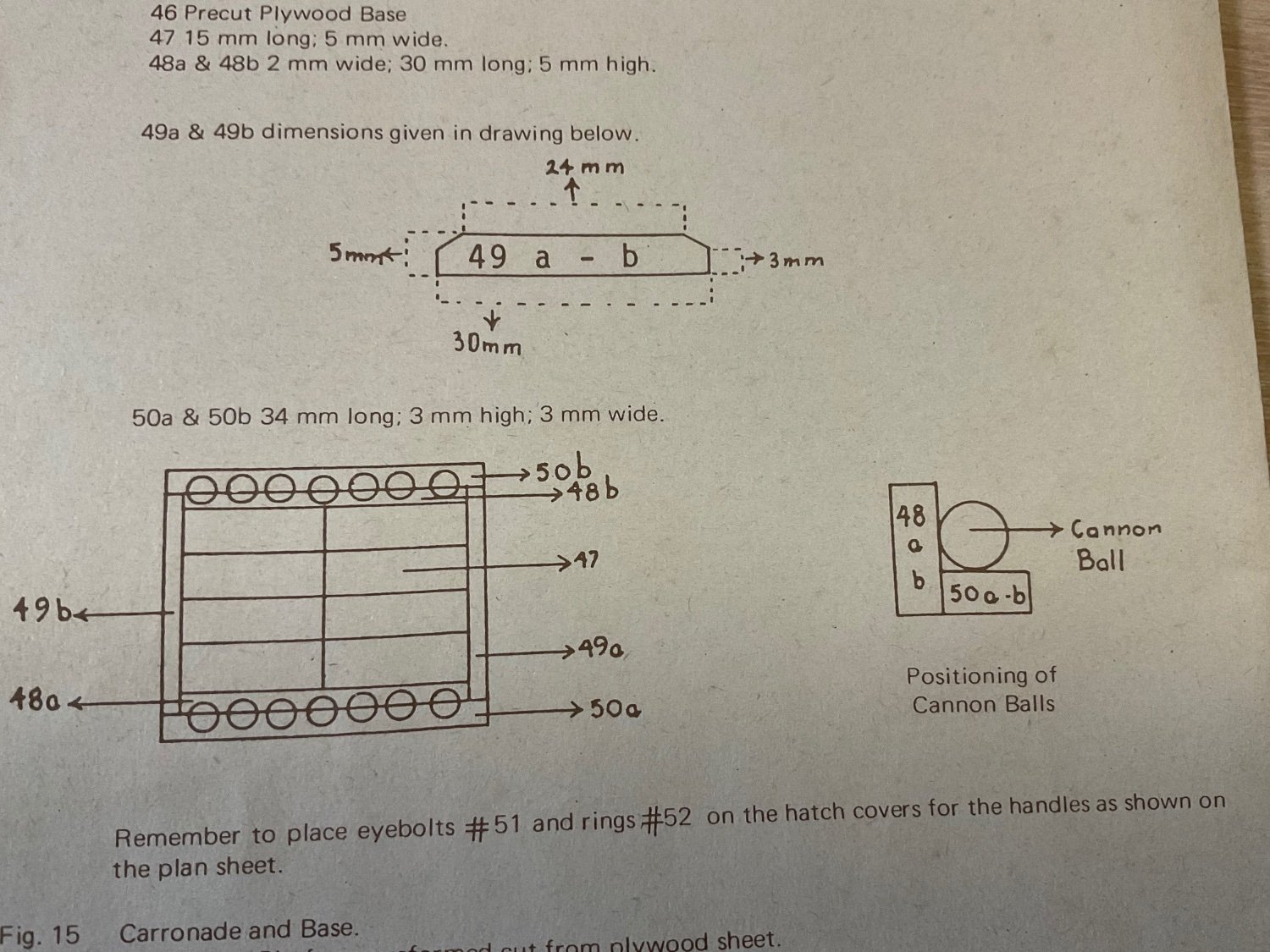
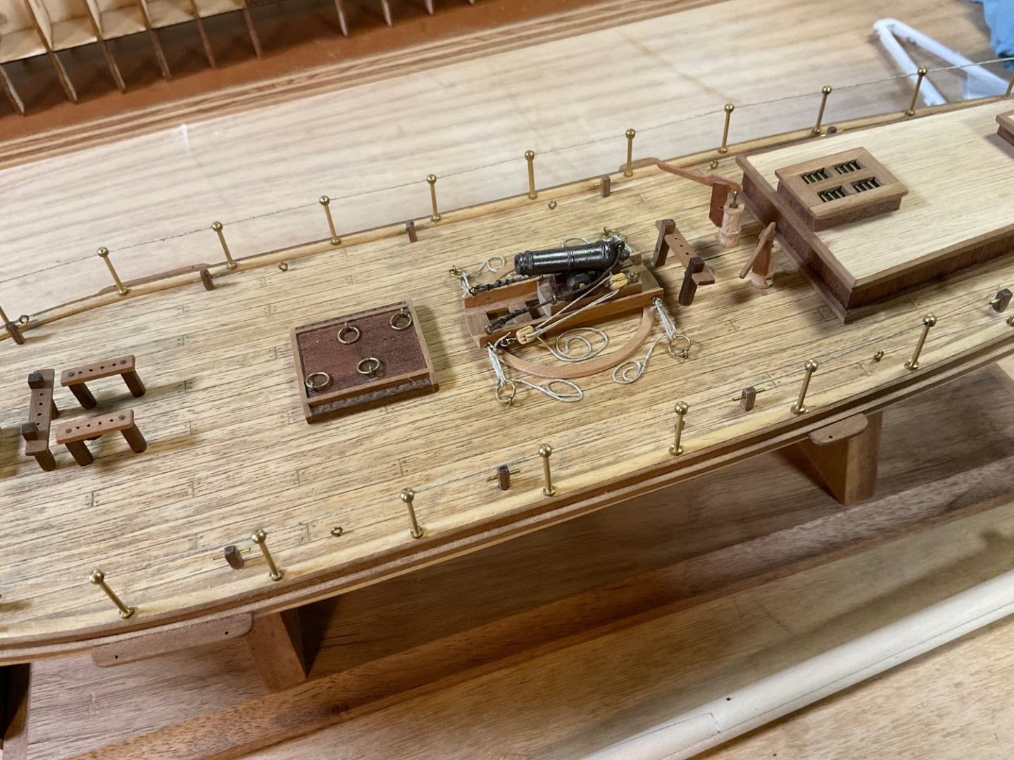
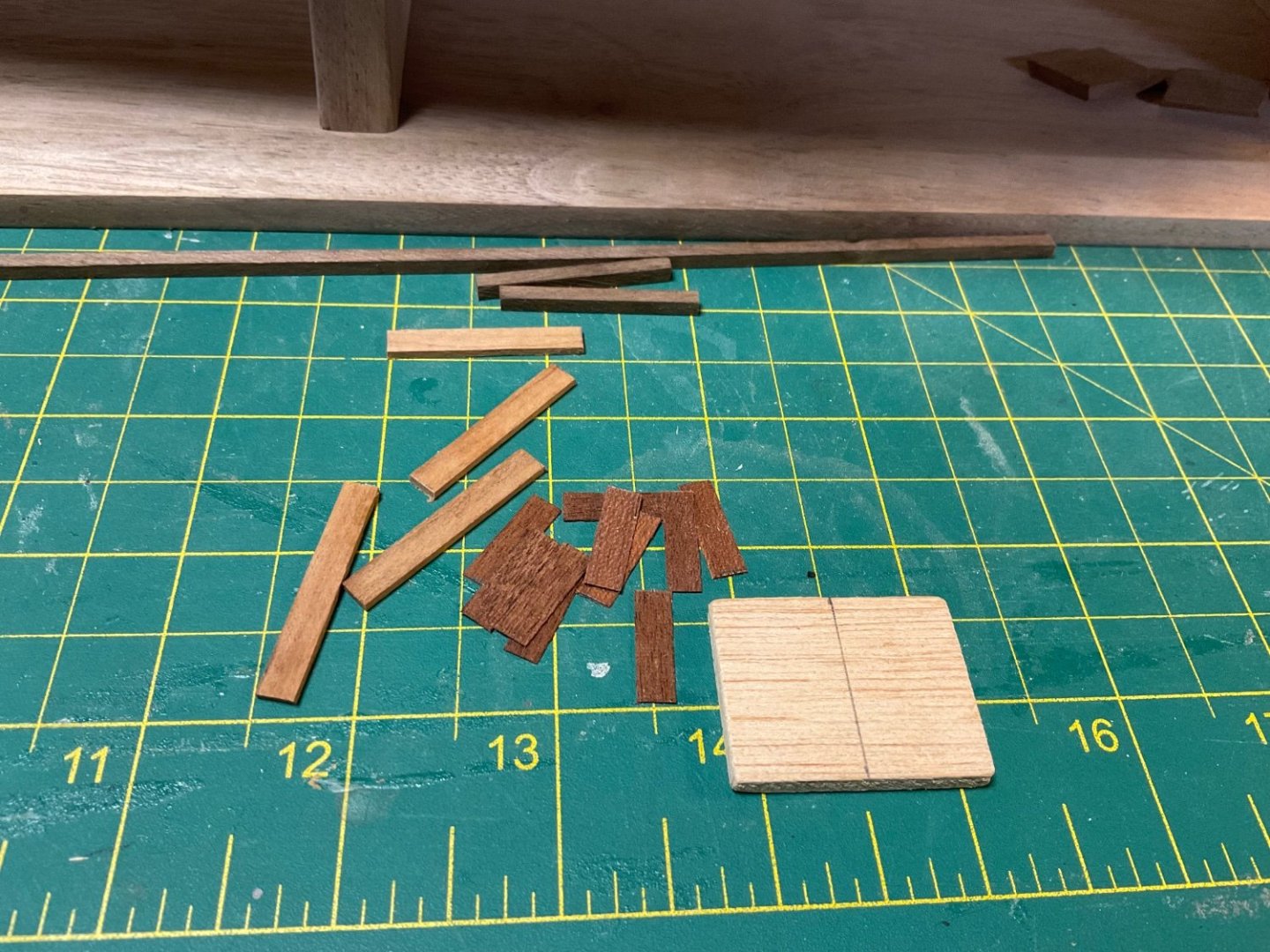
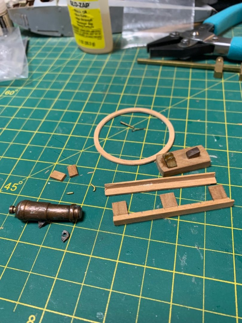
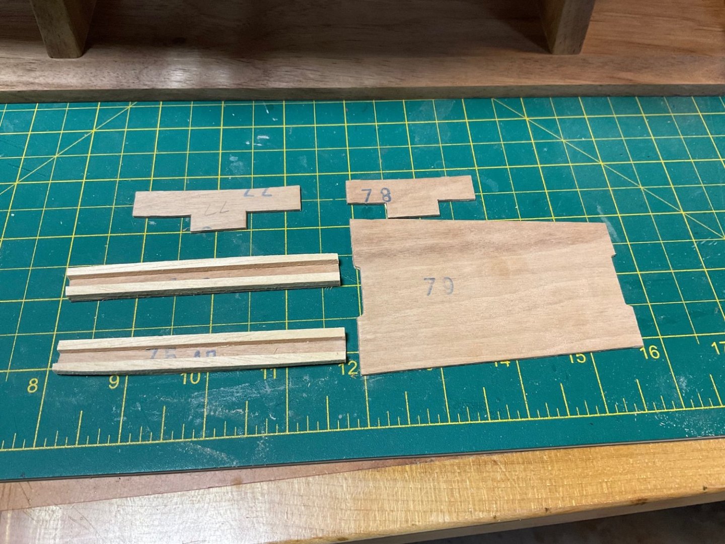
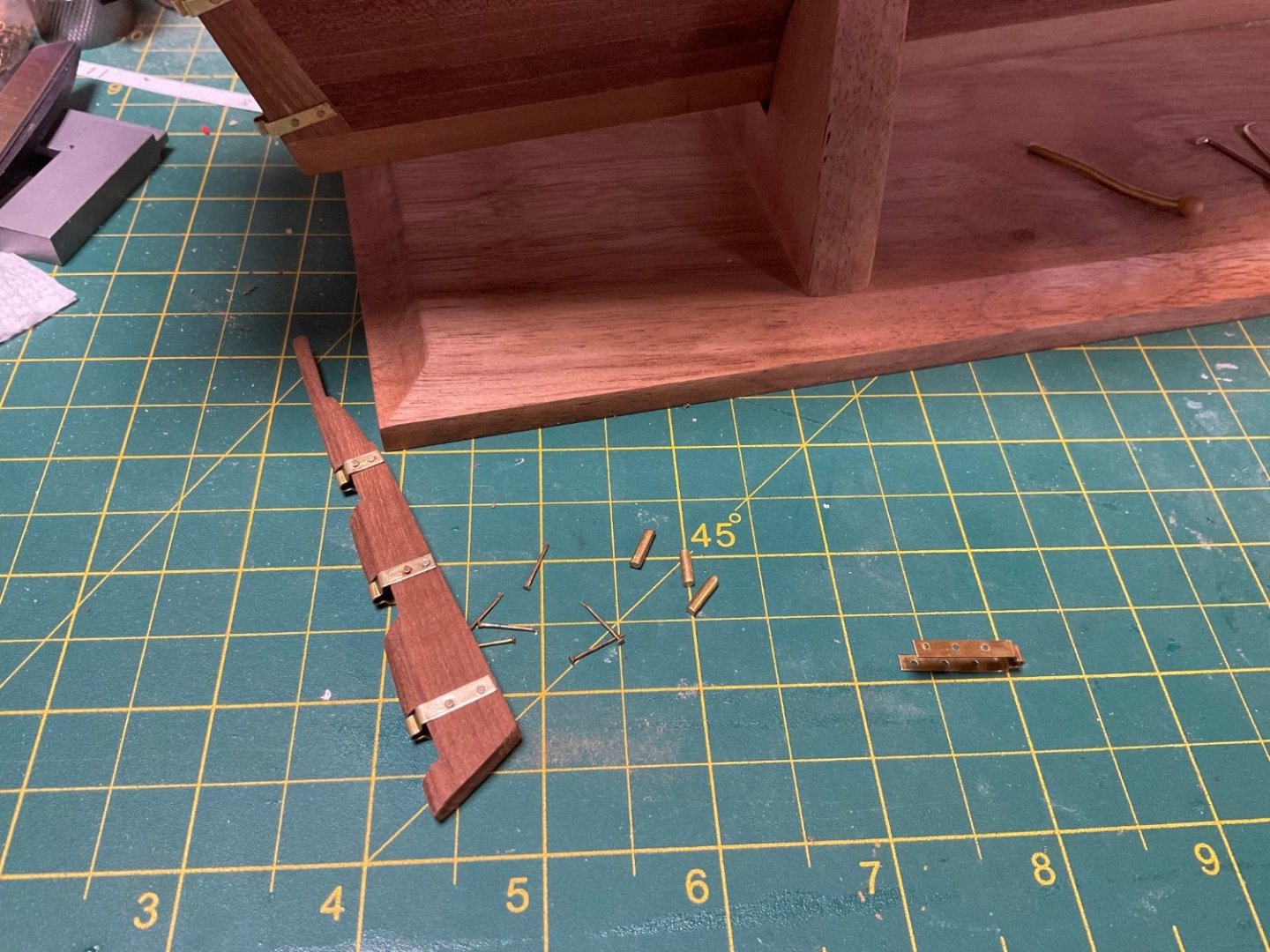
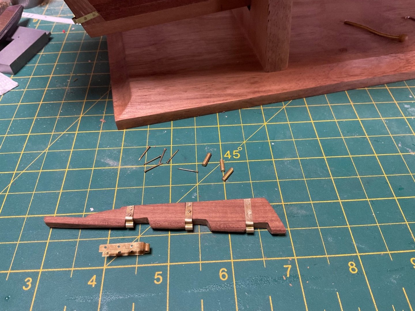
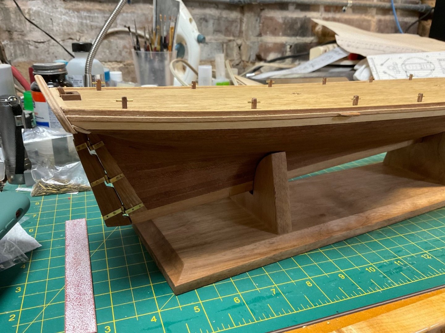
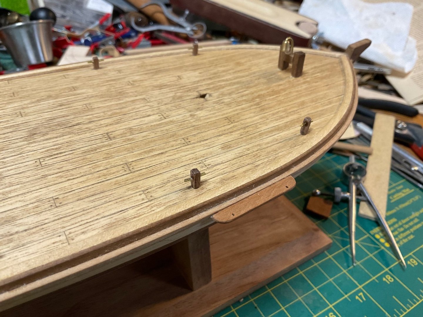
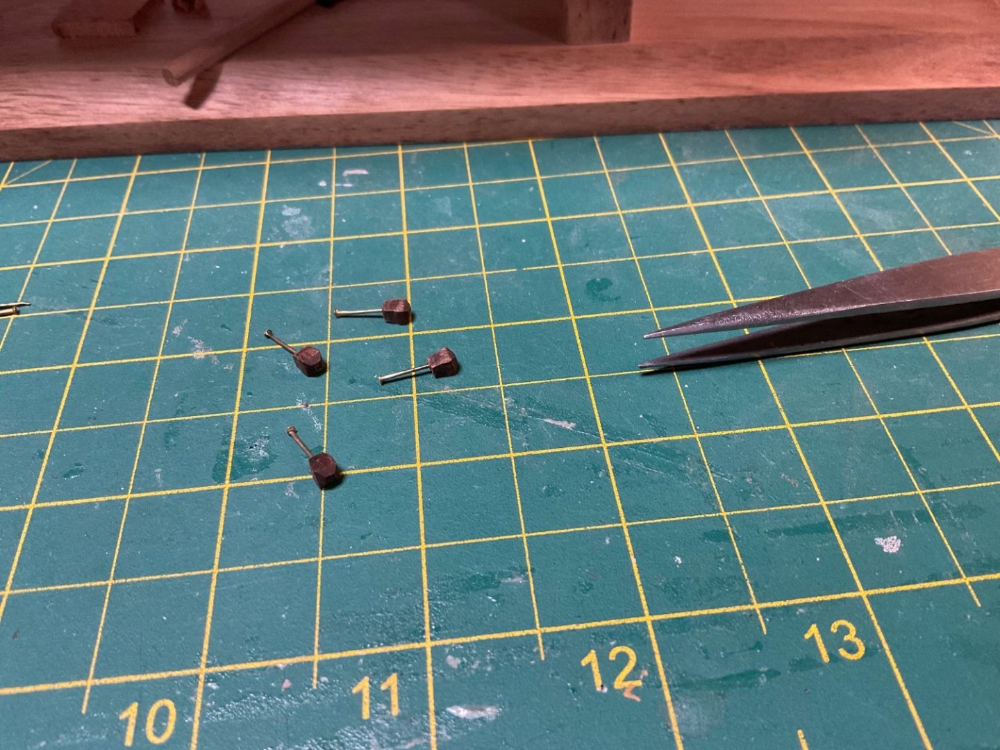
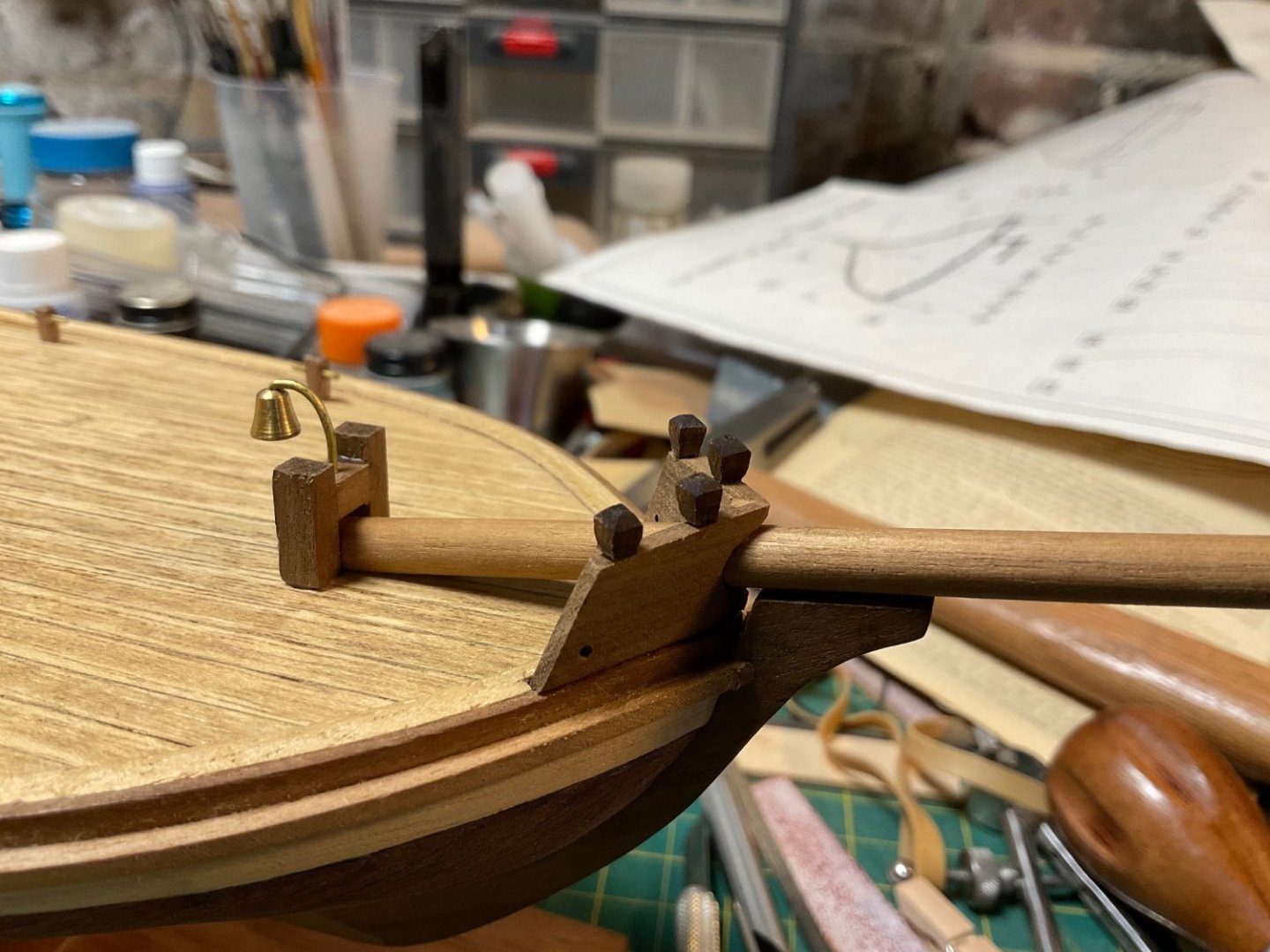
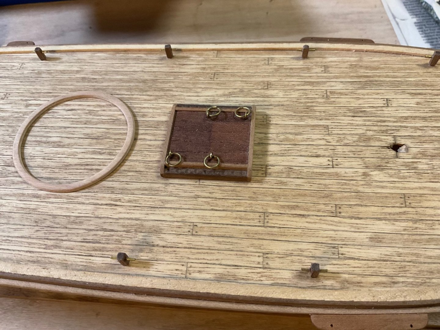
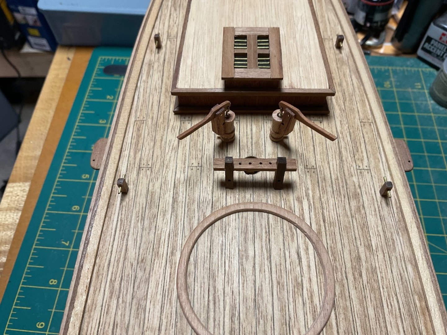
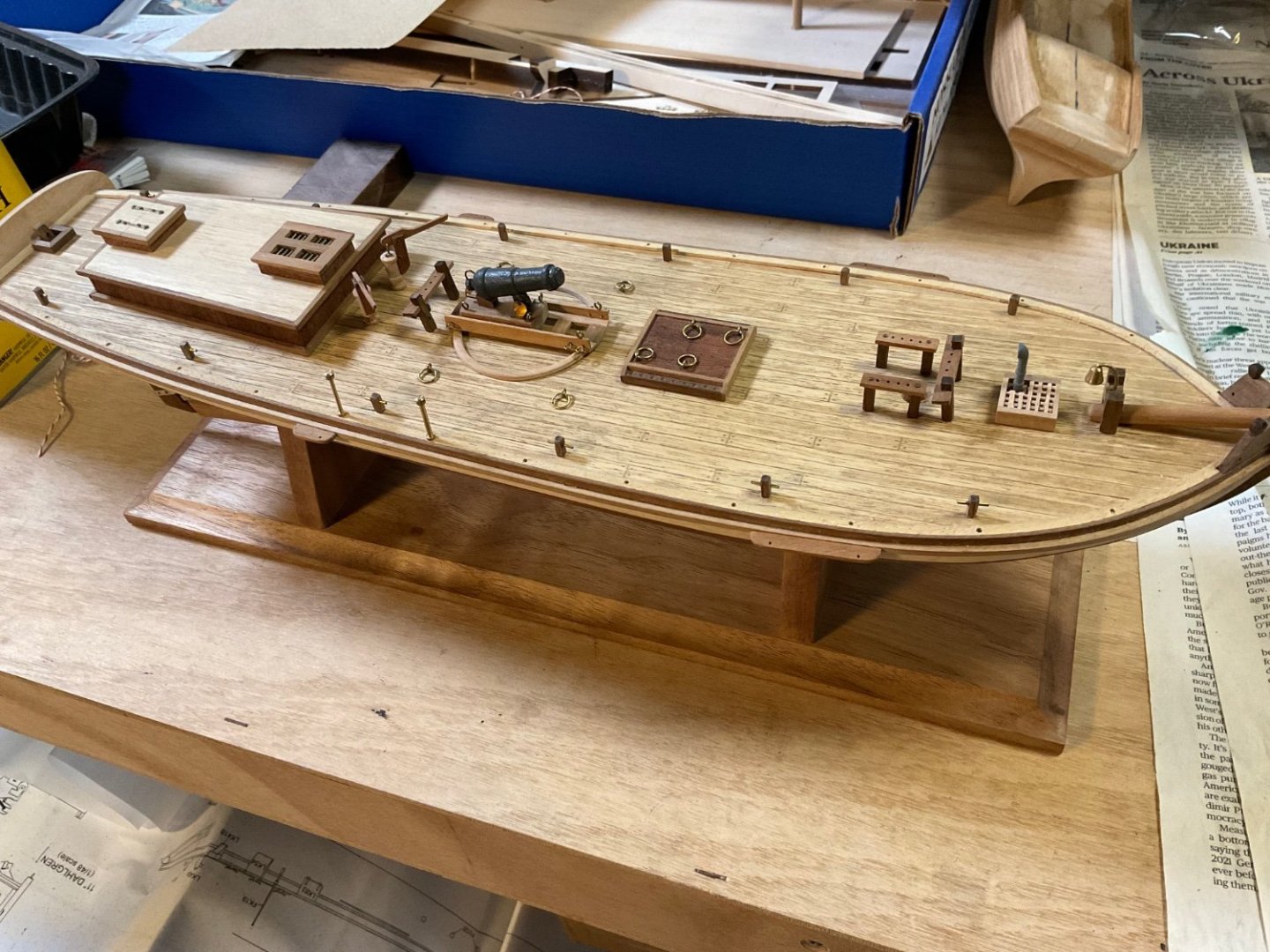
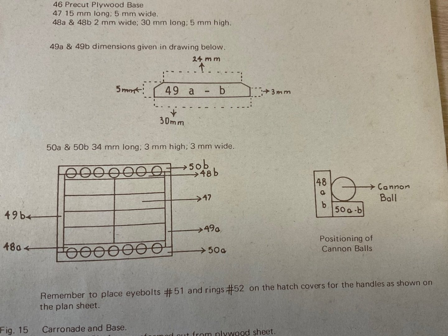
Thanks Phil, based on your info, I drilled out shallow pockets for the cannon balls. This will give them more glue surface than what the drawing showed. Some progress has been made on the deck furnishings and sub-assemblies. I put pins in the channels for added strength, otherwise, I’m sure the rigging would have pulled the channel from the hull. Here is the channel attached to the hull. Here are the parts provided for the rudder assembly: All of the straps provided were pre-drilled for bolts and were too long. I trimmed them to fit and drilled additional holes where needed. Pins were clipped shorter to simulate the bolts on the straps. I think the final rudder assembly looks decent, but very challenging to construct using the provided materials. Here are the parts provided for the vent: Vent assembled: Locker assembly: Final locker assembly on deck: Cabin assembled: Final cabin assembly: I put pins in the knighthead bits for strength, there is no way these would stay in place with glue alone: Knighthead bits attached to splash boards: Here are the parts provided for the pumps: Final pump assemblies on deck: I drilled out holes in the deck for the masts using a drill press, the plans show an 11 degree rake for the masts, this was easy to reproduce on the drill press: The cannon assembly was somewhat disastrous. The cannon barrel was in rough shape as it came, the metal was cracked and the finish had flaked off in some areas. Also, the barrel was a little bent. It also didn’t help that I dropped it a couple of times and broke pieces off. I used a file and tried to smooth it out as much as possible and used putty to fill the cracks in the barrel, then painted it cannon black. And this is where progress currently stands: Next is the rigging for the cannon. The instructions are unclear as to the proper way to rig the cannon so it should be an interesting exercise.


-
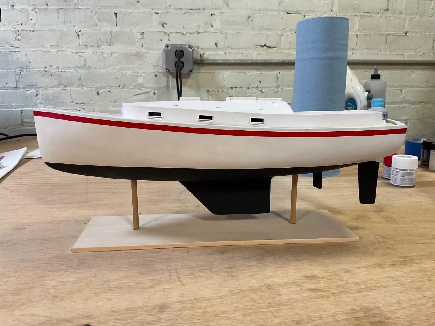
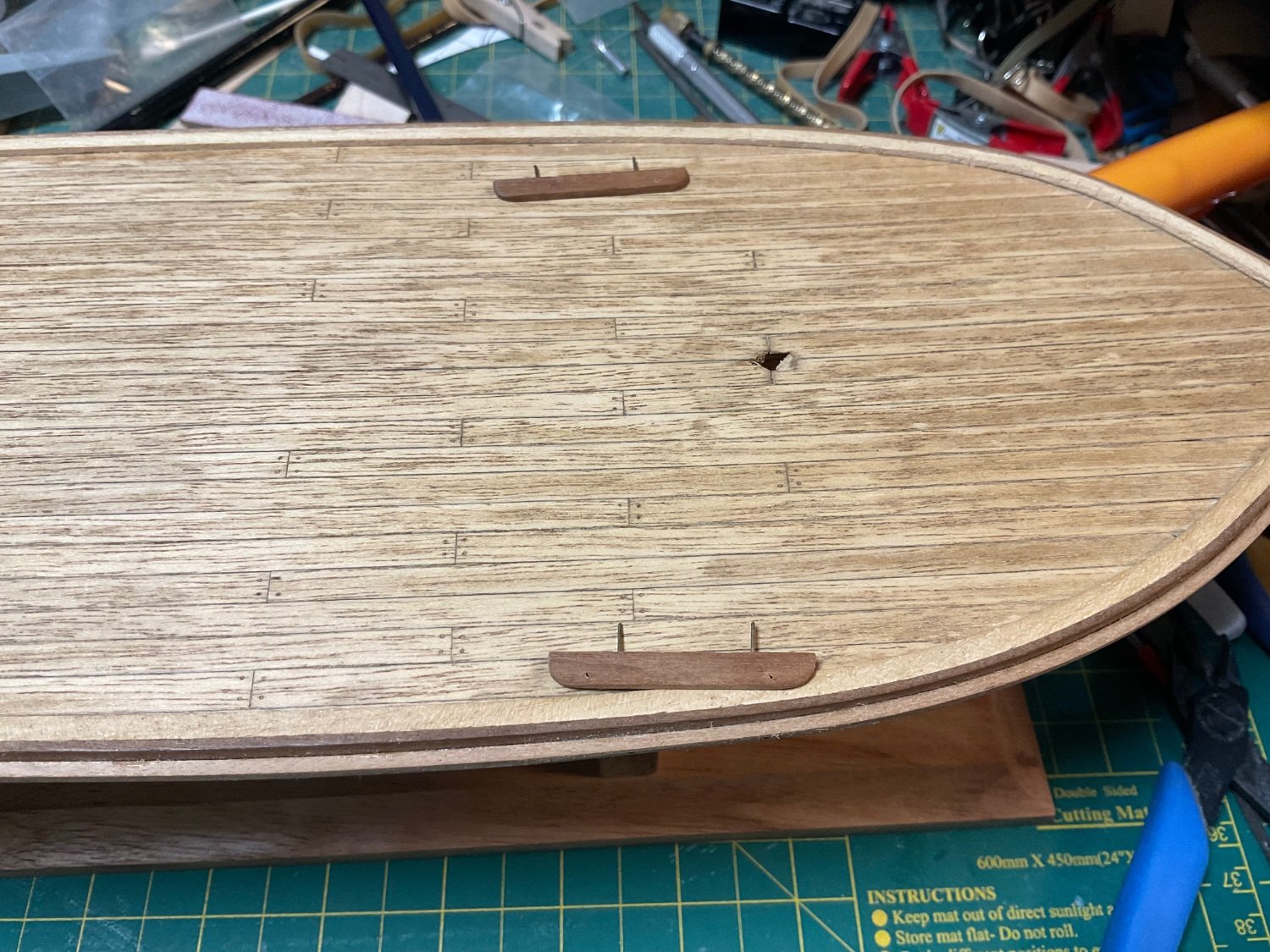
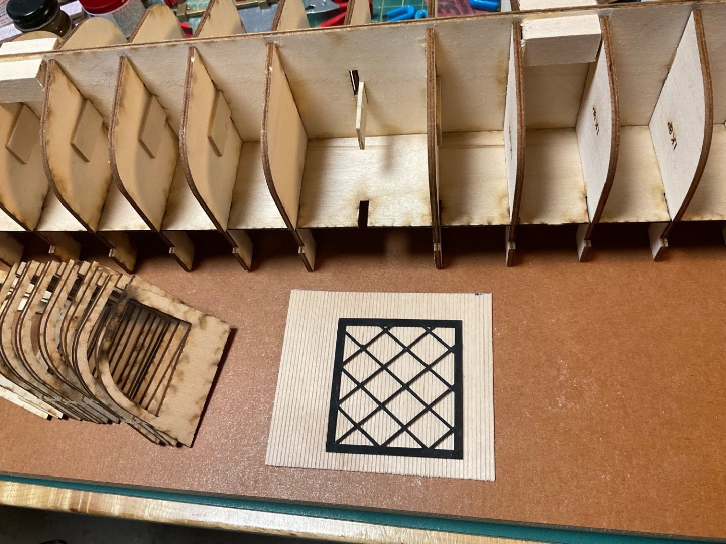
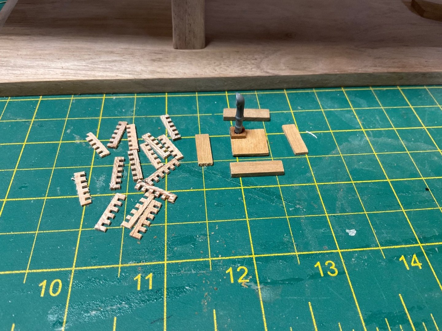
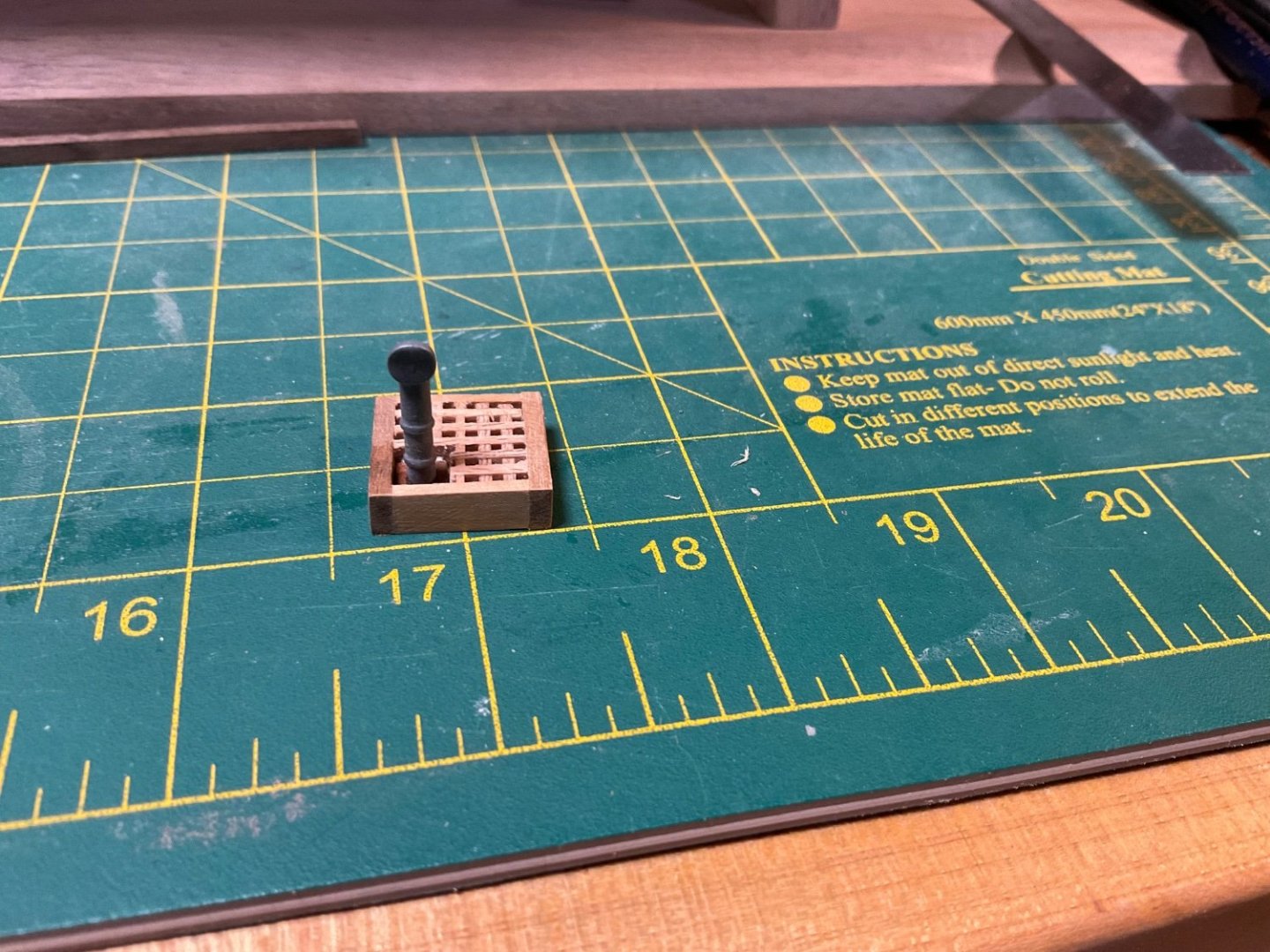
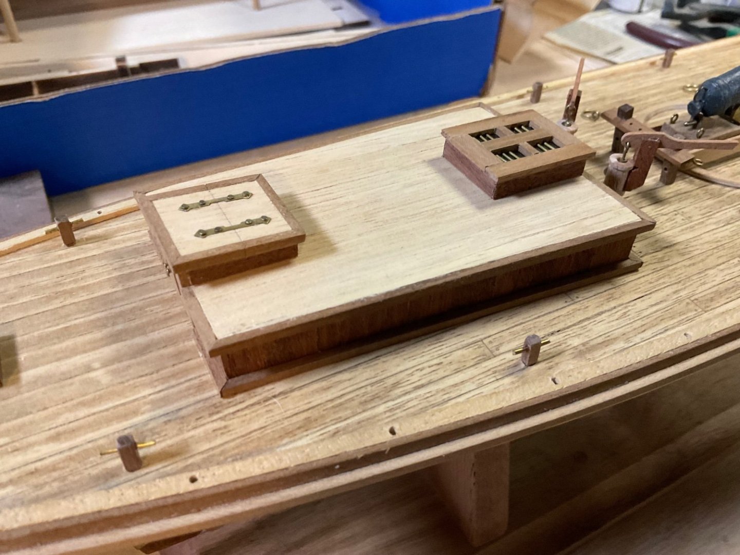
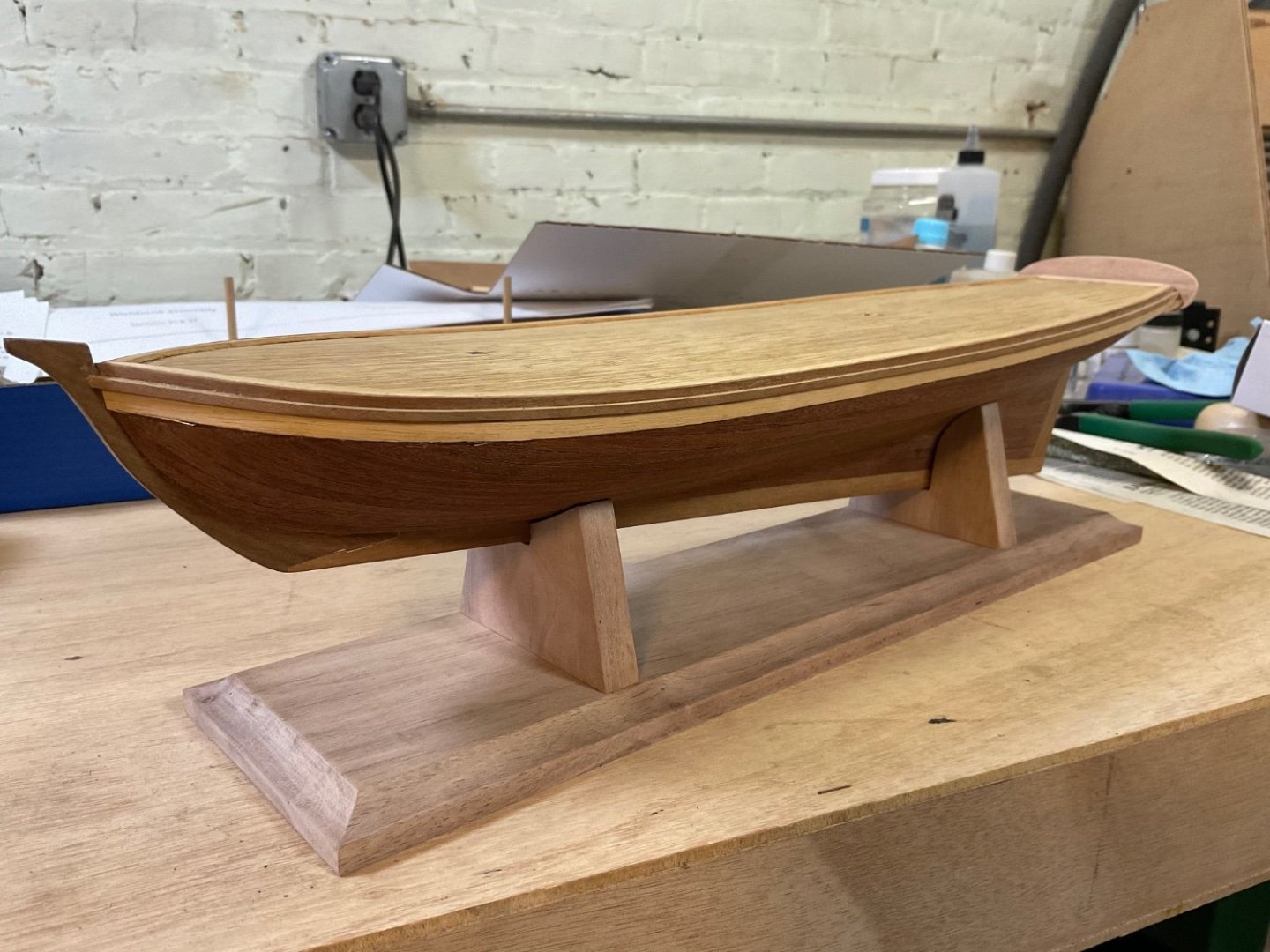
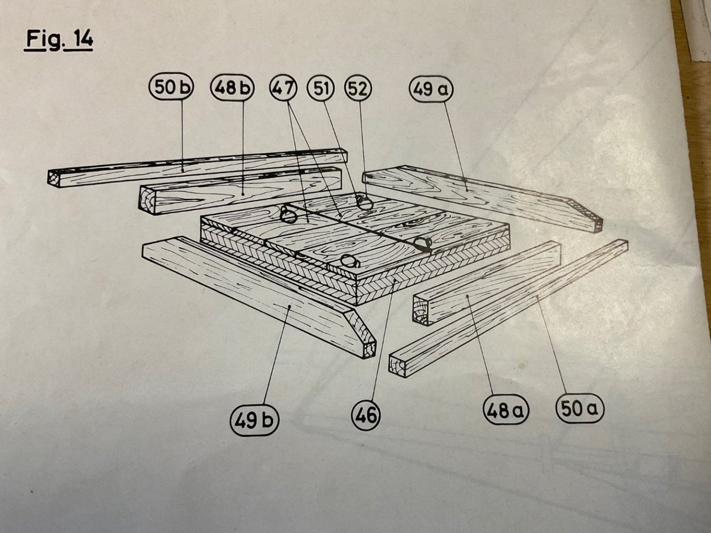
It’s been a while, but I wanted to give an update on the revenue cutter progress. This one has been on the back burner but some progress has been made. The hull veneer was applied as well as the waterway. I also built a cradle from black walnut. I started putting together some of the deck furniture but am a little confused on the construction of the hatch with cannonball storage racks. A detail in the instructions shows the cannonballs sitting on parts 50 a-b. It seems strange to me that there is nothing to secure the cannonballs to the rack. I could put a retainer board next to part 50 but this is not shown in the design or picture. What is the method for securing cannonballs in practice?
-
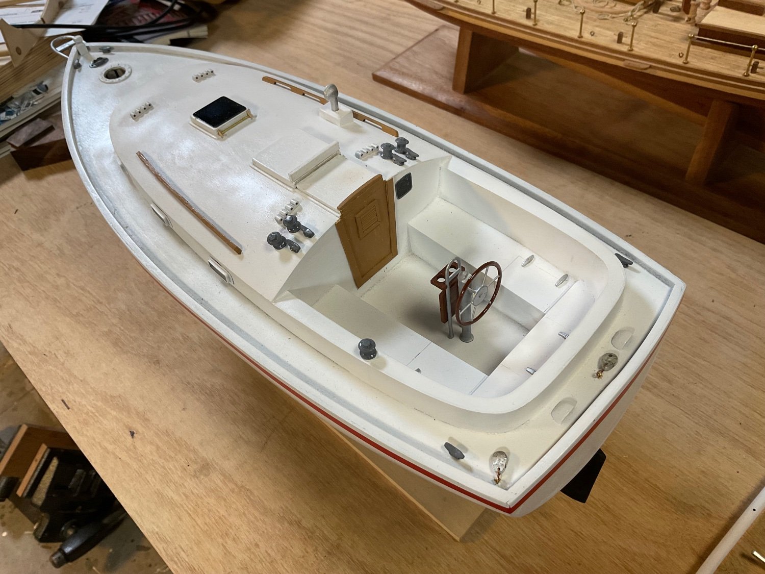
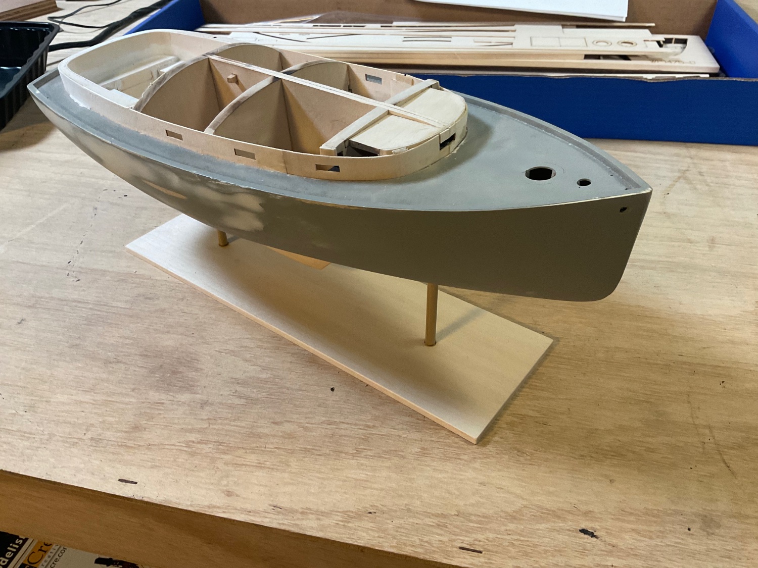
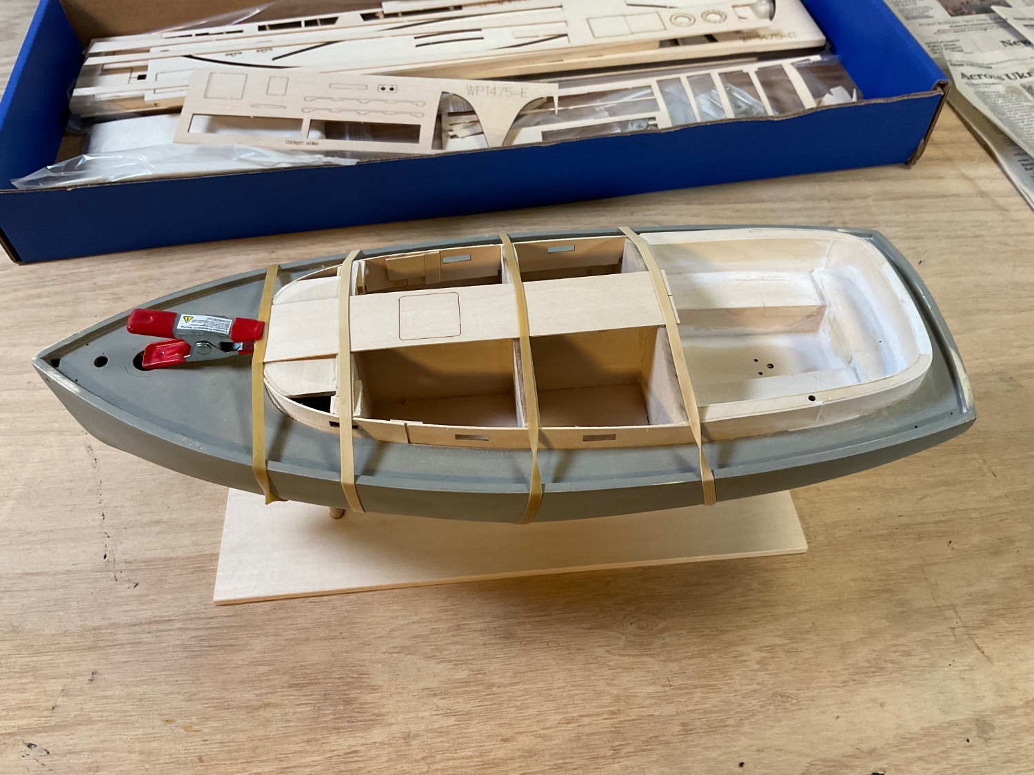
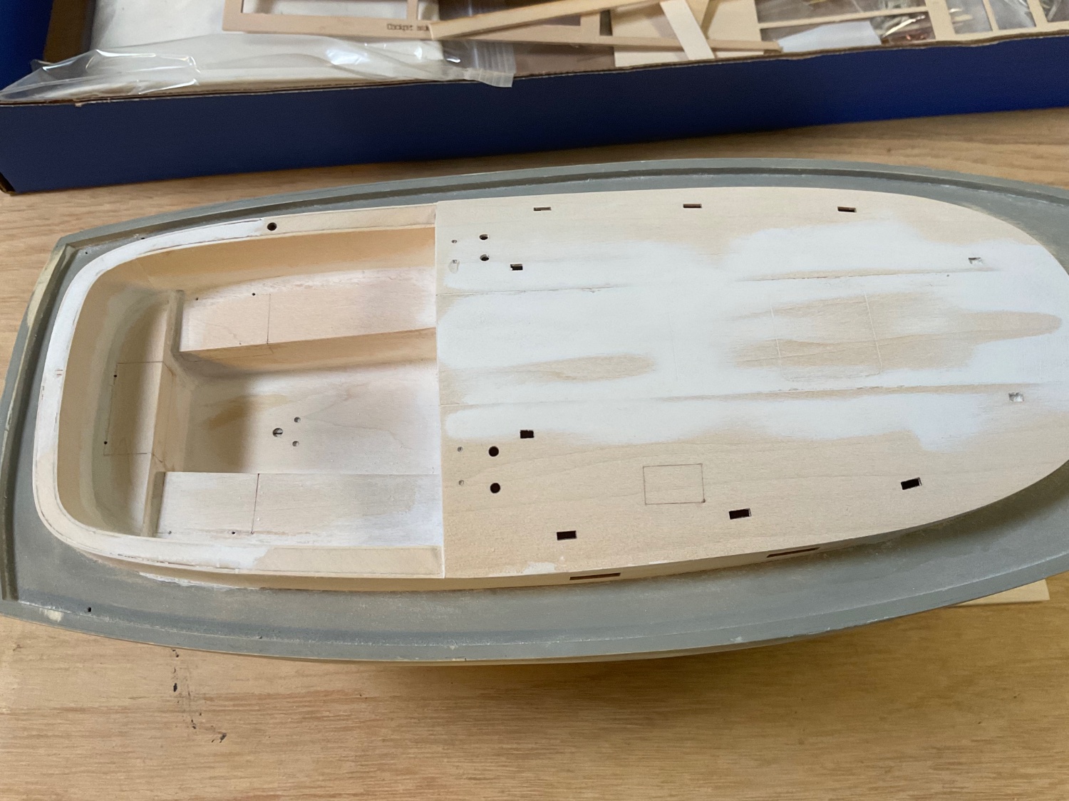
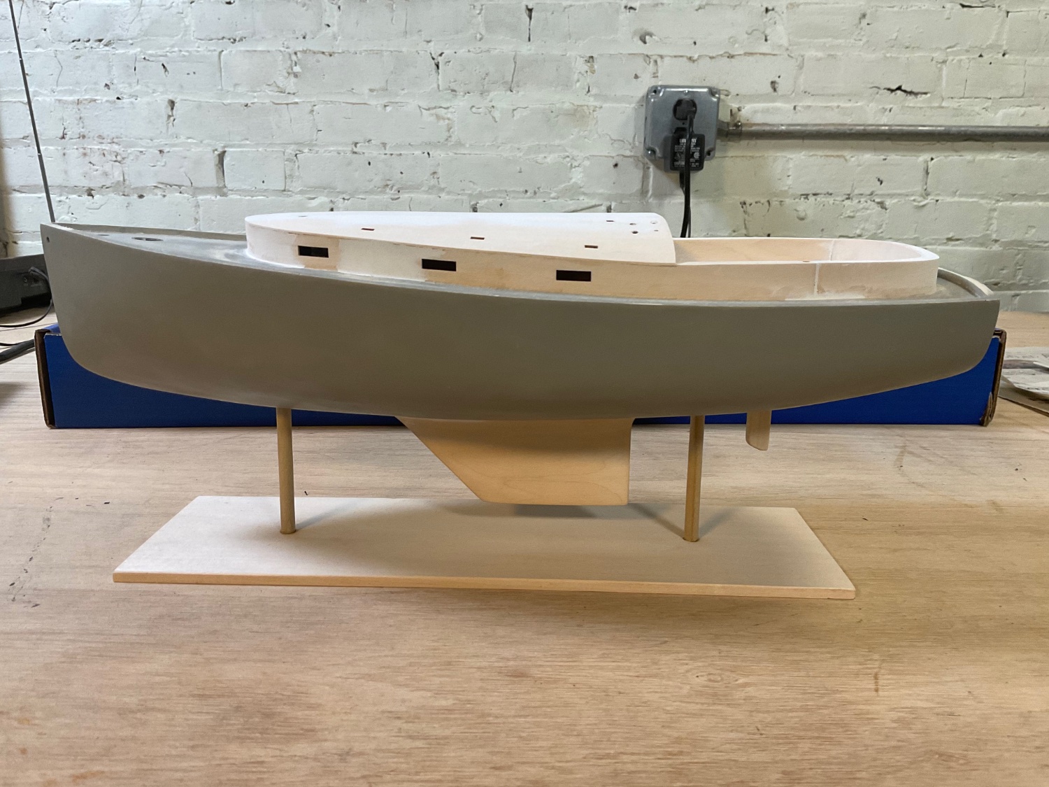
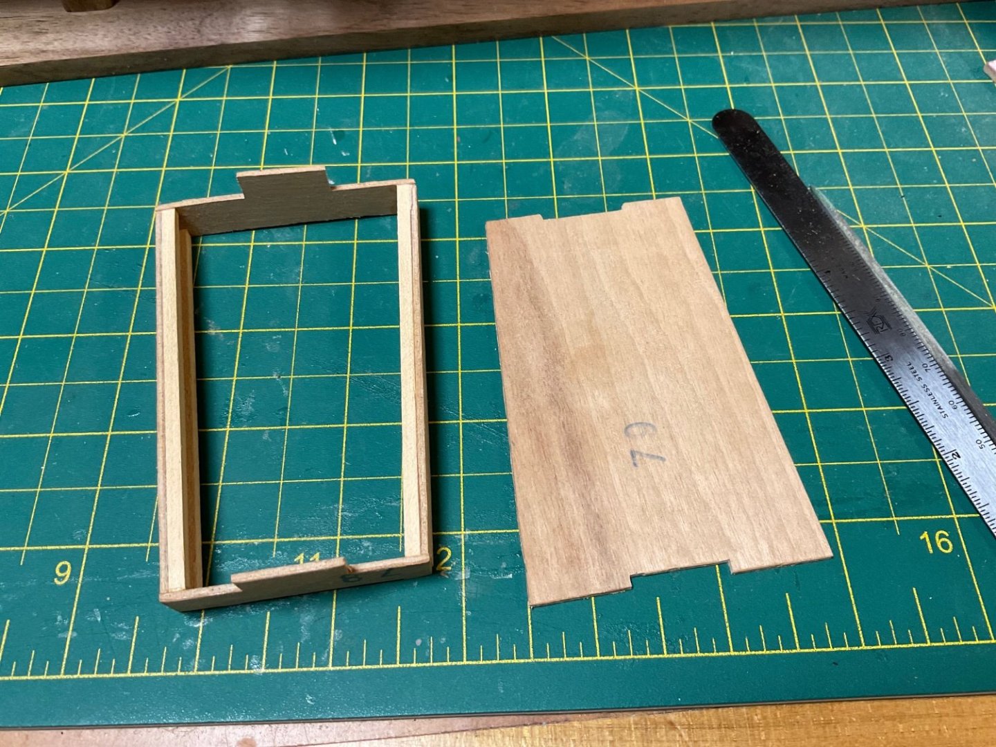
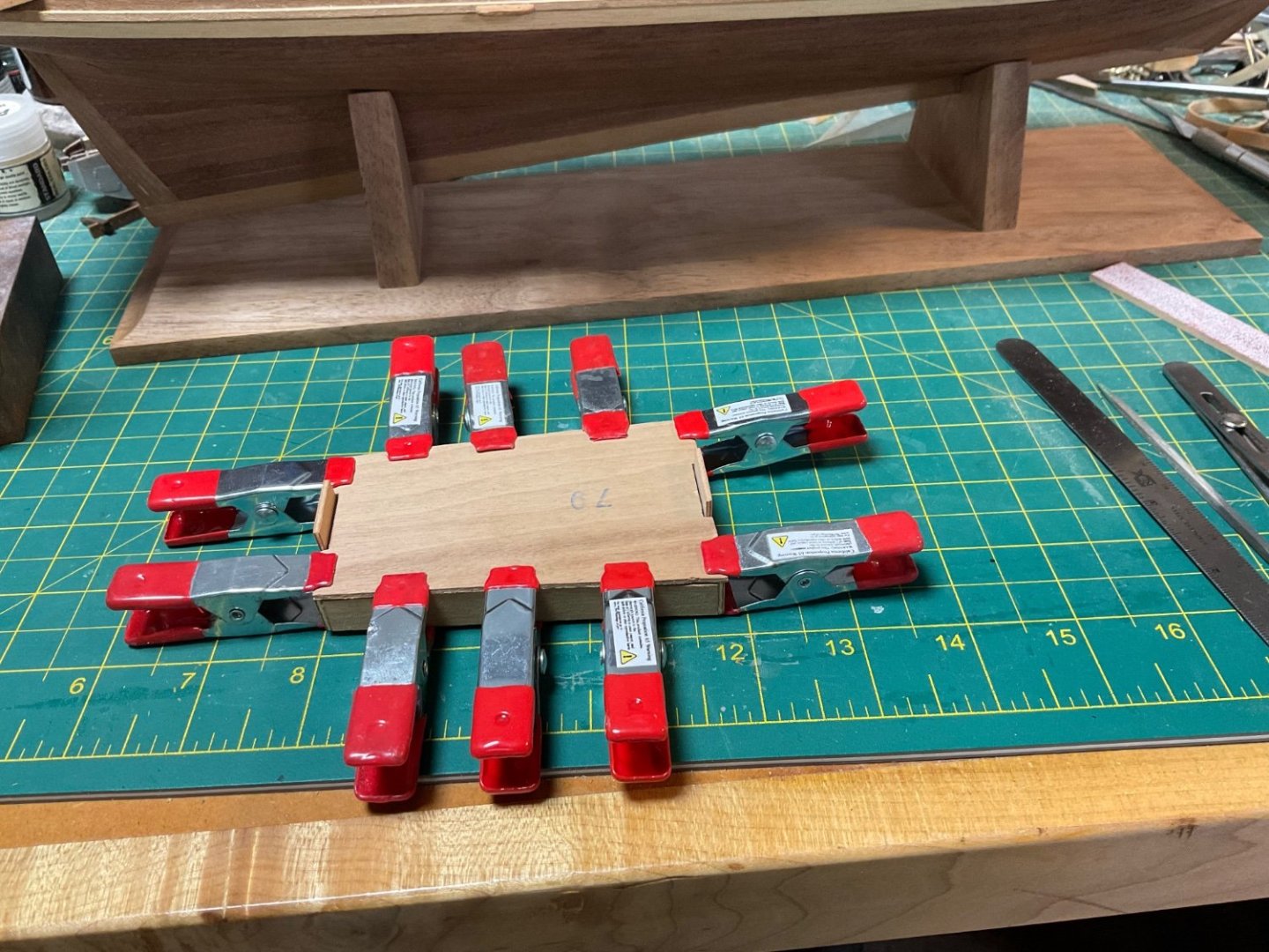
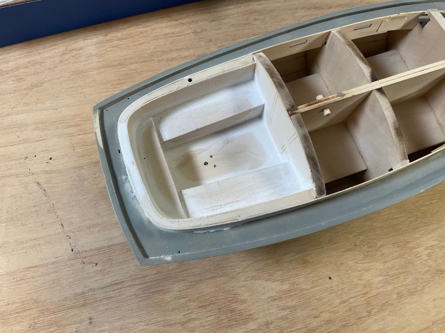
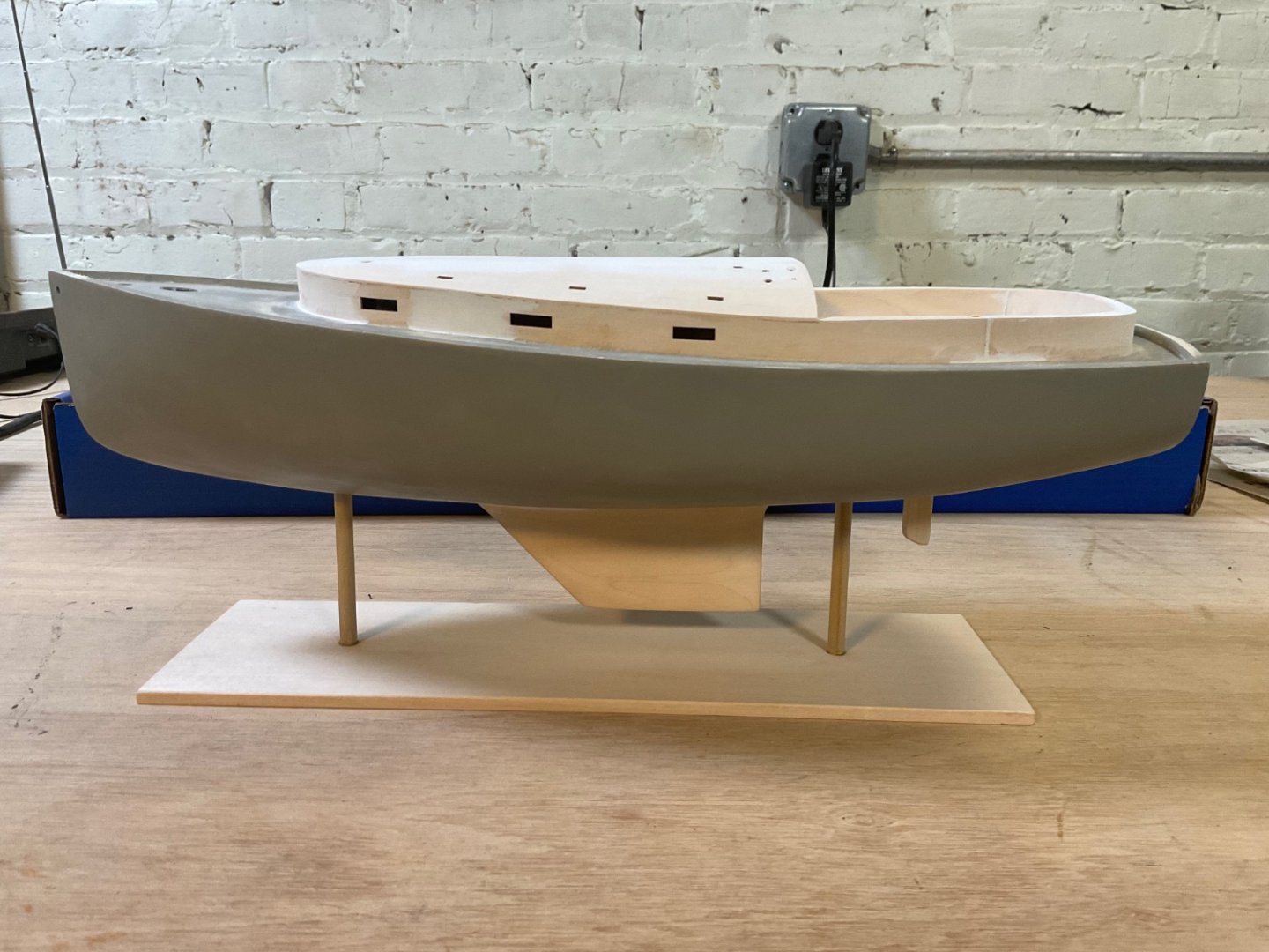
Yes, both cockpit sidewalls had to be adjusted to accommodate the hinges. The cockpit was reworked by bringing the walls out, this took a bit of trial and error of fitting pieces, adding shims where needed, and re-creating a few pieces from scrap. The cockpit and cabin sidewalls are in place now. Placement of the front cabin walls was particularly challenging as the wall pieces have to be bent around the front curve. This would have been much easier if the front wall parts were run against the grain instead of with the grain. After struggling with one side, I cut out the other side from scrap with vertical grain and had a much easier time. This could have easily been done by the manufacturer by swapping the front cabin wall pieces with the cockpit seat backs on the cut out sheet. I’m wondering if this was originally intended and just didn’t make it to the final layout. For me, there was a lot fiddling with the placement of the cabin walls until I got something that I thought looked right with the windows lined up in a row. Placement of the ceiling was rather straightforward which is composed of three pieces. I had placed the rudder earlier as instructed but it got knocked loose while installing the cockpit and cabin. My advice would be to leave installation of the rudder until after hull is glued to the base, otherwise there is a good chance it will get knocked or broken off during the construction of the cabin and cockpit. Fortunately, mine was only knocked loose and can be glued back in place.


- 27 replies
-
- 8
-
-
- Nonsuch
- Model Shipways
- (and 1 more)