HOLIDAY DONATION DRIVE - SUPPORT MSW - DO YOUR PART TO KEEP THIS GREAT FORUM GOING! (Only 24 donations so far out of 49,000 members - C'mon guys!)
×


Jaager
-
Posts
3,084 -
Joined
-
Last visited
Content Type
Profiles
Forums
Gallery
Events
Everything posted by Jaager
-
From the book: The Restoration of the Smack Emma C. Berry at Mystic Seaport, 1969-1971 Paperback – June 1, 1973 by Willits D. Ansel (Author) out of print, Amazon only lists one copy - for $200 - I hope that a single chapter fits within the fair use doctrine.
-
First, the old articles about the smack that I have listed in my database: EMMA C BERRY BUILDING STERLING MODELS' KIFF.MARYPAT MODEL SHIP BUILDER 1982 18 4-8 KIT SCHOONER POF B SCHOONER EMMA C BERRY ON R/C DULLY,FRANK E JR MODEL SHIP BUILDER 1994 90 4-11 KIT SAIL R/C SCHOONER A SCHOONER EMMA C BERRY PT.2 DULLY,FRANK E JR MODEL SHIP BUILDER 1994 91 24-29 SCHOONER 20TH KIT R/C B
-
The Amazon product: a sucker bet, a complete waste of money, likely to cause near infinite frustration. As for a metal lathe - or a mill - experience and observation about the value to you should you pull either of those triggers is that: If you have to ask, then you very likely do not need one. Doing a reference chase on books about miniature lathes and mills should serve you well. No one book is likely to provide the complete answer and the mixture, filtration and synthesis of more than one to guide your decision is to your advantage.
-
 Being at that same point, I see two conflicting factors in play. It is much easier to fare the bow without the stem. Rather than having a notch where the stemson would be, I opted for a stemson that is flush with the bow timbers. But with it being all that is there, the danger and likely outcome is the stemson will be rounded over and not provide a sufficient landing for the stem. Thinking on it, the wise choice is to attach a temporary sacrificial piece of wood where the stem will be. Let it take all of the abuse. I think a bent thicker ribbon of wood may do the trick. I am not being able to resolve a dowel - not dowel conflict as regards how to attach the stem assembly. I do not see a need to fix the stem until I am ready to attach the wale, so I can put it off.
 -
It is sobering to see the sorts of tools that were available back then. I am sure that many of the specific choices were determined by the magazine's advertising department. I began this about ten years later and it helps make clear why I made some of the choices that I did. Choices that my retrospectascope shows were far less than ideal. I remember that a Shopsmith was considered a big deal by some back then. I have never seen one in person, but I worked for someone who had one. My impression from back then is that it did a fairly wide variety of jobs. None all that well, and the time necessary to reconfigure it was significant as well as being a source of frustration. I suspect that one of its gifts was as an inspiration for later designers of single purpose machines with a reasonable footprint. A three wheel bandsaw is an awful, awful design, I wonder if their existence was because the two wheel models of the time were huge and expensive monsters? One machine that we do not have at a modeler's scale size is a crosscut with horizontal rather than chop blade movement. When needed, it would be handy to have. But the reality is that the few times that it would be needed could never justify either the money spent for it or the bench space it would take up. In photo #22 - the philosophy behind the function of the Belsaw machine is just as valid today. It is to be grateful that we have better ways to do it now.
-
MPJA.com sells a DC selectable power supply $20 AliExpress has a wide selection of small DC motors some with Jacobs chucks and probably some with collet chucks for $20 or less Even the old loss leader small DC drill that Harbor Freight used to sell - that was hopeless with the supplied DC transformer - actually does some work with the selectable power supply. Worse comes to worse, even a General pin vise with the heel swivel and 4 sizes of collets (2 double ended) would probably be better than any small pus pull drill. We has a long round table discussion about pin vises here, not that long ago. It may be work a read.
-
I don't even know what I don't know about motors and electronics, but I am of the thought that most Dremel machines are designed to work in the 5,000 - 30,000 RPM range. I have an old single speed tool of early 1970's vintage and I bought a Dremel solid state speed control to use with it, but I do not think that 300 RPM would be possible - not enough power to do any work. I think that the whole series is designed around flash rather than actually doing any real work at whatever speed is selected. The chuck that fits 1/8" shafts may be a problem, but a DC motor - there are many sizes and most are low cost - a bench top DC power supply that is 3 -4.5 -6 -7.5 -9 -12 Volts @ 2000mA is <$20 if a lot of torque is not needed and 300 RPM may be possible there. I now have a Foredom TX and it has a range of 500 - 15,000 - it is a much superior tool for rotary work. It is supposed to provide full power at the low speed as well as the high speed. If it is just ship modeling that you will be doing, It will be difficult to find enough work for any rotary tool to justify a major capital outlay,
-
Staining rigging to match the miniature model
Jaager replied to BrankoSNY's topic in Masting, rigging and sails
Knee jerk response - probably not. For wood, aqueous aniline dyes are stated to penetrate wood more deeply than alcohol based dyes. The water will raise wood grain -at least on first exposure - and alcohol does not. At full size furniture scale, the depth of dye penetration is probably an important factor. At the scale of a wooden ship model, I strongly suspect that any difference between alcohol and water based dye is too slight to matter. This would make alcohol based dye a preferred agent for a model being "painted" with wood. For fabric fibers, the density is magnitudes less than any wood, so alcohol should penetrate with no problem. As far as I know, no low molecular weight alcohol has any negative effects on natural plant fibers. Just keep Clorox away from silk. In my shipyard PVA is the only man-made synthetic material that is allowed. (I have more than enough linen yarn, cotton thread, and silk.) I have no idea what would color Nylon, polyester, polypropylene, or Dacron or whatever synthetic is now infesting current model rope stocks. -
Staining rigging to match the miniature model
Jaager replied to BrankoSNY's topic in Masting, rigging and sails
Mark is correct and on target. Using tea or coffee is very old tech. It is in some of the very old 'how to build a ship model' books and I am guessing early articles in the NRJ. The organic acids in the extract make it an ill advised way to simulate Pine tar. It may or may not be a significant risk, but why introduce potentially destructive factors when there is no need. Liberon and others make a pH neutral dye - it comes as crystals - an extract from Walnut husks - the solvent is water. The shade and intensity can be controlled by the concentration of crystals in water. Also a possible dye agent can be made from mixing red and black stamp pad refill liquid. There is always Rite. Wood dye can be diluted. We also had a recent kendo fight about how close to black was standing rigging before the petrol era (Drake's well - 1859 - PA, USA) but I still vote against using the 000, 000, 000 black common with kits. Dark, dark, dark walnut is not so kitschy. It was fairly convincing that running rigging should be some shade of straw color. -
First off, I like to term 1:48 = museum scale - at least for for the wooden vessels up to 1860. The vast majority of plans from the pre 1860 eras are 1:48 and most of the models that are contemporary with the original vessels are also 1:48. It makes for a convenient base scale for description and comparison with other scales. 1:50 - at first seems like it is the same as 1:48 - but the difference is significant. While any one dimension is 0.96 less at 1:50, model is a 3D entity and the over all model is actually 90% the size of museum scale 1:64 - is 42% the size of museum scale.. Each dimension is 0.75 less. 1:60 - is ~50% the size of museum scale. Each dimension is 0.80 less. Gaetan's 1:24 model is 2.0 larger each dimension, but the model is 8 times larger than museum. He had to use 8 times as much lumber. 1:96 - is 0.5 for each dimension but the model is 0.125 as large as museum scale. 1:72 - 0.67 per but the model is 0.30 the size of museum scale. 1:76 - 0.63 per - the model is 0.25 the size of museum scale 1:120 - 0.4 per - 0.064 the volume. I explored this for the first rate St. Philippe - a first rate @ 1:60 is imposing, 1:120 would be less intrusive to display, but the carvings would be a nightmare. !:192 0.25 per - 0.015 the volume - I think this is the preferred scale of our published miniaturist artists. At first glance - 1/4 the size does not seem so bad, but when it is actually fabricating something that 1.5% of museum scale - just what they have accomplished is awe-inspiring.
-
Totally apart from the kit fan base aspect, I will approach this from a curmudgeon-like view or a sober view: Buying a backup kit in your place in this path: Has two positives - It helps assuage your present enthusiasm. Enthusiasm that is necessary to do this as a hobby. The effect has a very short half-life. If inflation takes hold, it may save you money in the future. Especially if you do not otherwise put the money that you would spend on a kit, in an escrow account that keeps up with inflation - something that the system is geared to make difficult. And negatives - As you progress with your current model, your knowledge of this field should expand. Your interest and choice of subjects may progress beyond what you consider. In general, the necessary enthusiasm and drive to do this tends to cycle. Most beginners probably do not continue beyond the first down cycle. A backup kit will not maintain enthusiasm. It will be money lost. Lucky it would be to recover 50% on Ebay. You should probably setup a stealth escrow account for this and continue to in filter funds - if you are not a solo. The same sort of standard for any tools: If you do not need a tool now for a particular task, If you have to ask about it, If you do not have more money than sense, you should probably wait to buy it until the need is obvious.
-
I think it is in Underhill, that after planking the hull, he 'flooded the bilges with varnish'. I am fairly sure that at the time it was written, varnish was generally taken to be essentially "boiled" linseed oil in mineral spirits. It was probably a 'one off, seems like a good idea' choice. Not at all an experiment with controls. At the time, most of those writing how-to books were few in number, in isolation as far as consensus about what were optimal practices for stability over time. The closest to that I have seen to objective procedure are the USN museum standards for models that they would purchase. I am not sure that any finish will be 100% successful at preventing the hull wood from equilibration with the temperature, O2, and water vapor of its environment. Clear coating a closed interior may or may not have any practical benefit. But one definite negative would be if you coat a place where a subsequent wood to wood bond would be. PVA bonds by intercalating its synthetic hyphae onto a microscopically rough surface and into micro pores that all wood has. Filling the pores and smoothing the surface with a clear finish, or sanding finer than 220 tends to defeat the bonding process. Coming at this from a POF - with no windows cut into the hull - point of view - if you intend to shellac an interior space before it is closed - I recommend that any site where a PVA bond is yet to be have a masking material there before the shellac is applied. A really tedious and no fun at all sort of prep work and worse, clean up after. Then, if your OCD about this is intense enough: what to do about the sides and bottoms of the deck beams and the underside of the deck planking between the beams? It would take the skill of a fiber optic surgeon to get at it after assembly. If done prior, this adds significant time and work to assembly. To be logical, worry about failing due to environmental forces demands another factor. Certainly if it is a properly precise wood to wood bond that was clamped with enough pressure to yield a close surface to surface distance. The polymer chain length should not too long, for a strong bond to form. This other factor is what I call a belt and suspenders bond. That is, the bond be both chemical and physical. The physical part is a dowel at every bond. The dowel, if visible, should have an in scale diameter. Pulling bamboo thru a draw plate - especially in the high #70's range is difficult and the yield is low. It is grad school level - 15% finish - rather than med school level - >95% - if you get in you will finish unless you work at failing. The bottom line - for a PVA wood to wood bond - always have it raw wood to raw wood. If you use an agent that allows smooth surface to smooth surface adhesion ( epoxy (?) or CA ("the horror, the horror") ) the worry goes up stream. The weak point is the clear finish to wood bond. And no finish ever flakes off? addendum: In the shower just now, I remembered another option: For a clear coat for a part of the hull that will never been seen again - give a thought to brushing lacquer. It is visibly thick, drys in 2 hours, has been around long enough to show that it lasts. Too shiny to use where it can be seen. It is out of scale thick, also. No spray version - small enough to spray is small enough to breathe - any mitigation will never be as good as never making it airborne to begin with.
-
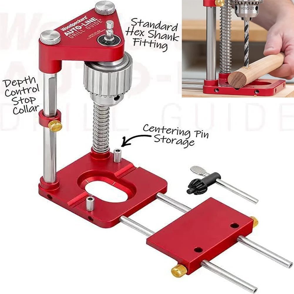
A hand drill or most any motor that connects to a standard hex shaft, I wonder how the chuck that comes with it is attached? Perhaps a different chuck could replace it?
-
I came across this on Ali Express. I am reasonably certain that this would be a source of endless frustration and trouble, but it is low cost: Although this is a bit of drift from the topic at hand, months before, while scouting an XY table to possibly fix to my Foredom drill press attachment, I came across this device ( for a grinder tool) on Ali Express. Even if it is possible to mount a Foredom hand piece in way that is secure and reproducible in precision: as superficially cool as it looks, I cannot come up with a job that it would do that is relevant to ship model building. Am I missing something? Doing an inferior job at replicating a HF chop saw is about it.

-
Schooner plank length
Jaager replied to alross2's topic in Building, Framing, Planking and plating a ships hull and deck
The ASA rules up to 1903 call for both deck planks and hull planks to be "the greatest length possible". I suspect that by the turn of the 20th century, a significant portion of the old growth timber had been felled in eastern North America.. The mid 19th century US Navy wanted deck planks to be 40 feet long. The favored species was (I think) Yellow Pine. It is not a wood that is seen much today - maybe some is recycled - everything usable was harvested - it is a species that is rock hard, it liked to turn a nail - not at all a soft Softwood. I think that some has been replanted, but without consulting my Silviculture references, I suspect a species that hard and tall would be fairly slow growing. As desirable as it would be, I suspect that a southern tree farmer would have to plant Yellow Pine for his grandchildren or great grandchildren to harvest. I sort of doubt that Georgia Pacific would be up for doing it. So I think it would come down to what was available, as to length. Your guess would be as good as mine, on what it would be. It was probably even more restricted in Northern and Western Europe. My shipyard will use planks 25-40 feet long. But for an individual ship, a single length, instead of random. If a particular strake would need a short piece at either end, the intent is to cheat and use a longer board instead of having a stub. It is important to follow the butt stagger rules. After seeing so much of the opposite here, the goal is to have the butts not so obvious to avoid the busy look. The deck is not supposed to be a star. My yard inspectors mentally register the words: tacky, boring, naive, distracting, inauthentic on viewing a job done like that. It is also to wonder about the logic behind having obvious and contrasting trunnels just at the butts and not also at every beam.? In any case, trunnels should not be a contrasting shade. -
There is another option in the bench size drill press: There is a drill press mount for the Foredom flex shaft machines. The accessory is far from flimsy. The motor options are for: high speed/low torque, low speed/high torque, medium speed/high power/high torque. The hand piece options allow for either chuck or collet models to fit the drill press unit. The bearings are probably up to doing any wood milling and there seems to be slots to mount an XY table - but the excursion does not seem to be heroic. This is far from an economical option, but it is sort of a one machine does a lot sort of choice for someone who has not already made serious investment in a power tool collection. As well as the drill and cutting tool function, and the fixed the drill press, there is a right angle grinder, plus router table, clamp in a vise and small belt sanding functions .
-
Being that this is a Scandinavian lapstrake vessel, it has a long line behind it. Is there not physical evidence of antecedent clinker methods from the 800-900's? The outside limits for land length could reside there. I would bet that a concerted effort was made to maintain a link with that past in how this later vessel was designed and built.
-
I have almost zero knowledge about this part of Greek history, but how well does this guess fit? These ships were "surplus" warships supplied by western powers who were keen on causing as much mischief as possible to the Ottoman Empire? If this is the case, exact or a close approximation of the actual plans or similar ones can be had from West European and maybe North American archives? The mismatch of guns would be predictable if my guess is correct. At least the above vessels are the practical workhorses of their era, They could actually do a job. The liners of that time were a total waste of resources, over sized, and ugly. These vessels were sleek and lean and most were probably fast sailing.
-
I have not seen the term before, but on an open boat, the painter is a section of rope at the bow that is used to tie it to the back of the ship - or whatever else is towing it. It supplies a metaphor? for removing someone from your support: " cutting the painter". To fit that name, I would guess that the chain is a relatively short length with the distant end not attached to anything - until it is used to temporarily secure an anchor or boat. Looking at your deadeyes, I wonder if a two part strop would work? 1- a belt that wraps around the body with ends that meet at the bottom. 2- a hole in the deadeye at that bottom site where an eye is glued into the hole. The end of the eye being a pointed tap - twisted? Would this be faster to mass produce? I can see that a two part epoxy would make this a "forever" unit.
-
Welcome Ian, A bit that may help you avoid becoming frustrated and quitting when you get into a build - Try to avoid having any expectations about how wooden ship models are built based on any previous experience with plastic kits. This is a different world. It predated plastic kits and has different traditions. Tis not patience that you'll be wanting, it is perseverance and a willingness to do research - on a multitude of skill techniques, and on appropriate materials, as well as on vessel specific factors. The lack of stand alone completeness in a wooden ship model kit can be surprise hurdle that few who enter this on a whim manage to surmount.
-
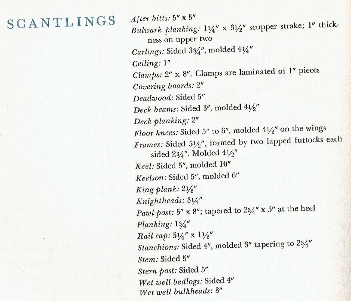
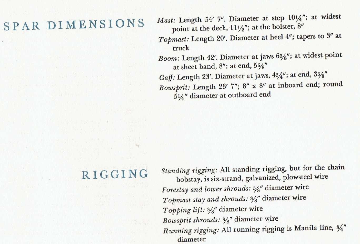
Dave, You sorta have to use both. a digital caliper of sufficient quality will have 3 readouts: metric, Imperial digital, Imperial fractions. I would advise ignoring the fractions option. For length a tick strip can save on interpolation errors. As has been presented above, the wise choice is to use the units of the original plans and tables of scantlings. Interpolation and conversion errors are far too easy to make. @Bob Cleek @allanyed National differences are obvious to any beginner looking at ANM - with the different scales on every plan - and add to that: the exact standardization within a country being a bit fuzzy - I had not put this together until now, but obsessing about +/- 0.01" on model timber stock is a wasteful and unproductive thing to worry about. A foot or two translated to scale difference in a model hull is nothing to worry about. The actual vessel would have a significant +/-. The key factor is to be internally consistence.
-
It is not an ideal shape for me, but I tried another armchair experiment. I checked McMaster-Carr and they have Aluminum "U" bar stock with dimensions that are close. A 2 foot bar is <$50. a box of 1/8"-1/4" ( or what works) long enough thumb screws A pilot drill bit and a tap How many can be had depends on how wide are the slices but if the whole bar is done, I am betting that the cost per unit would be less than ready made.
-
Steve, I am not clear in following which machine that you are using for which task. I will list my process instead of dissecting yours. I generally start with 8x4 rough lumber if I have that option. I use the bandsaw to slice off planks that are close to one of the final dimension that I am after. The bandsaw product has a rougher surface than I want, but significantly better than what a saw mill blade does to the wood surface. I try to make the thickness just enough that 80 grit on a thickness sander will remove all of the bandsaw blade scars but leave enough so the a 150 grit and then final 220 grit will to get to spec without having to do an excessive number of passes. The edges of these stock planks are saw mill rough. The 90 degree cut to get to a final construction size piece, I do using my Byrnes table saw. The product from it is smooth enough not to need sanding before joinery. A bandsaw being used for slicing off deck planks, deck beams, hull planking,, etc. will want additional sanding and small strips of wood are difficult to thickness sand. For the first pass on the table saw, there is always the hope that the edge is just smooth enough to ride against the fence for a clean straight cut - and scrap this first one, or first use an edger ( which I do not have) - or a jig that I bought a while ago - a sort of very long Al "C" clamp that rides against the fence and holds the board for a straight first cut. In my hands, I can see no way that using a bandsaw to do the final cut for wood strips would not totally frustrate me. For my frame timbers, - my bandsaw and then thickness sander produces planks that are frame thickness, The rough edges do not matter because I scroll cut the timbers from the body of the plank and the edges are not in it. The occasional stealth check can be frustrating, but the extra 1/2" of wood usually available from not surface or edge planed lumber is something that I prefer.
-
@Egilman @Dr PR Thank you for the direction. I think it was DesignCAD 3D - the V. 1.0 or so that clued me to the realization that, although I may be able to generate a hull, I could not use it to take a cross section at any Z (point along the keel) and get a frame outline. I was desperate to find a way to avoid hand plotting 200 plus frame outline shapes. I have come to understand that a 3D modeler can do this. But, by then I has found an entirely different and much more efficient and much faster way to reach my goal. What my bucket list objective is to replicate one the Anthony Deane's 1673 first rate liners using the directions in his Doctrine. I got a ways into it long ago when the first modern edition was published. This was on Mylar. A key that I missed at the time was how many cross sections were drawn. I thought that it was done for every station. What I could not determine was which parameters were adjusted for each interval. It turns out that I totally misunderstood the process. There were only 3 cross sections during the design stage. The bow and aft sections could even be "slud" to get a sharp or blunt entry and a lean or abrupt run aft. Battens were used to get the run. Diagonals and ultimately a model (with a framing style that simulated diagonals) were used to "prove" the hull shape. No flats and no hollows. There is no 3D needed. It sounds like DesignCAD 2D is a way. That is if it allows for the really huge circles whose arcs define the wales, decks and other construction curves needed. I recommend following Deane's exercises as way to gain some understanding of the old hull design techniques and why all those strange lines that are not a part of actual wood shapes are on those old plans from the 18th century. Essentially all of the 17th century ones did not survive time. At my present age, this project is mostly a fantasy, but it is a comfort to see that it is a possibility using electrons instead of graphite.
-
Steve, Tracking on a bandsaw is not about the blade staying where you set it on the guide wheels. I would expect that most any model saw will hold where it is placed. The critical factor is the sort of cut it makes in wood. Resawing is the high stress test for a saw. As long as your cuts are producing slices that are parallel and all in the same plane - using your present position - well, if it ain't broke, don't change it. If it starts doing an "S" along the cut, or the thickness at the start is different from the thickness at the end (even though still perfectly vertical) try moving the blade at the top wheel such that the teeth are at the center. I would say the same if it started giving a wedge ( an angle when viewed end on ), but I suspect that what this sort of wedge is telling you is that the blade is no longer sharp enough and needs to be replaced. You could try adjusting the blade position, but all that might do is prolong the bad cuts. The cost for doing that test is wasted wood. If I am correct about the blade being too dull, soon starts the banging, and then the snap. As an aside, no matter the cut, any new bang, bang, bang, means that there is a crack in the blade, Stop and replace, it will not take long for the blade the snap anyway. Most who have a tabletop bandsaw probably never use it for resawing. They use it for scroll cuts and maybe short crosscuts - it is quick and dirty at crosscutting. With a scroll cut, a continuous adjustment is being made as the work moves against the saw. The center of the blade at the crown of the top wheel is probably sufficient for this and is easy to do. What you are doing is pushing the saw to its extreme limits in doing thick hardwood resawing. With a big saw and a carbide tip blade or bimetal blade, the work is repetitive, mostly, and on cruise, mostly, although it still deserves close and constant attention. With the small machine, each slice is likely to be a whole new adventure.