


3DShipWright
-
Posts
249 -
Joined
-
Last visited
Content Type
Profiles
Forums
Gallery
Events
Everything posted by 3DShipWright
-
Nate's PANDORA in 3D
3DShipWright replied to 3DShipWright's topic in CAD and 3D Modelling/Drafting Plans with Software
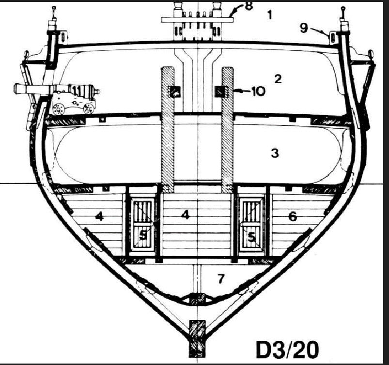
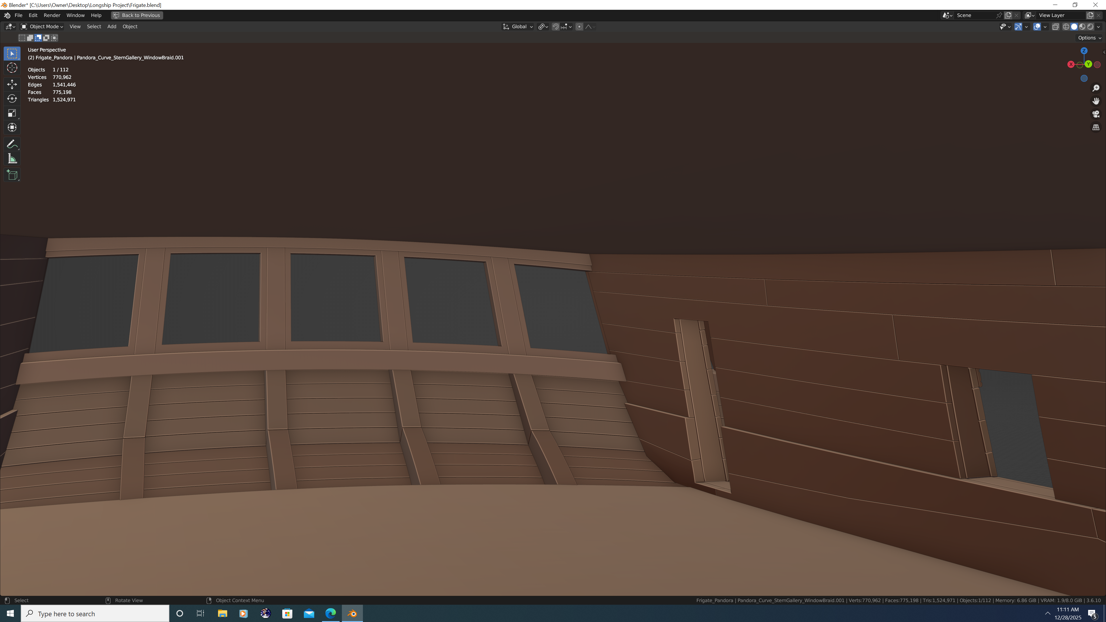
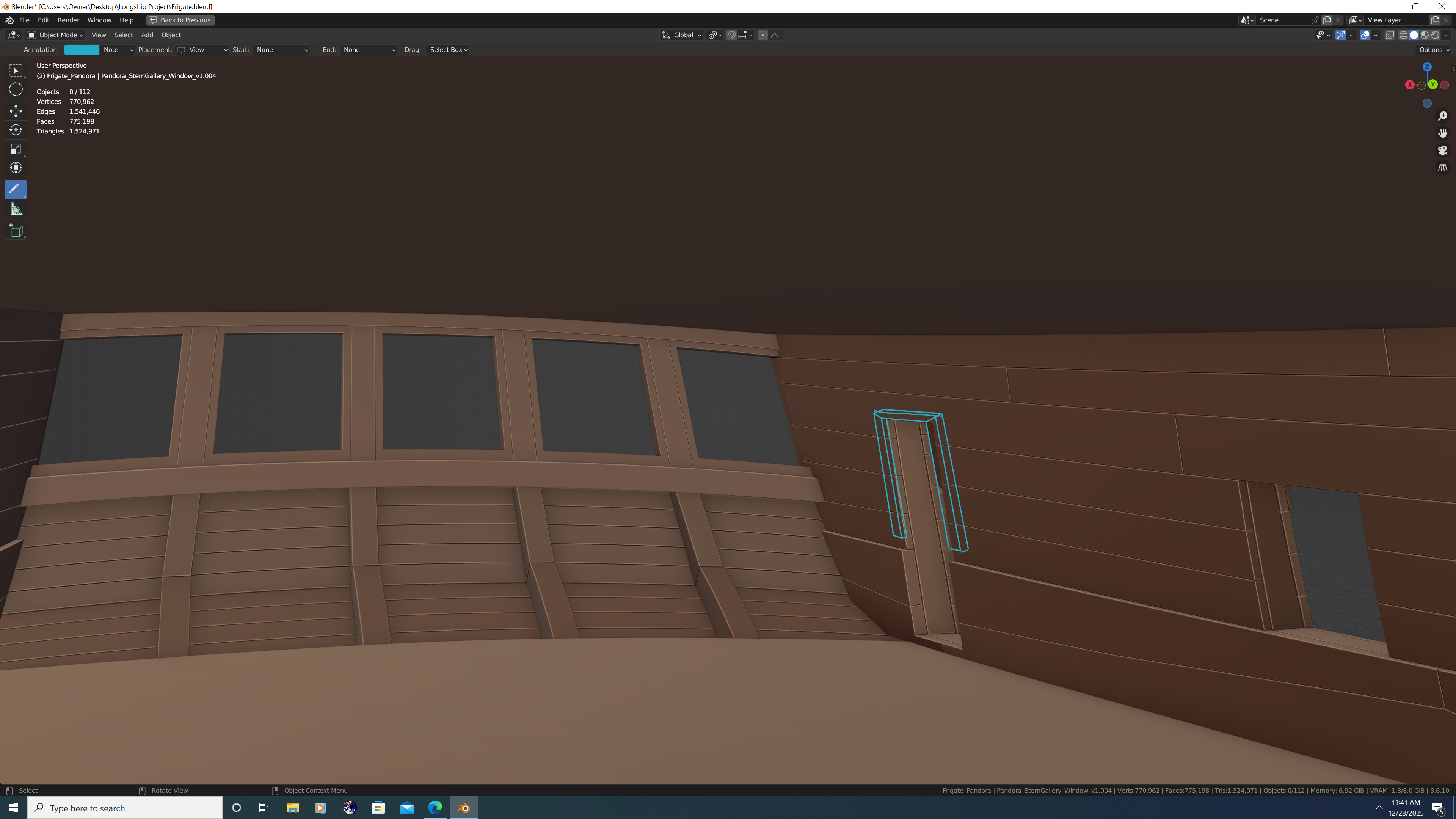
Hey Folks, I could use some help regarding the inside of the great cabin. I'd be much obliged to anyone who can answer any of the below questions. First, an image of the inside as it currently stands... And for clarification, I have not yet modelled the Bench, Bench Step, or Rudder Head Cover as I will have additional questions about those once I get the interior situated. On to my questions: Are the deckhouse doors really only about 4 1/2 feet tall? I think it's perfectly plausible given Pandora was a small frigate and people were shorter back then, but I thought it worth seeking confirmation from you fine folks. Because the interior planking is thinker near the deck clamps, ceilings and waterways (latter not yet modelled) how is a door actually mounted there? The hinges would need to be mounted on an even perch to allow the door to swing open properly, correct? If so, is this accomplished with a large door frame to even things out? Or perhaps the paneling in the great cabin brings the two sections flush? Or perhaps it's a bit of both? (no illustration provided as you get the idea) Speaking of paneling - is my basic assumption that it sits on top of the inner planking correct? Put another way, the internal paneling is in addition to and not in lieu of the internal planking in the aft cabin. Yes? Thank you all in advance, -N.


-
Nate's PANDORA in 3D
3DShipWright replied to 3DShipWright's topic in CAD and 3D Modelling/Drafting Plans with Software
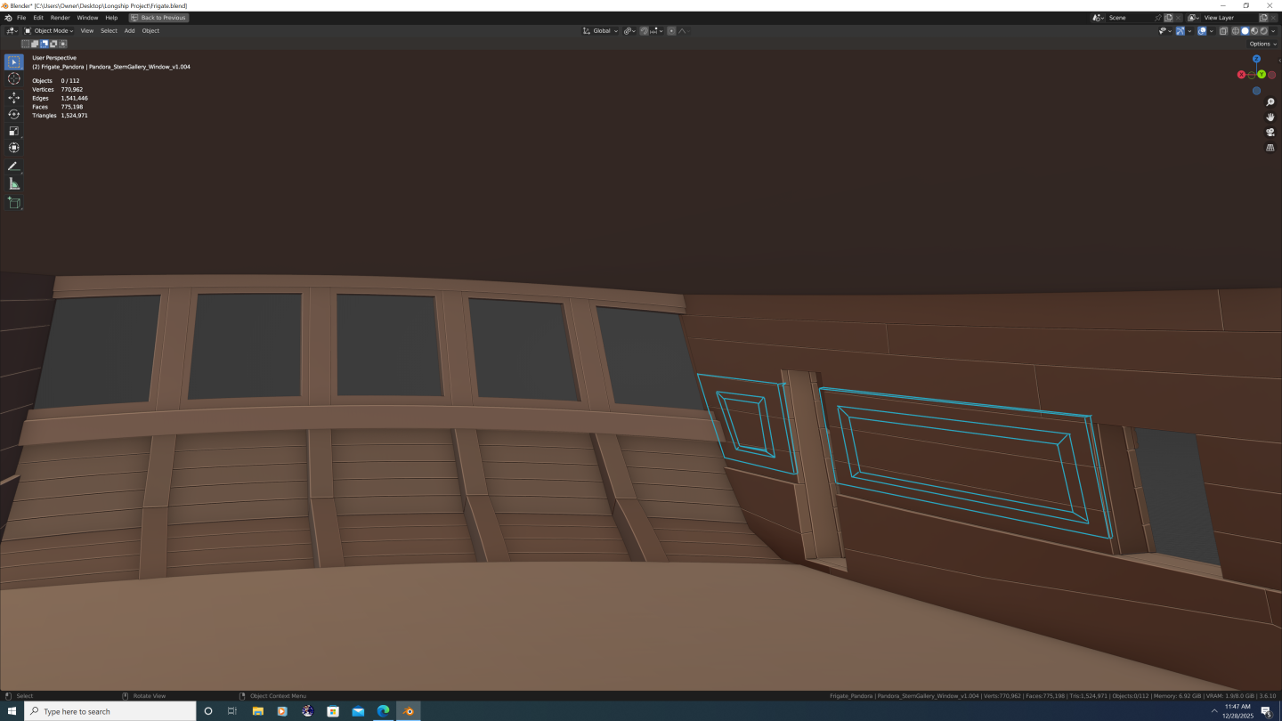
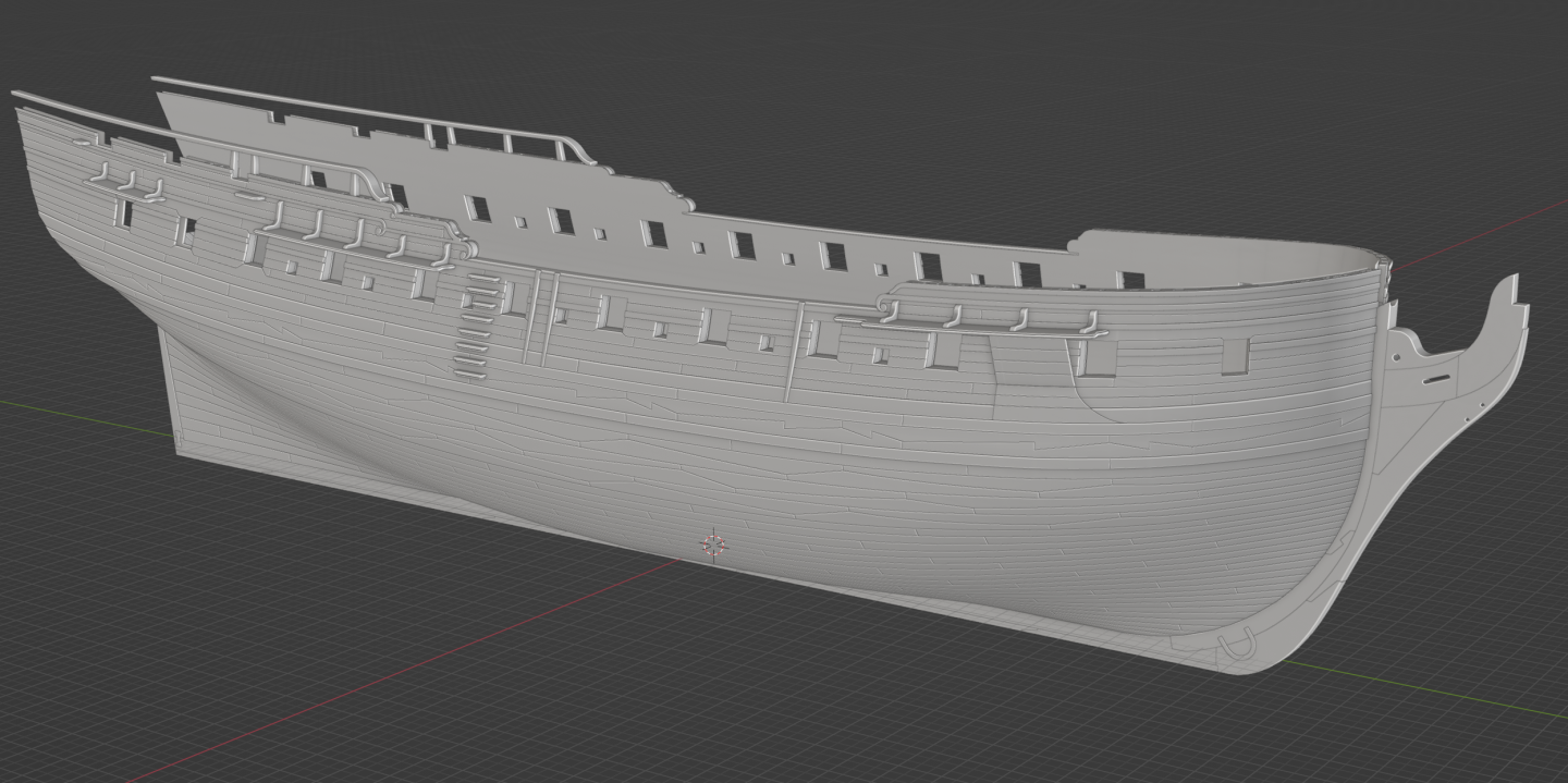
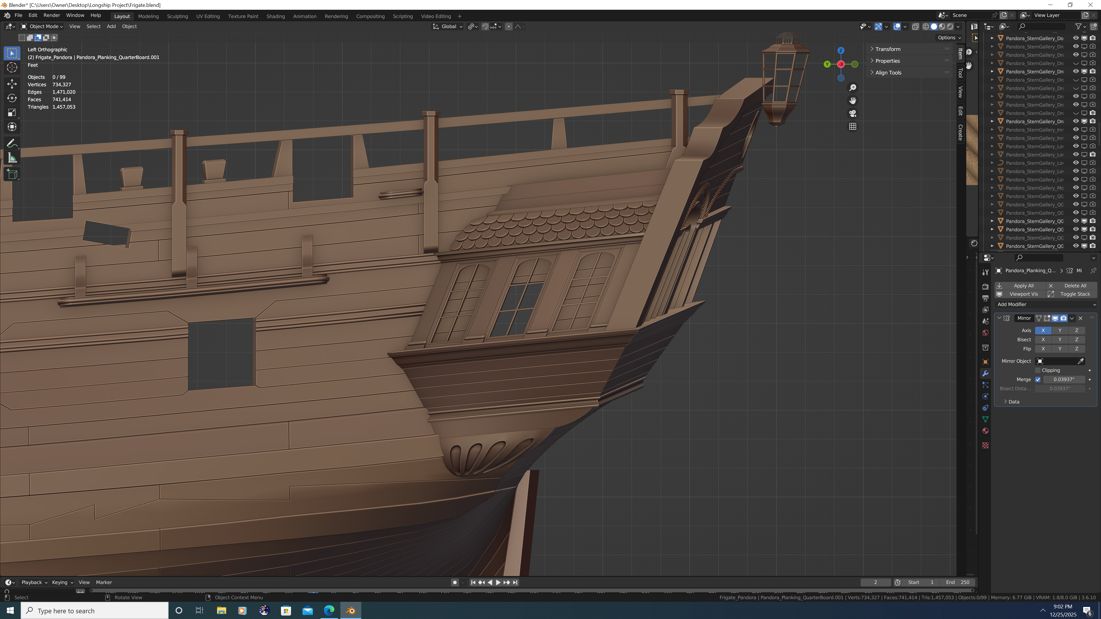
Working on the galleries. I remember one particular ship in the RMG archive of the Porcupine class was illustrated with arched windows on the quarter gallery and I really liked the style. Still working on the drops - getting the shapes correct has been a bit of a crap shoot 🤣🤣 Bad puns aside, I'm getting excited now that some of the more fine details are starting to come out. The internal planking has been completed through the lower deck. The decks themselves are merely placeholders at this point. That's it for now. Happy Holidays All!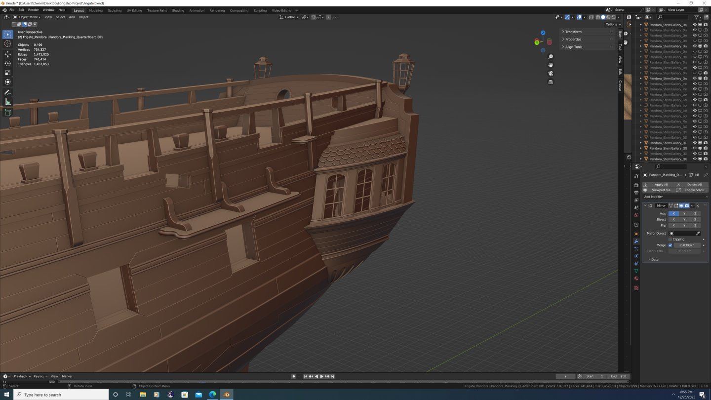


-
Nate's PANDORA in 3D
3DShipWright replied to 3DShipWright's topic in CAD and 3D Modelling/Drafting Plans with Software
@Pirate adam Thanks Adam, I too agree that the transoms in the AoTS book are somewhat incorrect, albeit for a different reason than the one you provided, which I shall address first: First, let me state that you are correct - a 24-gun ship has four transoms. Sixth-rates and below have no transoms below the Deck Transom, meaning the Deck Transom rests directly upon the fashion piece and any filling cant frames. Above the Deck Transom there are one or more Filling Transoms (I'll come back to this in a moment) and finally, the Wing Transom. However, depending upon the class of ship and the Deck Transom's relative position to the Gun Deck - which refers to the lower deck in Pandora's and Crocodile's case despite there being no guns - the Deck Transom may need to be split. (The image below is of the HMS Eurydice of 1781. HMS Eurydice was cited in the AoTS book as the source material for Pandora's framing profile.) BTW - In case you're wondering why the admiralty plans depict the wing and filling transoms pointing at different angles, it's because the draftsman is trying to depict the sweep of the transoms outward as they curve to follow the crossfall of the deck (shown with how the Wing Transom was drawn), as well as what the centerline of the transoms look like (shown with how the Filling Transoms were drawn), or both (shown with how the Deck Transom was drawn, which is why it is drawn as a wedge shape). In summary, there are four transoms, but because the gun/lower deck bisects the deck transom, there are technically five transom pieces. Bear in mind this is merely my interpretation, but it seems to fit with all available data. Lastly, as said, I did have a few problems with how they did the transoms for Pandora. I'll be back in another post soon to share that part and get your thoughts. Best, -N.
-
Nate's PANDORA in 3D
3DShipWright replied to 3DShipWright's topic in CAD and 3D Modelling/Drafting Plans with Software
Thanks for the insights Trevor. And please know that feedback is always appreciated, and that I truly believe that constructive criticism is just that... constructive. Best Regards, -Nate -
Nate's PANDORA in 3D
3DShipWright replied to 3DShipWright's topic in CAD and 3D Modelling/Drafting Plans with Software
I'm not seeing it. There should be a definite stair stepping effect. Again, there are also no frame pairs depicted, no sweep or sheave port sills or cut-outs, there should be no stepping scarf for the fore cant frames that extends to the outer planking, and several of the aft bollards are depicted as wider than the timbers from which they were carved. Nothing I'm saying should be controversial here: These disposition plans simply cannot possibly be accurate and/or complete. Agreed 100% But you're actually making my point for me: what was the intent of an admiralty disposition plan? Nowhere is it written that those disposition plans were hard and fast blueprints for a ship's framing. The actual framing relies on all those established scantling tables, as well as the available seasoned(or partially seasoned in Pandora's case) timber. And remember, Ron Coleman co-authored the AoTS Pandora book, and he was the curator of the actual Pandora exhibit in Queensland, meaning much of what shaped the designs in the book were pieces of actual wreckage. At the end of the day, I guess it doesn't matter if folks think my framing is historically accurate, it just seems odd to me the way people will cling to the infallibility of NMM/RMG plans with religious conviction, even when they don't hold up to evidence/scrutiny/logic. Best, -Nate -
Nate's PANDORA in 3D
3DShipWright replied to 3DShipWright's topic in CAD and 3D Modelling/Drafting Plans with Software
If I may ask, what discrepancies are you referring to? -
Nate's PANDORA in 3D
3DShipWright replied to 3DShipWright's topic in CAD and 3D Modelling/Drafting Plans with Software
@druxey and @Pirate adam Thank you both for your feedback. I probably should've clarified that it was just the one frame that I wasn't sure about. I'm actually quite confident that the real ship's frames bore a much closer resemblance to how they are depicted the AoTS book than they do any disposition plans on the NMM/RMG site. So one VERY important thing to note when it comes to frames. is that frame disposition plan IS NOT to be interpreted as a comprehensive framing plan. You cannot treat everything from RMG as gospel any more than you can treat diagrams in the AoTS as gospel. This is not to say that these plans are 'wrong' rather, to my eyes they are merely a simplification of the actual frame plan (at least the ones signed by Williams are) In fact, referencing the HMS Sphinx diagram below, there are several obvious examples as to why this plan cannot be the actual frame layout for the ship: The siding of each futtock above the floor timbers do not dither/diminish as they are supposed to in real life. The fact that futtocks get thinner as you go up is well established and their precise proportions documented in various scantling tables (I used shipbuilders repository of 1788 pg. 95-96 if you wish to double check my work. Scantlings of a 24-gun ship at midship (percentages rounded) First futtock of floor timbers 98% Second futtock of first futtock 87% Third futtock of second futtock 95% Fourth futtock of third futtock 97% Top timbers of fourth futtock 99% Crunching these numbers, the top timbers should be approx 77% the width of the floor timbers. This detail is clearly omitted on the Sphinx plan. @druxey this is why the top timbers appear more spread out on my model. There are no cut-outs, nor sills, depicted for either the sweep ports or the sheave ports. This is further proof the RMG frame plans for these smaller ships are not comprehensive The perpendiculars are evenly spaced, which once again is contrary to the established 2-1-1 floor timber arrangement These are just the most obvious reasons the RMH/NMM plans can't be 'as done in real life'. Now, that still begs the question: Where on earth did Pandora's Framework come from? Well, I think Tim McKay did the same thing I have done, that is, derive a frame plan that actually conforms to all documented metrics and scantling data. Lots and lots of math and calculations. I've spent the better part of a year essentially re-designing Pandora from the ground up and I've reached a frame plan that is very close to, but not identical to, what is in the book. Just my two cents. Best, -Nate
-
Nate's PANDORA in 3D
3DShipWright replied to 3DShipWright's topic in CAD and 3D Modelling/Drafting Plans with Software
Good to hear from you Druxey! I hope you're doing well. That particular futtock frame is odd indeed, and the result undoubtably creates a structural weakness beneath gunport #3. Question - when you say 'looks odd' are you simply making an observation, or do you suspect it may be historically incorrect? I ask because I have it modelled the same way it was drawn in the AoTS book (Frame #31, figure B5/1, page 33) But like I said, it seems odd to me as well, so if you've any evidence to refute this drawing, I'd love to have a look at it. Best regards, -N
-
Nate's PANDORA in 3D
3DShipWright replied to 3DShipWright's topic in CAD and 3D Modelling/Drafting Plans with Software
@Loracs - I'm certainly not opposed to the idea of making a formal tutorial series on ship building in Blender. I've received a handful of requests to do so, be it written or video format. However, I hesitate for a few reasons: My passion is making high-quality digital boats and ships. The key word here is digital. My work has yielded some amazing renders and animations, but they don't translate to physical assets (CNC parts/3D printing) nor even video games due to their high poly count. A majority of folks loose interest right there. Secondly, you're correct, making a tutorial in any format is time consuming. I'd be happy to do it, the problem is each person would want something different, and that's assuming they know blender well enough to follow along. For example, this is a gross simplification of my actual process, step by step: Import the sheer and body half-breadth and plans for the ship you want to build Scale and align them to the global origin of the ship - top-of-rabbet, station (+) - then rotate them to be visible from the orthographic X, Y, or Z axis Add a curve for each station line and use the curve tools to trace each line atop the molded-breadth plan Then position each curve font to back at its appropriate location using the sheer plan Mirror all curves either before or after midship so that all curves are on the same side of the ship. Convert all curves to meshes and then join them into a single object that contains all station lines Ensure each station line has the same number of vertices, and furthermore that the vertices on each station line are equal to one more than the number of strakes on the exterior hull (verts=n+1) Then ensure that the vertices are evenly distributed along the line (the Space function of the Loop Tools add-on in Blender can assist with this) Loft all station lines together (Loft function of Loop Tools add-on). You now have a flat sheet that represents one side of your hull. The result will likely look blocky, so either: Loop cut interpreted station lines between the actual stations, or... Subdivide the mesh using the Sub-serf modifier. Neither method is perfect. The Sub-serf modifier will automatically sooth everything out for you, but it will do so by distorting (shrinking) the original station lines as well as doubling the number of strakes. I prefer to manually loop cut between each station, then smooth out the new interpolated lines using the 'Curve' function of the Loop Tools add-on, but for some weir reason, you actually only select the original stations when doing this, but the function will operate upon the non-selected lines. No idea why it works this way, but it does. Anyway, you get the idea... Thing is if you follow everything I wrote above, it only gets you to this: Summing up - that's my hesitation in doing tutorials. However, I have been working with @CDR_Ret for a couple years now and I think he's got a pretty good grasp on the general flow I'm discussing here. And unlike myself, he has professional experience in technical writing and educational texts. He and I have kicked around the idea of transcribing some of this 'knowledge' if you can call it that, for other aspiring Blender artists. @CDR_Ret - Not to put you on the spot Terry, but what do you think? Knowing what you now know about this process, is the fundamentals of 3D shiprighting in Blender something you think we could throw together for folks? Like I sad in my opening, happy to consider it, just wanna make sure the juice is worth the squeeze. Best wishes to you both, and Happy Thanksgiving to my American compatriots! Nate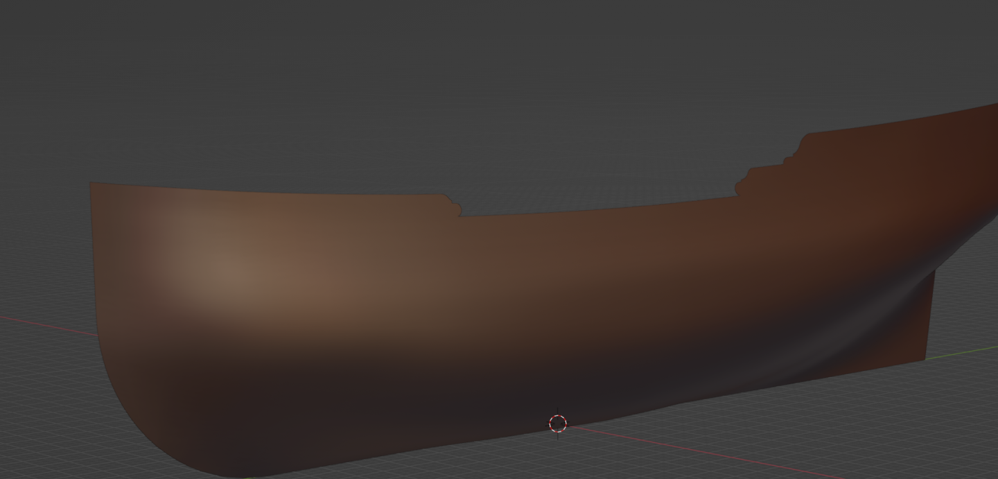
-
Nate's PANDORA in 3D
3DShipWright replied to 3DShipWright's topic in CAD and 3D Modelling/Drafting Plans with Software
Oh good, nice to know I don't have to worry about texturing her then 😆 -
Nate's PANDORA in 3D
3DShipWright replied to 3DShipWright's topic in CAD and 3D Modelling/Drafting Plans with Software
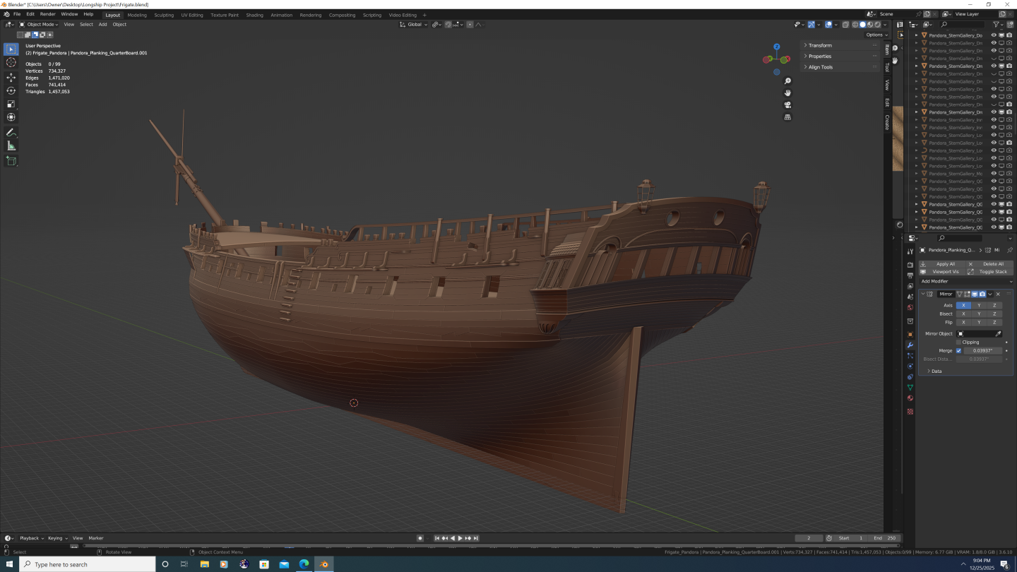
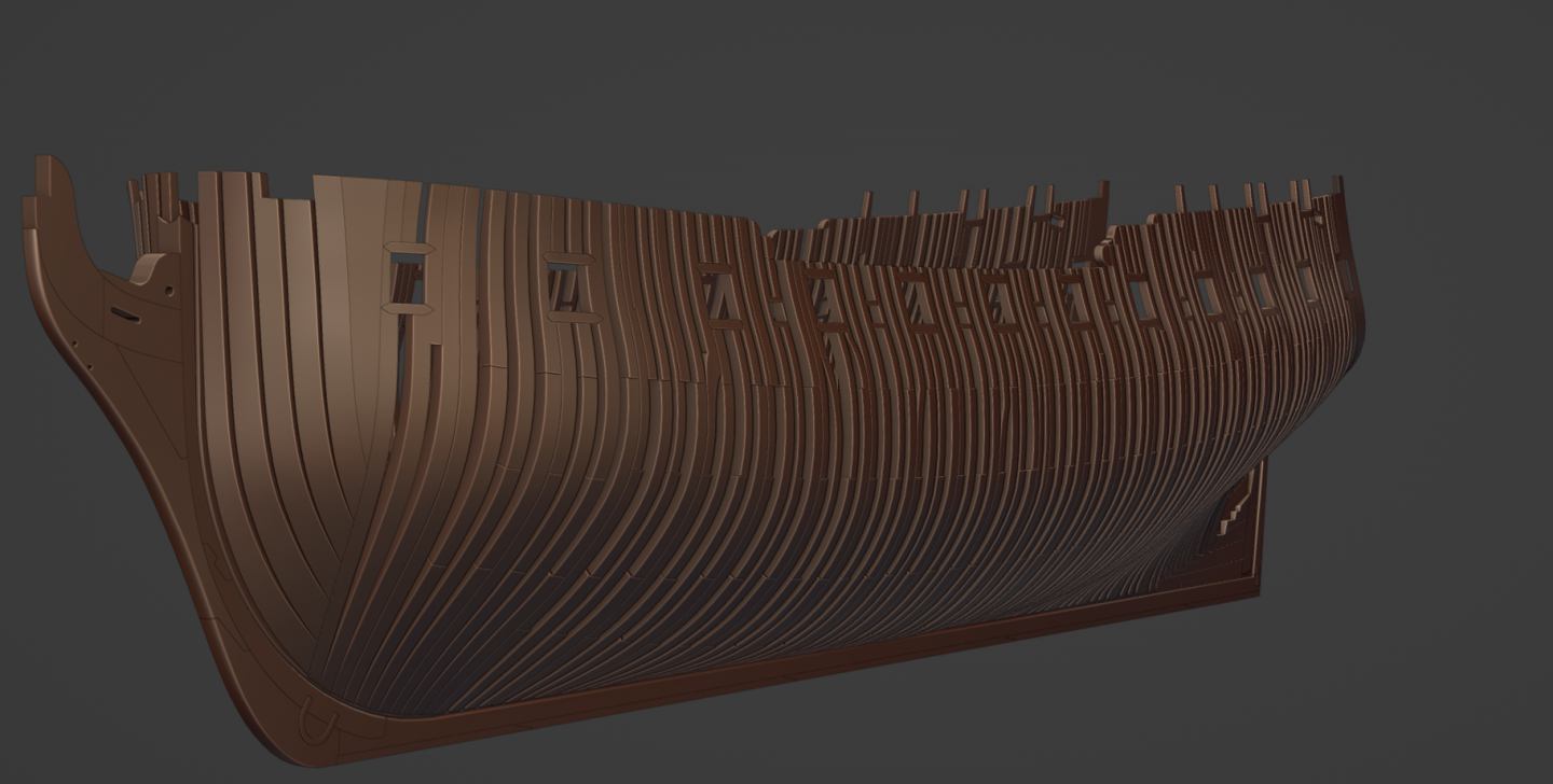
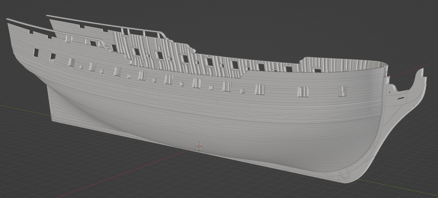
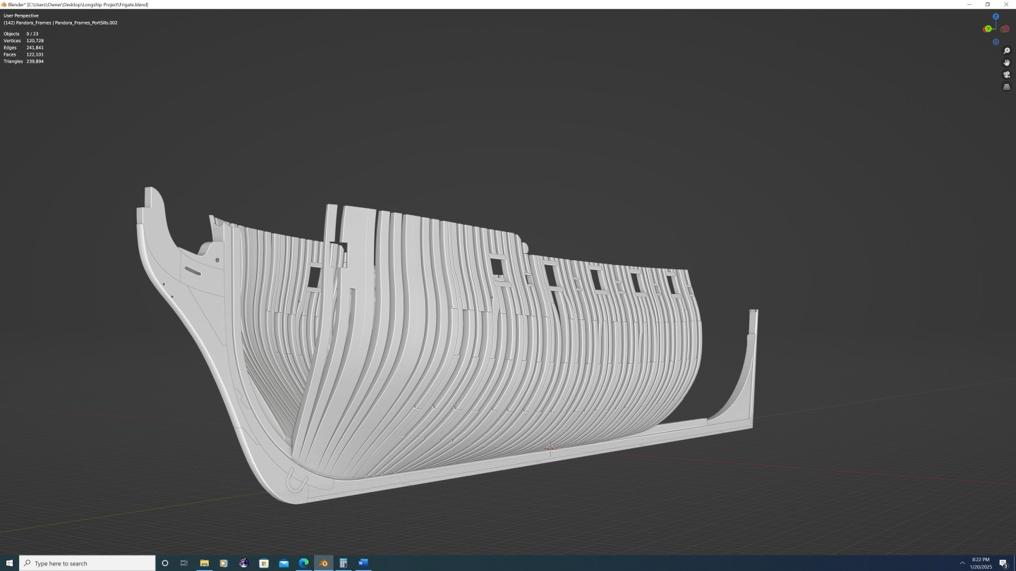
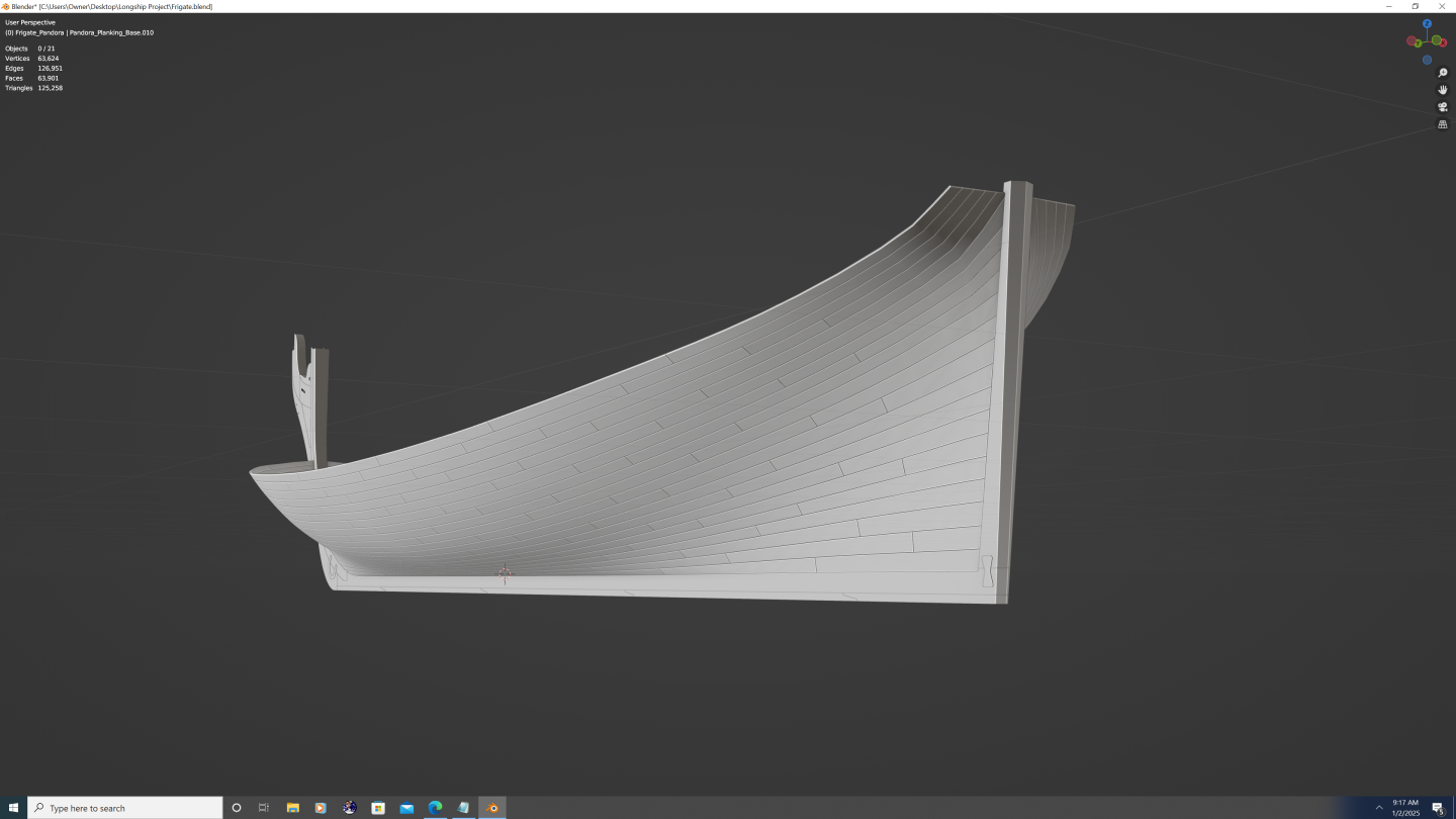
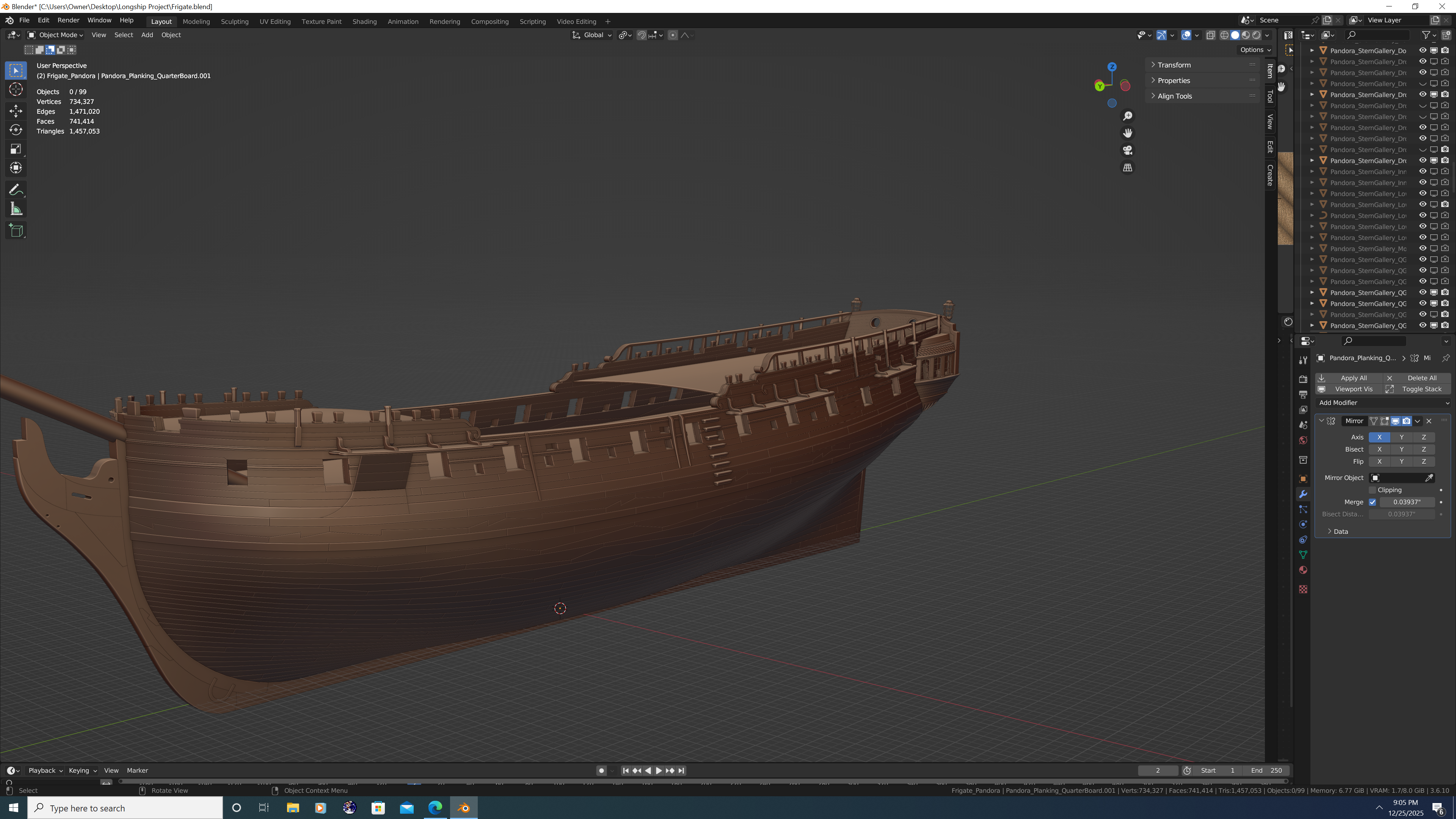
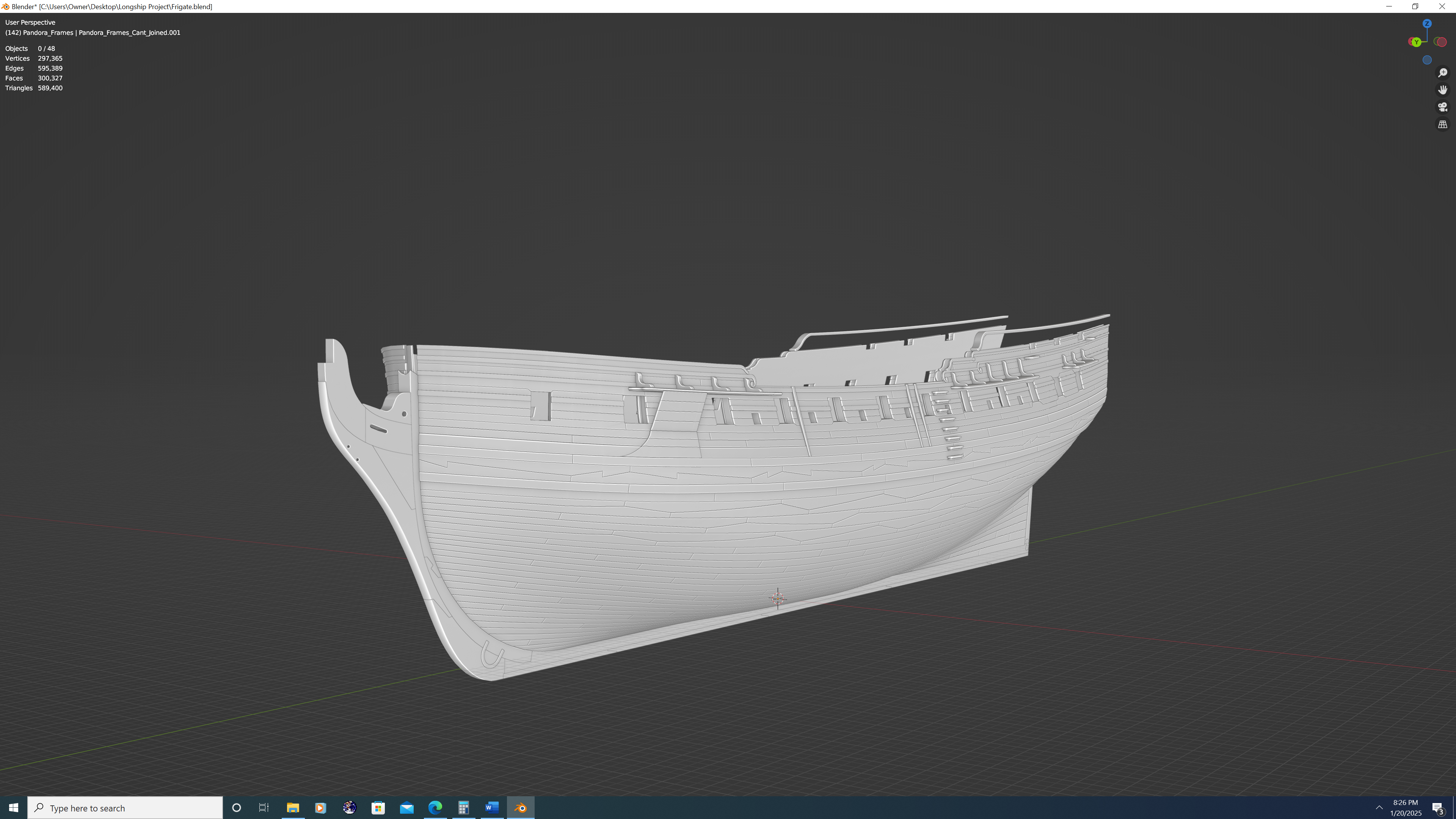
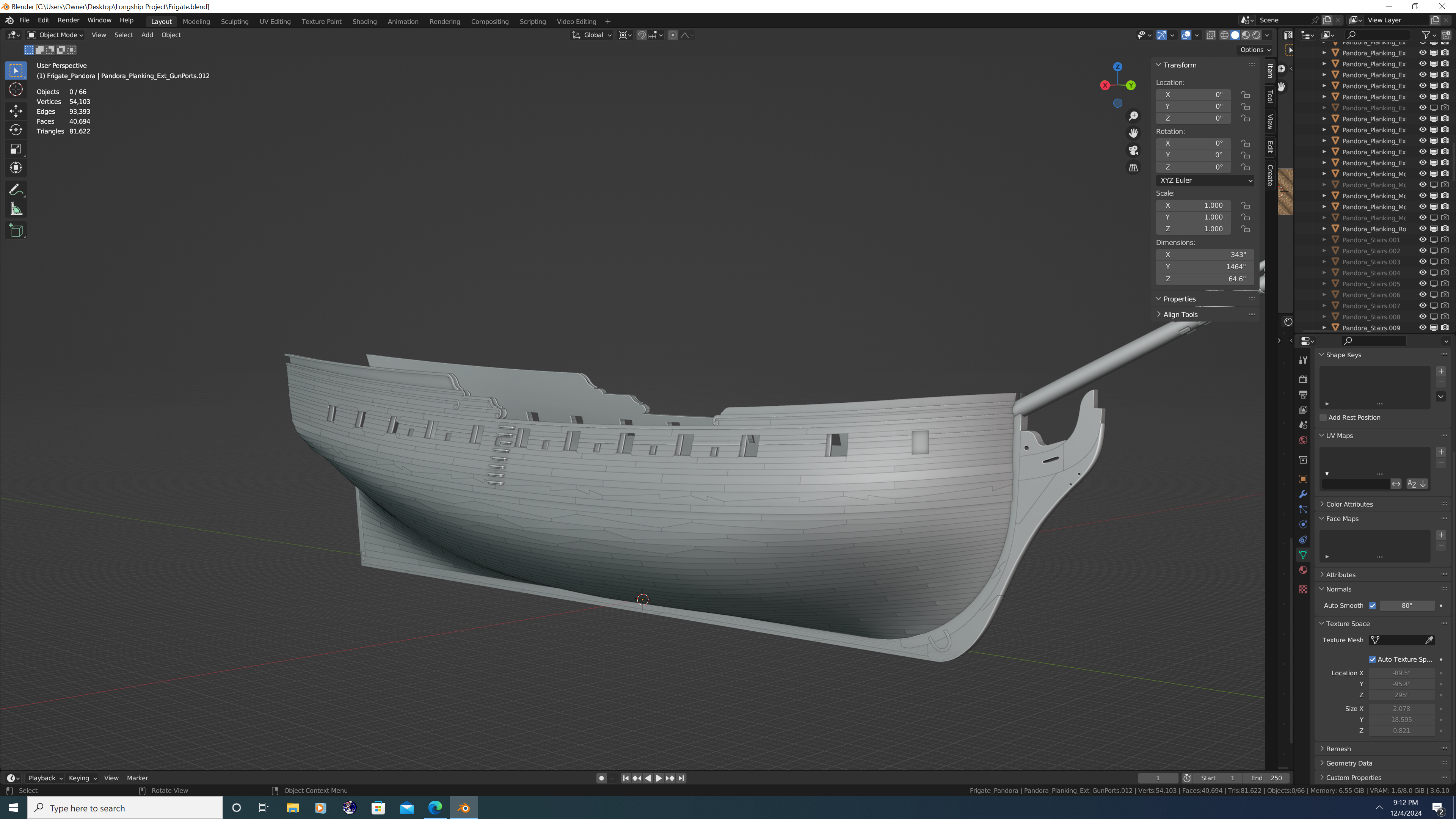
Dusting off my Pandora project for some work on it during the holidays. Here's a few current state images to kick things off...


-
Yet Another Pandora 3D build
3DShipWright replied to herask's topic in CAD and 3D Modelling/Drafting Plans with Software
But where's the nanite foliage, the voxel rendering of every single splinter of wood? Where's the cloth-on-cloth chaos simulations and the over 300 NPC's in each frame? 4/10 - Disappointing. 🤣🤣😋 -
Nate's PANDORA in 3D
3DShipWright replied to 3DShipWright's topic in CAD and 3D Modelling/Drafting Plans with Software
Ahh Pandora's framework: it's been so much fun /s. Kinda like when the progress bar shoots up to 90% and completely stalls

-
Nate's PANDORA in 3D
3DShipWright replied to 3DShipWright's topic in CAD and 3D Modelling/Drafting Plans with Software
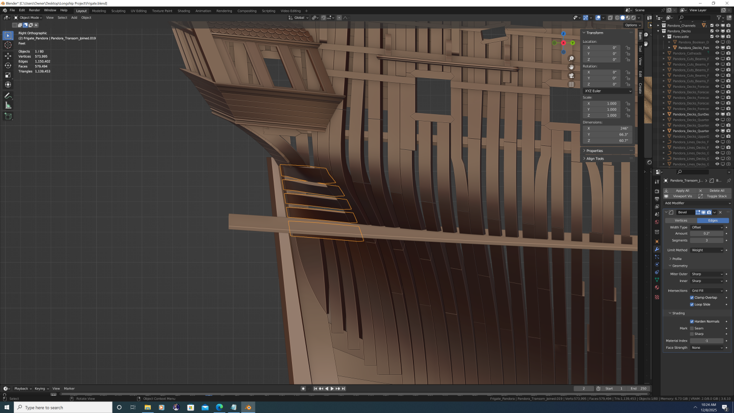
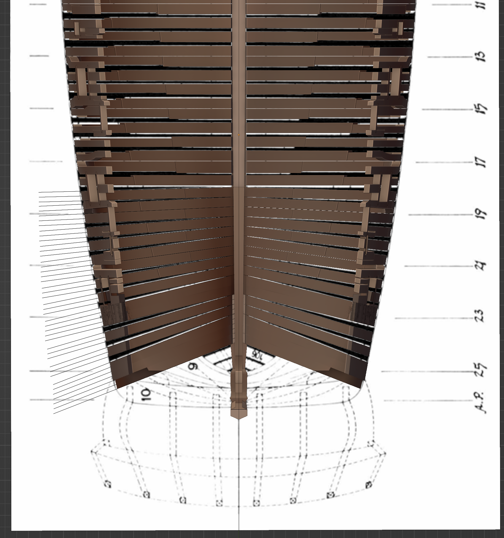
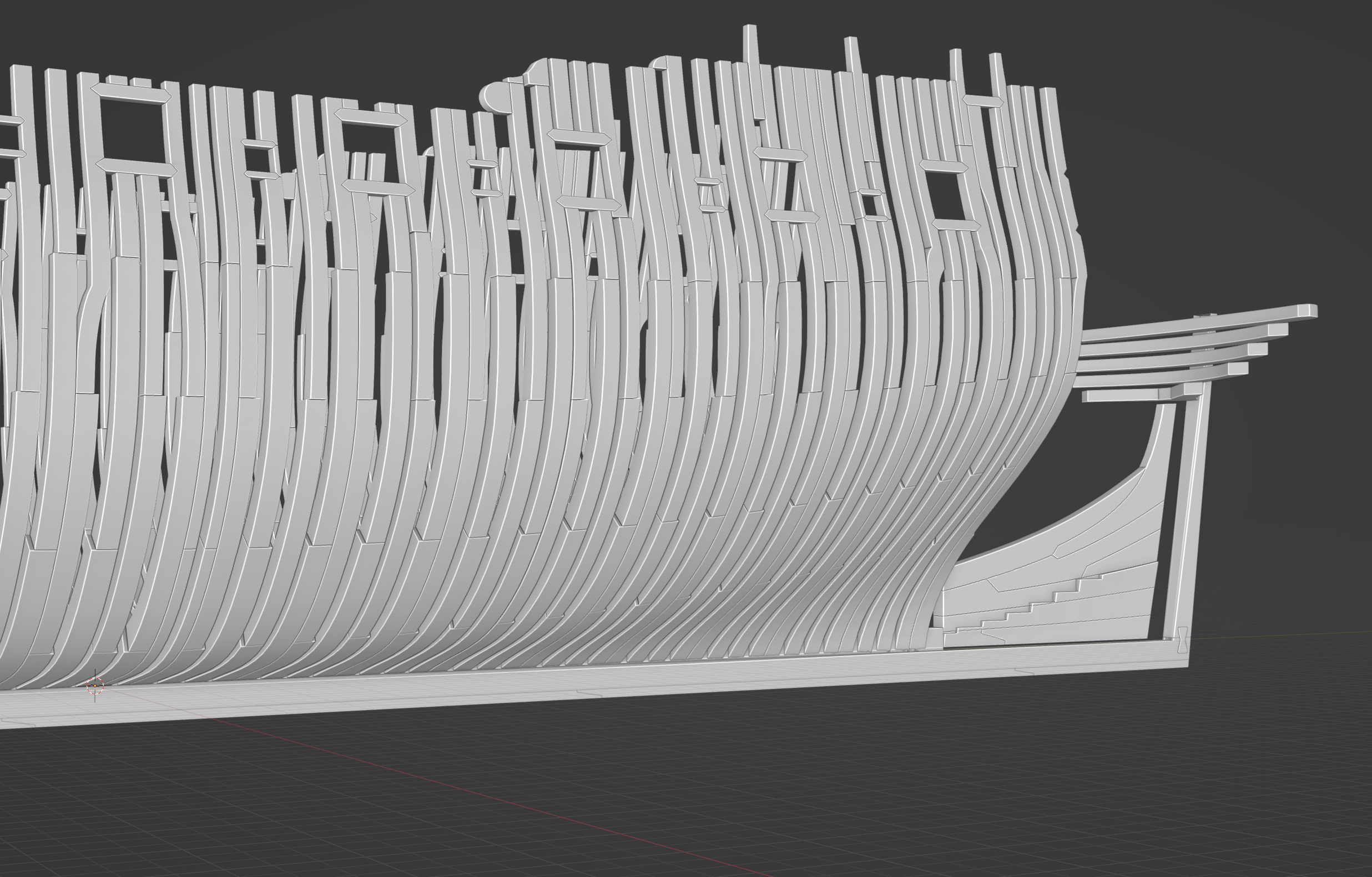
Framing update: prepping for the aft cant frames. Working on the deadwood pieces. Getting the stepping cuts to precisely follow the bearding line has been a challenge. Another challenge is that the siding (room and space) calls for aft cant frames at 10 inches, but that is a measure of the outboard siding. Inboard of the stepped scarf - where the frames abutt the deadwood - is actually smaller, which is why the second frame in each pair on each step appears narrower than the forward partner. The width of the aft frame is not even consistent, rather, it is a mathematical function of the angle. Translated into English... Yuck! Super slow-going, but I hope my attention to detail will be worth it in the end...

-
Yet Another Pandora 3D build
3DShipWright replied to herask's topic in CAD and 3D Modelling/Drafting Plans with Software
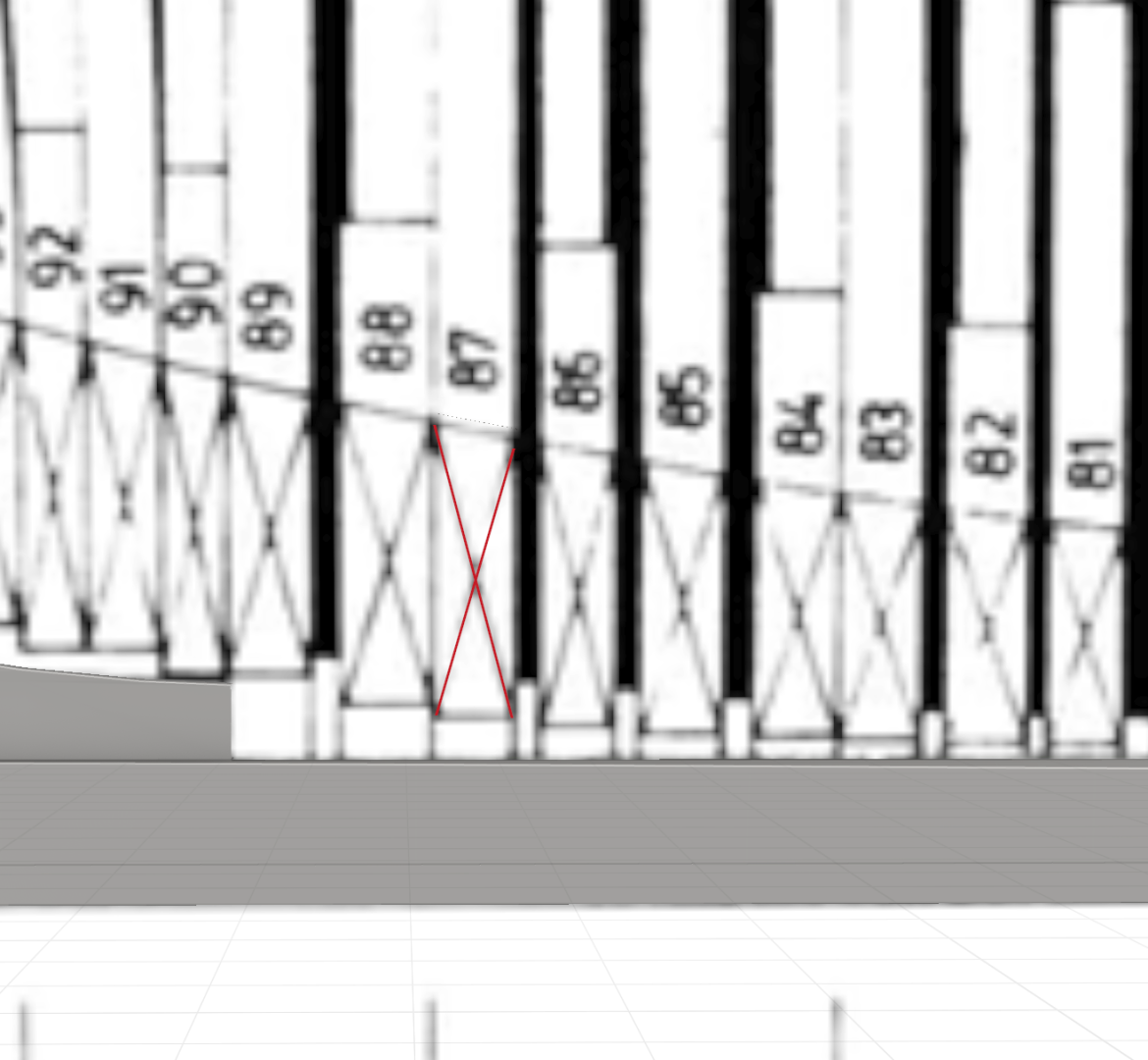
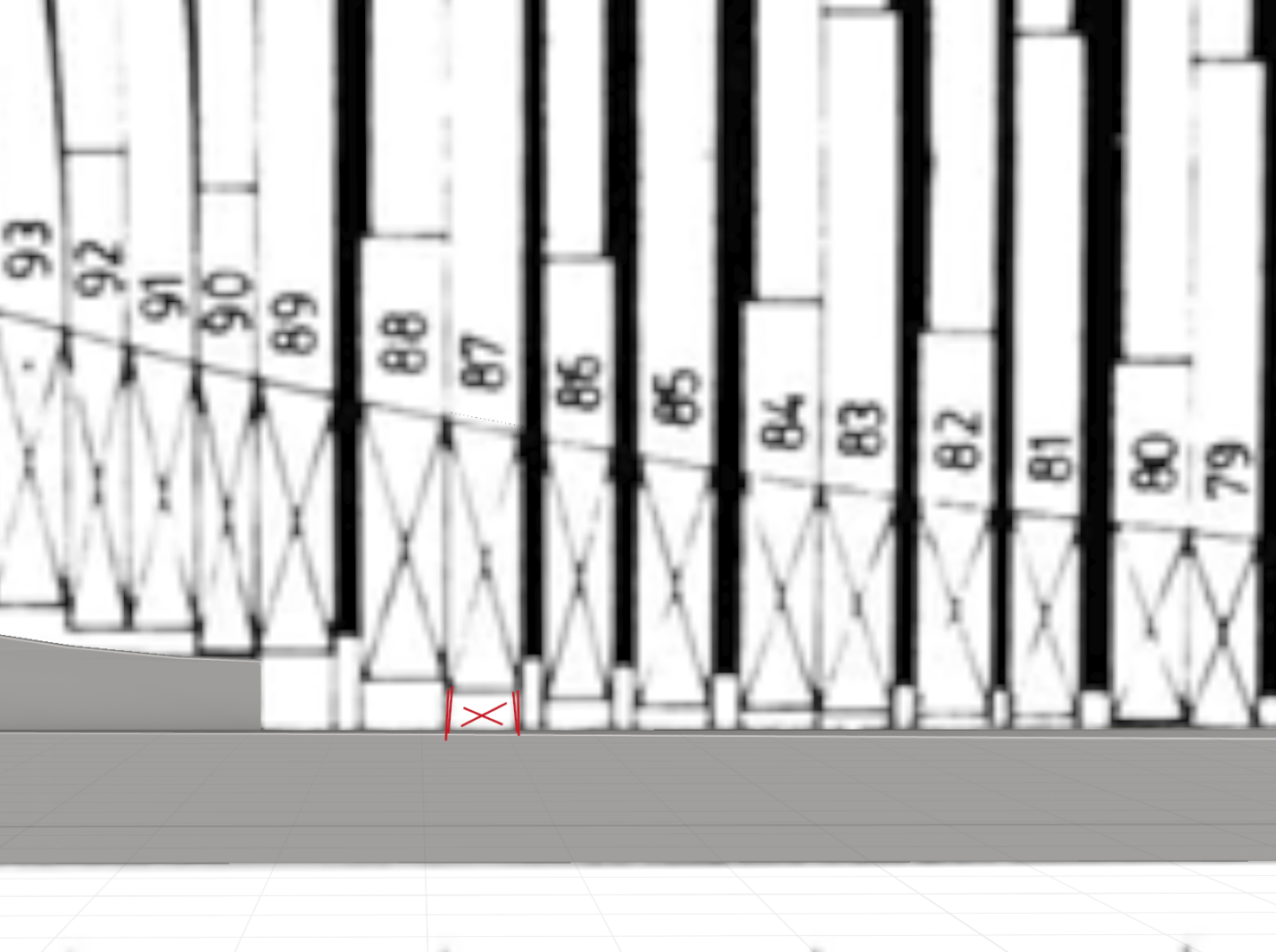
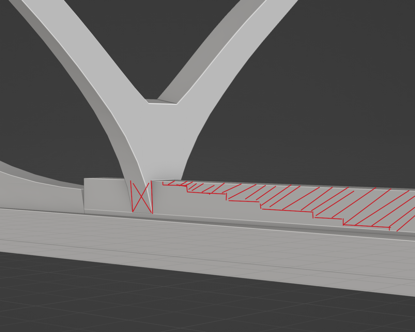
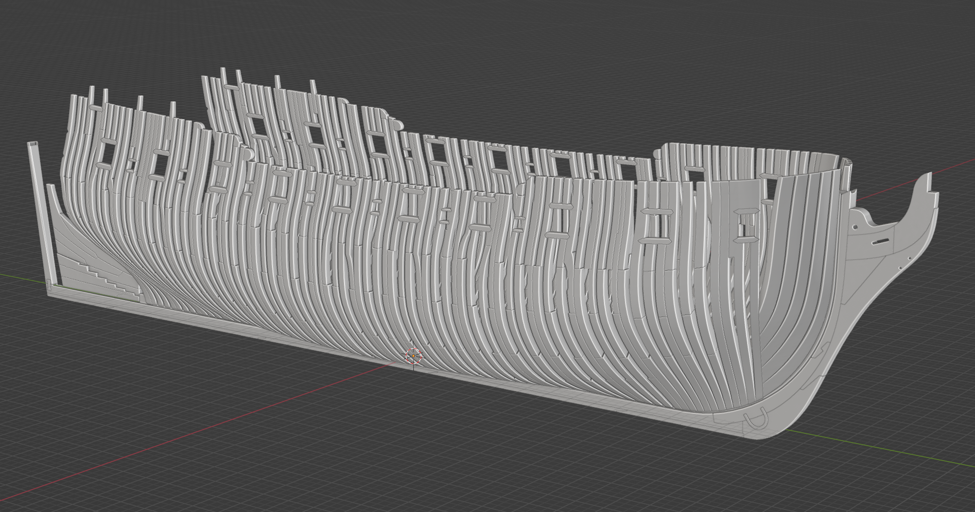
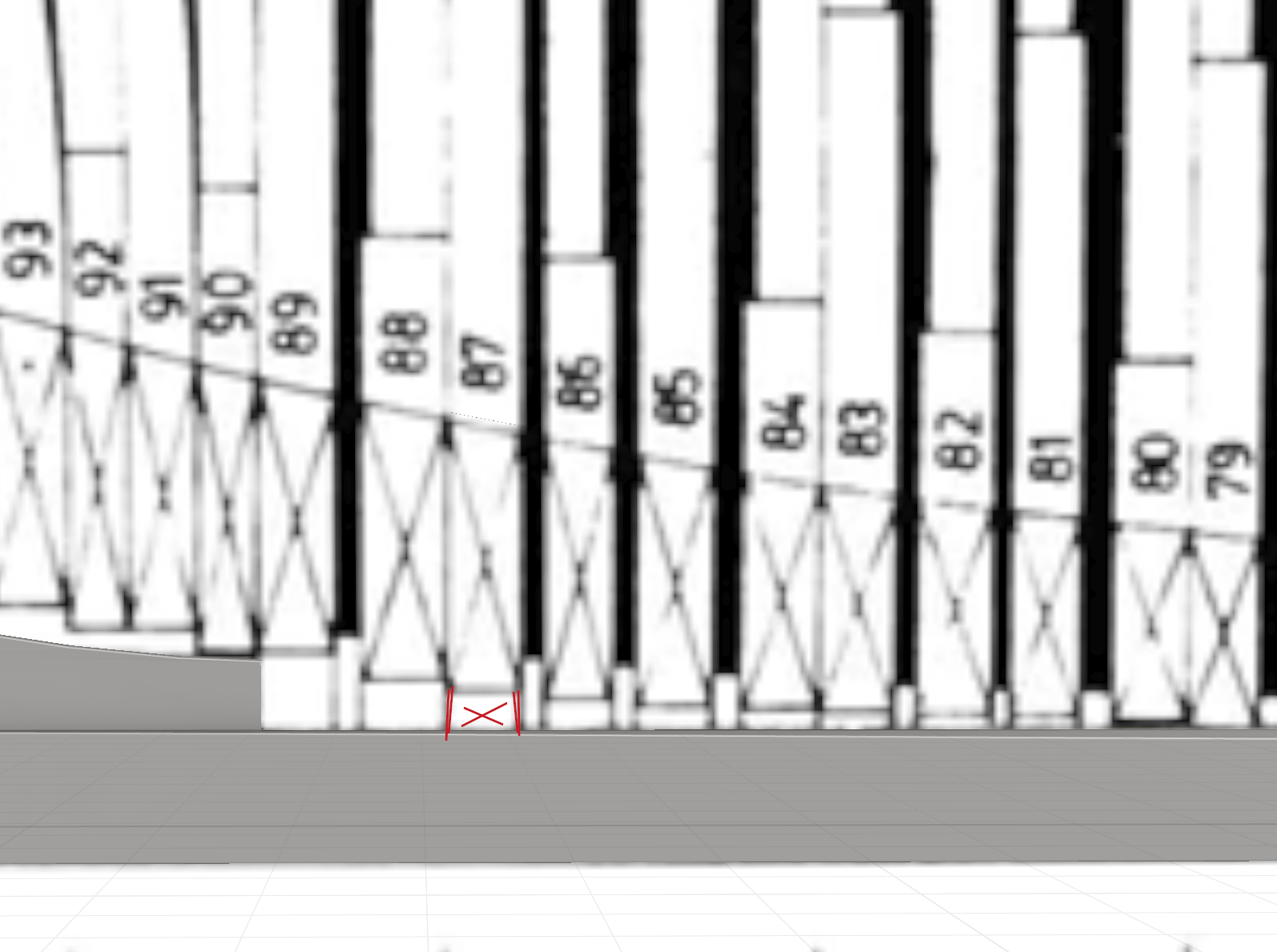
Dang you work fast... You're almost caught up to me and I've been at it for half a year now. Anyway, one comment on the frames: In all cases excepth the aft cant frames that rest atop the stepping scarf, the outside of the frames terminate at the top of the rabbet. the rising wood cuts higher and higher into the frames as you move aft, but the actual bottom of the frames remains at the top of the rabbet. This is why technically speaking, the bearding line on Pandora and others is only indistinguishable from the rabbet (top or back rabbet, I can't remember) on the aft deadwood and moving up the apron at the front. I know this may not be hard to understand without visuals, so to illustrate: The red X corresponds to the X on the plans, shown in the next image. It is where the two sides meet were you to bisect it down the middle of the keel Notice the vertical lines on the plans continue down. These represent how the external edges of the frames continue down to the rabbet. And shown again in 3D... (note - the red cutout lines are merely illustrative. When I cut down the rising wood for real, I will account for not only the rising wood, but also the rising chocks, cross-chocks, filling (spacing) chocks, etc.) Of course, if you already have a plan to address everything I just said - feel free to ignore this whole thing. Keep up the awesome work, -Nate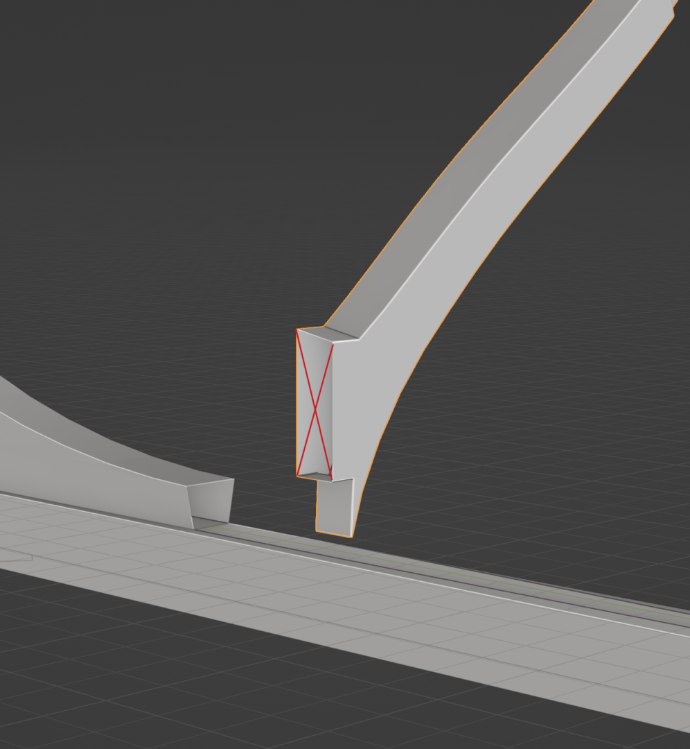
-
Yet Another Pandora 3D build
3DShipWright replied to herask's topic in CAD and 3D Modelling/Drafting Plans with Software
Looking good - a few questions/notes: Why do you have the front/back run of the ship spanning along the global x-axis instead of the global y-axis? Is this an Unreal import thing? (I'm fluent in Blender but I'm just starting my UE journey) Why is the AP station your origin and not the '(+)' (origin) station? Have you accounted for the 15in deadflat at midship? If done properly, figure D3/12 on page 64 of the AoTS book should either be copied twice at either end of the deadflat, or else another 7.5 inches should be added between the single center point and the nearest stations fore and aft, once for the fore stations and once for the aft. (this is the #1 thing I see most modelers get wrong with Pandora) Are you going to set the z-origin of your ship to the top (inner) rabbet line? There is no rabbet line 'washout' on Pandora and other Porcupine class ships as there are on swan class ships. Thus, I think the stairstep at the back most part of the keel is too long. It should only be as long as where the stem post sits on it. Have you accounted for the 'taper' of the keel fore of station 'N' and aft of station at the back rabbet line that allows the bottom (lower) rabbet to remain basically straight? TLDR; Pandora's keel construction is fundamentally different than Pegasus, and it took me months to get all the details correct. They are small but can lead to cascading issues later in the build if not addressed. Finally, and this is just idle curiosity - does the laying of the keel include the false keel? also, these parts are copper sheathed, so are you planning on texturing twice? Again, just curious... Anyway, off to a great start, -Nate -
Nate's PANDORA in 3D
3DShipWright replied to 3DShipWright's topic in CAD and 3D Modelling/Drafting Plans with Software
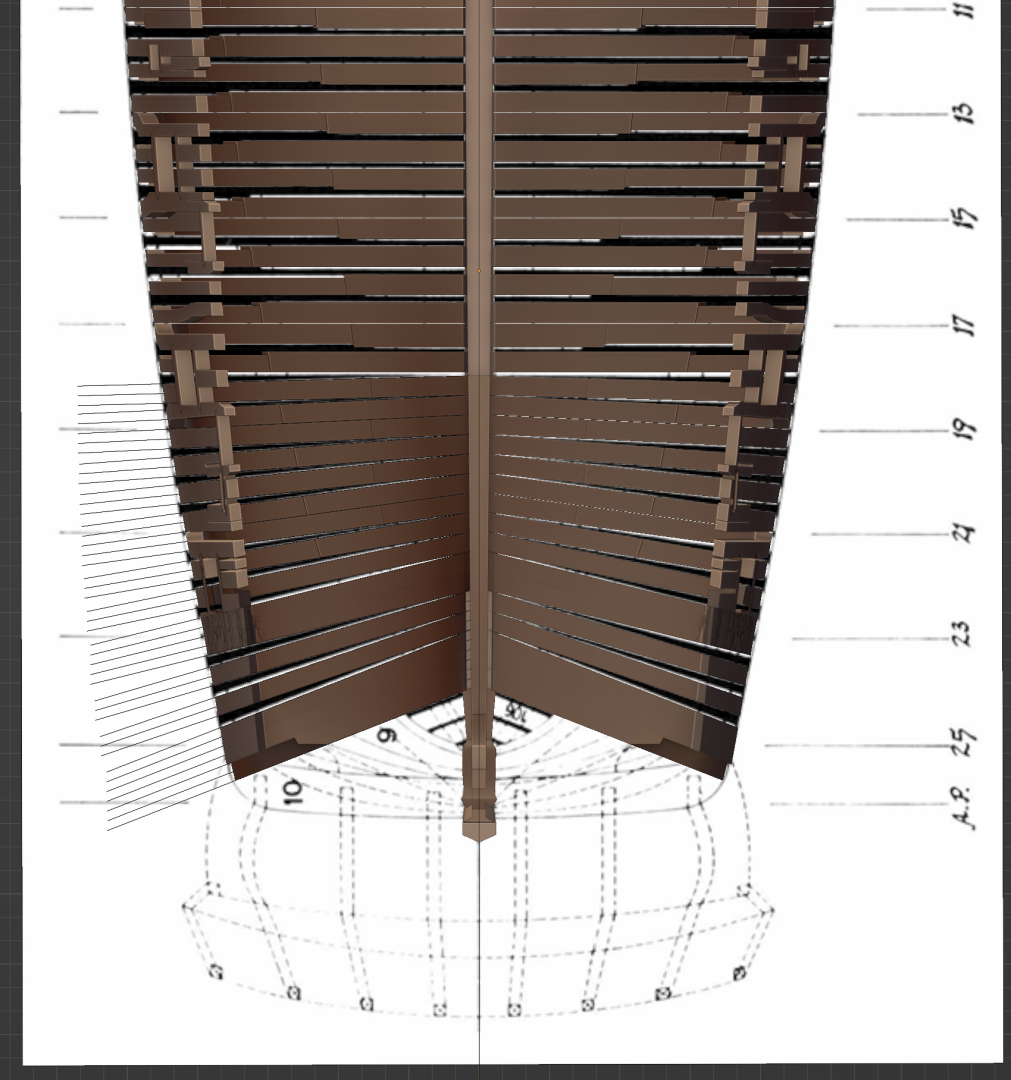
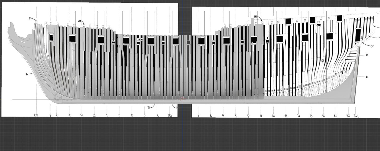
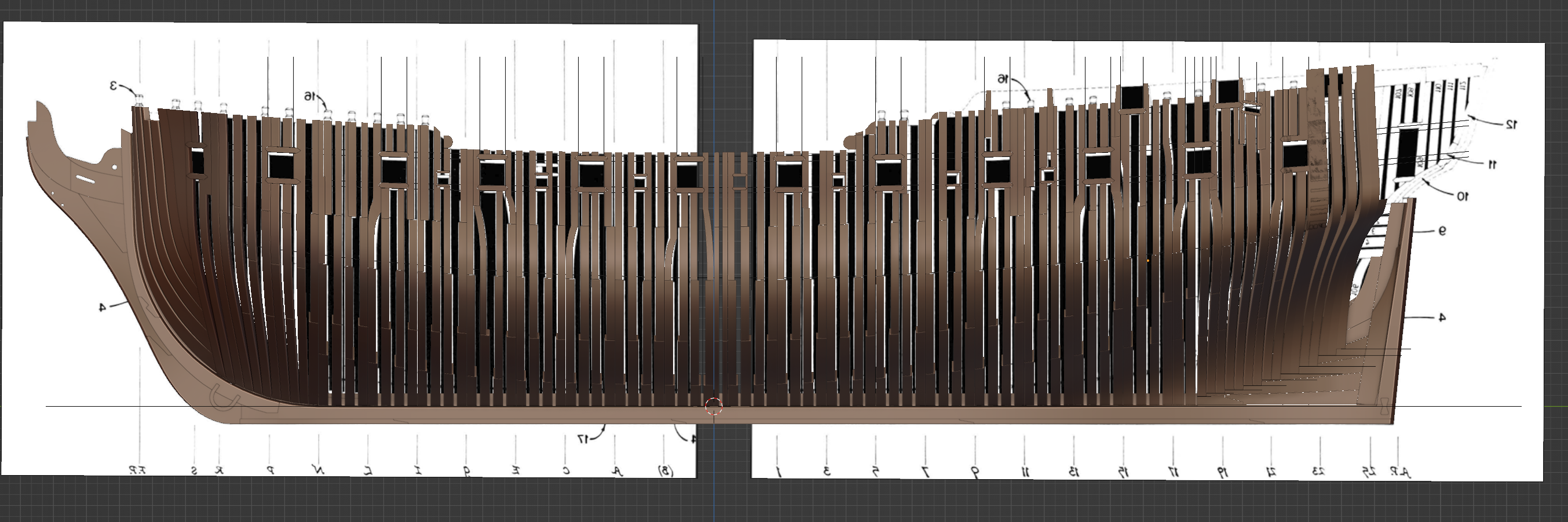
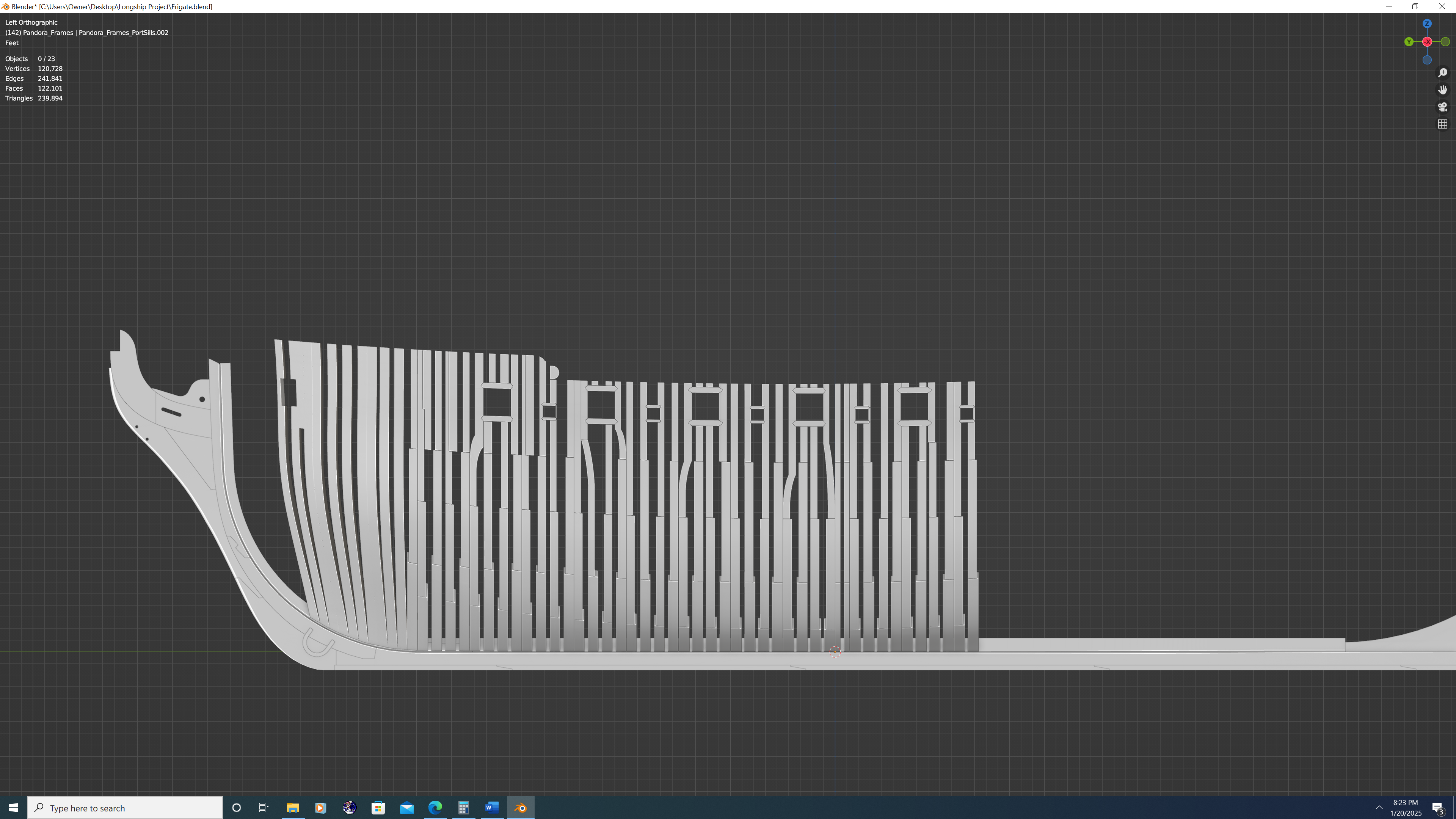
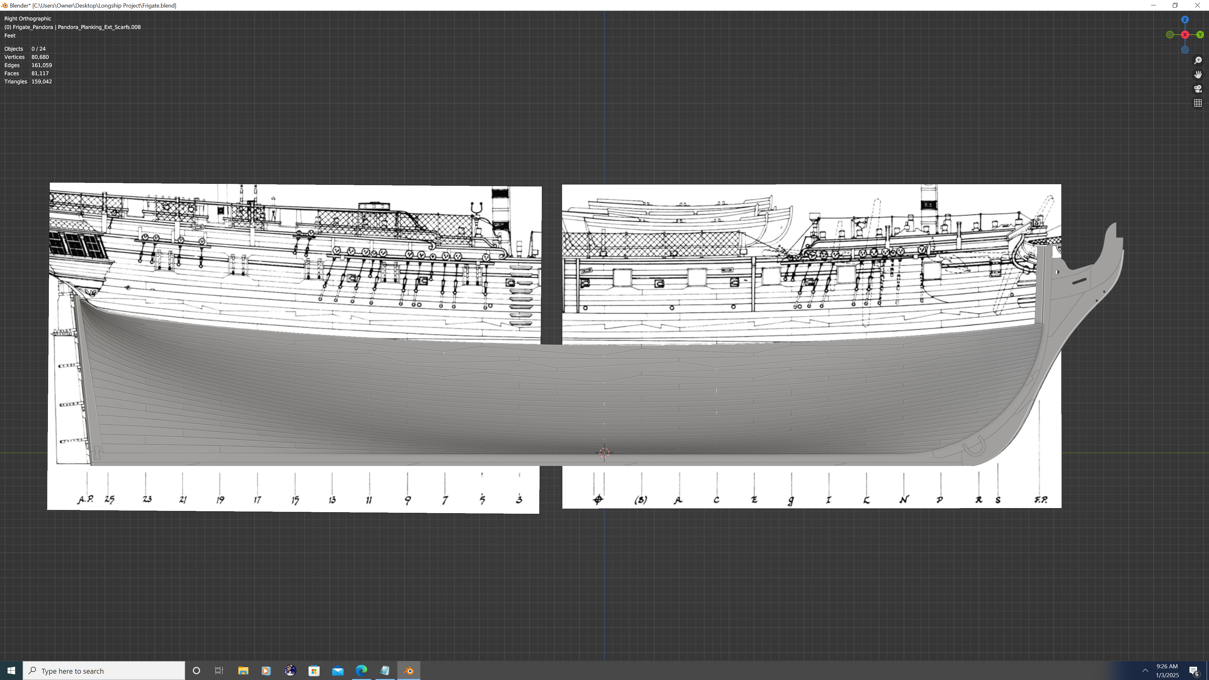
Hey folks, haven't posted in a while, so here it is... Frames are still progressing. Sadly, I don't have the same amount of time these days to dedicate to modelling as I used to, but I hope to complete the internal frames within the next two weeks, at which point I can move on to cutting out the internal planking. Building the frames - or at least the incredibly accurate way in which I'm doing them - is very tedious and slow. The good news is that once I'm past this step the rest of the build should pick up in terms of pace. And here's a screen shot showing how well my modelled frames align with the plans. Note - the height of the gun/sweep ports is correct. There is actually a very rare distortion in the AOTS book that caused the images to get squished vertically, whereas my modelling conforms perfectly to the RMG plans, as well as the scanting tables from The Shipbuilder's Repository. Best, -Nate
-
Yet Another Pandora 3D build
3DShipWright replied to herask's topic in CAD and 3D Modelling/Drafting Plans with Software
That Shipyard and Drydock combo looks fantastic! On the topic of which ship to do next, the obvious answer is that it is 100% your choice. My Personal preference, for selfish reasons, is that you continue with your Pandora. I don't look at it as competition at all, as I never intend to sell mine, and from what I've seen the group projects on this site tend to foster the best results among all participants. I think it be really cool to have two 3D artists reconstructing the same ship with the same software. On the flip side, if you did construct the Bounty, my Pandora could be there when your crew inevitably mutinies. Excited to watch whatever you decide, -Nate -
This is absolutely awesome The lines are soooo clean and precise. Keep it up, can't wait to see more!
-
Nate's PANDORA in 3D
3DShipWright replied to 3DShipWright's topic in CAD and 3D Modelling/Drafting Plans with Software
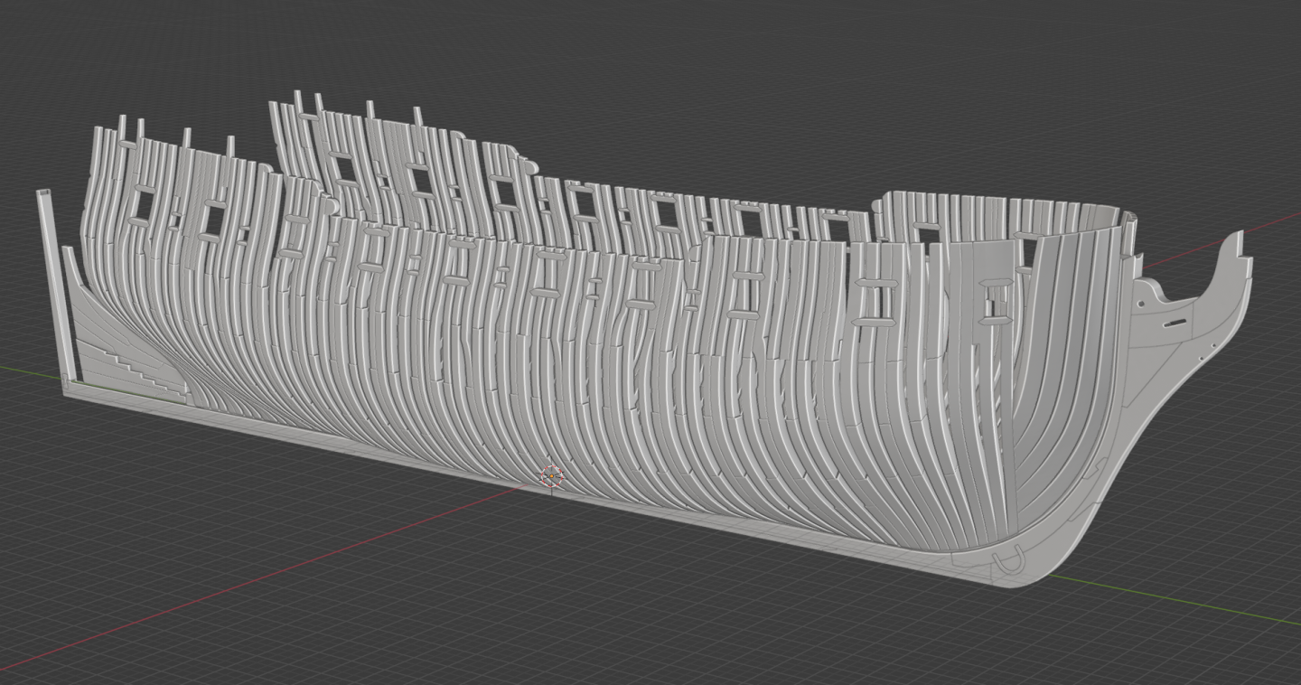
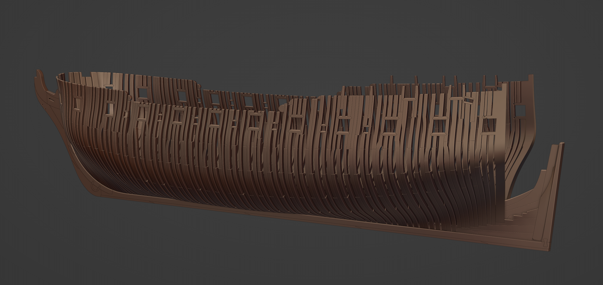
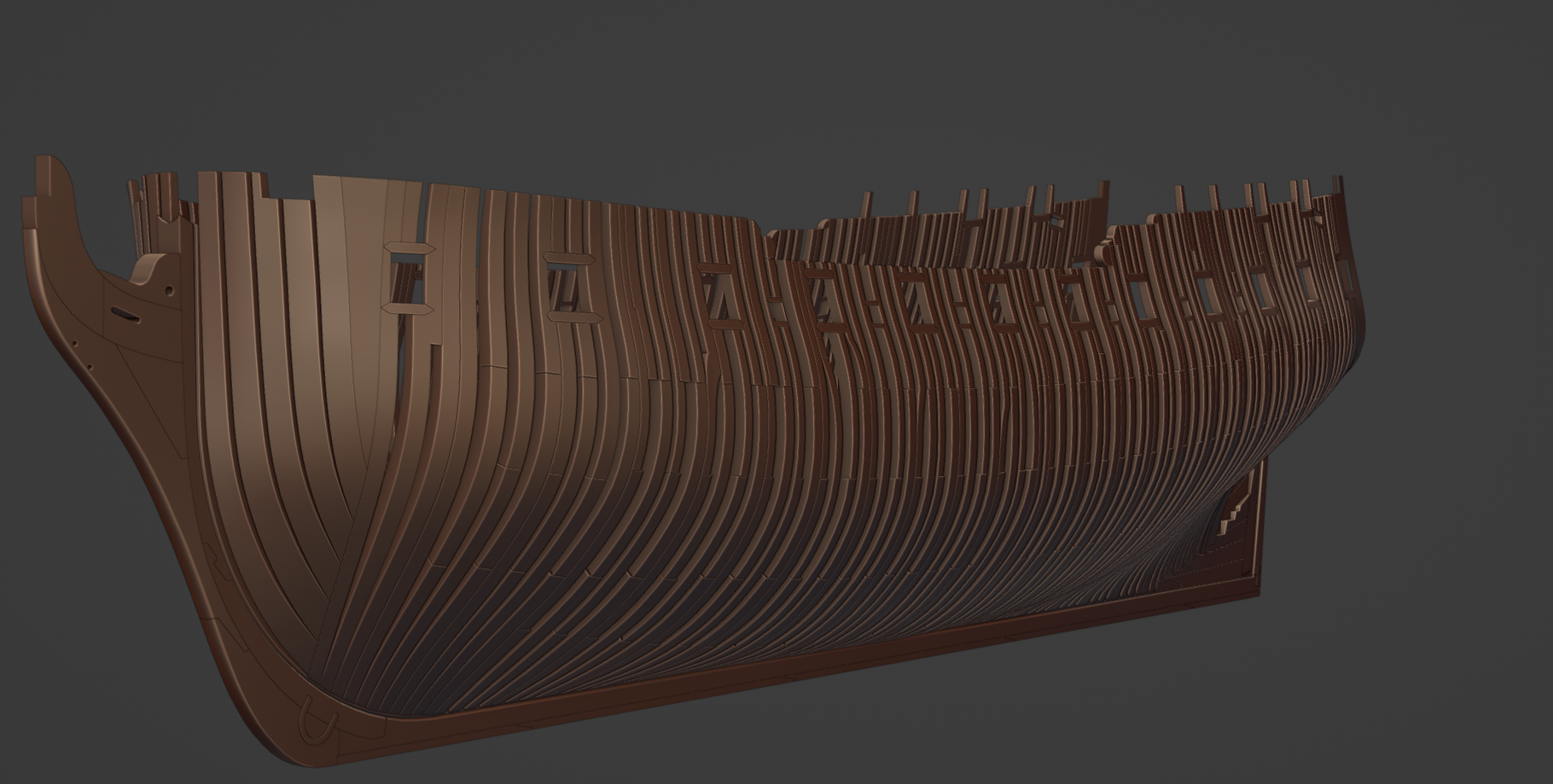
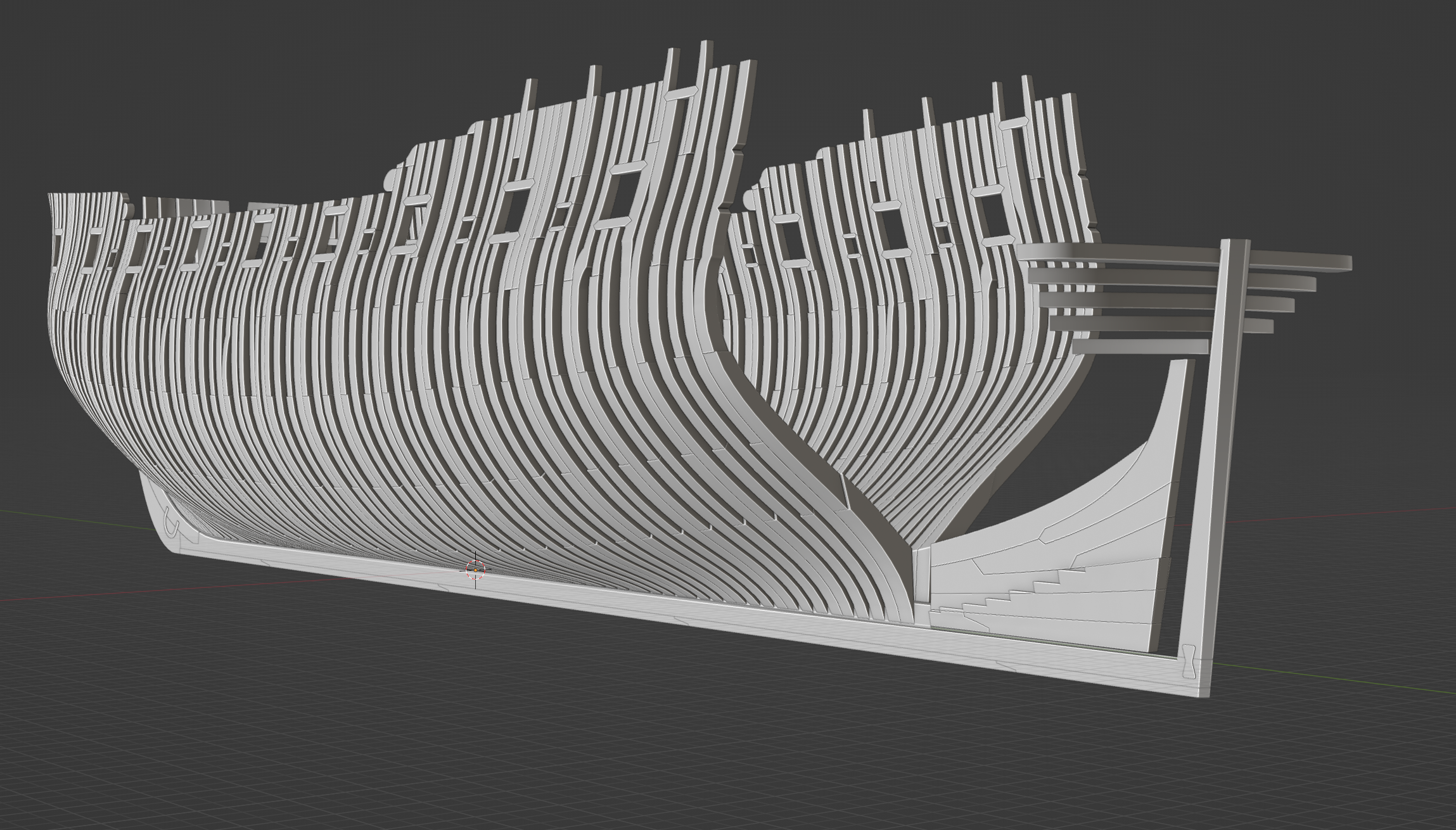
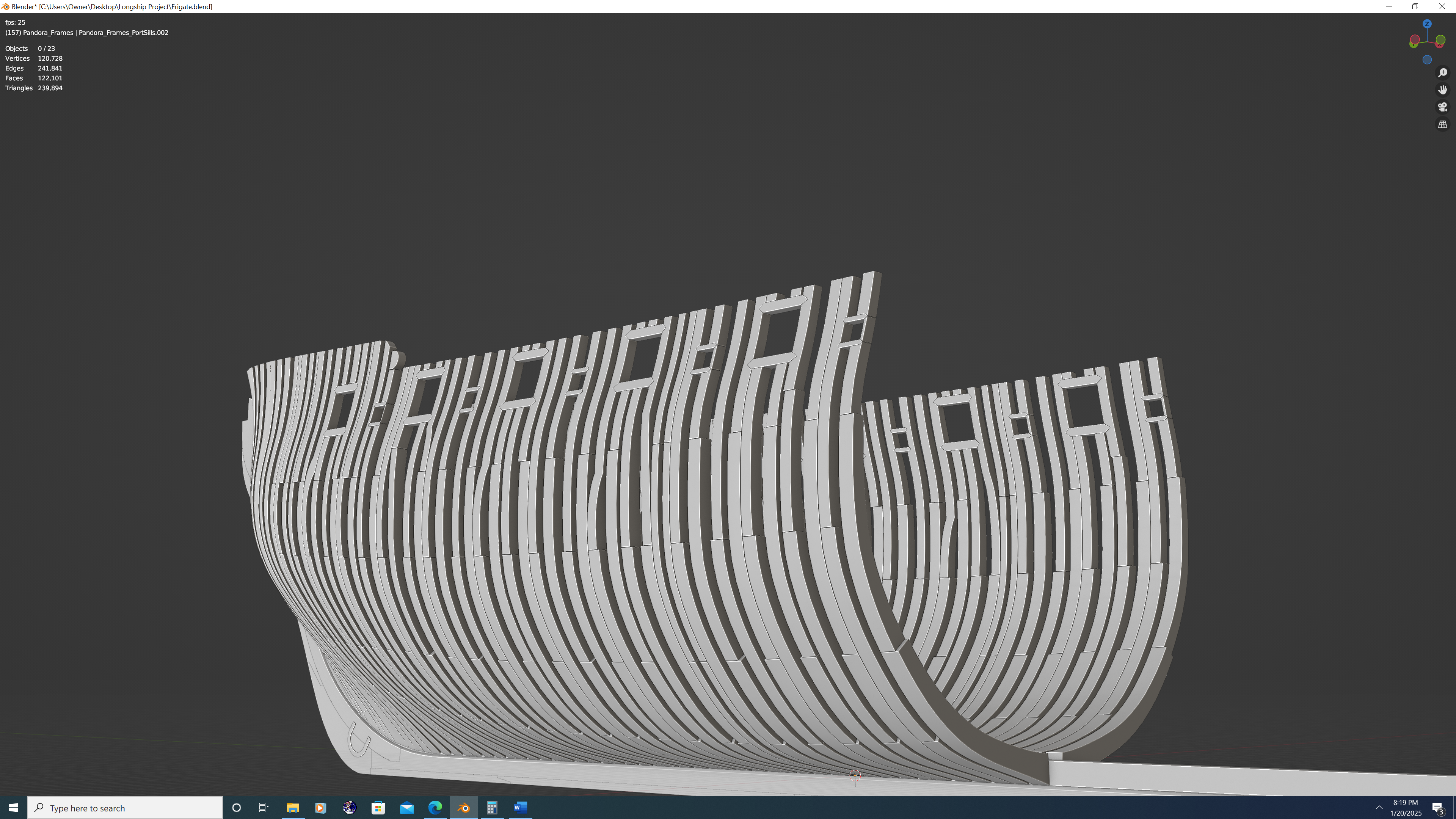
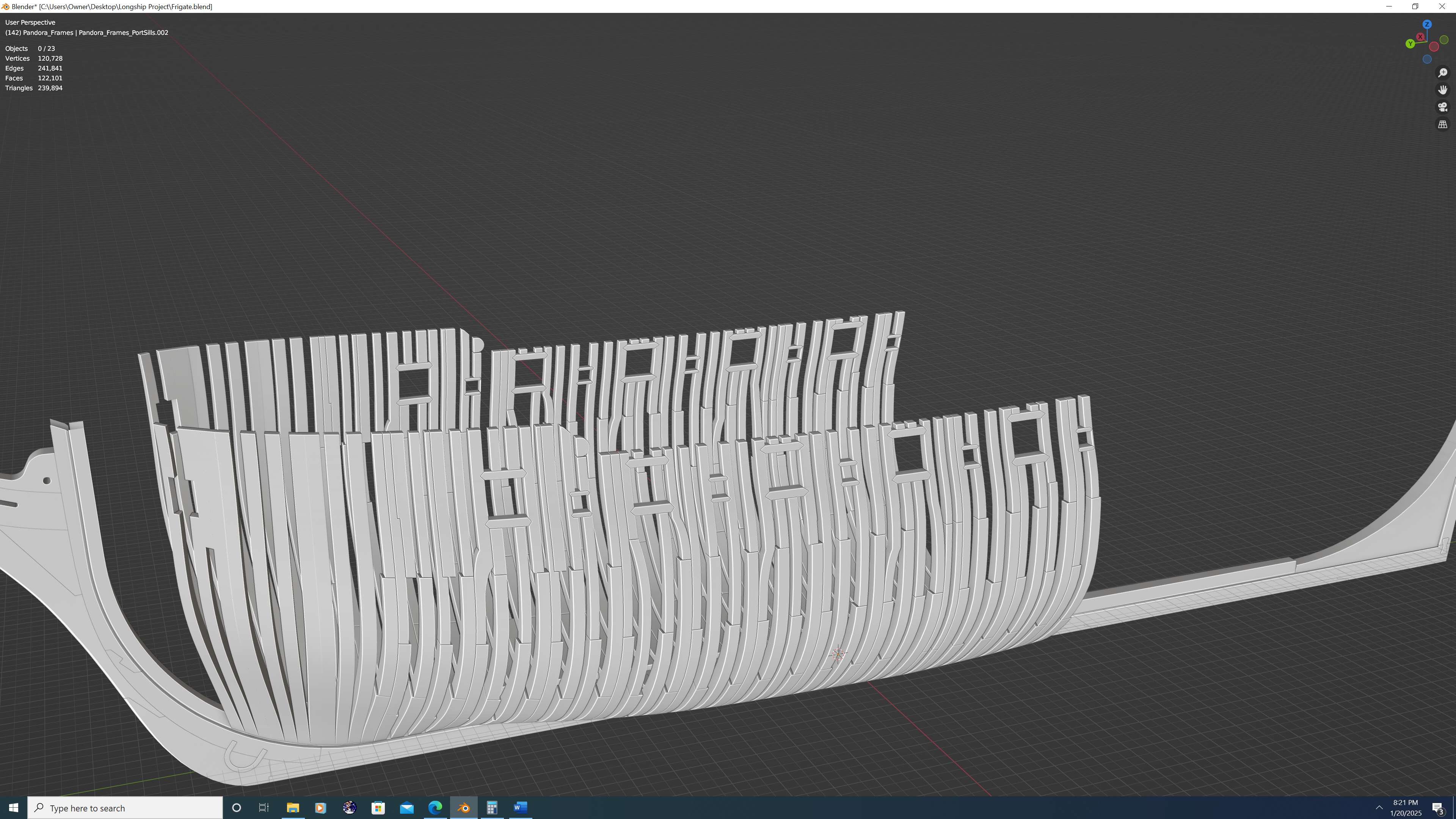
Pandora's framing, still very early stages. I have about 2/3 of the perpendiculars modelled, and now I'm working on the fore cant frames. Each futtock is extremely precise from the floor timers up through the top timbers, and each dither and bend mathematically in accordance with the scantling data in The Ship Builder's Repository This applies to: The room and space calculations provided The siding and gap dimensions taken from the 15in deadflat at midship, the other waist/midship stations (stations '5' to 'N') and outer perpendicular sections (5 in total). The dithering with each futtock above the floor - 5/6ths and 2/3rds, respectively The pattern of offsets and frame staggering and perhaps more importantly the specific points on the ship where these general rules were broken. Note: All chocks not currently modelled. They will be cut out from the existing frames and modelled later. And a couple screen grabs... Till the Next, -N.


-
Nate's PANDORA in 3D
3DShipWright replied to 3DShipWright's topic in CAD and 3D Modelling/Drafting Plans with Software
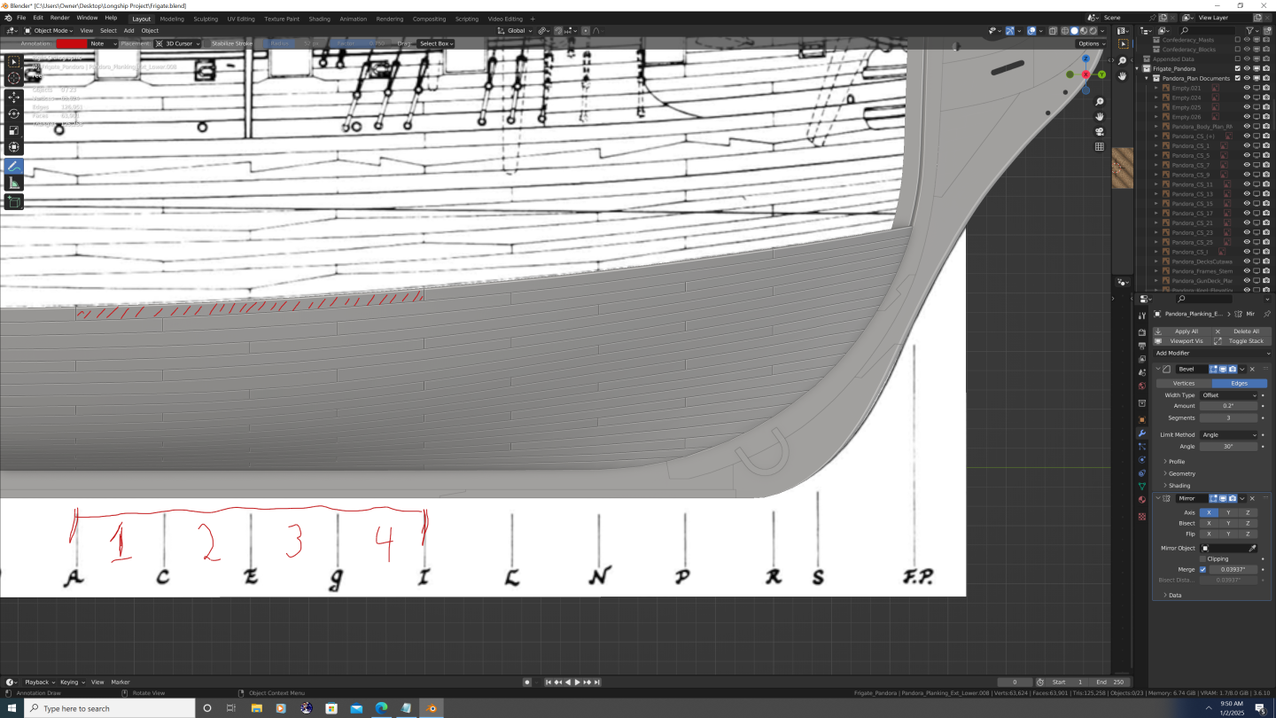
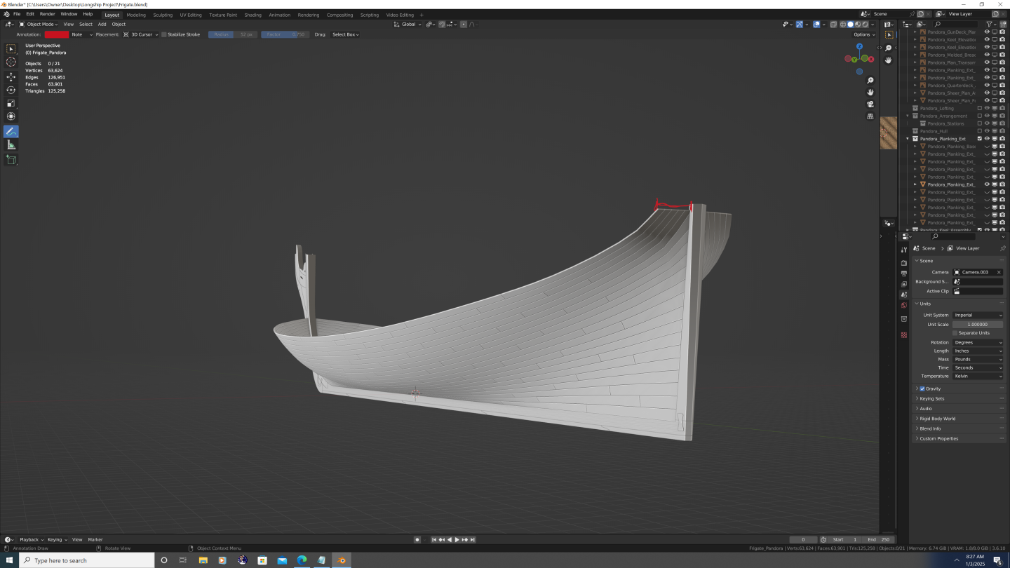
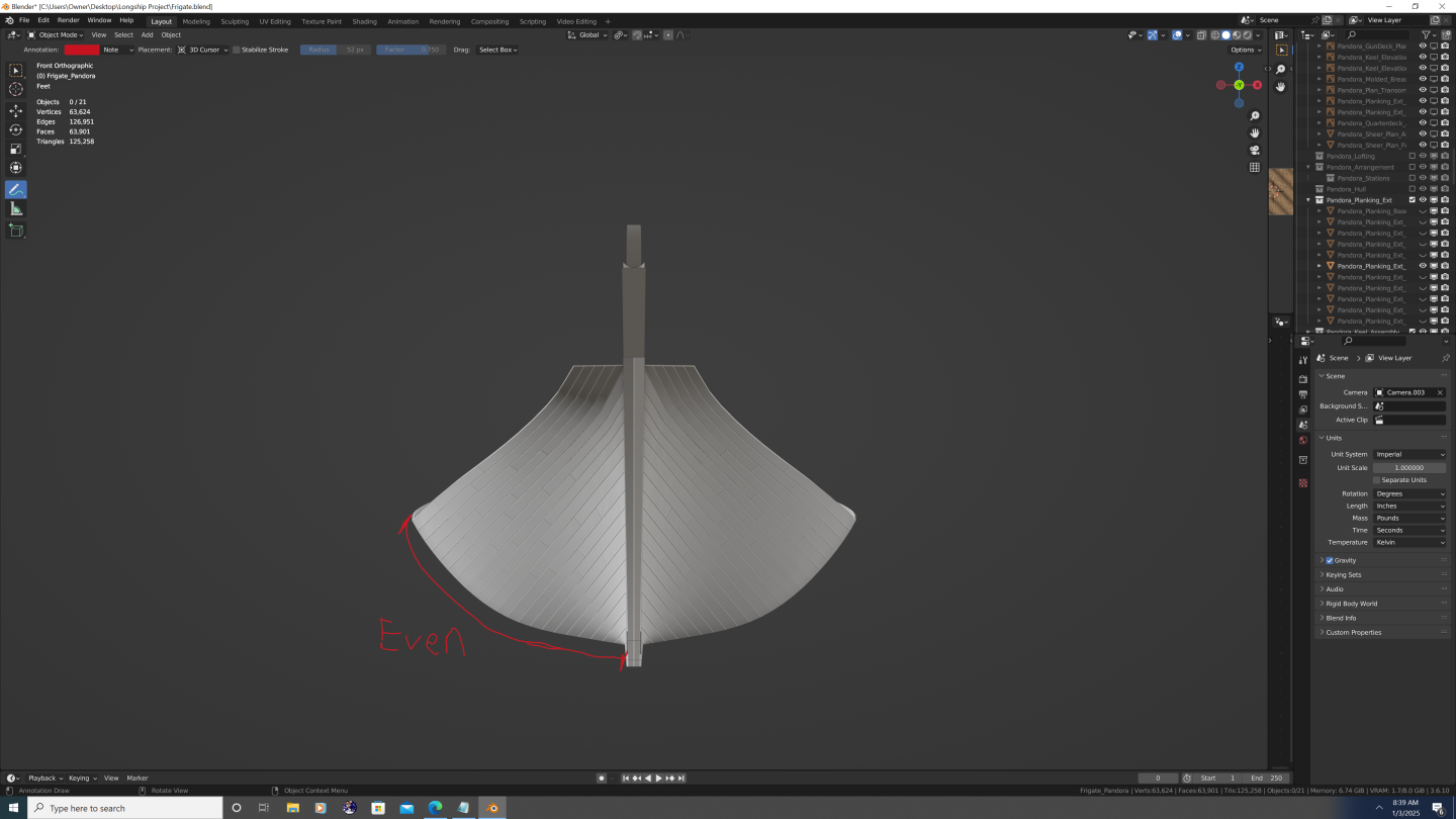
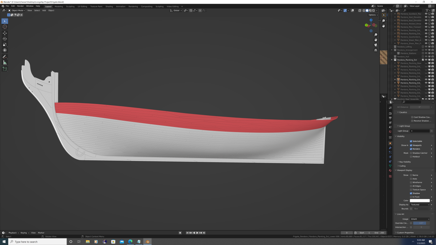
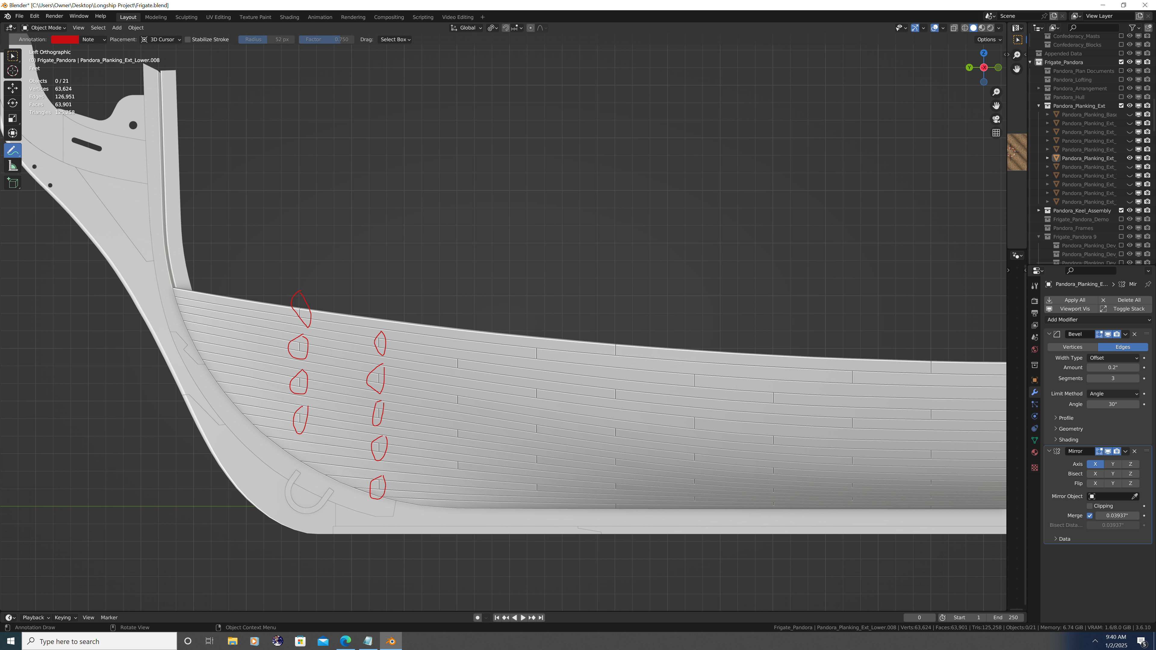
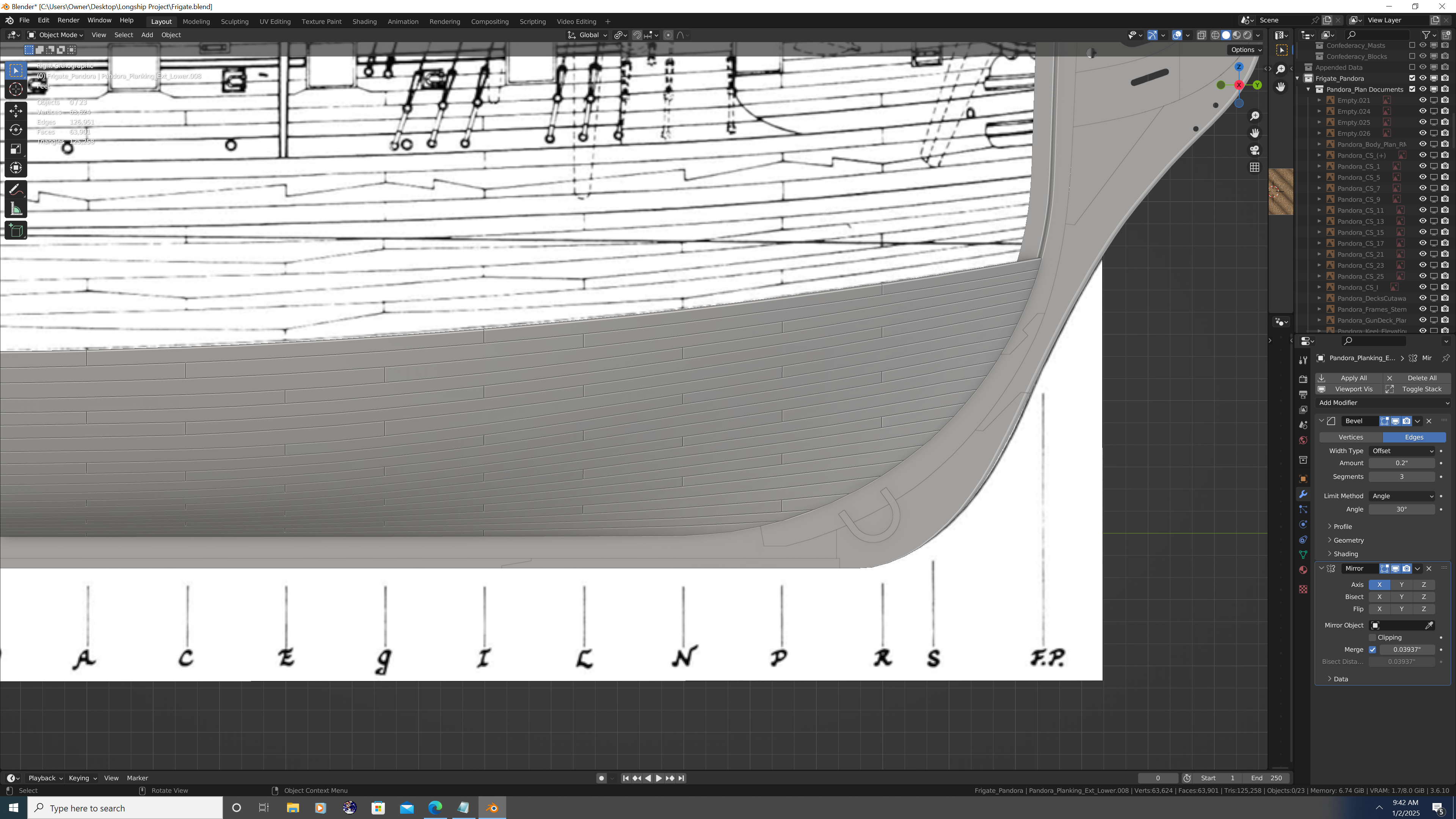
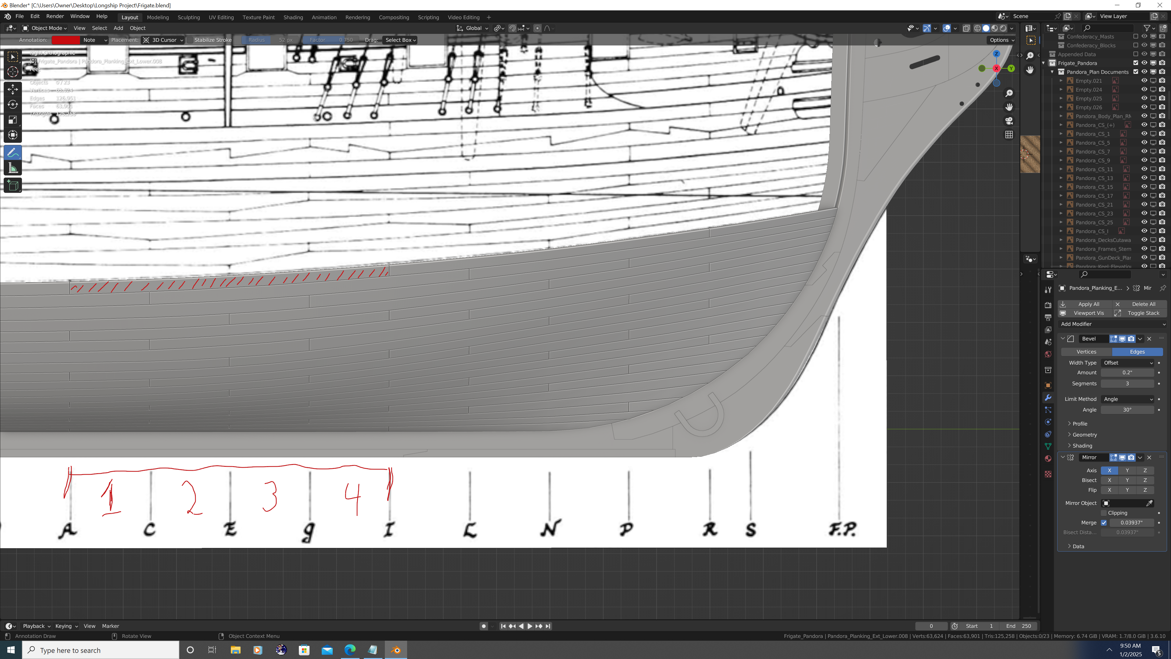
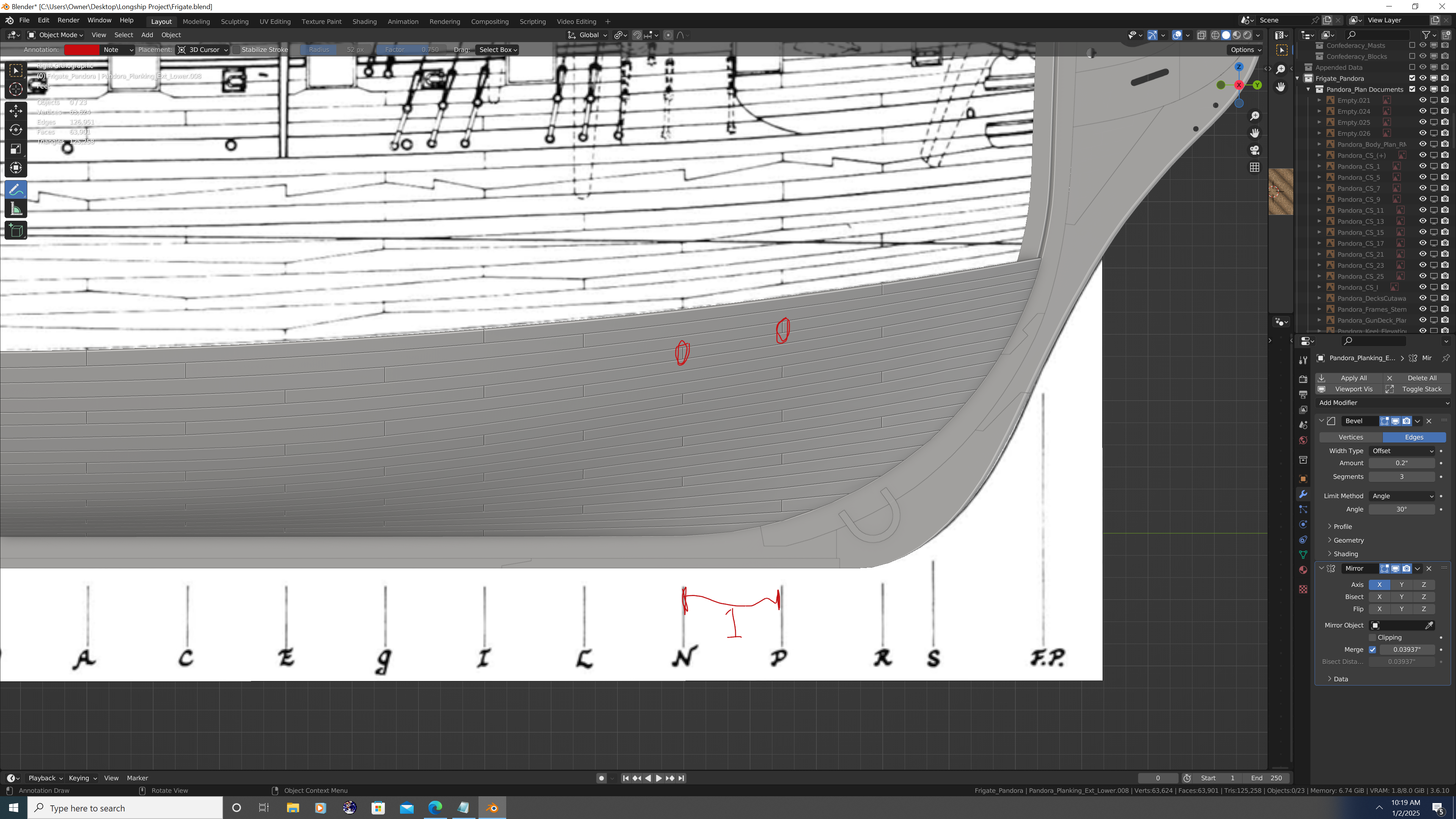
Hey Folks, Happy New Year! I'm excited to be back at the table on Pandora and now have new resources at my disposal that I hope will make Pandora my best project yet. The keen observer among you may have noticed that while I began this project in the traditional manner - that is, gathering/lofting plans, building the keel/stem/stern assemblies, and getting the moulded breadth 'shell' built in 3D - I then jumped straight into making the exterior planking and fittings. This probably leaves many to wonder what, if any, internal details I plan on modelling... Well, I'm happy to say that even in its digital form, this Pandora will be a 100% built up model. Every individual frame, beam, plank, nail, bolt, and sheet of copper will be captured in excrusiating detail. It is for that reason that I needed more books in my library. Now, thanks to my family, friends, and loving wife, I have acquired 4 new (old) titles that should help me do justice to this famous piece of Naval history. Among these, the famous Ship Builder's Repository of 1788, shall be indispensable for construction, dimensions, and put plainly: how it all fits together. With all that said, the reason I was working on the outside hull and fittings was precisely because I could work on these parts with relative confidence while awaiting the reference material to do better justice to the frames and interior of the ship. I've nearly finished the external planking and am pleased with the results for the most part. The 3-2-1 Pattern and the Rule of 4 The external planking on Pandora conforms almost exactly to the plans. Including the garboard strake, there are 21 'standard' strakes that follow the 3-2-1 pattern I pointed out in my Confederacy project. I know this confused some folks, so I'll do my best to explain how I interpret this pattern: There are a series of vertical cuts that separate each strake along the hull into individual planks (duh!) On Pandora and many other ships I've seen, these cuts are made almost exactly where the station lines are. Except where the planking is sheared off at the bow and stern, each plank is exactly 4 stations long Now, the 3-2-1 pattern, as I call it, refers to how the planking is staggered between strakes. It should actually be called the 'Alternating 3-2-1 Repeat-as-you-go-down' pattern. Yuck! But not to worry, it's simple enough to understand: Starting at the foremost cut in each section, move aft 3 station lines to get the location of the next cut in the strake below the one you started on. Next, move forward 2 station lines to cut the strake below that. Finally, move aft 1 station line and cut the plank below that. That's it! Just repeat the process until the whole hull or hull section is complete, using the same station line you started with, only 4 strakes down. This works out well, as every plank is 4 stations long, and every vertical cut in the planking is made 4 strakes above the last one. Hence, the Rule of 4. Hull Plank Sections: Section #1: Garboard -> Tuck -> Bottom of the Lower Counter The planking for the first 21 strakes on Pandora follow the method I described above, but even within this first section, the planks are not evenly spaced (i.e. equal siding width) across all station lines. The reason is the tuck The tuck at the stern is at the top of the16th strake. The 16 strakes are evenly spaced from the keel to the tuck... As are the 5 strakes that extend outward from the tuck to the diagonal scarfs that make up the next section of planking. Note that though equal in width to each other, these last 5 strakes are considerably narrower than the 16 that preceded them. Upon reaching the deadflat at midship, all 21 strakes are evenly distributed and continue that way all the way forward. When viewed from behind, the cuts from the sternpost and lower counter to their respective place at midship appear more or less as straight lines. FYI - right now the topology is only able to change at the stations, half-stations, and the FP/AP, so more subdivision between these lines will be required to get the strakes to delicately 'curve' as they approach the tuck and lower counter. I do plan on fixing this later - as I will also need this shape to be more accurate when I add the transoms. Section #2: Diagonal Scarfs -> Elm Stringer or lower Thick Part Next comes a series of 3, double-wide strakes (each being the width of 2 normal strakes, or 6 strakes in total). This part of the ship has the sharpest changes in inflection points along the station lines, so for structural reasons, each double-wide strake is cut into nibbed triangles (and inverted triangles), with each apex being 2/3rds the width of the total strake. The apex of each plank is also offset, so that one diagonal cut to the apex is 1 station long, whereas the other is 3 stations long. This way each plank is still 4 stations long. The direction of the offset also alternates between the three double-wide strakes. Note that there is also a 'washout' at the bow and stern where the cuts once again simply split the strakes in half. For the sake of simplicity, I set the washout points to align with the foremost and aftmost cuts on the rest of the planking which is at stations 'R' and '23', respectively. To be continued in next post...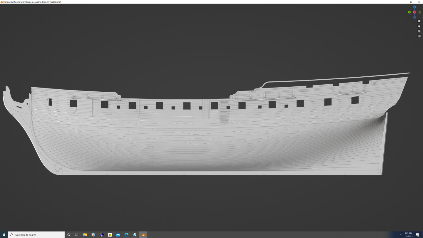


-
@Robska - Certainly! So the first thing to note - in case you missed it - is that the planks on Confederacy are actually 3D modelled (refer to pg. 1, post #27 of this thread to see how I made the actual planks). Basic Texturing Flow Pick a PBR texture you want to use, download the images, and setup your material node(s). [Not sure what your level of knowledge is with texture node setup in Blender, so feel free to ask myself or any number of the other Blender users on here to get you started if need be] For all the painted portions on Confederacy, I used the Worn Wood 3 texture from Textures.com Link: Worn Wood Surface - PBR0609 Ideally, you want a texture of a solid wood surface without planks already depicted in the texture itself. Conversely, if you are not modelling each individual plank or strake, then you may want to go with a texture that simulates the planking for you - just be aware that UV unwrapping the entire hull as a single island is going to be tricky if you want to minimize distortion. Next, UV unwrap the planks. I think for Confederacy I actually just used 'smart UV project' because I wanted more randomization and didn't want to mess with manually dragging them around the U editor window. However, manually marking the seams gives a cleaner result and is what I would suggest for a smaller boat/ship like yours. After you do the UV unwrap, scale the UV islands to their approx. real-world scale (tip - most PBR websites will indicate the scale of the texture on the download page). To get the painted look, simply replace the color file with an RGB input. That way, the texture retains all the AO, roughness, normal, and bump data from the wood texture, but you can easily make it any color you want. It also saves memory when you duplicate the material to get different colored wood, because the same images underpin all painted wood textures on my boat. This greatly reduces the workload because now the only time you need to use other PBR textures is for any non-painted wood, metal parts, and ropes. Once you get your basic textures setup and applied, let me know and I can give you more pro-tips, like edge wear, peeling looking paint, water/rust streaks, etc. Hope this helps, -Nate
- 107 replies
-
- 1
-

-
- Frigate
- Confederacy
- (and 1 more)
-
Nate's PANDORA in 3D
3DShipWright replied to 3DShipWright's topic in CAD and 3D Modelling/Drafting Plans with Software
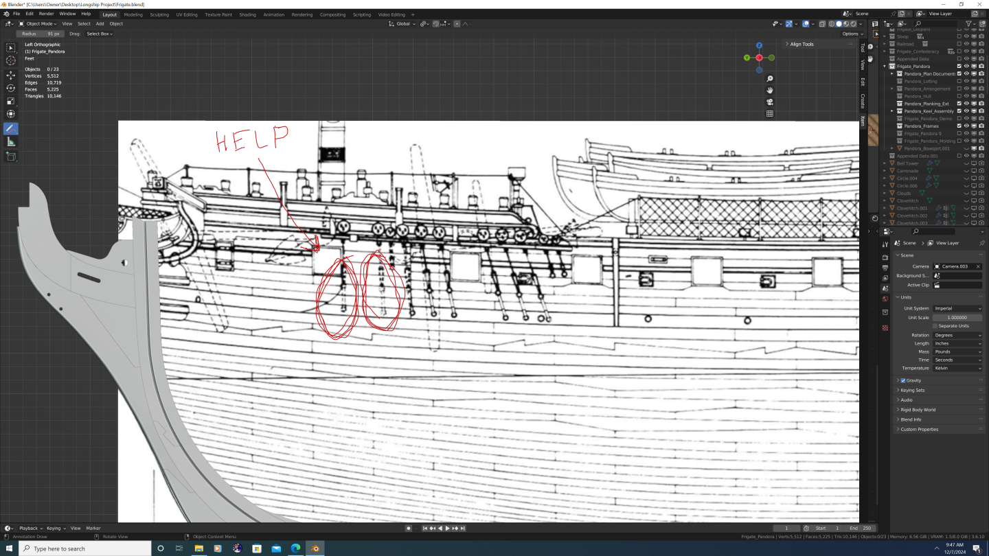
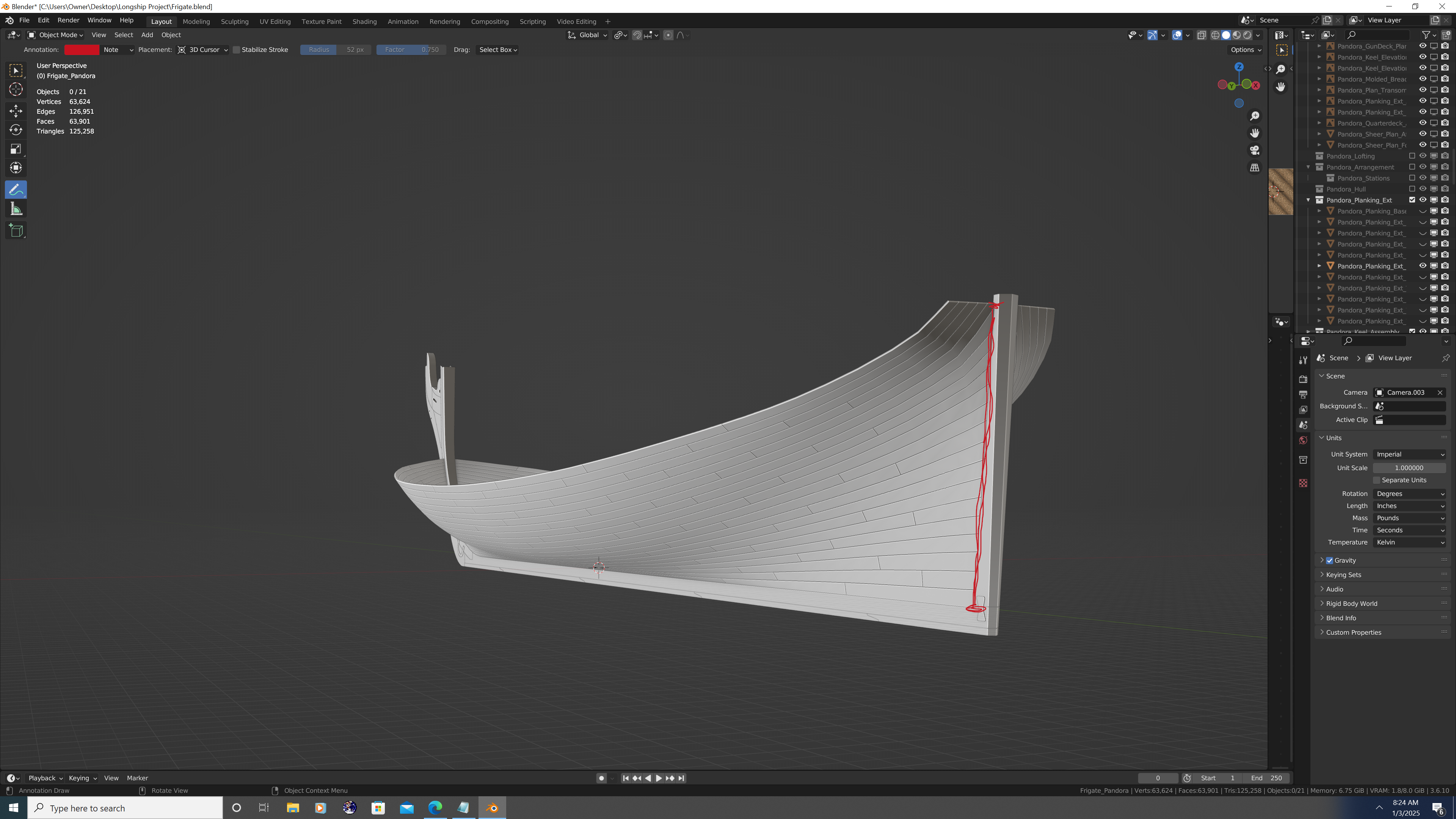
Here's the latest from pandora. The billboard needs to come in at a sharper angle so I'll have to fix that. Thing is - the plans show two of the chain plates affixed to the hull behind the billboard, yet the plans also show the first three planks of said billboard affixed to the outer planking. That seems like a physical impossibility - am I missing something??? Are there vertical grooves cut into the inside of the first three strakes of the billboard to allow for the chain plates? Thanks in advance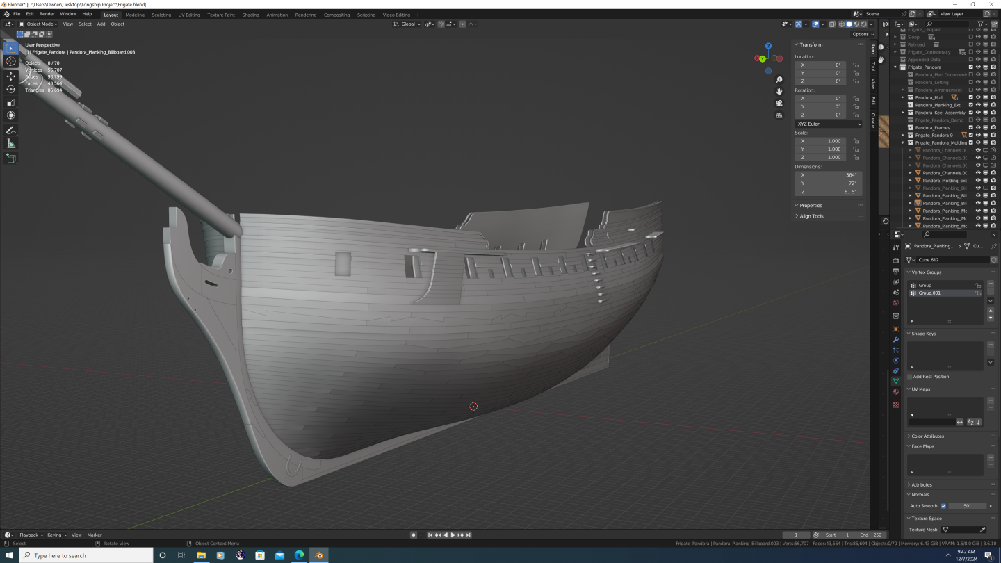

-
Nate's PANDORA in 3D
3DShipWright replied to 3DShipWright's topic in CAD and 3D Modelling/Drafting Plans with Software
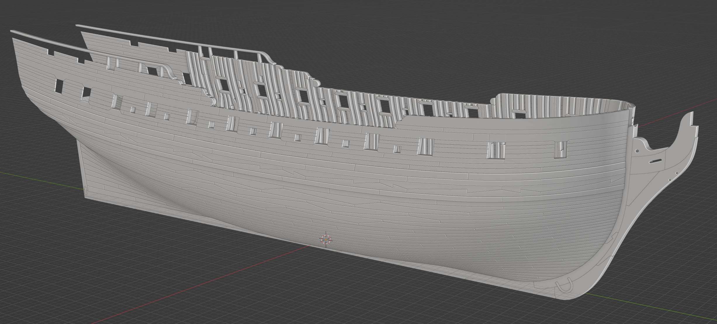
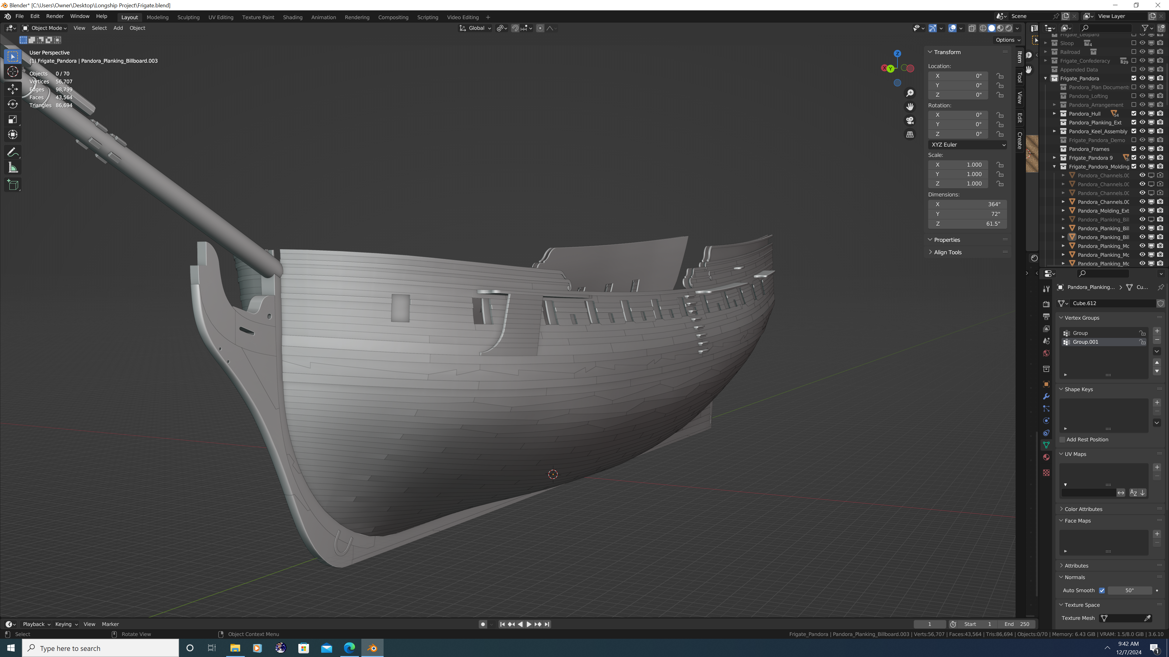
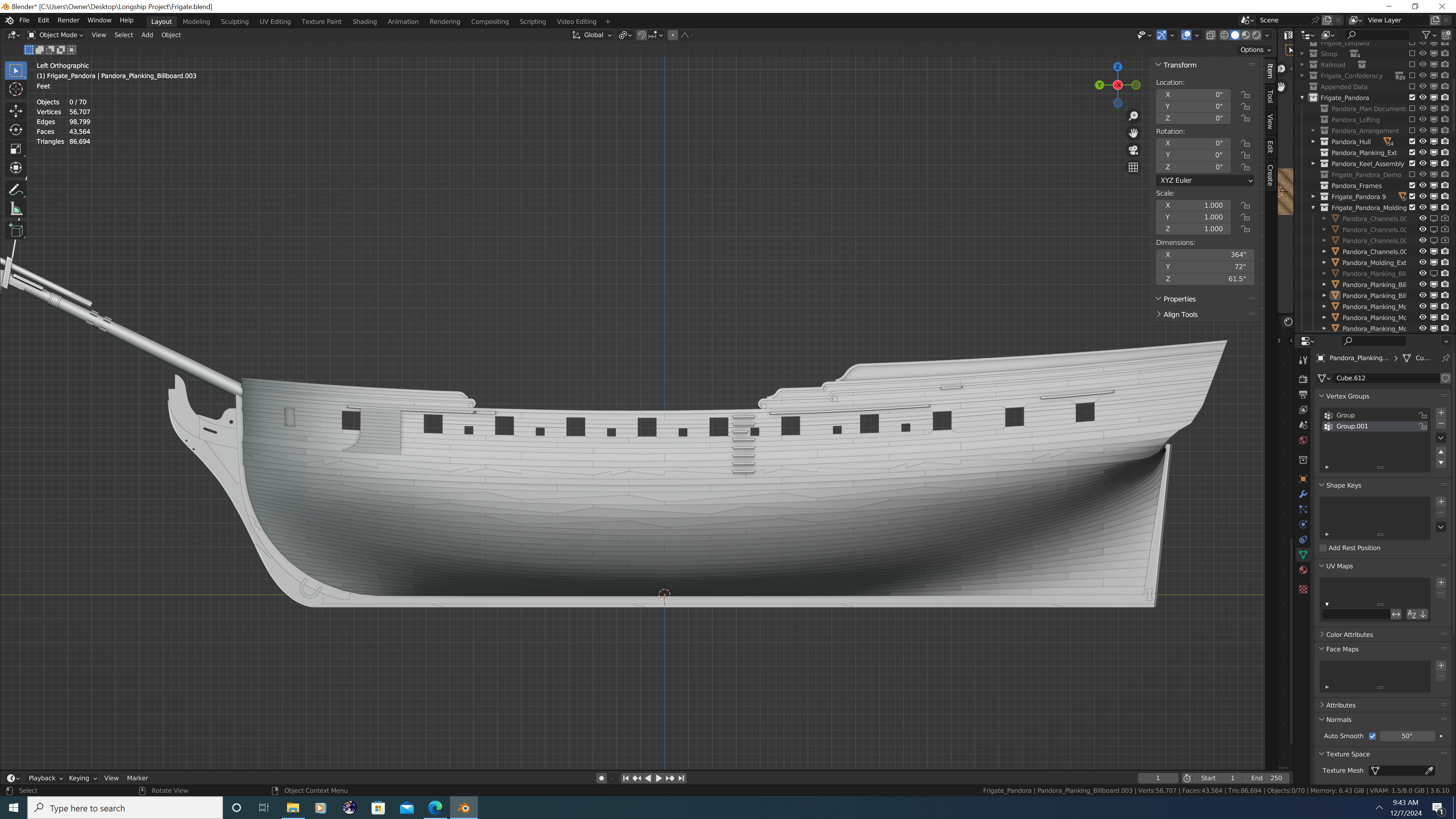
Outer planking nearly complete. I have one more rail on the forecastle to model, then its on to the channels, fenders, quarter deck cut-outs, and so-on.
-
Swan class 3D model in progress
3DShipWright replied to dvm27's topic in CAD and 3D Modelling/Drafting Plans with Software
Add additional vertices to your pin group, or just bite the bullet and set up the ropes as collision objects - that's what I did. I hate to say it, given that the rest of your model is so impressive, but to my eyes your sails are a bit of a let down. The textures and subsurface effects are good, but they don't behave like real sails. Here's a few tips: Make sure your sails are high poly (remember to use simple SS, not catmil-clark) and add the solidify mod after you run the simulations Run a different cloth simulation for each sail, or at the very least, apply the physics simulation at a different point on the timeline for each sail Animate the force field - real wind is not constant, changes both direction and speed. For extra realism, I added a low value to the verts in front of the bunt lines so that the sail billowed out around the lines somewhat. Note that this will require you model the ropes on each side independently (no more mirror mod, sadly, but the result is worth the extra effort. Finally, consider modelling the course sails as furled, Not only will this add to the realism, It also allows more of the actual ship to be seen in renders.thumb.png.58943c100079a995ccc530ffdac7130b.png)
.png.915fb8430dcf24a526758768692628bf.png)
- 141 replies
-
- 1
-
-
- pof swan series
- swan
- (and 1 more)


.png.c14d543f0cc2f39b0f5f19014277b8a6.png)