HOLIDAY DONATION DRIVE - SUPPORT MSW - DO YOUR PART TO KEEP THIS GREAT FORUM GOING! (Only 53 donations so far out of 49,000 members - C'mon guys!)
×

Herby63
-
Posts
142 -
Joined
-
Last visited
Content Type
Profiles
Forums
Gallery
Events
Everything posted by Herby63
-
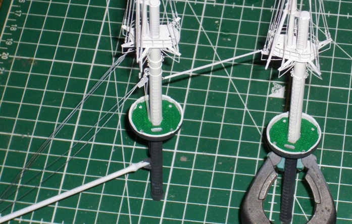
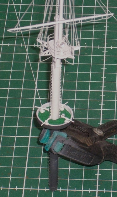
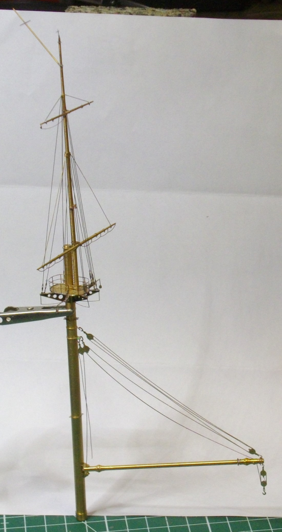
 It shouldn't come as a surprise that het fore mast comes next. The lower mast is secured by 10 shrouds. The fore topmast stay is held tout by a clamp. In the next update will be shown where it is belayed on the fore deck. Untill then, enjoy modeling.
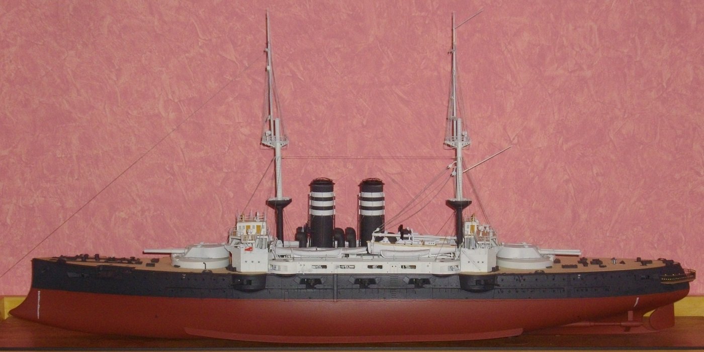
- 146 replies
-
- 2
-

-
- Mikasa
- Merit International
- (and 1 more)
-
4 stays (0,1 mm black thread) are atached to the ring just under the gunplatform and lead to the belaying points on the boatdecks. 8 stays secure the upper part of the lower mast to the aft bridge. Thus the main mast is erected. Some blackened lids were added to the boatdecks as well. The upcomming holidays should alowe me to make further progress. In the meantime, enjoy modeling.


- 146 replies
-
- 4
-
-
- Mikasa
- Merit International
- (and 1 more)
-
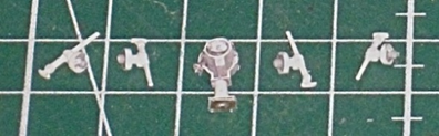
Time to put some deckfurniture on the bridges: - compasses, - communicationtubes, - searchlights, - small caliber armament. Until the next update, enjoy modeling, and thanks to my followers for the support.

- 146 replies
-
- 4
-
-
- Mikasa
- Merit International
- (and 1 more)
-
Thanks for the kind words guys, and indeed, she is turning into a lovely lady. Especialy after I grounded and painted the railings with Insigna White and mounted them on the fore bridge with some diluted PVA-glue. and the ladders, and on the aft bridge raillings. In this process 2 ladders got "lost". Afterwards I realised that Merit has provided these ladders too, so they will be added with the next batch of goodies. In the meantime, enjoy modeling.
- 146 replies
-
- 4
-
-
- Mikasa
- Merit International
- (and 1 more)
-
Thanks for the kind words and the empathy, Jeff, but who is Jolle?
- 146 replies
-
- 2
-
-
- Mikasa
- Merit International
- (and 1 more)
-
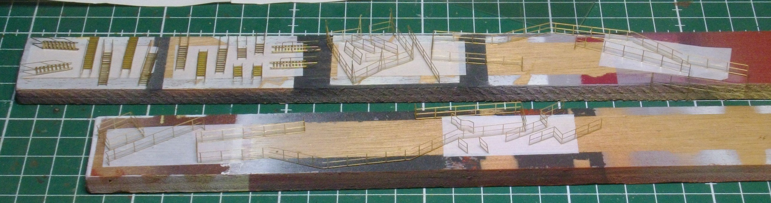
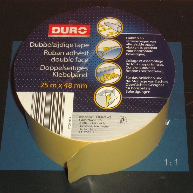
Hi Harald, Thank you for the advice, I shall keep it in mind for a next project. The tape I use is from DURO I am quite pleased with it, just dont leave the pieces too long on it, or you can cut them loose with a knife 😱 And the next job requires just some of that tape ! Before installing the masts, the bridges ans boatdecks must receive some details. I collected and bent all pieces necesary. Until next update, enjoy modeling 😀

- 146 replies
-
- 6
-
-
- Mikasa
- Merit International
- (and 1 more)
-
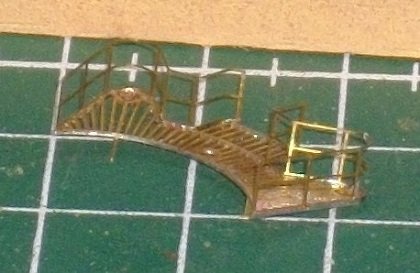
Before finishing the funnelstays I placed 4 laddders to the fore funnel platforms. See you in the next update.
- 146 replies
-
- 5
-
-
- Mikasa
- Merit International
- (and 1 more)
-
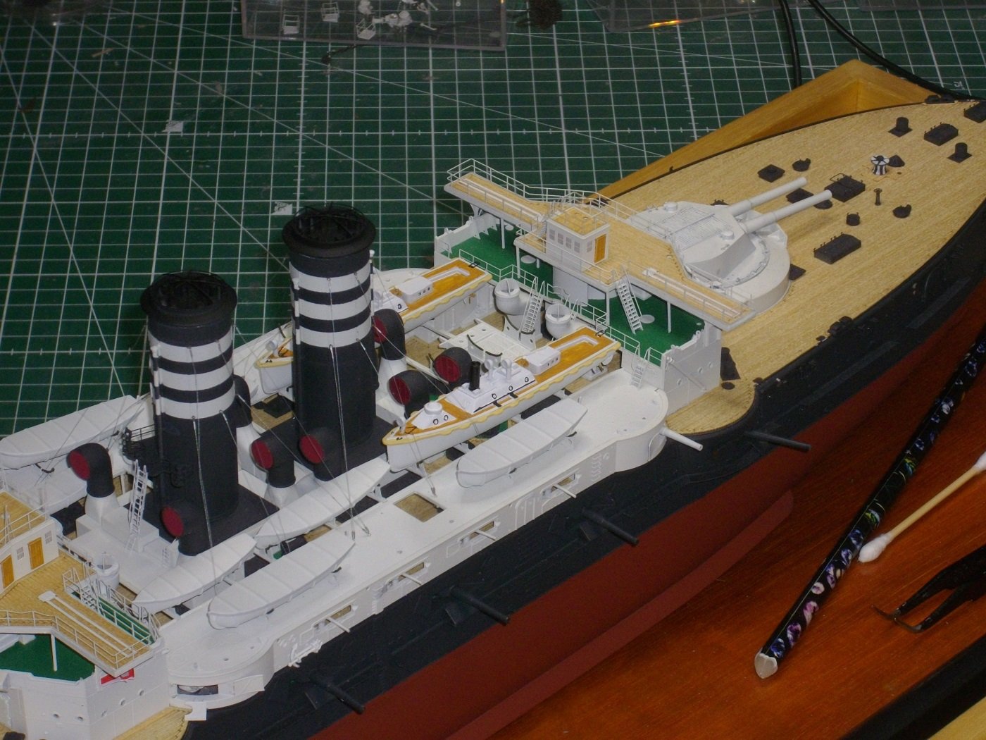
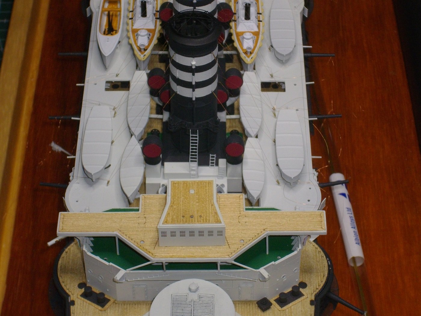
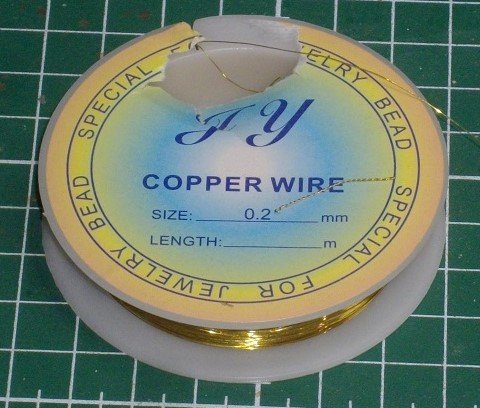
All stays attached to the funnels After drilling some 0,4 mm holes in the boatdecks and inserting eyelets made from 0,2 mm brass, I connected the stays to the decks. An other piece of microtubing allowed to make the stays to measure. A tiny amount of superglue was applied to the microtubing . After cutting off the excess wire, I painted the stays with Vallejo Model Air 71.065 Steel. I thank my dear followers for hitting the like button, an hope you enjoy the show. 🤩

- 146 replies
-
- 5
-
-
- Mikasa
- Merit International
- (and 1 more)
-
On to the next hurdle 😁 I testfitted a 0,056 mm brass wire with some microtubing with an external diameter of 0,4 mm. In order to establish where the belaying points should go on the boat decks, I placed the boats. One thing is shure, The present day attachment points are not realistic with the ships boats in place. Keep on modeling.
- 146 replies
-
- 6
-
-
- Mikasa
- Merit International
- (and 1 more)
-
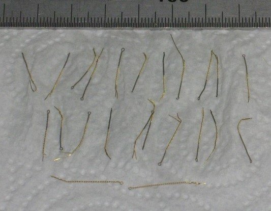
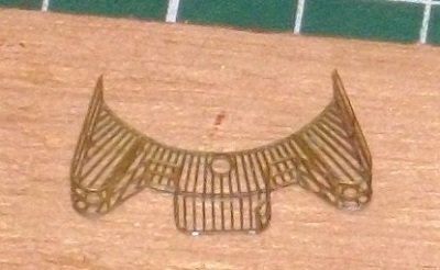
In this episode I shall start scratchbuilding the funnelstays. which are not provided for, neither by Merit, nor by Pontos. At first I shall have to provide for some kind of attachment at the funnels themselves: - I drilled 24 0,4 mm holes; - 24 eyes turned out of 0,2 mm brass wire; - After burnishing the eyelets, I shortened them, inserted them in the holes, and sealed them on the inside with a dot of PVA-glue Kind regards,
- 146 replies
-
- 6
-
-
- Mikasa
- Merit International
- (and 1 more)
-
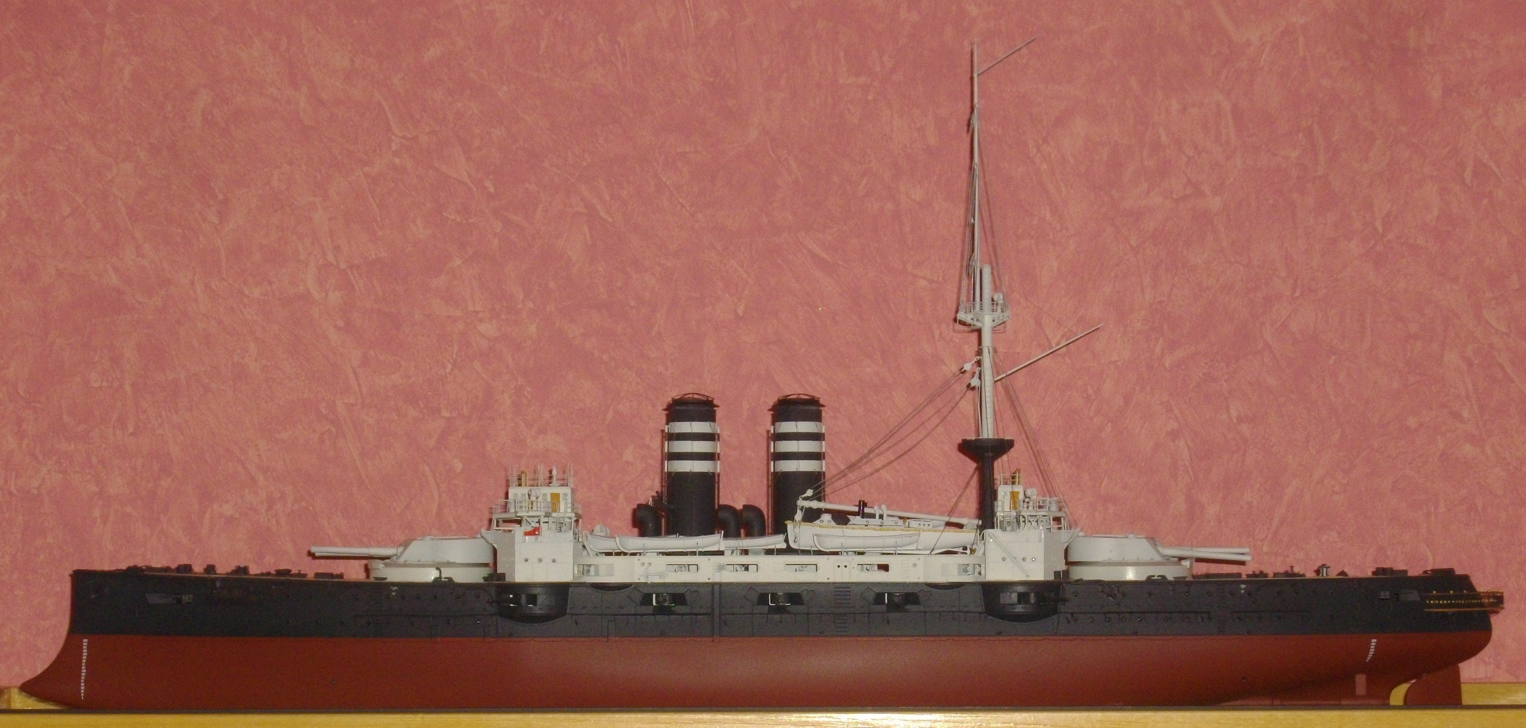
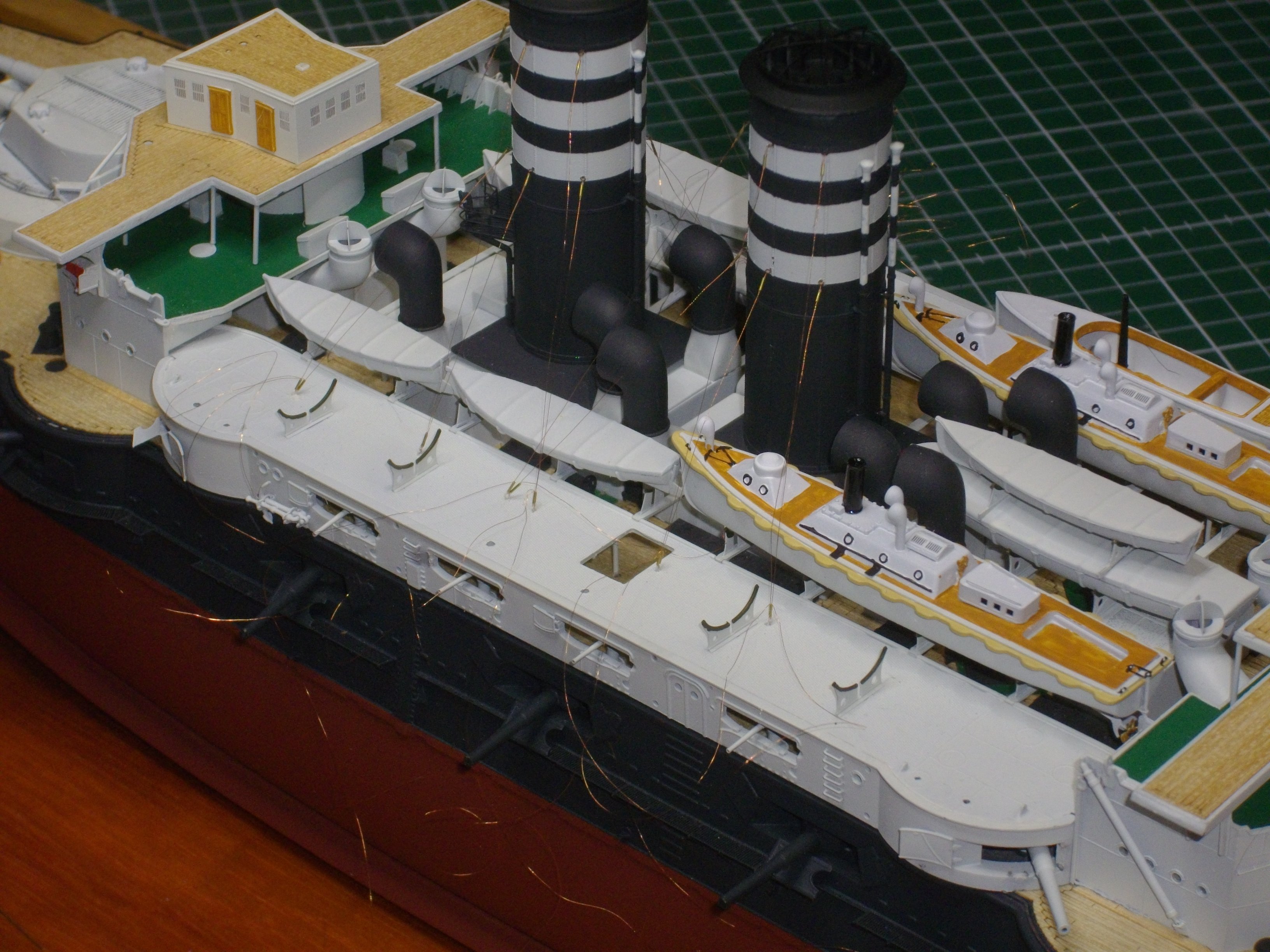
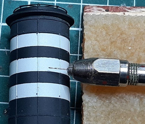
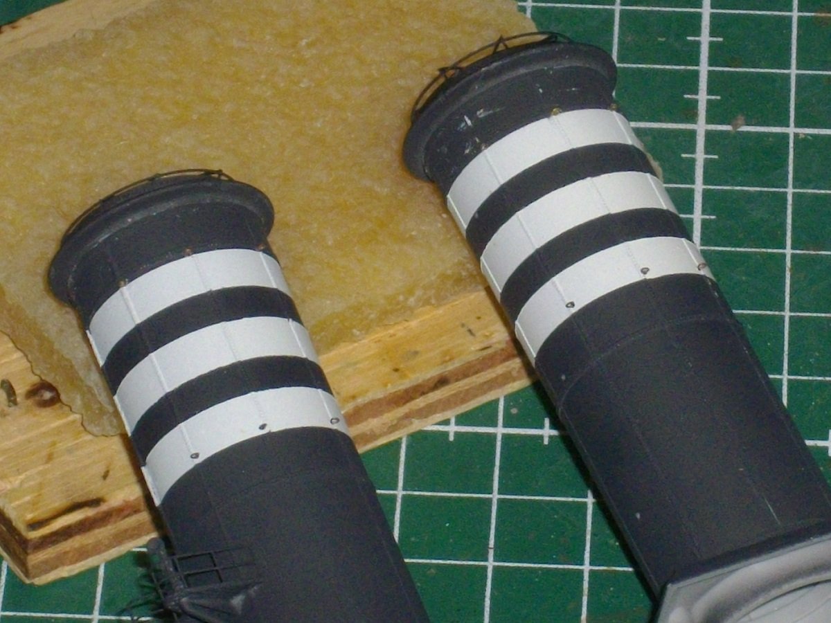
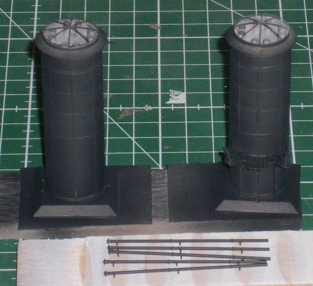
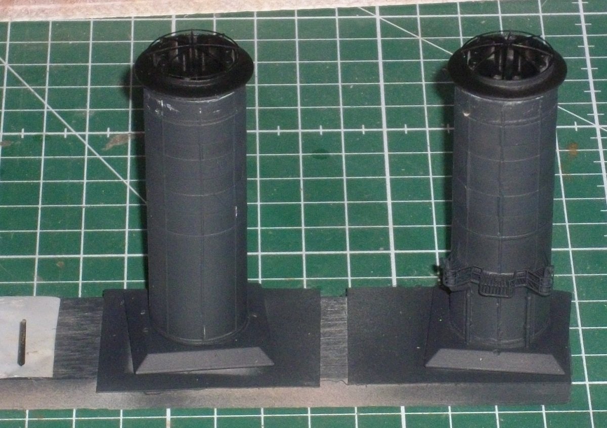
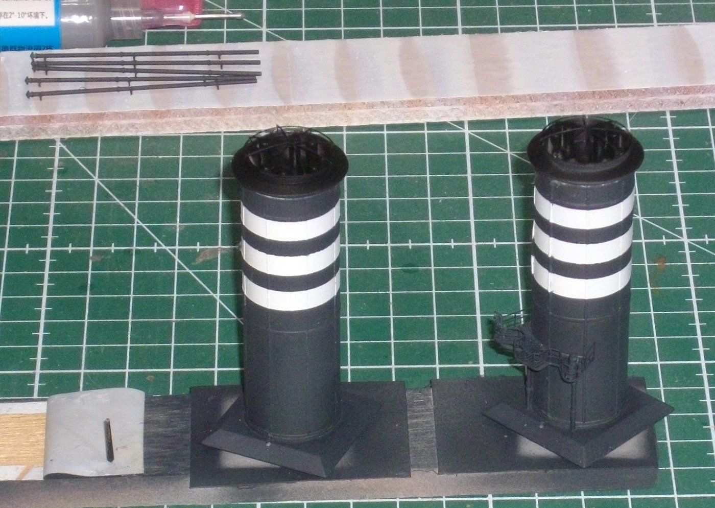
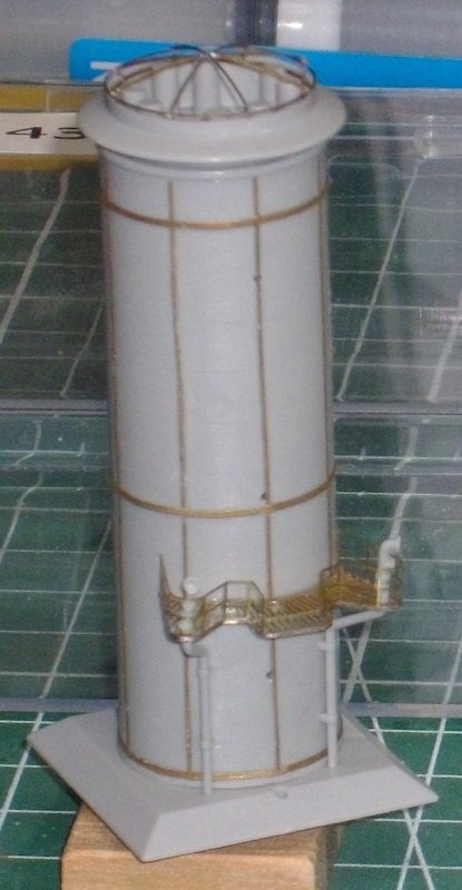
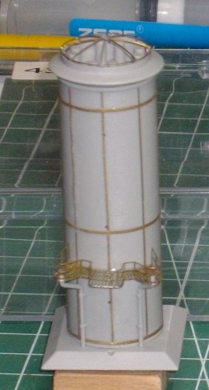
I masked off the 3 white stripes on each smokestack with tape cut to size. Then I painted them Black grey. Then I masked off the smokestacks to prepare them for airbrushing the funnelcaps. Finaly I removed the tape, revealing the result. Until next update, enjoy modeling and thanks to the folowers for taking interest.
- 146 replies
-
- 5
-
-
- Mikasa
- Merit International
- (and 1 more)
-
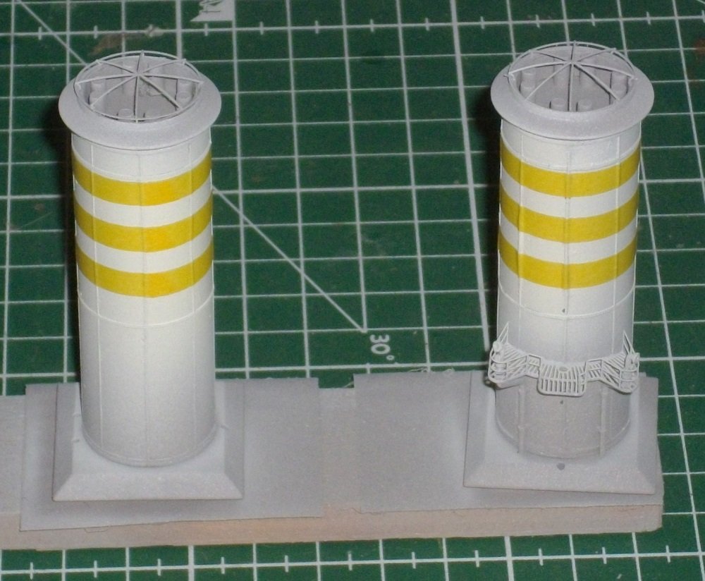
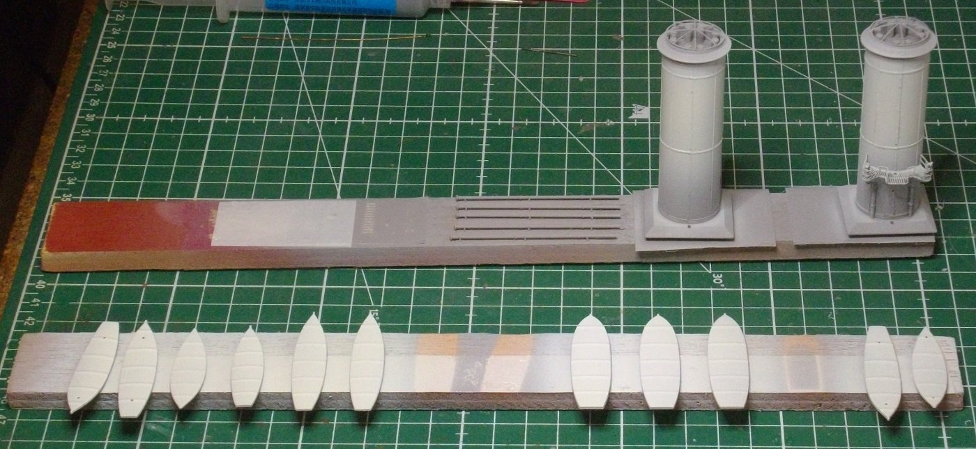
I grounded the prepared pieces with Vallejo grey. Then I airbrushed the funnels and decks covers with Vallejo 71.279 Insigna White. The hulls of the boats were airbrushed Vallejo 71.001 White. Finaly the decks and covers were joined with their respective hulls and some details added. Untill next update, enjoy modeling.
- 146 replies
-
- 6
-
-
- Mikasa
- Merit International
- (and 1 more)
-
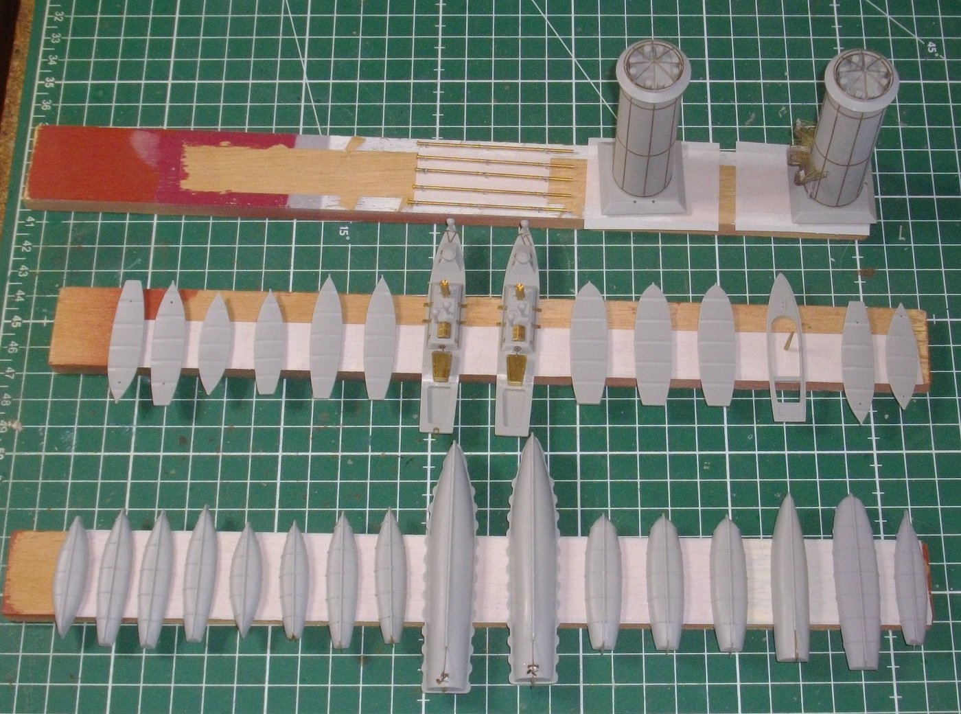
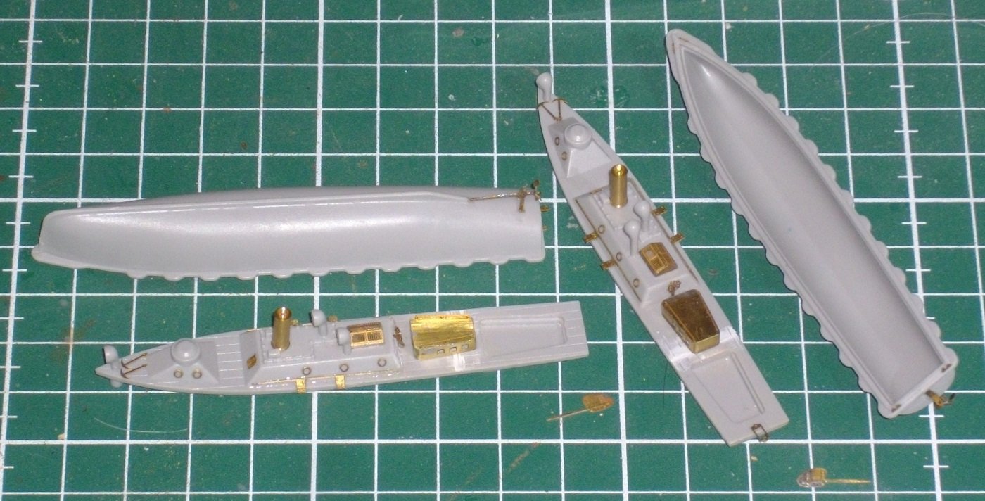
I attached the photo-etch parts to the other boats and soldered the brackets (Pontos 526) to the 5 exteral steampipes of the smokestacks (Pontos Brass 22) and I bent the 4 stairs. Sloops and smokestacks are now ready to be painted. They are attached with double sided tape to some battens which facilitates airbrushing. Kind regards, Herby
- 146 replies
-
- 5
-
-
- Mikasa
- Merit International
- (and 1 more)
-
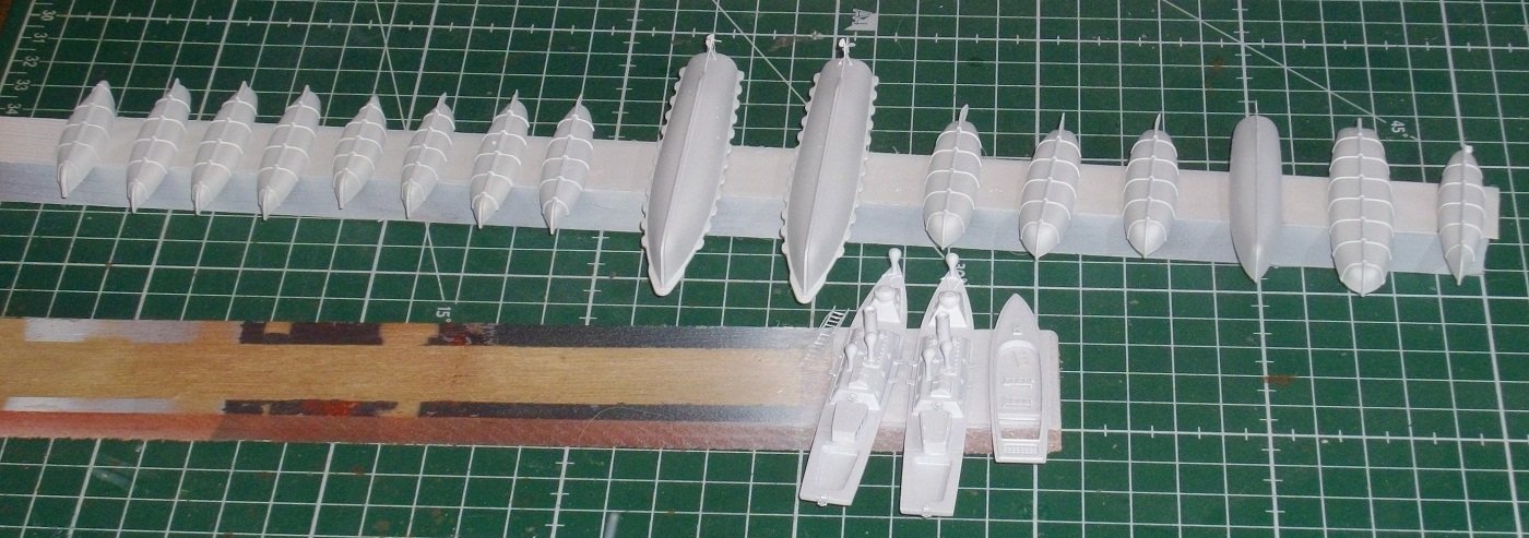
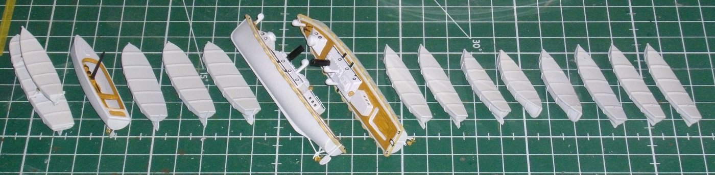
I prepared the steamlounches, collecting and cleaning up the Merit parts, and removing the details to be replaced by Pontos parts. The deck housings were soldered, and all parts were CA-ed to the hulls. Kind regards, Herby
- 146 replies
-
- 6
-
-
- Mikasa
- Merit International
- (and 1 more)
-
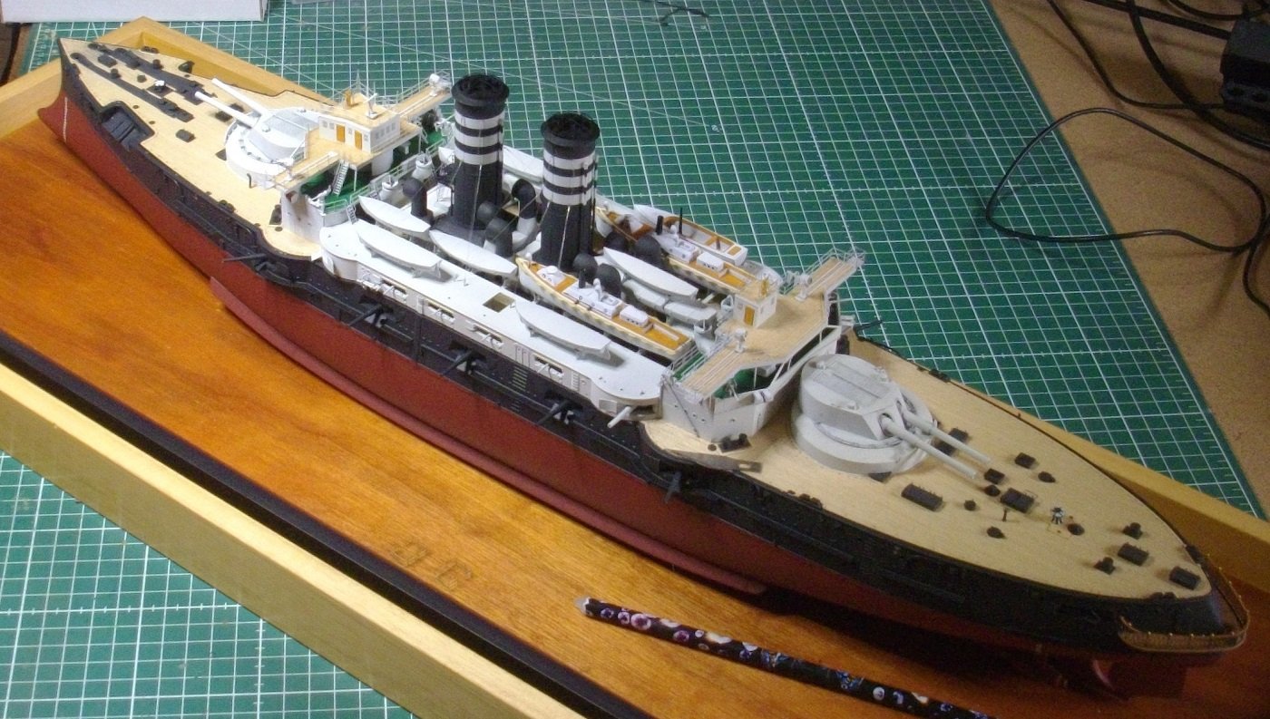
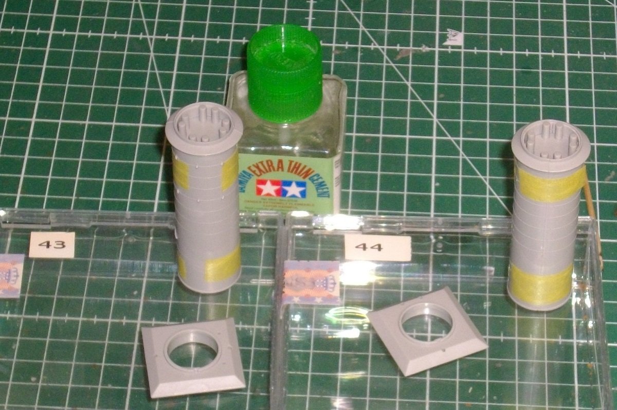
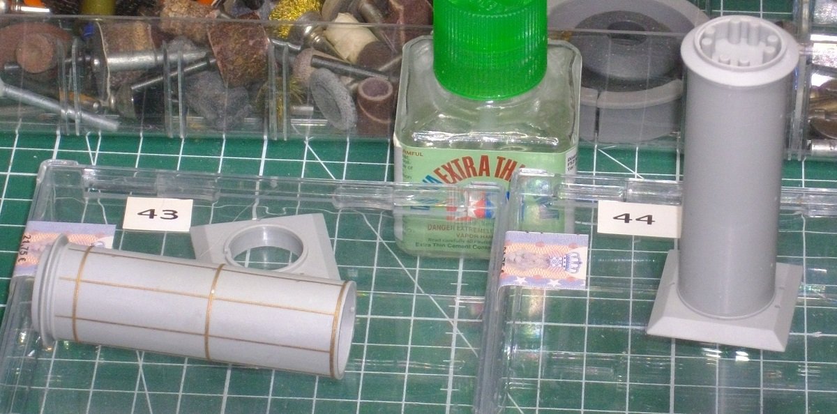
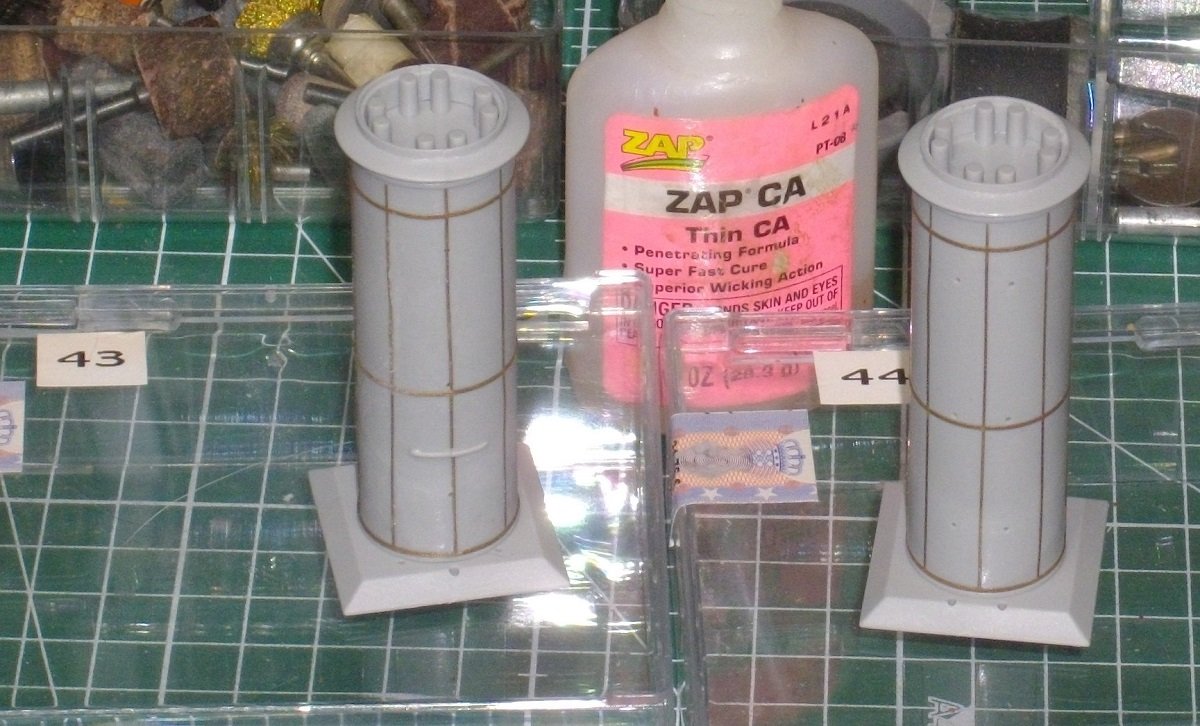
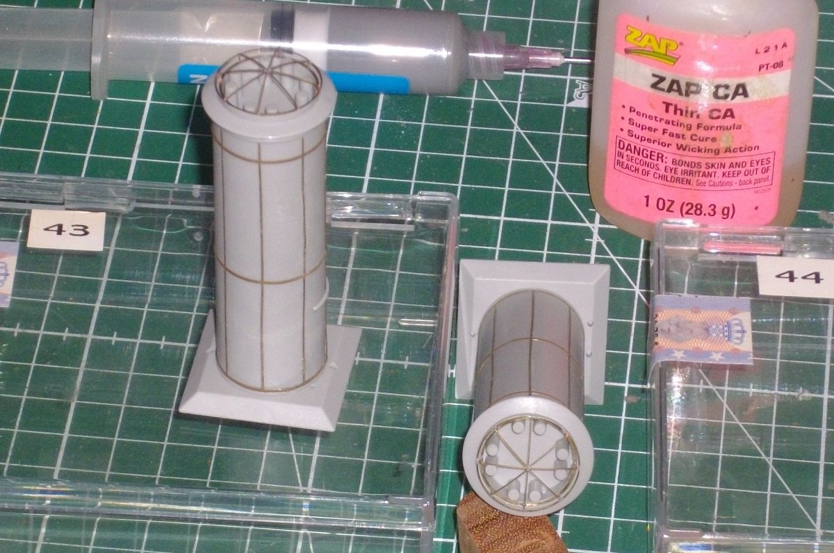
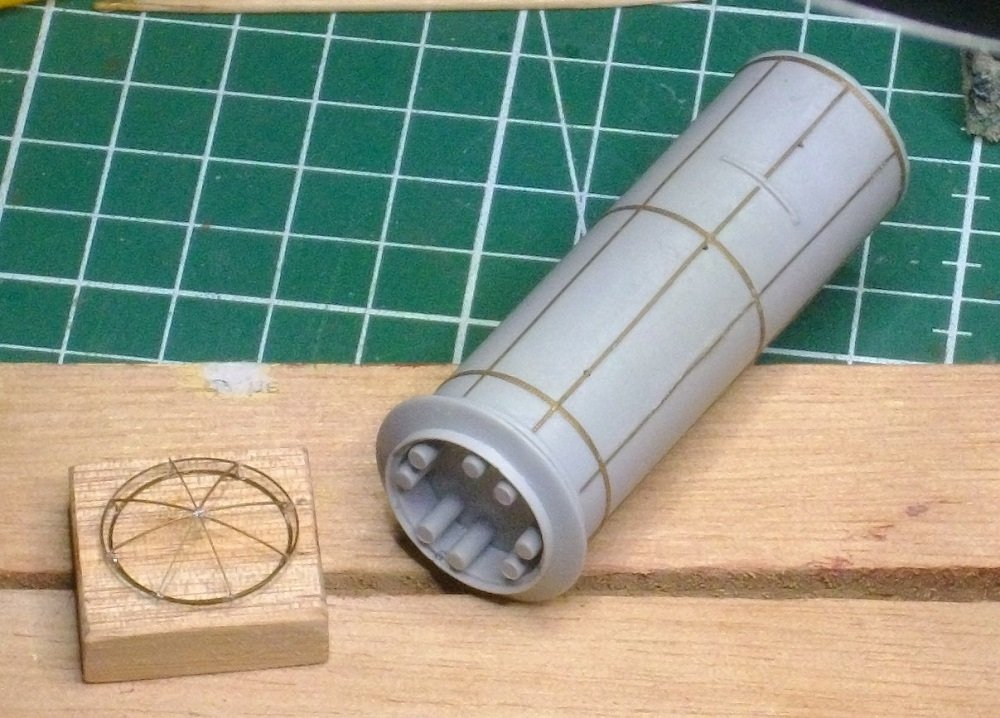
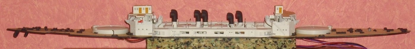
Sorry for the late reply, but thank you very much Alan ( @king derelict) for your kind words, and the other followers for the thumbs-up? Life got in the way of other plans 😁 Merit steps 43 and 44 , I assembled an cleaned the plastic parts and glued them with extra thin cement. Rivets applied to the back smokestack with pink Zap. Rivets applied to the fore smokestack. Well prerolled, the gluing goes much smoother. Then I soldered the Pontos parts for the funnel caps and clued them to the funnels with pink zap. and the funnels are glued to their bases. Next I soldered the Pontos parts for the platform. The railing demanded some accurate bending. and glued it to the fore smokestack with pink Zap. Next step is gluing the curvy pipes under the platform. and the resin steampipes on top of that. Painting will be done after preparing some more parts. Goodbuy for now.
- 146 replies
-
- 6
-
-
- Mikasa
- Merit International
- (and 1 more)
-
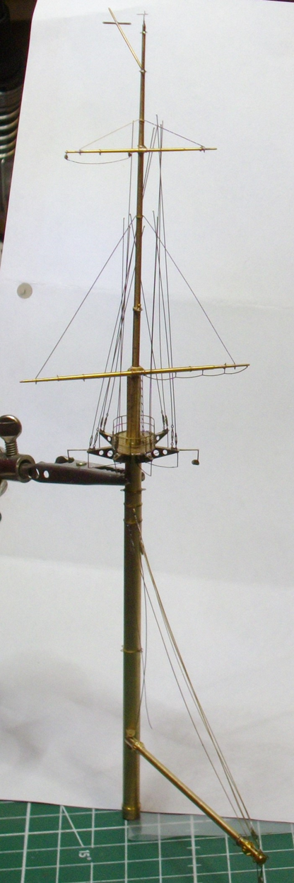
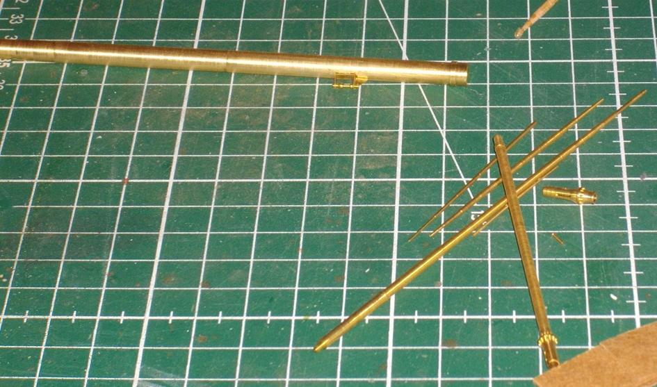
Hi Jeff, Thank you for the kind words. I test-fitted the bottom part of the mast in the holes in the deck before mast assembly. After enlarging theze holes just slightly, that's a perfect fit. For keeping the masts perfectly upright, I count on copper wire and micro-brass-tubing. This should allow for micro-ajusting of the stays. I just hope it works out as planned. Kind regards, Herby
- 146 replies
-
- 1
-
-
- Mikasa
- Merit International
- (and 1 more)
-
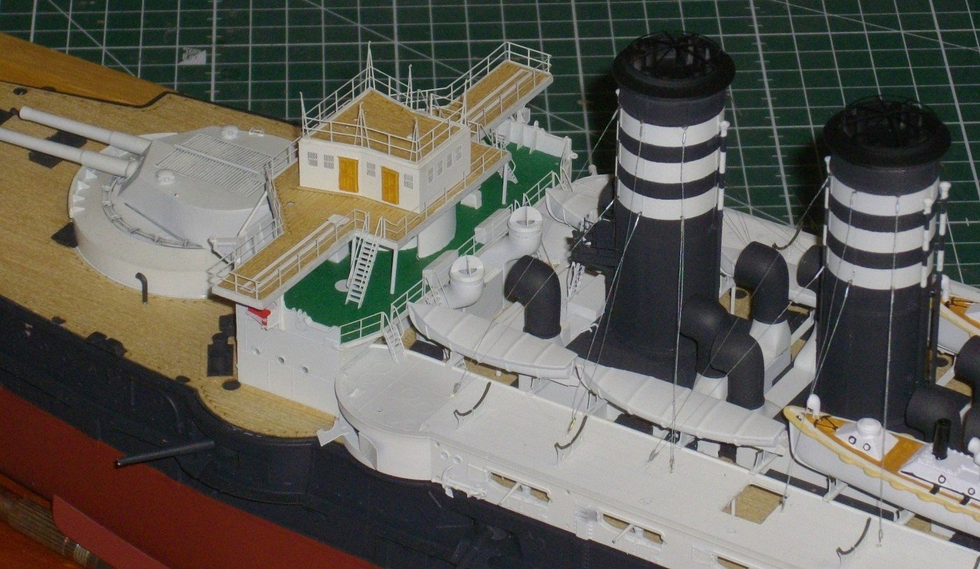
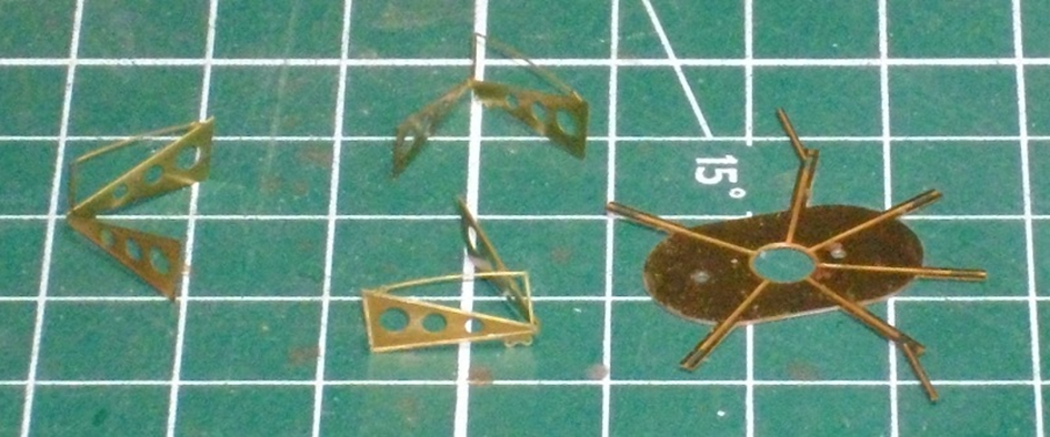
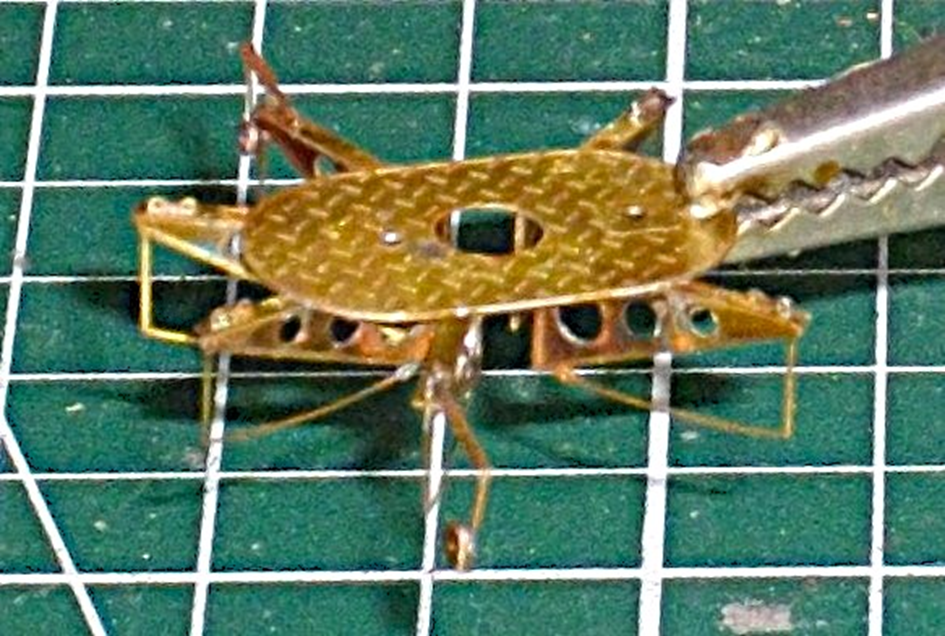
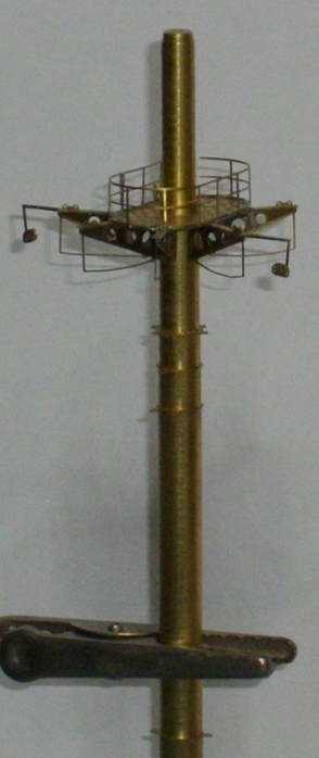
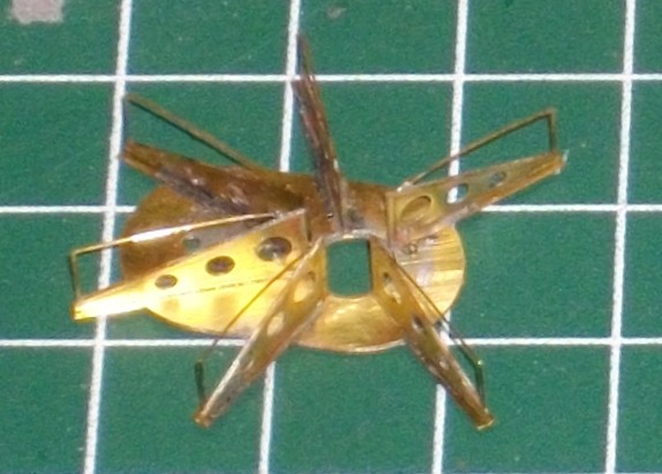
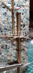
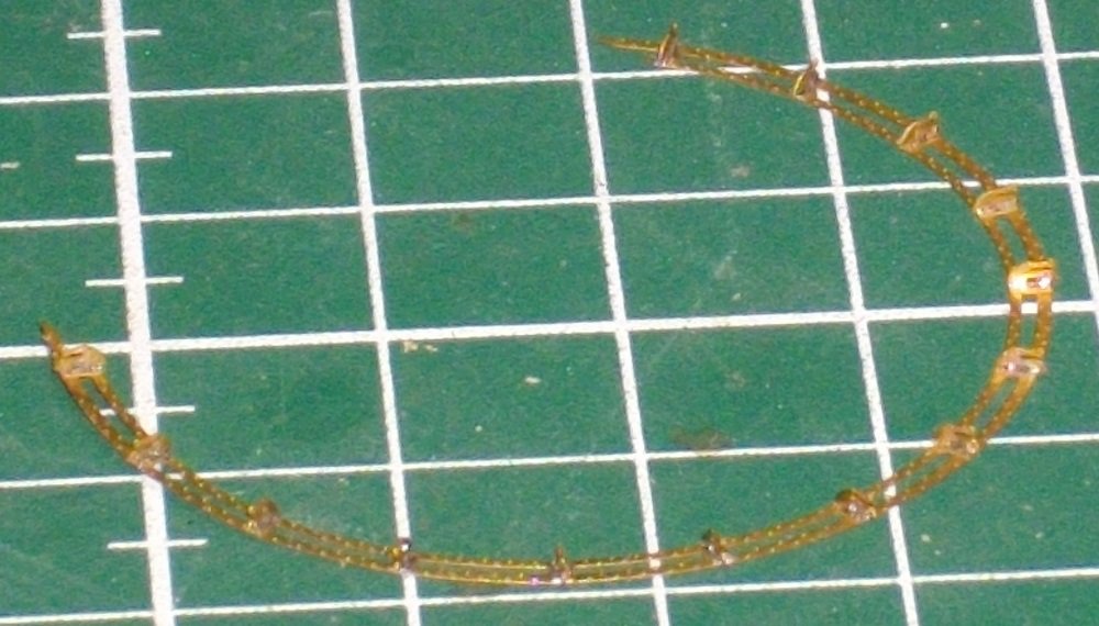
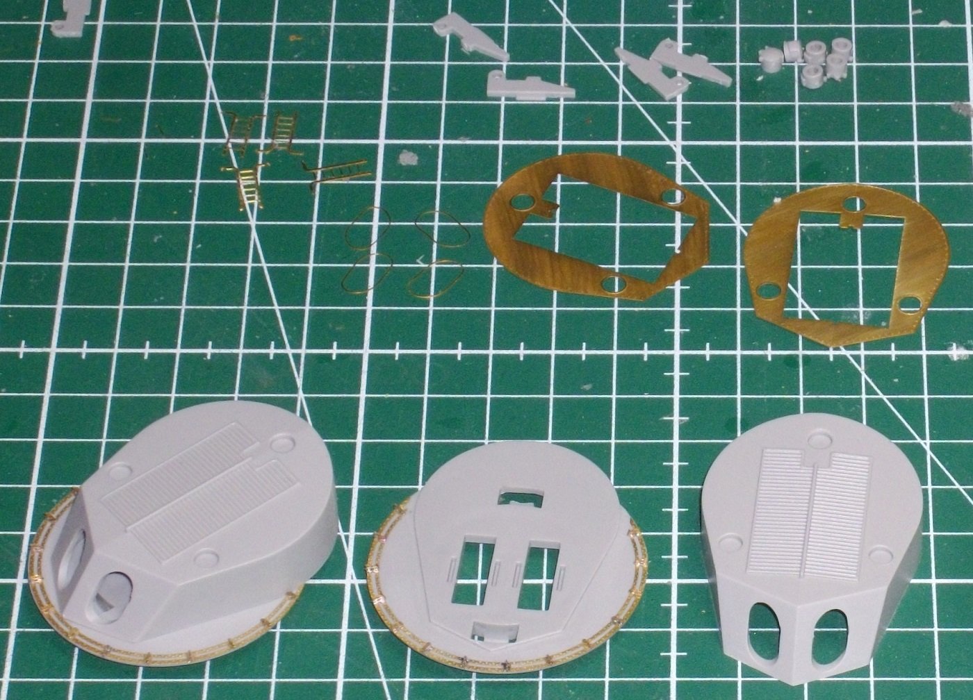
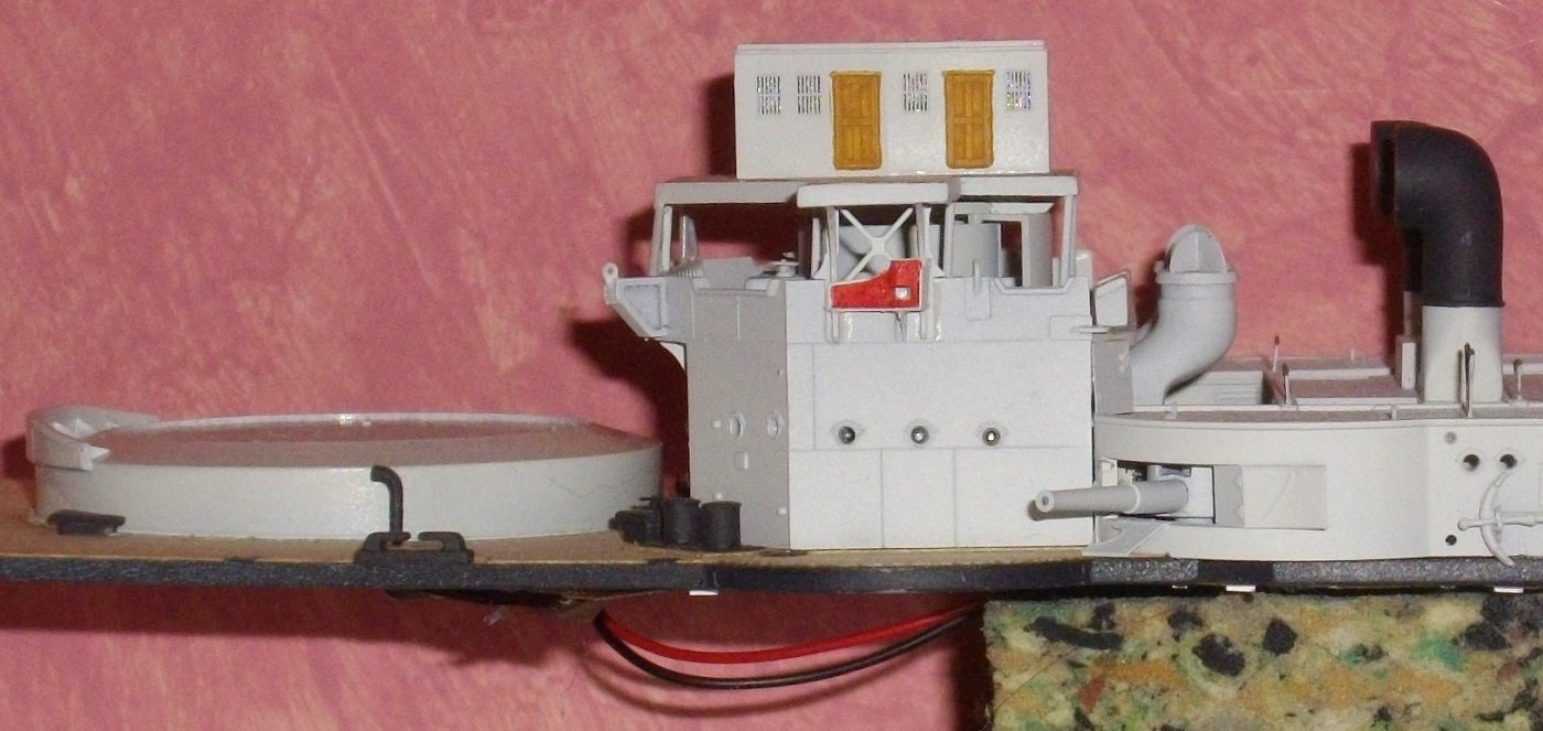
Neither Merit's nor Pontos' manual show the cylindrical platform placed halfway up the mast. Merit does supply the parts for it. A bit late, but I'm going to try to fix these platforms in the right place anyway. Platform cut in 2 and glued the largest half to the mast with pink Zap. After drying, the other piece, after removing a piece to make room for the ladders, glued with Extra thin cement to the already attached part and filled the seam with Vallejo Plastic Putty 70.401. Platform mounted in the same way on the aft mast. Ladders 374 and 376 folded and glued to the aft mast with CA glue. Main artillery airbrushed with the transparent VMS metal prep 4k and then sprayed in a light gray primer. Airbrushed both masts with VMS metal prep 4k and then sprayed them in a light gray primer. The lower part of the masts, up to and including the round platform, is airbrushed in Black Grey. Then the masts were airbrushed in Insigna white. The floors in the conical platforms painted dark green. Glued the lenses in the searchlights after the inside was painted silver. 8 47mm guns (Merit K8) Insigna painted white. Cannons and searchlights glued to the platforms of the masts. Parden me for the poor English as I note down a record of the work I do, and for this time, I used an app to translate. Enjoy modelling, next update will show the funnels.
- 146 replies
-
- 7
-
-

-
- Mikasa
- Merit International
- (and 1 more)
-
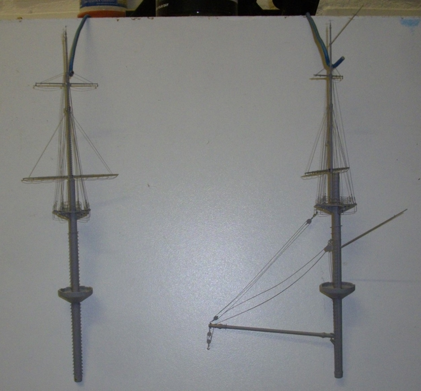
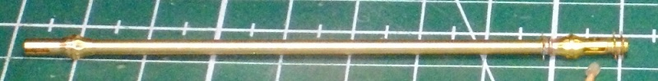
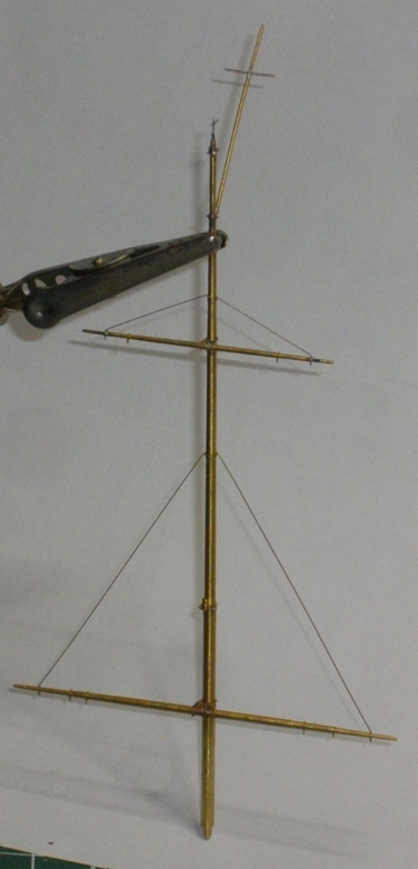
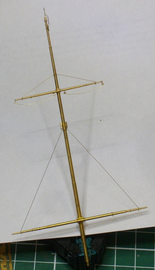
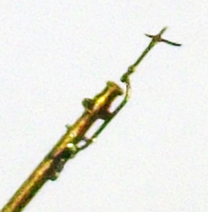
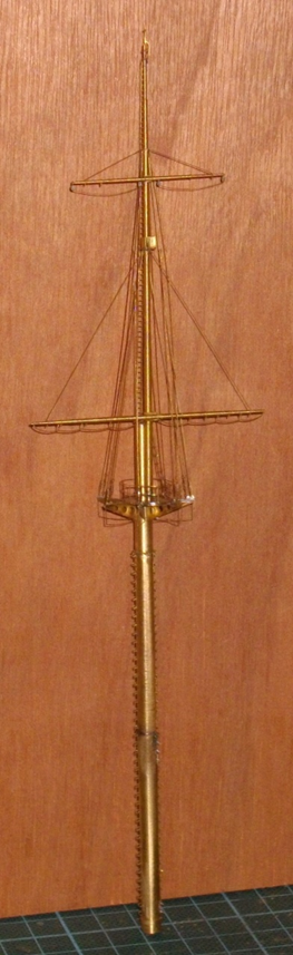
Main mast (or aft mast, they are both the same height) Bracket for loading boom folded and glued to the lower mast Rings glued boom ends soldered Platform double folded and brazed Yards, topmast and flagpole assembled. Platform 323 slid over the masthead. Railing 327 rolled/bent into shape and soldered to the platform. Glued the Topmast with brackets 277 and 278 to the masthead. Ladder 328 folded at the top and glued to the mast head. The foot horses glued under the main yard. Front rigging (2 x 764, 765 and 766) placed, the bottoms soldered, Tops of the stays glued to the topmast with Slo-Zap Enjoy modeling, til next update.

- 146 replies
-
- 8
-
-
- Mikasa
- Merit International
- (and 1 more)
-
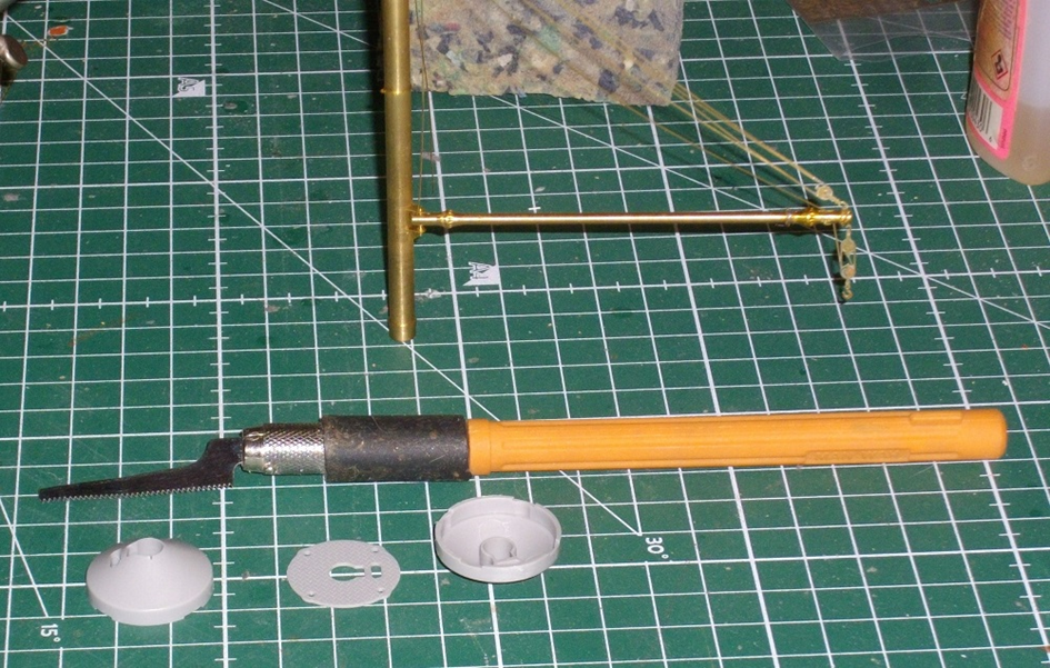
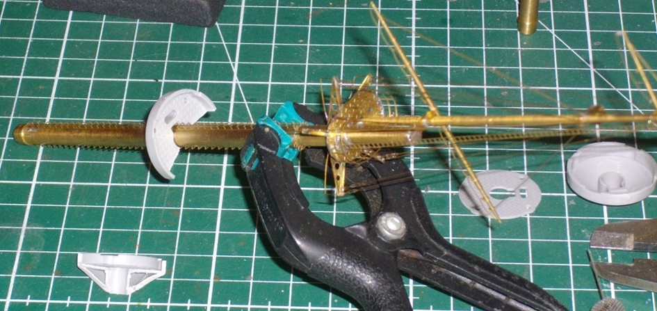
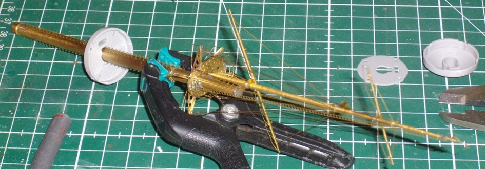
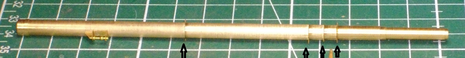
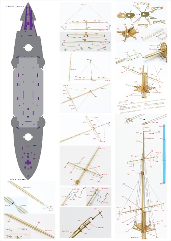
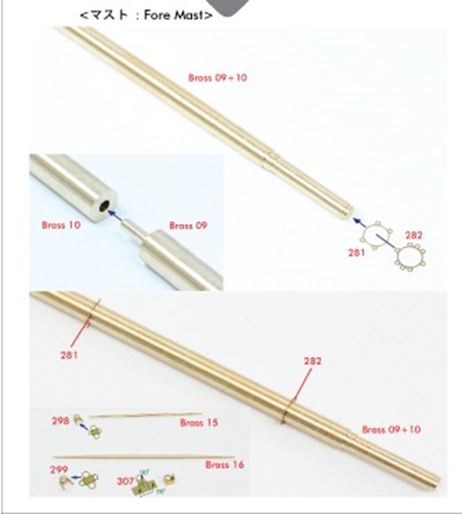
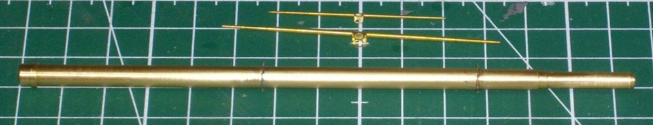
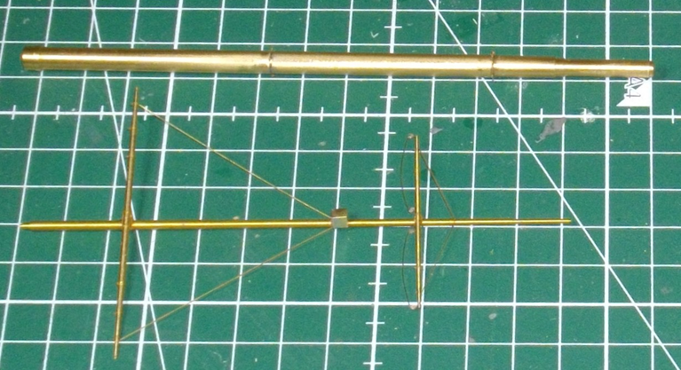
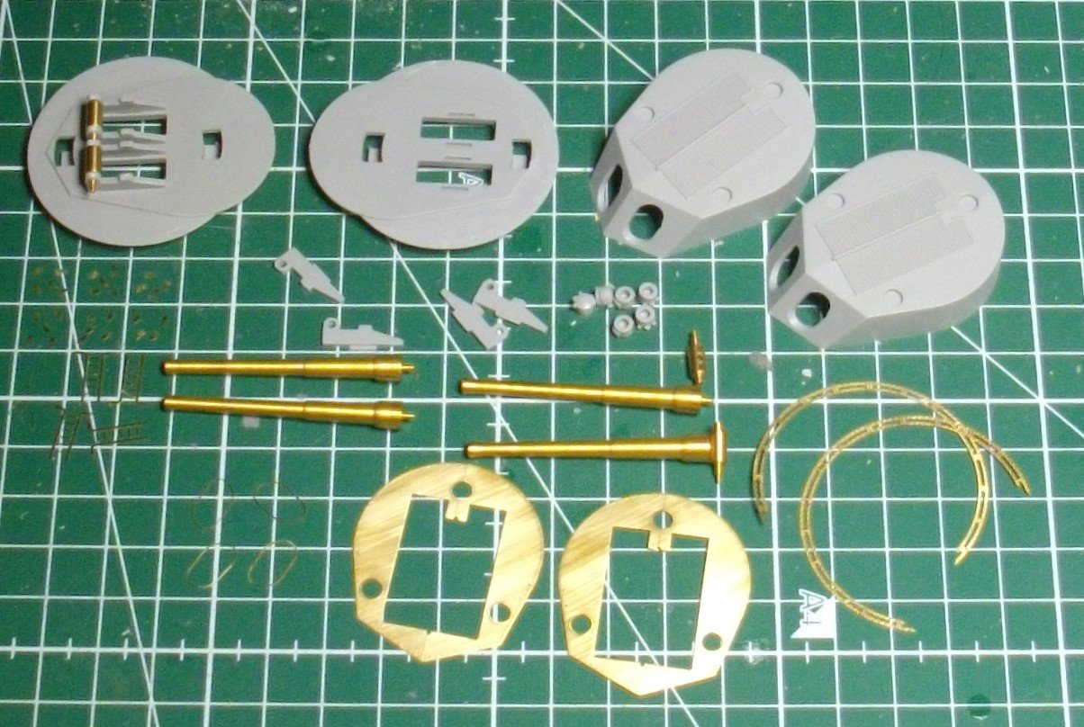
Next in the Merit instructions are the masts (steps 41-fore mast and 42- aft mast). They are entirely replaced with Pontos parts (turned brass and photo-etch. As i am painting my model in the 1902-sceme, the platforms, which are in the Merit parts will be added, albeit in a very late stage. 😱 Starting with the fore mast - The Pontos instructions: The 2 parts of the lower mast are glued together, my soldering iron does not get hot enough. so the rings 281 and 282 are glued as well. Brackets 298 and 299 are bent as per the instructions and glued in the center of the yards, Brass 15 and 16. Brackets 291 and 292 are glued to the main yard. Lifts nr 325 folded, slid over the yardarms, slid the assembly over the fore topmast and soldered the bracket of the main yard to the topmast. Mini crow's nest nr 307 folded, soldered and slid over the fore topmast. Brackets 293 slid over the small yard and glued the foot horses 276 to it. Lifts 326 folded and attached to the topmast together with the small yard. Bracket 294 slid over the topmast. Bracket 306, ring 288 and top light (Brass 32B) soldered to the end of the topmast. Brackets 279+305 soldered to the side of the top of the topmast. Supports 271, 272, 273 and 274 soldered to the underside of platform 312. Platform 312 slid over the masthead. Brackets 314 and 313 slid over the masthead. The topmast slid through the brackets 313 and 314 and into the hole in platform 312. Brackets and topmast soldered. Fence 327 rolled/bent into shape and soldered to the platform. Ladder 328 folded at the top and soldered against the mast head. Front rigging (2 x 761, 762 and 763) placed, the bottoms soldered, the tops glued with SloZap). Ladder 324 glued to the fore topmast. The horses glued under the fore yard. Ladders 375 and 376 folded and glued to the foremast with CA glue. Next update will be the assembly of the main mast. Kind regards.
- 146 replies
-
- 9
-
-
-
- Mikasa
- Merit International
- (and 1 more)
-
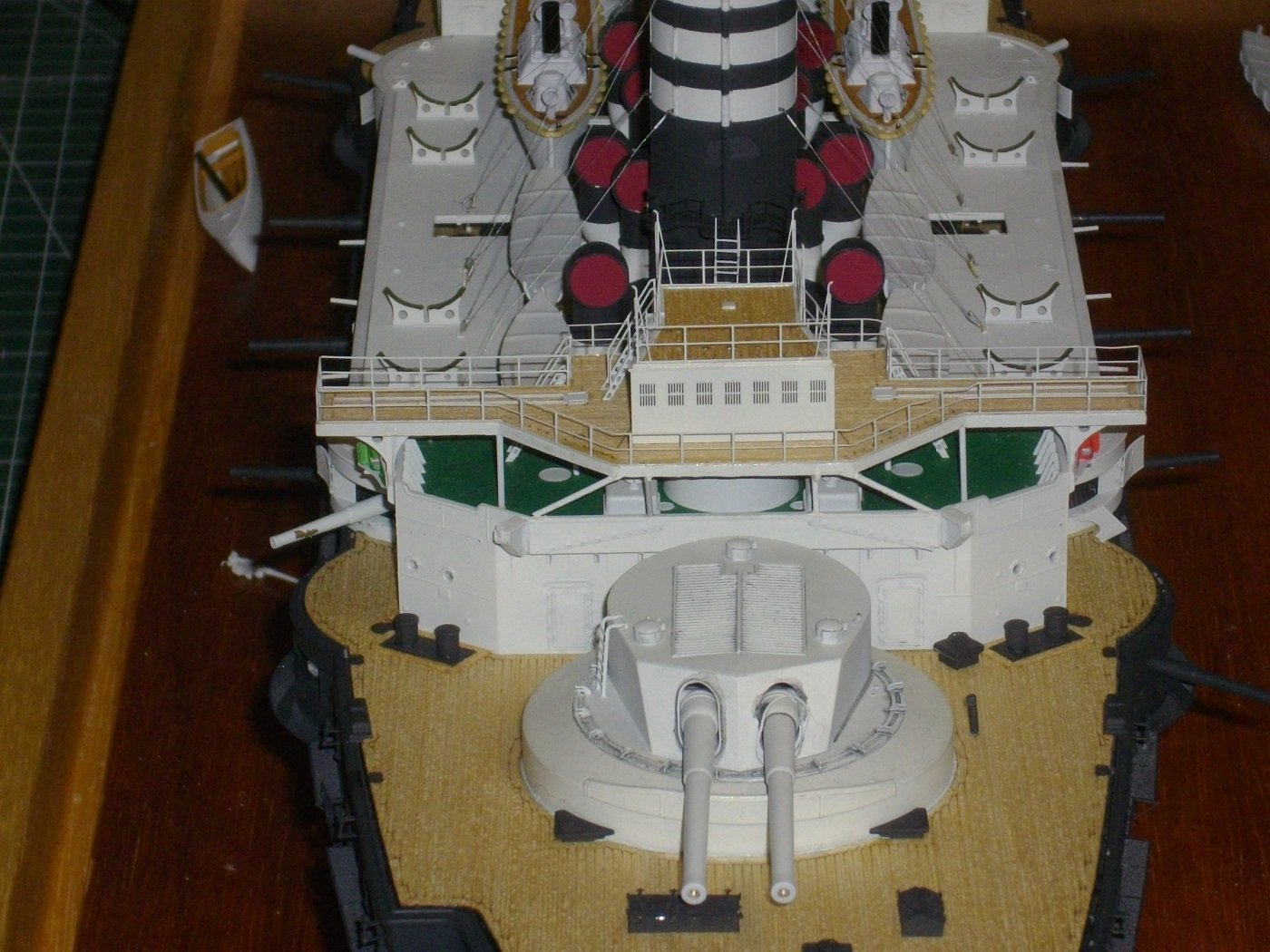
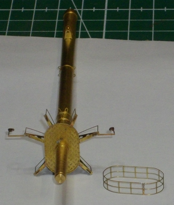
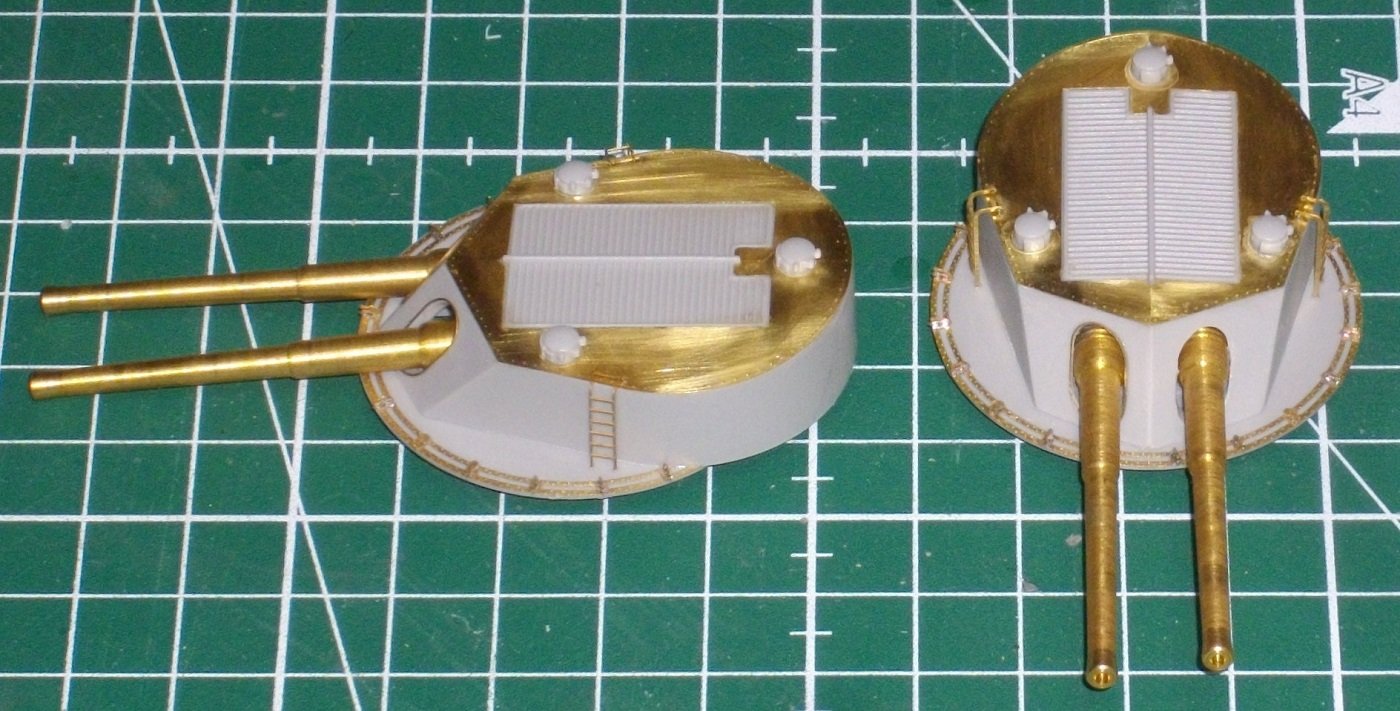
Thank you for the lovely comment Jeff, makes me want to continu and publish a long awaited and overdue update. Due to multiple personal events in 2024 I was a bit discouraged to work on al this fiddly stuff, so I fulfilled a childhood dream for some 1/16 panzers, that I documented on the dutch modelforum. Tiger I, Elefant en Königstiger 1/16 RC by Herby63 | ModelbouwForum.nl Tiger I, Elefant en Königstiger 1/16 RC by Herby63 - deel 2 - Elefant | ModelbouwForum.nl Tiger I, Elefant en Königstiger 1/16 RC by Herby63 - deel 3 - Königstiger | ModelbouwForum.nl Now that these are finished, I am slowly taking up this build. So lets see what has been done in the past 5 months. I passed on to the main armament (step 40 in the Merit manual, to be completed with quite some pontos-parts). Here you see the parts to be assembled: I soldered the barrels to the trunions, and the tiny hooks to the rings. 1 square = 1 cm Then I glued the brass rings to the turret bases with pink Zap. I soldered the supports for the ladders that go to the sides of the turrets to the brass top plates and glued the top plates to the turret tops with pink Zap. The barrels are attached to the turret bases and the 3 small cupolas were glued to each turret top with thin cement. The fine brass linings of the turret openings for the barrels are glued in place with some pink Zap and the turret tops are glued with thin cement to the bases. Finaly the ladders are attached with a little pink Zap. After applying a basecoat, they have been airbrushed Insigna White. Until next time, enjoy medelling.


- 146 replies
-
- 4
-
-
- Mikasa
- Merit International
- (and 1 more)
-
Thx Jeff, Indeed it looks lovely in the dark, but is hard to catch in a picture.
- 146 replies
-
- 2
-
-
- Mikasa
- Merit International
- (and 1 more)
-
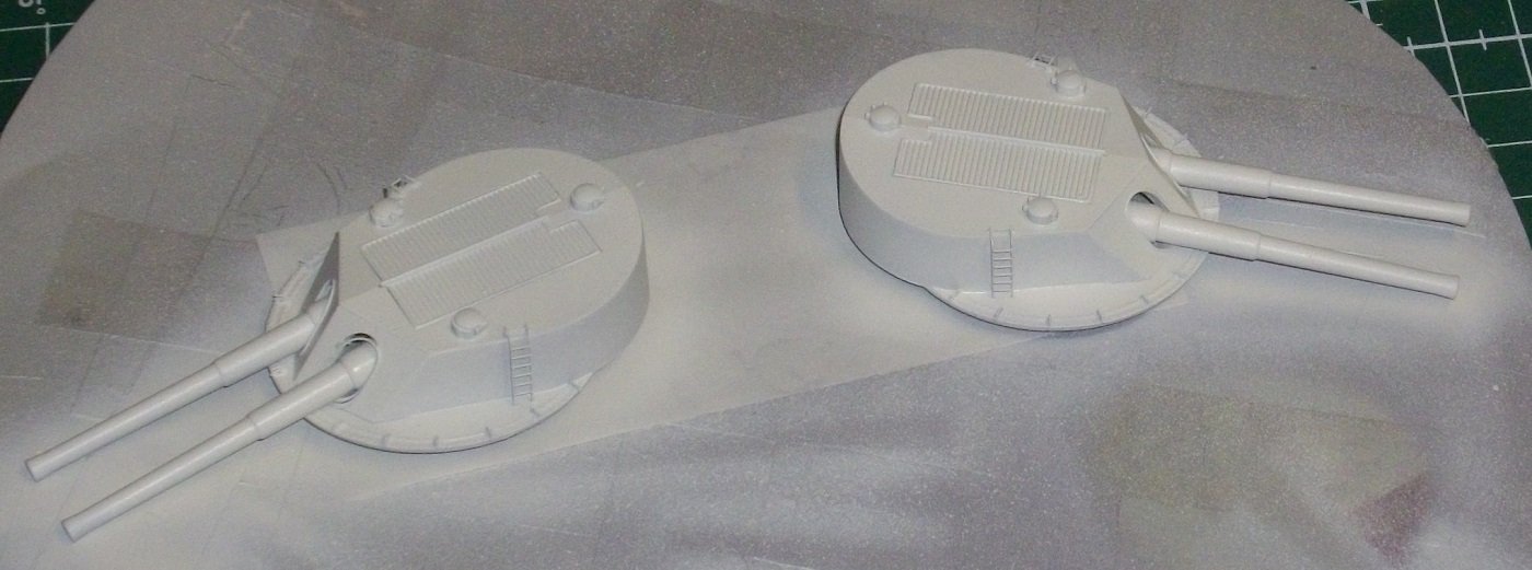
Hello dear followers, As the spraybooth is installed for an other project, I airbrushed the main guns with VMS Metal Prep 4K and grey primer and gave them their final coat of Insigna white. here is the result: Until next update, enjoy modelling.
- 146 replies
-
- 6
-
-
- Mikasa
- Merit International
- (and 1 more)
-
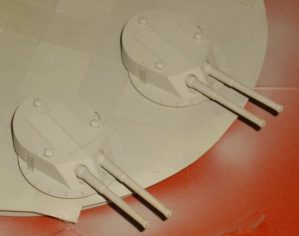
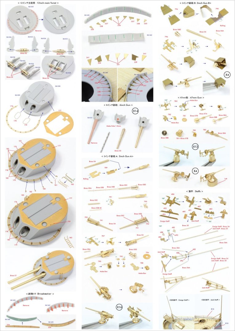
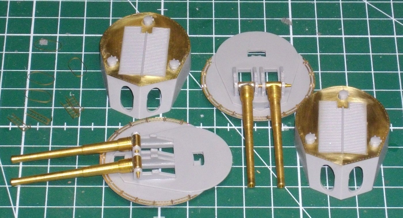
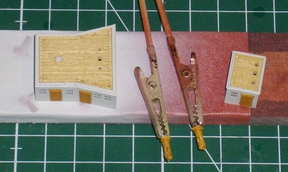
Hello dear followers, Today I show the main guns being made. The Merit parts are upgraded or, in some cases, replaced by Pontos-parts. The (Pontos)manual: The parts: The brackets have been soldered to the rings. The rings are glued to the turret bases with pink Zap (thin CA-glue. Barrels solderd to the trunnions, trunnions inserted in the cheecks and the cheecks glued with Tamiya extra thin cement to the bases. The brass rooftops were glued on with pink Zap. And finaly, the turret tops were glued on the bases. Ready for painting. Following the steps in the Merit manual, the next update will be the masts. Until next update, enjoy modelling.

- 146 replies
-
- 6
-
-
-
- Mikasa
- Merit International
- (and 1 more)
-
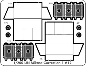
Hi Jölle, Pontos isued a #12 correction fret to rectify this, but my attempts to get one from them had no success. Very nice work tho.👍
- 196 replies
-
- 3
-
-

-
- Russo-Japanese War
- Mikasa
- (and 2 more)
-
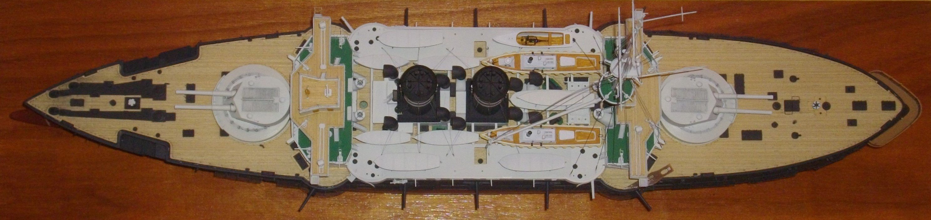
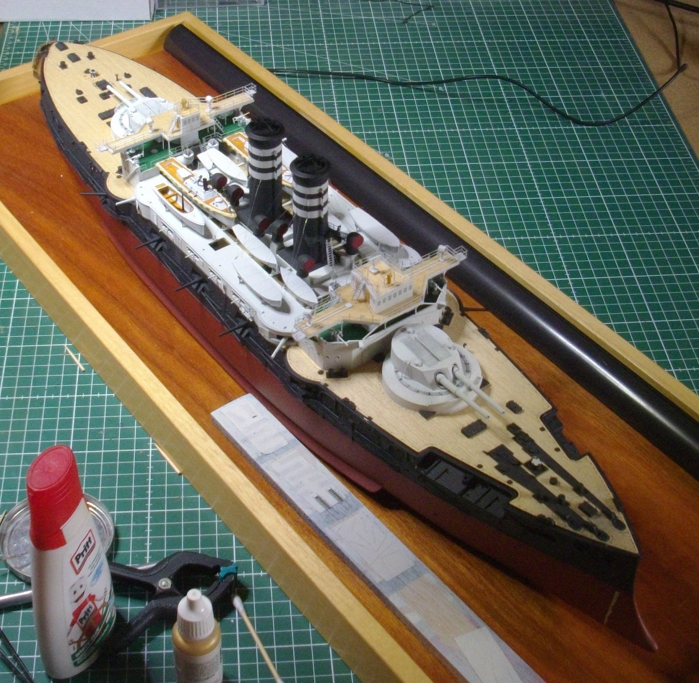
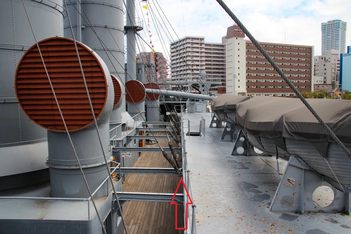
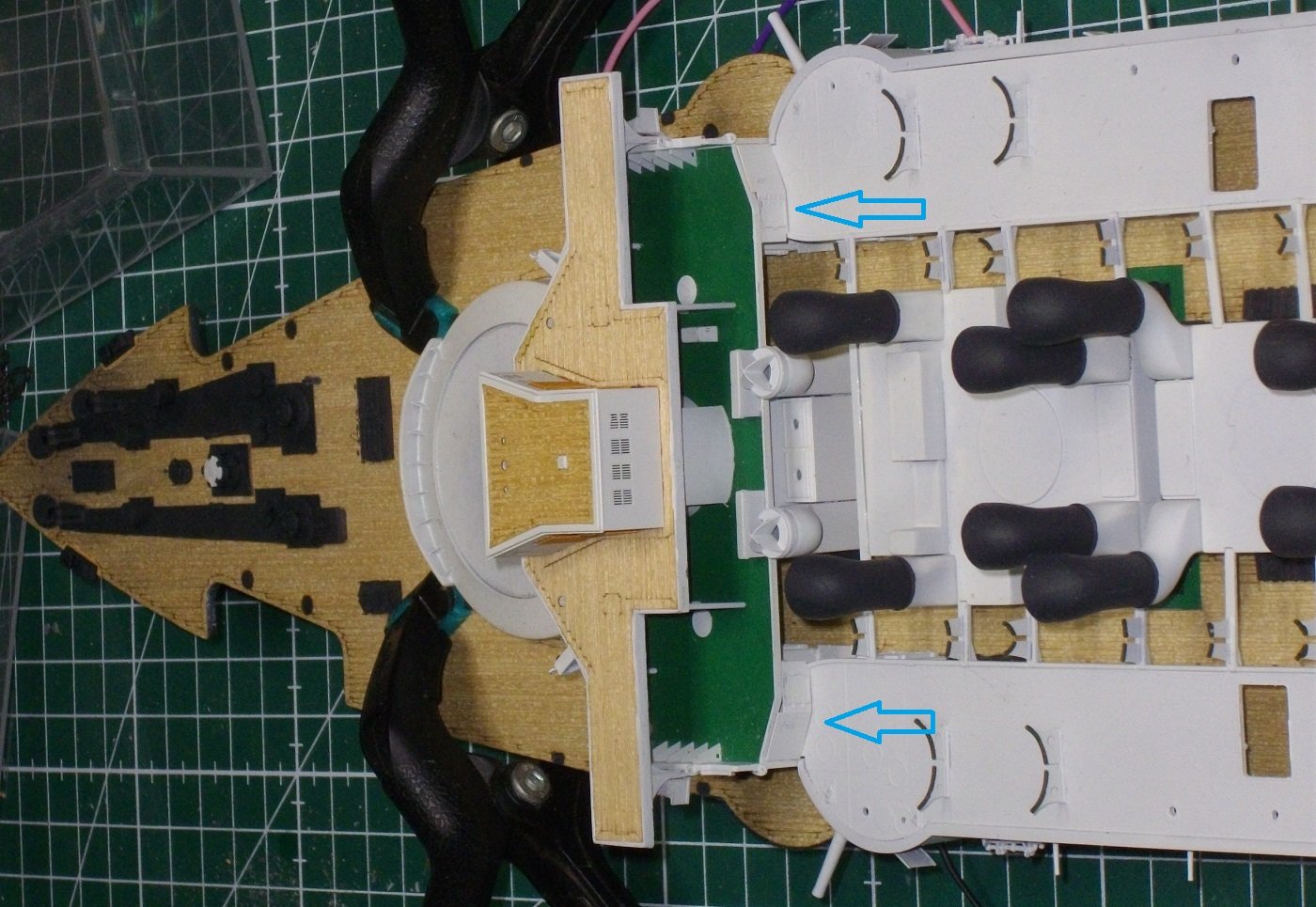
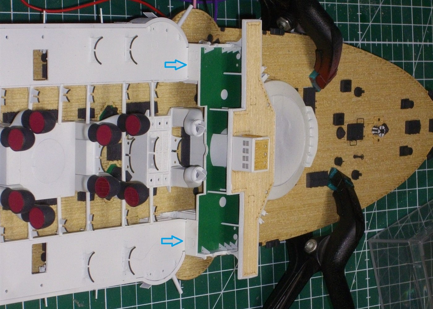
After applying a coat of gloss varnish to the rooftops, I put on the wooden decks. I painted doors and the the binnacles a wood color. The deckhouses were glued on their place with a fair amount of CA-gel and the bulkheads indicated with the blue arrows with pink Zap. Finaly I glued on the port and starboard light housings. Which gives this over all view Untill next update, enjoy modelling.
- 146 replies
-
- 5
-
-
- Mikasa
- Merit International
- (and 1 more)