
madtatt
-
Posts
115 -
Joined
-
Last visited
Recent Profile Visitors
946 profile views
.jpg.d84ec4dad1d7791e855dca06210ab6f3.thumb.jpg.f45209242e851d4409eca1a09293165b.jpg)


-
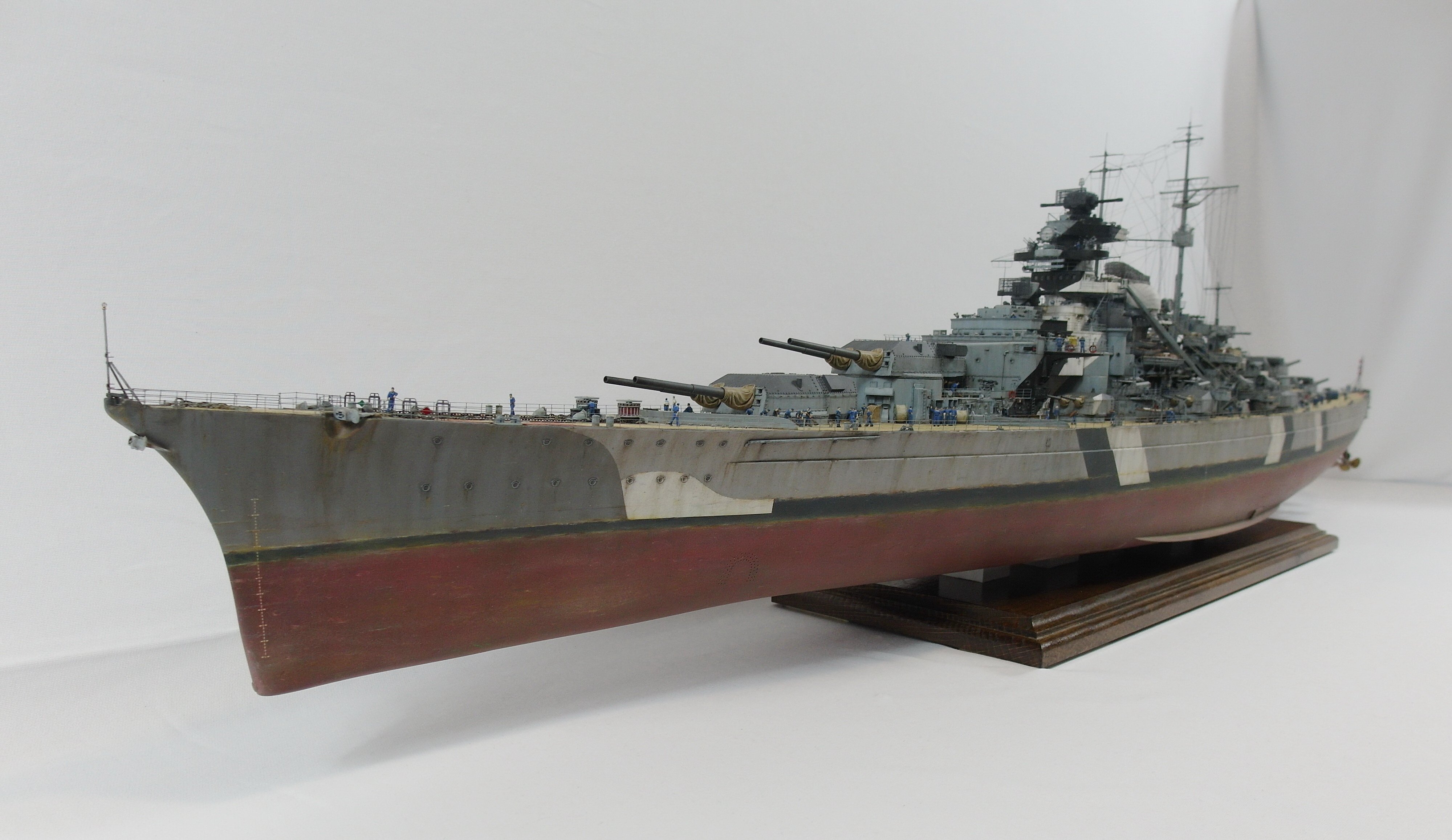
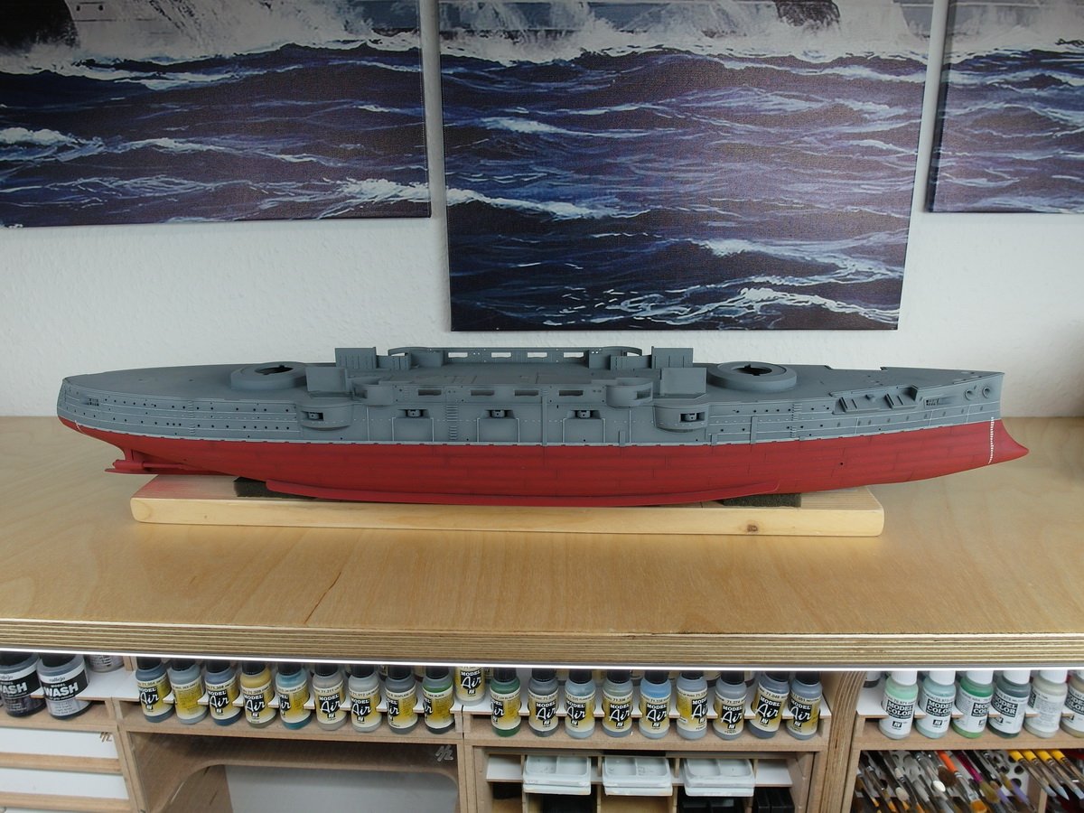
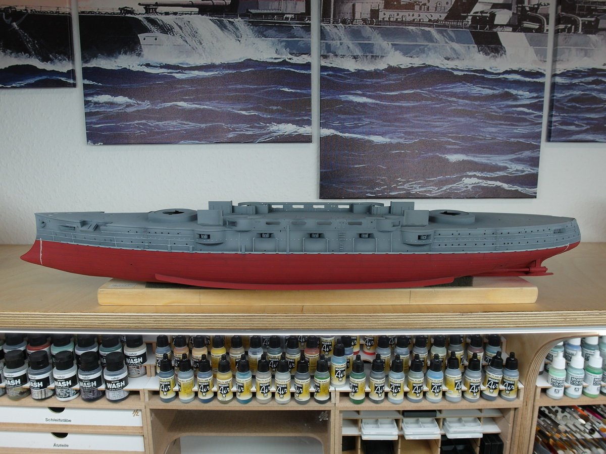
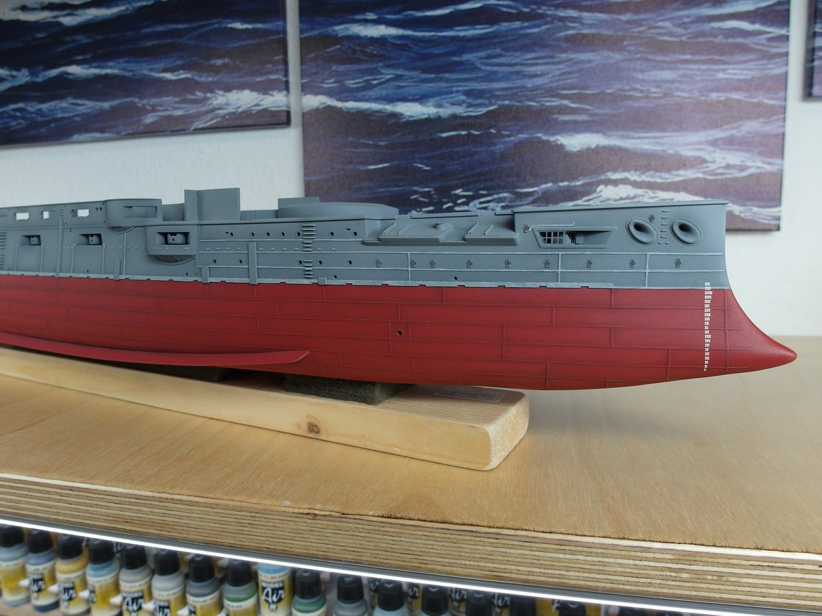
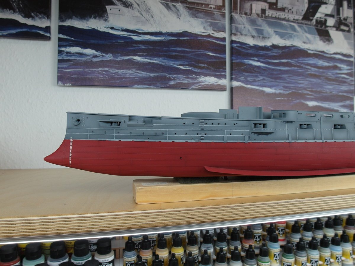
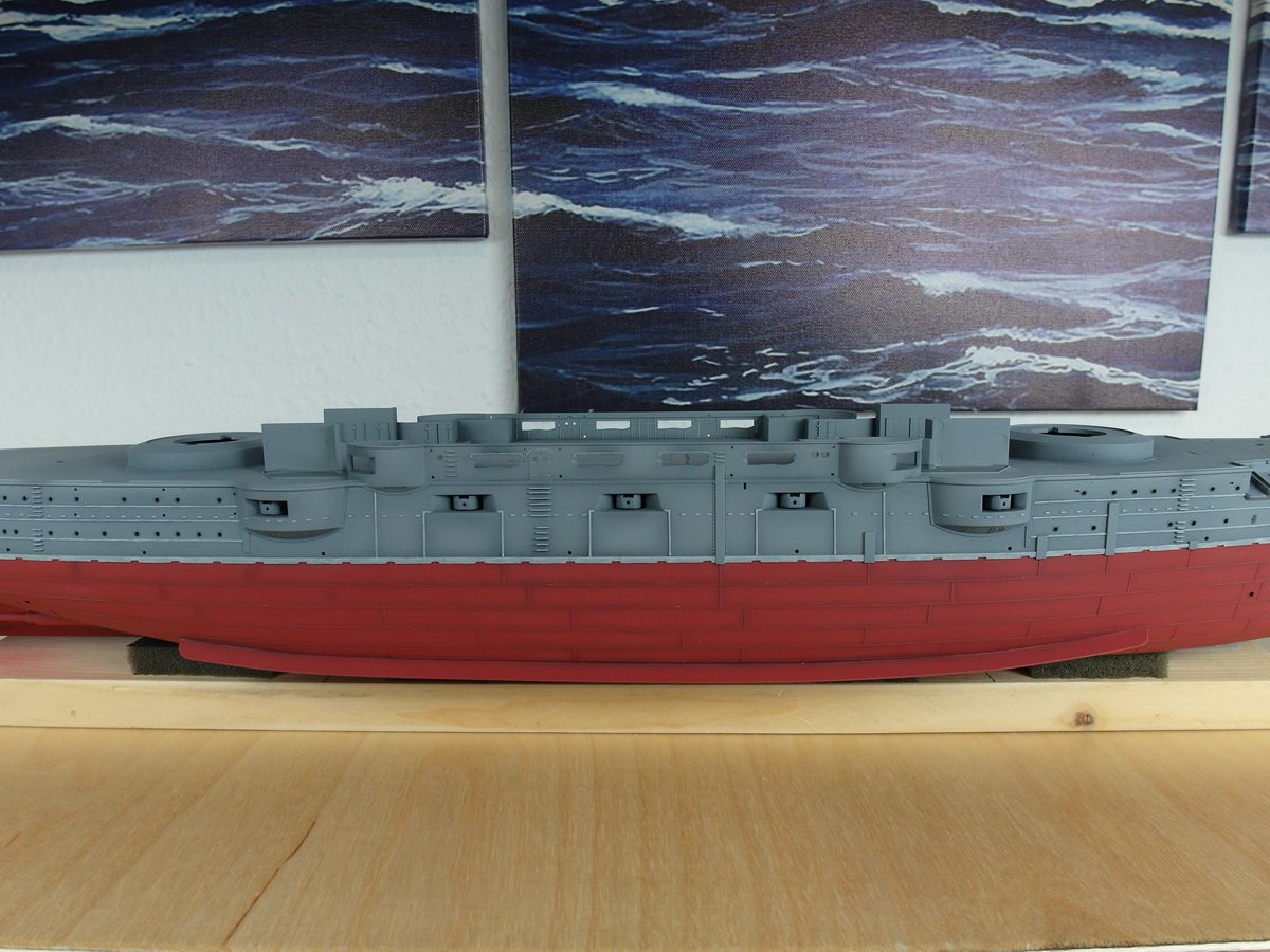
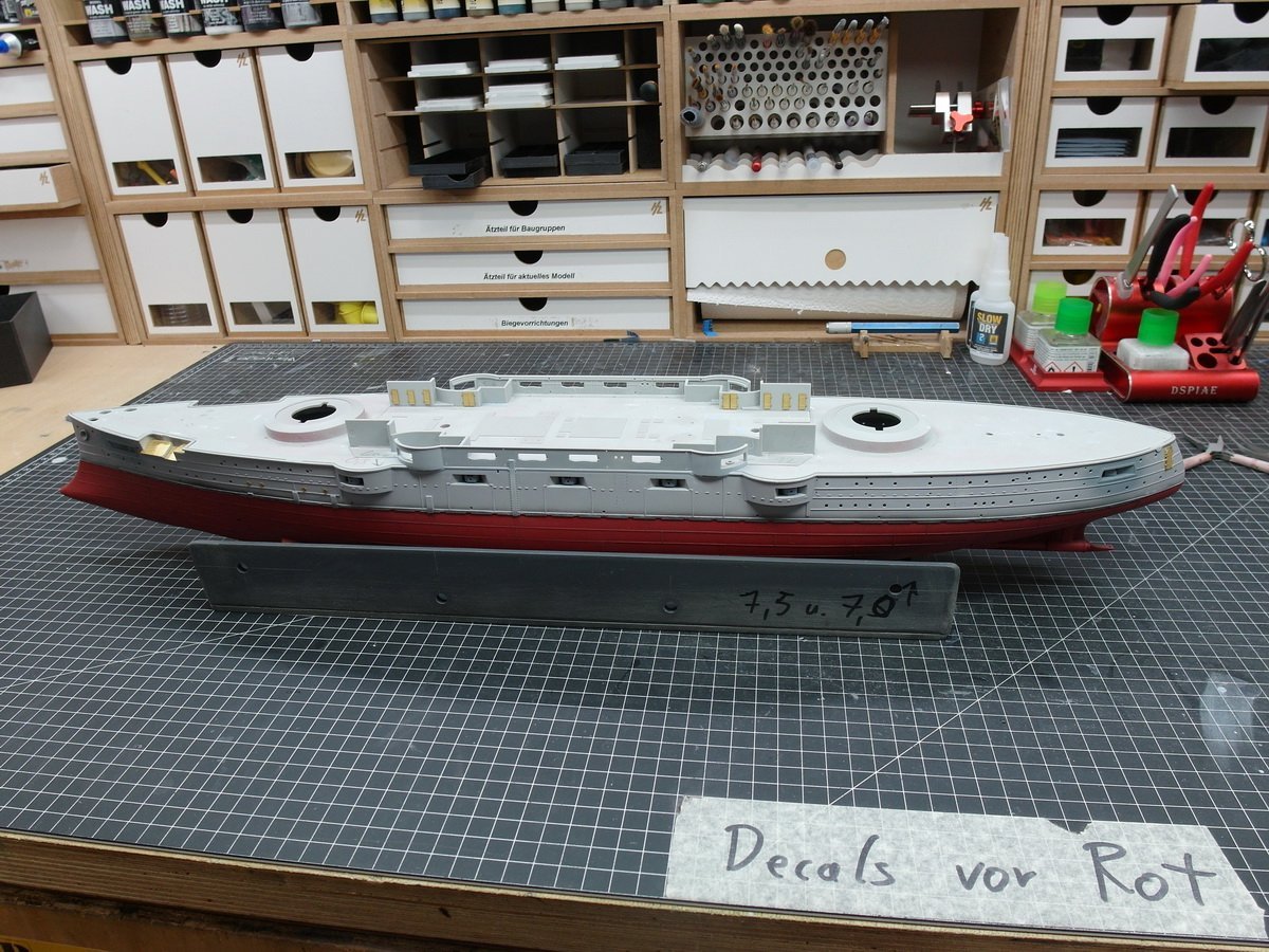
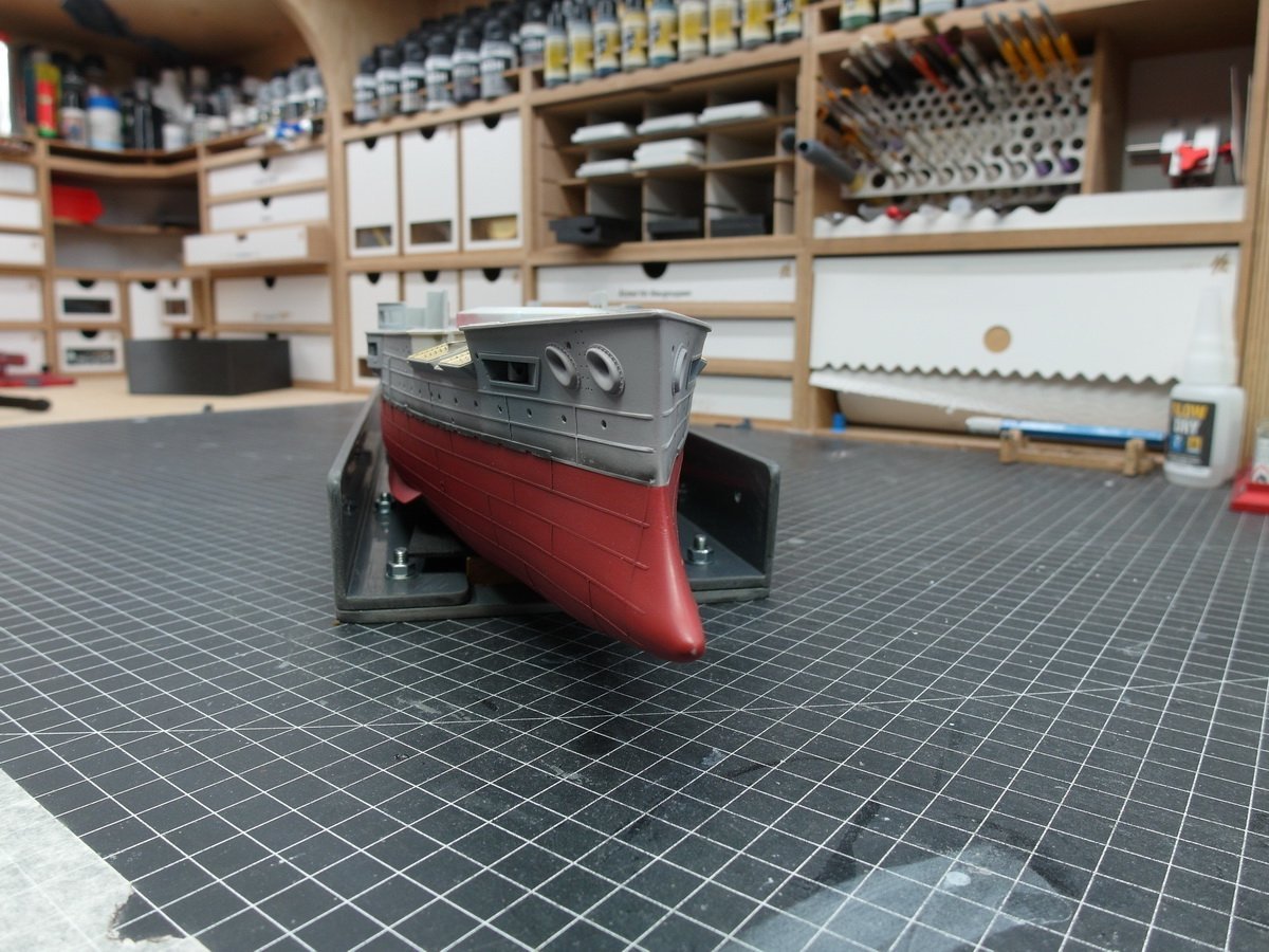
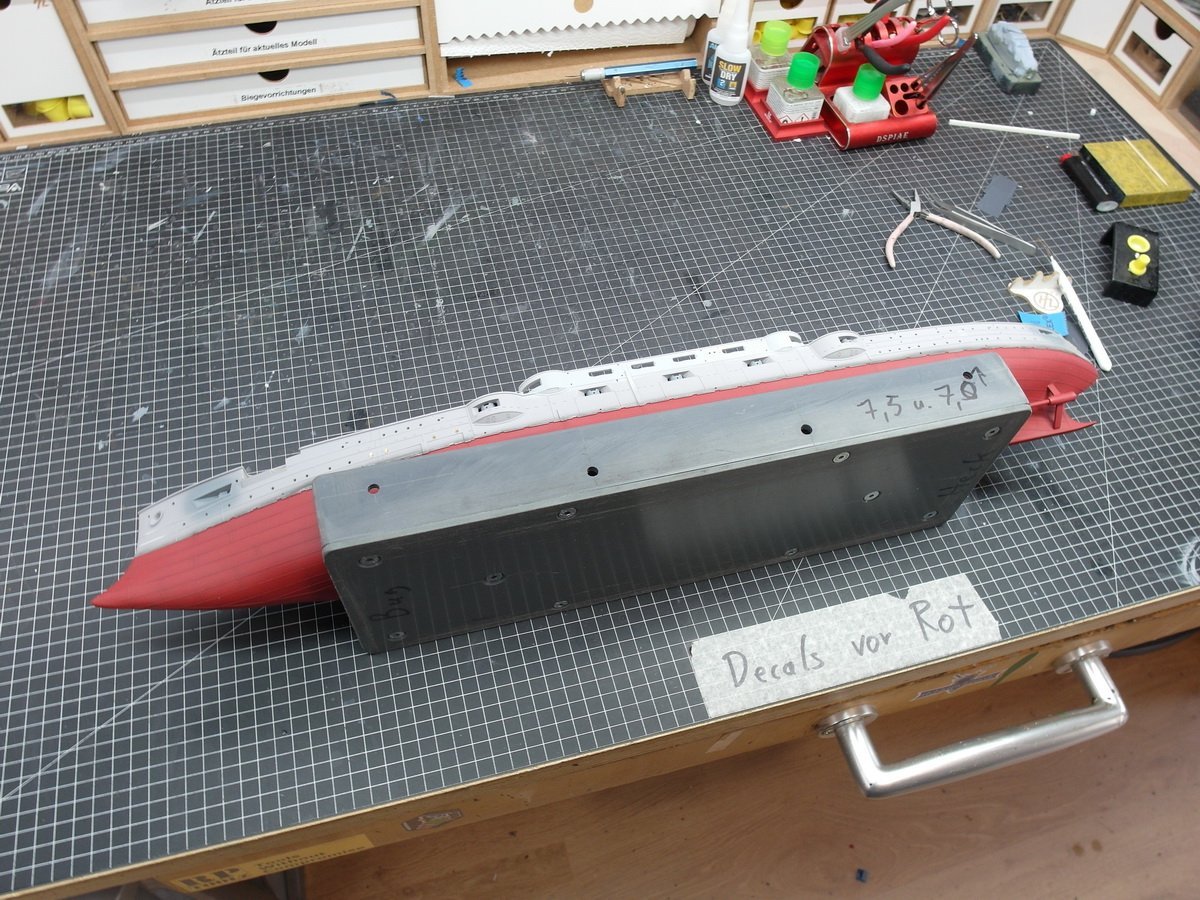
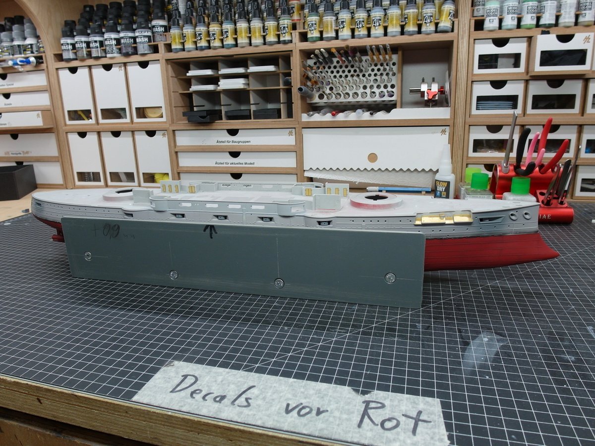
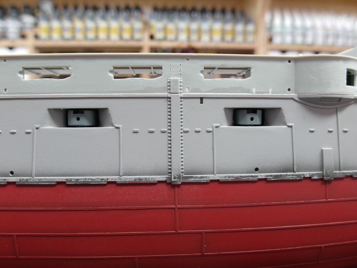
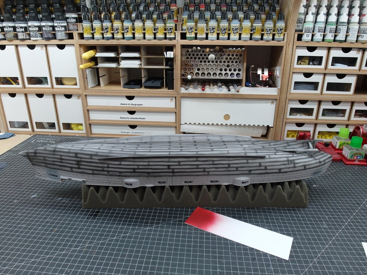
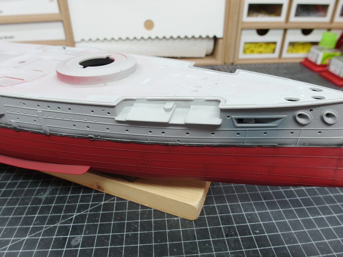
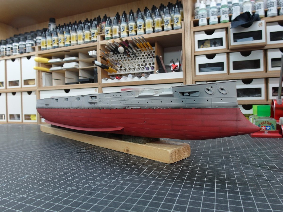
 I finished all the rough work on the fuselage and was finally able to finish painting it. After a proper preshading the whole thing now looks like this. What followed was an accentuation. Which means nothing other than that I painted fine details in a lighter gray. Which was a real fiddly job. The dry decals from Pontos are really impressive. The depth marks are razor sharp. Here too, water-soluble acrylic paints have a big advantage. Small slips can be removed immediately with water without leaving any residue. This gives a decent contrast to the preshading areas. Now i can start aging.
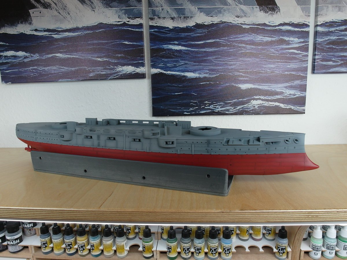
- 26 replies
-
- 3
-

-

-
- Russo-Japanese War
- Mikasa
- (and 2 more)
-
madtatt reacted to a post in a topic:
IJN Mikasa by Herby63 - Merit International with Pontos set - 1/200 - PLASTIC
-
madtatt reacted to a post in a topic:
IJN Mikasa by Herby63 - Merit International with Pontos set - 1/200 - PLASTIC
-
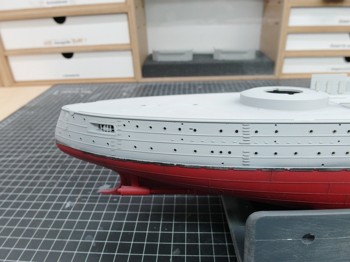
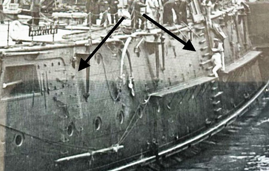
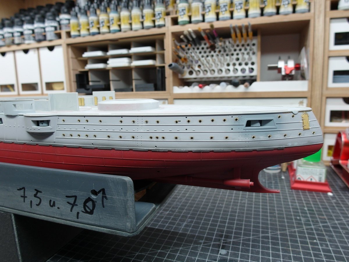
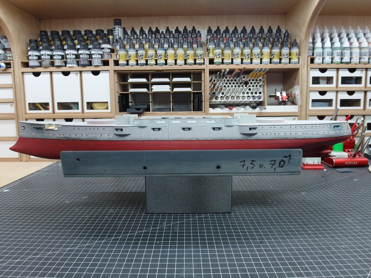
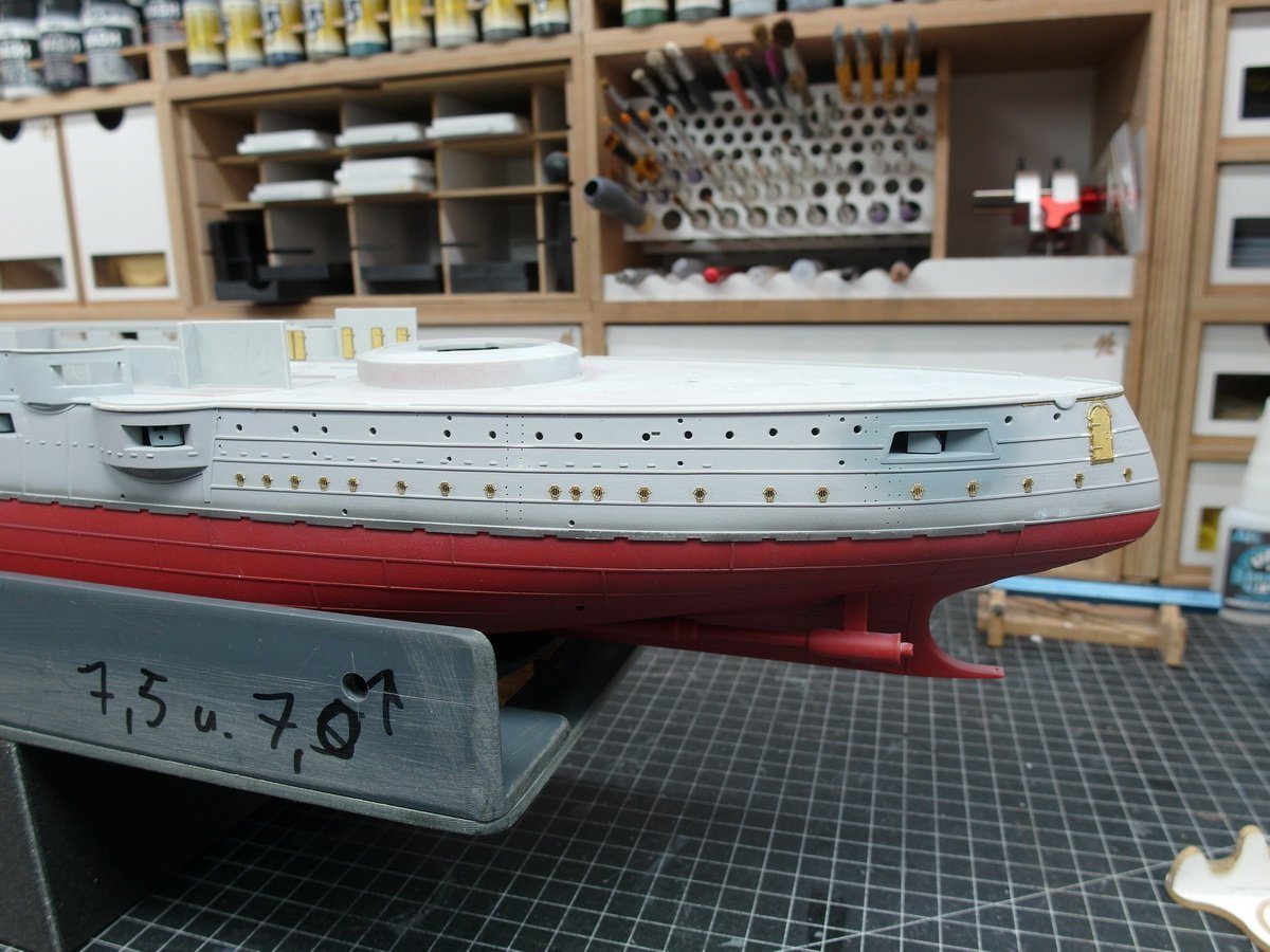
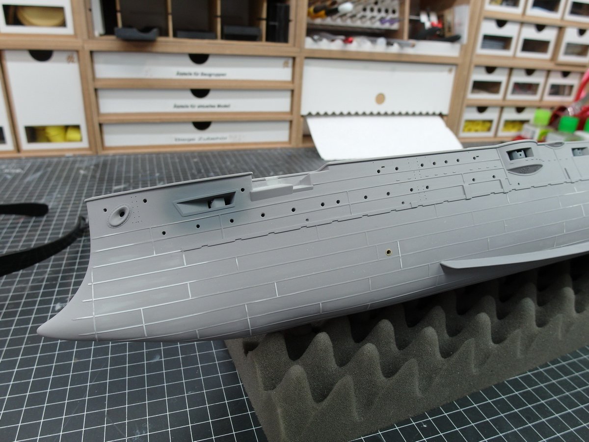
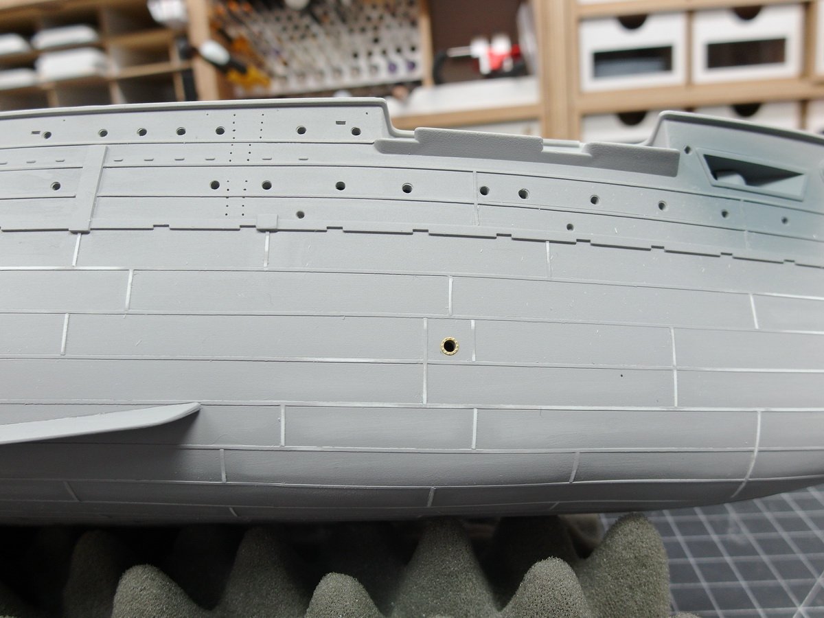
Ahoy dear model building community. Due to my wife’s illness, I’m making slow progress at the moment. But it’s nice that you can distract yourself a little by doing crafts. And so I put my ship on its side again. It was time for the final details to be added before painting. For me there are always very few. Most of it is only processed towards the end. This includes the grilles in front of the bow and stern cannons and of course the crampons. I don’t use the crampons on the etched part boards. I don’t like these one hundred percent because they are of course flat. So I prefer to take thin wire and bend it to size. In addition, crampons of different thicknesses were probably installed on the Mikasa. Documented here in two old photo clippings. The arrows point to the two types of crampons. You can really see that two different diameters were used. The crampons for climbing the torpedo net racks were much thicker. And I want to represent this using 0.2 or 0.3 mm thick wire. I initially had 0.1mm wire in mind, but that wasn’t practical because it was too unstable. ( 0,2mm is 0,007 inch and 0,3mm is 0,01 inch) And this is how it turns out after checking the primer. I like it quite a bit. A few small irregularities can still be seen and will be removed with fine 1000 grit sandpaper after it has dried. But I think you can guess that the different strength crampons are like the original.
- 26 replies
-
- 8
-
-
- Russo-Japanese War
- Mikasa
- (and 2 more)
-
madtatt reacted to a post in a topic:
HIJMS MIKASA 1902 by Jeff59 - HobbyBoss - 1/200 - PLASTIC
-
madtatt reacted to a post in a topic:
HIJMS MIKASA 1902 by Jeff59 - HobbyBoss - 1/200 - PLASTIC
-
madtatt reacted to a post in a topic:
HIJMS MIKASA 1902 by Jeff59 - HobbyBoss - 1/200 - PLASTIC
-
madtatt reacted to a post in a topic:
HIJMS MIKASA 1902 by Jeff59 - HobbyBoss - 1/200 - PLASTIC
-
madtatt reacted to a post in a topic:
HIJMS MIKASA 1902 by Jeff59 - HobbyBoss - 1/200 - PLASTIC
-
madtatt reacted to a post in a topic:
HIJMS MIKASA 1902 by Jeff59 - HobbyBoss - 1/200 - PLASTIC
-
madtatt reacted to a post in a topic:
HIJMS MIKASA 1902 by Jeff59 - HobbyBoss - 1/200 - PLASTIC
-
madtatt reacted to a post in a topic:
HIJMS MIKASA 1902 by Jeff59 - HobbyBoss - 1/200 - PLASTIC
-
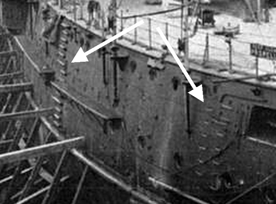
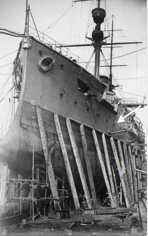
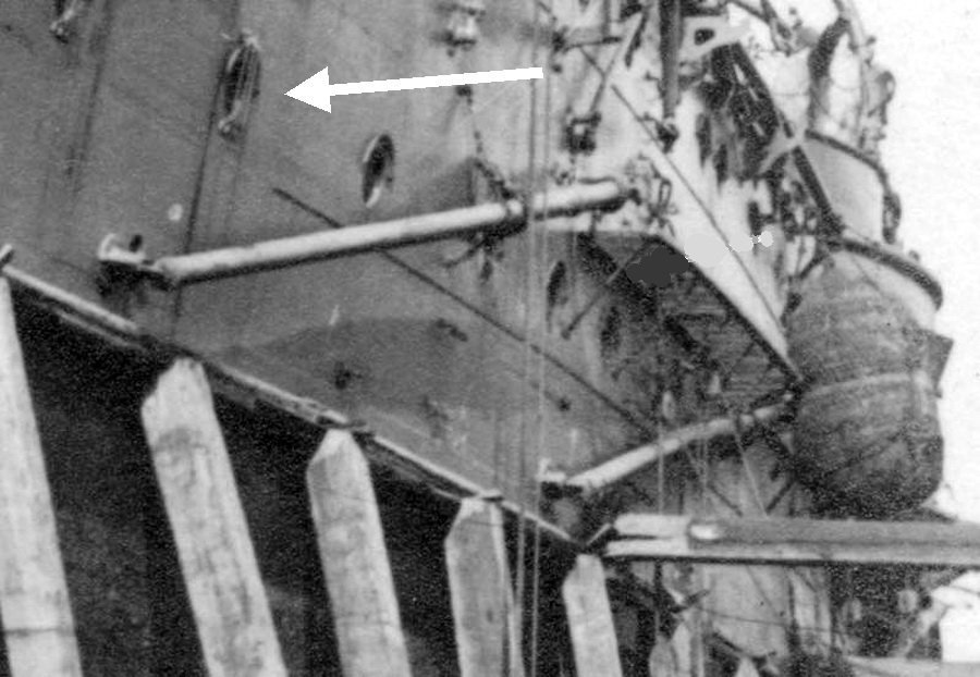
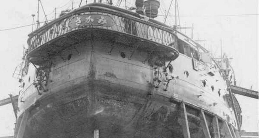
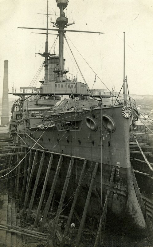
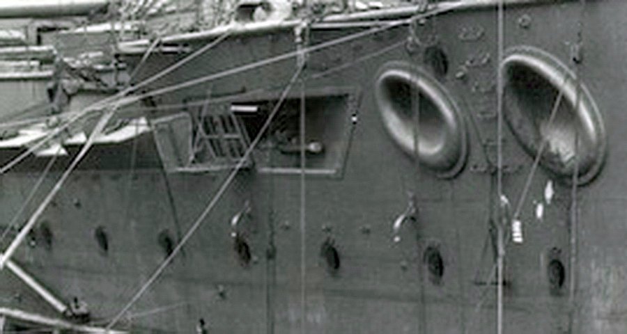
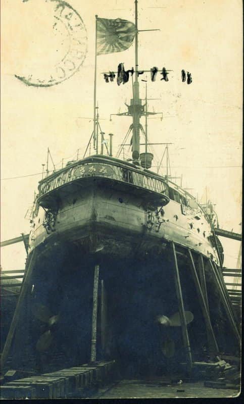
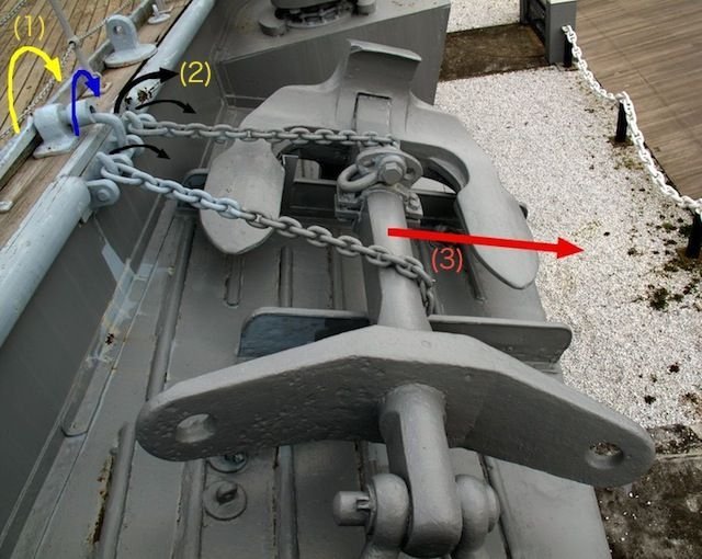
Ahoy everyone. One of the reasons why I bother to publish my construction reports in forums is the subsequent exchange of ideas. Construction phases should be questioned from time to time, this stimulates research and thus increases the historical correctness of the models. In another forum the question arose about the purpose of the barred portholes. That didn’t give me peace of mind. The grid would only have had a right to exist at the height of the anchors. On this ship, the anchors were pulled back on board with the davits and an anchor could have hit the hull or the porthole. In addition, the anchor chains ran past the portholes. So I looked at everything I had in detail again. The fact is that during active service, here in 1921, the front portholes were barred. You can see this in the following and best quality picture of the ship that I have. It was taken in Vladivostok in 1921. Here the section is enlarged. So there were bars, but you can’t really tell whether all the lower portholes on the bow were barred. Then this picture of the stern, also taken in Vladivostok in 1921. So quite late in their active service. She was in this dry dock for repairs. Here the enlarged and brightened section shows that there were definitely no grilles in front of the portholes at the rear. So the question arises as to where this protective measure went. The anchor area would be logical. I found the solution in the following picture. The white arrow points to the same porthole in both photos. You can clearly see here that the portholes were protected with grilles right up to the anchor storage areas. So get it down again. Good thing I don’t use superglue. So no act. Again, sanded clean and everything from the beginning. And replaced everything at the rear. Thank God Pontos isn’t stingy with his portholes. There are more than enough of them. Completed.
- 26 replies
-
- 7
-
-
- Russo-Japanese War
- Mikasa
- (and 2 more)
-
Thank you very much for your participation. I should send greetings from my wife to the model makers. 😘
-
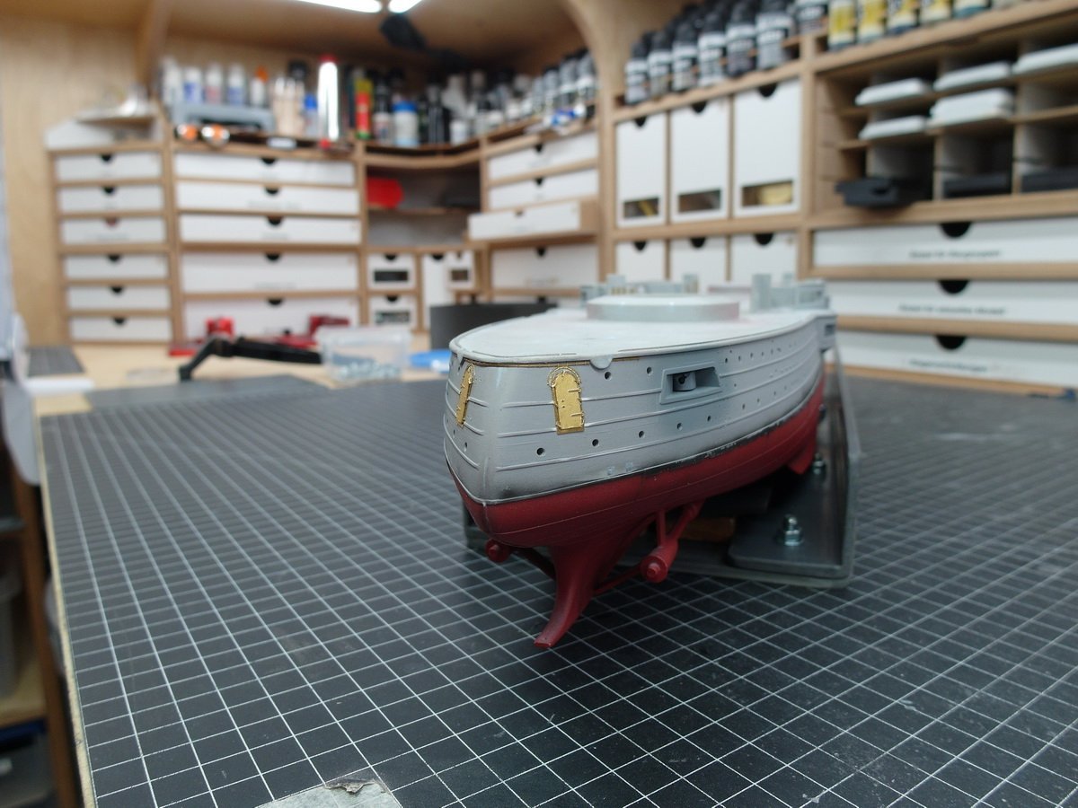
Thank you, both of you. And now a little mini update. The portholes are closed on the port side. At the bow. I noticed another error in the model amidships. Three more portholes were missing from the upper row of casemates. They cannot be seen in the pictures from back then. Most of the images of the ship are of poor quality and taken from a great distance. There are only some in a decent resolution very close up from the front. But of course you can’t see the casemates from the side. But on the museum ship. And since I can’t imagine that they were added later, I adopted them. And the portholes at the stern.
- 26 replies
-
- 5
-
-
-
- Russo-Japanese War
- Mikasa
- (and 2 more)
-
Thank you, James. Unfortunately I couldn't take part because my wife was ill and had to have an operation that weekend.
-
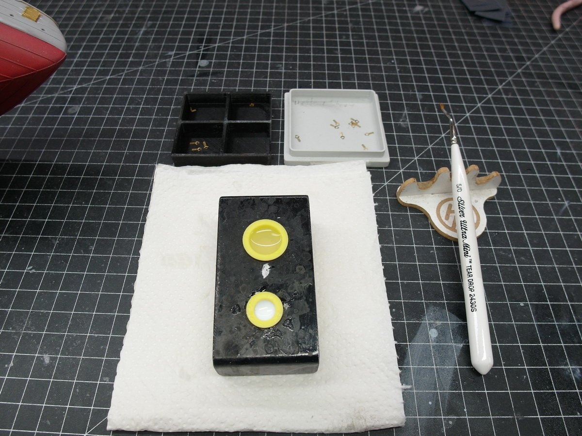
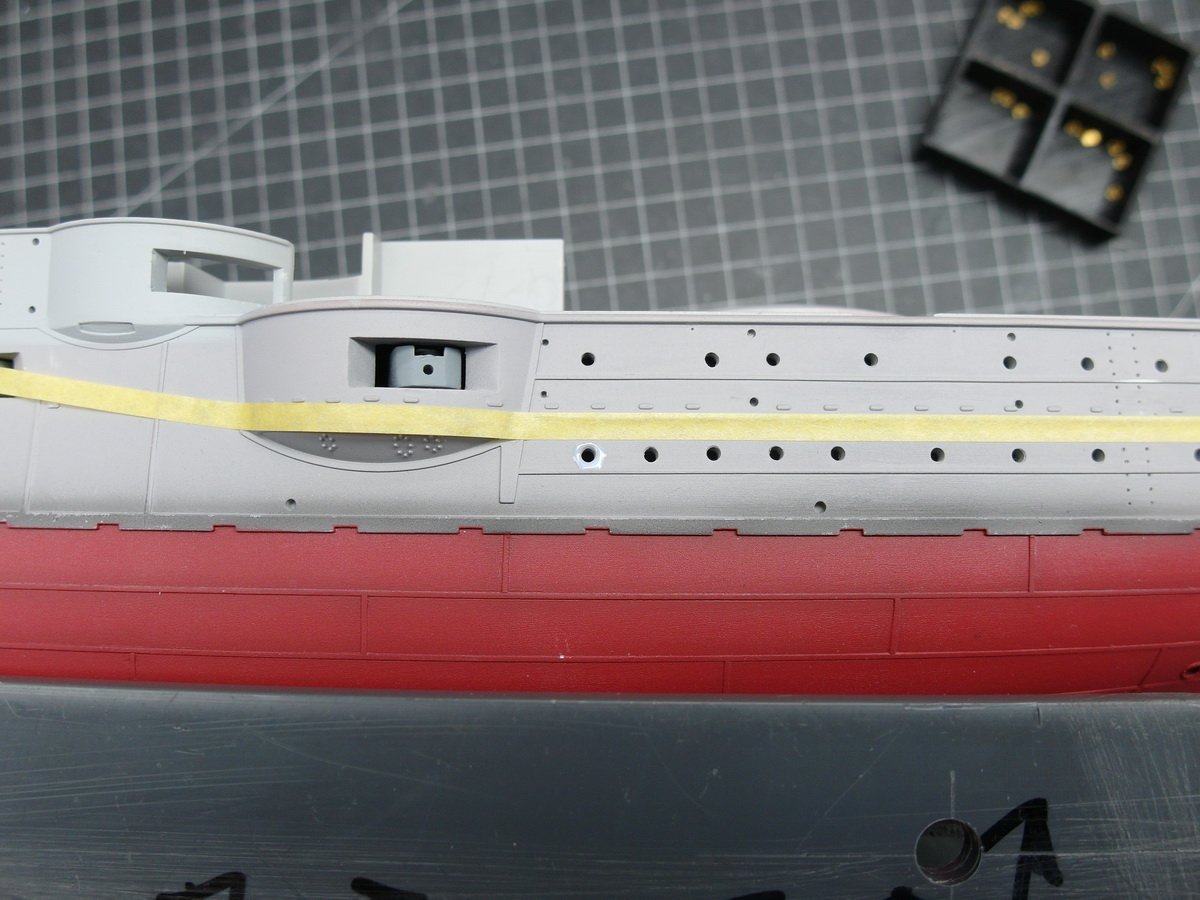
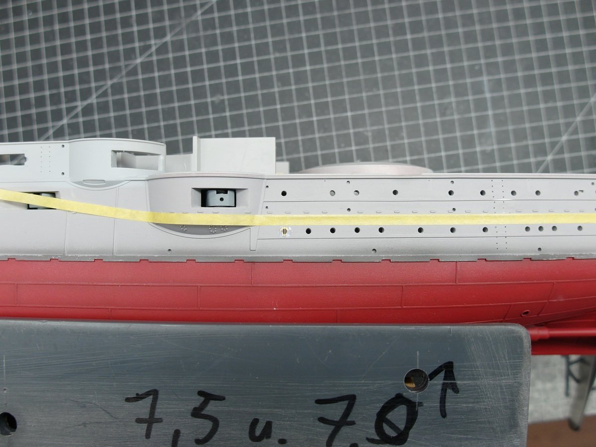
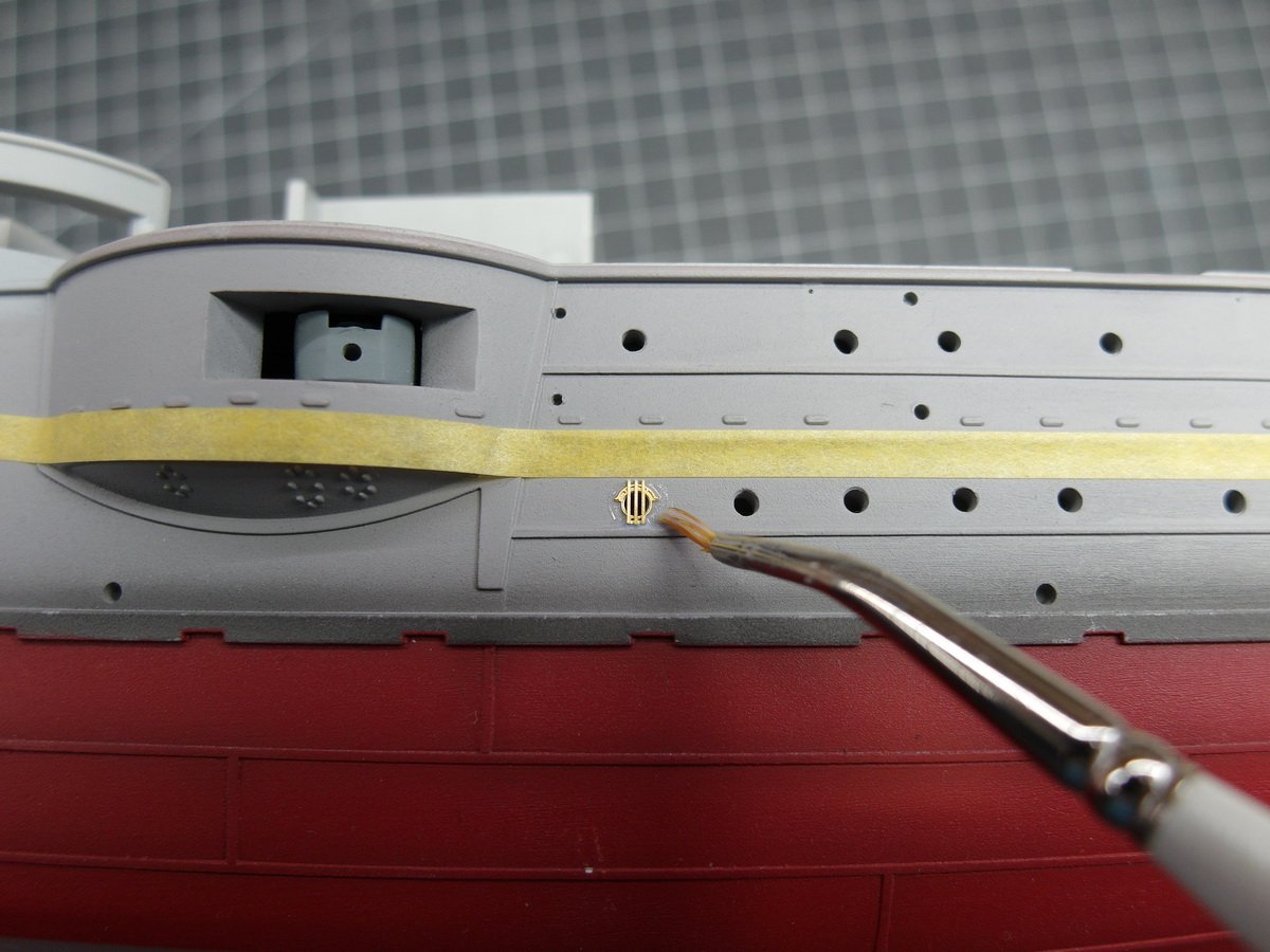
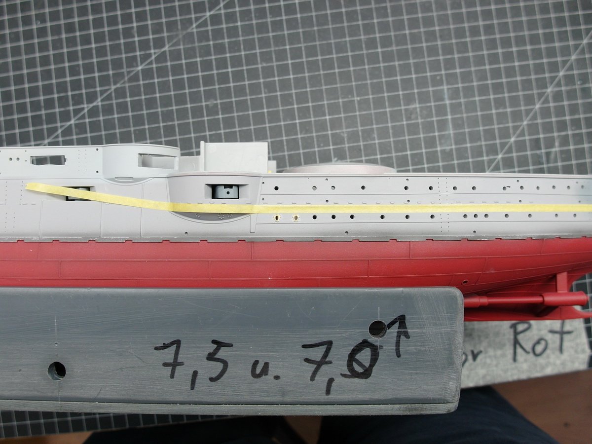
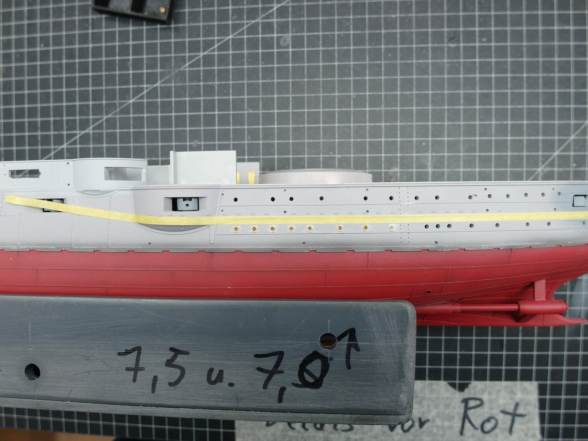
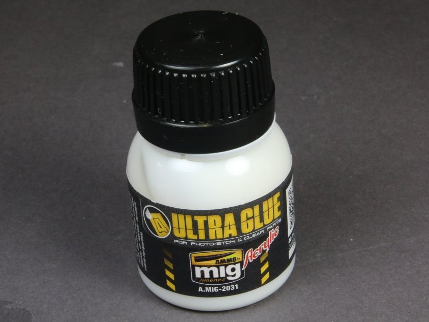
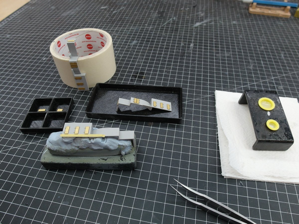
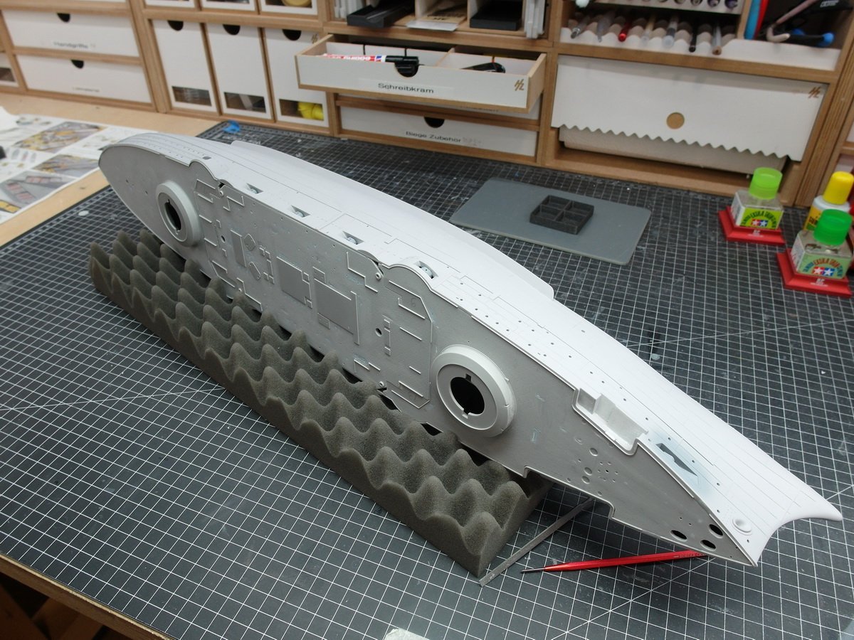
Off to the dry dock with the Mikasa. There’s enough space in here on the port and starboard sides to protect the ship while you’re tinkering without it becoming too big and unwieldy.. This means it can be safely laid on its side, for example to work on the portholes. I can also attach sheet pile walls of different heights to further increase the protection at the top. Let’s attach the first large etched parts. The anchor supports… …and the doors at the rear. The ship also had electrical cables all around the back. What purpose they had, however, is unknown to me. It will not have been demagnetizing cables. In another forum a user asked me how I work with acrylic etched part glue. I would like to show this using the rain deflectors of the portholes as an example. We need an old brush, some paper towel, a little water and the glue. I dilute this until it has about the consistency of buttermilk. Then I draw a guide line with adhesive tape to attach the etched parts neatly and straight. Now I put a ring of glue around the porthole. Then in with the etched part. The big advantage is that you have a very long time to properly align the component. Completely in contrast to superglue. After I have aligned it, I pick up the excess glue again with the brush that has been cleaned in water and dried on the paper towel. I can easily remove any edges of the glue with a dampened brush. This is also not possible with superglue. The slight shine of the dried glue can no longer be seen after painting. And so you get rain deflectors on the portholes like a string of pearls, which are also glued on extremely neatly.
- 26 replies
-
- 7
-
-
- Russo-Japanese War
- Mikasa
- (and 2 more)
-
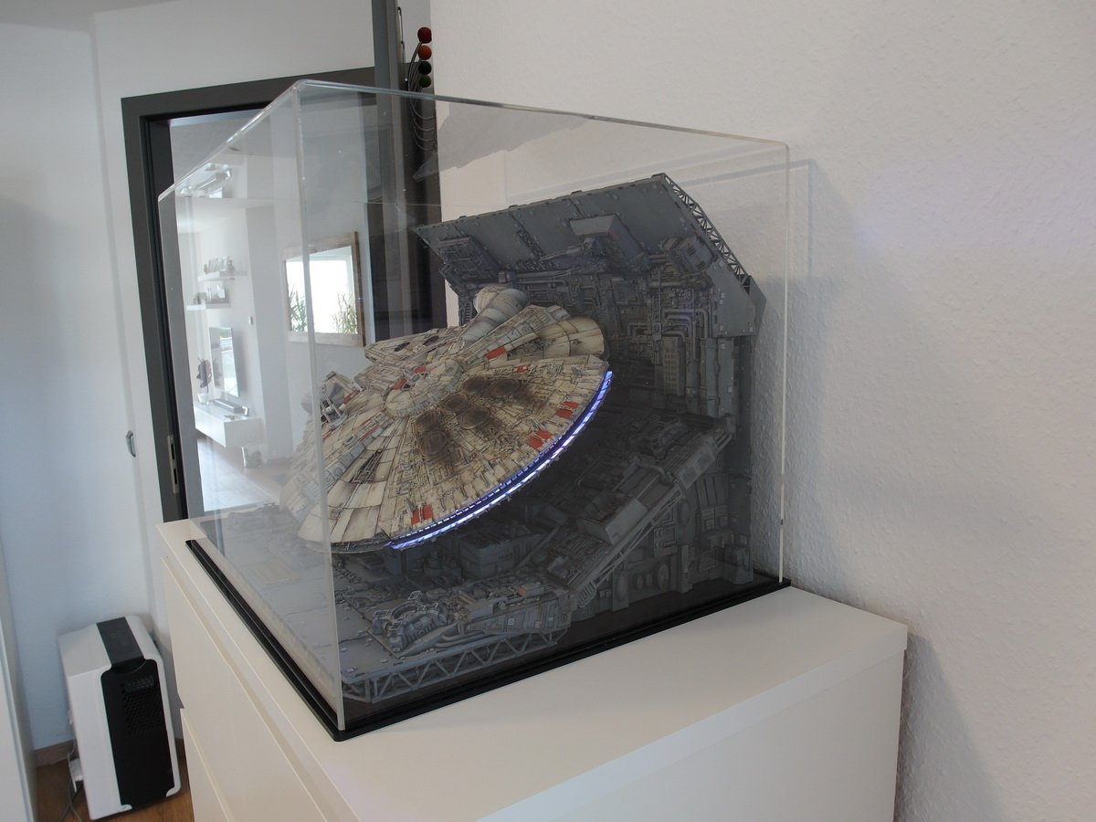
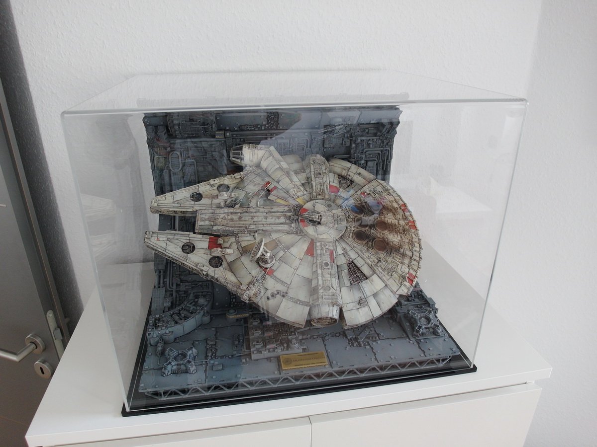
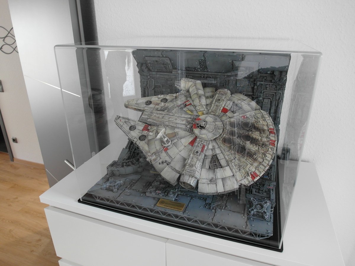
Here’s another little reference. The little bird has come into its cage. It will stay there until the next exhibition. Electronics work without problems.
- 71 replies
-
- 15
-
-
-
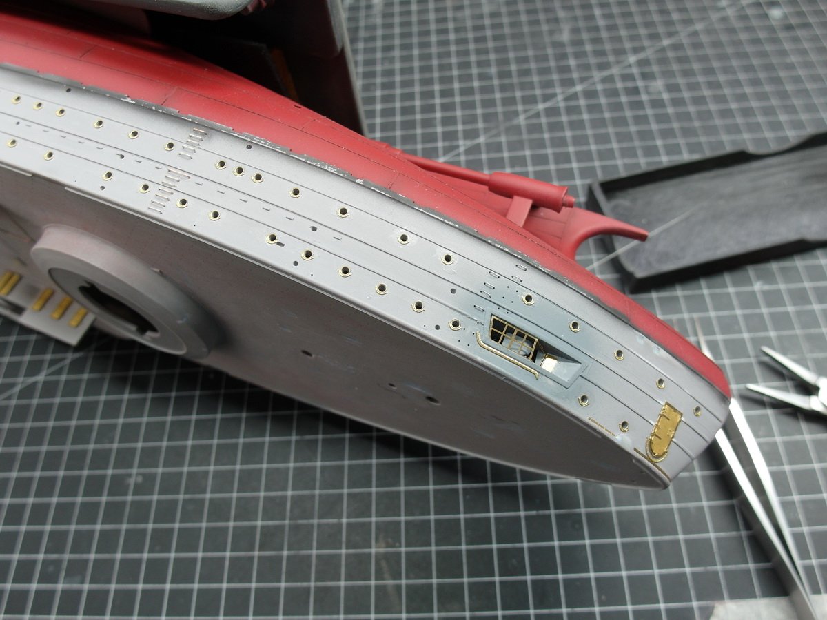
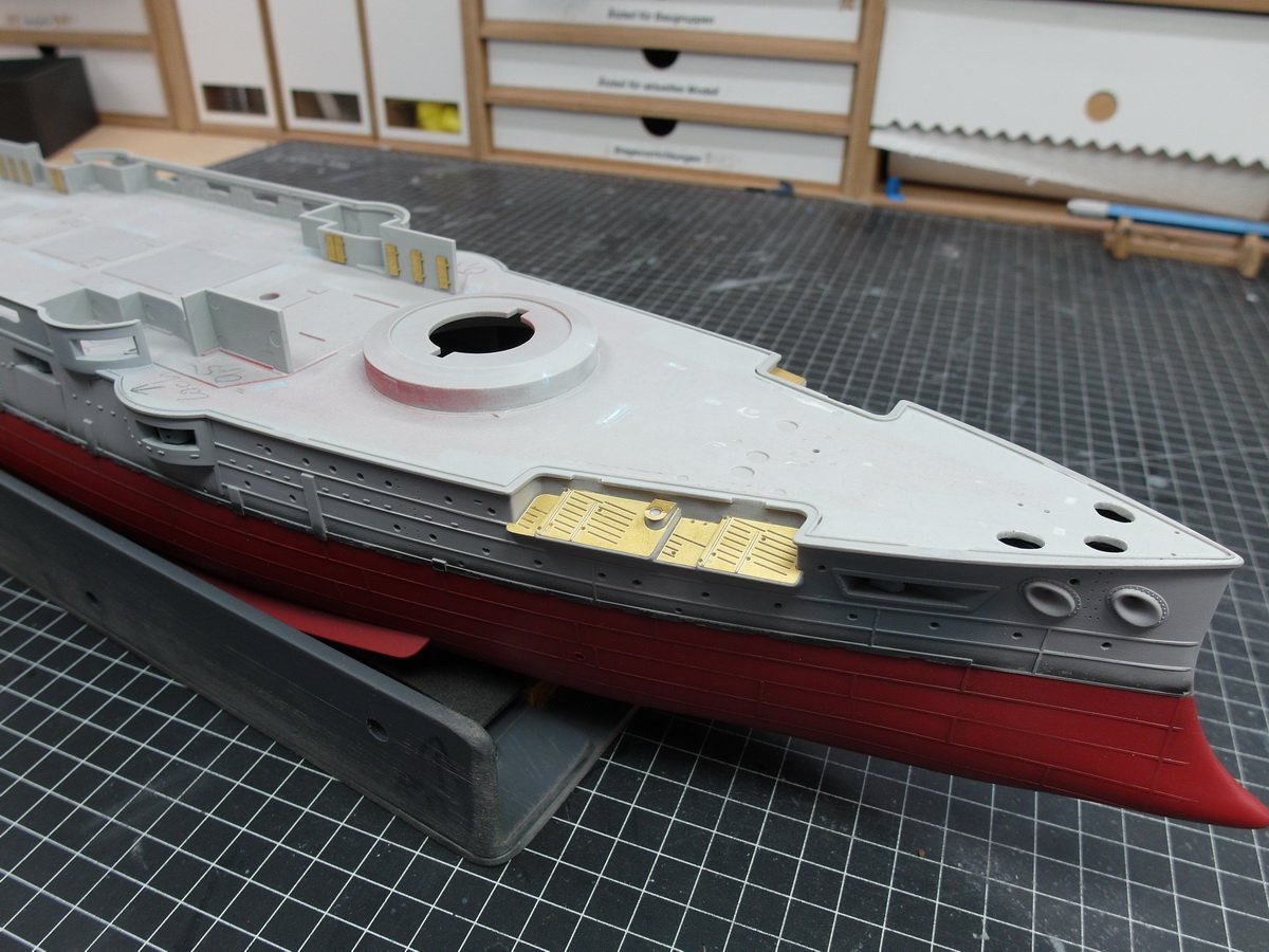
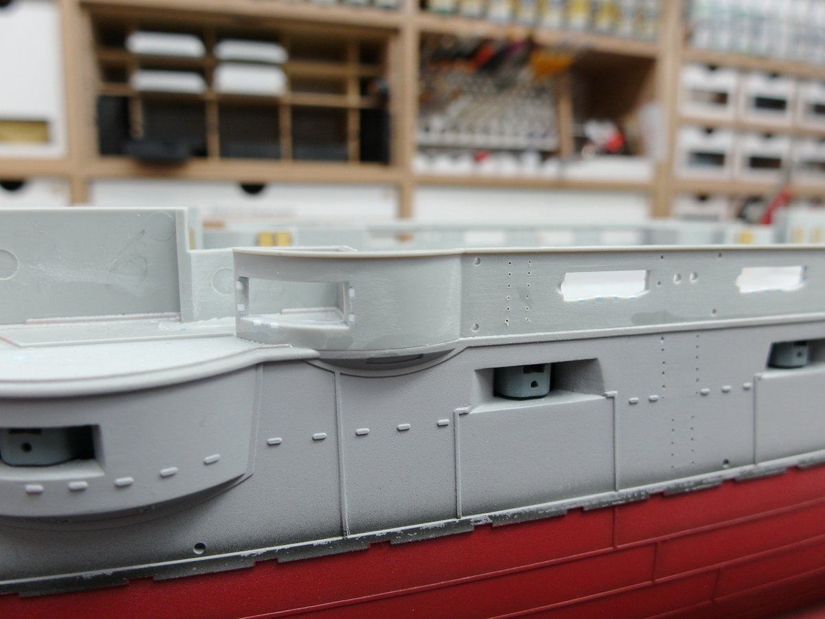
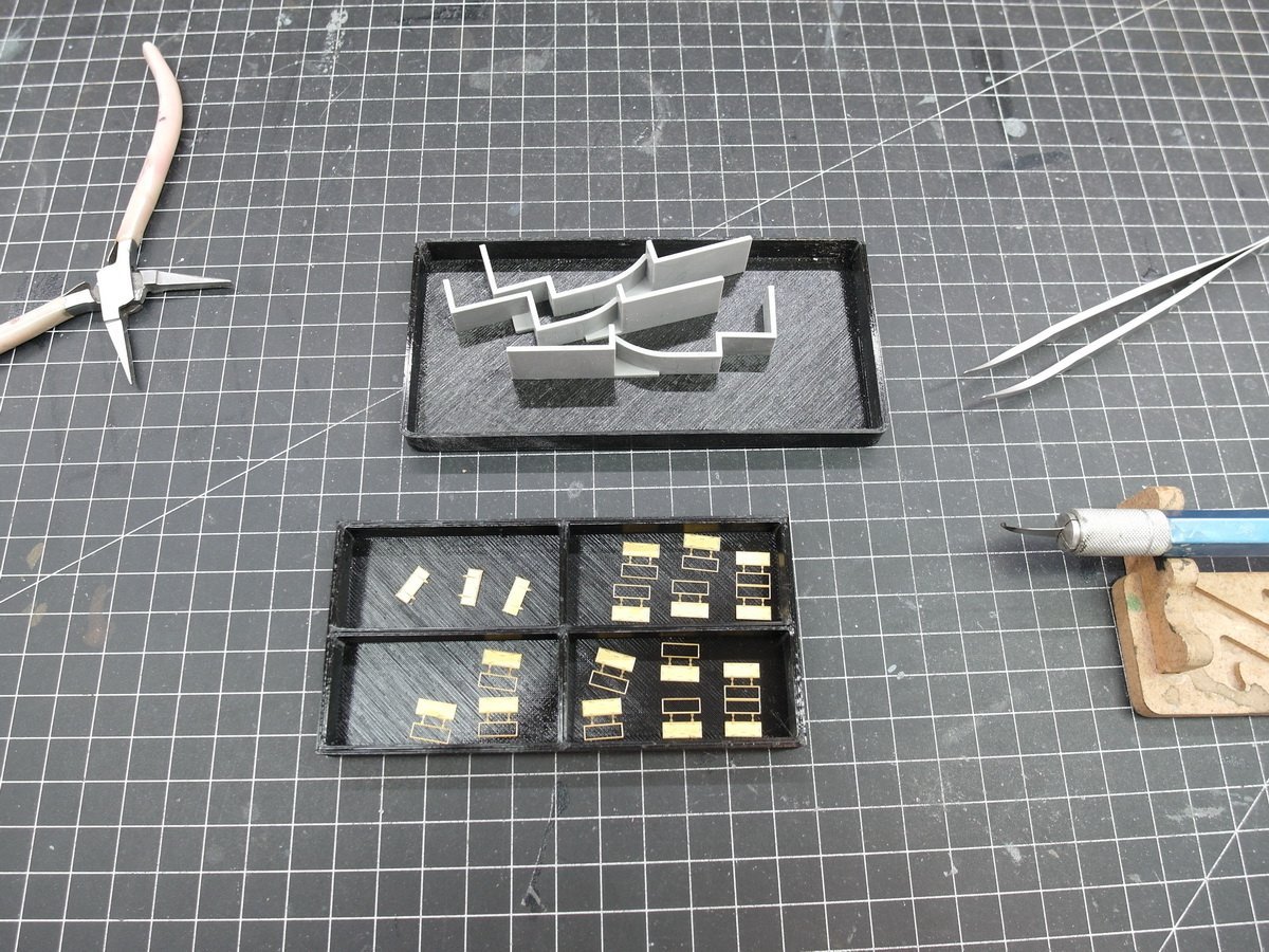
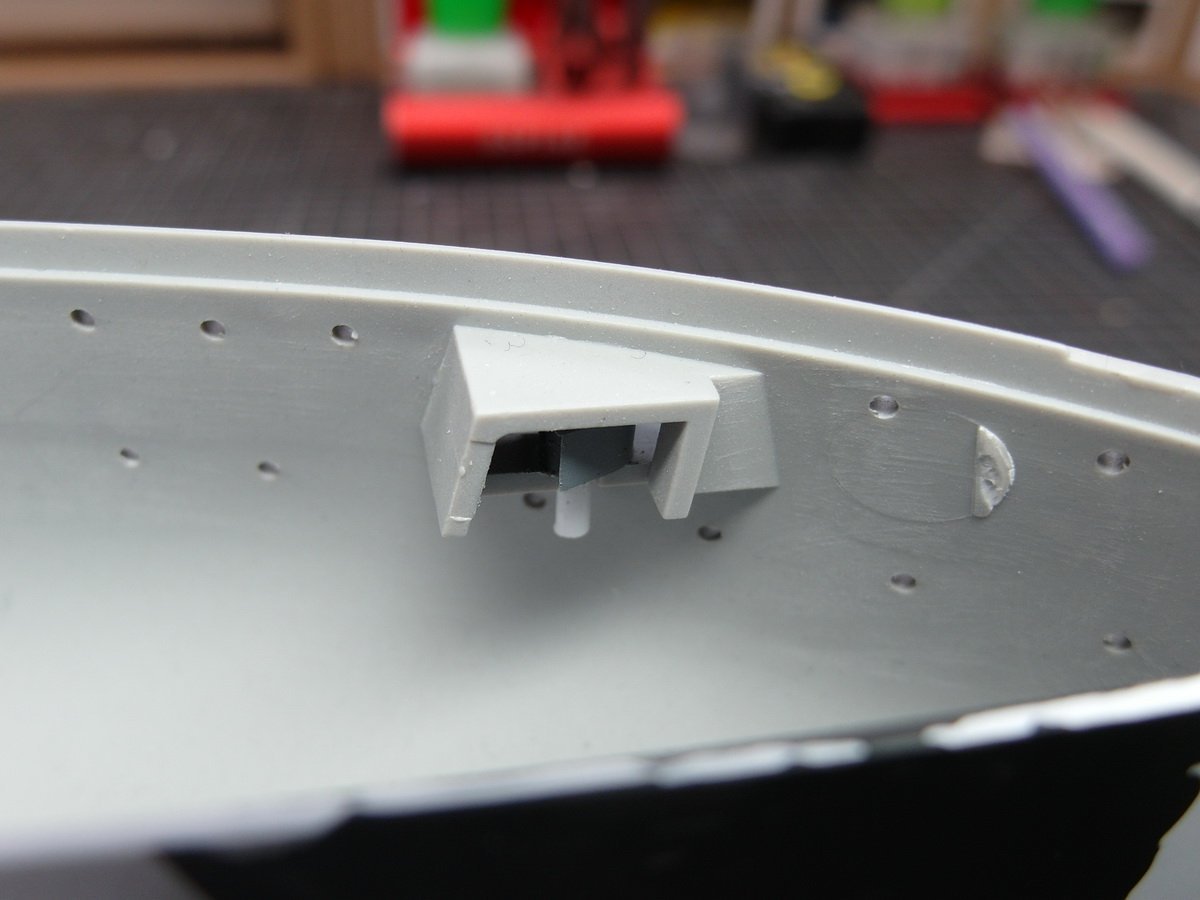
The holes for the crampons were still missing on the upper casemates. I repeat myself, but this is one of Ponto’s great strengths. The drilling templates! Simply fix it with an adhesive strip and off you go… Next I checked the wooden deck amidships. It had to be trimmed a bit to get it to fit properly. Because of the slightly different approach, I have little leeway when installing the parts. But done satisfactorily. So I was able to add the next floor. Additional parts placed on top to check whether everything is in the correct position. Everything fits perfectly. Here are the pictures to show why I go to this length. The slits in the four round casemates would still be manageable. But this one isn’t very nice. I think this is better. After sanding three times… …and prime, I am very satisfied. And I especially like this one a lot better now. The extra two days of effort were worth it.
- 26 replies
-
- 5
-
-
- Russo-Japanese War
- Mikasa
- (and 2 more)
-
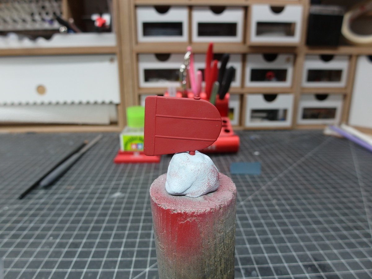
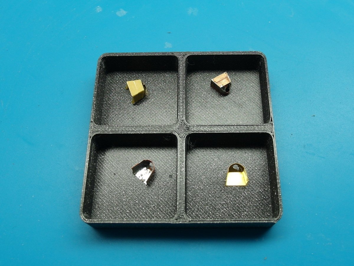
Next I went to the ship’s rudder. I had actually lost sight of that a bit. Never mind, styrene attached and painted red. Then to the upper casemates. Unnecessary holes closed again. Sanded and found to be good. So the etched parts battle could finally begin. The MK1 set has already scored its first points. Shortly before I had sanded away the rather rough details, I thought about taking a quick photo of them. Pontus had not planned anything here. Incomprehensible, even if you can hardly see it on the finished model. So, one to zero for KA Models. Still processing the remaining doors… Then the first superstructures can go on the deck. I will probably lay more electrical cables when my 0.1mm wire arrives.
.JPG.43f13cca2aefc25e0c9d63a50f04386f.JPG)
- 26 replies
-
- 4
-
-
- Russo-Japanese War
- Mikasa
- (and 2 more)
-
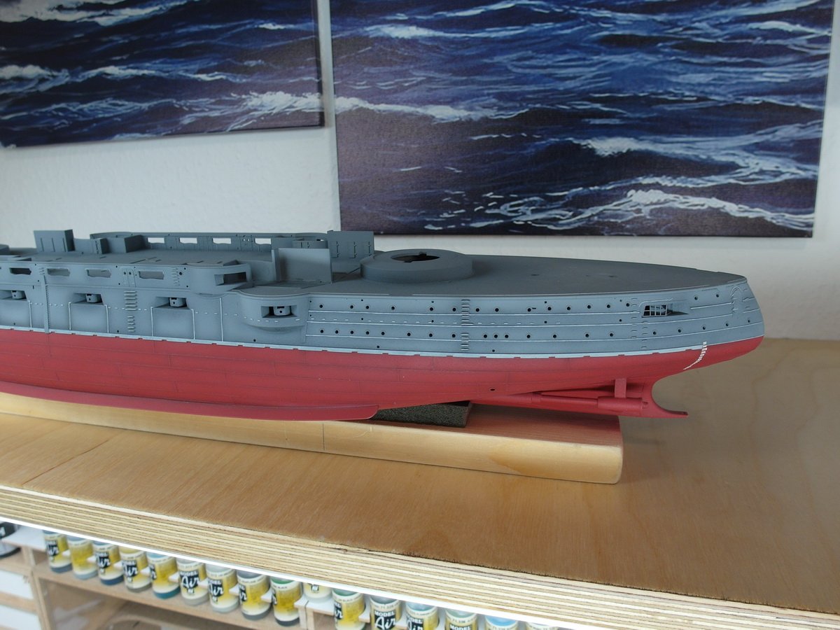
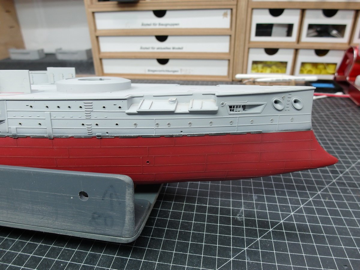
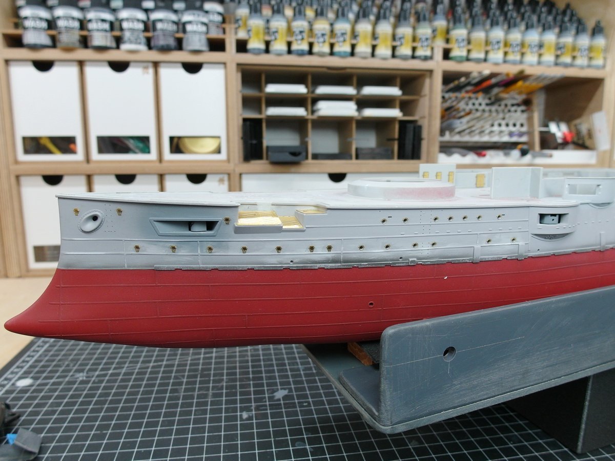
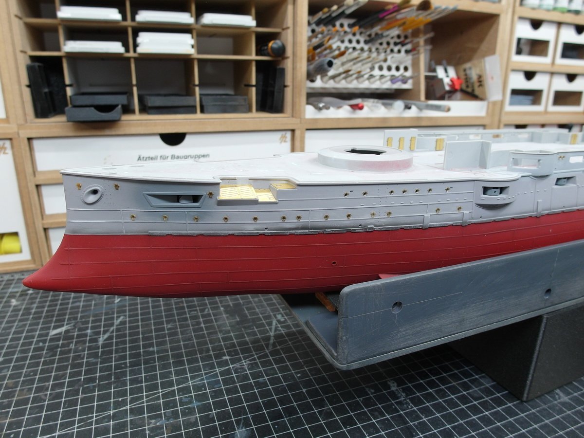
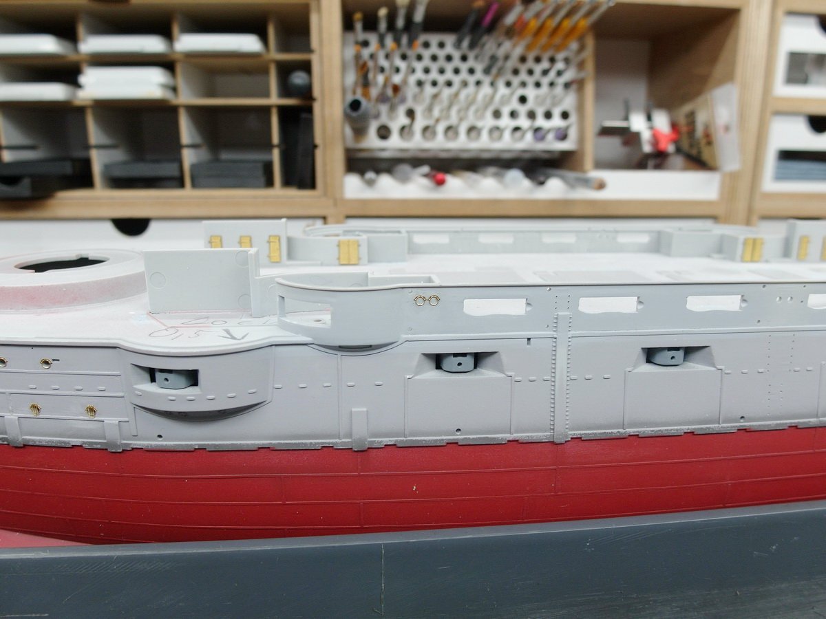
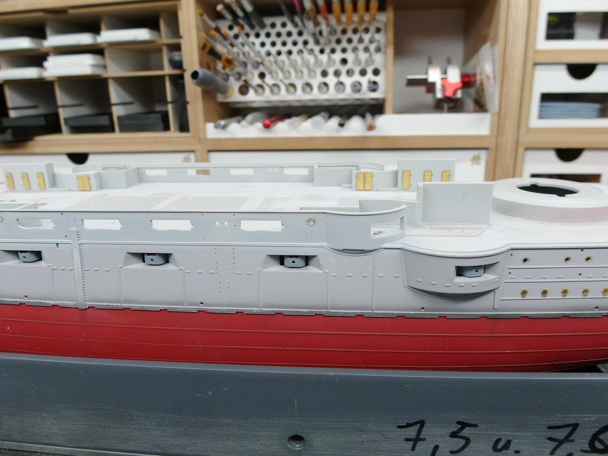
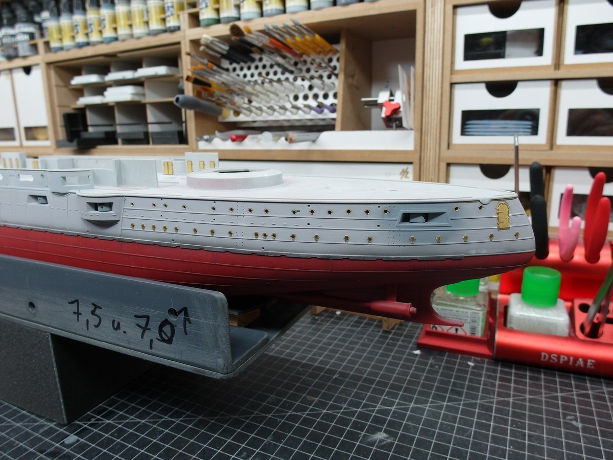
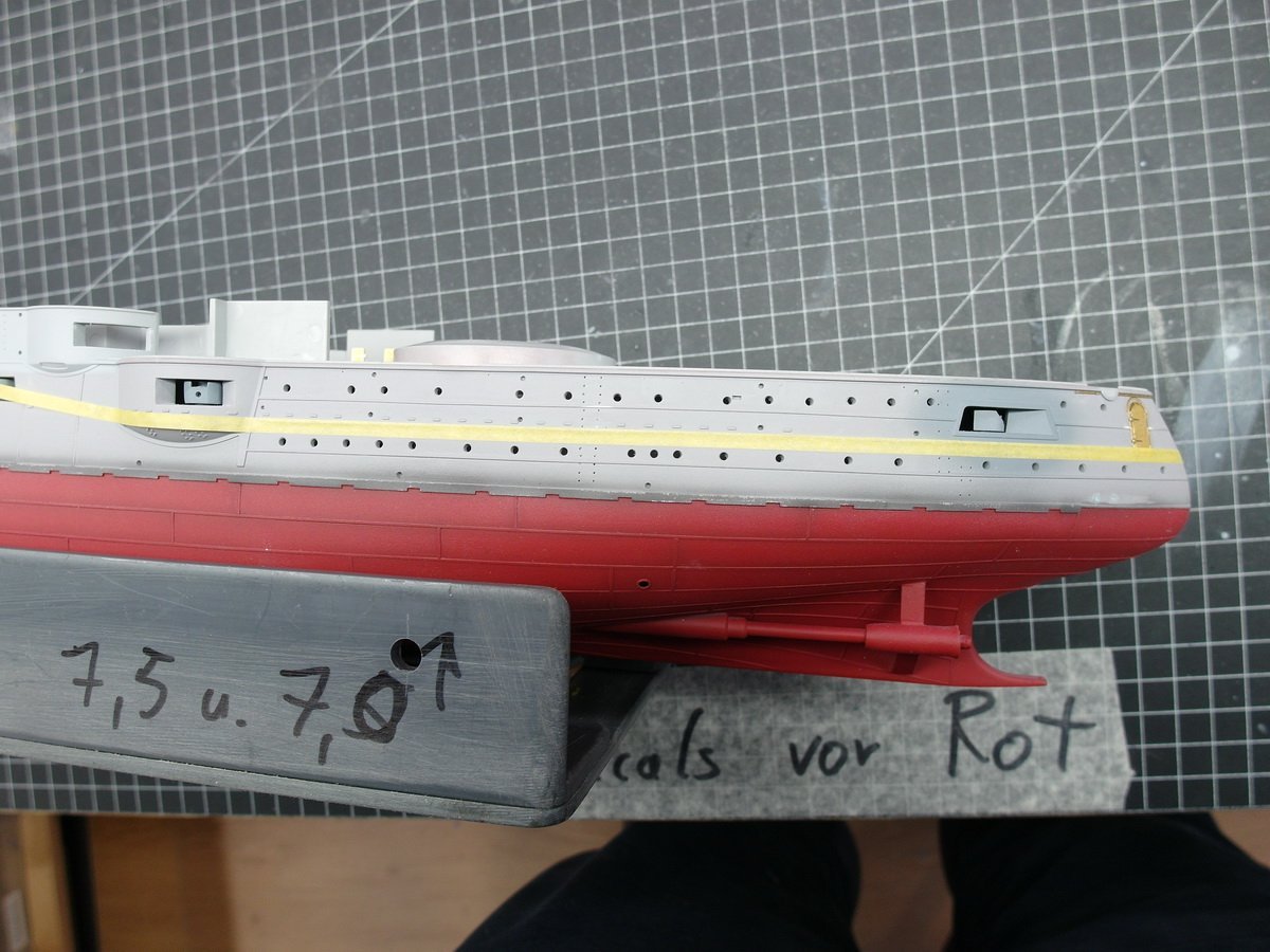
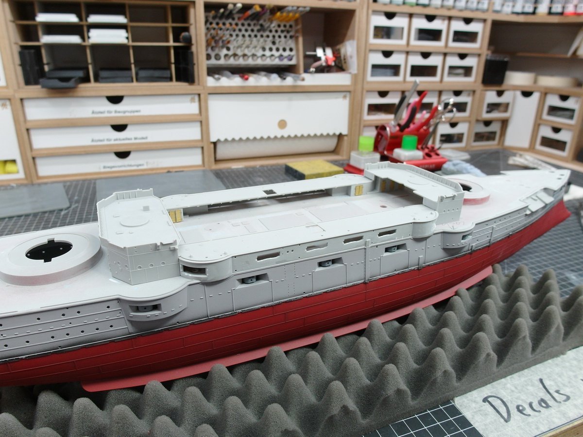
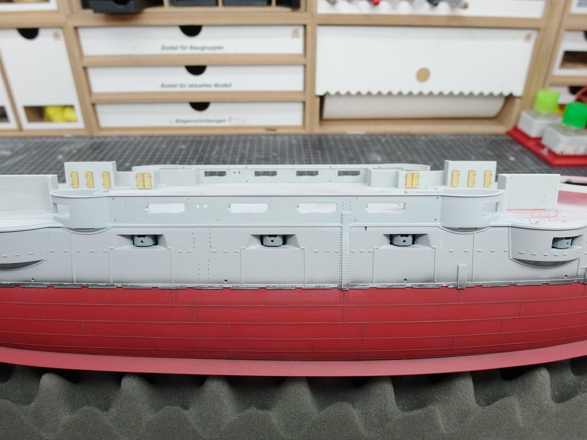
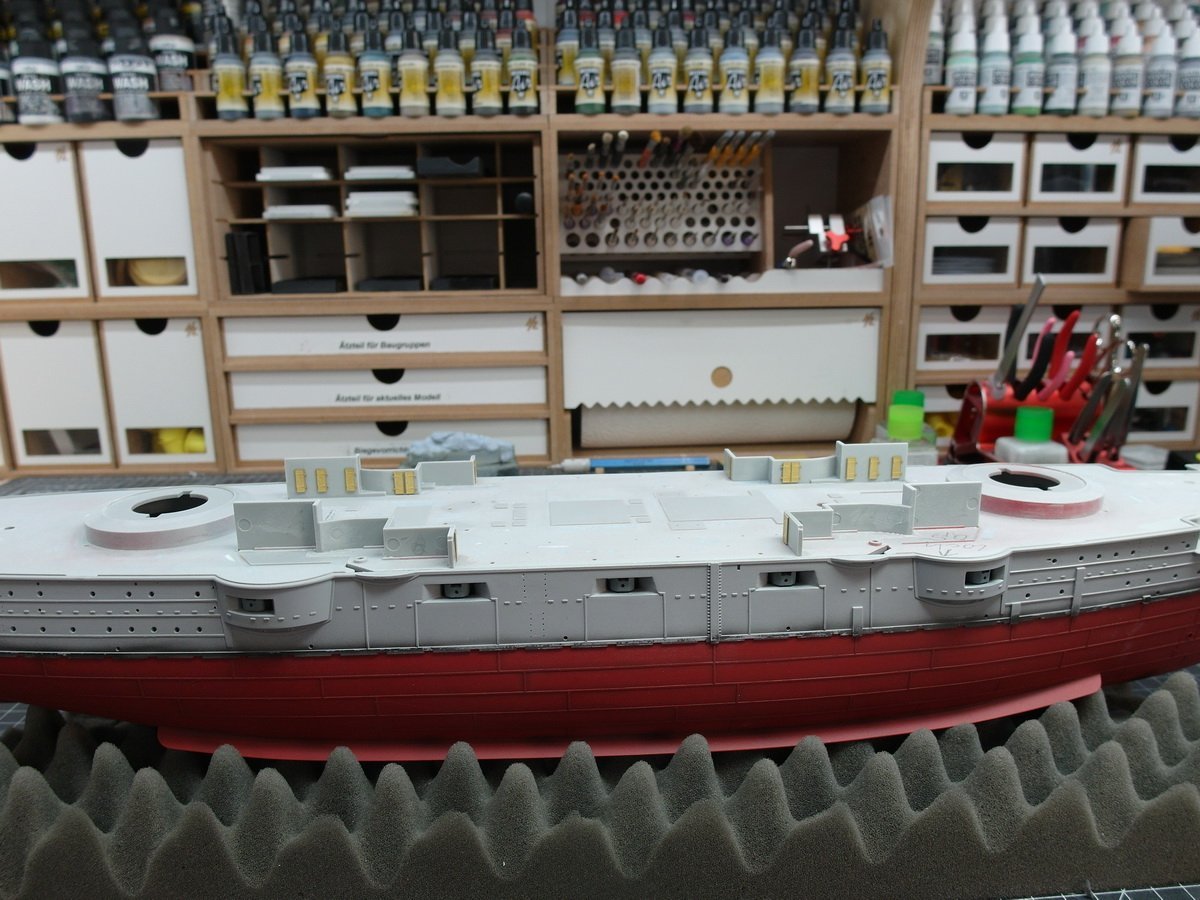
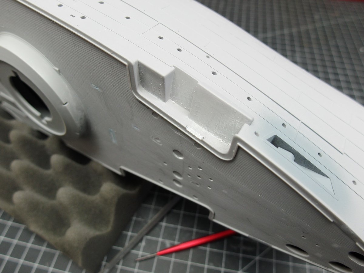
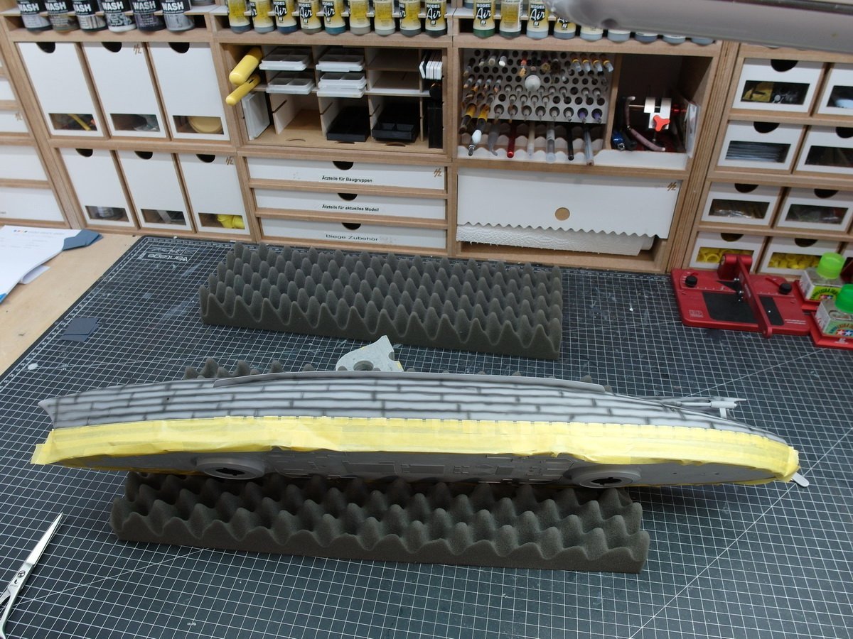
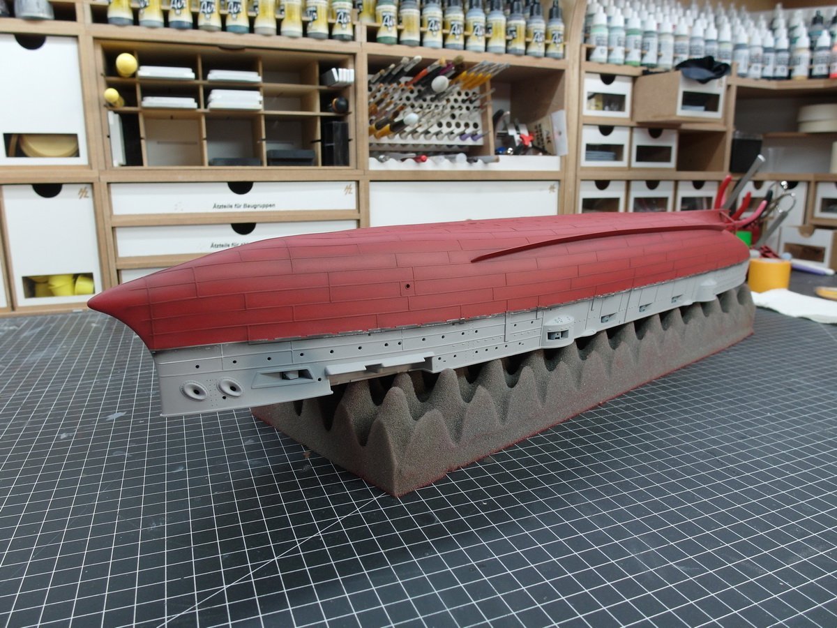
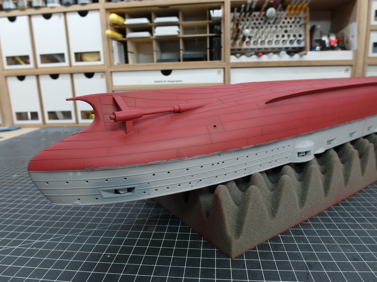
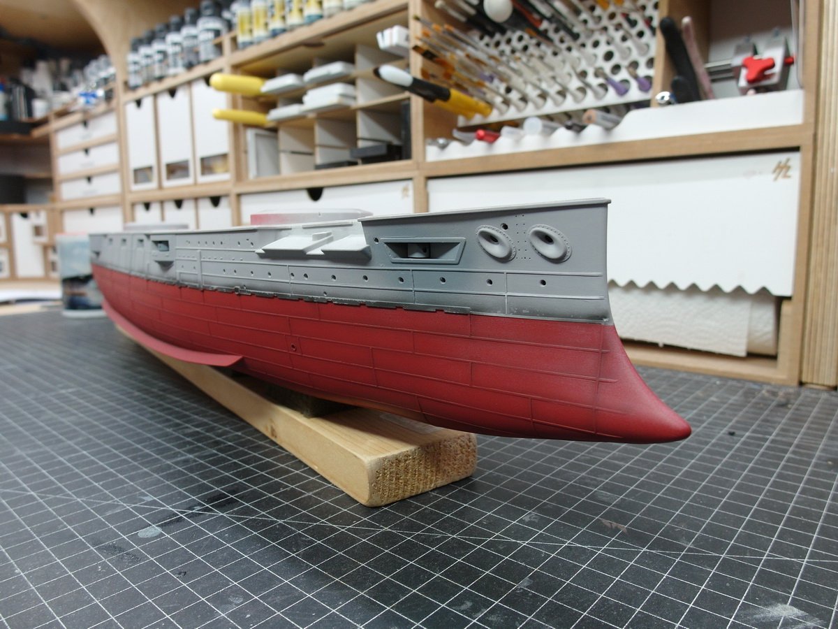
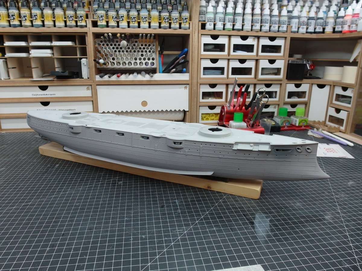
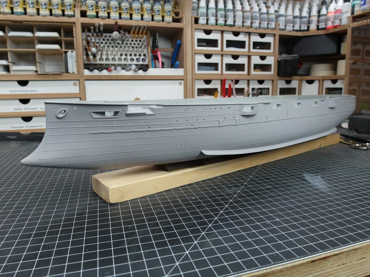
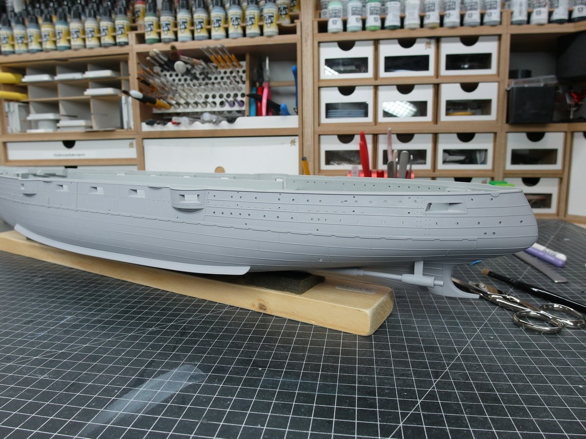
Thank you very much, Yves. I would be very happy to read your construction report on the Mikasa here. Continue with additional small details. The next picture shows why I add large parts like gun barrels as late as possible. I would like to implement this device with which the anchor was lowered into the water. To do this I first have to remove material from the fuselage. Then all profiles are checked again and some are sanded down a little further The torpedo tube opening also has a riveted ring. On to preshading. And then tape it off. I’m doing this relatively precisely, even though I’m only in the basic color. Of course I could spray the red without masking it off, but then too many layers would overlap afterwards and the whole thing would be too thick for me. And now the antifouling paint is on the underwater hull. The waterline is running great. Profiles attached at the correct height. Here are the two recesses for the side with the double anchor. I really like the structure I made from the styrene profiles. And the preshading also comes into its own. Now we continue with the details on the upper ship.
- 26 replies
-
- 9
-
-
-
- Russo-Japanese War
- Mikasa
- (and 2 more)
-
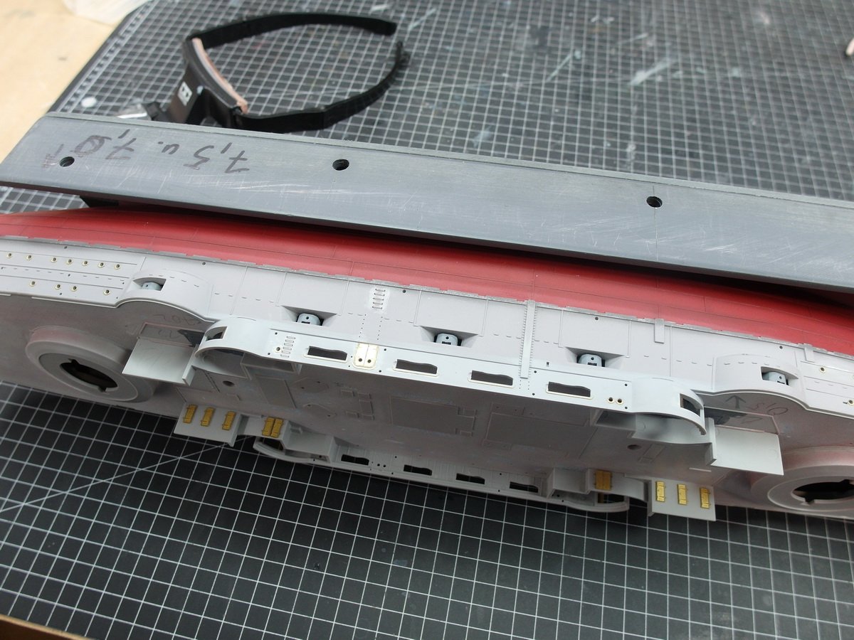
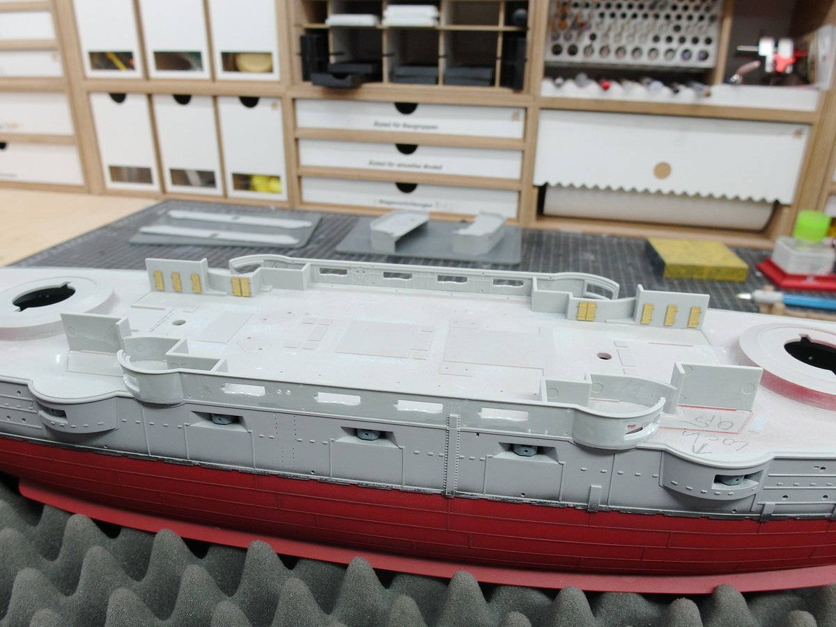
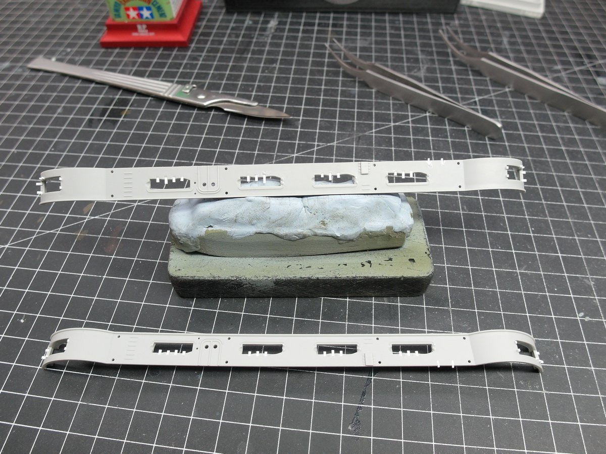
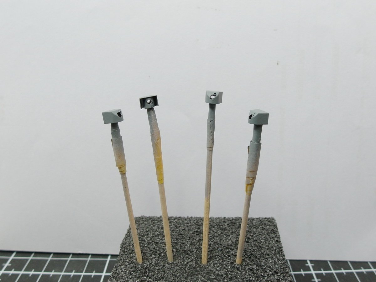
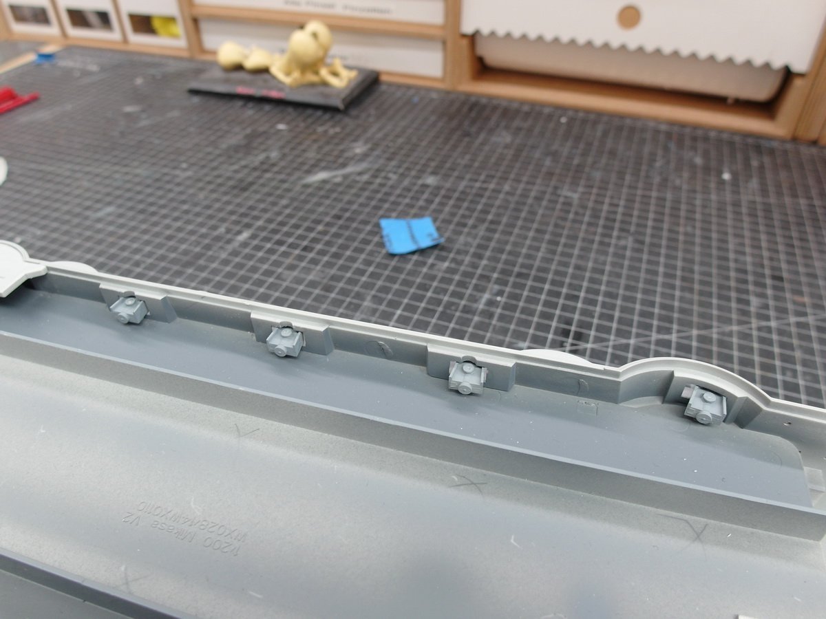
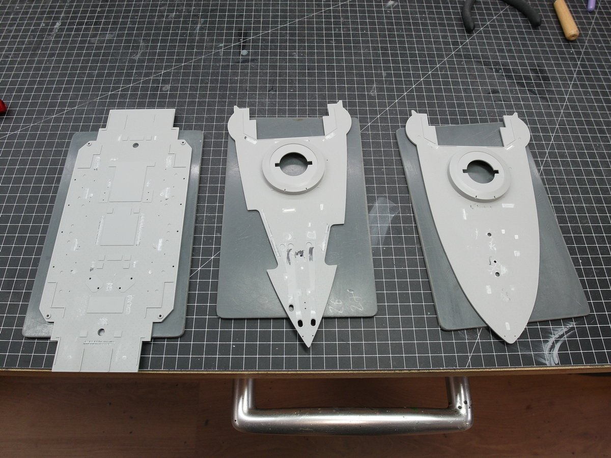
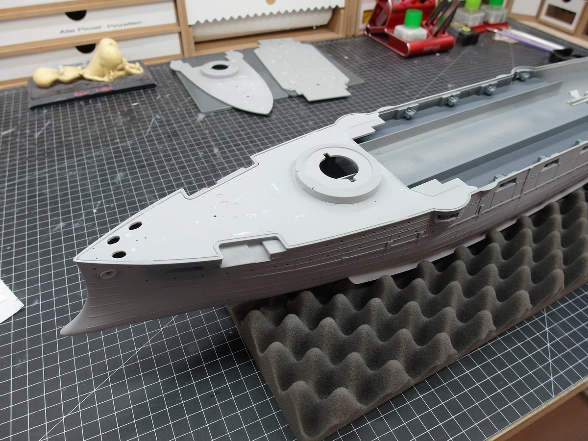
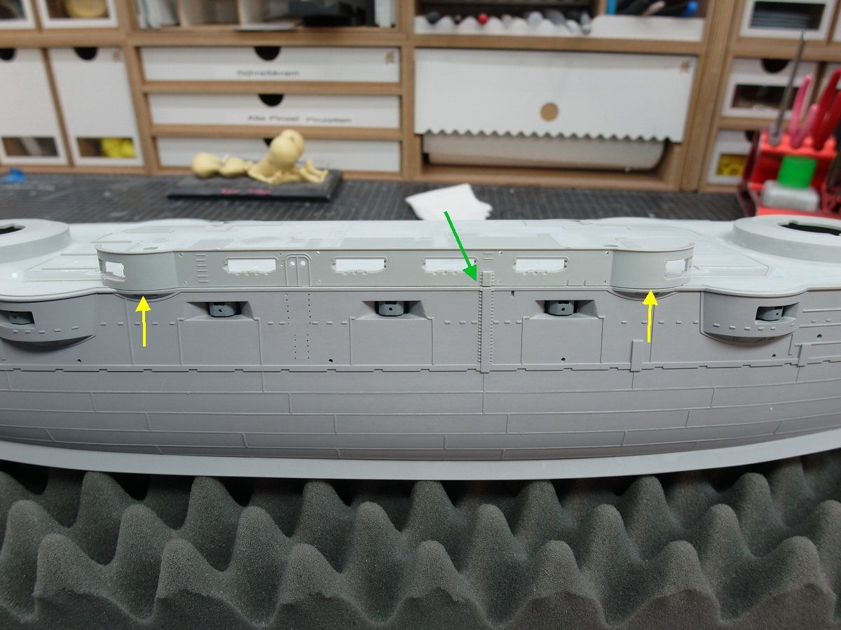
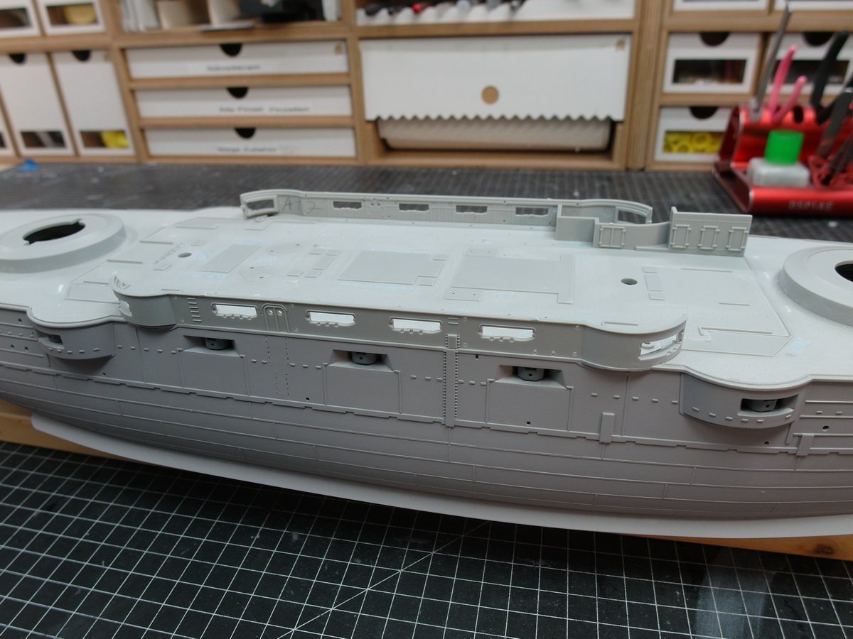
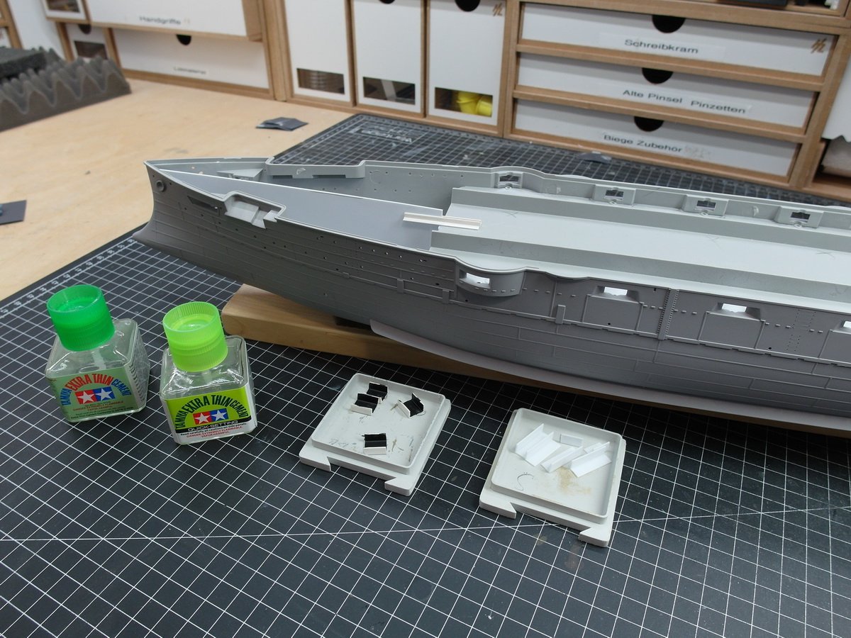
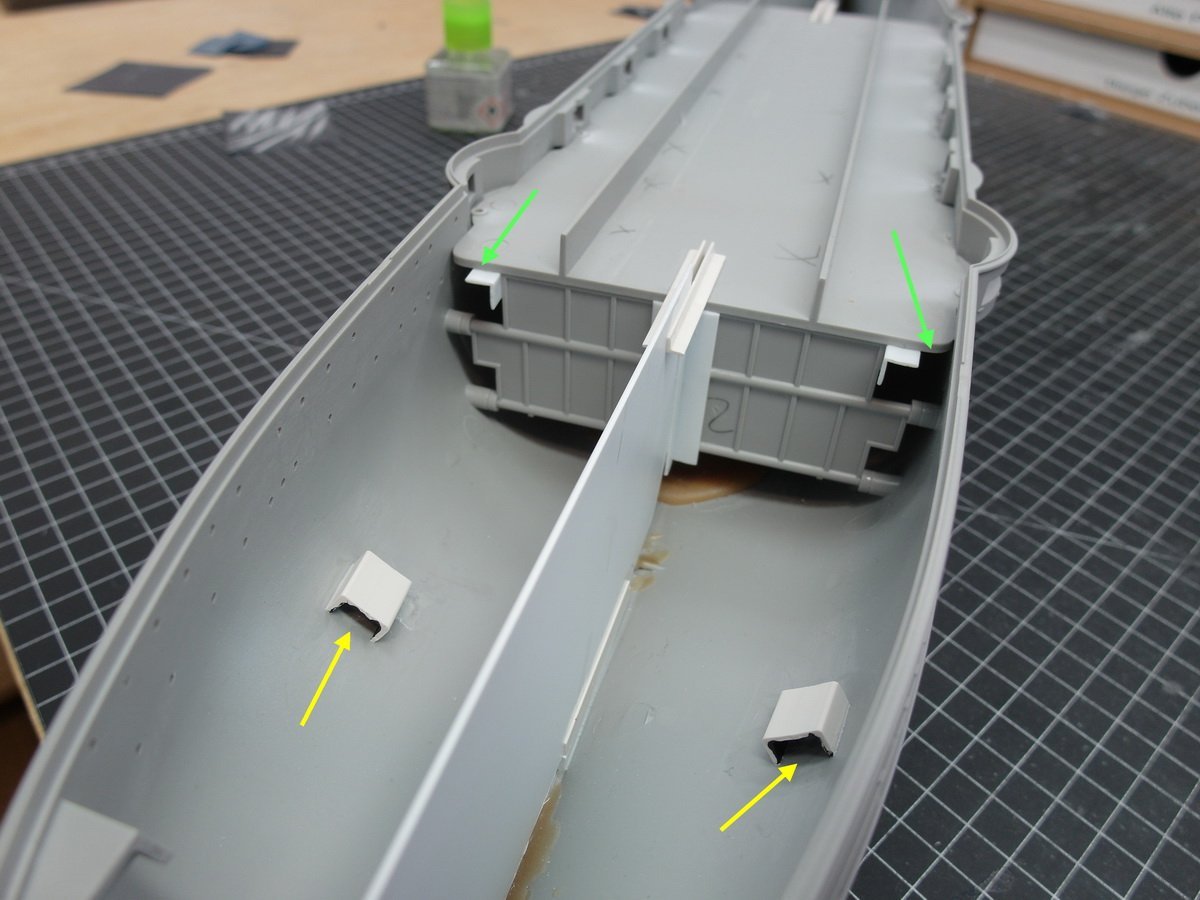
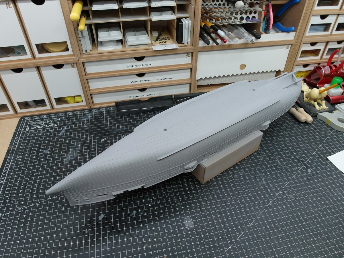
Thank you Yves. Then let us make more details in the inner values of the ship. I’m going about this a little differently than usual. For me, the cannon barrels are attached to the model much later and the deck has to be closed early. There are two reasons for this. The special feature of the Mikasa is its casemates with the protruding gun barrels. They get in the way and you quickly get stuck with them as you continue building. In general, I always attach large pieces very late. I will also raise the hull to the next level earlier than usual. It’s about the upper row of casemates. If you glue this fuselage part later, which is actually logical and intended, you can get to the internal structures much better. But you also end up with a very unsightly slot that can no longer be removed. More on that in a moment. First I soldered the shields of the cannons on the bow and stern. Then, since you can’t see anything behind the shields anyway, I simply replaced the cannon body with a small piece of styrene pipe. This was then glued in… …and I’ll simply put the barrel of the cannon through the hole later. The same with the middle casemates, only here it is much less complicated. Now that all the cannons in the hull are installed, I can prepare the deck. First say goodbye to unnecessary details. I got a small electric chisel, it simplifies things a lot. After the grinding orgy, the deck was glued to the bow. And the other two parts. Great, deck ready. Let’s come to the slot mentioned at the beginning. Here you see the culprit. I might still put up with the gap at the yellow arrows. But the one with the green arrow, no, doesn’t work at all. And that’s exactly the problem. What I would then have to mask off on the wooden deck, superstructure and other details if I wanted to fill and paint the gap late was almost impossible. That’s why I’m going to say it in advance. Anyone can do it.
- 26 replies
-
- 4
-
-
-
- Russo-Japanese War
- Mikasa
- (and 2 more)
-
Thank you Mark. I'm very pleased that you think my ship is so good. The model of your Bismarck doesn't have to hide, it looks fantastic. I hope they let us participate in their further construction.
-
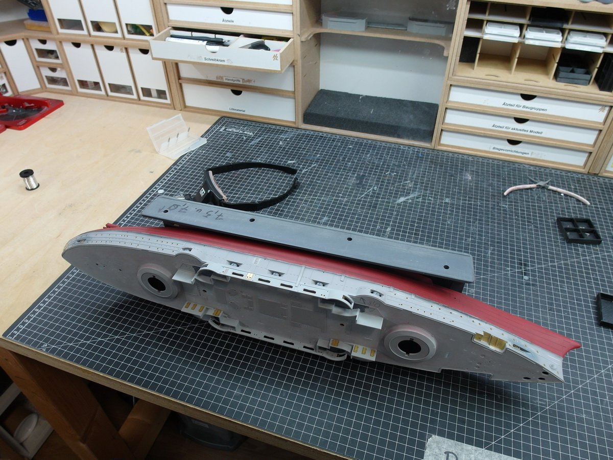
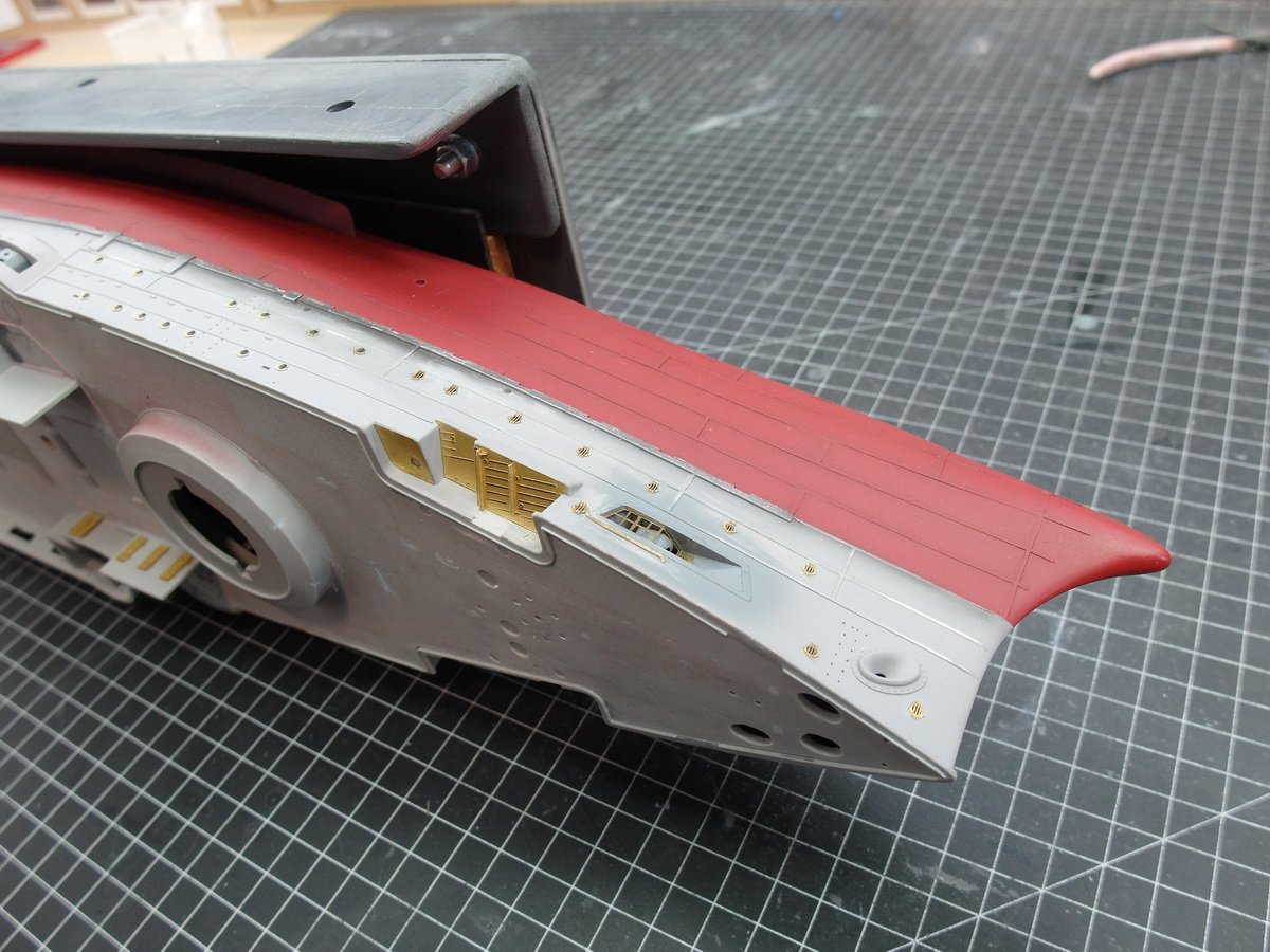
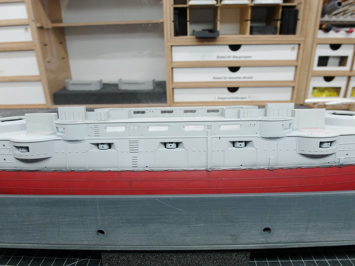
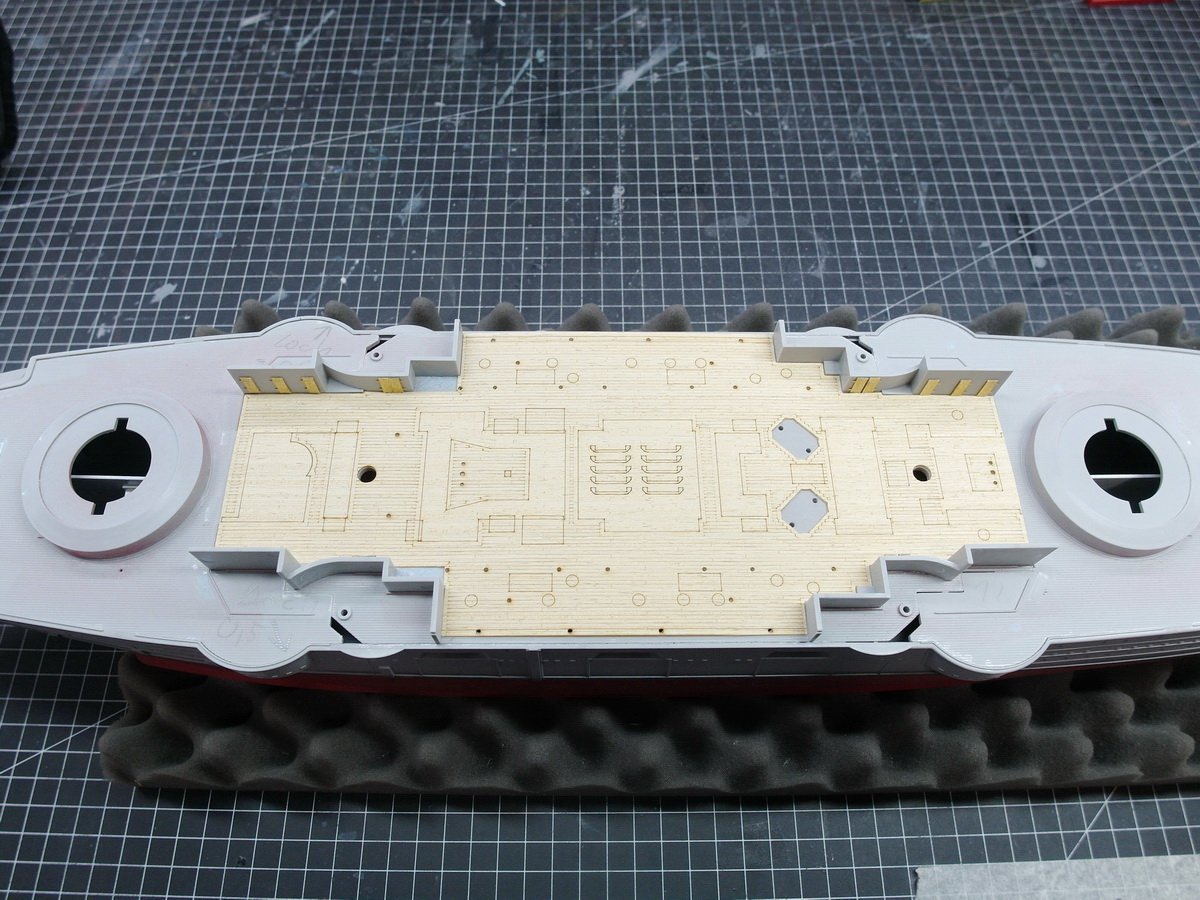
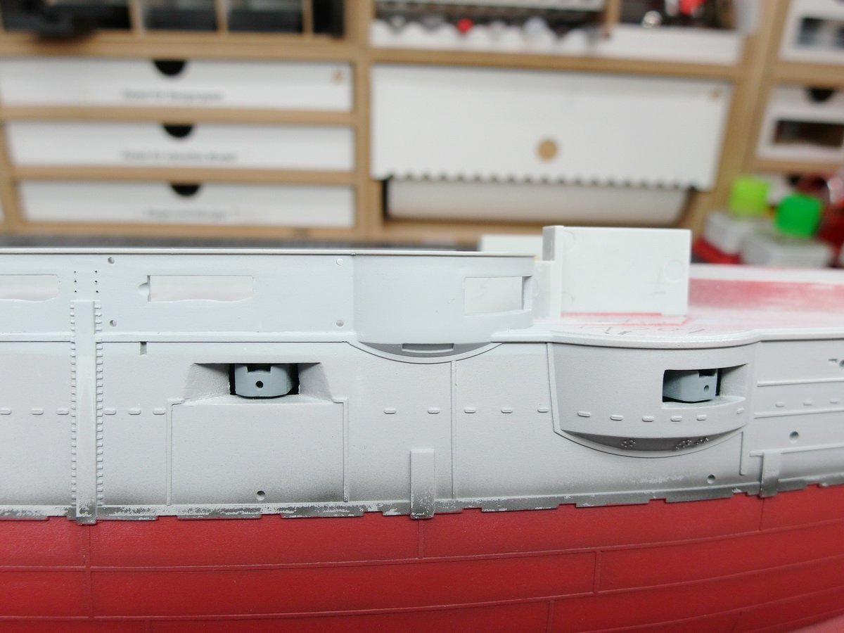
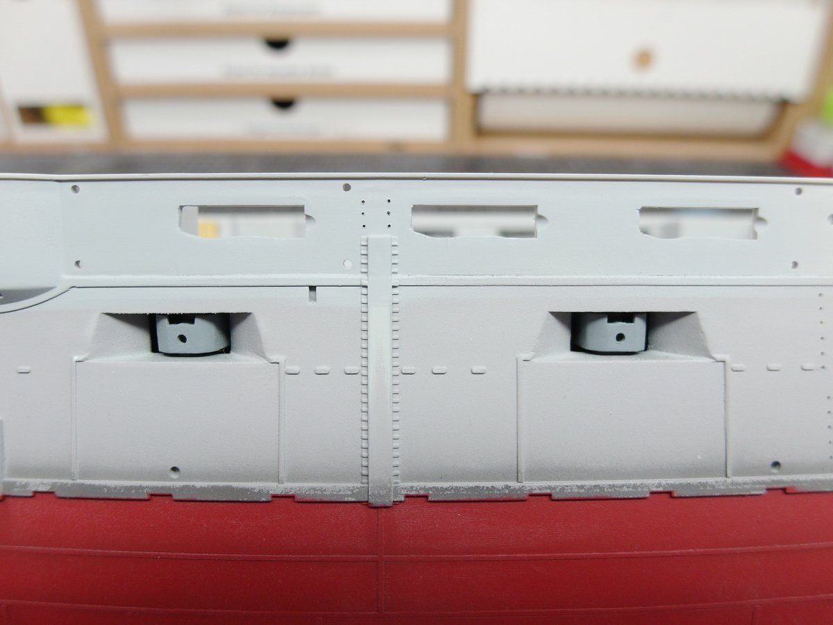
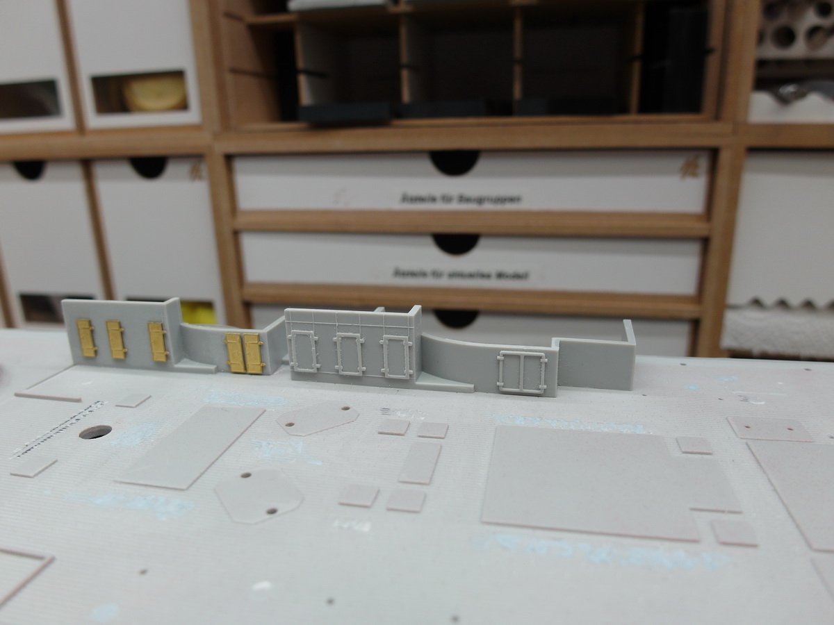
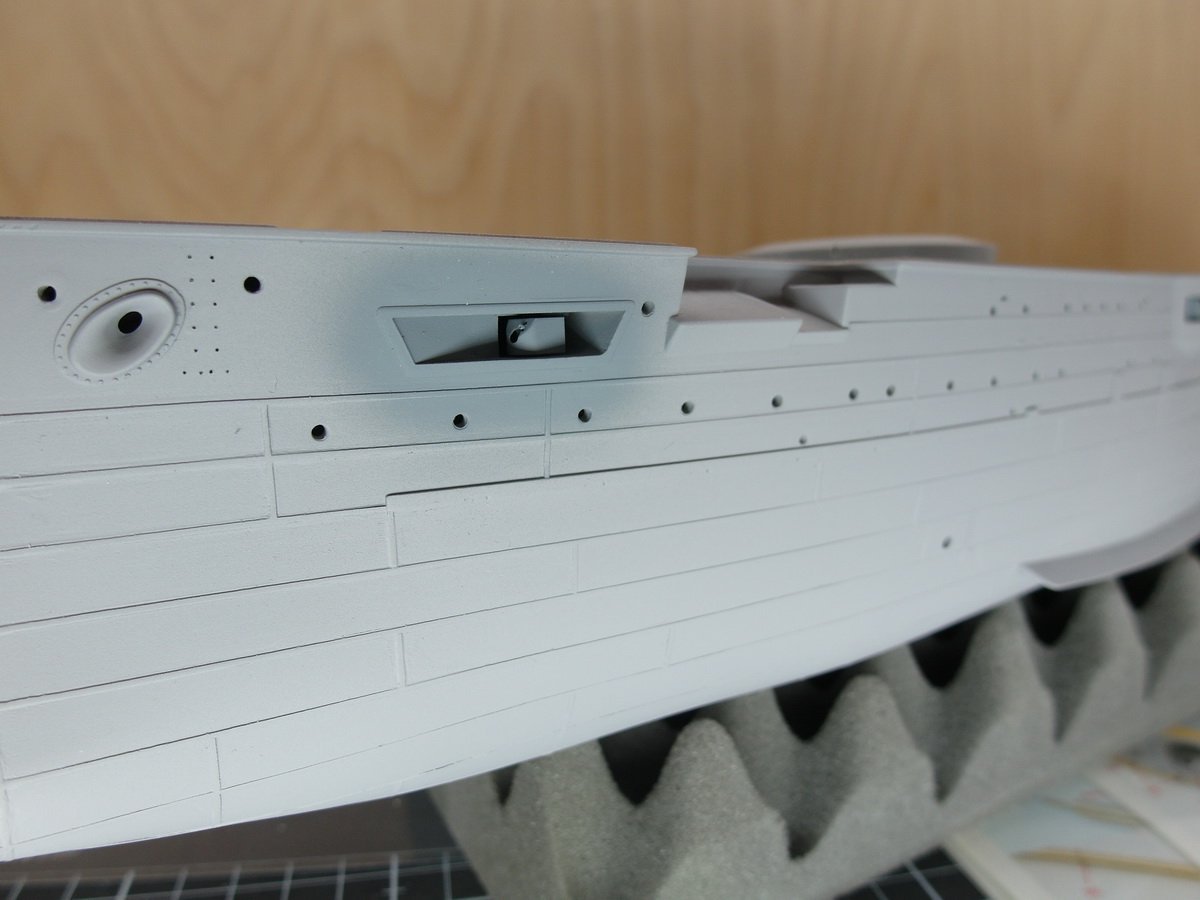
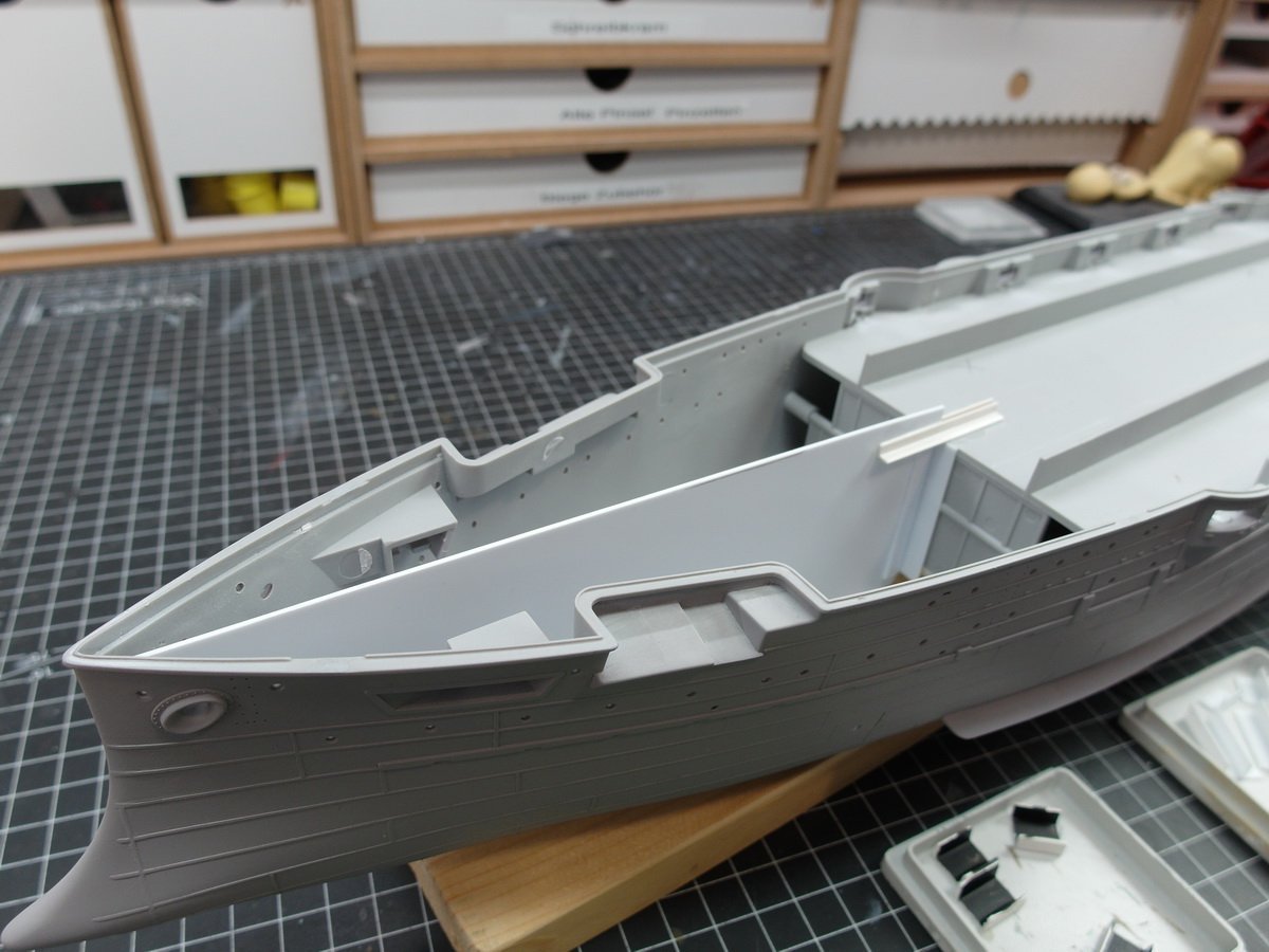
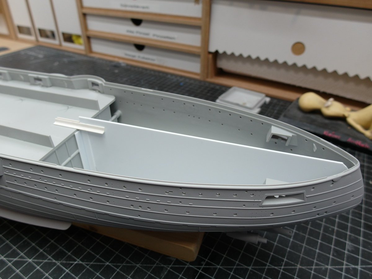
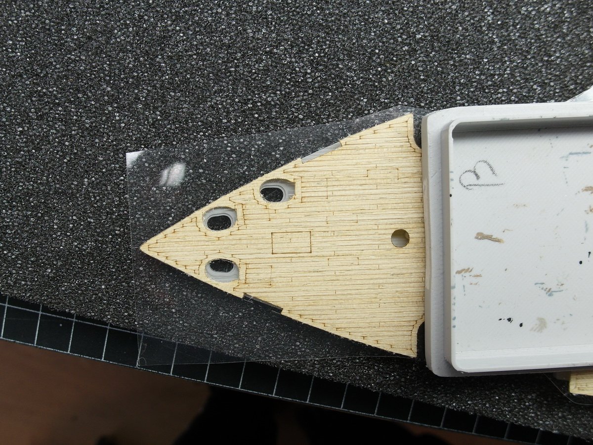
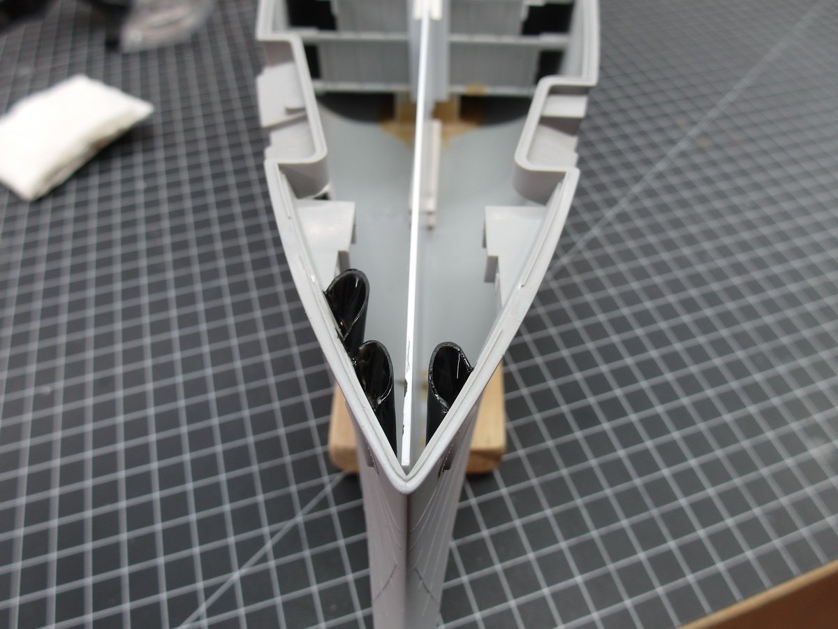
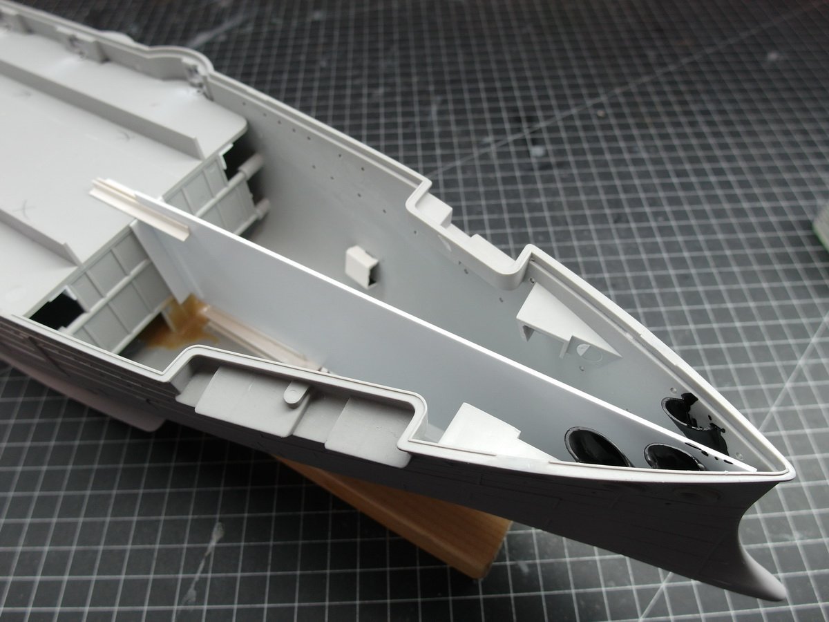
Let’s continue with the basics. A privacy screen must be created so that you cannot see the portholes from one side and the other side. That’s why styrene plates were placed in the middle. At the bow. And at the rear. The whole thing is flexible so I can move the plate back and forth a little. This is how I get the front 3 inch cannons to fit into their openings. After that I need a little individual privacy protection. One for the muzzle openings of the torpedo launchers, yellow arrows. And for four small portholes that are located under the first deck near the green arrows. It’s hard for me to get the plates right here, hence the angles. Good thing I put the Pontos wooden deck on. (Which wasn’t lasered properly and I had to help with my scalpel.) Doesn’t fit at all. I’ll have to work a little with the milling head. But it was actually about creating tubes for the anchor hawse. Now that I knew that, I created half tubes. But they are larger in diameter. Which should be completely sufficient. It’s just a matter of ensuring that no light shines through on the chain. Nice and dark. That’s the way it has to be.
- 26 replies
-
- 6
-
-
- Russo-Japanese War
- Mikasa
- (and 2 more)
-
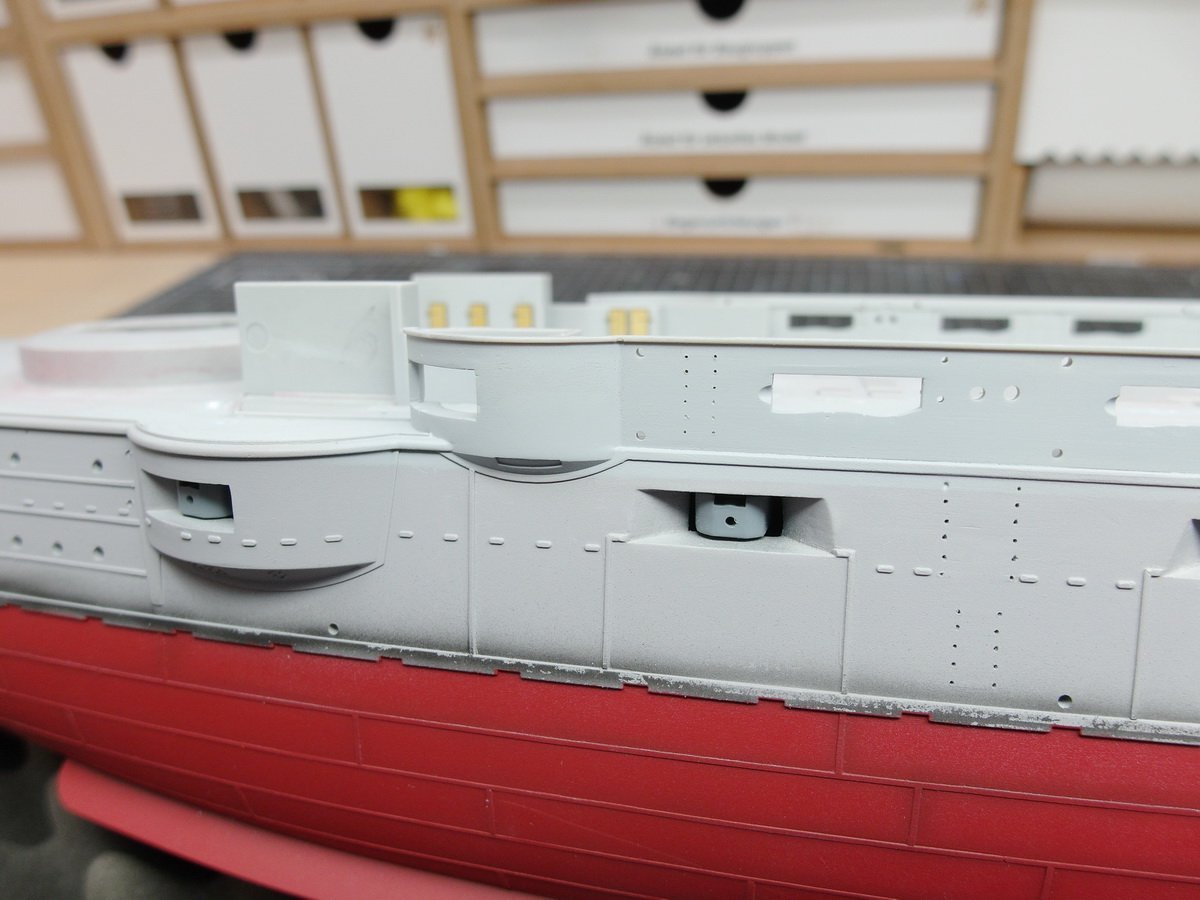
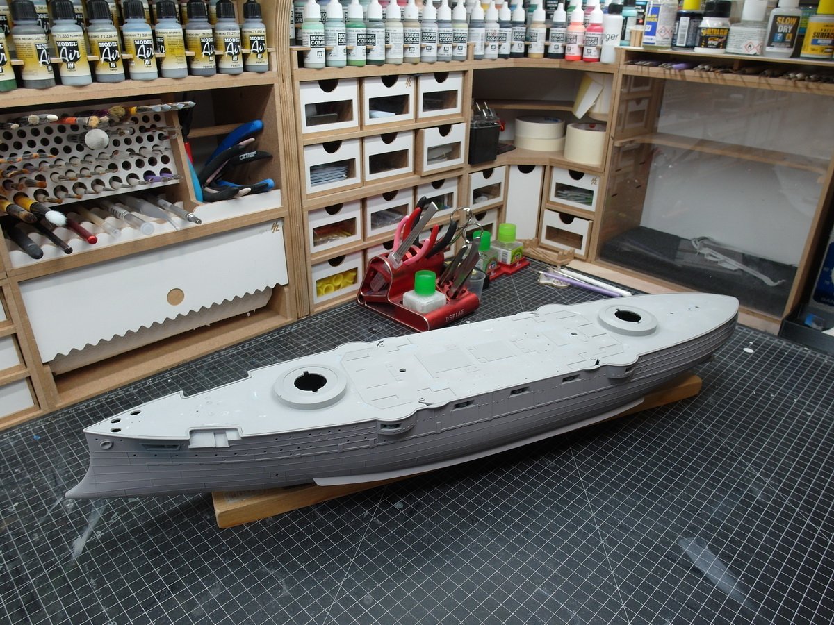
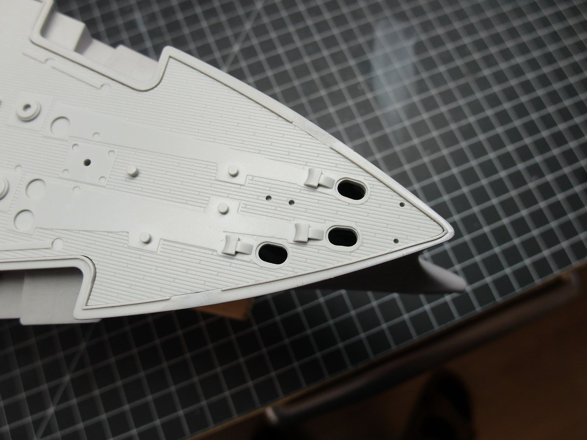
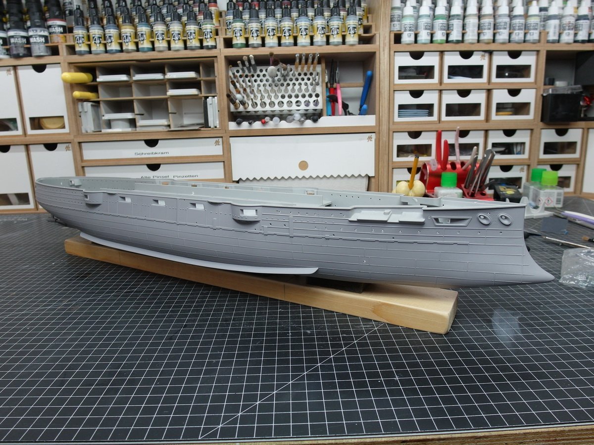
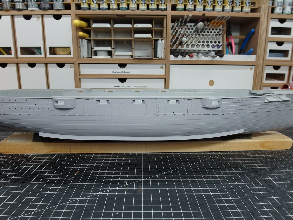
Done with the profiles. At first I wasn’t sure if I liked it because it’s actually shown the wrong way around. Because the plates would have to create a gap and not an elevation. I also sanded down the profiles on the underwater hull a lot Of course also in the places that you can hardly see afterwards. And so I think it’s going to look really good at the end.
- 26 replies
-
- 6
-
-
-
- Russo-Japanese War
- Mikasa
- (and 2 more)
