Peter Joyce
-
Posts
26 -
Joined
-
Last visited
Recent Profile Visitors
139 profile views


-
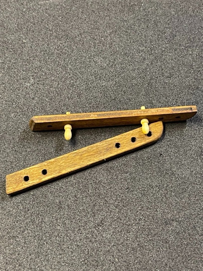
Plate 2, Part 14: Belaying Pin Rack Another easy one -- this one is "cut out form laser cut sheet and glue to board." I considered fabricating these but didn't have the wood on hand. I opted to stain these as they looked a bit plain. These are then mounted to the stern. I needed to do a bit of filing and sanding to match the angle of the transom, but other than that, it was just a matter of gluing them on. I opted to make and mouth the midship set as well. listed as part 17. I hope nobody turns me in for cheating.
-
 GrandpaPhil reacted to a post in a topic:
Lynx by Peter Joyce - Panart - 1:62 - Baltimore Schooner
GrandpaPhil reacted to a post in a topic:
Lynx by Peter Joyce - Panart - 1:62 - Baltimore Schooner
-
GrandpaPhil reacted to a post in a topic:
Lynx by Peter Joyce - Panart - 1:62 - Baltimore Schooner
-
GrandpaPhil reacted to a post in a topic:
Lynx by Peter Joyce - Panart - 1:62 - Baltimore Schooner
-
GrandpaPhil reacted to a post in a topic:
Lynx by Peter Joyce - Panart - 1:62 - Baltimore Schooner
-
GrandpaPhil reacted to a post in a topic:
Lynx by Peter Joyce - Panart - 1:62 - Baltimore Schooner
-
GrandpaPhil reacted to a post in a topic:
Lynx by Peter Joyce - Panart - 1:62 - Baltimore Schooner
-
GrandpaPhil reacted to a post in a topic:
Lynx by Peter Joyce - Panart - 1:62 - Baltimore Schooner
-
GrandpaPhil reacted to a post in a topic:
Lynx by Peter Joyce - Panart - 1:62 - Baltimore Schooner
-
GrandpaPhil reacted to a post in a topic:
Lynx by Peter Joyce - Panart - 1:62 - Baltimore Schooner
-
GrandpaPhil reacted to a post in a topic:
Lynx by Peter Joyce - Panart - 1:62 - Baltimore Schooner
-
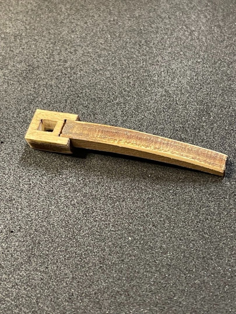
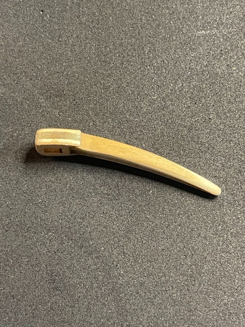
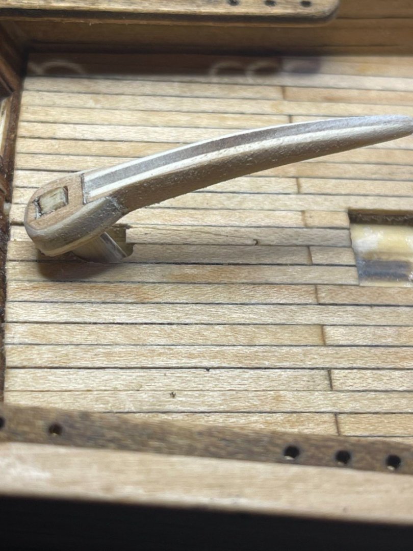
Plate 2, part 13: Tiller (Stock) Again straightforward, though differs from the instructions. The instruction say to shape from 7 x5 x50 Beechwood plank, but the pieces are included in the 5mm Laser-cut sheet. There are two parts, a swept part and the hole for the attachment. Putting one in the other gives you the rough tiller shape: This is then glued and sanded down to the correct shape. And finally, mounted to the top of the recently placed rudder, I will end up painting this. In this case I don't like the raw wood look of the plywood, so likely painting it brown.
- 25 replies
-
- 1
-
-
- Baltimoe Clipper
- baltimore schooner
- (and 2 more)
-
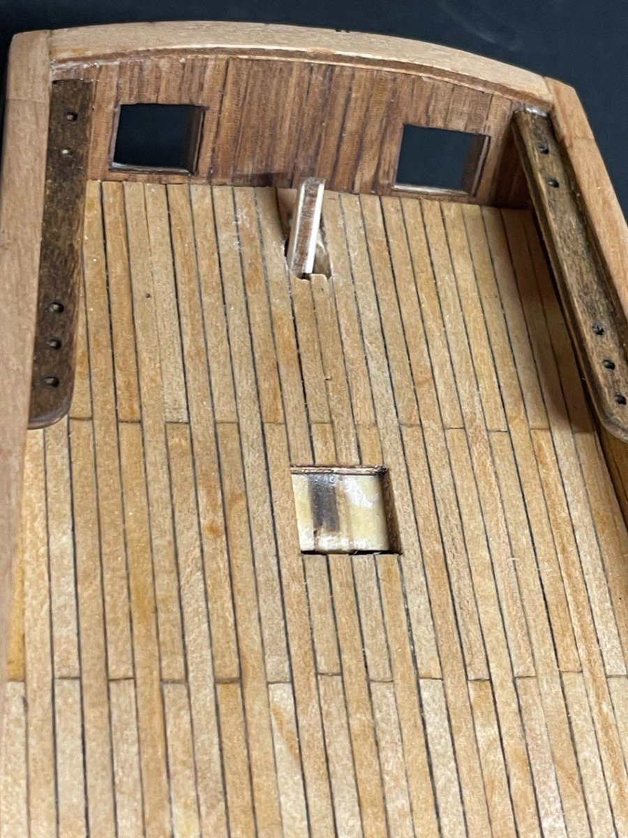
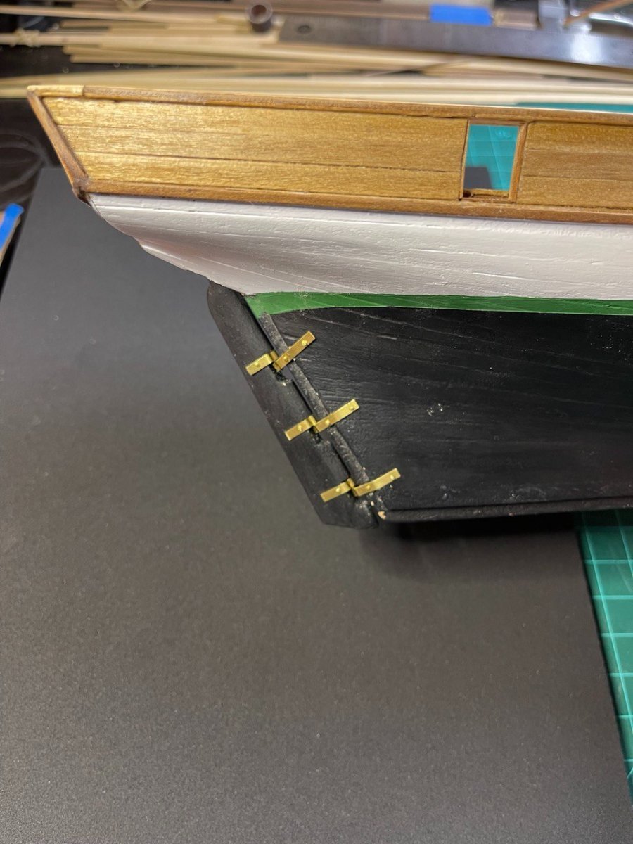
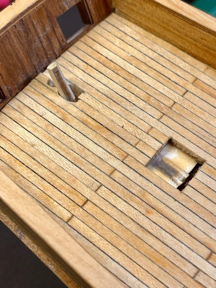
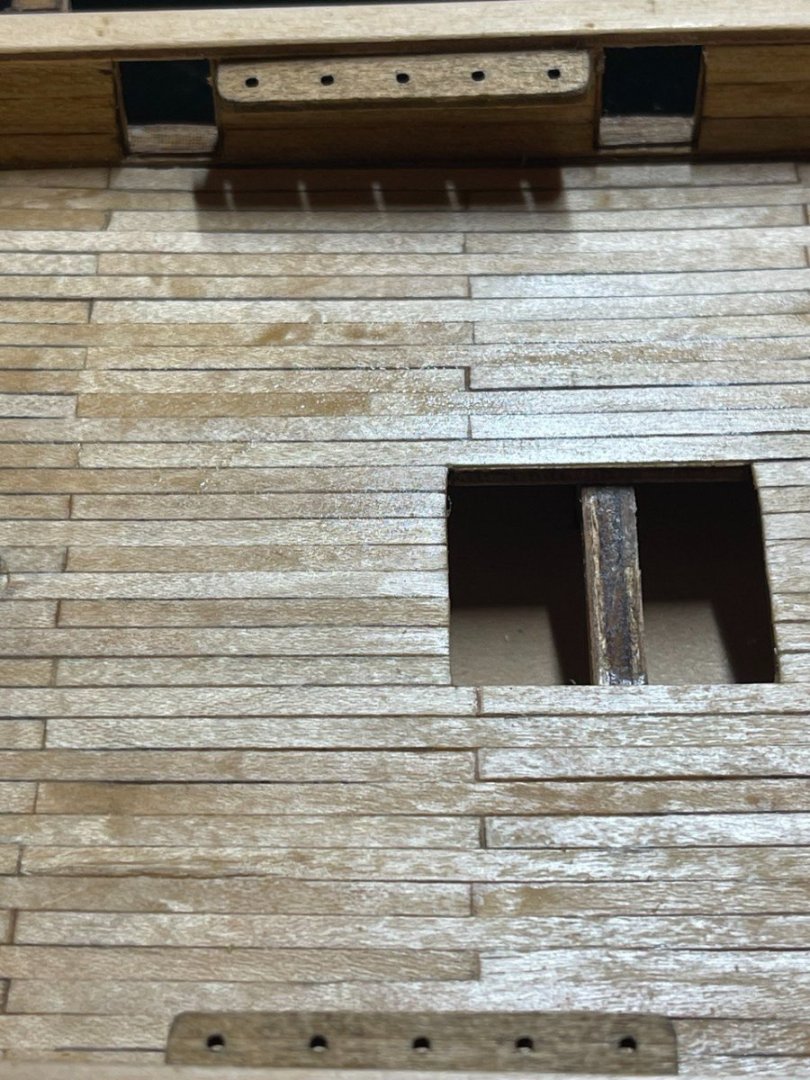
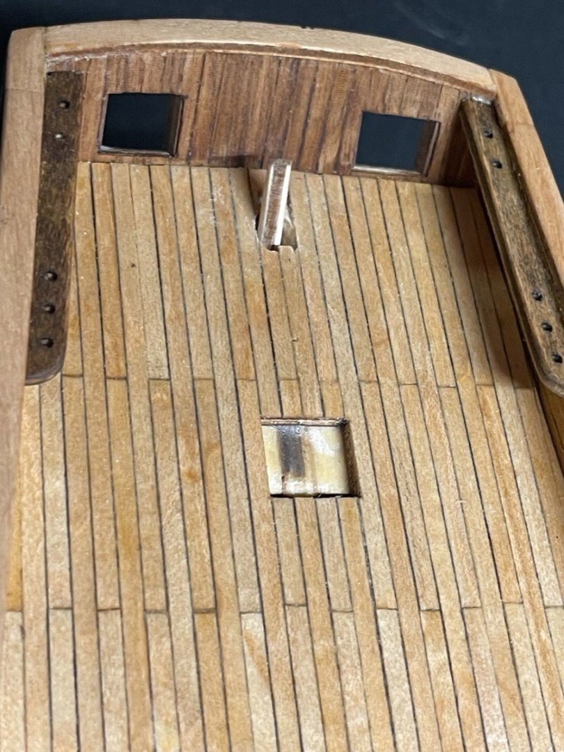
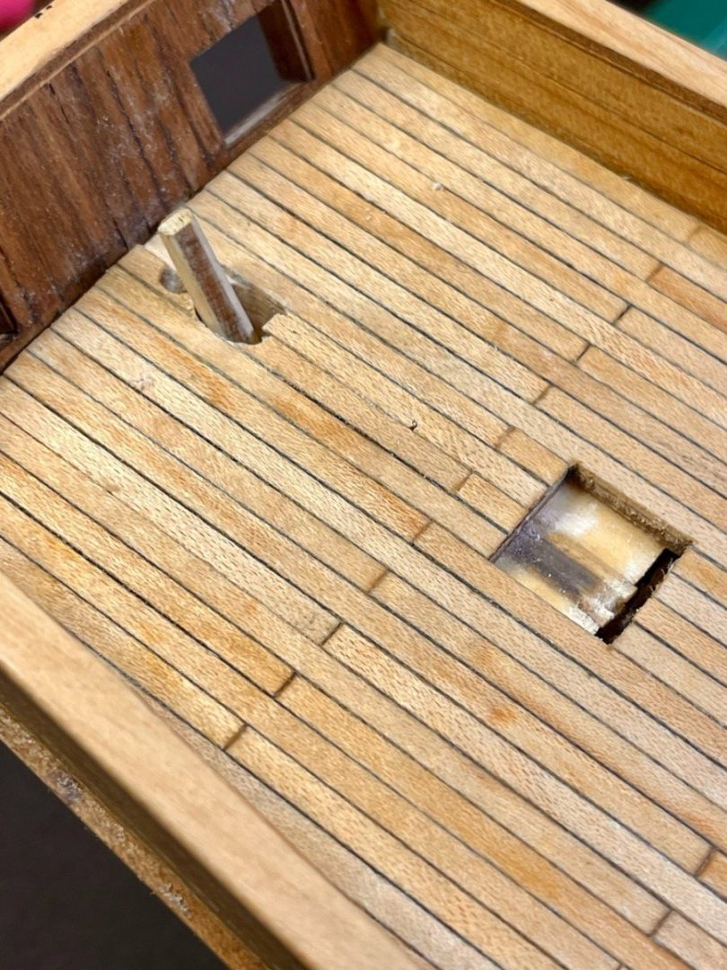
Plate 2, Part 12: Rudder The rudder was fairly straightforward. It is included on the 5mm laser-cut sheet and must be shaped to have a rounded edge to allow for rotation. It took me a minute to realize that I had to drill/carve a hole to allow the tiller portion to extrude through the deck. I had assumed the rudder would be decorative only and the tiller would just be adhered to the deck, but when trying to figure out how it went on I figured out that the top part attached to the tiller. To do this, I laid the rudder/tiller on the stem and marked the middle, then used a pin vice to drill a hole up to 1/8". It was a bit too tight to get a good angle and my first hole was a bit off, which I'll have to fix on the deck. To get the right angle and size, I filed out the hole until everything fit and there was some range of motion. This is where experience comes it, I had taken great care to shape and paint the planks which I ended up basically filing away. Unfortunately no picture of the process. The instructions say to affix the rudder braces with the pins inserted, but I found no pin. Instead, I used 1mm brass rod and drilled a hole. Because of the angle of he pin-vise I had to insert the rod and then bend it straight, which wasn't difficult with the soft brass. I then affixed the braces to the rudder by drilling holes and inserting brass brads. I repeated that process with the ones attached to the hull, with a bit of finagling. I was at about a 60% decision to remove and re-place the top bracket to align it with the others, not sure what happened there. Now looking at the picture, I think that has increased to 100% chance. The below shows the portion of the rudder on the deck to which the tiller will attach. I will need to put something around it to neaten it up and cover the hole, I believe a circle of wood is the traditional thing to put there, so I will likely cut a dowel and drill out the center, then file and sand to shape.

- 25 replies
-
- 1
-
-
- Baltimoe Clipper
- baltimore schooner
- (and 2 more)
-
Peter Joyce reacted to a post in a topic:
Perseverance 1807 by Isaiah - FINISHED - Modellers Shipyard - Colonial Brig
-
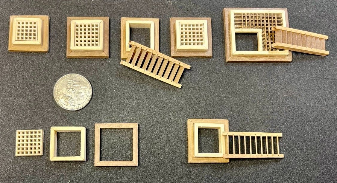
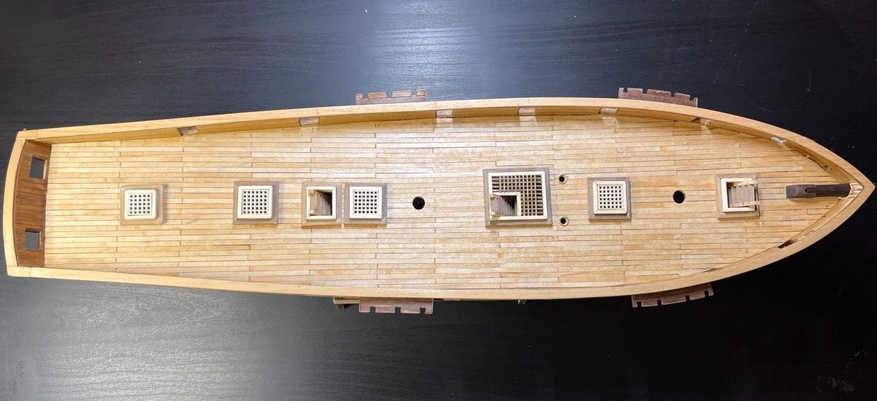
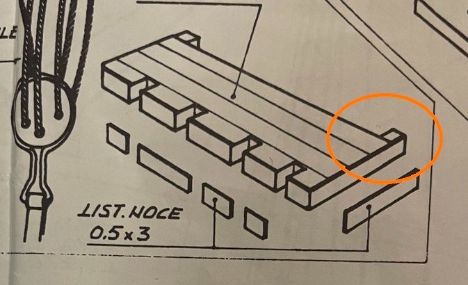
Plate2, Part 11: Grates and Ladders The instructions for this are "Follow the methods and materials (not for dimensions and geometries) which have already been explained in Part 9." So basically "Build the grates and ladders." Because I am insane I opted to miter the joins on part 9. To be consistent I had to miter the rest of the grate openings and surrounding trim. For the grates themselves I had ordered additional grates, but it wasn't exactly the size that came with the kit, so I ended up just using the kit ones. As PChem noted in his build, the materials were tight and I needed to use some scrap from the big central grate in #9 to complete the grates. I had initially planned to trim them down and have the last "Grate" portion abut the frame, but after making the central grate it didn't look finished enough for me. So my process ended up being: Build grate to closest size of opening, ensuring it made an enclosed square of grating Miter cut the 2x5mm wood to fit the grate Miter cut the external walnut ring to fit that. Sounds like much less work when I put it like that. But there are 4 more grates and two more ladders openings so it took a bit of careful detail work. In addition, I had to construct the ladders and as noted again by PChem, I will have to trim those. I used 0.4x4mm walnut that did NOT come with the kit. The instructions specify 0.5x3mm walnut but I found I did not have enough. Below is the result with an appropriate quarter for scale. I have not yet glued anything together except the center one and the ladders. This is because I am still trying to decide if I will stain the grates. I'm leaning towards yes, because the center one is stained and I would want them to match, but not sure how much I like that now. But I also don't have the materials to rebuild it. Below is how they look on the deck. I have put two treatments of Tung oil on the deck and rails and it will likely get a few more. Initially I intended to just use Polyurethane on the deck, but after following along here I will likely stick to Tung oil and perhaps wax. I have painted as well and will show that in a subsequent post.
- 25 replies
-
- 1
-
-
- Baltimoe Clipper
- baltimore schooner
- (and 2 more)
-
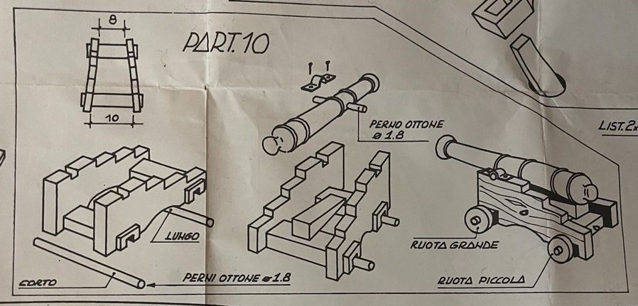
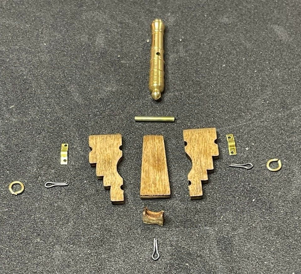
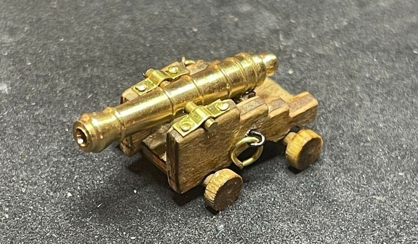
Plate 2, Part 10: Cannons I'm not sure why the instructions have this part before the rest of the grates. I suspect because that's just how the drafting was best laid out. It worked out well as I am waiting for more grating to be delivered and I'd like to see if it works a bit better than the kit-supplied grating. The parts and process for the cannons differs significantly from what the instructions say. The drawing shows two pieces of wood with axles and separate wheels as well as an elevating wedge. the kit contains pre-built wheel and axle assembly and the instruction "The big wheels must be used for the front and the smaller for the back," confused me because there are two lengths axle/wheel assembly and the longer on goes in back with the shorter in front.. I figured out they were referring to the diameter of the wheel, not the length of the axles. My first attempt was to cut scrap wood to what was shown in the plan, but while it looked OK, it just didn't have a good, finished look. I then recalled some parallelogram-shaped parts of the laser-cut 2mm sheet and measured. There were 8 total and they all measured appropriately for the cannons. Scouring the plans, I didn't see where else they might be used, so I took a chance. This is likely where experience would have paid off, I imagine this is a common assembly for cannons, though looking it up didn't get me many results. I also found small pieces that I had been wondering about. I surmised that they took the place of the wedge and provided a cradle for the cannon. I did a couple of tests and dry-fit everything together and it worked. Additionally, included with the cannons were 24 (3 ea) black things that looked like cotter pins and 16 brass rings (2 ea). After doing some research, I decided are for the breech and tackle lines, with the brass rings attached for the breech lines. it remains to be seen if I will rig the lines to the carriages, there's no hardware I can find in the kit for that, I may have to order it. So the pieces for a single gun are below as best I could figure: To mount the brackets, I drilled pilot holes for my nails and then pushed the nail in the rest of the way. The same for the pins for the breech lines, which get misshapen very easily, so I had to take care. For assembly, I first stained all the pieces, then mounted the brackets. I glued the bottom to one side of the carriage just above the cutouts for the axels and then put in the pin and mounted the cannon. I then applied glue to the edge of the bottom and slid the side of the carriage into place. This allowed me to align the cannon properly. Building it first and then mounting the cannon, while it makes sense, wasn't working for me and it seemed simpler to line it up as the glue dried. Below is the finished product: This plywood does not seem to take stain well. The stain tends to gray (I may need to try a second application) and the above is after adding tung oil. I may end up painting these, so any suggestions on appropriate colors would be appreciated. One interesting research item is that Lynx is described as a six-gun boat during her capture in 1813 but the kit includes 8 guns. It would be interesting to know which is correct.
- 25 replies
-
- 1
-
-
- Baltimoe Clipper
- baltimore schooner
- (and 2 more)
-
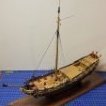
Gorgeous! I hope mine turns out 1/4 as good as this one. Thanks so much for posting this. This seems to be a not uncommon kit, but other than the one on the front of the box, this is the first completed one I've seen. I searched for pictures so that I could have a reference in the past and haven't been able to find much. Lots of folks seem to start this model but few complete it.
-
Peter Joyce reacted to a post in a topic:
Lynx by Pchem530 - FINISHED - Panart - 1:62
-
Peter Joyce reacted to a post in a topic:
Lynx by Pchem530 - FINISHED - Panart - 1:62
-
Thanks! I had test fit the ladder and the grate and saw it was too long. Good to know it isn't just me, just that reassurance helps! So it looks like I'll be cutting the ladder, thanks for the tip. I considered having it stick up above the opening, but looking at yours flush, it looks great so that's the route I'll be taking. I'm waiting until I have all the pieces constructed before I start affixing things, just so I can dry-fit and handle and oddities that come up. Thanks for posting yours so I can cheat off of your homework.
-
I'm so happy to be able to see your progress as I slough along behind you. It looks fantastic, and I have to keep stopping myself from comparing. I remind myself it's a first time for me and I will (hopefully) improve. It's great to have yours as a refence though. I love your paint, and am considering following something like your example. I have started, and was planning on following the plan's scheme of black, green waterline and white up to the fender rail. I have looked at many pictures of Baltimore Clippers and the vast majority look like yours does, with white paint between the gunnels and the fender rail. Also, a little paint and wood filler would cover a number of my sins. I don't know how I messed up the portholes still. I measured carefully, but the standoff for the chain-wales didn't fit on mine and I ended up having to trim them down. It looks OK, but yours look much better. I like what you did with the holes for the tabs, but that wasn't an option for me. Anyway, thanks again for posting all this, it looks fantastic!
-
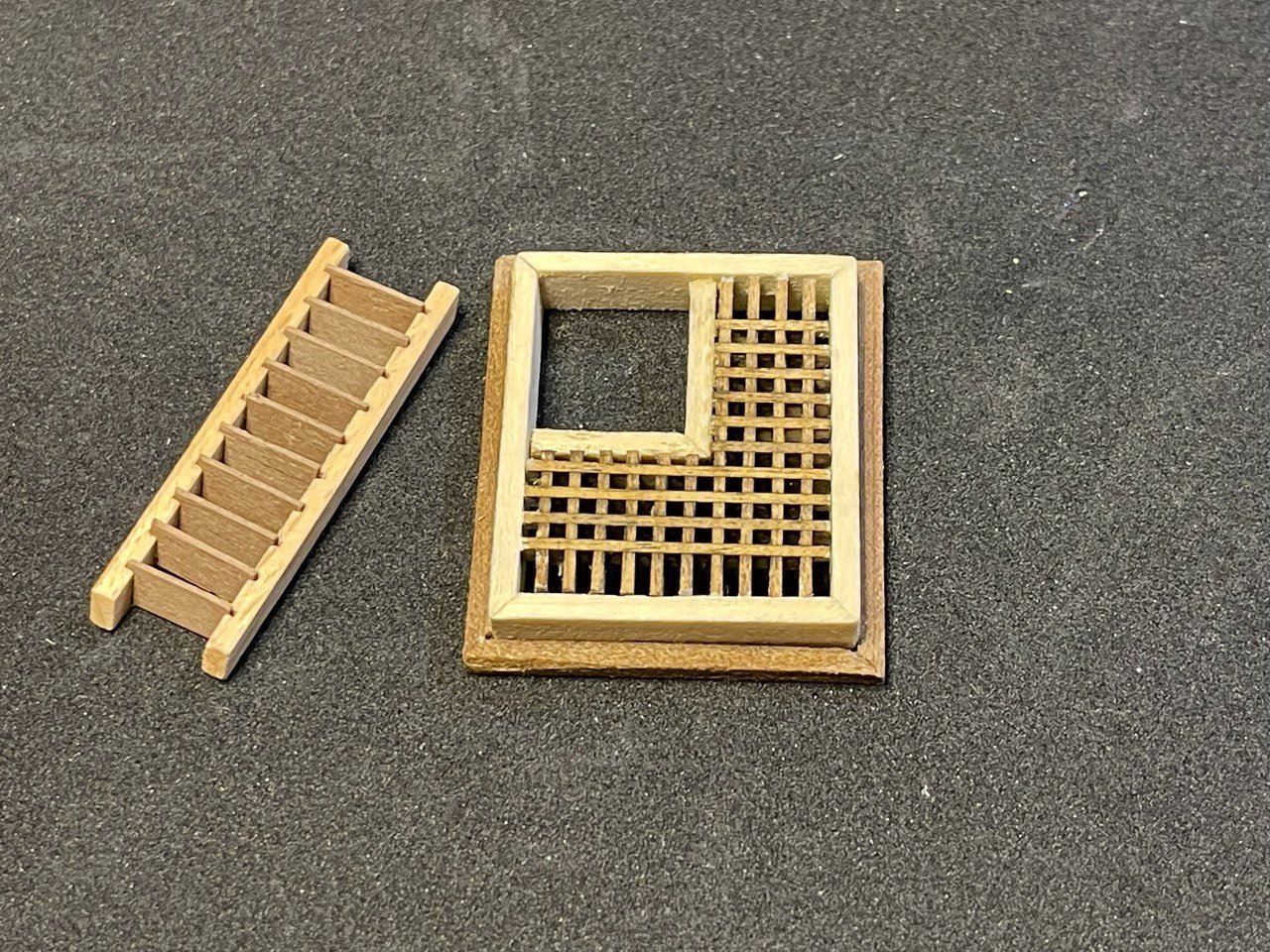
Plate 2, Part 9: Midships Grate and Ladder My first grate and it was pretty complicated. Fearing that I would run out of grating, I also pre-assembled the pieces for the other grates to figure out how many pieces would be required for each one. The instructions are very specific about the supporting frame aligning with the cutout in the deck. However, the grating supplied is not large enough to cover the opening with full grating. See below: I decided I would live with it and just have some extra on the sides. I think that was a bad idea and I should have simply moved the frame in so that the outside of the frame aligned with the inside of the opening. But being a first-time builder I opted to follow what instructions I had and build the frame to the outside. I have since ordered more grating, but that will not arrive for a week or so. At that point I will consider either knocking out the grate and re-doing it, or rebuilding it. Or leaving it alone if the new grate doesn't look right. Because I was following the specification that the frame should match the opening, I decided to build that first and match the grate to that. I then carefully measured and cut out the section for the ladder. I then put 2x2 around that opening as specified. I aligned that with the bottom of the grate as I liked the added depth and texture that gave. Though I've recently seen PChem's grate and am a bit jealous of how seamless it is, so that also may have been a bad decision. Live and learn! Finally, I stained the grate walnut as it breaks up all the blond wood. The ladder was annoying but straightforward. For this I used my purchased 0.5 x 4mm instead of the 0.5x3mm included with the kit as I am pretty sure I will run out of it and I want the ladders to match. Below is the final result of it all. In all, I'm pleased but as stated, there are some thing I would do differently. The problem is that with the extra on the side, it looks less like grating and more like lattice. I'm not sure the staining doesn't contribute to that. Oh, and one thing I'm proud of is that the ladder fits perfectly in the space provided!
- 25 replies
-
- 2
-
-
- Baltimoe Clipper
- baltimore schooner
- (and 2 more)
-
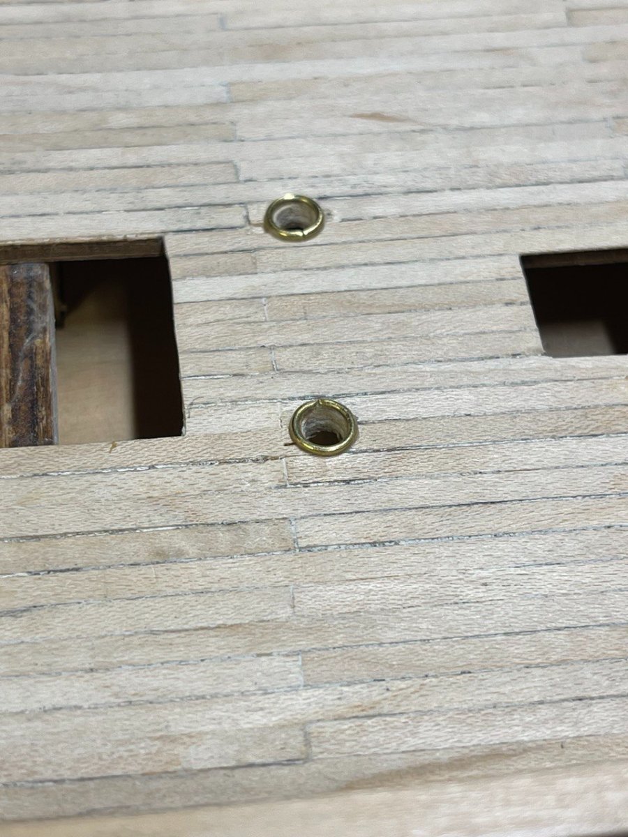
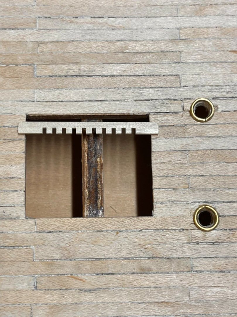
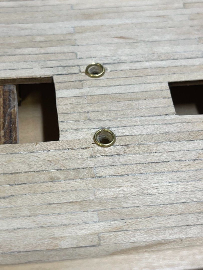
Plate 2, Part 8: Anchor Line Holes Again a simple part. This is simply two holes in the deck with brass rings around them. To find the centerline, I put the compass on either corner of a few of the openings and drew a short arc roughly at center from each side. I then lightly drew a line connecting the places where the arcs intersected and measured from center to match the plan. (I remember my old drafting classes. ) I drilled the two 4mm holes and then used a round files to file them out a bit more, the 6mm dia rings were just a touch too big. I considered filing down and removing some of the decking to inset the brass rings, but wasn't confident I could do a good job of that, so I glued them in place. When the anchors and anchor lines are attached, those will end at these holes.
- 25 replies
-
- 1
-
-
- Baltimoe Clipper
- baltimore schooner
- (and 2 more)
-
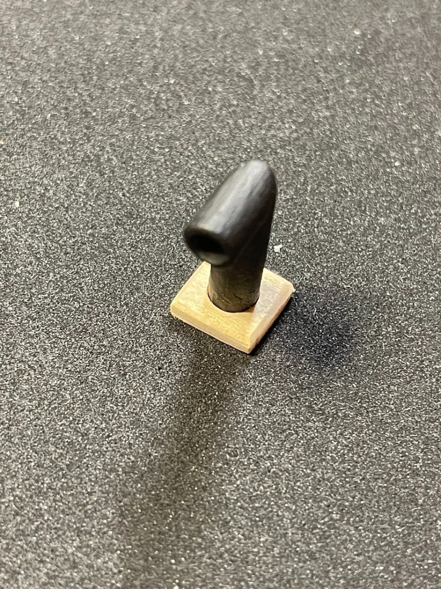
Plate 2, Part 7: Smokestack Another straightforward piece. The 6mm dowel is included in the first parts bag mentioned above in Plate 2, Part 1. I cut a 45 degree angle using the Xacto saw and miter, then flipped it. I trimmed the piece to the correct size and glued the pieces together as shown on the plan. I used (I believe) a 1/8: drill bit to drill out the center and then a circular file to carve out the inside. The base for this piece was included on the 2mm thick laser cut and was one of the ones that was cut from one of the holes in the deck. I sanded the edges of that a bit and finally painted the smokestack flat black.

- 25 replies
-
- 1
-
-
- Baltimoe Clipper
- baltimore schooner
- (and 2 more)
-
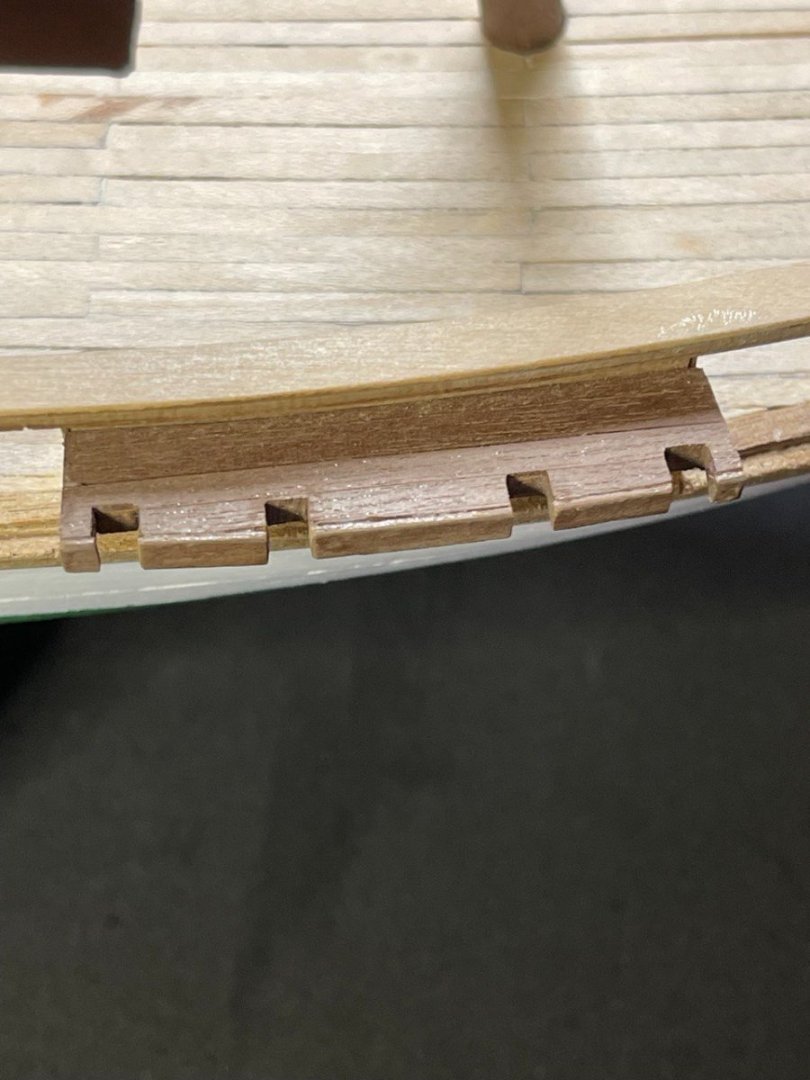
Plate 2, Part 6: Chain Wales This part had some issues and I wish I had asked here before moving on, but perhaps I can get some confirmation. The chain wales go between the second and third portholes. I cut the pieces out of the laser-cut board to find that they did not fit between the two portholes, the chain wales were bigger than the space there. I pulled out my compass and checked the plan against what I had cut out and it turned out to be exactly right. in addition, there were extended pieces on the ends that I wasn't sure what to do with. These extended about 1/2 way to the edge of each porthole, and I thought about carving out notches for them and having them stick partway into the portholes, but there was nothing on the instructions about that. So if anyone knows what I should have done, please leave a comment. Having them extend over the portholes didn't look right or good to me, so I ended up trimming off the excess on the sides of the chain wales which left only a sliver of those pieces which I trimmed off. I then planked it as shown with 0.5x3 walnut and glued directly on the hull. My theory is that the actual tension from the rigging will be on the brackets on the hull, with this just acting as a stand-off. Wish me luck! The instructions for this part also include affixing the brackets, but I am deferring that until later when the paint is finalized. Look for a follow-up for that, I've only started paining the hull.
- 25 replies
-
- 1
-
-
- Baltimoe Clipper
- baltimore schooner
- (and 2 more)
-
Thanks so much, I'll see what I can scrounge up!
-
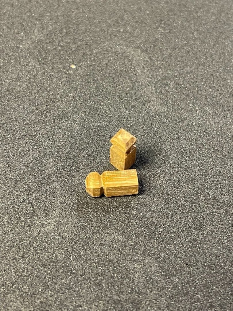
Plate 2, Part 5: Bollards Another fairly simple pair of parts. The bollards are to be cut and carved from 4x4mm Walnut. This is included in the lumber in the kit and the bollards are cut to 10mm and have chamfers/notches 1mm apart starting at the top. These are indicated on the plans. The carving was a bit difficult as they are very small pieces and I had to be careful not to carve away too much material. I used a square file at 45 degrees to cut out the notch, which worked out well. I made sure to carefully mark it so that the sides would line up properly. The instructions and diagram show that it is attached by a 1mm brass pin, however I have not found that pin so I may just end up gluing it on. I haven't put may of the deck fittings on yet, my plan is to complete the pieces and then assemble them on the deck. I want to ensure the placement is correct and I haven't messed up something that needs to be adjusted.
- 25 replies
-
- 1
-
-
- Baltimoe Clipper
- baltimore schooner
- (and 2 more)
-
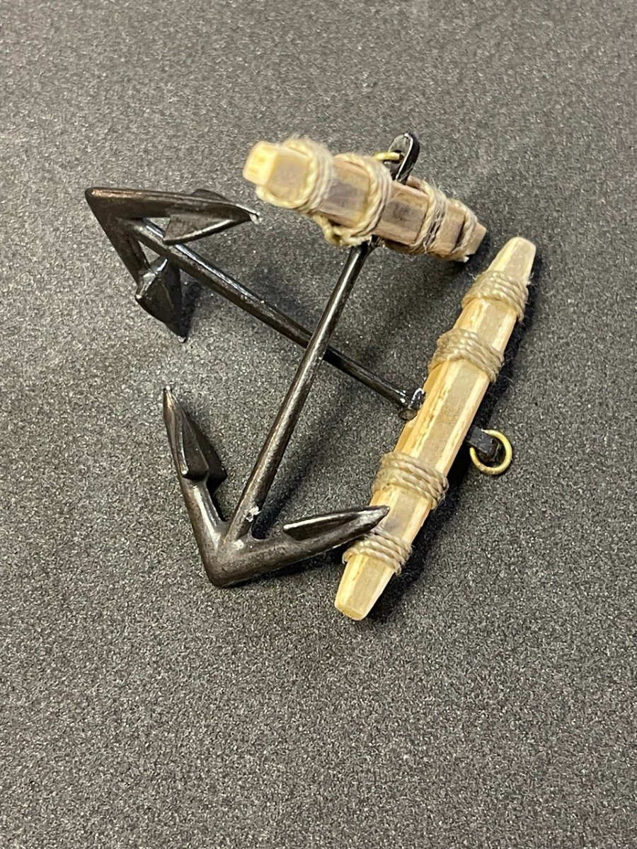
Plate 2, Part 4: Anchors The anchors are included in a separate bag containing the two anchors and two brass rings. The anchor stock is on the 5mm laser-cut board. The assembly was quite straightforward for these. I cut out the anchor stock and files/sanded to the shape indicated on plans. This entailed shaping just the top and bottom to match the angle of the two sides. I pushed the included anchor into the hole in the stock and placed the brass ring by bending it with needle-nose pliers and putting it through the hole, pretty standard. Before wrapping the lines around the stocks, I gave them a coat of clear polyurethane. After that dried, I wrapped the lines and held them in place with a drop of glue. I made sure to wrap the outside around the area where the wood from the plywood transitioned from the exterior walnut to the interior (poplar?) to make the transition look more intentional.

- 25 replies
-
- 2
-
-
- Baltimoe Clipper
- baltimore schooner
- (and 2 more)