Greg Davis
-
Posts
361 -
Joined
-
Last visited
Content Type
Profiles
Forums
Gallery
Events
Everything posted by Greg Davis
-
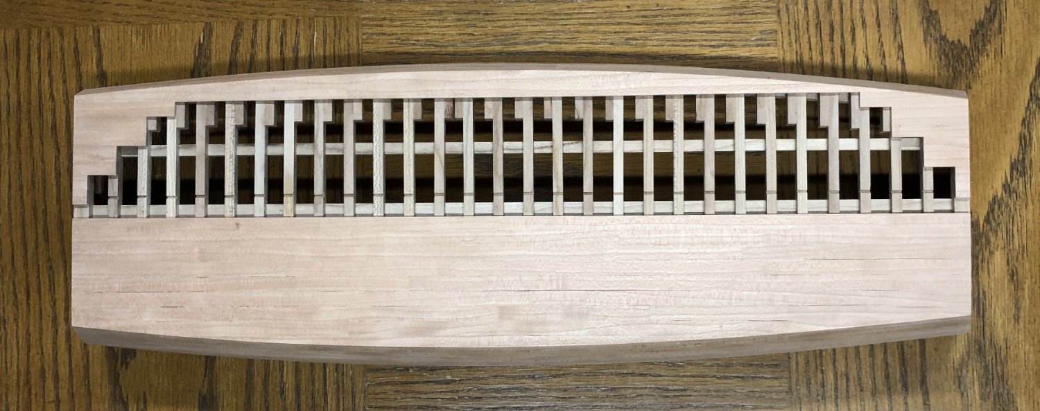
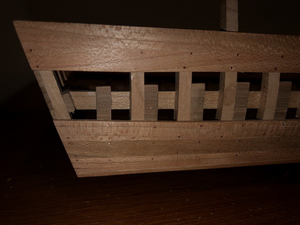
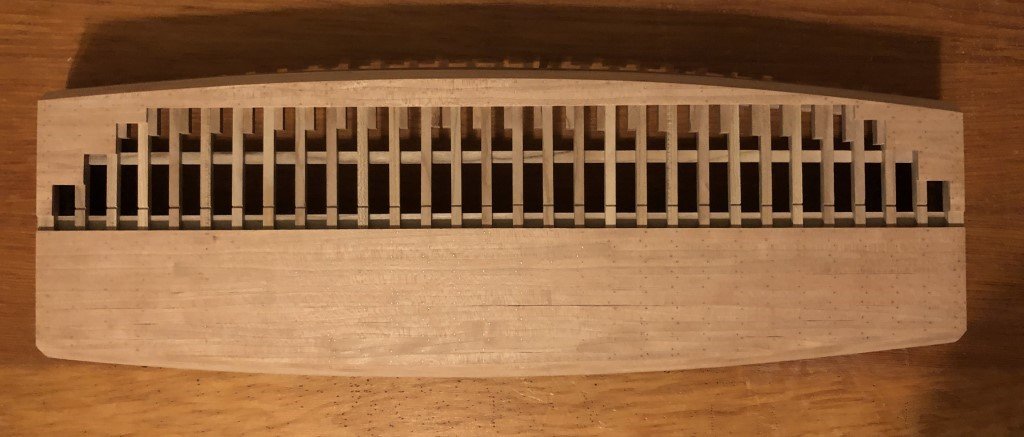
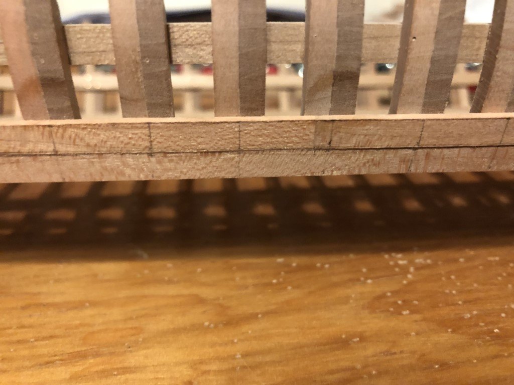
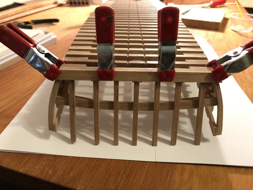
Thank you all for the well wishes! We seem to be well past the worst of it and onto the final recovery process. I wouldn't wish this on anyone. I did keep away from the power tools for quite a few days - there was a period that I didn't feel steady / in control of my movements and didn't want to be near a sharp moving blade. For that matter, I wasn't in any mood to be by a sharp knife or chisel either. Today I finished sanding the deck beams to a thickness between 2.6 and 2.7 mm. This will leave me with about 0.3 - .04 mm for final finishing once they are in place. Here's what they look like sitting close to where they belong: Now to get them all lined up proper and marked for notches that match the shear clamp.
- 199 replies
-
- 10
-

-
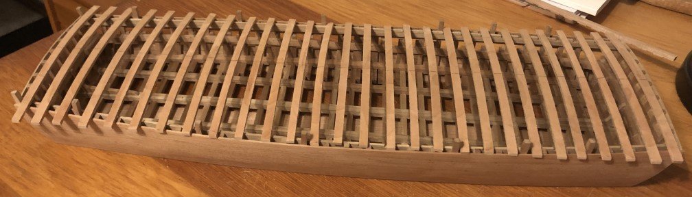
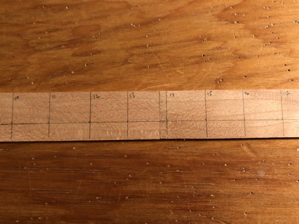
Sorry about the delay in progress, it has not been a good week or so. Even with all possible vaccines and taking care in our comings and goings, COVID finally got me (and my wife). On the up side, a new 10" bandsaw made its way to our house and I was able to set it up a couple of days ago. I tried it out by resawing some 4" material to 5/16" - it was a smooth operation. Then I used a thickness sander to bring the thickness down to a speck over 6mm for the deck beams. While not feeling well, I 'thought-created' a number of jigs and/or methods to cut out the beams. I finally settled on making a pattern for the beams that I could trace their shape with: The shape of the beam was drawn on a piece of plywood and a strip of wood was glued perpendicularly along the shape. The strip has thickness just under the 2.25mm finished beam thickness so that when a pencil is run against each side, the result is the proper thickness. There are stabilizing feet, with bits of sandpaper so the template does not move during the tracing process. Also there are two pins that I use for aligning the multiple drawings of the beams. I line the pins up on what becomes the common center line, draw the shape, and then move the template along the center line and then draw the next beam outline. In this manner, I had no difficulty drawing the outline of 15 beams stacked along a 4" axis. The beams where then cut out on my scroll saw. I am now in the process of using a spindle sander to bring the beam thicknesses to about 2.75mm. (Just 2 beams have made it to this stage.) After fitting the beams to the vessel, they can be reduced to the requisite 2.25mm.
-
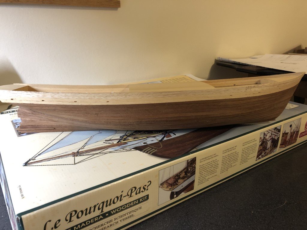
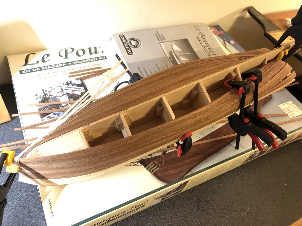
By the way, I have also done some (minimal) work on the model and it now has its stem and keel - I think that I will now get to cutting out the opening for the screw.
-
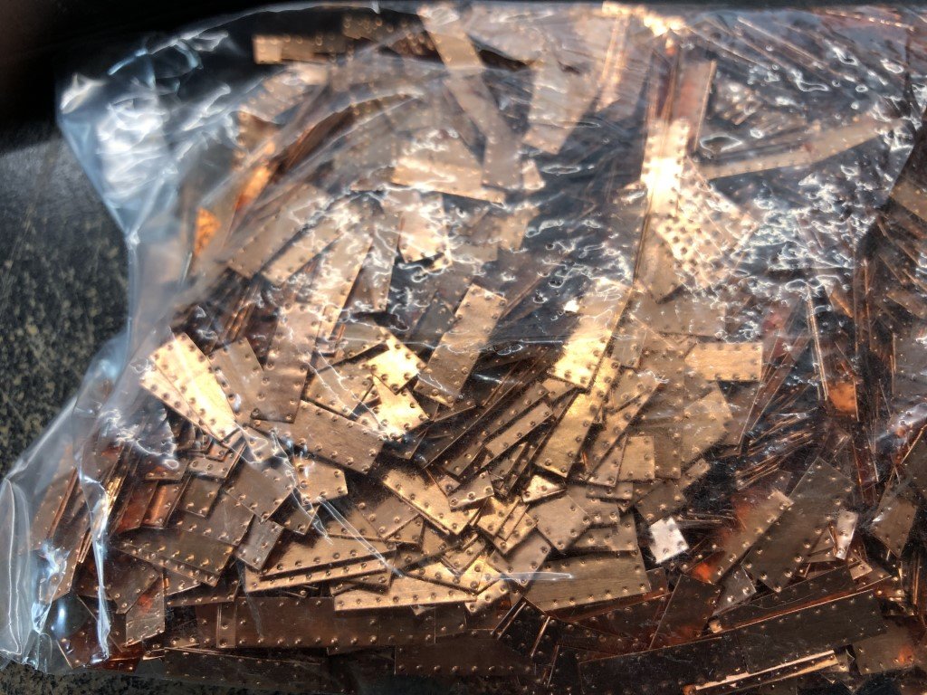
I am having no success on the size of the steel plates. I agree that in all of the pictures that I have seen, no nails are visible, so Keith, your solution seems viable. However, I was hoping to minimize the amount of paint so I am not too much in favor of painting that much of the hull - I was leaving my comfort zone by painting the upper portion of the hull white! Right now I am leaning toward copper plates without any indication of fasteners. The last week or so, I have been immersed in reading Charcot's log of Le Pourquoi-Pas? in the Antarctic. The work and risks undertaken during this time period are amazing. It is also really interesting to compare their voyage and ship to that of Shackleton's famous trip on Endurance.
-
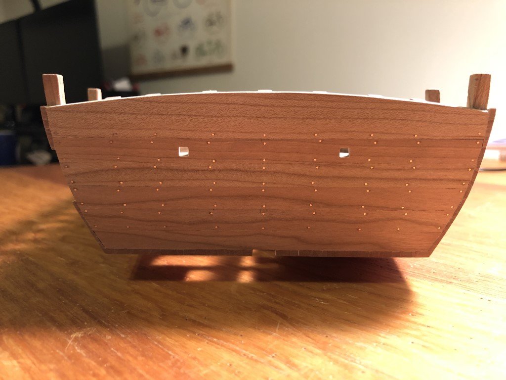
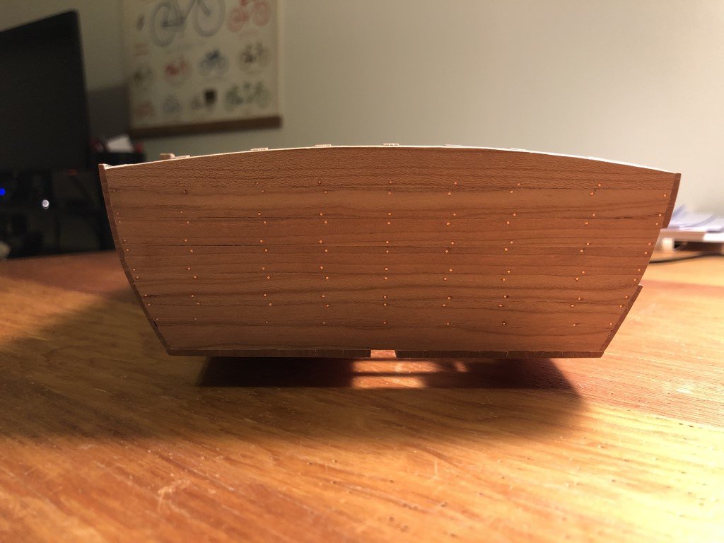
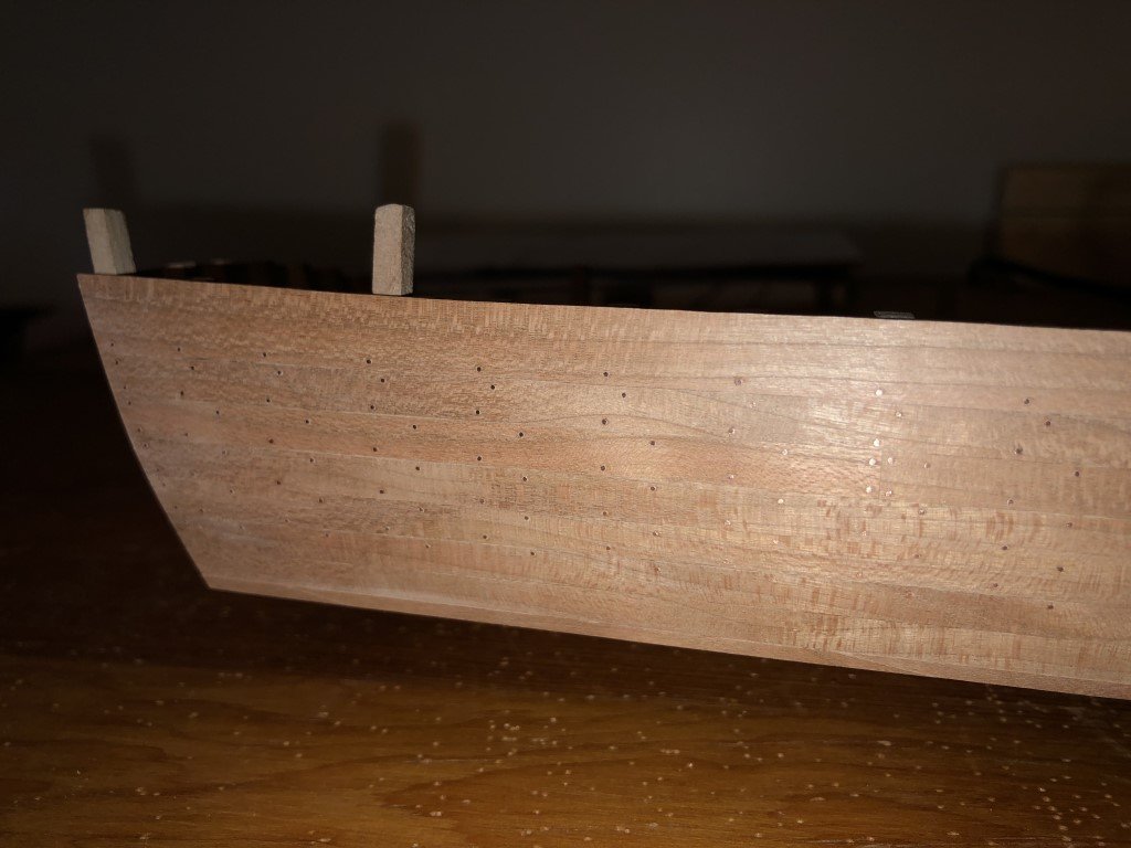
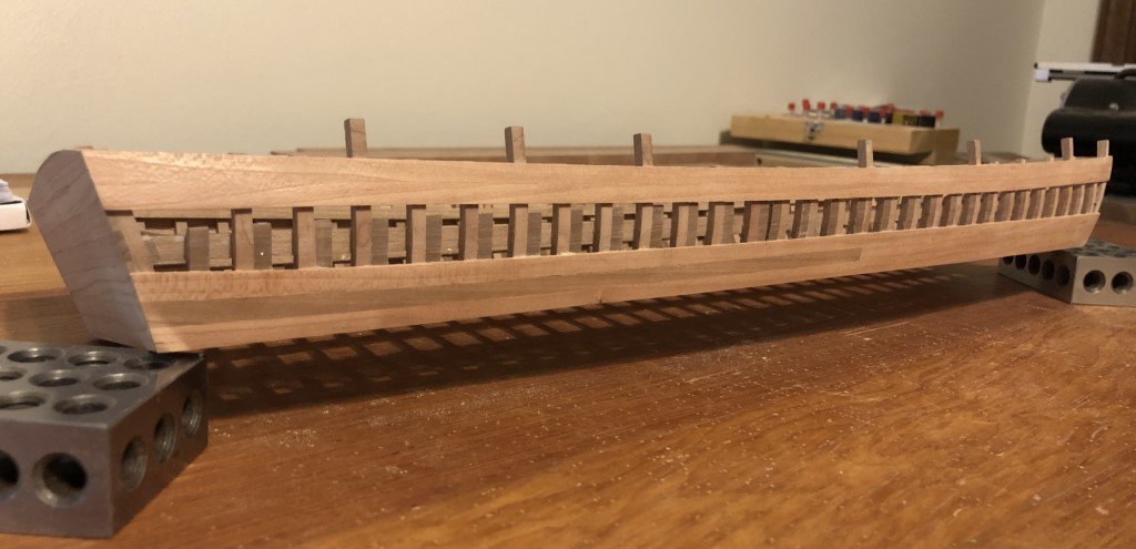
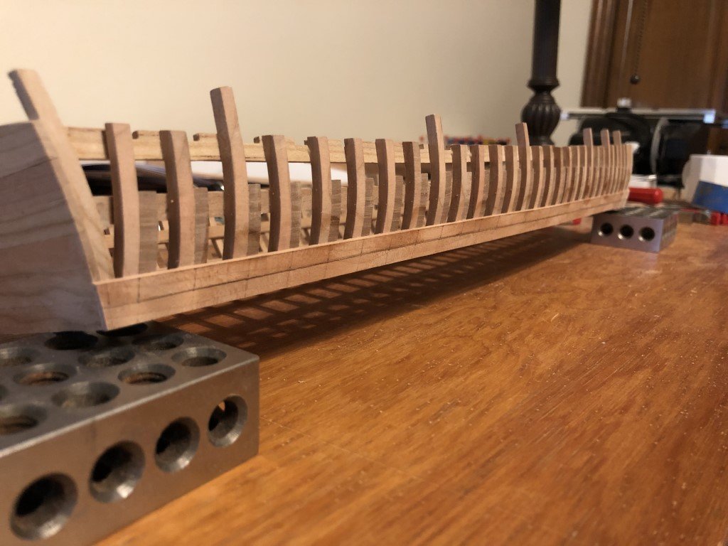
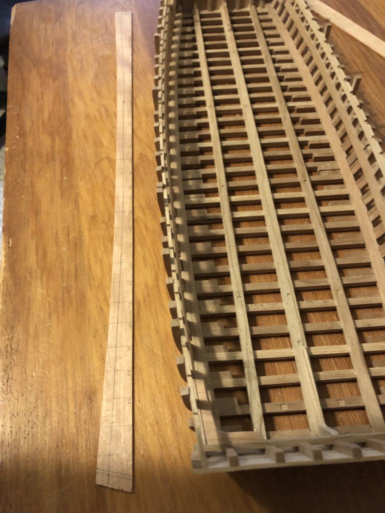
Fasteners for the first layer of planking on the bow and stern have been installed (stern lights still need to be pierced): In my last post, I thought that I would now go onto the doubled planking along the bottom of the hull. Not that this could not be done, I have had a change of heart. Before the stern and bow areas are double planked the keel would need to be installed as it is 'locked' by the doubling of planks. But without the keel the hull sits nicely on the bench and this will facilitate working on some interior and superstructure elements. I know I could get around the keel issue (and will likely need to at some point) by routing a slot into a building board to accept the keel and still let the hull sit flat. So now I think that I will set my sights on the deck beams and the uprights (that will support a pair of carlings and ultimately the wheels).
-
Installation of the fasteners on the starboard side went well. Time now to get to the fasteners for the bow and stern faces; then on to some plank doubling.
-
The drill and I did the required port side drilling successfully. As expected it was no where as time consuming as it was stressful. On the other hand, it take close to four hours to install and smooth all of the fasteners. On to the other side ...
- 199 replies
-
- 10
-
-
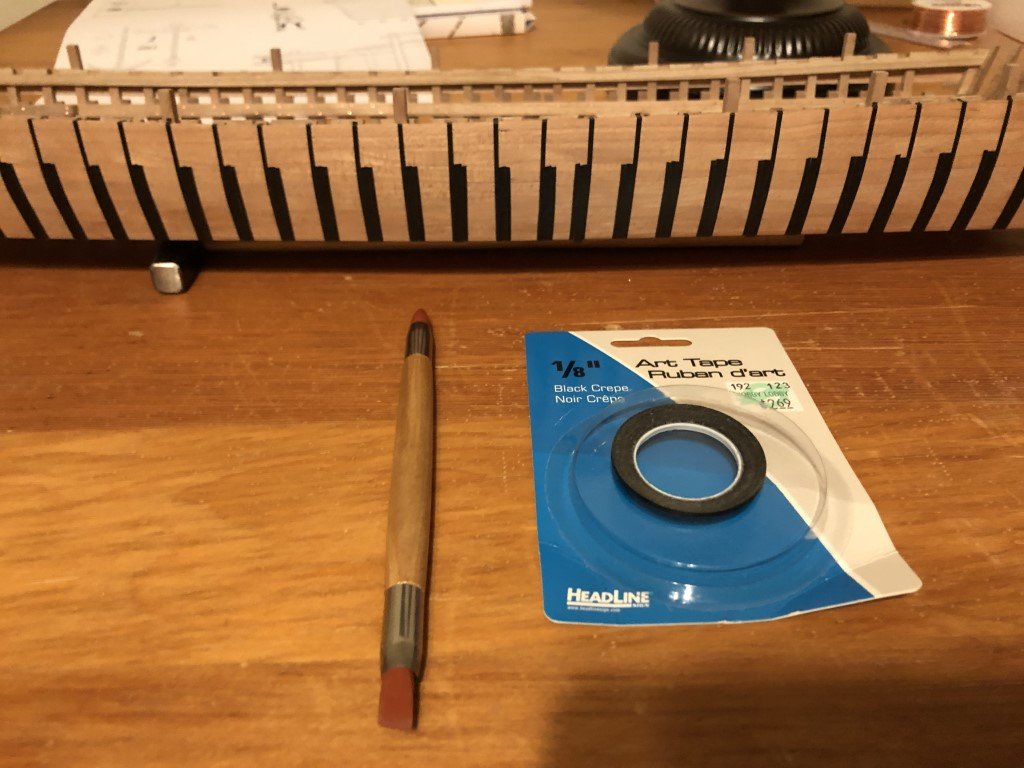
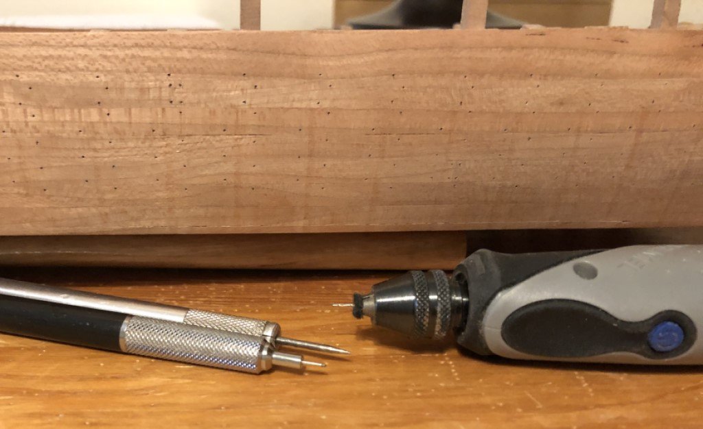
Actually, I don't mind the repetition of inserting the fasteners - drilling the holes is the part I'm not fond of. With every hole, I'm thinking drill bit please go in the right place, straight, and don't break as I just don't know how an error here will be fixed! So on that note, I'm getting ready to drill another 300+ holes into the port side of the model. Here is how I've gotten everything ready (the bottom was done this way as well). First 1/16" and 1/8" art tape was used to mask the location of frames. The tape doesn't have a great deal of stick and I found that using a rubber 'paint eraser' to bed down the tape is useful: Then, while consulting the plans a multitude of times, the fastener locations are marked on the planks just outside of the tape. I pull off the tape and check that all the pencil marks are all in the correct locations - a few more need to be put in where planks adjoin within a strake. Once all looked good, a scribe was used to create indentations for the drilling process. The holes will then be drilled with a small Dremel tool. The drill bit will be adjusted to the needed depth - about 3.5 mm here and drilling will commence tomorrow when I have the needed rest, concentration, and coffee! Also, I have placed a piece of felt on the drill bit so the chuck will not mar the planking. It was probably noticed that I did not mark fastener locations near the top and bottom of the side. I decided that I would not place fasteners in the regions that would be double planked and thus not seen. Also, there should be less chance of hitting an already installed fastener when drilling holes for fasteners of the doubled planks.
-
Just finished installing and smoothing nearly 700 fasteners on the bottom of the vessel. The copper pins should be a bit more obvious once a finish is applied to the wood. Next the four much more visible sides!
-
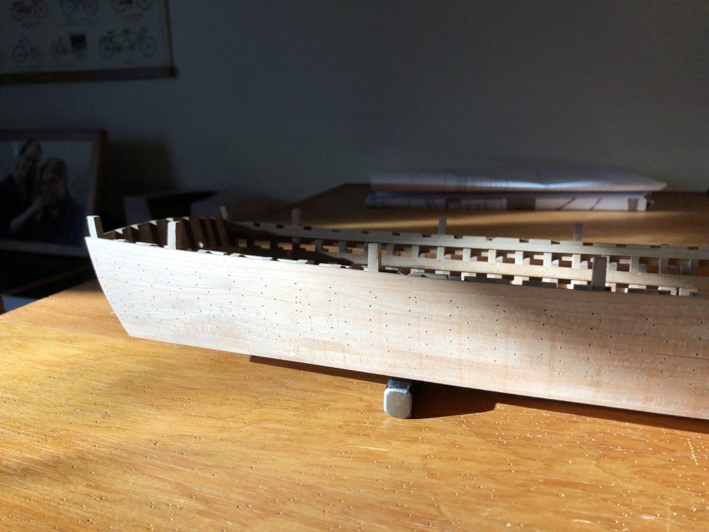
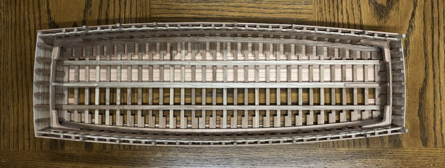
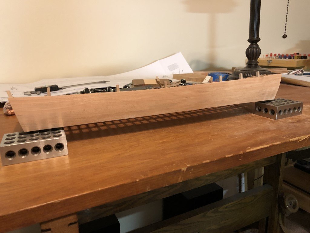
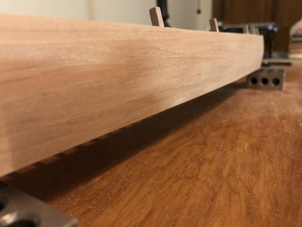
The bottom is planked and the five planked sides have all been smoothed to a state that the multitude of plank fasteners can be added. The keel is also complete, but I didn't want to put it in place until after the rest of the bottom work was completely done. In this way it will be easier to have both sides of the bottom to have the same thickness as I can use sanding blocks the span the whole width. Here is a current view from below: And a view from above: Time to get the #74 drill bit and the copper wire out - this is going to take awhile!

- 199 replies
-
- 13
-
-
I have rolls of the self adhesive copper in the correct width, but I also have plenty of copper plates with 'nails'. Not sure what will be the best choice here. In some ways, the tape may be a better (more consistent) look as there are other detail simplifications going on in this model.
-
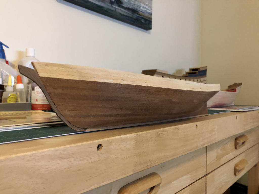
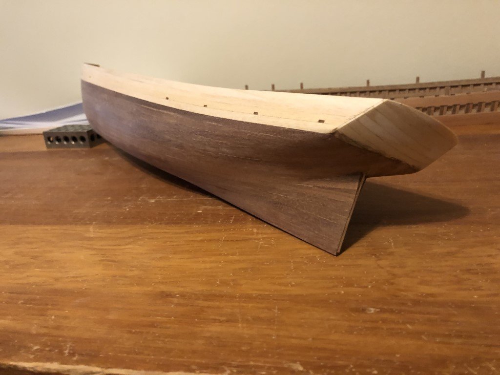
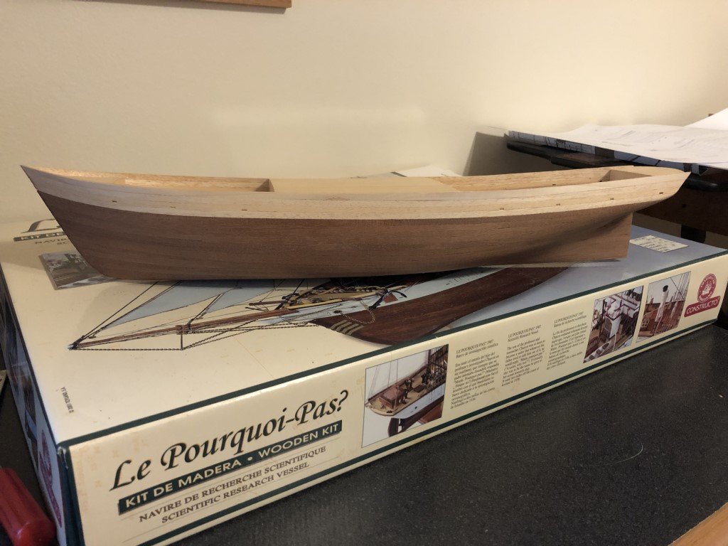
I've smoothed the hull as much as I am going to do. Spent a long time getting some nice lines by the deadwood. I also did some work on the stern. The supplied piece of plywood for the stern did not fit as nice as I would have liked, so I did a quick and dirty planking. I then filled the grain of the lighter wood with some artist modelling paste. There are a couple of rails that go along the sides that will be added after the stem is in place. I'll then prime and paint all of the lighter wood in an off-white. Next up will be fitting the stem and keel. Once the keel is in place the hole for the propeller can be opened and preparation for finishing (staining and coppering) the lower part of the hull can be made.
-
We just got hit with a cold snap over the past few days - didn't even make it up to freezing for a couple of days. But how can you complain when parts of New York State have gotten up to 6 feet of snow!
-
I just finished smoothing the starboard planking. Probably call it a day now. Tomorrow the bottom can be prepped for planking.
-
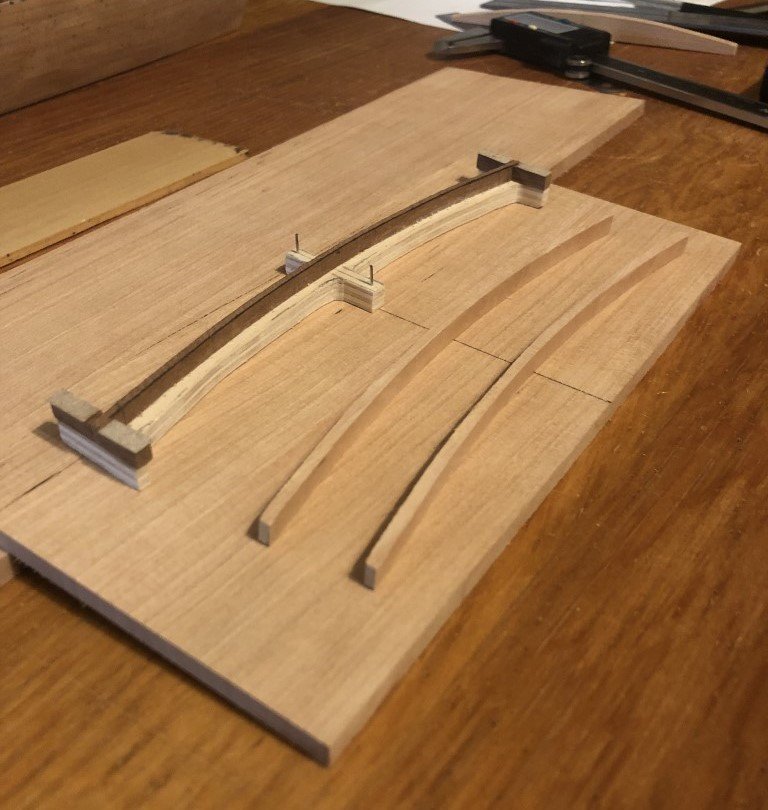
Druxy - Thank you for the input. The reason I thought to bend them is that the beams will be 6 mm wide and 2.25mm thick, the longest are to have chamber of 9mm. Because they are relatively thin with respect to the width, I thought that cutting them out of 6mm thick material would be challenging. But then I have considered making a pair of metal plates to sandwich the beam blanks and then sand / mill them to shape. This could be used to make a single beam or a longer piece that would be parted into separate beams. There are 28 beams in the vessel and they need to dovetail into the ledges, so I'm sure that I will be making 35-40 beams before I like what I need. Maybe the time spent on the making the plates would be well spent - especially to maintain consistent deck camber. Greg
-
I finished planking the port side and have given it two rounds of smoothing; first with 100 grit sandpaper and then with 150 grit. This is how it will stay until the 'bolts' are in place. At that point I will do the finish sanding as it will be more difficult to do so once the doublings have been added. Final contouring of the top edge is also on hold, until the deck beams are in place. Next, I will work on partially planking the starboard side. I know there are a couple of tasks to take care of before the deck beams, but I am trying to decide how I should construct them: cut them out individually, shape a larger piece of wood to the proper camber and then slice off the beams, or create a mould and bend strips to the correct shape. The mould method might be good practice before making the planking for the two dredger wheels ...
- 199 replies
-
- 11
-
-
Close to six hours later, the rough sanding is done and now I can move to finer grades of sandpaper. The lines of the vessel are looking nice to me already.
-
The good: all the planks are attached! The bad: at the start of October I thought I would have 4 - 6 weeks to complete the planking and then spend some time outdoors sanding the hull; 6 weeks have gone by and it looks like I missed the outdoor sanding window! Today started out warm and sunny with temps into the low 70's; now the weather is turning - its raining and the temp is to be dropping all night and into the morning when it will be very close to freezing. The 10 day forecast doesn't make it into the 40's for the high and goes into the 20's (or teens) every night. Looks like the basement beckons with dust mask and dust collector - not as much fun as I had hoped for.
-
I appreciate that! It really helps to have regular time to work on my models - these first few months of retirement have been wonderful, I hope it stays this way for a long time!
-
The lowest strake was made from one piece of wood so that I could get a nice starting position and any joints would not be seen as another layer of planks will go across this part of the vessel. Starting with the next stake (second from bottom) I will be respecting the proper location of planking butts. This particular strake is to be made from two planks joined at frame 14. I chose to join the two blanks for these planks before laying out the shape. In the following picture, the juncture is just to the left of the vertical line marking the line between the timber top and knee for frame 14. The horizontal curve is a tracing of the upper edge of the first completed strake. The tracing being done before fastening the first strake to the vessel - this simplifies the spiling process (for me). I then marked the height of the strake at each frame and drew a smooth curve through them, cut the top edge and smoothed to the final shape. Before attaching this stake to the model, it was used to mark the lower shape of the next strake on another blank. Once attached to the dredger, the plank joint looks good to me. In particular a nice smooth curve has been formed over the joint area - something that is not real easy for me to achieve when making the joining planks independently. Finally, here's a look at the lower two strakes in place - already 25% of this side done!
- 199 replies
-
- 10
-
-
I made up plenty of planking material today and have started to form the lowest plank for the port side of the vessel. First I clamped a piece of planking material to the lower part of the side and marked the contour of the bottom of the dredger on it. This shape was then cut on a scroll saw and refined with an oscillating spindle sander. Then the piece was re-clamped to the side and final adjustments to the lower edge were made to give it the correct curvature. I've measured and recorded the total height of planking along each top timber. These measurements were then divided by 8 to determine the width of each plank as it crosses each frame. The frame locations were marked on the plank that is being developed. The width of the plank at each frame was noted along the frame locations and a flexible strip of wood was used to guide a smooth curve through the points. Tomorrow the upper edge of the plank will be cut, smoothed, and prepared for fitting. I will be planking all of the port side and leaving a portion of the starboard side open for internal viewing.
- 199 replies
-
- 10
-
-
First - thanks for all the support that you have been giving me! Over the past couple of days, I have been able to plank the bow and stern faces. I'll take care of the bolts and finish sanding later. It looks like this week the main activity will be working on planking the sides.
- 199 replies
-
- 10
-
-
Slowly but surely the planking continues. As of today, there are 4 more strakes that will be challenging to get in place. After that the final planks and stealers should go in quickly and hull smoothing will commence. To learn more about the ship, I ordered a copy of: The Voyage of the 'Why Not?' in the Antarctic: The Journal of The Second French South Polar Expedition, 1908-1910 by Jean Charcot. The first paragraph of the introduction indicated that the exterior had armor-plates and thick galvanized iron sheeting. From what I can gather from the MSW forums, iron sheeting seems to be a challenge to reproduce and is often replaced with brass or copper. Thus, I feel safe to go with my original idea of coppering below the water line for this model to represent metal. This will cover the un-scale like planking below the waterline.
-
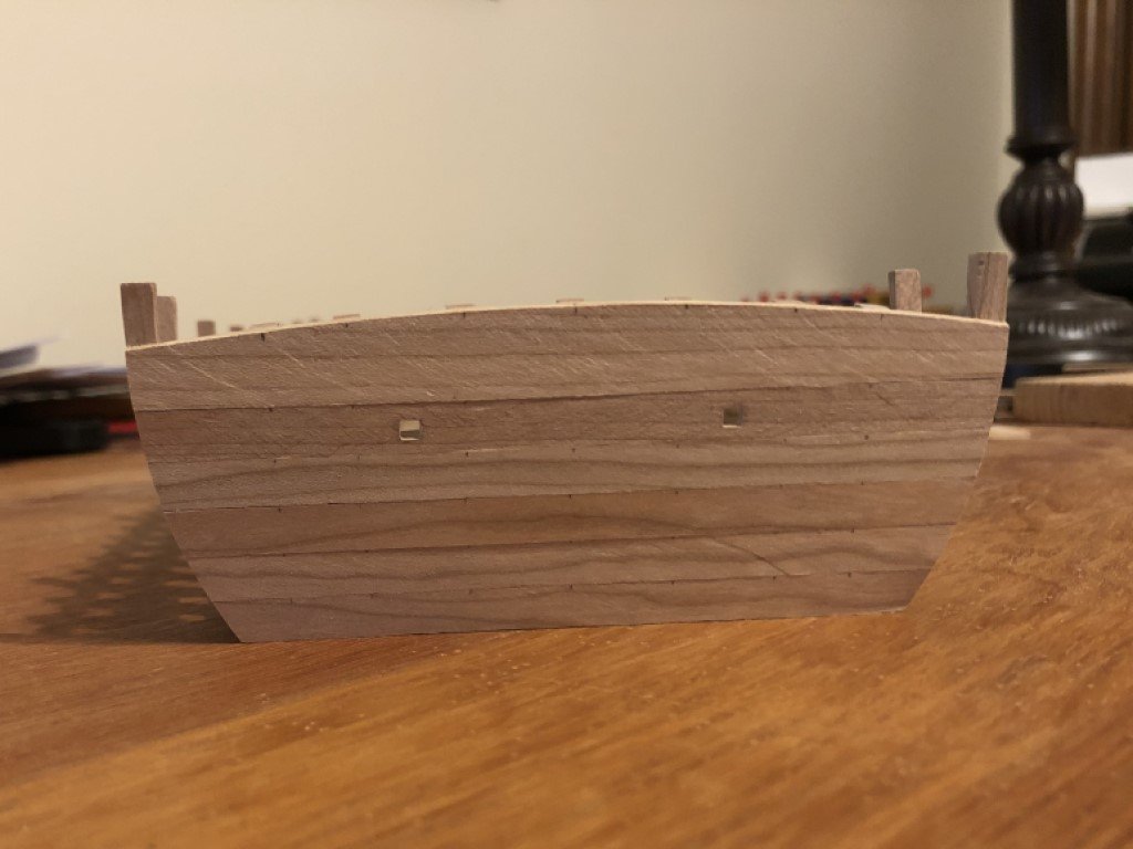
Today was nice here - 70 degrees - and I was really sore from moving huge rocks yesterday, so I got the day off from 'chores'! That gave me the chance to sit outside and finish the basic exterior fairing of the dredger's hull. This was done with 100 grit sandpaper. After the bow and stern areas are planked the sides (and bottom) will get a bit more smoothing with a finer grit. I also made up the 1.5mm material needed bow and stern planking. The first (bottom) stake - front and back - has been attached. The next five strakes are straightforward. The one that follows needs to have 2 lights / windows cut in and the last (top) strake takes on the camber of the deck.
- 199 replies
-
- 11
-