Greg Davis
-
Posts
807 -
Joined
-
Last visited
Content Type
Profiles
Forums
Gallery
Events
Everything posted by Greg Davis
-
 Andy - Thank you! I should probably brush up on locomotive anatomy! Greg Javlin - I wish there were more static locomotive kits available. I got the pair of these BR86's because (1) they're available, (2) they looked like got introductory plastic kits, and (3) I had already bought the 1:72 scale Dora Railgun kit and wanted to put a couple of locomotives behind it. Actually, I go back and forth on how much I like tank engines in comparison to locomotive / tender combinations; but there is little available (that I could find) in 1:72 scale. Because I tend to have a pension for buying too many kits, among other things, I have a 1:35 Trumpeter version of the BR86 (together with some Eduard PE) in my stash. That one I would like to be more detailed and refined than the 1:72 Hobby Boss version. Thank you for the wonderful comment on BR86 (1), and I hope that sometime I see you putting a locomotive together! Greg
 -
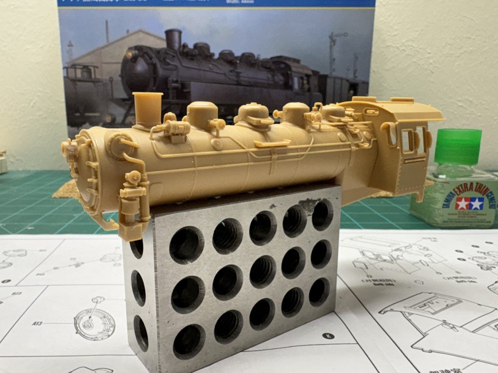
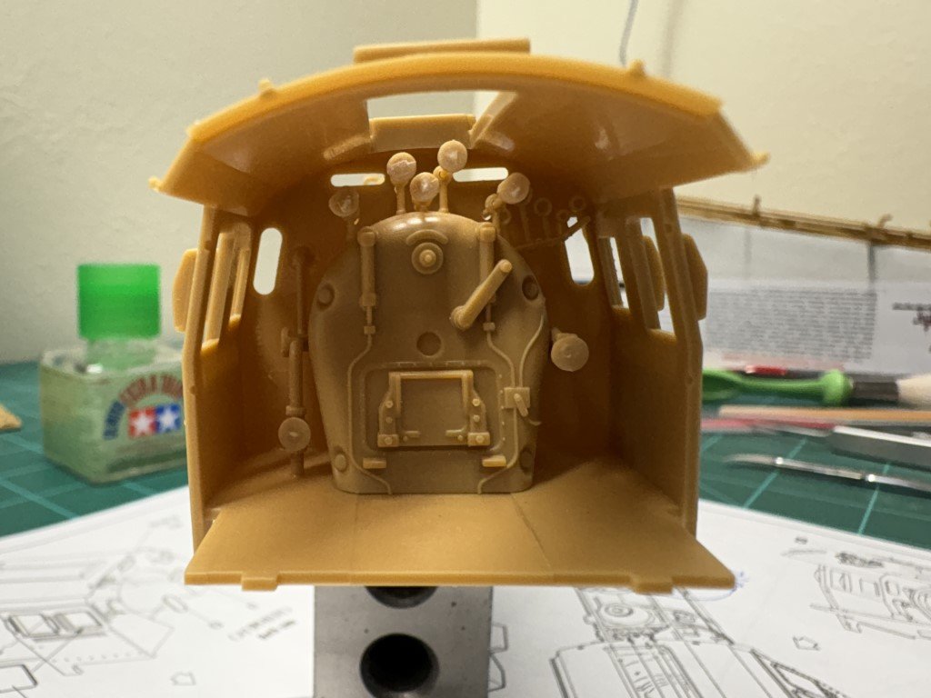
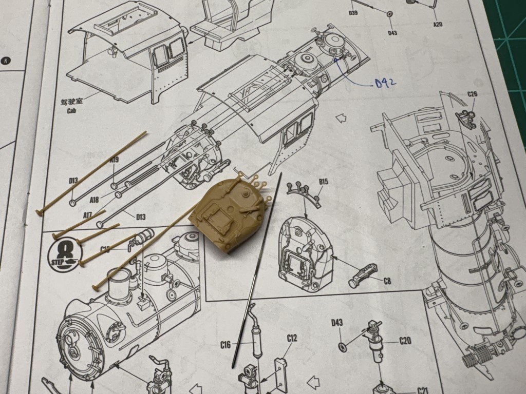
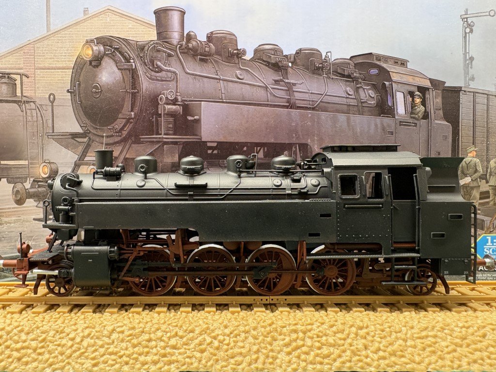
Yesterday and today I was able to make progress on the boiler / cab assembly: The control handles are not all that great, but they cannot be seen very well upon completion so I'm not concerned. I don't know what the part near the smoke stack (not the bell!) is called, but you can see a tube that comes out the front and then bends down to the boiler. This tube was missing from the part in this kit and needed to be added from spare material - the tube was correctly formed and attached on the first BR86 kit I made. The only other thing I will note is that there are 6 value handles on the boiler assembly and they are very hard to attach as provided; however, if you drill a small hole in the middle they go on quite nicely. One thing to look out for is that the 5 control rods that pass through the cab out to the boiler must make it through part B15 and the holes are a bit too small for them to pass. I recalled this from the first BR86 I made. There I didn't notice until the piece was secured in the cab, so I reduced the diameter of the rods to get them in place. This time, I used a small reamer to enlarge the holes in B15 before it went into the cab proper. This was a more satisfactory fix. By the way, the holes the rods pass through the cab back are not problematic. Part C26, the gauges in the upper right, is not fun to insert! This completes Steps 6 - 8. Just two more instruction pages of work before painting commences.
- 45 replies
-
- 10
-

-

-
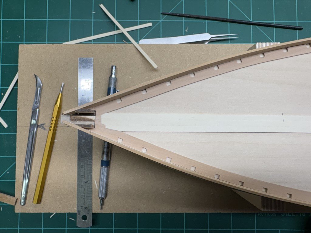
After a little cutting and chiseling, the first nibbed plank is in! Not sure how long the whole process will take - but probably best to take it one plank at a time.
-
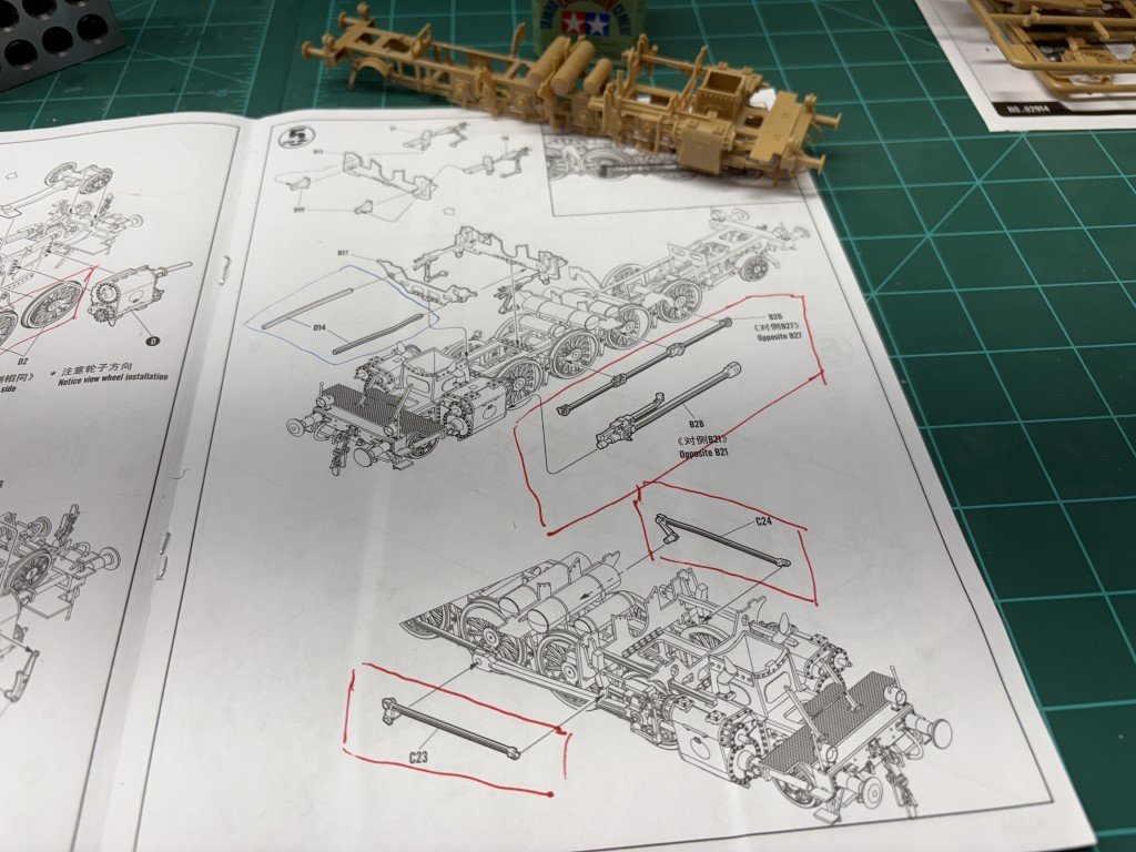
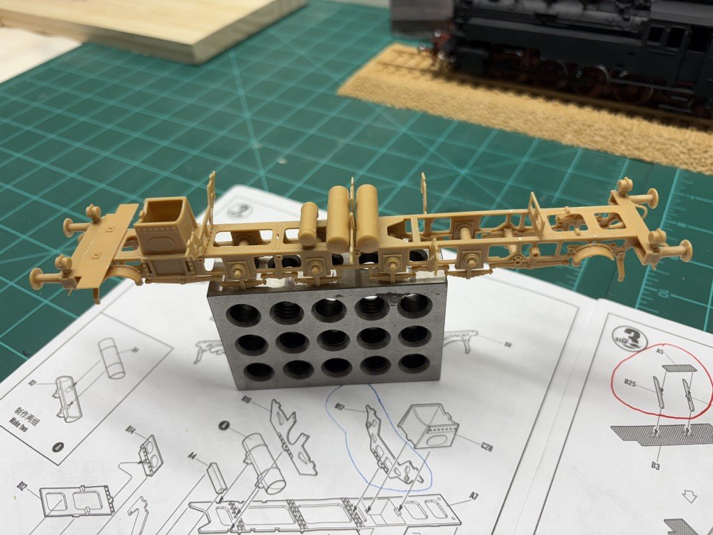
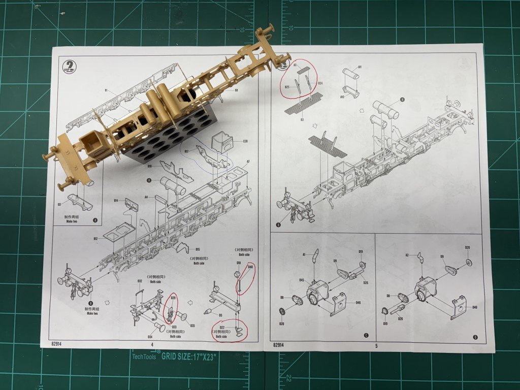
Did what I could from Step 5. Mostly beginning work on the running gear near the cylinders. The subassembly on the upper left of the instruction sheet was the main piece of work. The five pieces go together pretty well with a little fiddling to get the linkages into position. The beams circled in blue are the one's I mentioned earlier as being a bit troublesome. Like in my other BR86, I needed to reduce the cross-section so that the beams would fit through the openings in B17. The only other thing of note is that I didn't glue the linkages or the beams until the whole assembly was in the correct position. It is really important that the linkages can be moved as the subassembly is put into place. Here's a better view of the bit of work: The rest of the running gear - outlined in red will probably be added during the final assembly. However, I may change my mind and add in all but the wheel linkages B26 and B27 before painting. Next the instructions turn to the topsides.
- 45 replies
-
- 12
-
-
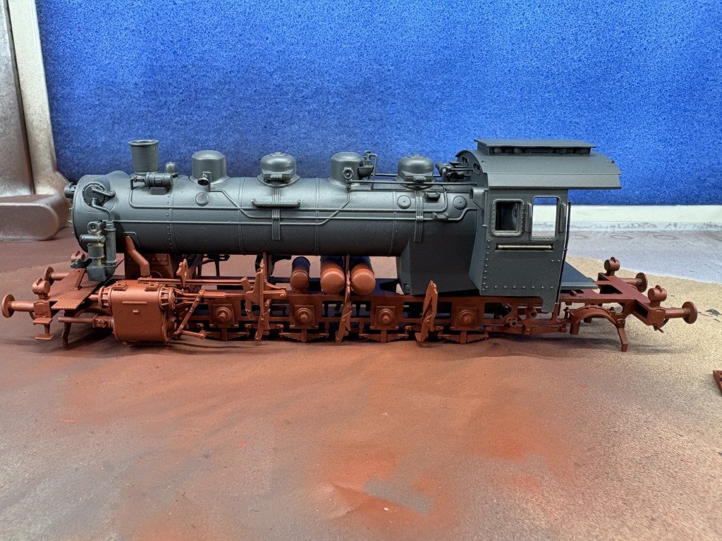
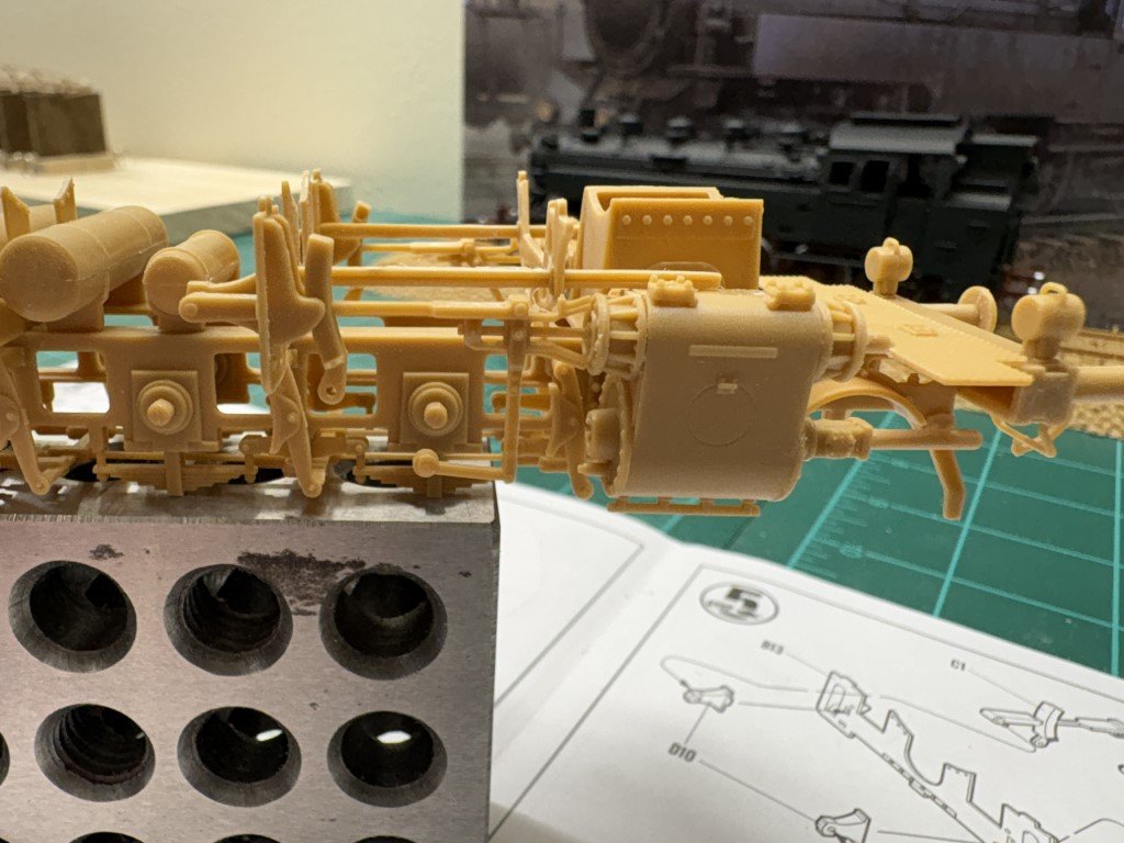
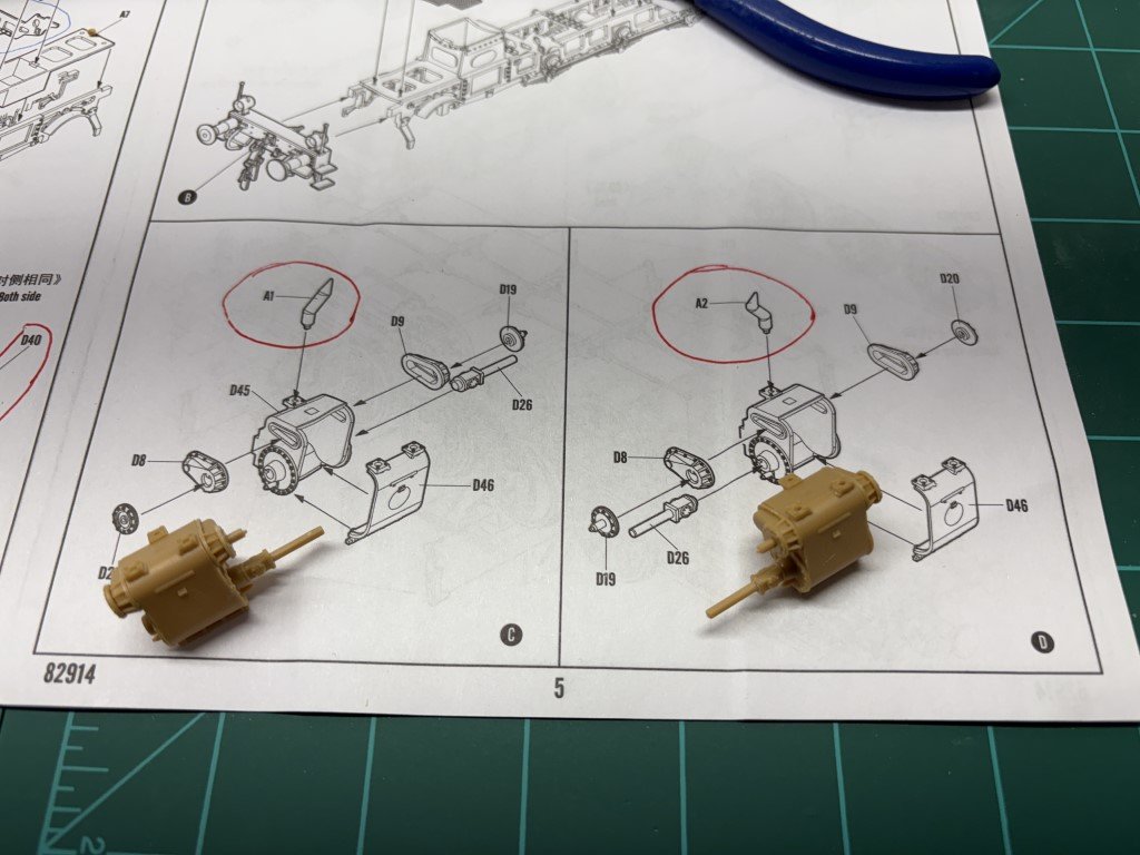
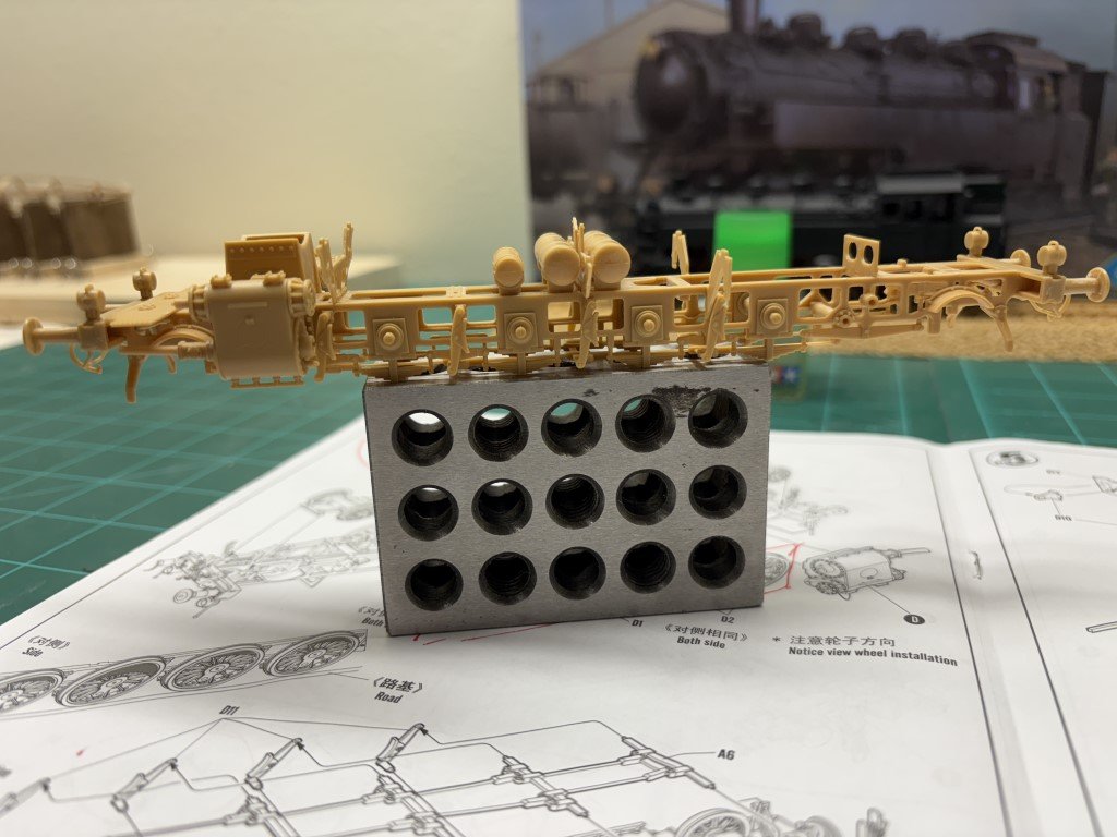
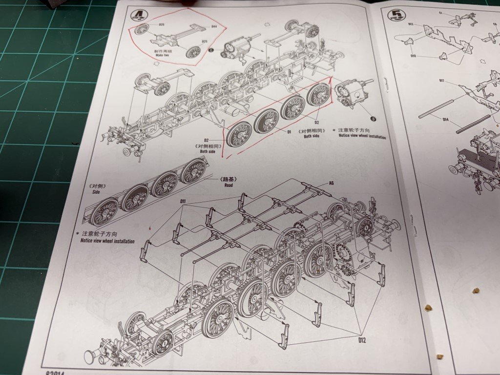
Cylinder subassemblies were completed and installed today. I didn't attach parts A1 and A2 - pipes from the boiler to the cylinders at this time. The top of these pieces rest on the boiler assembly and are more easily aligned once the boiler assembly is fitted to the chassis. Here's the cylinders attached to the chassis. The brake system has also been added. I think the brake linkage (A6) is one of the most interesting pieces in the kit - to bad it is nearly invisible on the finished model. This is what the instructions suggest you should do in Step 4. The wheels will be painted separately and added in the final assembly process.
-
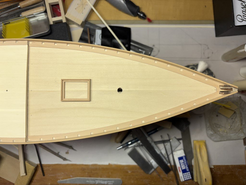
First plank laid on the foredeck! I always give the first plank quite a while to dry before pushing additional planks against it - so more than one can be added tomorrow.
-
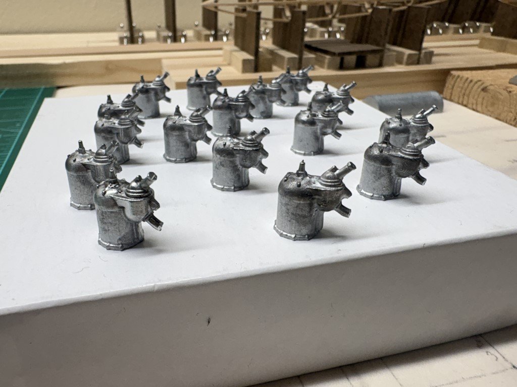
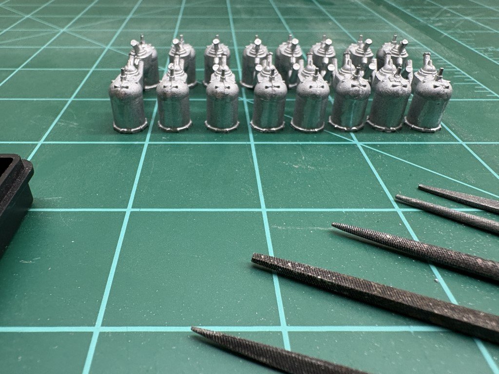
The 16 castings have been cleaned up. I cut off most of the exhaust pipes, leaving a stub to attach new pipes to later. They were run through a couple of cycles in an ultrasonic cleaner. Looks like they are going to the paint booth next! I'm going to try liquid mask on the parts I don't want to paint. They're going to get some primer this time - the 14bis engine was brush painted and has color straight onto the castings.
- 288 replies
-
- 8
-
-
- Santos Dumont No. 18
- hydroplane
- (and 1 more)
-
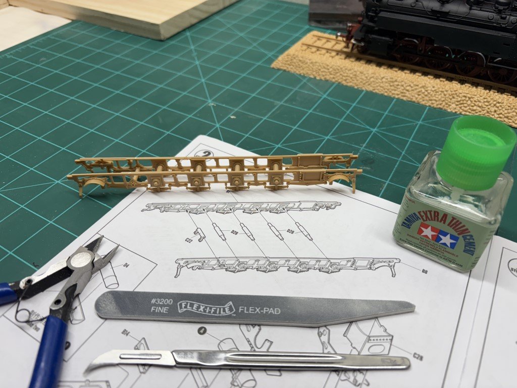
Here's the start of my work - the chassis sides with axles. I'm using Tamiya Extra Thin Cement, I don't know if this is the best choice, but it does seem to be commonly used on build sites I've looked at. I don't know if I should be getting some assortment of glues; i.e., should I have different glues for certain situations? I got an assortment of Flex-I-file. I like the range of grits, but I don't foresee them lasting long as there is already some separation of the sanding surface from the stick. I find this surprising, given the cost. For my wood boat work, I often get sanding sticks from the manicure isle. In the above picture, the only pieces glued were a cross-member (left of the axles) to the two sides. The axles are just press fit here. While everything seemed to be pretty square, I used the large and small rectangular top pieces to finish the alignment. After that other details were added. I should have reviewed my notes from BR86 #1 and not glued in part B17 (circled in blue above). The instructions show the part being added here and also in a couple pages. The second time it is noted is probably a better time to add it. At least that's what I had concluded a couple of weeks ago. The reason is that there will be two beams that go through B17 near the top and in the last build the fit was so tight I needed to reduced their cross section to fit. I felt that it would have been easier to make these adjustments with B17 off the model - oh well, I live and don't always learn! Below is the instructions for what I have assembled so far. The pieces circled in red will be added later. The couplers drop down below the top of the rails when the engine is complete, so they can't be added until the very end. The poles and steps are better left until the boiler, coal compartment, and cab have been installed. The rails for the step in the front of the engine fits into notches on the boiler assembly; leaving their assembly until later makes alignment easier. Cylinder assemblies are up next.
-
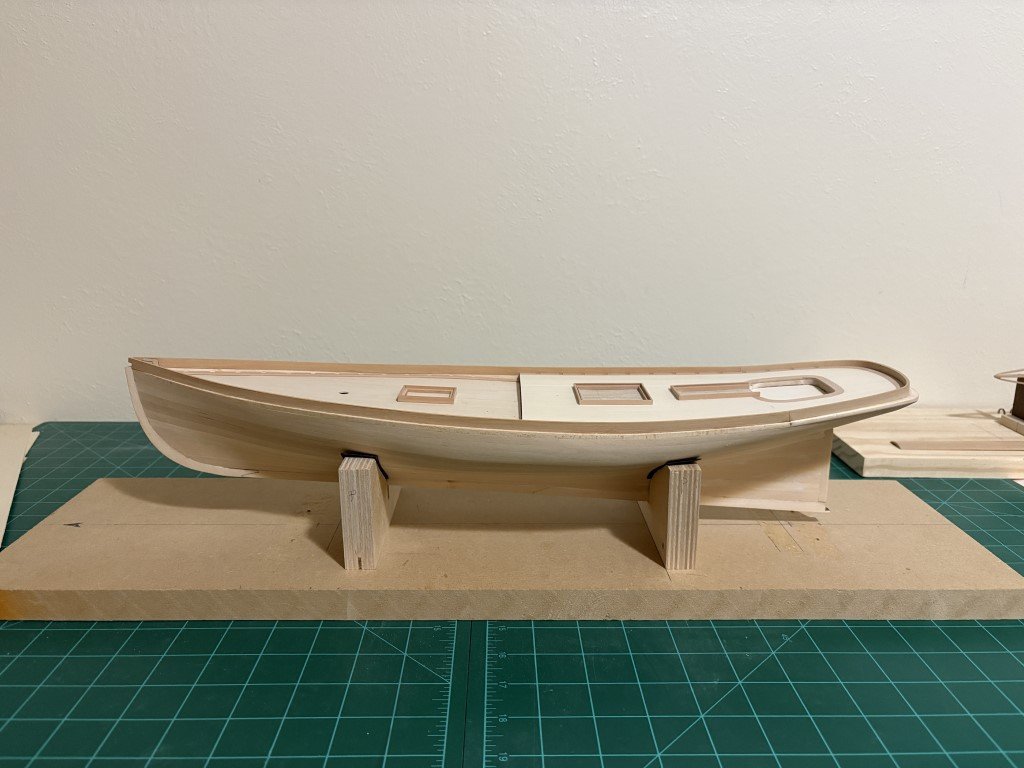
Got the new cradle made up today. I always find making these to be tedious - getting the bevels in the supports and having most everything level is never fun for me! Now that it is done, I can get back to the planking; probably start up again tomorrow.
-
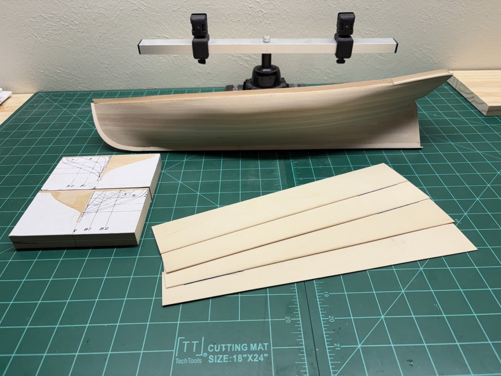
Today I milled enough 1mm thick holly to complete the foredeck. I'm also getting a new building board made up to better support the hull through the deck planking phase. I need something much more stable when time comes to cut into the waterway for plank nibbing.
-
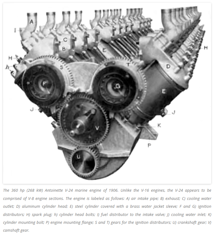
It could be worse! From this very interesting article by William Pearce: https://oldmachinepress.com/2016/05/28/antoinette-levavasseur-aircraft-engines/
- 288 replies
-
- 4
-

-
-
- Santos Dumont No. 18
- hydroplane
- (and 1 more)
-
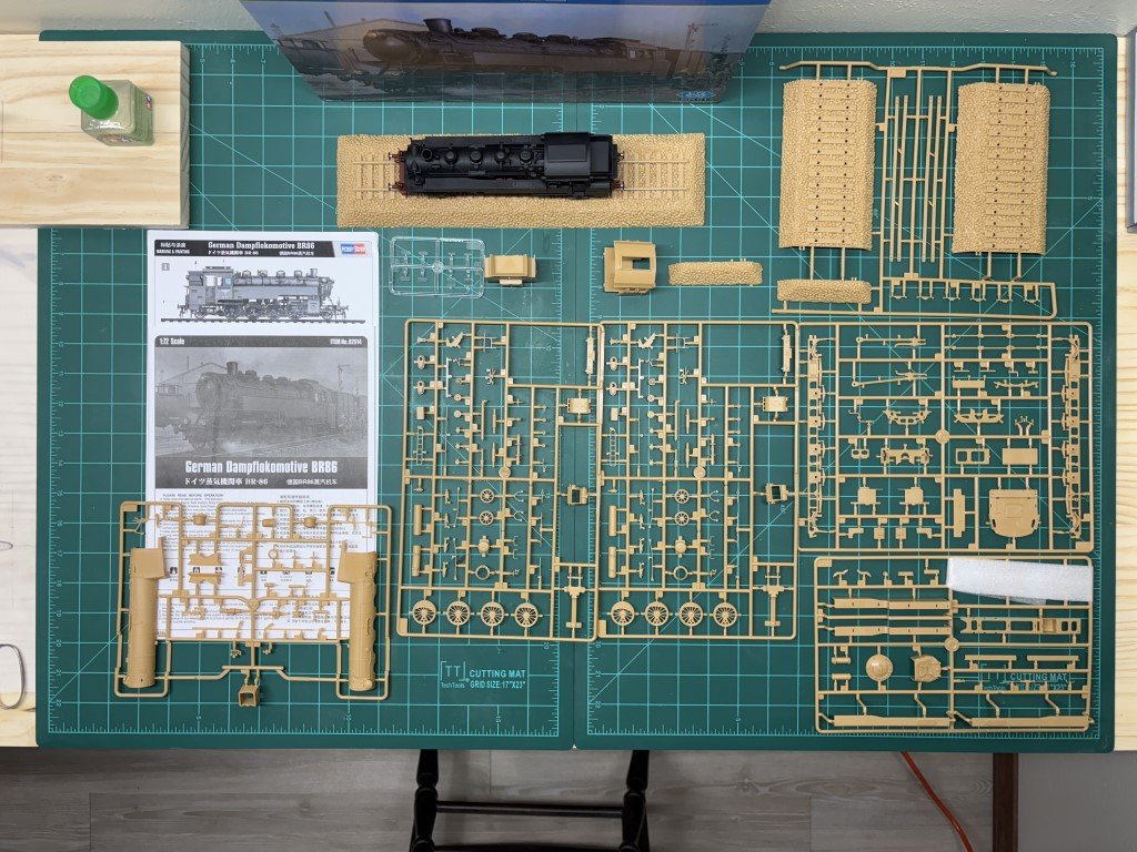
Not long ago I decided that I would like to build a few plastic models. Kits Plastic models that I've seen over the past several years have amazed me in comparison to those I played with some 50 - 60 years ago. The skills that plastic modelers bring to the table are incredible as well. Painting skills are often unbelievable to me! So I jumped in the deep end bought a few kits (not confessing to how many). Steam locomotives have been a longtime fascination of mine as well - so when I saw that there are some nice static plastic locomotive kits available, some made their way to my house. This past December, I assembled my first - a Hobby Boss 1:72 scale BR86. I also got to practice a bit with a spay brush and now it's now ready for a clear coat, a few decals, and a little weathering: In this forum I will be showing my work on building a second model of this locomotive. As I go along, I hope that will be interest in the build. Perhaps some of you will be able to provide me with comments on how I can improve my work with plastic. Yes, there is a reason that I've chosen to build two of these engines - it is so that they can 'push' the Hobby Boss 1:72 scale Dora Railgun someday. This is why the rails / rail bed hasn't been painted. To display the railgun and locomotives track will need to be laid longer than the kits account for. Here's what comes in the kit: 5 spruces of parts for the engine, another with some roadbed and rails and a small one representing glass. The cab and coal bunker are included separately as well as a few decals. There is a 12 page instruction manual printed in black and white along with a two sided glossy sheet displaying two painting schemes. The scheme in the above picture shows the BR86 all in various shades of black and grey, the reverse side shows a scheme where the wheels and chassis is in red. I chose the scheme with red for the first model; this one I am thinking of doing in the grey scheme. So again, I hope that some of you find this topic interesting and also are willing to provide some guidance to navigate this realm of modeling. Thanks, Greg
- 45 replies
-
- 13
-
-
-
Spent literally hours cleaning up castings today and there is still more to be done. Thanks to Alan (AON), I think I've been reined back in with regard to the engine portion! Painting has swung to the favored position now. So now the pressing work is to finish cleaning the flash and polishing the top of these castings before priming and painting. After sleeping on the topic, I believe this is really the right thing to do. If there comes a day when I want to work on my metal skills a whole new engine - starting with a better engine block - could be a great project. I don't remember if I mentioned it in this forum (or if it was in the 14bis forum); there is a flaw in the kit engine block that one can not get past: the cylinders are not staggered correctly, the row that starts in front should be on the opposite side of the block. So, custom cylinders, etc. on the kit block would still have an issue! Back to the files.
- 288 replies
-
- 8
-
-
- Santos Dumont No. 18
- hydroplane
- (and 1 more)
-
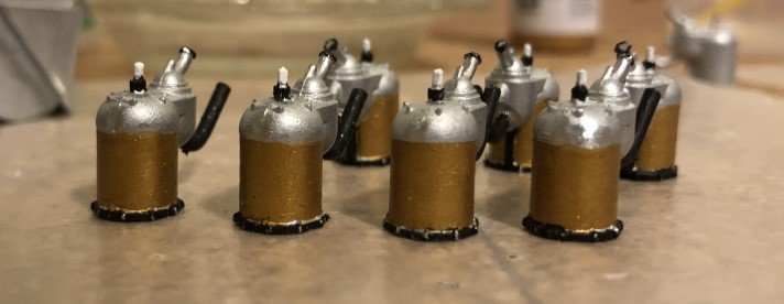
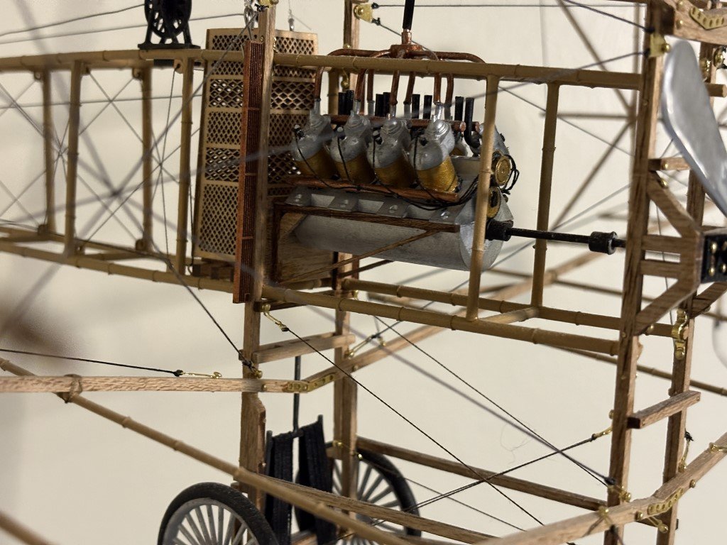
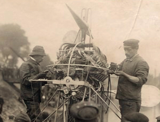
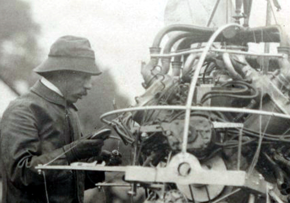
It would be a safer alternative! This is the set of cylinder assemblies from my 14bis model - where I used brass metallic paint. I also used copper paint for the plumbing and black for the exhaust pipes. The final result was like this: Looking at it again, I don't think it looks to bad! Still don't like the engine mounting brackets, but those have been removed and are being replaced for the V16. I had just been thinking that maybe it could be improved upon. But now that you have me thinking more about it, perhaps a more basic approach will be just fine as there is no way I'm going to be able to model a vast amount of the engine detail: These incredible pictures were provided to me by the highly regarded Santos-Dumont historian Henrique Lins de Barros.
- 288 replies
-
- 7
-
-
- Santos Dumont No. 18
- hydroplane
- (and 1 more)
-
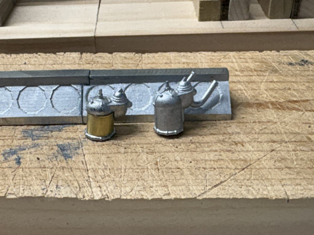
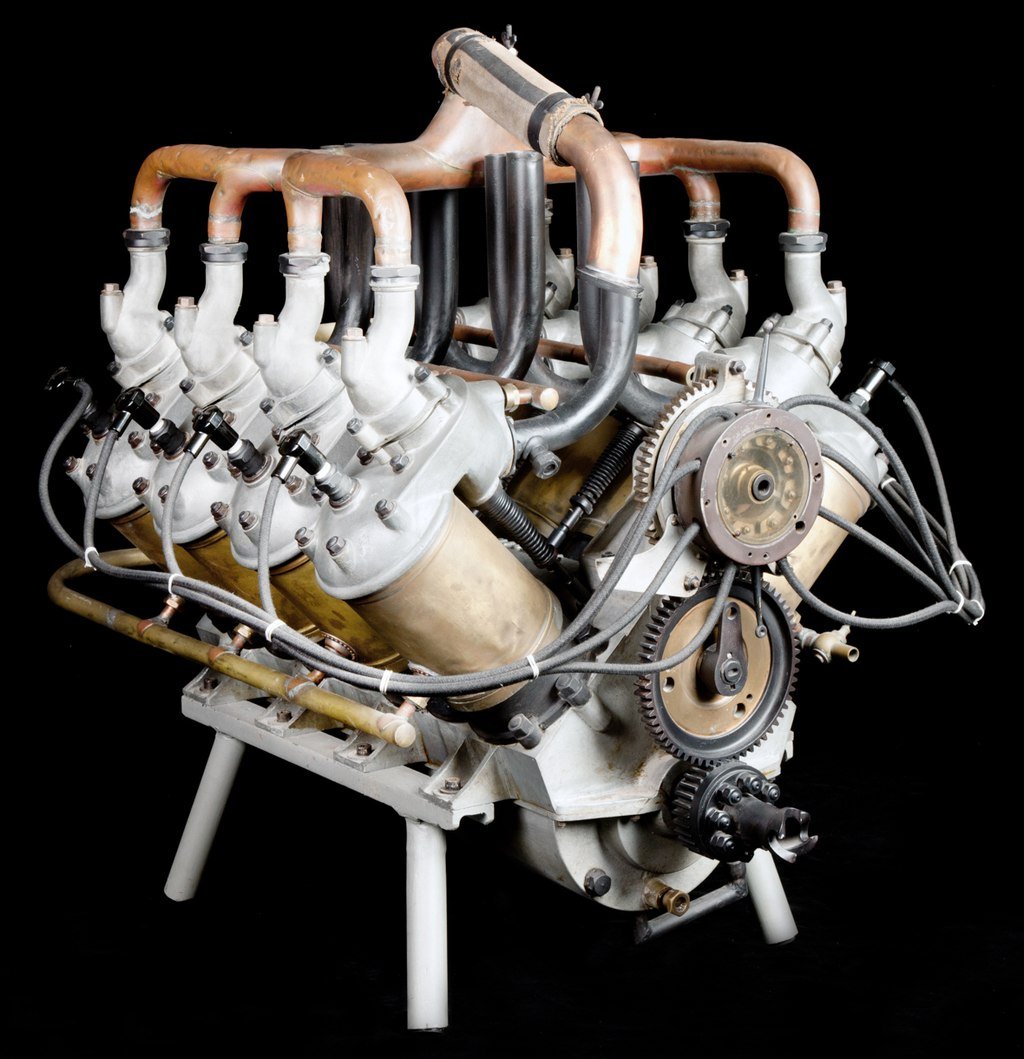
Today an experiment with the cylinder casing / water jacket. I think the result is promising: I wondered if I could mill out the water jacket portion of the casting and then replace it with brass to get a look closer to: The exhaust pipe of the casting was removed on purpose - for the hydroplane the exhaust pipes go down instead of up. The gas intake manifold was removed errantly. Fortunately, I had an extra casting from when I made the Santos-Dumont 14bis airplane. Now I have 16 castings left and no room for mishaps like this! For the 'keepers', the bolt ring at the bottom will be blackened and the heads will be polished after I remove as much seam flash as I can. All the brass water jackets will be cut at the same time to ensure they are all the same height. (The experimental one was a quick cut off and is clearly to short.) I plan on making the exhaust pipes from brass tubing and the fuel system from copper. I'll also try to add in the springs / value lifter rocker assemblies. That will probably be the limit for me in terms of detail! Then the cooling system will be attended to.
- 288 replies
-
- 7
-
-
- Santos Dumont No. 18
- hydroplane
- (and 1 more)
-
Organizers arrived, were assembled, and filled - time to try out the new setup!
-
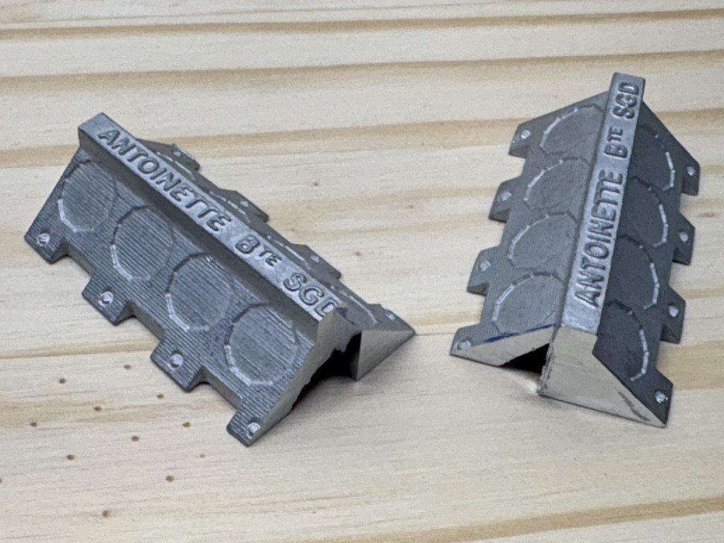
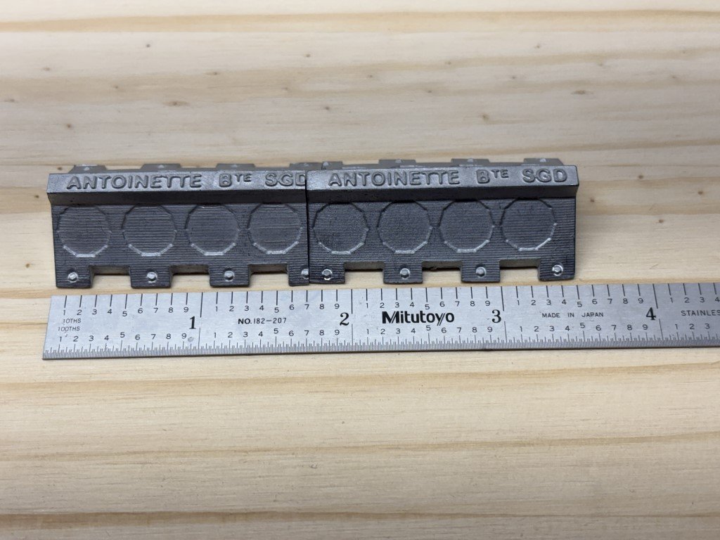
I cleaned up the casting a bit - flattened the bottoms, milled off the lettering and mounting brackets: The two pieces are epoxied together. Suitable mounting brackets will be added back in - I think I can make them out of square tubing. I'm considering notching the material into these casting before adding the semi-cylindrical bottom castings. Then the top part of the square tubing can be removed, leaving mounting brackets with a triangular profile.
- 288 replies
-
- 7
-
-
- Santos Dumont No. 18
- hydroplane
- (and 1 more)
-
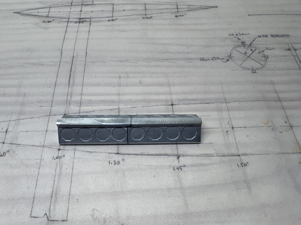
I know its been a long break, but I have started up again. This time I am working on the V-16 engine. During the break, I spent quite a bit of time trying to learn more about the Antoinette V-16 that powered the No. 18 hydroplane. Unfortunately, like plans to the hydroplane, it seems that plans / exact dimensions for the engines built by Levasseur no longer exist. There are a number of photographs of their engines and some specimens still exist. It also is the case that the engine designs were in a nearly permanent state of flux, with modifications being done often. Of course, there is a lot of commonality at the same time. So what I end up with will be more of a 'representation' of the power plant as opposed to an accurate scale model of it. I do hope that I capture the prominent elements so there is no question as to what it is a representation of! When I first considered building this model, I planned on taking two of the Model Airways 14-bis Antoinette v8 engine kits and building a V-16 from them. This seemed sensible since the V-16's were basically concatenations of two v-8's. After a while, I thought that I could craft an engine from scratch - milling the block from aluminum, etc. I've now come back to my senses and have committed to working from the two kits I have. Today, I actually made the first step: sections from each need to be removed in-order to get the correct cylinder spacing. In a zig-zag pattern, I needed to mill 0.1" from the front of one piece and the same amount from the back of the other. The two pieces need a little fine tuning, but match up pretty well already: The lettering will get removed and something should be done about the mounting brackets! Hopefully (more) regular progress will be made now.
- 288 replies
-
- 10
-
-
- Santos Dumont No. 18
- hydroplane
- (and 1 more)
-
Paul Thanks for the info - his process makes sense (and a lot of other interesting videos as well)! Greg
-
Packed up a whole lot of stuff so that I could get tables and new lighting in place. Unpacking after the new organizer cabinets arrive at the end of the week.
-
Thanks for the details - I wonder if the flow improver / thinner / retarder mixture is a big part of why your airbrush is keeping pretty clean on its own.
-
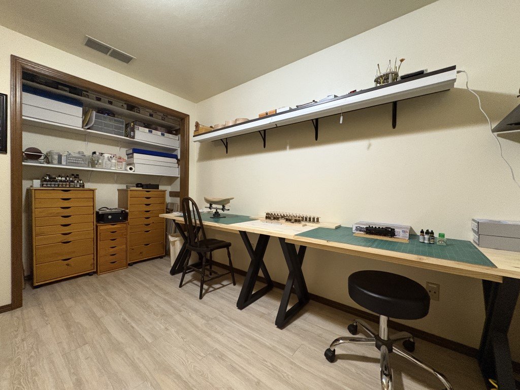
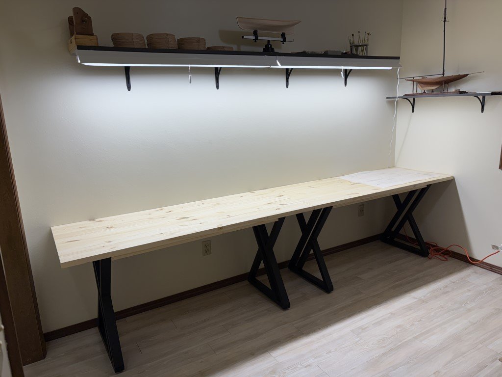
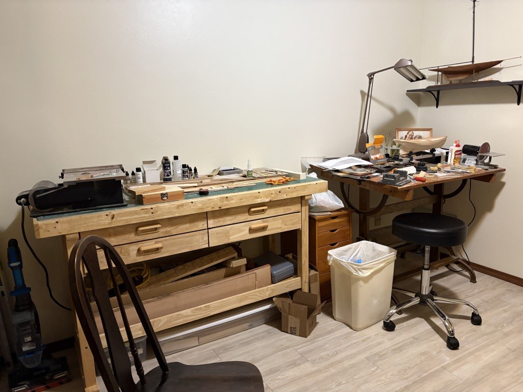
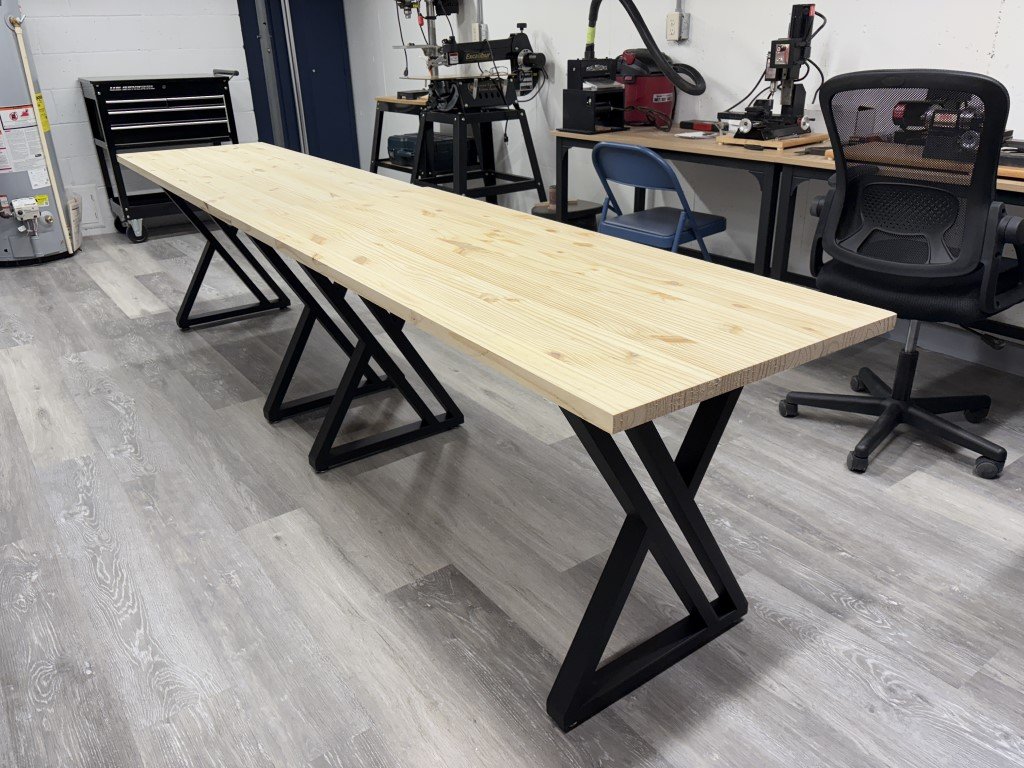
Not much modeling today, instead I'm working on revamping my workspace. As it is in transition it is a mess right now. For quite awhile, I have been making use of a couple of work benches from Harbor Freight and a drafting table that was my Dad's. While I've had the HF benches for years, they have always had a couple of disadvantages for me. First the drawers don't fully pull out so they are difficult to fully utilize; second, and most importantly it is very difficult for me to sit near the bench and work. The drafting table is great when I am drafting - which is infrequent - but is deeper than I like on most days so it isn't the best use of space for me either. As I get older, I find that I would rather sit than stand when working, hence the revamp. So today I got a start on the remodel by building a pair of benches that I can sit by. They are each 5 feet long and 2 feet deep at a height convenient for sitting on a typical office chair. They will get moved out of the basement and up a couple flights of stairs soon. I plan on putting a shelf above the benches for storage and have a couple of shop lights attached to provide better work light as well. I have additional storage drawers on the way to hold what was in the HF benches (and more). More modeling soon!
-
I'm also using Vallejo Air, but I have not thinned and/or used any additives. I've taken the company on face value when they say that the paint can be sprayed straight from the bottle. I do have some of the flow improver - I should give it a try!
-
I started to figure that out today - in the afternoon I brushed some red, this evening I did some black. After the red, I had run cleaner through the brush and disassembled / cleaned everything but the needle. After the black I took it all apart - including the needle and yes, there was red paint stuck pretty well to the needle! All is clean and good now, but the cleanup is time consuming. On the upside, there is no way I could have gotten this nice of a finish with a brush. So I think I will probably become an fan of the airbrush.
-
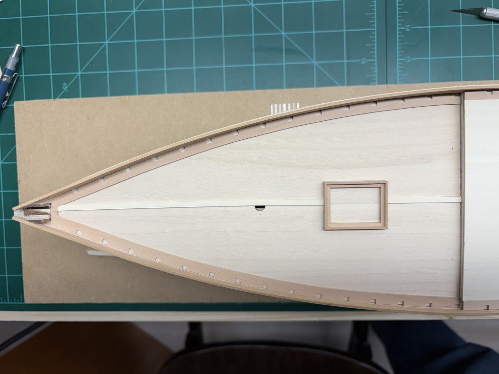
The waterway / margin planks have been shaped, notched for timberheads, and glued in place on the foredeck. More material was milled and made into a combing for the forward hatch. Nearly time to start planking the deck! I'm 90% sure that I will be going with the standard nibbed planking pattern. As an aside, the BR-86 is getting some paint / I'm teaching myself airbrushing!