Greg Davis
-
Posts
807 -
Joined
-
Last visited
Content Type
Profiles
Forums
Gallery
Events
Everything posted by Greg Davis
-
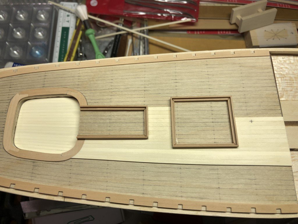
 Got a chance to work some more on this project this evening. I marked out margin planks to match those on the aft deck, the forward hatch location, and mast location on the subdeck. Took a few photocopies of the piece and then glued, clamped, and weighted it to the model. Spent some time making up some more 1mm pear for the waterways. I had some more pear that I have been using on the model. Unfortunately, it was 4mm thick and I really didn't want to mill off 3/4 of the wood to make the waterways. Decided to see if it was possible to split the wood in half - turns out that I could. First using successive cuts from both sides of the piece with a slitting blade on my table saw I was able to cut all but about 1/4" of the material out. The remaining material was cut with a razor saw. I ended up with two strips 1.5mm thick. They cleaned up and thinned to 1mm quickly in the thickness sander. Templates for the waterways are now rubber cemented to the pear and await the scroll saw!
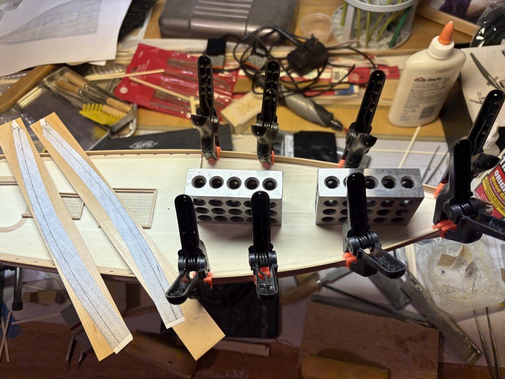
-
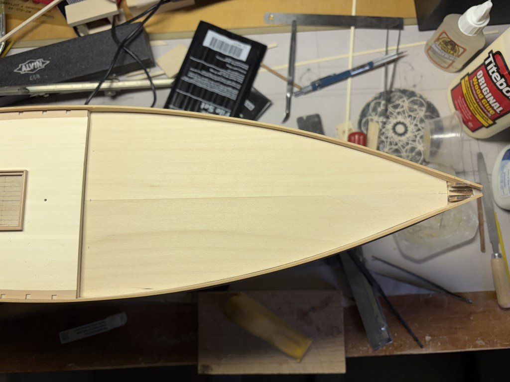
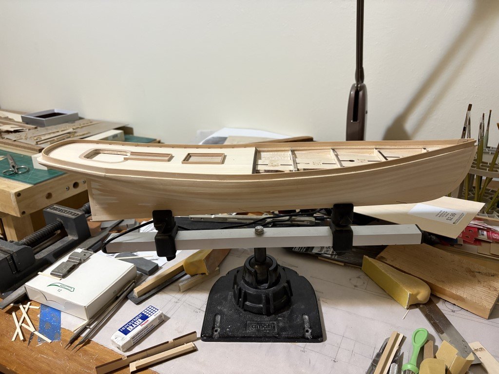
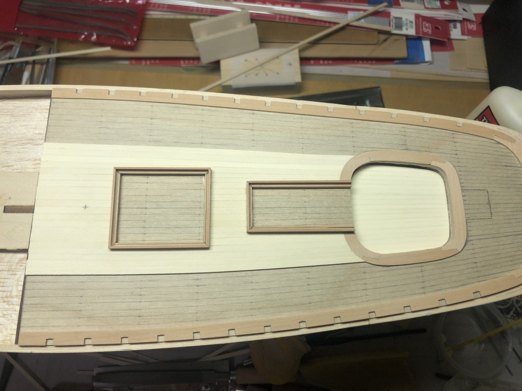
Subdeck completed - I decided to make this one out of 1/32" basswood instead of the plywood like on the aft deck. Next step will to mark out the waterways / margin planks - after that I'm going to need to commit to a planking scheme!
-
the same is happening to me!
-
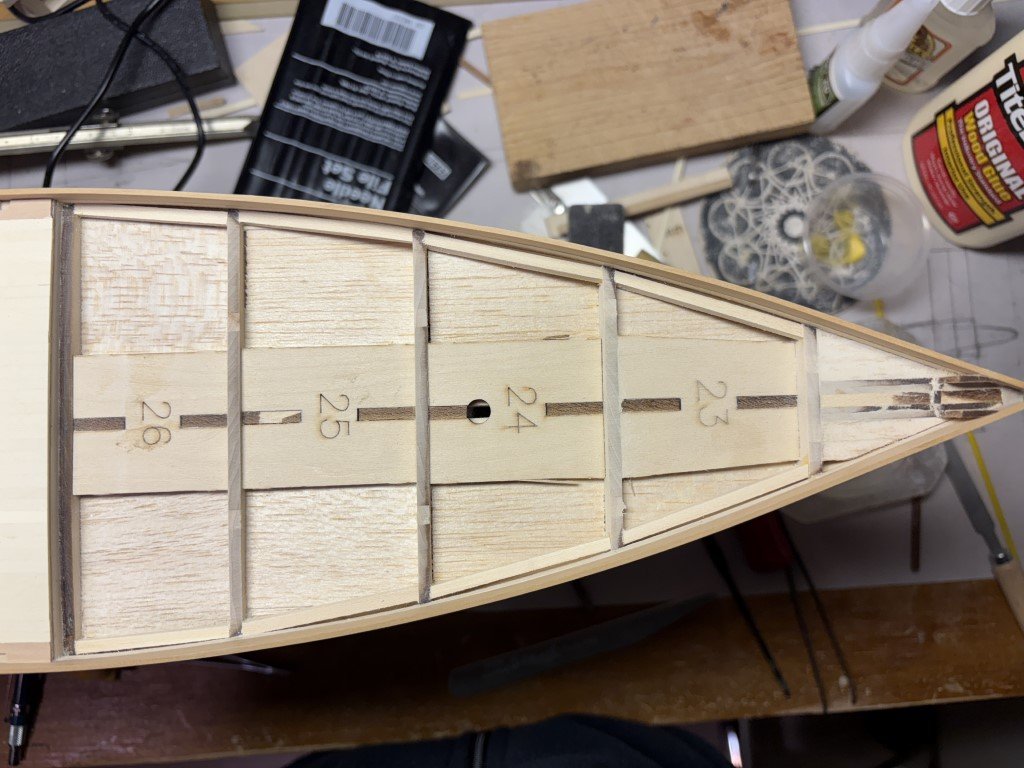
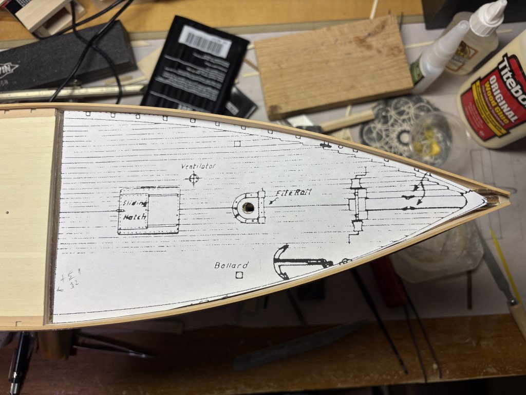
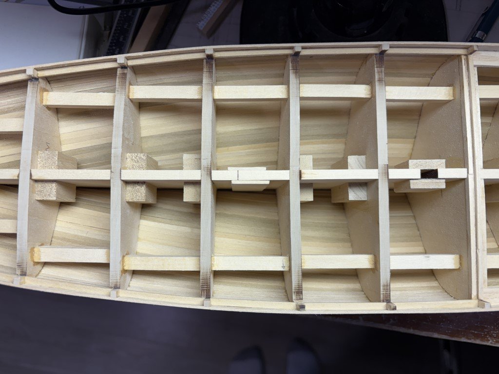
Making preparations for the foredeck. I added strips of wood between the bulkheads and near the bulwarks so the subdeck can be secured well in this area. Once they were in place, I faired the 'deck beams' and support pieces. Then I made a copy of the foredeck plan and was glad to see that it matches the foredeck quite a bit better than the aft deck plan matched the aft deck. Next step will be to actually fashion the subdeck. Still haven't made a decision on the planking pattern for this deck - nibbed as in plan or herring bone pattern as illustrated in Chapelle. Votes?
-
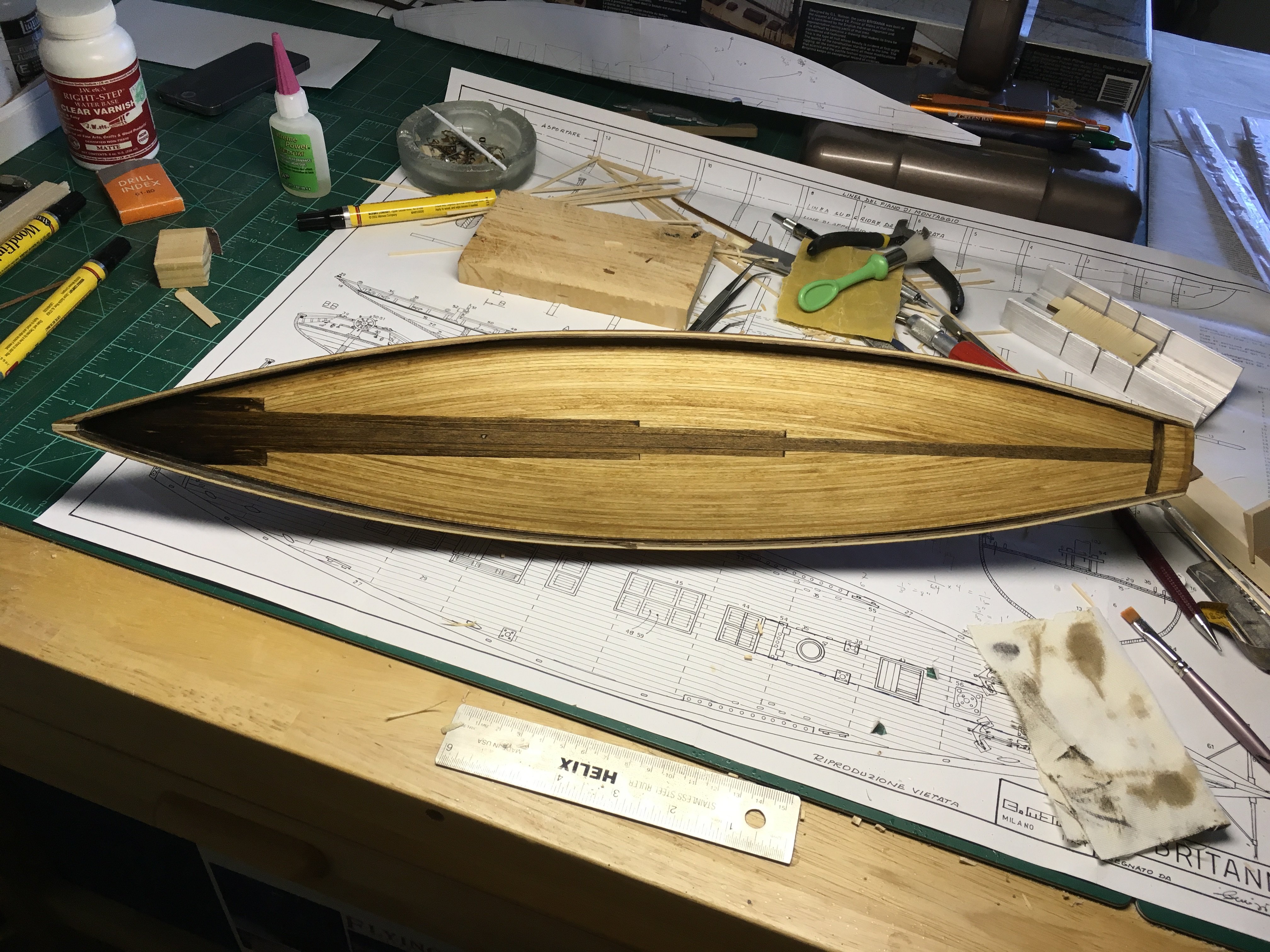
The oxidation idea sounds plausible. It is still a curiosity to me - there was no sunlight hitting the hull at anytime and the 'discolored' planks are discolored from front to back. Here is a picture of the inside of the hull: There is little, if any, change in color of the pieces that had been taken from a laser cut sheet; i.e., bulkheads, stem, stern, keel. It seems to be isolated to the strips that were provided to plank the model. I've a number of MS kits and in many the planking material has a good deal of color variation (and at times quality and milling variation). I wonder if they don't always do a good job sourcing strip wood for their kits.
-
This is beautiful work - I've often been tempted to try this model! Out of curiosity, how well does the glue - both Titebond and CA - hold on your oiled and waxed pieces of wood? Greg
-
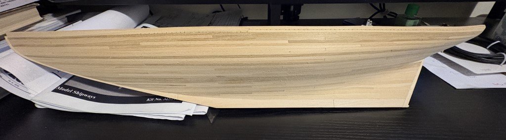
I started a MS Bluenose kit a long time ago. After planking the hull I lost interest in the project and it has been sitting on a shelf out of the sun in a dry room where the temperature remains pretty constant all year long. When the hull was planked there was variation in the color of the basswood strips that had been supplied with the kit. About 25% were darker in color. Being new to the hobby, I used what was supplied and 'randomized' the use of strips. I have a picture of the hull taken in September of 2012 were the differing shades can be seen: I've been moving things around and happened upon the hull recently. Most all the strips have gotten a bit darker over time, but the darker strips (from early on) seem to have darkened dramatically more. Not being overly educated in wood, I am curious as to what is going on here. It is of particular interest as currently I am using holly for the first time on a model and the first holly I purchased had a good deal of bluish color mixed in. I now understand that the holly discoloration is likely a mold. Does basswood / limewood suffer similarly or is this completely unrelated. In advance, thank you to anyone that can shed light on this phenomena. Greg
-
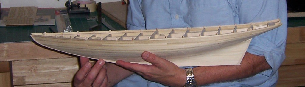
Bulwarks have been reinstalled. Beforehand, I did take the opportunity to smooth out the interior side of the bulwarks where the two strakes butt together - easier than if that work had been done with them installed. The hull will still need a little bit of fixing / care due to it being dropped a while back. I'll take care of that work when it is time to paint and copper the exterior. Next up is completing the fairing of the deck beams followed by making a false deck.
-
Aft deck is done for now! Now I will need to reinstall the bulwarks. I wish I could do that after installing the main deck; however, I need to make use of the bulkhead extensions to help reposition the bulwarks. I'm glad that I did not sand down the bulkheads up front after breaking off the extensions. Also glad I was able to find all the extensions in the garbage can!
-
I just made it to one of the margin / waterway planks! Time for an expresso! While it isn't easy to see in this picture, the outermost plank is nibbed into the second plank near the stern so that it was not thinned / shaped to a pointy end. Also, I didn't quite follow the lines on the plywood for the last planks I installed. To keep them as even as possible out to the waterway, I made use of a proportional divider to set the width of each plank as it was added. First taking a sixth of the remaining distance, then a fifth, etc. This was to hopefully guard against having an overly wide (or narrow) plank up against the waterway. It seems to have worked out OK and I will employ the same technique on the other side.
-
I am going to use planks the length of the aft deck to finish the work. This is also how Volk, Davies had presented the ship. I thought I had read elsewhere, that such a planking scheme was not uncommon for this type of a ship; however, I am not currently able to find the reference(s).
-
The remaining planks behind the cockpit went in easily. The planks that flank the cockpit and run the full length of the deck were not. But they are now installed and I like the look that is developing! A dozen planks to go now.
-
A bit more progress - completed half of the planking aft of the cockpit and installed the final two planks that end ahead of the cockpit. Once the rest of the shorter planks have been added behind the cockpit, there are seve planks (each side) that go the full length of this deck. More fun to come!
-
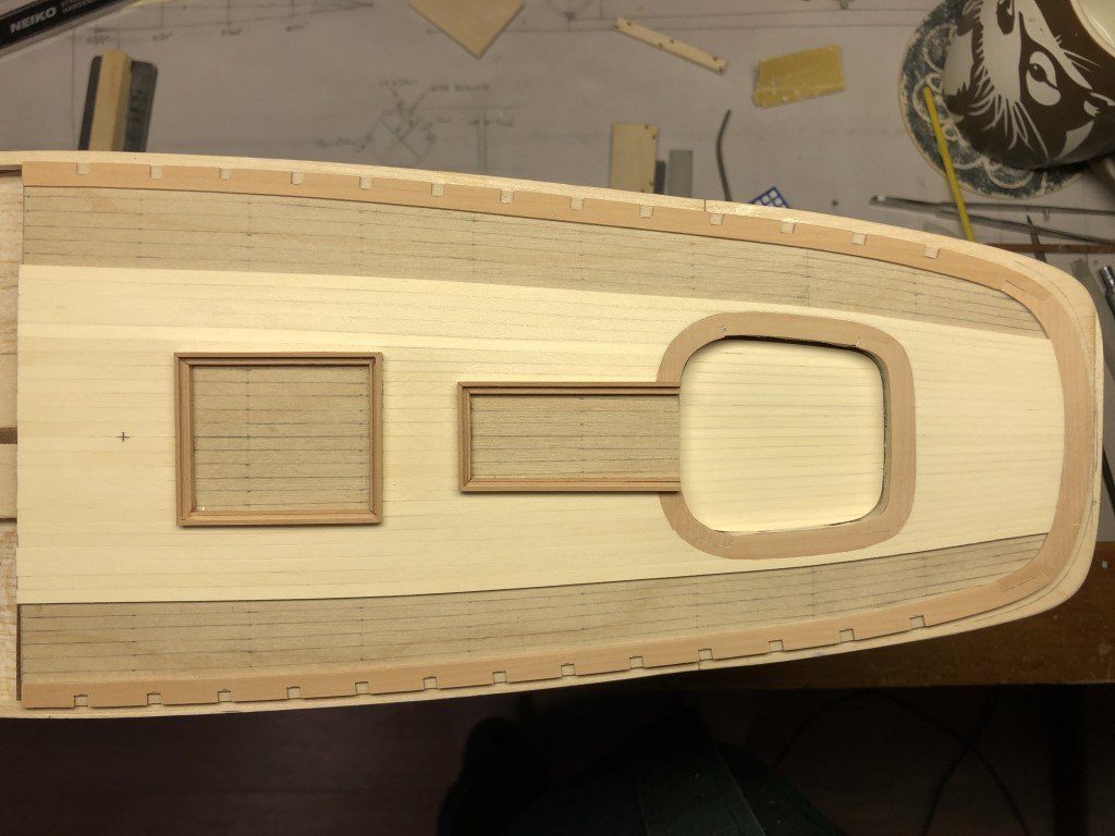
The deck planking is symmetric again!
-
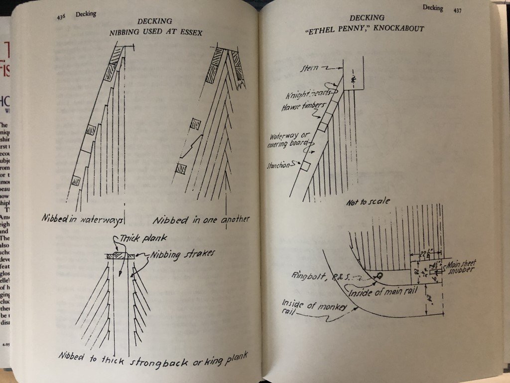
I believe that to be the case also; i.e., decking similar to fishing schooners. The Phantom plans by Campbell show the curved planks aft and straight planks nibbed into the waterway forward. According to Chapelle (The American Fishing Schooners 1825-1935) there were other planking options up front: The herringbone pattern is sort of interesting - can't say I've ever see a model built this way, but I am actually considering it! I started planking Phantom in the middle because I was concerned about working around the coamings and felt this would be easier for me. Last time I planked a deck in a curved manner was on a Mamoli Britannia model; here I did start on the outside and worked in. The decking was all done in 1/16" thick basswood, the curved pieces being 1/16" square which easily conformed to the needed shape. There were no coamings to worry about because all the deck furniture was attached after the planking was done and I had also included wider king planks. When I was working on this model, the website for the K1 Britannia project had a number of plans / illustrations of Britannia that I used as inspiration as to the final look. Since then, their project has been reimagined and the website has been simplified. Now it is not clear if they will meet thier goal of constructing a replica ship - it would be amazing if they did!

-
Got that tough one that passes the skylight fabricated and a few more deck planks in place. I can do one more plank on this side and then I should probably switch to the other side and even the work out. After that it may be best to work art of the cockpit area until it is filled out to match the work forward. The the first plank that goes unimpeded along the deck (on each side) can be fashioned. Those will be pretty challenging to make so that they smoothly pass along the sides of the cockpit margin board - I expect a few tries each side!
-
Put a few deck planks on today - some of the easier ones. The next plank to the starboard is one that is not as easy for me; getting the correct notch for the skylight will be tedious as it will need to drop in about half the planks width at the aft end.
-
Thank you - this one was particularly hard since we had him since he was a puppy and he needed a good deal of care and attention throughout his life. We've also had many pets, most often rescue dogs with many being midlife to senior. It somehow made it a bit different this time. We've never been fortunate to have a dog (or cat) pass peacefully in their sleep, but have always hoped that would be the way they left us.
-
Sad day for me today - had to have our 14 year old dog Phantom euthanized today as his health had rapidly deteriorated and there was no more that could be done to help him. So RIP good friend!

-
Jarod – First, thank you for taking the time to look at the progress I have made on the 1:48 scale Phantom model. I also appreciate the comment on the quality of my work. However, I have been taken aback by your post. I hope that individuals following this build log will have noticed that there are multiple lines of thought running through it. Besides the actual construction of the model, I have attempted to be clear as to the pros and cons of the kit as presented by Model Shipways independent of the modifications that I have chosen to make on my version of the model. The only fault that I can find in what I had written is that twice (posts #75 and #99) I said the model was marketed toward ‘beginner’s’. The reason that I had used the word ‘beginner’s’ was due to the caption of a picture in the instruction manual, on p15, where it is written: “Nibbing” of deck planks at the bow is very difficult to do in a beginner’s model. Also, the 1:48 model seems to be a replacement for the 1:96 model that had been clearly labeled as a beginner’s model (whatever that really means). If one goes to the Model Expo website, opens the PDF version of the instructions for the 1:48 scale Phantom kit and searches for ‘beginner’ just two instances of the word will appear. One is in the nibbing comment noted above, the other is in the bibliography associated with Campbell’s 1962 publication. There is no mention of skill level on the ME website description either. In fact, one could easily infer that the new kit was going to be quite a step up, as in the kit description (and instruction manual) it is written: The kit was originally offered as a 1:96 scale solid-hull model and was redesigned as a 1:48 scale plank-on-bulkhead model in 2024 by noted modeler Jarod Matwiy of Winnipeg, Canada. The larger, redesigned kit offers more detail and more advanced construction techniques yet remains true to the research upon which original design was based. When I saw the model launched and decided to purchase the kit, I had interpreted the phrase ‘more detail and advanced construction techniques’ as that the new kit could / would be more than what had been offered before. So, it was your post above, that confirms that the kit is designed as a beginner’s kit. (A good kit to start with that isn't overly complicated and doesn't take too long to finish?) I believe that I’ve been fair with my specific comments on the kit – they have been a mix of pros and cons, and I certainly have not condemned it. Kit bashing / modifications are being made to my model; something that is abundantly common and seeming encouraged on this site. I don’t like the inference that I shouldn’t have presented such work here. I haven’t said buy or don’t buy the kit – that is up to whomever is interested in the kit. It isn’t my responsibility as consumer / kit builder to be concerned about the sales of a product. I will continue this Phantom build and express my views on the kit – what I feel is good /bad / what could have been. I won’t stop making modifications that I want on my version, and I don’t expect others to make the same modifications. I don't have any illusions that my version model will be the perfect representation of Phantom. It is also possible that I will present a summary of my views on the kit when I reach the end. If you would like an ‘out-of-the-box’ build presented on this (or another) forum you / ME could consider hiring someone to do so. Greg
-
Juhu - Great question! I've used the false keel, bulkheads, keel / stem / stern assembly, stern deck, and transom from the kit so far. I plan on using the rudder and copper tape, as well as some of the PE parts. Chances are good that I'll sub out the rigging - I'm not a big fan of Model-Shipways nylon rigging line. Probably will not use the provided blocks either. I'll need to see later if the belaying pins are a good size for the model. The use of pear, box, and holly was partially driven because I had access to the material and the tools to mill it. If I was making this 15 years ago, I would more than likely used the kit supplied planking material even if it was not as close to scale as replacing the material achieves. I don't see that I would have used the PE formed deckhouses / skylight even at that time. It is possible that I would have tried to drop the cockpit floor. I also would have used dowels as a basis for the masts then and possibly the nylon rigging. I'm sure I would have been proud of the result! Given this kit is being marketed as a beginner kit, what bothers me most is how Model Expo did not update the presentation, from the old 1:96 kit, to bring it more inline with other more recent kits they produce - Syren, Confederacy, the Shipright Series, ... . It is really inexcusable that new plans were not drafted (with bulkheads drawn to the inside of planking, and cockpit dropped down, as well as masts and spars drawn to scale separately). They could have made laser cut, notched, margin planks like is done for the Emma C. Berry kit (that lists for less). A much better instruction manual should have been crafted as well. I don't agree with the choice of so much PE - seems like a gimmick here. If they wanted to make an 'upgrade', suppling their 'beautiful blocks' would have been better. For ME it would be good advertisement for the blocks and not too costly given the low number needed for this ship. I know some will say the faults are included in the price / you get what you pay for; but here, for example, compared with offerings from Vanguard Models for around the same list price-point the Phantom kit falls short in most all aspects. The big selling point for me was that I was / am interested in a 1:48 scale model of Phantom; but in retrospect, for my purposes a nice set of plans would have been a better choice! Either way, I think the finished model will be nice and that there will be others that produce very nice models from this kit. Greg
-
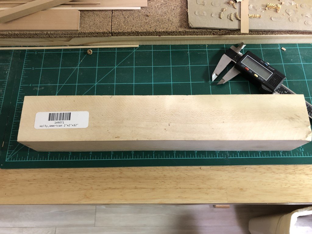
Here is what the cockpit floor looks like planked in holly: The pear, C box, and holly do look nice together! Received a new piece of holly today with no visible blueness - I hope its the same when I cut into it!
-
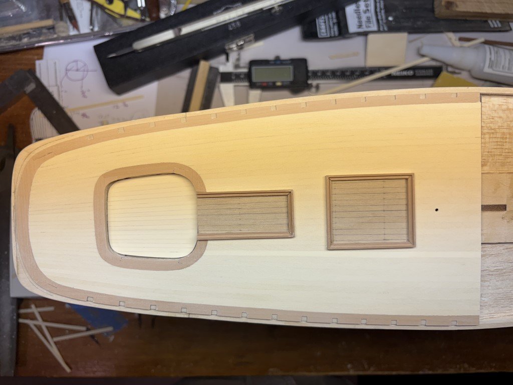
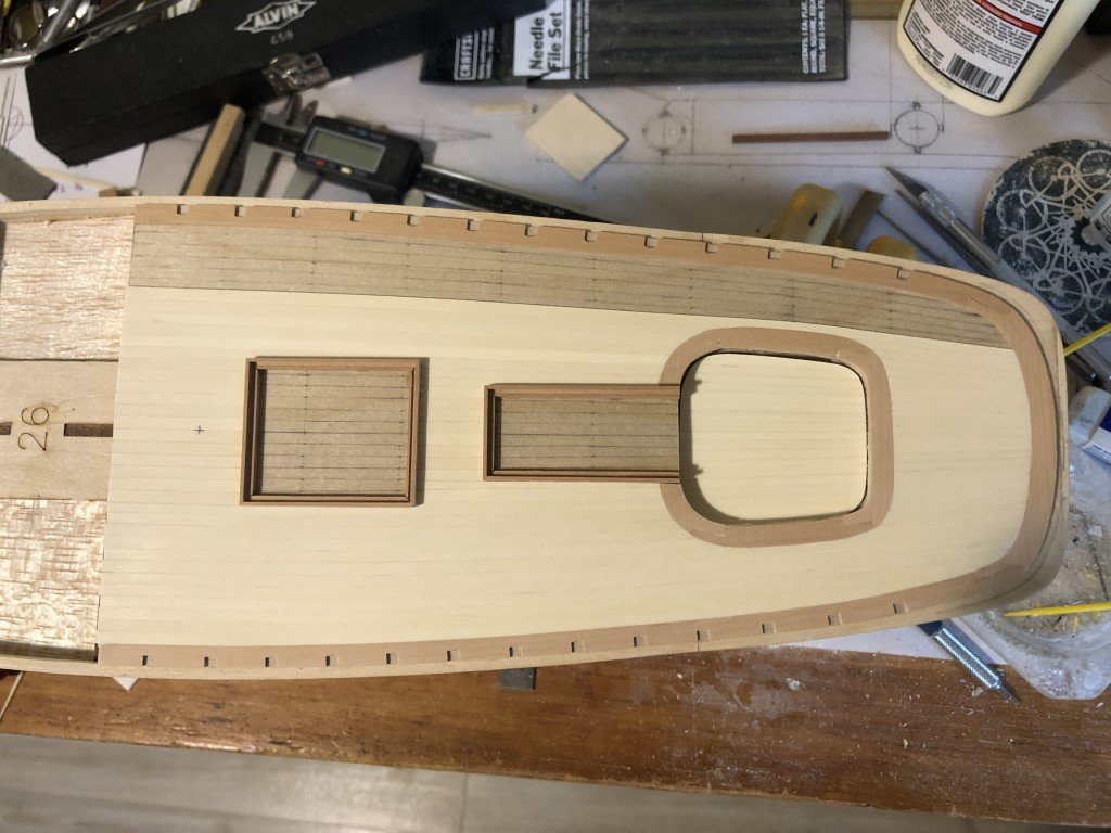
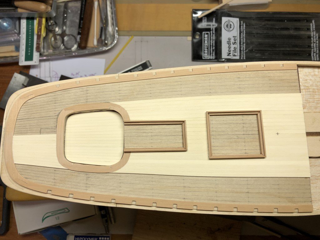
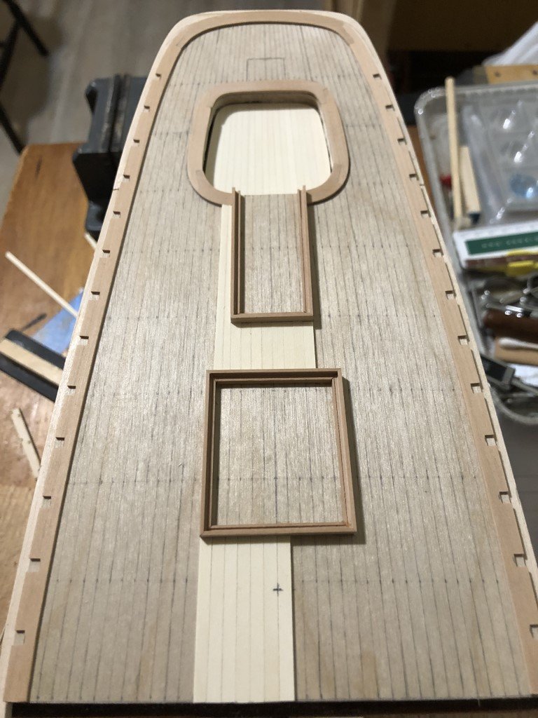
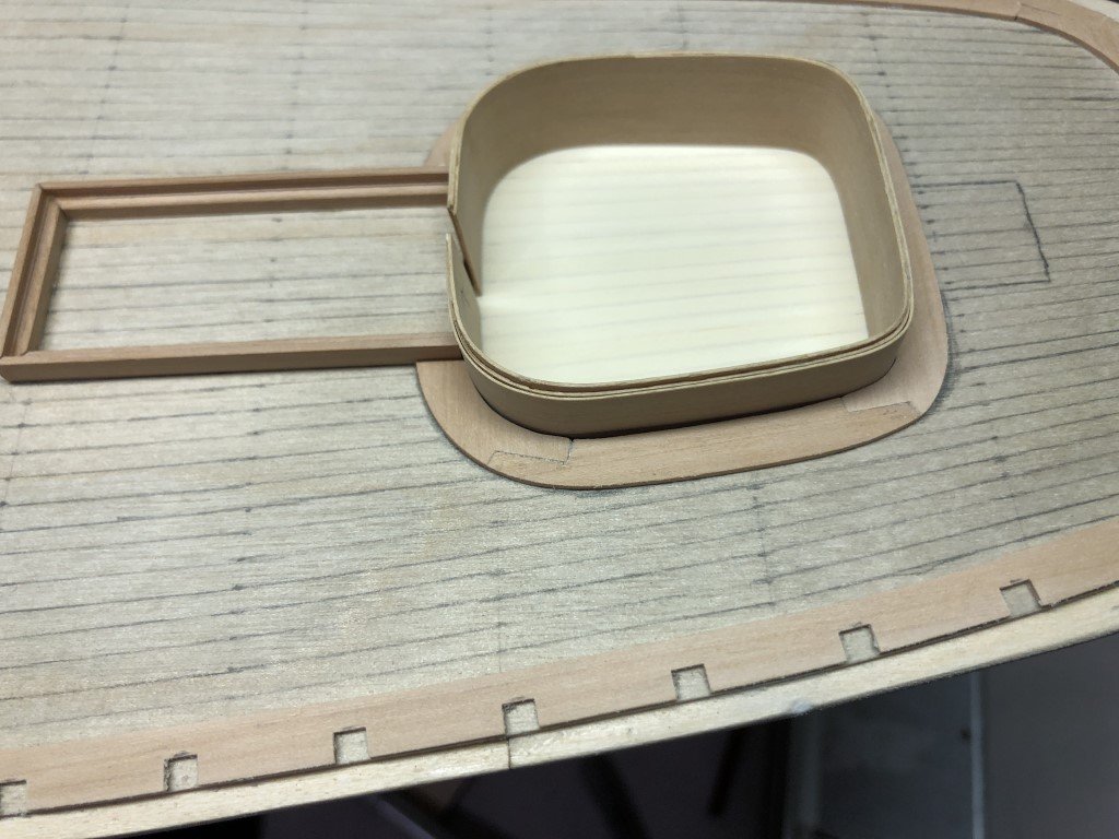
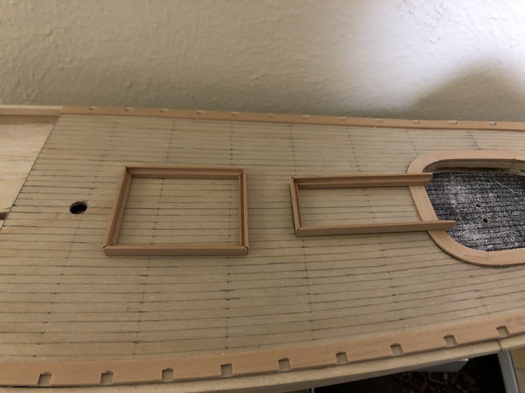
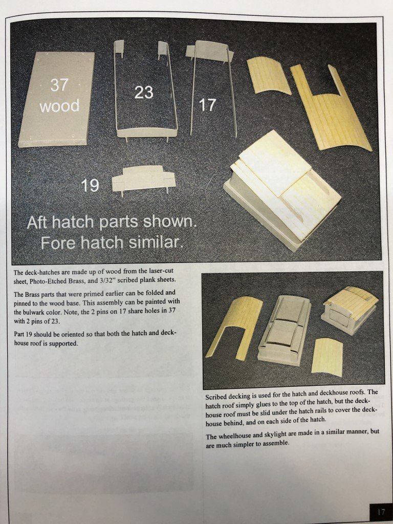
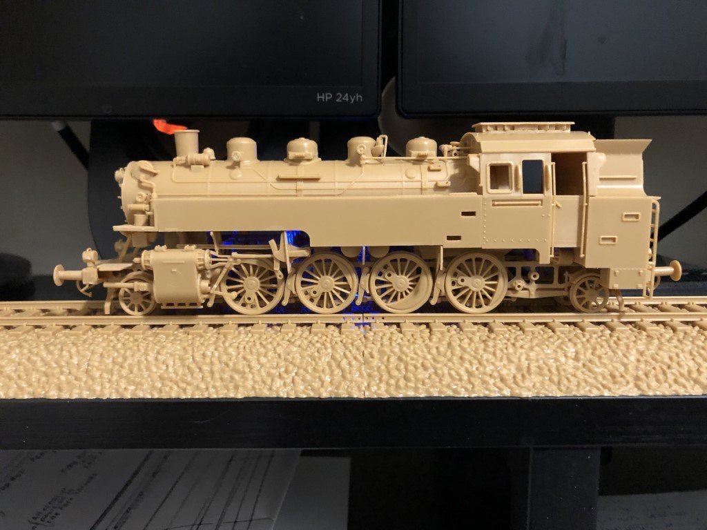
I milled some L-shaped pear to serve as hatch and skylight combings. They will be attached to the deck before I plank it. The material is 5/32" high, so once the deck is planked there will be a 1/8" high exterior border to the structures that is 1/32" thick. Scale-wise this would represent a 2" x 6" surround. I just went with a simple miter at the corners. Before attaching these pieces to the subdeck, there is a section of the cockpit margin board that needs to be cut away for the hatch combing to fit properly. I'll build the skylight and hatch off the model and drop them into the combing depressions. This should be an upgrade from the kit supplied materials and construction method. In fact, the construction method in the model baffles me - the sides of the structures are PE brass and use scribed plank sheets for the roofs. I'm confident that anyone that can plank this ship, copper the hull, mast and rig it, can build deck structures out of wood! So strange 🤔 The BR86 got some track to sit on. It is needed so that when the couplers can be added, they will not hit the ground as they drop down below the top of the rails. Ordered some paint for this machine - it will now sit for a few days as I await delivery.
-
Juhu Yes I hope the next batch is much better for being able to move along in the Phantom build (and also due to the price of holly). It is my plan to paint and copper the hull. But I don't want to use much paint at all other than that. I plan on the deck, inner bulwarks, deck furniture, and most of the masting to be natural wood color. I'll be doing what I can with different wood species to have some color changes on the model. For example, the deck houses and skylight will have C boxwood sides and pear edging - not sure yet on the roofs! I've gotten, or requested, replacement parts for wooden kits in the past. I only make a request when it is a part that I cannot remake on my own - typically a casting that is missing and/or partially formed. Typically, I haven't needed to pay shipping when the parts were sent to me. Sometimes it has been free, fast, and easy; sometimes free slow and hard; but the worst was a company that implied the parts would not have been missing and I was just trying to get extras for free. I looked at some videos and read some books to get some ideas on how to paint plastic model. Last time I built a plastic model was is in the early 70's and the high tech I used was painting parts still on the spur with a can of spray paint - a few steps past assemble the model and paint everything with a brush! But then I was barely a teenager. I think I've learned that making model kits is more of an adult thing even though the models where always placed in the kids area of the department stores. Yes, the painting skills of plastic modelers can be most impressive - besides the surface effects you mention, the ability to weather a model is incredible. When I paint the BR86, I'm going to be going for a closer to factory new look, than a well-used look!
-
In this situation, I am not interested in the 'bluish realism' - I want a white deck! So I am really hoping the piece of wood in the mail is a good one.