Greg Davis
-
Posts
807 -
Joined
-
Last visited
Content Type
Profiles
Forums
Gallery
Events
Everything posted by Greg Davis
-

BR-18 Locomotive by Greg Davis - OcCre - 1/32
Greg Davis replied to Greg Davis's topic in Non-ship/categorised builds
The boiler framing is all glued together and faired. I finally found a good use of a sanding 'tee bar' that I had from building model airplanes years ago. The fairing is minimal, but quite important so that the plating sits evenly along the boiler; however, the work is not as satisfying for me when it is compared to working on a ship's hull. Here the boiler is setting on a jig / stand that is included in the kit. First, it will be used to hold the boiler during the brass plating that comes next and then for adding castings / details. Later in the build, the stand is turned over and a couple of pieces are added to hold the lower mechanic of the engine.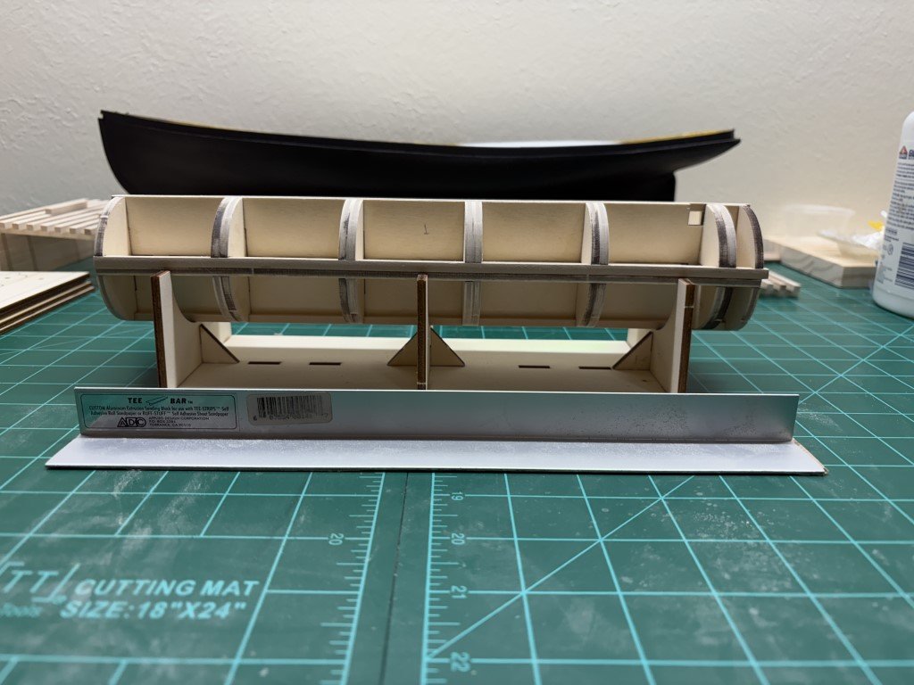
-
BR-18 Locomotive by Greg Davis - OcCre - 1/32
Greg Davis replied to Greg Davis's topic in Non-ship/categorised builds
Appreciate it! -
BR-18 Locomotive by Greg Davis - OcCre - 1/32
Greg Davis replied to Greg Davis's topic in Non-ship/categorised builds
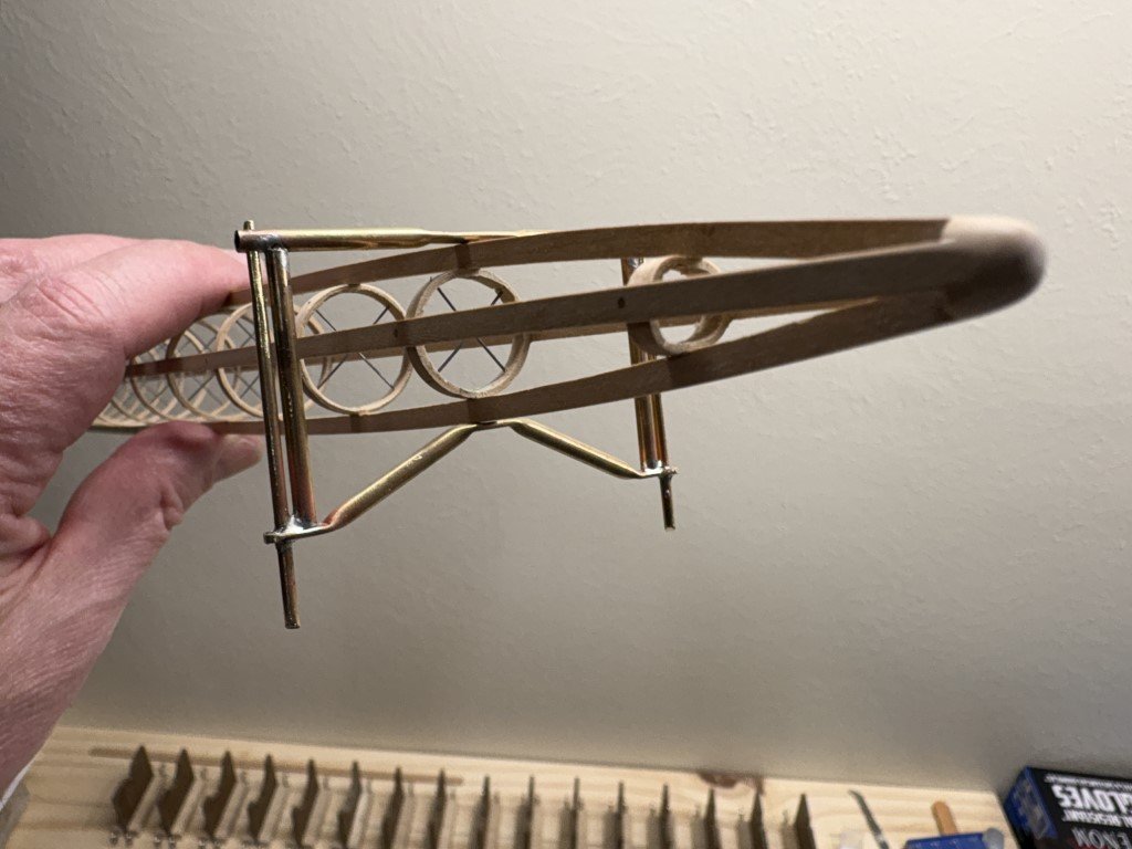
I've cut out and test fitted the 35 pieces of wood that serve as the boiler frame. Because I am so used to working with model ships, I will say that there are 7 bulkheads that mesh with a 4-piece false keel assembly. The 4 pieces in the false keel have tabs that interlock with one another along the central axis. This quickly squares up the bulkheads. There are then 4 stringers running fore to aft that slot in next to the false keel pieces. Finally the middle 5 bulkheads have doublers. Currently all these pieces are being held in place with clamps and rubber bands. Tomorrow I'll recheck that everything is in the correct place and then glue all of this together. Besides keeping everything square, I think the most important observation is that the doubles need to be placed on the aft side of the inner bulkheads. Looking ahead, the reason for all the doublers is that this structure will soon be covered with rectangular sheets of brass. The brass plates will line up with the center of the frames and doublers as well as the joint between keel pieces and stringers. If the doublers are placed on the wrong side of the bulkheads, there will not be correct support / fastening locations for the brass plates - hence I'm checking this tomorrow when I'm more awake! By the way, this boiler frame is 11.5" long and 2.375" in diameter!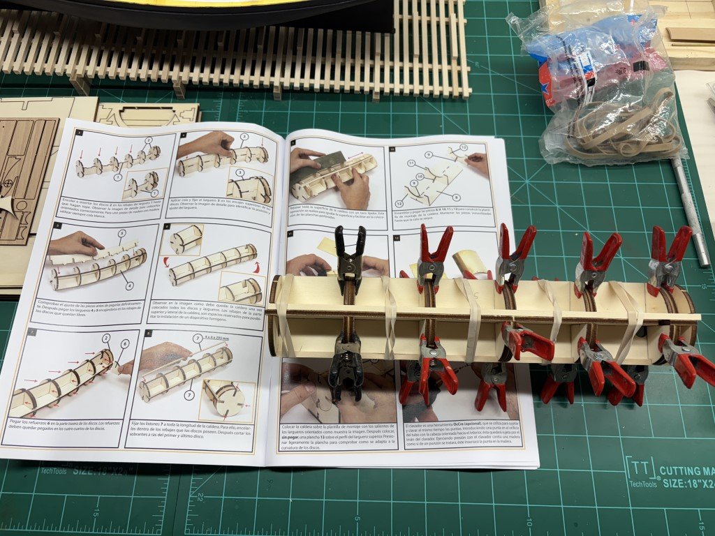
- 33 replies
-
- 10
-

-

-
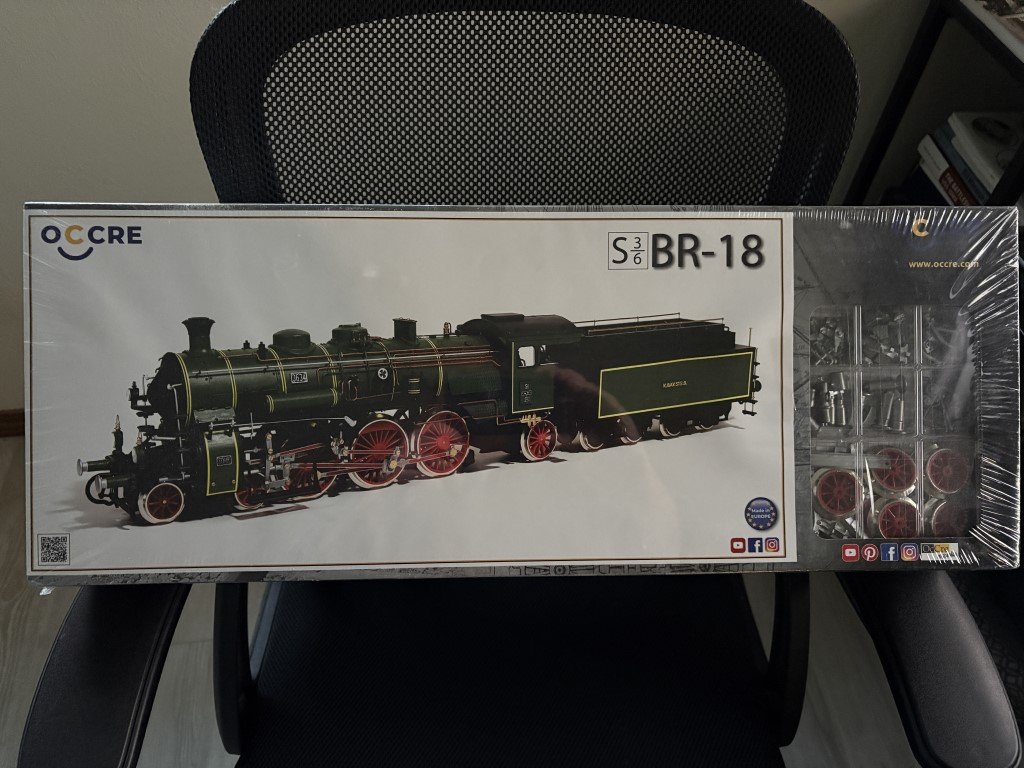
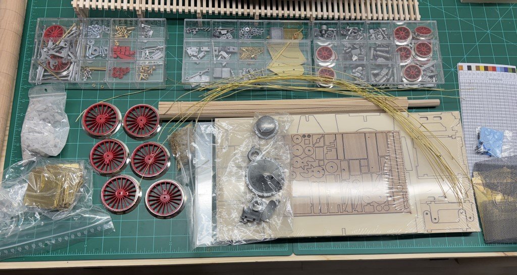
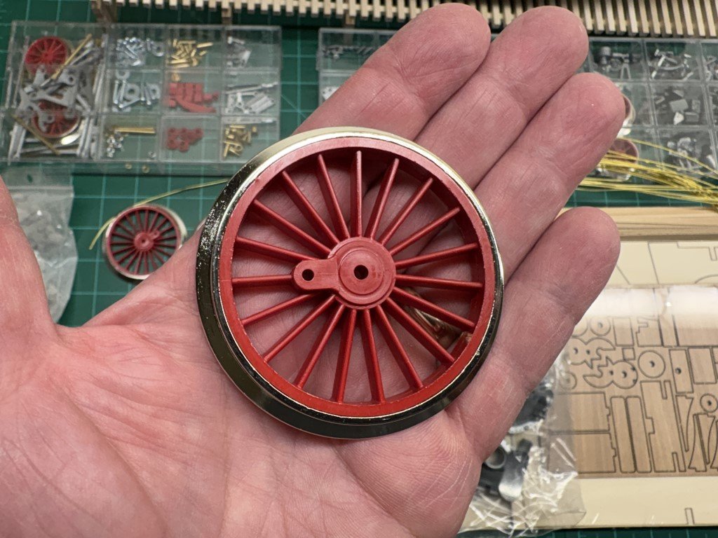
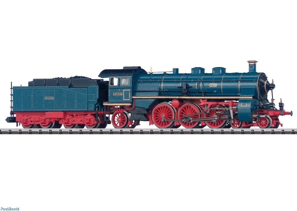
Today I couldn't overcome the need to start yet another project - this time the 1/32 scale BR-18 Locomotive kit made by OcCre. This is a model that I have had my eye on for many years, but was unsure about paying the list price for. When Model Expo was closing out their line of OcCre products, I was able to get it for 50% list - so it was added to the massive stash. OcCre considers this an advanced level model that should take approximately 500 hours to complete. They also indicate that the model has 2342 parts - thus the model should be assembled at the rate of 4.684 parts / hour. When the box arrived I did notice that it was quite heavy and after opening it is clear why that is the case - the model is dominated by metal parts! There is a lot of brass and a ton of soft metal castings. I was impressed by the size of the drive wheels - 3 5/8" in diameter - this is going to be a good size model when completed! While the box cover art and instructions make the model up in a very nice green and gold theme (that actually works good for a Green Bay Packers fan), I plan on going with a blue based theme similar to this Marklin BR18: I am looking forward to diving into the model immediately with the project sharing time with at least three others!
- 33 replies
-
- 12
-
-
-
I think you noticed the key to what happened - I've stared at these pictures countless hours and never noticed the change in the platform location! I wonder if after some trials, SD found that the rear end was not staying down enough so the platform was moved back to provide additional leverage. I'm now planning going forward to leave / position the rear hydrofoil on the second to last hoop and keep the the platform in the pushed back location. Thank you so much for sharing your observation. Greg
- 288 replies
-
- 5
-
-
- Santos Dumont No. 18
- hydroplane
- (and 1 more)
-
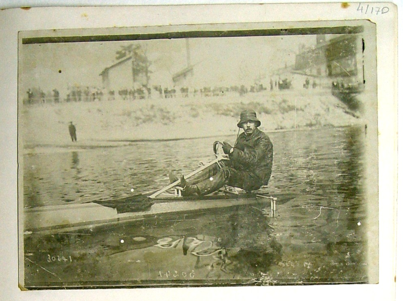
I don't think there was a prototype as much as the No 18 Hydroplane was a 'work in progress', it seems to have been the case that Santos-Dumont modified many of his creations as they were built and tested. The top picture that Craig posted was taken earlier than the bottom picture. The top picture is a reflection of this photograph (Henrique Lins de Barros sent me copies of some original pictures of the boat): At this time the engine had not been attached to the boat. The second picture was taken later when the engine was in place and the boat was essentially complete. A couple changes are noticeable between the two pictures, the covering of the pontoon has changes from one that has longitudinal stripes to being a solid color. Another, functional, change is that there is a lever in Santos-Dumont's right hand in the early picture - I have assumed this was to be a throttle; in the second picture the lever is missing and additional controls are now connected to the steering wheel. For me, it is hard to say if the steering column has been changed because the pictures are taken from different angles. The steering wheel looks to have similar height wrt his chest. S-D's leg looks straighter in the second picture, but this could also be from moving the saddle back a bit without moving the platform. Since my model is to have the engine, my work should better approximate the later photograph. It's hard for me to work this one out as I feel (without photographic evidence) the rear hydrofoil structure should mount at a hoop location as this would minimize the number of holes / bolts needed to hold the craft together and maximize its strength. If I follow this line of thought, I should attach to one of the last two hoops - the second to last may be a bit to forward, but the last one I have might be to far back. The other options would be to attach just to the stringers between the last two hoops and/or add another hoop between them for attachment purposes. I'm not really fond of those solutions because it ruins some of the symmetry in the model. I really appreciate the feedback and advice that all of you are providing and I hope it will help lead me to a satisfactory solution to the rear hydrofoil and cockpit locations. Thanks to all of you!
- 288 replies
-
- 4
-
-
- Santos Dumont No. 18
- hydroplane
- (and 1 more)
-
After some additional reflection and looking at pictures of the rear end, now I'm not sure it needs to be moved and I may have actually drawn it too far aft in my building plans.
- 288 replies
-
- 2
-
-
- Santos Dumont No. 18
- hydroplane
- (and 1 more)
-
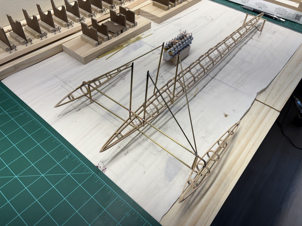
Today I did test fitting of the pontoon / nacelle harness and engine pylon structure. It went fairly well, I just needed to make a small adjustment on the location of the front engine supports - they needed to come down about 1/16" from where they were originally attached. While doing the test fit, I noticed I made a mistake on the rear hydrofoil mounting structure. I fit the structure to the second to last hoop location - it should be placed at the furthest back hoop. So I am going to need to rebuild the lower portion of the structure! I'll go back to working on the engine in a while. Still needing to do some research / determination as to how the coolant and fuel systems were set up. I won't be able to model all the details, but I do want what I do put in being fundamentally correct.
- 288 replies
-
- 7
-
-
-
- Santos Dumont No. 18
- hydroplane
- (and 1 more)
-
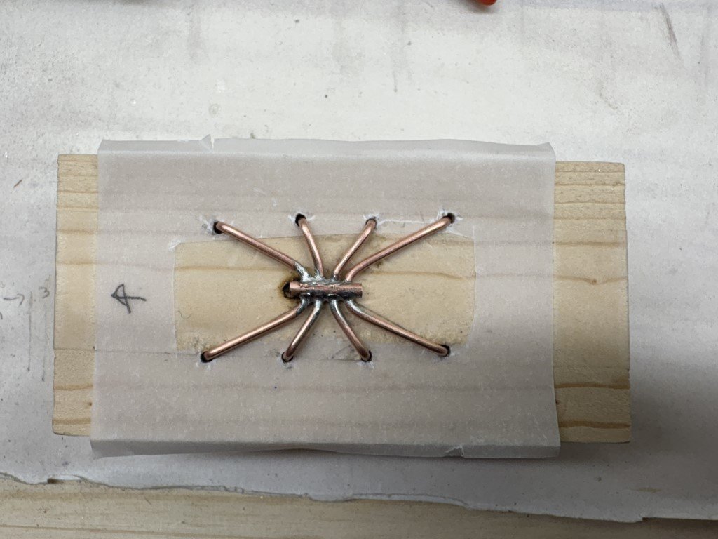
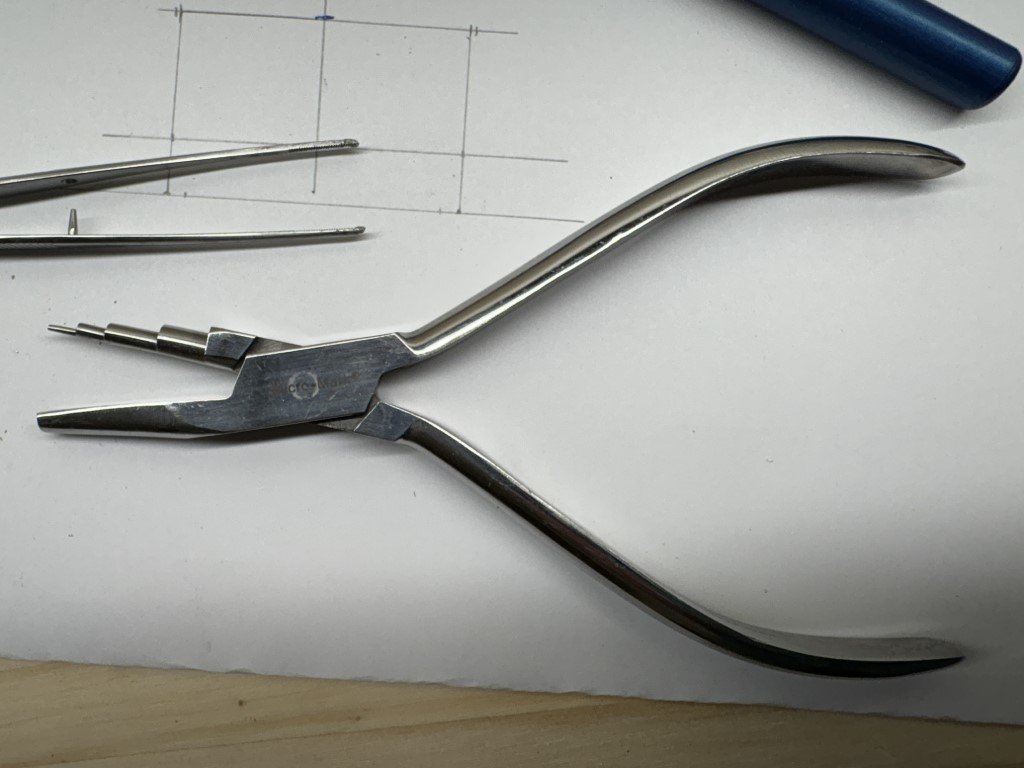
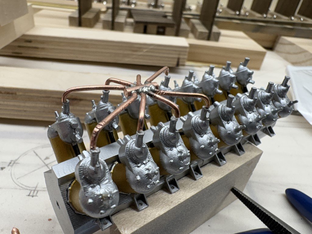
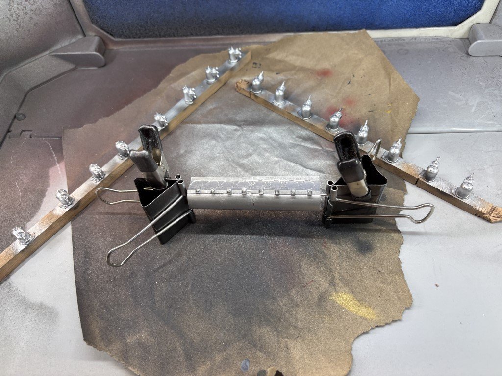
It took 5 tries, but now I have 2 intake manifolds that can be used on the model: There is a small amount of final adjustments that need to be made, but that should be easy since the copper bends nicely. The basic alignment of the pipes were made using a jig I had made for my Santos-Dumont 14bis model - I'm glad I didn't throw it away after finishing the kit! The central piece is 12 gauge copper. Four holes were drilled through the cylinder to accept 18 gauge copper that form the distribution pipes. The four sets of pipes were soldered before bending to shape. Two 3/32" rods were slid under the 'spider' to lift it out of the jig and the pipes were snipped off flush with the jig. The ends will be smoothed out when the final fitting / attachment to the cylinder castings is done. Need to keep these safe until then!
- 288 replies
-
- 9
-
-
-
- Santos Dumont No. 18
- hydroplane
- (and 1 more)
-
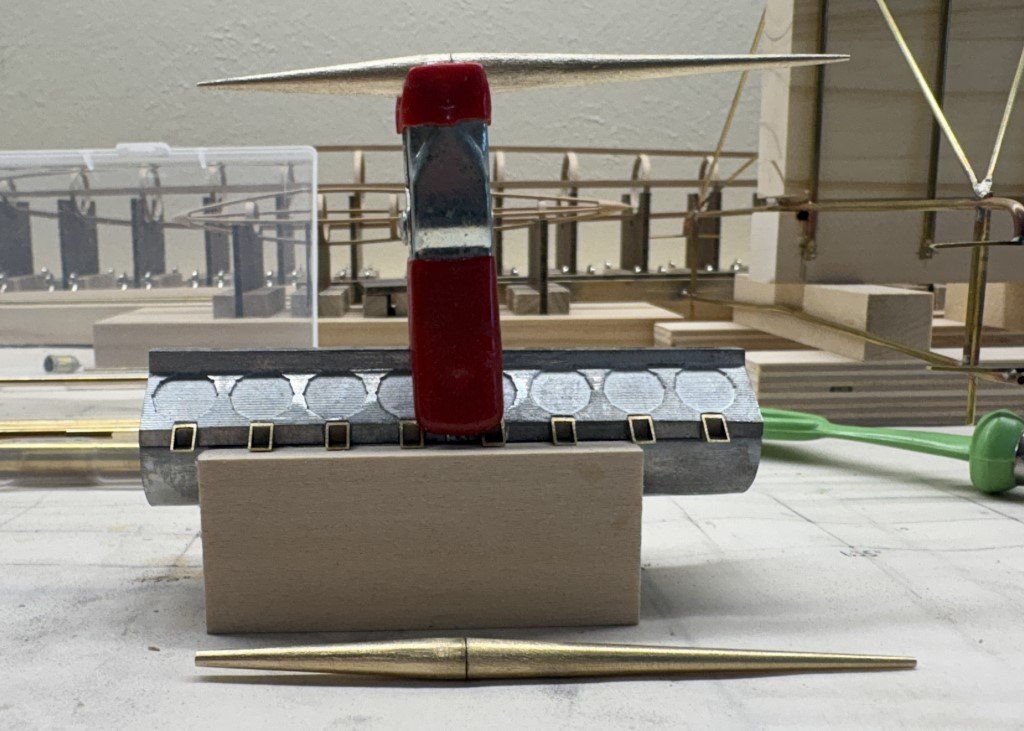
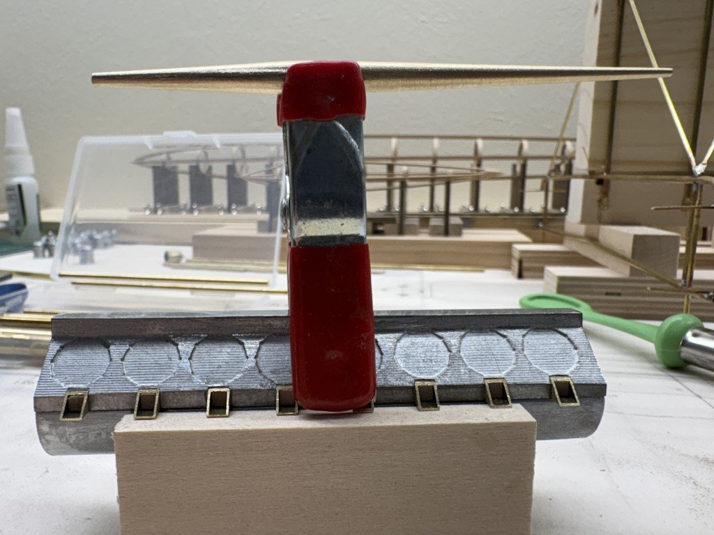
Plenty more to work on while pondering the fueling system! So some different metal work; its the mounting structure for the rear hydrofoil: I feel that I am getting close to being able to tie the main components, less the engine, all together.
- 288 replies
-
- 9
-
-
- Santos Dumont No. 18
- hydroplane
- (and 1 more)
-
Not sure - the copper might not be stiff enough to hold the bend when pulled back out of the tubing bender.
- 288 replies
-
- 2
-
-
- Santos Dumont No. 18
- hydroplane
- (and 1 more)
-
this is dead soft copper, so it bends very easily - to easily in some cases, I believe that is why it damages with little effort. Next I'm going to redo the work using a rod like you suggest. I had used looping pliers for the first try. The wire notched where it contacted the lower edges of the tool. Some of the nylon faced jewelry equipment might work better with this material.
- 288 replies
-
- 3
-
-
- Santos Dumont No. 18
- hydroplane
- (and 1 more)
-
But I know where they are and if I don't address them it will bother me for ever! This is not to say that there may be (are) other imperfections that will stay - but some I can live with and others I can't.
-
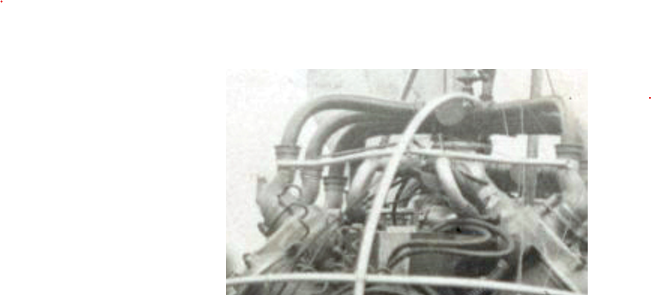
This is my first try at making the fuel distribution system - two copies are needed. I drilled 4 holes through the center copper piece, soldered and then bent the distribution pipes. I think I can improve on this trial a bit, but most importantly, I hope that it looks a bit more like what was on the hydroplane than the castings that came with the engine kits (see pic of the V8 from my 14bis build below). The copper seems to be about the right diameters, but the bends need to be done without so much damage to the wire.
- 288 replies
-
- 11
-
-
- Santos Dumont No. 18
- hydroplane
- (and 1 more)
-
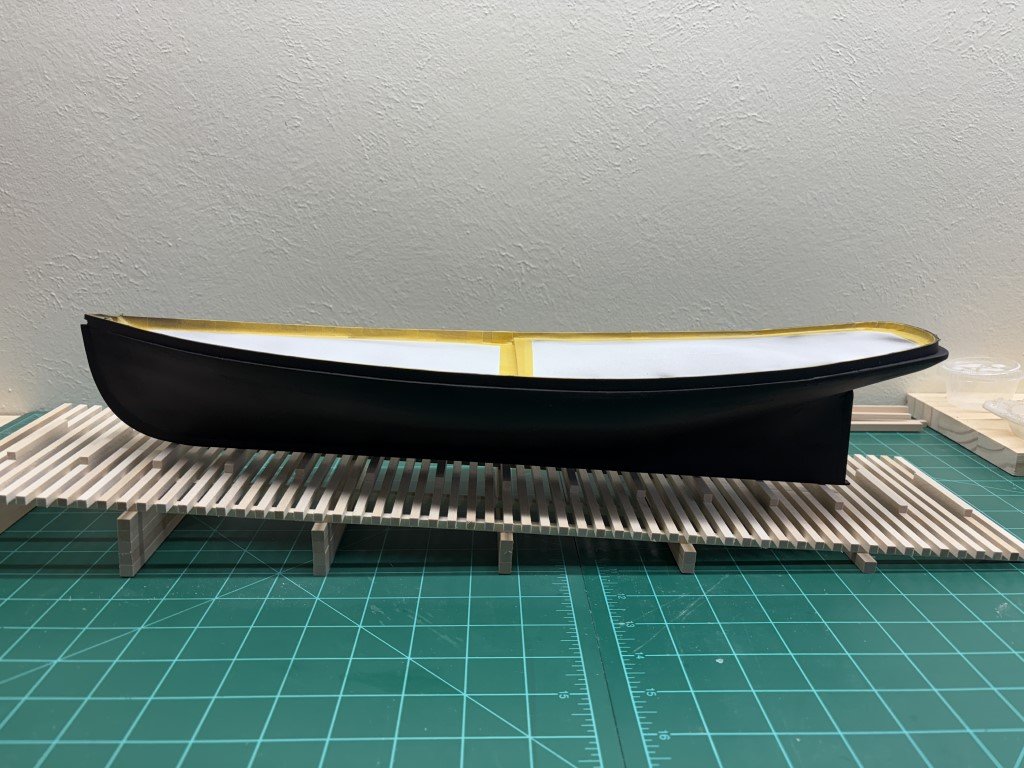
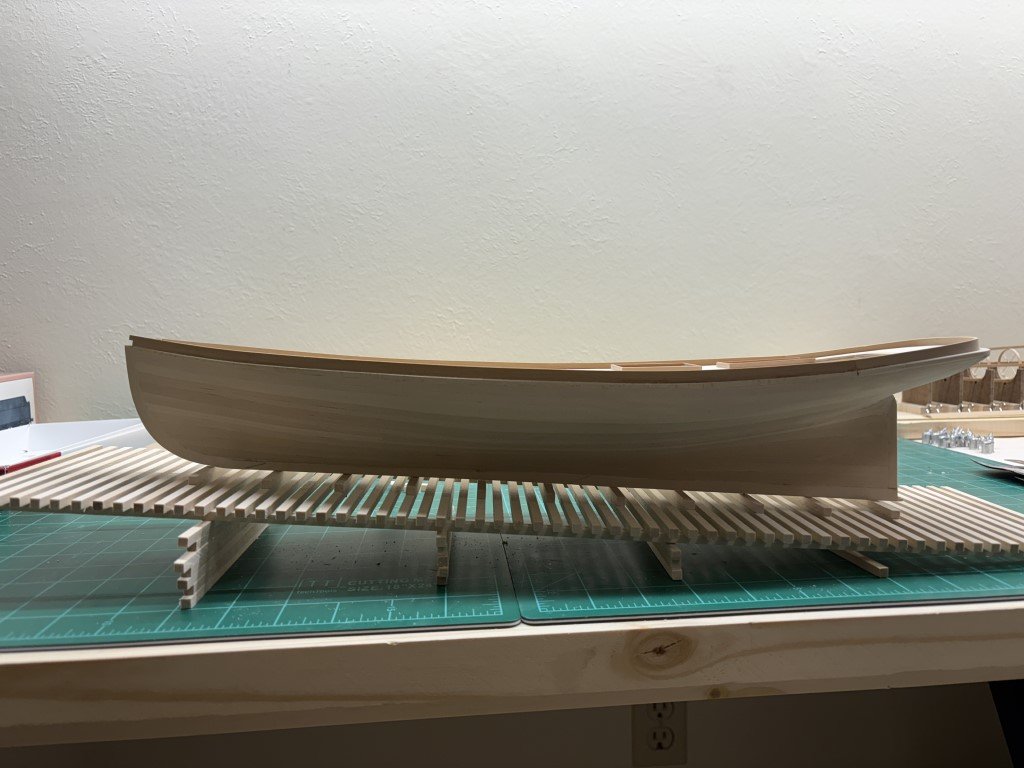
I've spayed the hull several times with black paint. I thought it was ready to varnish, but upon closer inspection, I found two locations where the paint could be smoother. So I am going to sand those regions a bit and recoat before moving on. As you would guess, the areas that need attention are above the water line - everything below, where the copper will go is just fine!
-
Keith - I really appreciate the support from you and everyone else following this adventure! Greg
- 288 replies
-
- 2
-
-
- Santos Dumont No. 18
- hydroplane
- (and 1 more)
-
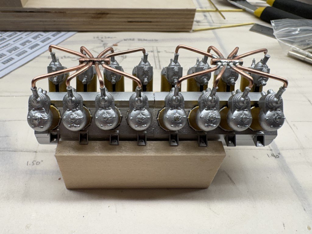
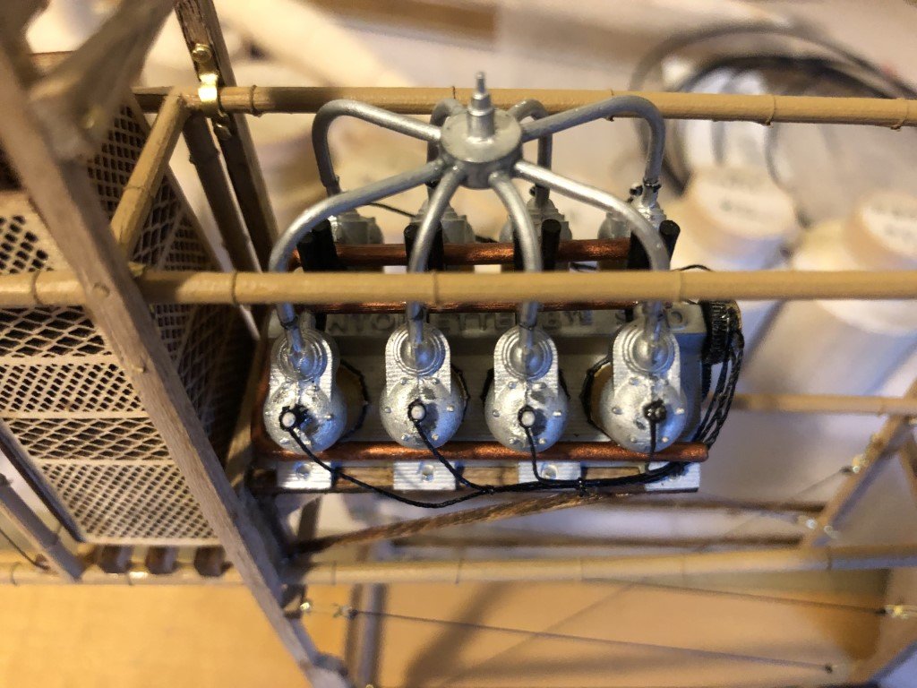
The remaining painting of the cylinders was completed and now they are attached to the engine block. It is really starting to grow (and get heavy). I think the fueling system needs to be worked out next.
- 288 replies
-
- 9
-
-
-
- Santos Dumont No. 18
- hydroplane
- (and 1 more)
-
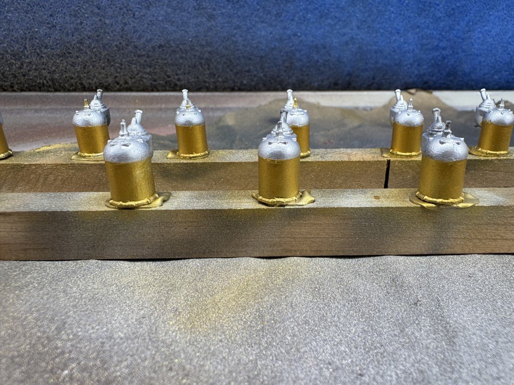
The water jackets have been painted brass (not copper as I mistaken mentioned in the previous post). AON - thanks again for having me reconsider painting the castings! The bases will be repainted aluminum and then I'll install the castings on the engine block.
- 288 replies
-
- 4
-

-
-
- Santos Dumont No. 18
- hydroplane
- (and 1 more)
-
A couple of days ago I primed the engine block and cylinders a dark grey. Today they got a coat of aluminum. In another couple of days I will add the copper color to the cylinder castings. Not sure if the paint will need to be toned down a bit with a wash. I'll better know after the engine is assembled. Since the model is open framed, I would like the engine to be relatively clean.
- 288 replies
-
- 8
-
-
- Santos Dumont No. 18
- hydroplane
- (and 1 more)
-
The hull was primed a dark grey yesterday - tomorrow I can paint it black!
-
New, larger fuel tank - this one 'looks' correct compared to the historical pictures. Once it is polished up, it should be a keeper!
- 288 replies
-
- 8
-
-
- Santos Dumont No. 18
- hydroplane
- (and 1 more)
-
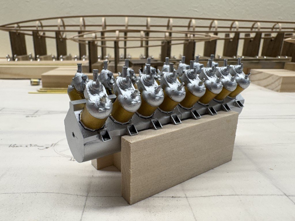
Reduced the length of the crankcase castings to match the length of the upper portion of the engine. After cleaning up the result, it was attached to the top of the engine casing. I filled the brass tubes so that you can no longer see thru the engine! Made my first attempt on the fuel tank. This one is made from 5mm brass rods - the two cones are pinned with a 1/16" brass rod. I had taken measurements from pictures of the hydroplane and the 5mm (scale) diameter seemed reasonable, but I think I'm going to remake the tank with 6mm rods as this looks a little slim to me. I also did a bit of looking around on the web and found that an Antoinette V8 consumed fuel at 30L/hr. Assuming the V16 consumes twice that, i.e., 60L/hr or 1L/min, the tank I made would hold 10L of fuel or about 10min of run time. While it might be possible to do the two 1K passages at 100Km/hr in 10 minutes, it probably would be cutting things close. Moving to a 6mm tank (same length) the volume increases to a full size tank holding 15L (15min run time). I can see how the boat could be started, run a kilometer, turned and run back in that time frame. So, the current tank is probably just practice!
- 288 replies
-
- 10
-
-
- Santos Dumont No. 18
- hydroplane
- (and 1 more)
-
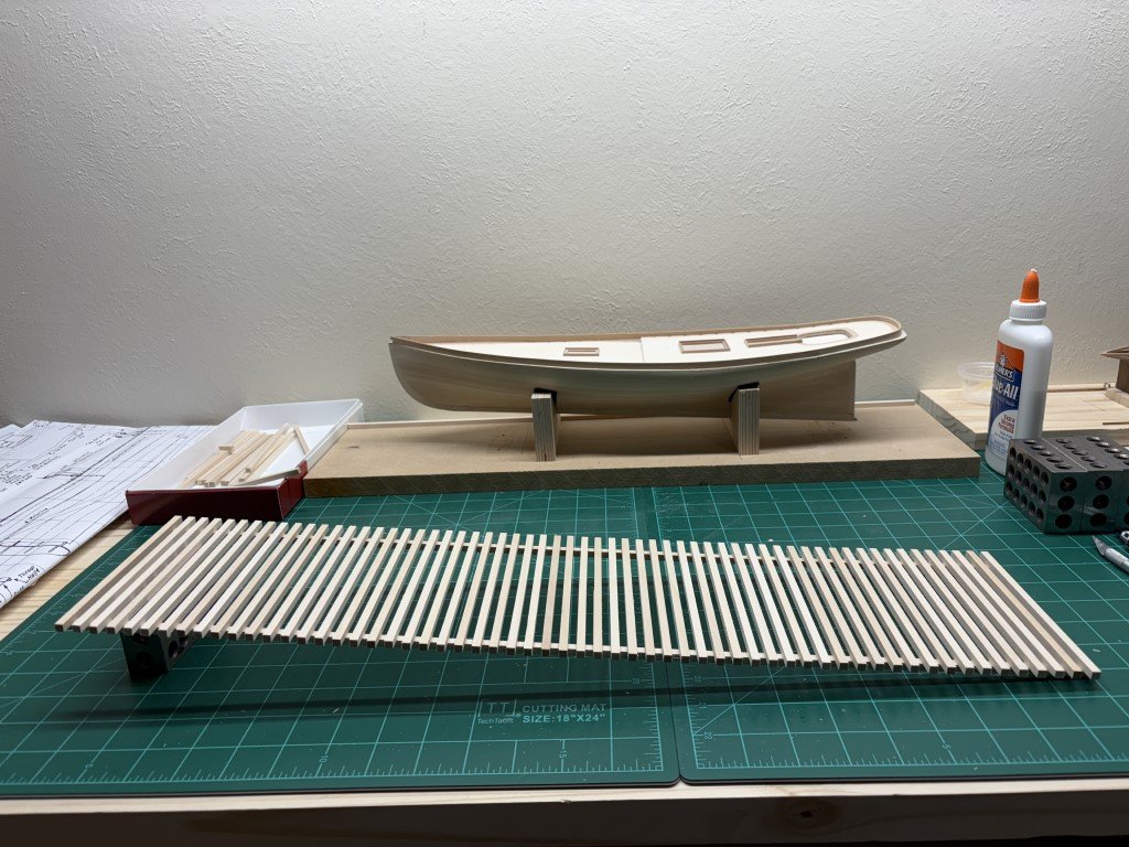
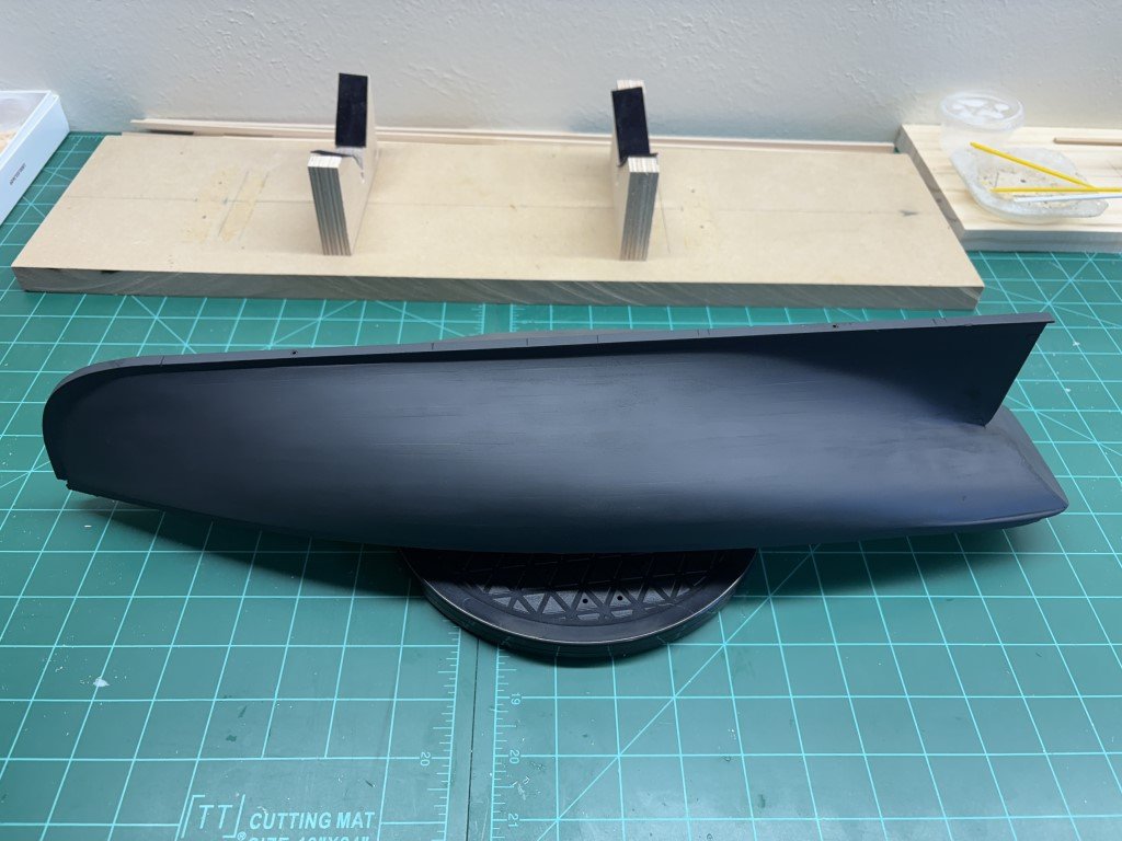
Here is the Phantom hull sitting (attached to) on the slipway at approximately the correct angle. The slipway risers need a bit of adjustment / finalization as to where I want them to be.
-
Here is the top of the slipway in its finished state. I had gone to Seattle for a few days and hoped that all the slats would have been in place when I returned; however, the slipway fairy clearly did not show up - so about 50 copies of the same strip over the last day or so! Next step is to get this sloping to just the right angle so the hull can be mounted and the waterline can be drawn to match.