Greg Davis
-
Posts
807 -
Joined
-
Last visited
Content Type
Profiles
Forums
Gallery
Events
Everything posted by Greg Davis
-
 I'm hoping to work more on Phantom this evening, but wanted to post a picture of the BR86 after 7 days of work. There is very little I can now add prior to painting. Currently, the model disassembles into 7 subassemblies and all the drive wheels come off (which is good since the second from front needs to be in the third position when the model is completed).
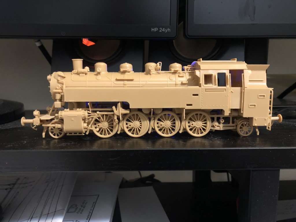
-
I have ordered another piece of holly from a different company. Hopefully it will generate cleaner strips of wood for the decking. I would like the deck to be the nice white color. Interestingly, I have read posts that the authors claim leaving some of the blue hue in the planks increases the realism of a model.
-
Today I milled some of the holly. You may have noticed some discoloration of the holly in the picture posted previously. Unfortunately, this blueness became more prominent when I made some 1mm thick sheets of the wood: I'm not quite sure what to do now. I read that there may be a chance that the color can be bleached out with a wood bleach. I could try to work with the whiter parts of the wood and hope that the blue does not spread - or I could rethink the planking opportunities. So I cut a few strips of the holly, as well as some from the maple and C boxwood that I had milled earlier. The strips where set on Phantom with hopes of picking the wood spieces to continue on with. Holly: Maple - the two types from before separated Maple - two types mixed Maple / Holly comparison Maple / Holly / C Box comparison I think the holly has the nicest contrast with the pear, and has a similar grain like the C boxwood and pear; the C Box seems to be blending in with the pear, and the maple has a nice color but the grain seems out of place. Supposing the holly is picked does anyone have any idea if what is presently white will remain white if I remove / don't use the blueish portions of the wood?


-
Fore mast is round - needs to be shortened 1" from the top to bring it to the final needed dimensions: The board below the model is the holly I ordered. It is 7/8" thick so it can be sliced a few times and will yield more than enough decking material. I'm looking forward to work with a wood species that is new to me. Presently, I am trying to decide if I should place combings for the deck structures in place before or after planking the deck - going to need to finalize the working plan soon! A bit more progress on the BR86 as well - it now has a coal bunker. Not much more can be done before starting the painting process.


-
Dave - To my knowledge the 1/8 scale plans (which are the same as the 1/4 plans) represent a reconstruction of the Phantom by George Campbell. According to the instruction booklet, the deck details and rigging are based on photo information from the Peabody Museum - but there is no indication if this information is actual pictures of Phantom or if it is based on ships from the same period. While I would really like to, I have never seen a photograph of the actual ship. Since the ship is often modeled and photos are not shown, my guess is they do not exist. The instructions indicate the hull lines are based on the work of Howard Chapelle and are taken from a builder's half-model (no clue if there was any specific deck info). How the lines came about is noted in Chapelle's 'History of American Sailing Ships' and the lines are published there - but no planking details are discussed. Chapelle writes about pilot boats in a number of his books - e.g., American Sailing Craft, The Baltimore Clipper, Fishing Schooners - however in none of these books do I find deck planking details related to cockpits. It seems to me that in many of his writings, the emphasis is on hull design and rig. Interestingly, there is a clue that such margins could have been used is found in Chapelle's book 'Boatbuilding'. Within the book is an illustration of a margin plank along a combing, the mast bed, and a king plank on a ship where the deck planks follow the exterior curvature; i.e., in the manner the aft deck is to be planked on the Phantom model. In fact he writes " The hatches may require nibbing pieces, or 'margins', which will avoid feather, or shim, ends in the planking, when cut to form the hatch opening, in a deck laid with the side of the hull. Or, if the deck is laid straight, and there is a slight sweep to the sides of the cabin truck and cockpit, it may be desirable to fit a wide plank to serve the same purpose as a margin." To me, this does give justification to place a margin board around the cockpit on Phantom - but of course it is conjectural. Personally, I liked what Victory78 / Davies had done in adding the margin plank about the cockpit and I have then done the same. Greg P.S. Good to hear from a fellow Wisconsinite!
-
Ian - That is good to know. Thank you Greg
-
The order I made for Holly to plank the deck is set to arrive tomorrow evening - I'm looking forward to seeing what the piece of wood looks like! I've now tapered square and then planed to an octagonal cross-section the fore-mast. The work is going smoothly as it did on the main mast. This one is just a bit longer. I'm hoping that I will have time to sand the mast round and to its final dimensions tomorrow. Work also continues on the BR86 - here is what it looks like on Day 4: Assembling this kit is quite different for me - every step of the way, I'm concerned about breaking one of the fragile parts and not having a good way to fabricate a replacement. I no longer have this issue with the wooden ship models; here I've got the perspective that if something breaks I can rebuild it to the same or higher standard. Is this possible in plastic kit construction / is the builder always in a 'don't break that' mode?


-
Took a day off from Phantom and for a change of pace started my first plastic model since middle school. The is how far I got on the HobbyBoss 1/72 BR86 kit. Trying real hard to get use to Tamiya cement - absolutely no experience with brushed on cement. Overall, it is enjoyable, but so different than working on the wooden ship models. Here I feel that I am in an assembly mode with little / no fabrication. Such a different skill set - and I'm am just starting to think about the paint application that will probably be a much bigger effort for me in order to just get a 'presentable' outcome. I am simply amazed with what some individuals can do in terms of realism.

-
Yep - could have put them on, to be perfectly truthful I forgot!
-
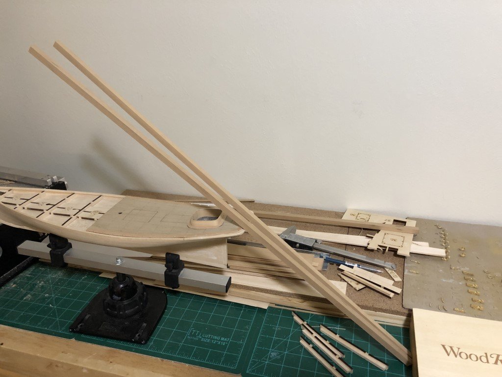
The sanding process did not take too long either. So the close to 17" main mast tapering from 5/16" to 3/16" in a parabolic fashion is now round (and straight!): I still have excess material on both ends that needs to be removed. Also, the very top needs to be squared for the cap - but material has been left for that operation as well. Some good news also: I received an e-mail notifying me that the holly I ordered has shipped on should get to me by the middle of next week. So maybe some deck work coming soon?!

-
In the past, I've always 'turned' my masts - either using a lathe or the drill method. When I first started building, I would use dowels for masts. I number of builds ago, I started to work from squared stock that I would often taper before spinning the wood inside of sandpaper. That is not to say I haven't been aware of the method where you start with squared material, taper, then change to an octagonal cross section (or even a 16 sided regular polygon in cross section) before sanding to final shape. This method has looked hard - but I decided to give it a go with this model, partially due to the long / relatively slim nature of the masts. While having quite a few references to the method, this time I pulled out a copy of David Antscherl's 'The Fully Framed Model, Volume IV' that is dedicated to masting and rigging. Here I mimicked his jig for holding the mast in place as it is worked. I also made use of the 7-10-7 template PDF that Chuck Passaro shared on MSW. So with the squared C boxwood in hand, I drew the mast shape on one side of the blank and used my oscillating sanded to sand two sides of the blank. The same profile was drawn on one of the now shaped sides so the remaining two sides could be sanded. Then I used the 7-10-7 template to mark what needed to be planed in order to change the cross-section to an octagon. I put the blank in the jig and first tried to reduce the material with a chisel as described by Antscherl, but found that I was a bit more handy with a razor plane. It took hardly anytime to plane off the edges and now I am ready to sand the mast round. This was fast, efficient, made much less of a mess and was dramatically faster. I don't think I'll go back to using the drill / lathe as a starting point again! I might also note that Antscherl teaches this method in the Model Shipways Shipwright series of models - probably a much better place for a beginner than this 'beginner' model of Phantom.


-
Among other things is that eventually a couple of masts will be needed! Today I formed two 3/8" square C boxwood trips to serve as blanks for the lower portions of the main and fore masts. Here is a place where the kit, specifically the plans and instructions, needs to be expanded in terms of information that should be included - especially since this model is being marketed as one for 'beginners'. I don't have any problem at all with dowels being supplied for the masts - and the supplied ones are not terrible. I just wanted something a little nicer for my model. However, it would have been a good thing if there were seperate drawings of the masts. Instead one needs to look at the profile drawing where the mast disappears at the top rail. This leaves the modeler with determining the additional distance to the deck - but maybe more importantly, the instructions do not tell the modeler to make allowance for the distance the mast steps into the false-keel. I have a feeling that there are goi9ng to be a number of these Phantom models made with shorter than expected masts! Anyway, here's the blanks, currently they are a few inches longer than what will be needed.
-
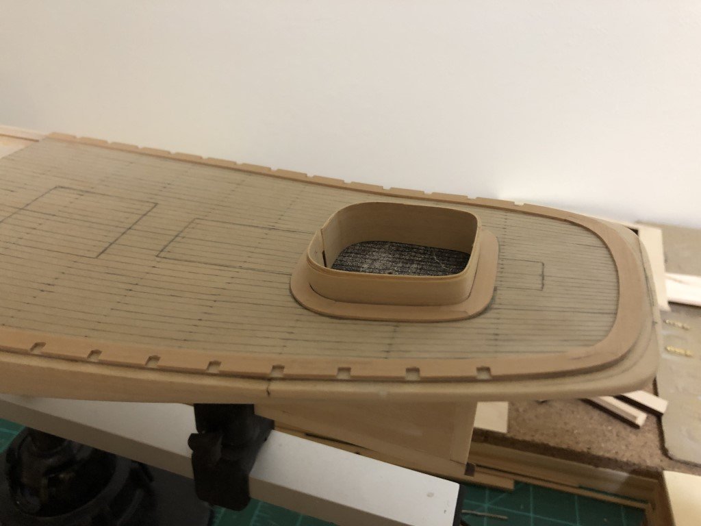
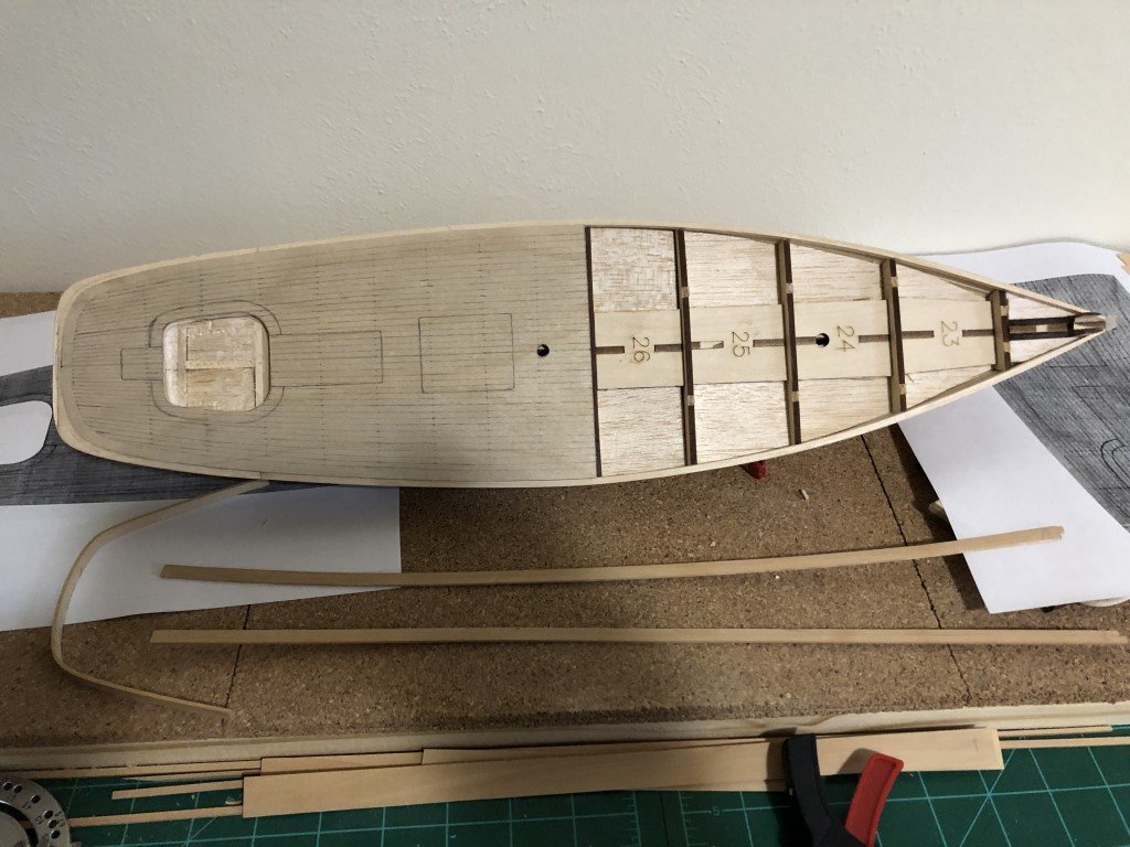
Yesterday / today spent time making and fitting a margin plank around the exterior of the cockpit bulwark. It was made from 4 pieces of swiss pear - not quite as fancy as the one on the Volk, Davies model, but a nice addition. I did order some holly as possible decking material. Not sure how long it will be before it shows up. While I wait there certainly are other things that can be done on the model!
-
Thank you so much for the positive comments! I also have lots of projects that I should finish - but I still had to have this one. Greg
-
The cockpit bulwark is out of the mold and fits nicely! The top will need to be trimmed down to the final height later. Space will also need to be made on the fore side where the cabin fits in.
-
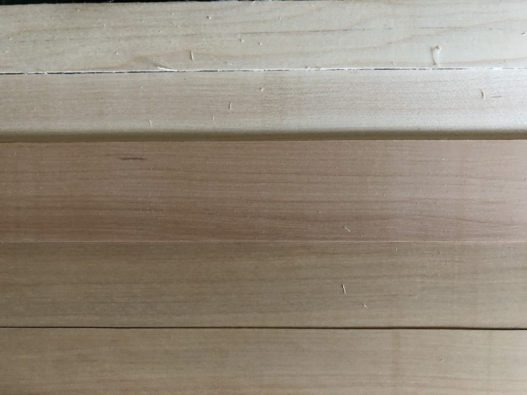
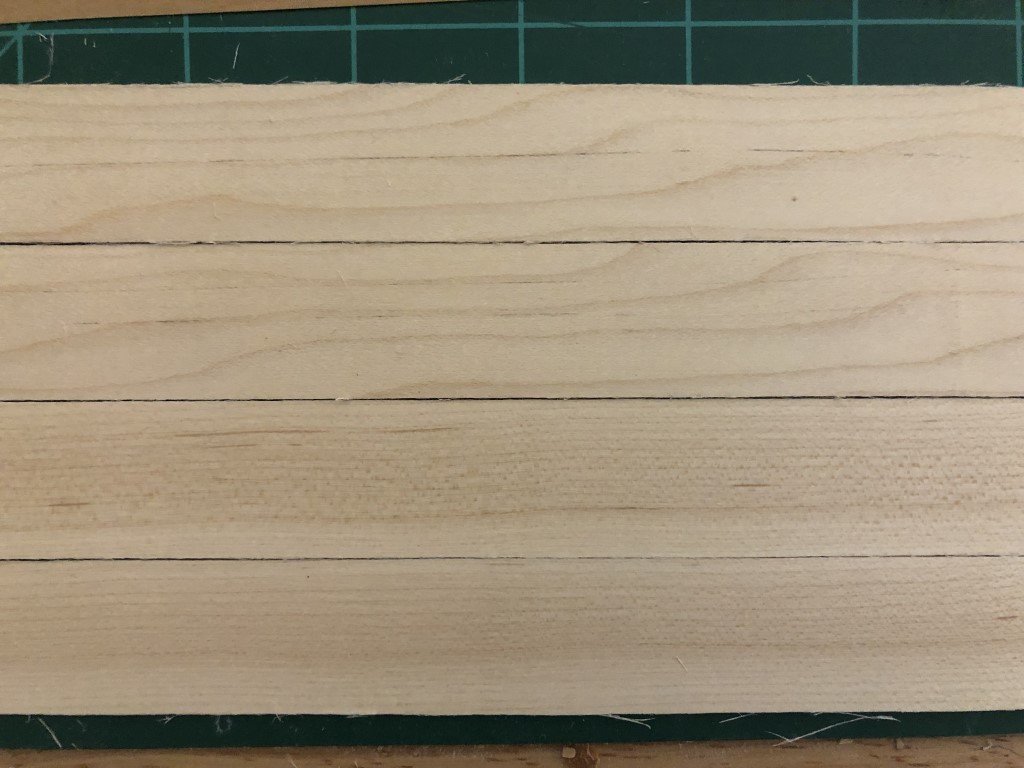
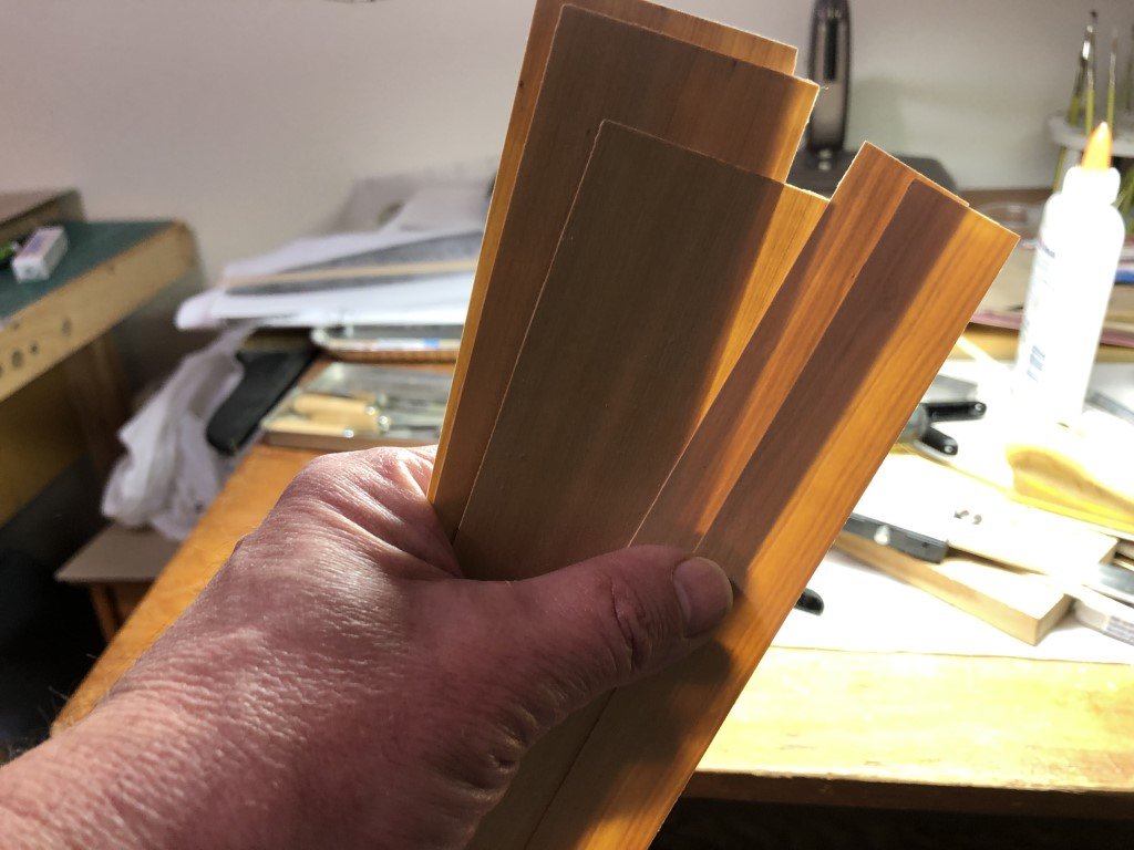
This is what some C Boxwood (I milled today) looks like in comparison with the maple. The wider slice is the same swiss pear that the waterway / covering boards were made with. I like the grain much more in the C Boxwood, than in the maple, and it is very much like that in the pear. But, I like the lightness of the maple. I don't have any holly - but is it worth another expenditure on this model?
-
Another bit of progress today. I've got a subfloor cut from 1/32" plywood and fitted for the cockpit. Once it was trimmed to match the opening, I was able to use the piece to fine-tune the depth of the cockpit - it is now a uniform 1/4" as needed. The two small holes are so I could use tweezers to move the piece in and out of the depression. It w I milled a bunch of 1mm thick maple today, as I have thought about using it for the deck planks. The wood at the bottom of the picture (above) is some of the material. I took cuts from two directions of the '1 by' piece of maple I had gotten. Some cuts from the top of the stock and some cuts from the edge: I'm not sure I like either. Material from the top has a pronounce pattern, and that from the side has a lot of 'dots'. Maybe time to get out some C boxwood instead. Thoughts?
-
To day I milled some 1mm swiss pear wood for the stern deck waterways. I decided to form them in three pieces - not as detailed as Volk, Davies; there the waterway was modeled with 7 pieces. I milled in slots for the timberheads to drop into. They are all 1/8" wide and will receive 1/8" square timbers that will be tangent to the bulwarks.
-
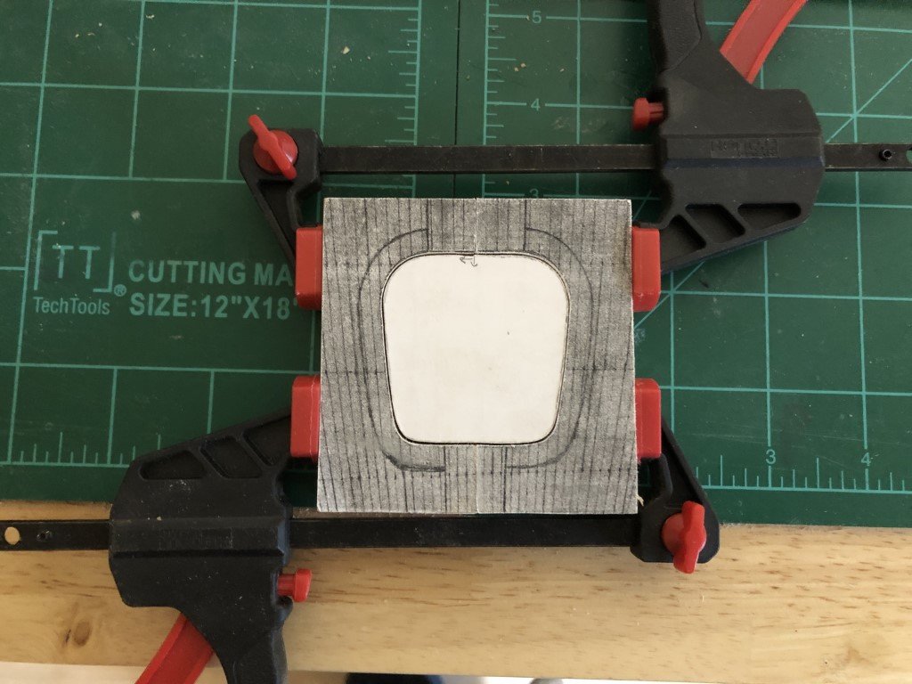
Well, so far, today has been 2 steps forward and 1 step back! I made a mold for the cockpit bulwark and currently have a layer of the to be laminate drying in the mold: Then I went about attaching the stern decking plywood subfloor. All was going well until the model slipped out of my hands and fell to the floor; I went to pick it up and promptly dropped it again. All of the bulwarks have detached. A good illustration of how weak the flush joint is. If the model had been designed with timber heads embedded prior to adding the bulwark, it is possible that everything would still be intact. This marks the first time on of my models have made it to the floor on its own - I hope it doesn't happen to often in the future! I feel fortunate that no serious damage has been done - besides detaching the bulwarks there is a small dent in the edge of the stern basswood piece. A small amount of filler will be needed, but once painted there will be nothing to notice. Now I've decided that the bulwarks will remain off until the deck has been planked. I'm even going to view this as a positive, because now it will be easier to sand / smooth the stern deck planking! Happy Thanksgiving to all that celebrate!
-
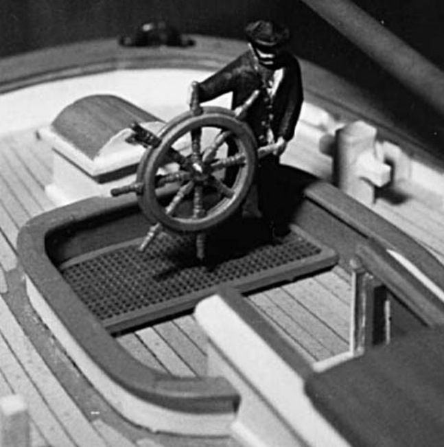
Juhu - I've learned a bit by consulting Chapelle's book 'Boatbuilding' - he writes "Cockpits in seagoing boats should be strongly built and, if self-bailing, should have scupper pipes of sufficient size to drain the cockpit quickly. The cockpit scuppers should be installed before the cockpit floor is laid. Cockpit scuppers should lead to just above the load water line. Cockpit scupper pipes are sometimes crossed, so the port scupper empties to the starboard, and vice versa; this prevents the leeside flooding." I still have not found anything about the use of gratings; however if the grating were cut into the cockpit floor planking, then there would need to be another level of planking (or such) to collect the water passing though the grating. In the Volk, Davies-Garner picture, the grating is sitting on the waterway, so water could go through the grating and then flow on the cockpit floor toward the cabin where the scuppers would be located. This does make some sense to me - it would keep the helmsman standing above the water in some cases as the water drains away - but I am not a seafaring person, so just more guesses on my end! Greg
-
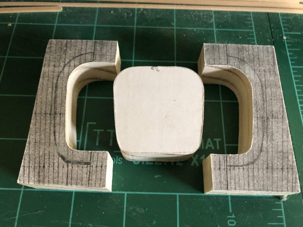
I'll keep my eyes open for additional information about the grating, in the meantime I now have created the right amount of space for the cockpit to drop under deck level. It looks like a mess, but it will provide a stable base for the ensuing work. Here's the material I plan on making the cockpit walls from: This 1/3 mm Costello Boxwood - its pretty thin; a lot of light shines through the sheets. I had made this for another modeling project (Santos Dumont #18 Hydroplane) and have a lot of extra, so I don't need to make more for this model. I'll be using 3 layers to build up the walls. The kit came with a mold for the wall to be 1/4". I will need to make a new mold so that I can form some material to a height of 1/2" to accommodate the depressed cockpit floor.
-
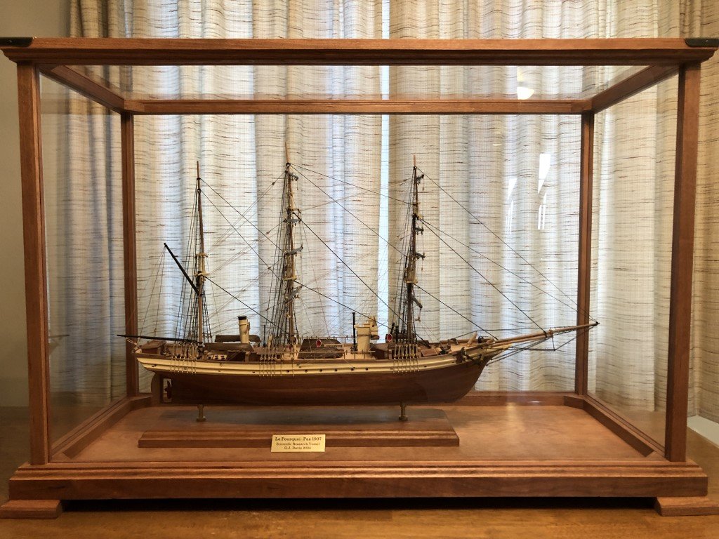
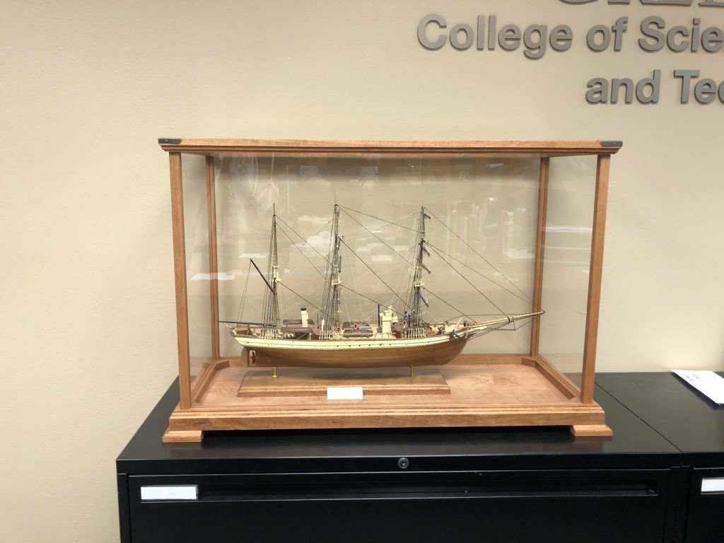
Here is the final product - case and all! After a successful trip, the model now resides in the Dean's Suite for the College of Science, Engineering, and Technology at the University of Wisconsin - Green Bay.
- 123 replies
-
- 7
-

-
- Le Pourquoi-Pas
- Constructo
- (and 1 more)
-
I had been thinking about this as well. I don't know the details of the actual construction of a cockpit in such a vessel. My guess is that the grating allowed one to stand above most of the water that made it into the cockpit area, a region that would be less slippery than the deck itself. Also, it would help keep the person from standing in water whenever there was some - so a bit dryer. But, as you note, there would need to be a way for the water to leave - otherwise, it would end up in the cabin. I have two guesses on how that may have been done - one is that there could be drainage pipes on each side of the cabin opening (due to the direction of deck slope) that led to scuppers, the other is that there could be drainage pipes to limber and then the water was pumped back out of the ship. The former seems like a better idea to me because the drainage would be passive, whereas the latter requires crew work. It would be great if someone that knew the actual answer could share!
-
Yes, I currently plan to build most of the cockpit outside of the model and then drop the structure into place. A piece of thin plywood will be made to support the planking that will be done prior to placing it in position. The cockpit bulwarks will go in next, followed by the deck level planking. I'll set some grating on top of the cockpit floor afterwards. I am very much following the work described in the Volk, Davies-Garner book. This is a picture from the book showing their version of the cockpit and grating: Victory 78's scratch build of Phantom on this forum, is closely following the book and as the hull was made, there was space made right away for the cockpit (and other below deck features). I hope Victory 78 starts posting again soon - the work is so nice!
-
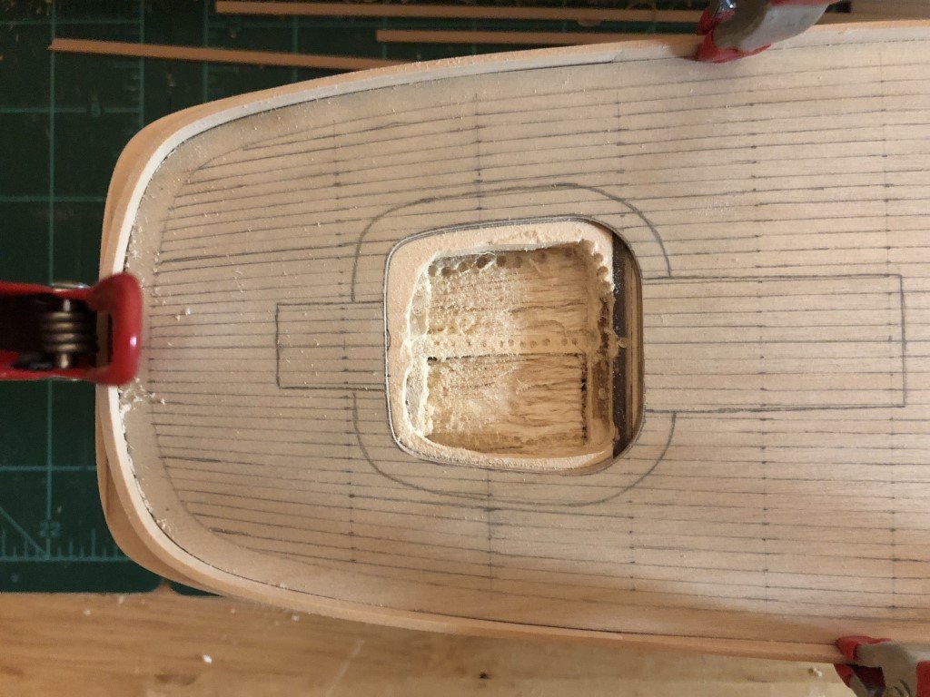
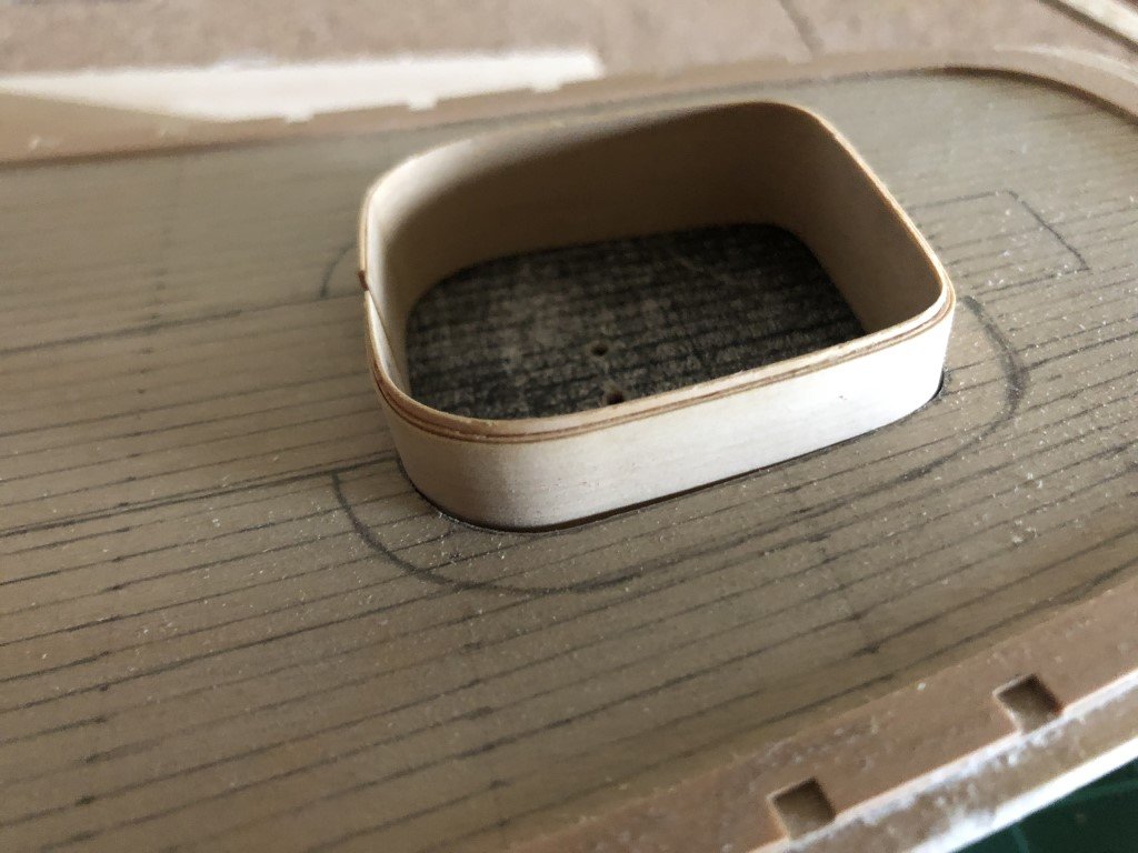
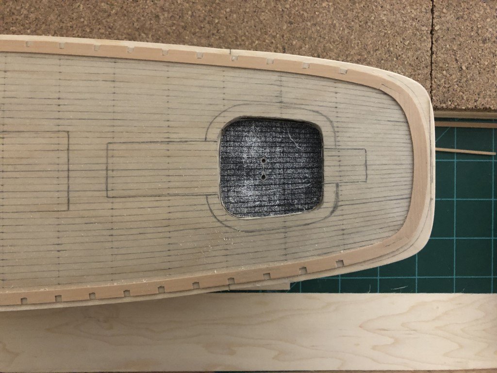
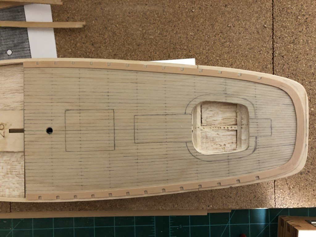
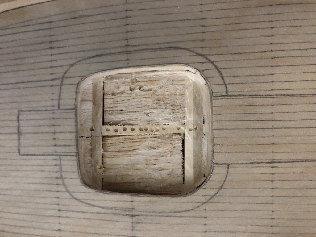
Well, I'm really going for it - cockpit surgery has begun! I'm going down 1/4" so that the cockpit floor will be the accepted 1 scale foot lower than the deck. The cockpit floor will have a good attachment - besides the center piece of wood, the front of the cockpit will sit over bulkhead 8 and the rear will sit on bulkhead #9. This should make installation reasonably straightforward. The milling is being done with the deck pattern removed - the cockpit shape has been traced on the stern deck wood and a small piece of wood that I need to attach for of bulkhead #8. I'm using a Dremel cutting bit to work toward the edges. I should have better planned ahead and did this before the hull was planked. At that time, I could have secured the hull on my mill and more easily milled out the space. To late now - still should have a good outcome!