Greg Davis
-
Posts
807 -
Joined
-
Last visited
Content Type
Profiles
Forums
Gallery
Events
Everything posted by Greg Davis
-
 Thank you for sharing your work and the complement on mine. You certainly put a lot more thought and modifications into this part of the ship's kit than I have! I will be using the kit provided barrels for the upper stern guns and the closed ports on the lower deck. In fact, I was having a mindless day when I installed the forecastle deck - now I will have a bit of a tussle getting the 4 guns under the deck nicely positioned. Good to 'meet' another Midwest modeler at approximately the same latitude! Don't be surprised if I take you up on your offer for more information / questions on this ship. Greg
 -
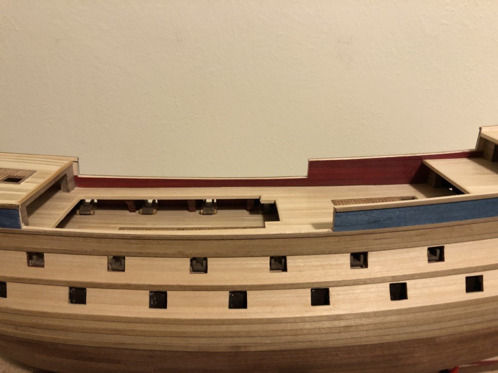
I've been able to open up the 4 round gunports under the forecastle deck. There couldn't have been much room to work / manage the guns in this area - the spacing is much closer than on the gun and lower decks. Besides these closely spaced ports, there are 4 more more that open to the front - so 8 guns in a small area!
-
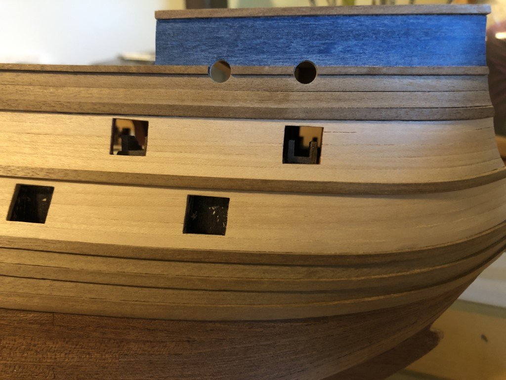
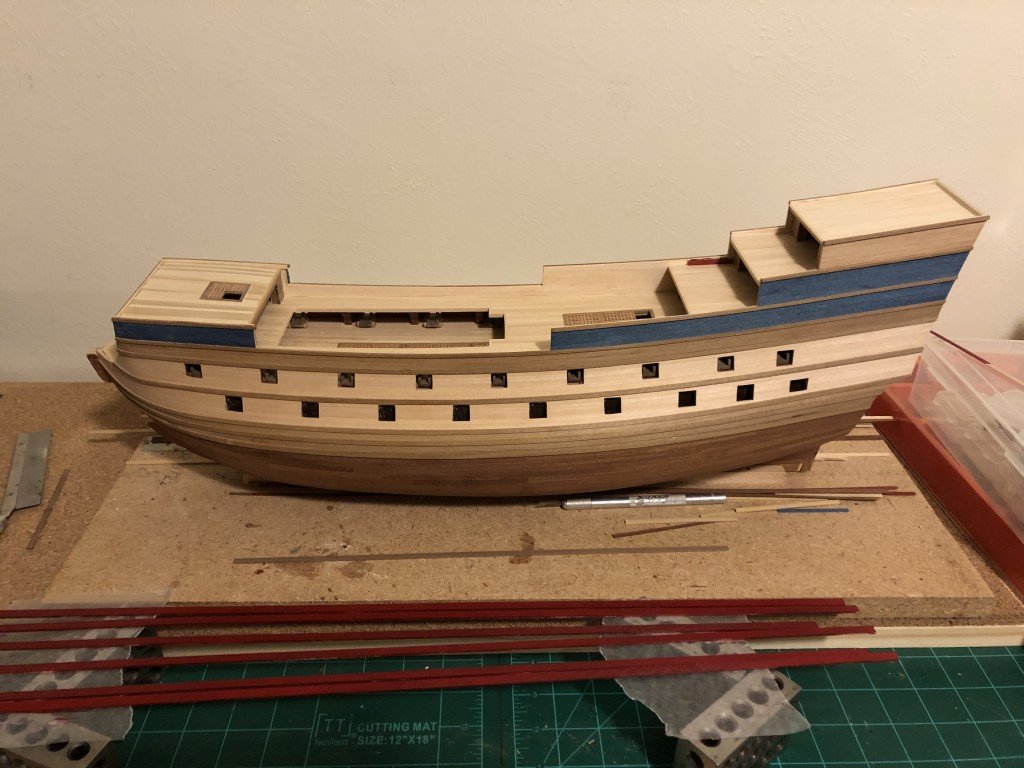
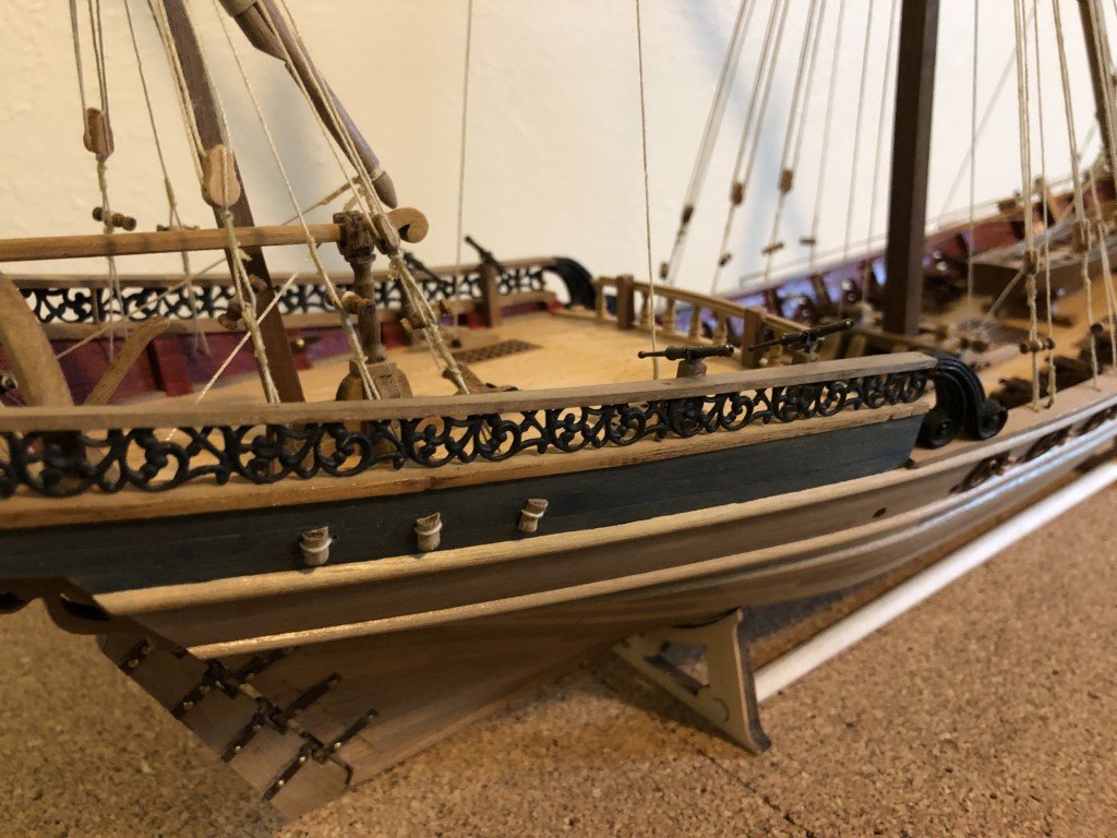
Bulwarks completed! Next couple of tasks will probably be cap rails (straightforward) and forming 10 round gunport openings (not as). The gunports are centered on the walnut strip that separates the blue planking from the brown planking. I'll probably start with a very small drill with diameter less than the walnut strip and then larger until I can start to pass a round file into the hole ... .
-
They are very confusing, many typos and material out of order. I have a multitude of notes all over my booklet! As I got closer to the end of the build, I also saw that the main drawing / plan had some serious limitations. I feel that the model / instructions should have been beta-tested by an out-of-company builder and the instructional material revised before it was released to the public. Some of the problems may arise because the instruction booklet has been translated from Portuguese to English with limited editing.
-
Yes the higher side is to the front. I remember having some confusion with the wing jig labeling and finally decided that they had been labeled for someone looking from front to rear of plane; i.e., not from the pilots perspective. It probably would have been as good, or better, if the jigs hadn't been labeled and the instructions said make a pair!
-
It's taking a bit longer than expected (but that always seems to be the case) for me to get the inner bulwark planking completed. The bulk of the planking is in; now I'm mostly left with the smaller fiddly pieces along the upper decks. Probably another 2 days and this phase will be done. I don't expect to be painting anymore, the rest of the ship will be left in the natural wood colors.
-
The last deck, the foredeck, has been added and planked. I also finished the blue second hull planking just below this deck. The red painted planks in the fore ground have been prepared for the inner bulwarks - that will go in next.
-
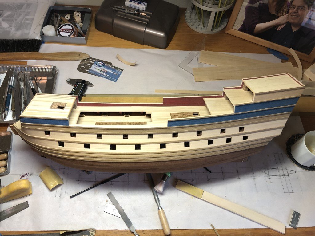
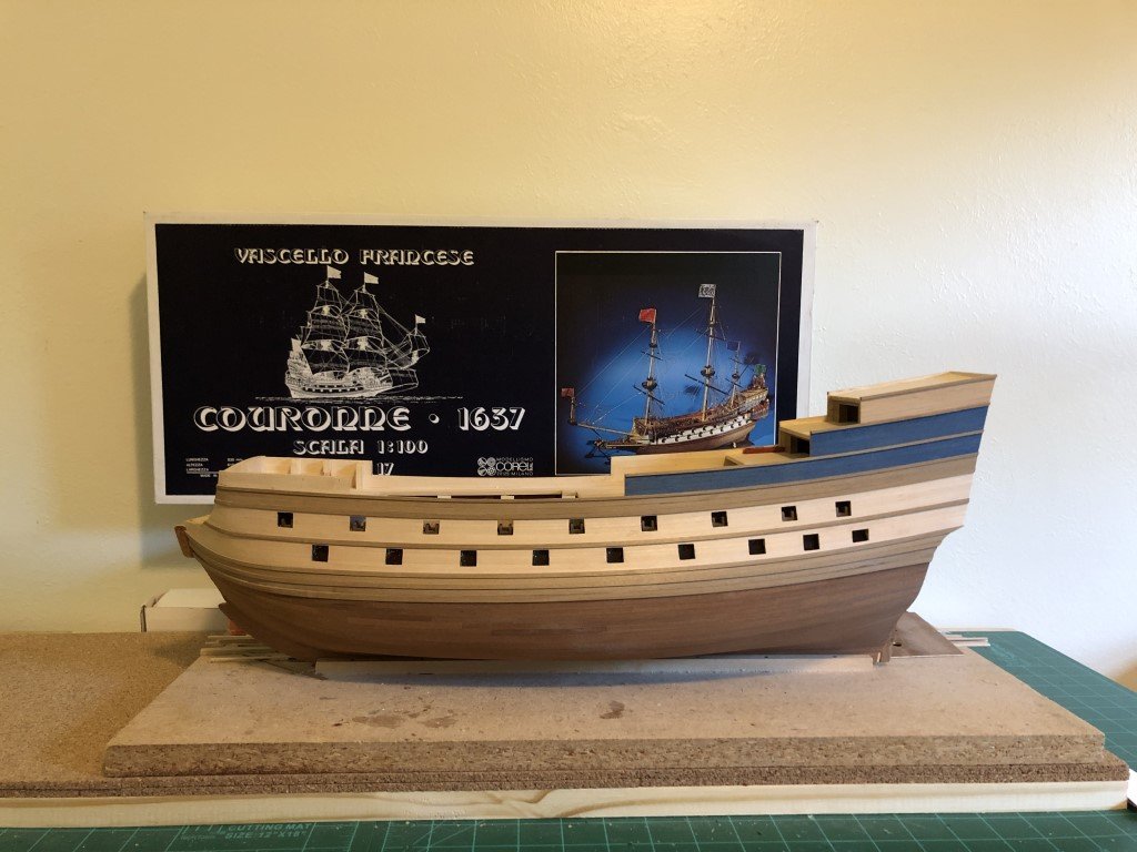
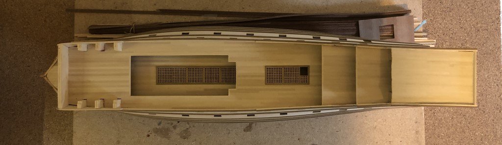
I bought the Corel La Couronne kit in 2011, during one the many Model Expo sales, thinking the sprit-sail rigging was interesting. I still feel that way and am looking forward to having the completed model on a shelf sooner than later! It took until 2020 before I began the kit and within a year was shelved in favor of a number of other ship modeling projects. As part of a reclamation of workspace, I am now going to make a concerted effort to finish the model. At this point almost all of the hull planking is complete; also, all but one of the decks have been installed and planked. This is what model looks like presently: Unfortunately, I did not take many pictures earlier in the project, but there are a few things that I do recall such as: The decks are planked with 1/8" x 1/16" basswood instead of the thinner material provided in the kit. I do recall that I used a good deal of basswood filler between the bulkheads so the first (lime) planking would create nicer contours. The second layer blue strakes were supplied already colored. Similarly, the stern is planked in pre-colored yellow planks. Going downward through all of the wales, I had planked with strakes that went from stem to stern - inspired by pictures I had seen of dockyard models of ships from this era. I then changed my tack and the lower second (mahogany) layer is made from approximately 3" long planks was applied with a three-butt shift. I recall that once the mahogany was in place, I went to my basement to sand the planking smooth and after a short time of work started to have a nosebleed. A check on the internet had me find that this was not an uncommon reaction to mahogany dust. Because it was winter when this happened, I decided to wait until the weather was warm enough to sand outdoors before continuing. It is now several years later and I am about to take it outside for a little more hull sanding and then continuing with the construction process. So, hopefully, starting this build log will keep me going more quickly (or at least steadily) to the finish! My main goal here is to get a nice looking model, one that has the rest of the work well-done, but not too dissimilar to what has already been done; i.e., an even presentation.
-
Here are the nacelles by the pontoon. Presently deciding if I should build the engine support / pylon next or if I should work on the nacelle / pontoon attachments.
- 288 replies
-
- 8
-

-
- Santos Dumont No. 18
- hydroplane
- (and 1 more)
-
Ron - I agree that the butt joints are difficult, especially because you are working with dowels. I had run a round file on the end of the dowels as they met up in the joint to provide better contact between the pieces. I also 'reinforced' the joints with an additional fillet of superglue. Even with that, they remain delicate. I think a really nice model could be had with the surfaced covered. At first I thought that silkspan may be a good covering; however, I then started to wonder if that may be to heavy for the wing structures and if a tissue covering would be a better choice. Either way, I hope that construction starts become more pleasant and that you post some pictures - especially if you give it a covering! Greg
-
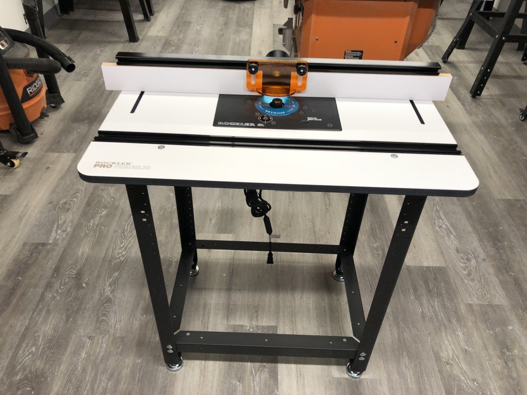
The second nacelle has been going together quite well. Waiting for tip filler blocks to dry so that I can form the two ends of the second nacelle. After that the cross-bracing will go in both. Got a new shop addition also - a larger stand alone router table. Still need to add a safety switch before using. Looking forward to using it for case fabrication among other projects!
- 288 replies
-
- 5
-
-
- Santos Dumont No. 18
- hydroplane
- (and 1 more)
-
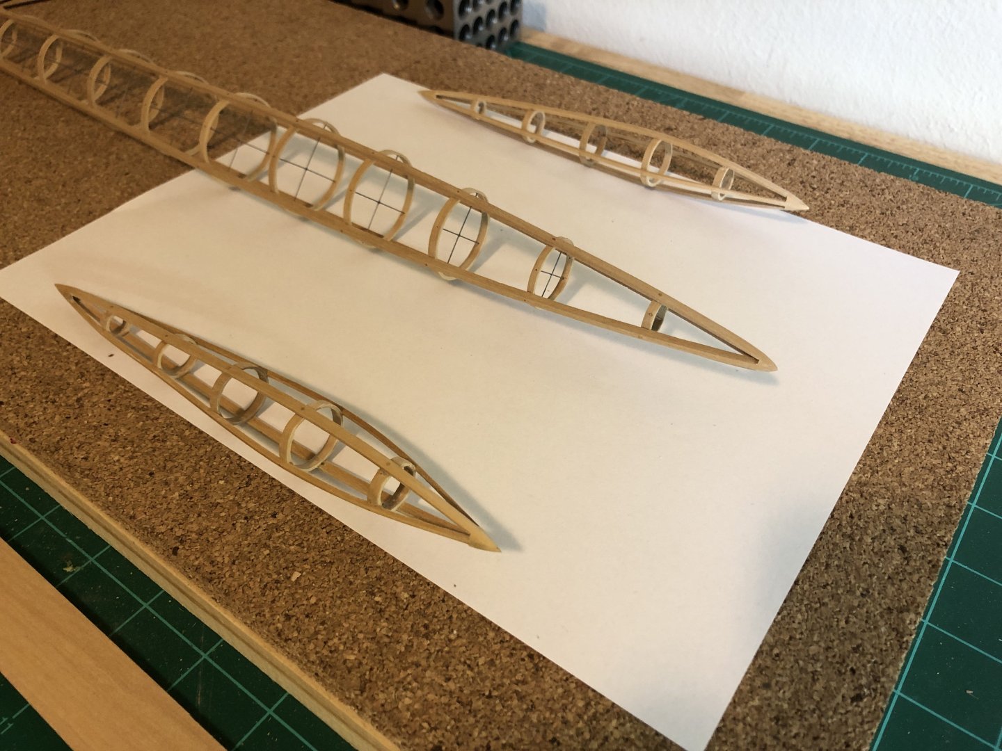
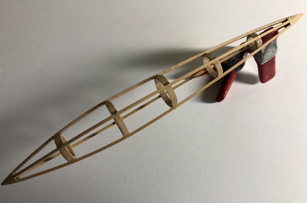
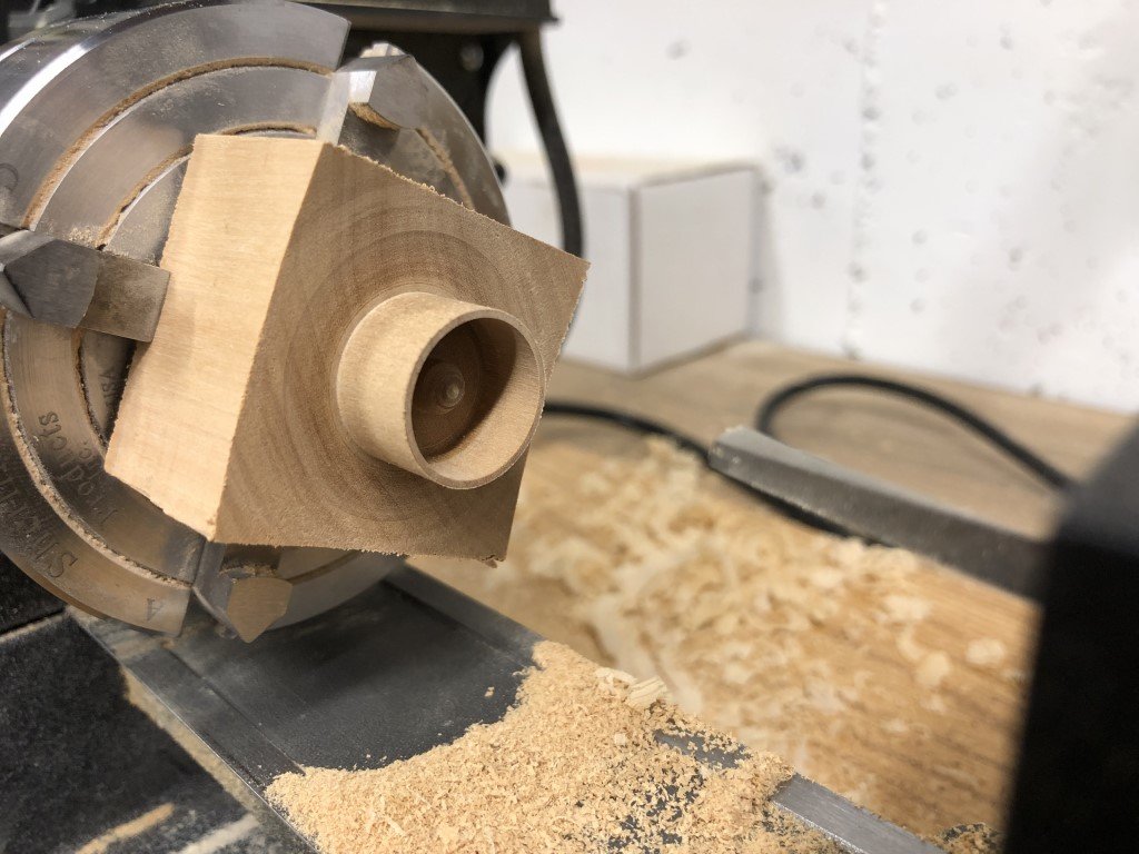
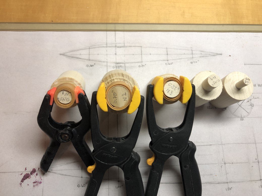
I now have one nacelle nearly done - it still needs the cross bracing wires to be added. Constructing the nacelle has been more work than expected. The main pontoon was quite a bit easier for me, probably due to the larger size of the hoops. Nevertheless, progress is being made; hopefully the second nacelle will be easier given the experience of making the first one. After I had added the hoops I didn't like the envelope of the nacelle. The middle hoop was a little too small in diameter to present a nice outline. I made a set of middle hoops, increasing the diameter by 1.5mm, and now the shape looks good to me. When making the new set of hoops today, I tried out an alternate method for making a hoop. This time, on a lathe, I turned the hoop out of a solid piece of wood. First the exterior diameter was turned and then the interior was cut out before parting off the hoops. This method doesn't take much time at all to make very well dimensioned hoops that seem quite strong. The resulting hoops don't look bad at all, but I think that the laid up ones look better due to the grain direction and are probably closer to the way Santos-Dumont had manufactured the ones for his boat.
- 288 replies
-
- 7
-
-
- Santos Dumont No. 18
- hydroplane
- (and 1 more)
-
John - I'm glad that you are interested in the project and I really appreciate your support. Noting your list of builds (and location) I have a Slo-Mo-Shun kit waiting in the wings - last year I was out to Seattle to visit my son and we went to the Hydroplane Museum in Kent to see some of the classic hydroplanes and then saw Slo-Mo-Shun IV in the museum near Lake Union in Seattle. Such a cool boat! I have obtained and read the book "Wings of Madness" as part of the background research for this project. It is certainly an entertaining book and I learned a good deal from it; however, I was really disappointed when noting that the author did not seam to understand that the No 18 Hydroplane was actually a watercraft / boat as opposed to an aircraft that could take off / land on water. Greg
- 288 replies
-
- 2
-
-
- Santos Dumont No. 18
- hydroplane
- (and 1 more)
-
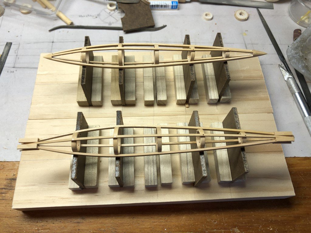
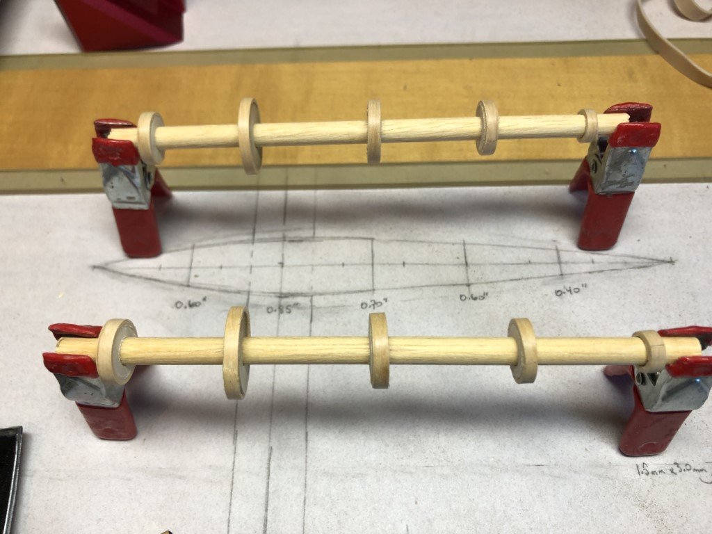
Today, I got up the nerve to part off the nacelle hoops. The work appears to have been successful and they all thread onto a 1/4" alignment dowel. Next I will set up a jig to hold the hoops in place during the stringer attachment process.
- 288 replies
-
- 10
-
-
- Santos Dumont No. 18
- hydroplane
- (and 1 more)
-
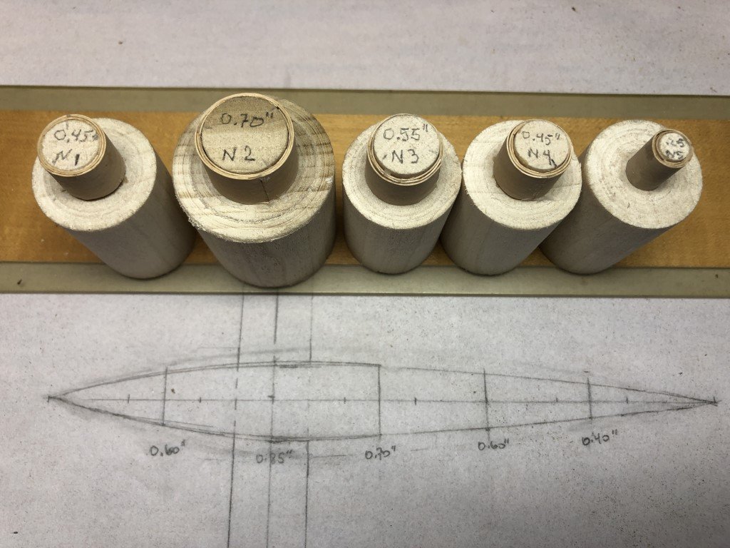
It turns out that laying up the 15mm wide strips is a bit more challenging than the narrower strips I used for the main pontoon hoops. Nevertheless, all of the nacelle hoops are laid up. The 0.25 inner diameter hoop has 4 very thin strips, whereas the other 4 have been made with 3 layers. The smallest diameter one really took some patience - there were a couple of times I thought about laying up a pair of narrower strips for this one. But all is good now and it is time to go back to the lathe to turn the hoops to the required 1mm thickness before parting off the 10 hoops I need to proceed to the next step. I also hope I remember to drill center holes to pass an alignment dowel thru the parted off pieces!
- 288 replies
-
- 8
-
-
- Santos Dumont No. 18
- hydroplane
- (and 1 more)
-
For the last couple of months I had spent a lot of time working on an Amati kit of a Xebec that I had started back in 2015 - I finished it today and got right back into this build. I've decided to work on the nacelles next. So I've just bent some wet wood around a few of the hoop formers that I had made for the nacelles. The wood strips are 15mm wide, so I hope to be able to cut off two 3mm hoops from each - one for each nacelle. This should help keep the nacelles the same size (as well as reduce the time needed to make the hoops). Two more forms to wrap up. Form #4 will not be a problem, it is the same size as #1; but #5 is going to be a challenge, this hoop will have an inner diameter of 0.25". Later, like for the main pontoon, I will build a jig for attaching stringers to the nacelle hoops.
- 288 replies
-
- 7
-
-
- Santos Dumont No. 18
- hydroplane
- (and 1 more)
-
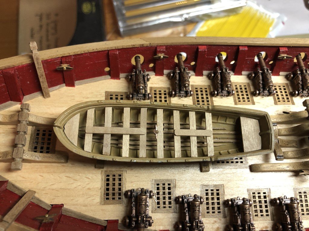
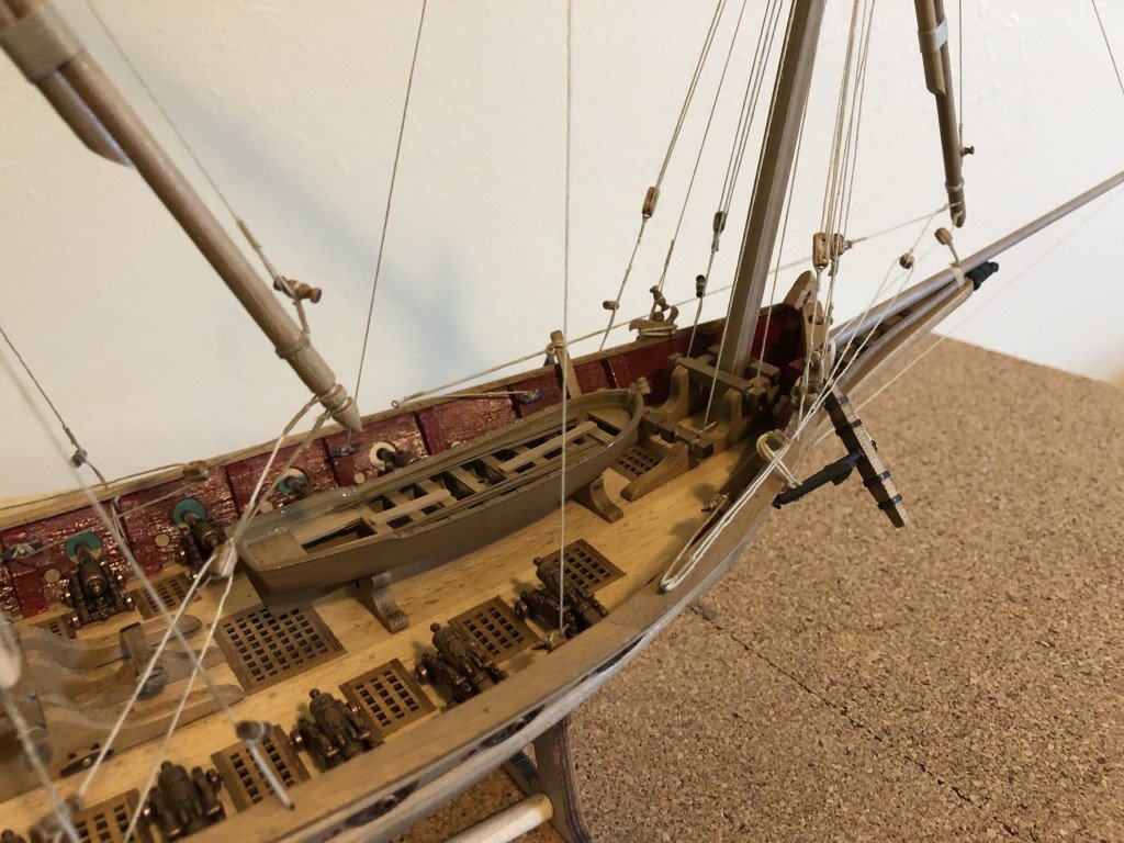
Done! Boat with oars in place, anchors stowed, and four falconets ready to fire. There are actually suppose to be six falconets, the other two go on the quarterdeck rail; however, there was a missing support bracket. So I decided to mount the four that aim outward. I've sent a parts request to Amati to see if they can send me a replacement The actual time spent on the kit was minimal considering that nine years have gone by since opening the box. Thank you to everyone that has taken a look at this build log and even more to those that have offered comments and support over the past months. Greg
-
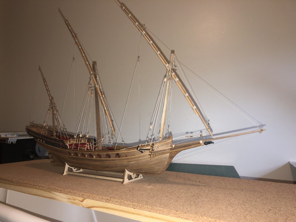
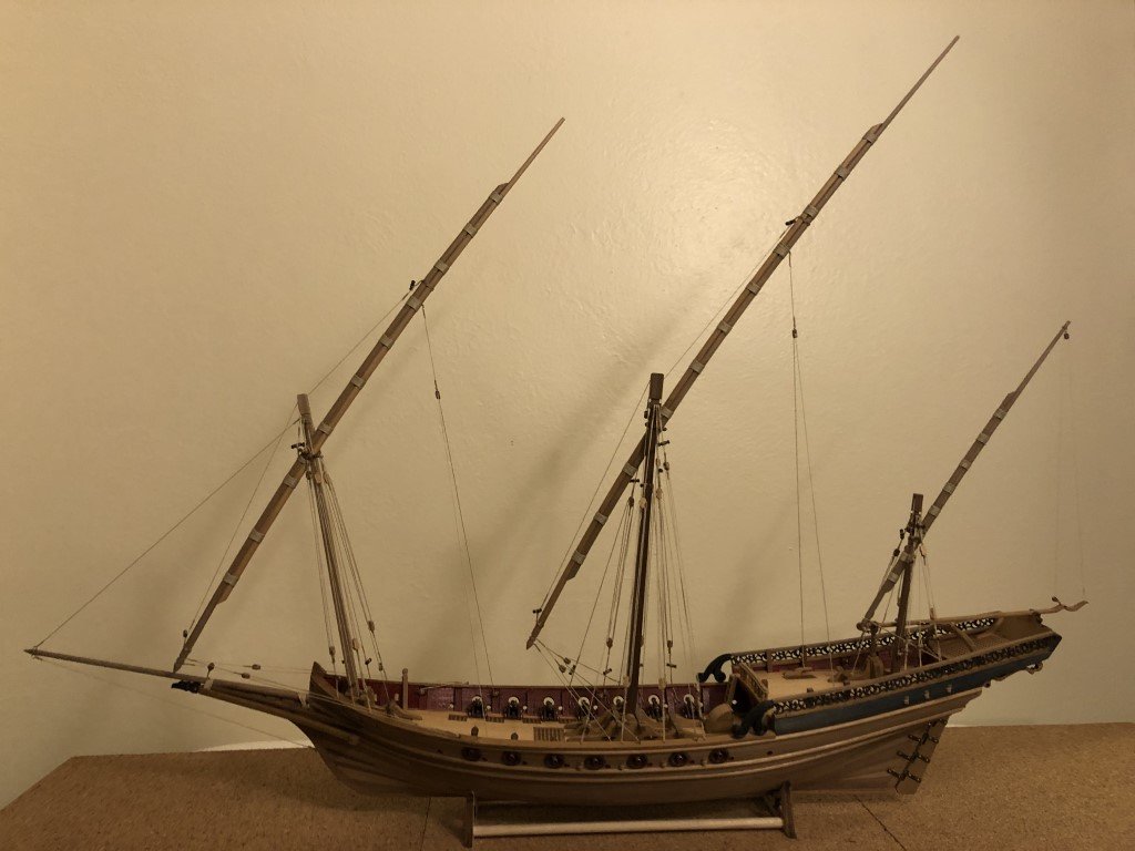
Yards are all in place and rigged! Just a few details left to attend to: mounting of the anchors, falconets, and the ship's boat.
-
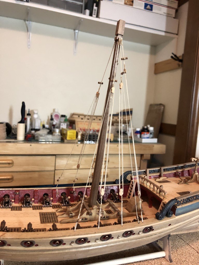
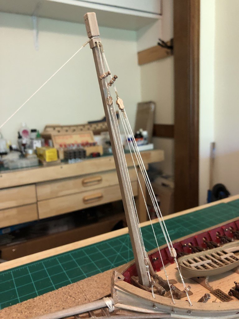
The bowsprit is totally rigged - just two lines so not a huge deal. More importantly, I've had success putting up the first set of shrouds on the foremast. It has been a learning experience! Installing and working with the toggle system feels strange after always working with deadeyes. I hope I get the hang of this soon as there are more than 50 toggles yet to install.
-
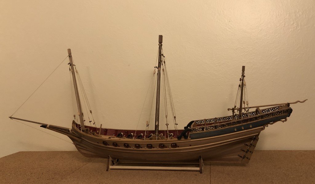
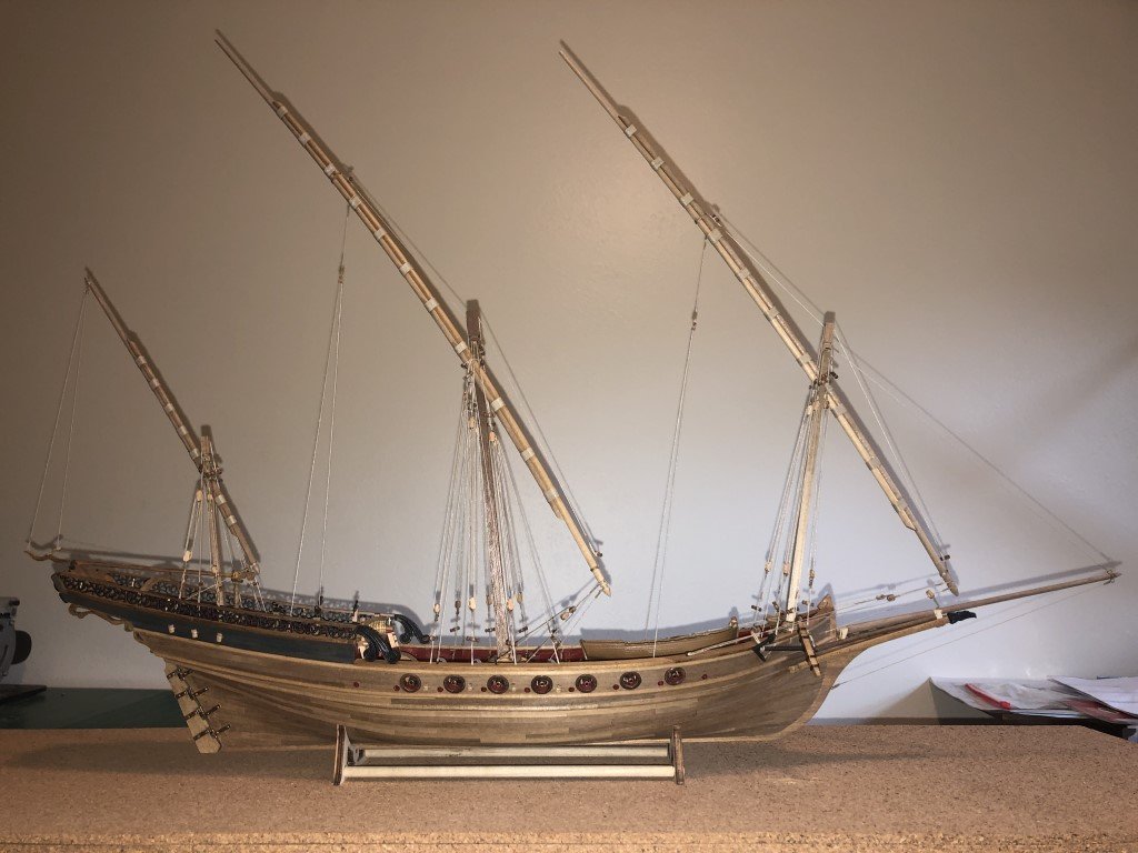
The yards are now completed, the last steps were to add the rope bindings and then to varnish them. The bowsprit is attached to the hull as are the masts. Here I have tried to get an idea of what the ship may look like when completed. It is now time to get this vessel rigged!
-
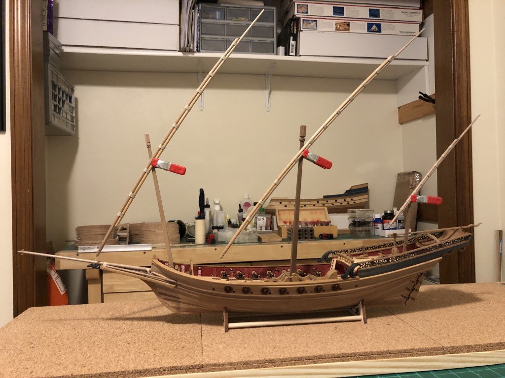
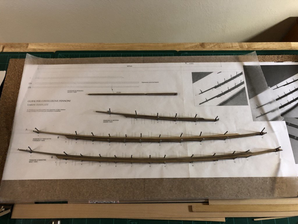
I made the pieces for the mizzen yard today, as well as the bowsprit. The six yard parts were soaked for about 45 min and have been formed into their respective curves. Currently they are drying over the provided template and being held in place by finishing nails (to big a job for pins). I expect that by tomorrow the wood will have dried and that I will be able to glue the three pairs of pieces together. Here is a picture of the yard pieces as they are this evening (as well as the bowsprit). P.S. the nails are driven into wood under the cork. This work is being done on a building board I had made for a different project where I could hold pieces by inserting pushpins into the cork.
-
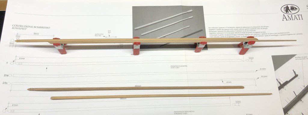
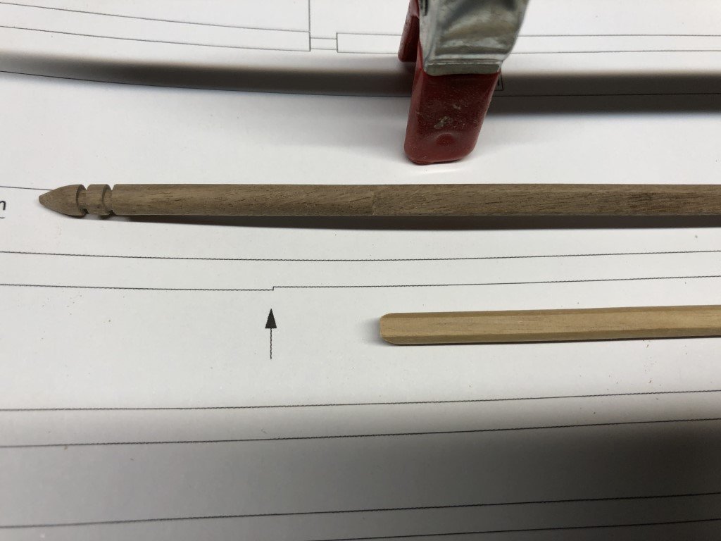
While I wait for primer on the exterior of the ship's boat to get really dry, I have started to work on the yards. At this point I have the pieces for the main and fore yards completed. Each yard is made from two 5mm dowels. The lower portion of the yard has a conical end and a pair of slots for rigging. This piece is not tapered, but does have one side flattened leaving the piece 4mm thick. I cut the flat by passing the dowel thru my Byrnes table saw. The end of the cut was then squared up with a chisel. The groves were also formed on the table saw by repeated passages and rotation of the dowel. Finally the tip was sanded to the desired conical shape. The upper part of the yard is tapered at the extreme end to 2.5mm and the rest of the piece has also been flattened to match the lower piece. The pieces will later be glued together along the flattened edges. Here the main mast components are set together along their flattened edges. They will be glued together over a curved pattern provided in the kit's set of plans. To be safe, I think it may be a good idea to soak the pieces and fasten them over the plans and let them dry to help form the shape before gluing them together - the dowels are pretty strong and I'm not sure how well they will keep their shape without a bit of coaxing. The mizzen yard will be constructed in a similar fashion using smaller diameter dowels.
-
I've spent the last couple of days working on the ship's boat. The provided hull is metal and it has been challenging (for me) to get it painted similar to the wooden parts. It has gone thru quite a few color changes to get to the point that I was willing to start adding the wooden parts. It still looks painted, but is now in a state that I am not ashamed to put it on the ship! The paints are from some of the wood effect collections that Vallejo makes. I have yet to paint the exterior of the boat. I thought it best to wait until the interior was completed as I am having to handle the boat quite a bit at this point.