
HOLIDAY DONATION DRIVE - SUPPORT MSW - DO YOUR PART TO KEEP THIS GREAT FORUM GOING! (Only 24 donations so far out of 49,000 members - C'mon guys!)
×

FreekS
-
Posts
230 -
Joined
-
Last visited
Content Type
Profiles
Forums
Gallery
Events
Everything posted by FreekS
-
Thanks for your kind words! Yes I was very pleased with the boat and it's performance. The trim was perfect and the boat as stable as a rock! Manoeuvrability also much better than expected, hull shape seems to make for a stable and fast boat. Mark, good question on control. The key is a long wavelength transmitter, so the signal will penetrate water. My very old 40 MHz transmitter can penetrate clean water to maybe 5 meters. In US I believe 75 MHz is used. Most model plane people have moved to 2.4 GHz, which is a better frequency for high dat rate transmission, but being microwave won't penetrate water at all. The antenna is inside the boat, under the wooden deck and I guess the wavelength that penetrates water does the same with water and plastic. Freek
-
Well friends, The maiden voyage of Hr ms O-1 went extremely well. The boat was pretty much perfectly trimmed in my bath and todaz was tested in the swimming pool in Zutendaal - beautifully clear water! I had a camera on a tripod under water, and one outside of the pool, and together these captured below 7 minute summary of a day worth of sailing. Yes there were some other boats, but somehow I never saw those - and they 'surprisingly did not show up in pictures'. figure that! I'm certainly happy with the boats performance, now I can get back to redoing the paint job and look for more details to include! Freek (could not find how to embed a video!)
-
I thing THE stanchoins and antennes and some maats are taken down pro to diving, at least in case of K-XVIII thats described in books written by THE XO Freek
-
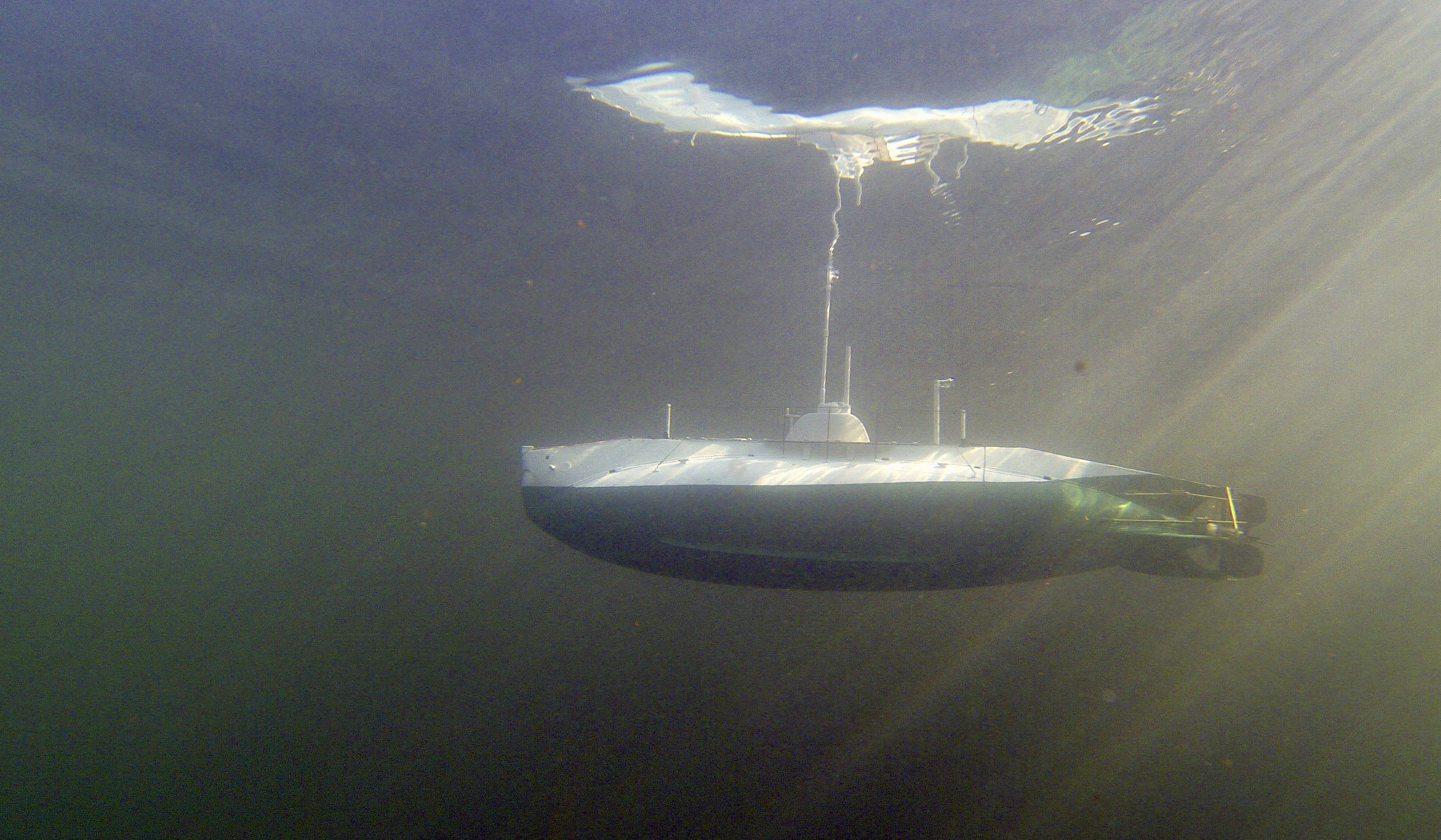
Hello all, I hereby cordially invite you the maiden voyage of hr ms O-1, to take place in a swimming pool in Zutendaal, Belgium this coming Sunday! Over the past weeks I remade the divetank , so I now have a 300ml bag rather than the 120ml before. Spent significant time with the boat in the bath to balance it, and Im fairly happy with the result. Under water the boat seems to be level with the tank pumped full, and above the water, while it does not quite reach the painted waterline, the decks are nicely above the water. Subs always have 'variable' water lines anyway. The pressure sensor inside the boat switches the pump off when the bag is full, and then the boat just dives. Trimming it with the pump leads to below nice image of a sub 'hanging on the periscope', that's what we aim for! Freek
-
Given the wealth of targets on this forum, I loaded some more shot - now nearly 2 kg on board and total weight of the boat is 3.8 kg; exactly the nominal weight of the RL-boat divided by 32 to the power 3. Seems the hull shape is pretty good to drawing. By the way - I was given the drawing set of this 1905 boat by Fred Huygen, who unfortunately passed away a couple of weeks ago. He built many per-war Model Dutch submarines including Cornelis Drebbel , a beautifull oar powered sub from the 1760s and O-13 - still on patrol, for which he built the model for a TV documentary about her disappearance off the Danish coast in 1941. Both my subs were inspired by Fred's work. Yesterday was a large submarine meeting in Cologne, and we missed him. Back to the present. The pic below shows the wet testing of the boat to determine the volume of the dive-bag. The stern is lying in a container of water, and using the transmitter and some kitchen scales. I could determine the dive tank is only 120 ml. That's much less than the 300-400 I need to get the boat anywhere near the waterline when not submerged. I thus ordered some more of the tough plastic sheeting to try make a bigger one. The shot is pretty much distributed to have the boat level under water (keeping a reserve bag of 250 gram shot in place of the dive tank - which I can reduce if I manage to make a bigger one. As seen in my bath, the boat lies a bit deep and not perfectly level. It's pretty stable though. I took both my boats to the world famous submarine day in Cologne, unfortunately my K-XVIII refused to dive after a nice round on the surface - pump seems to have failed or developed a control glitch. And with so many large (5 foot or more), and FAST subs in the water I was not comfortable trying my small boat with its minute reserve buoyancy. Rather do some more bath work! However here were some of the visitors.
-
With 1.3 kg lead shot glued in the hull, so that the tech rack slides just overtop. With the lead the boat now weighs 3.2 kg (sorry, i don't calculate in pounds!), and based on the displacement I expect the total weight to become 3.8 kg, including 200 gram or so of water in the dive tank/bag. The boat has not been wet (as the paint is still wet) but next step is to carefully balance the boat with the remaining lead shot in a tank, and of course check for leaks. Exiting!
-
Starting mounting the deck covers, and the first set of planks on the deck. The rope is about 0.4 mm, so maybe. 1 cm in RL. the rope is tightened by a 12 mm long tightener, I bought 6 but looking at this picture I think it's a little too big for this scale. I may look for another solution for this. Any ideas how to keep this tight Unobtrusively? The hinges for the deck covers are still missing All for now Freek
-
Hey Piet, those are MUCH nicer torpedo tubes than the two black ones I built for my KXVIII, at the same scale. Really I'm very impressed! can I order a pair, working and able to fire my rubber band Torpedo's? Just kidding !! Yours is the best combination of a superb build, great link to history and personal story - I read it every day! Freek
-
Thanks Piet, My farther was born in Indonesia (well Batavia in Nederlands Indie at that time), so he was one of the Dutch that your father defended! And my wifes mother comes from Surabaya! Its nice to see y'all ( now where did I pick up that term) being even more impatient to getting O-1 wet that I am! But as Piet points out, these old submarines had many details on deck and since I will have to trim her with lead shot to within a gram or so I want nearly everything mounted before I do so. Now working on the deck, where two of my pictures show a nice wooden planked deck, similar to what K-XVIII had. making that is simple and fun work and then comes the hinges to the doors in the deck to load Torpedo's and such. They won't be functional and that's good as my metal working skills are nearly non-existent! Cheers Freek
-
Well, Ian, thanks for your interest in the maiden voyage of hr ms O-1. I am going much faster than my first sub (since i actually follow à fairly conventional build strategy instead of the hair-brained "bread and butter" strategy I used onnhr ms K-XVIII). There are several interesting dates in the diary, including August 16 in cologne with a very distinguished U-boot building club. Also a pool run in Belgium in September. But first I plan I have to finish most of the additions so I can then start to glue 2 kg worth of lead shot inside the hull and balance her fore and aft to a gram or so, in a plexiglass "fishtank" I have. Trimming will be a challenge as I have a "dry hull", and so while I can move weights, I cannot also reposition floating foam pieces in flooded areas of the sub. But then the pictures I have of her sometimes say "O-1 with crew and torpedos moved to the back so the mouth of the torpedo tube can be seen. It's not like this boat had a firm waterline. Thanks for all your interest - I will be sure to post pics and videos of a maiden when it happens! Freek
-
Dear friends, Started painting the boat, in colors close to the model in the Dutch Navy museum in Den Helder (and that I just happened to still have from K-XVIII!). Using normal brush - airbrush did not existing 1905!. "Tjetten" it was called. In spite of professional blue masking tape the waterline needs some correction. Freek
-
Piet, Thanks! I do believe though that the K-XIV to K-XVIII class also did not have bilge keels. Not on my model at least! Freek
-
Dear all, Lots more details made such as the stabilisers (Piet you can translate "kimkielen"!), and the stanchions on the deck, held in particular tiny holders. The stabilisers fins are again mounted with carton flanges impregnated with epoxy resin. Next step is painting of the hull followed by the deck planking. All for now again! Thanks for your interest! Freek
-
@Piet, bedankt voor het compliment! As with most ships, fotos indicate many changes made during the boats life. As this was the first Dutch sub, it was a testbed. In fact the drawings I have are of the "mid-life conversion" when the dangerous petrol engine was replaced by a Diesel. The early photos often show two short masts with stripes fore an aft, I think to help trim the boat. Later fotos seem to have three full masts with navigation lights etc. As my O-1 will be a working model, and those masts were clearly taken down for submerging, I will make the early version with the two "trim masts". As I call them. Another very visible feature of the boat are the flanges that were used to rivet the deck section and the fins to the pressure hull. Rivets themselves are only visible in dock fotos, I think they were probably hammered flat and covered with many layers of paint. I cut the flanges from 0.4 mm carton (so in rl they resemble 12 mm steel), and glued them on the boat. Next they were coated in thin 2 component epoxy resin to make the waterproof.
-
Subsail is over again. The technical bits of hr ms O-1 were finished on time and seem to work. However, the boat has not seen water yet as its unpainted. My other boat (K-XVIII) did get into water and even fired a torpedo but I had little chance to film in the pea-soup like water. On a short holiday in Switserland I took a box of tools, including my 15 W soldering iron. So after mountain hikes I could make some of the details. First the steering wheel, in the case of O-1 mounted outside the conning tower and horizontal. The coin for scale may be unknown to some, as the Dutch have discontinued it but the Germans have not. Here is the completed steering wheel, and the mast. This submarine from 1905 still had three masts (plus two periscopes). Also these old boats had lots of details, here a few thingies for tying ropes to, foundations for the fore and aft-masts, and guide-eyes for the (anchor?) chain (I have not found out yet if the O-1 had an anchor)! Greetings Freek
- 104 replies
-
- 10
-

-
Ok took me à while, but thats the torpedo propellor, not the ships propellor !! LOL Freek
-
Piet, can you explain the 31 mm remark? I thought 21 feet in length is about 7.2 meters in "real" measures, and sound make some 14 cm on your 1:50 scale. Also I think you should look for the V53 (53 in superscript) torpedo, that was the Dutch torpedo used by O-19 until they ran out and started using the Mark 8 I believe. It is however also 7.2 meters long. I'm pretty sure that the deck tubes were that long, and took these 21 inch Torpedo's or older 18 inch ones with an insert Freek
-
Thanks Piet! May has a number of long weekends! Last week I finished the insides of the O-1. Below picture shows how the servos have been put in place and these operate the planes. Behind them a waterproof bag is placed as a dive tank. It van be filled with about 200 ml water and should then submerge the boat. In the front compartment are the electronics controlling the pump, an automatic leveller so under water the boat will come to an even keel, and two LIPO accus underneath the electronics. The main functions have been tested dry, and tomorrow the O-1 will accompany the K-XVIII to a annual submarine model event in the netherlands (Seabottom Subsail). There I can get further advise of the experts and spend a nice day sailing K-XVIII. weather forecast is great! I'm switching again to outside work, planning to make the distinctive "eye" for the achor or mooring chain (not sure if she had an anchor!) out of messing, and also still need to make a square of messing rods connecting the fins holding the dive planes and rudder. Oh and here is another model in a Dutch museum!
-
Some further work on the stern. Last time I had built in the drive motor and tested it. Now I mounted the pump which will fill and empty the dive tank on the next bulkhead. On the photo you can see the tube drawing water from "the sea", and the black pump head of a 200ml per minute peristaltic pump. The pump motor is visible on the near side of the bulkhead, which can close off the stern section with one screw attached to that is a half-cut plastic tube which will hold all further technicals. In the next picture the assembly is closed and the pushrods for the planes can be seen. the servomotors to the side have been discarded as I want to have miniseries mounted on the pump motor to save space. And that is the next job! Freek
-
Dear friends, Last week I drove to Nürnberg in Germany with my K-XVIII submarine to sail her in a nice outdoor pool with a lot of other subs. I managed to get in over 2 hours of sailing before the batteries were exhausted. Fired three of my rubber motor Torpedo's and generally had lots of fun. Enjoy!
-
Here is the first test of the motor. I'm running it of a 12 Volt battery and measuring the current drawn. After increasing the power, the prop is making the bath into a whirlpool! I'm going to have to use lower voltage or program the controller to work better at low power settings. Good news is that even with .3 to .6 amps it's already running nicely, and the drivetrain seems well lined up. Freek
-
For gunner on seat see here http://www.dutchsubmarines.com/pictures/pictures_kxv_wwii.htm I think the seat could swing closer in than where Piet has it now. I have seen some pictures of a kind of cover structure covering the rear part of the gun when submerged. Not sure if it was actually used. Freek
-
With the rudders and dive planes finally mounted, I've turned to the inside of the boat. Here is an inside shot of the stern Parton the hull. The pushrods for the planes and dive planes end here inside a nut assembly that will contain an o-ring, sealing the 2mm think pushrods from the sea (well, pool more likely!). In the centre in the stern is a spring loaded shaft seal mounted in a wooden holder, the wood is thoroughly impregnated with epoxy. Behind the shaft seal is a short shaft running on three bearings, of which one is in the conus behind the prop. Next, I mounted the drivetrain. The small brushless motor is optimised for relatively low rpms (8000 or so) which should drive my low pitch but large propellor with not too much tongue (or current). I made a wooden motor mount which will be glued on one of the bulkheads. Behind the motormouth is just enough room for the stiff connection between the motor axle and the shaft. The motor is screwed on the motormount, and if I unlock the prop from the shaft, then the axle and motor can all be pulled out of the boat for maintenance. Next is to design how the servomotors will operate the pushrods; as you can see from prior photos, if bothe rudder and dive planes are swung out fully, they will hit each other, but when the dive planes are neutral, the rudder could swing out fully. As my boat is small and will be used mainly in swimming pools, I will want to get a small turning circle. So I have to do some thinking on how to regulate the operations of planes and dive planes so they do not interfere but give maximum manoeuvrability. Ideas welcome of course! Cheers Freek
-
Great looking gun Piet! Are you going make the seat for the gunner also? Freek