

FreekS
-
Posts
180 -
Joined
-
Last visited
Content Type
Profiles
Forums
Gallery
Events
Posts posted by FreekS
-
-
Hi all, the build continues - slowly, as usual!
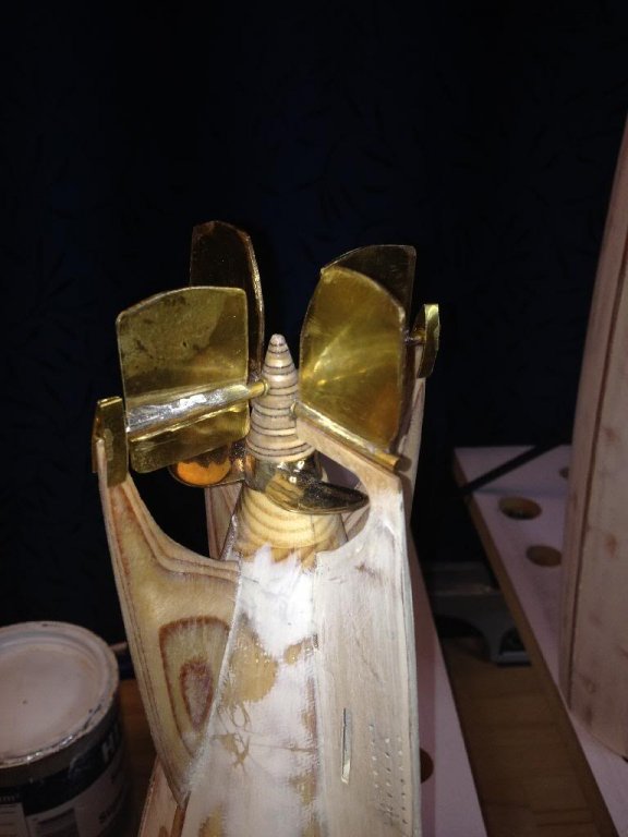
This week I have been working in the dive planes and rudder, both made from 1 mm messing, soldered to the shafts.
I am not a star in soldering , but by cooling planes already mounted I got a strong bond. Only the little "balance planes" on the opposite side of the shaft proved impossible to solder without destroying the other connection, so I mounted those with 2 component epoxy. Seems strong enough.
I filed off excess solder - the whole thing looks like it will work though it's probably not the very best looking part of the boat. Still have to polish and paint the planes though. The conus already contains one of the bearings for the shaft, and so it will be fixed by the propshaft, the planes shafts and the two wooden fins. The holes in the hull for the pushrods have been drilled, so next will be building and mounting the propshaft and motor connection, and the linkages to the pushrods controlling the planes.
- Elmer Cornish, GrandpaPhil, mtaylor and 4 others
-
 7
7
-
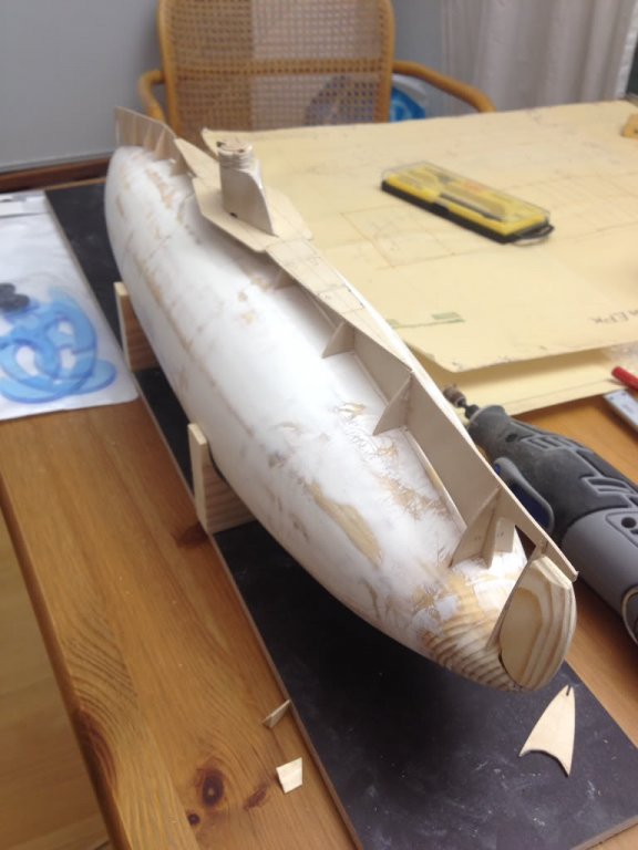
Hello all,
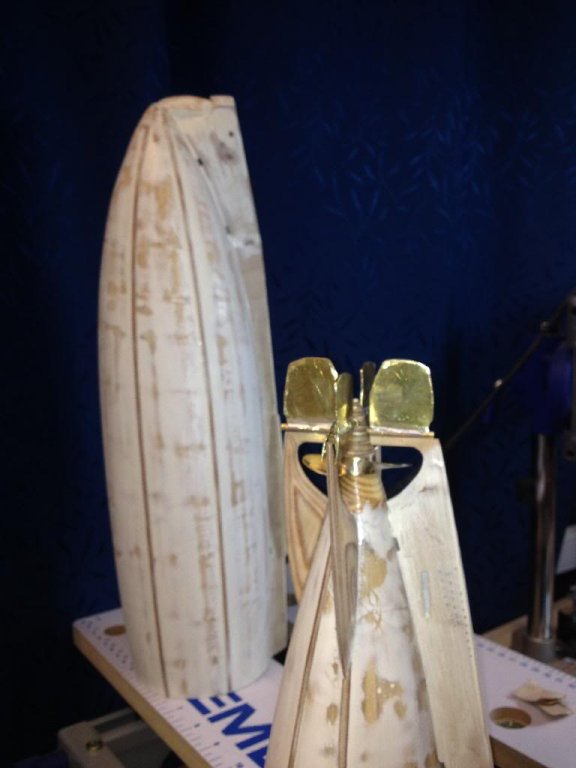
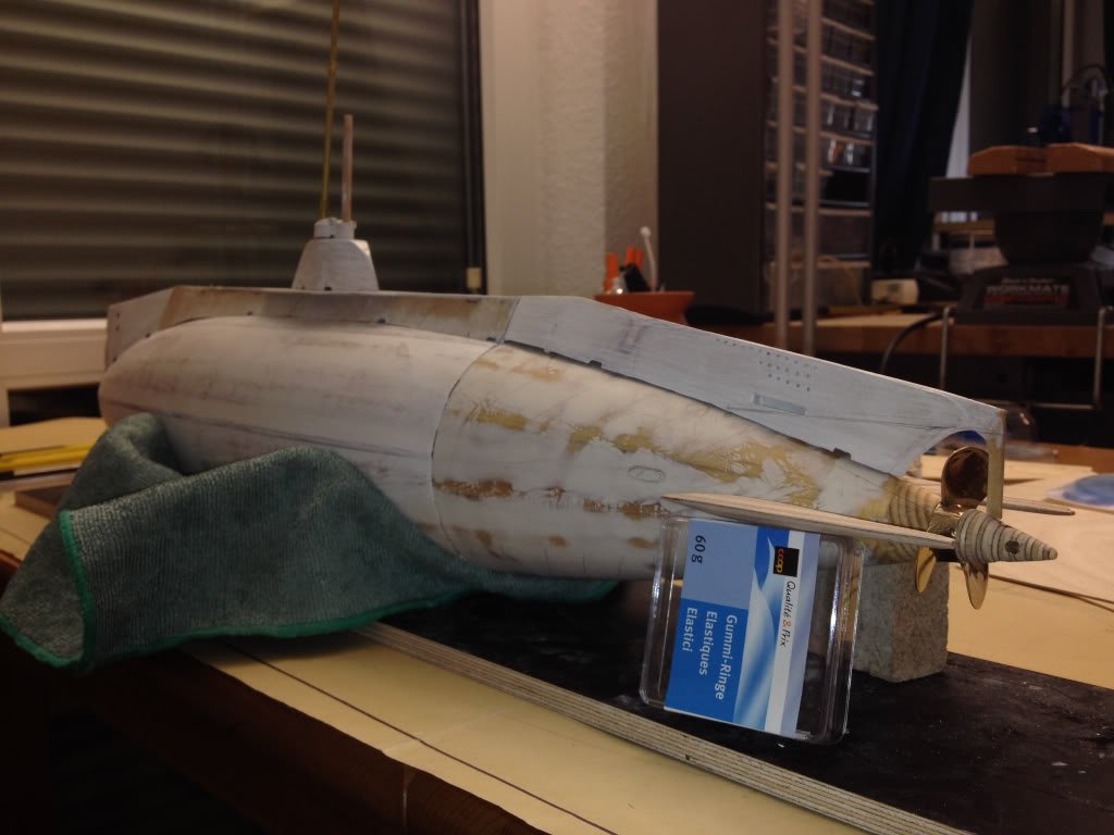
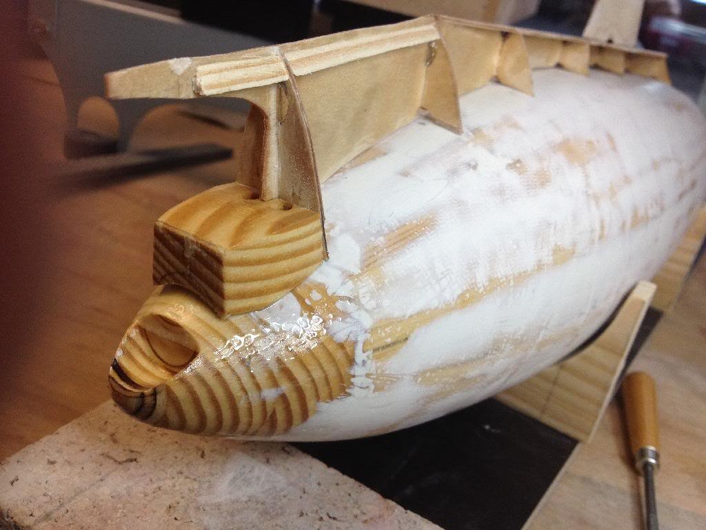
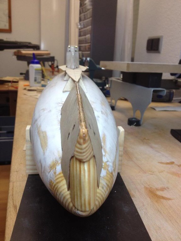
Moving aft with the build-I've been working on the fins that support the rudders and dive planes and the aft conus.
On attached photo the shafts for the rudders and diverudders can be seen, provisionally mounted in their final position.
The prop will have a bronze water-lubricated bearing inside the aft conus, which is further supported by the two shafts (rotating) and thin wood pieces of the vertical fins. Hope it will all be robust wrt the forces that may act on the planes in a turn or dive!
The bearings are part of a large number of inside components that are underway from various Internet shops. Luckily I only manage to build a sub every 4 years or so, as the total cost of components is getting to be impressive. The main motor and propshaft have arrived - but I need the bearings to continue !
Freek
- Elmer Cornish, garyshipwright, Piet and 6 others
-
9
-
It looks like a simple model, that O-16 . but I'm sure that's deceptive! Every time I look in the box of the Admiralen klasse destroyer I think "wow that look like lots of small and complex parts" and then I reckon it's easier to build a working sub like the O-1! But I'm sure I will get to building those beautifull dutch models !
Freek
-
-
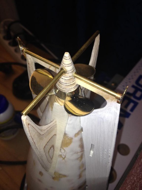
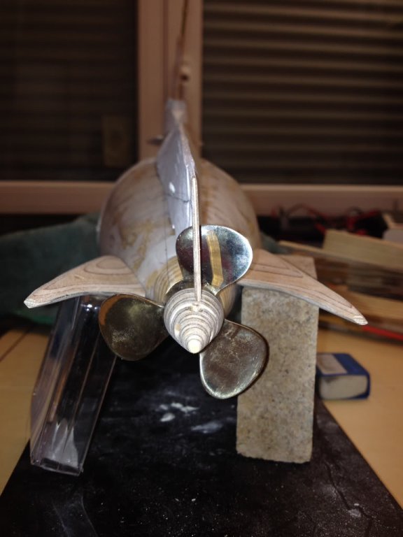
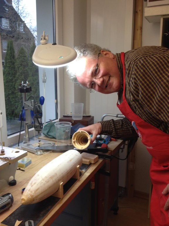
Today was another milestone. The prop I ordered from the props hop arrived! It looks fabulous!
The prop has a diameter of 52 mm, has a small pitch (so a relatively small size motor can be fitted), and a 4 mm smooth hole for the shaft with a small locking nut. This is needed as with a threaded shaft it would become very hard to remove the prop once mounted. Now I plan to make sure the motor can be unscrewed and then the shaft pulled 'into' the boat.
The prop will look like an integral part of the hull, as a small conical part of the hull continues behind the prop.
The conical stern piece has two boreholes through which the "shafts" (probably not the right word) of the rudder and the dive planes will turn. Those will also turn on the horizontal and vertical fins of which two are shown in below pic.
Lots of decisions to be made next.
Do I let the propshaft continue into the conical stern piece and place a bearing there, or do I leave the stern piece "free hanging" and have both bearings inside the hull?
How to rigidly fix the conical stern piece which will be fixed on top and bottom to the vertical fins, but not to the horizontal fins as that connection necessarily is a turning shaft for the dive planes.
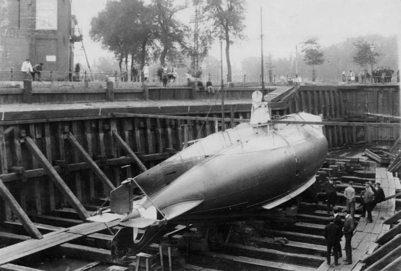
I think I put a pic of the stern of the real boat in an earlier post - it will be a complex build!
Freek
- Piet, hexnut, Elmer Cornish and 5 others
-
8
-
In some of the books about Dutch submarines I think I read that the deck was regularly scoured with sand, resulting in a white look. This would have been common practice before the war when the boats were receiving visitors in harbour. When I made my deck planking on the K-XVIII the objective was to be fully wat proof so I choose 0.8mm by 1 mm waterproof birch triplex and added some clear, matt varnish.
Freek
- Piet and PacificCrossRoads
-
2
-
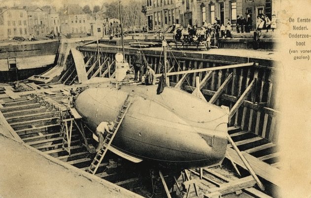
Flip
Thanks for the idea! I've found a number of photos of the dock, and maybe once my boat is ready I will actually build the dock as a stand. Probably Parton the dock as it was much bigger than O-1
Thanks for you interest!
Freek
-
hi all,
On photos of the O-1 clear horizontal seams are visible on the hull. I presume this is where steel hull plates are riveted ov each other for strength.
On another forum I saw a means I'm making this,
I glued thin, 0.8mm think wood strips to the hull, and applied epoxy putty to one side of that, while leaving a step on the other.
Then with a sanding machine I sanded the wood and dried putty even to about a 0.5 mm thin step (equivalent with 16mm steel plate in reality.
I have a number more to do but it's pretty simple to do. I am very curious what it will look like after painting (and possibly applying rivets)
Freek
- GrandpaPhil, Piet, mtaylor and 2 others
-
5
-
-
More work done on the superstructure. Did some finishing work on the bow plates using epoxy resin. Needs a few more rounds I'm sure! Also built the rest of the side plates of the superstructure so that the shape of the boat is getting close
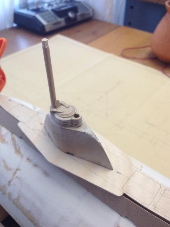
Also did some work on the hatch, periscope and the little hatch that closes the periscope hole when retracted.
Freek
- Piet, Elmer Cornish, GrandpaPhil and 3 others
-
6
-
I have now completed the installation of the bayonet. It is glued in with epoxy glue and (hopefully) made waterproof with epoxy resin.
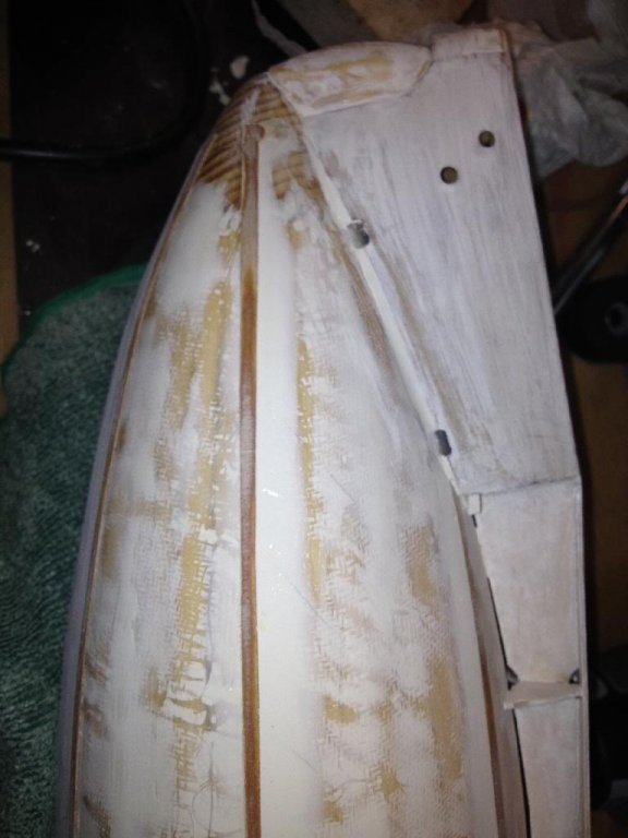
Next is to start to work on the outer plates of the deck section. These are difficult, I am using 0.8 mm triplex wood, which bends mainly in one direction. Especially at the bow it needs to bend in two directions. So I have installed some wood blocks as glue surfaces.
The two front hull plates have been glued in (compare with original foto on page 2).
The torpedo tube door will not be functional and has been glued in place.
All surfaces under the plates have been treated with epoxy for water repellency. Clearly there is some work to be done with plamuur/putty as there are a few unwanted curves in the wood. But that will be fixable I think.
Freek
- Elmer Cornish, Piet, WackoWolf and 5 others
-
8
-
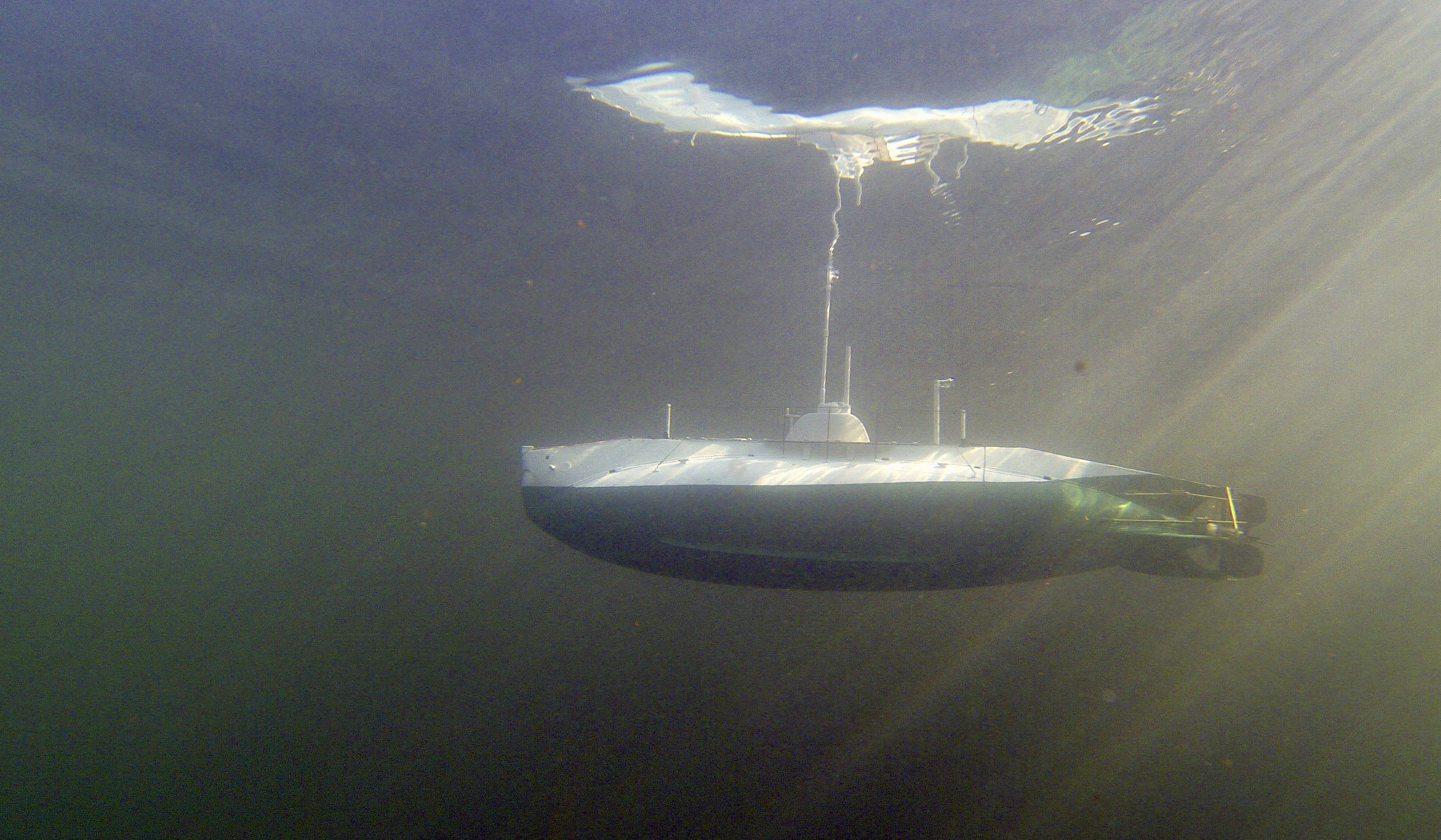
I remember this, took me two months to create the deck planking! Like you I cut and sanded individual planks to about 1 mm width and glued them on the dark grey painted deck. Then I varnished them. Boat has now had 19 patrols (and an equal number of dives and surfaces!
 ) and the deck looks a little weathered. Practice in the navy was for the sailors to have to sand these (with sand) regularly until they were truly white. I'm sure that went out with the first war patrols! freek
- Piet and PacificCrossRoads
-
2
-
I know it's old fashioned, but in some countries there are still model shops you can go to, get advise and pick up a good set. What set depends largely on what country you are in and what frequency is legal. I'd go for 2.4 GHz
Freek
-
The glue is not the only thing that's important. The hull, when wood, needs to be sealed as otherwise a scratch in the paint can lead to swelling of the hull. Epoxy or polyurethane resins are commonly used for that. Both will need final coatings to prevent discolouration due to UV light.
Freek
-
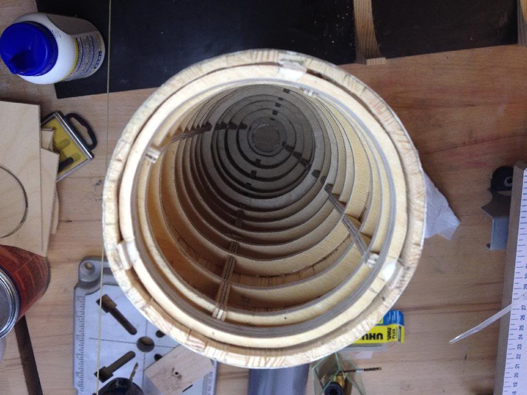
After cutting the sub near the stern, I will now mount a bayonet so that the boat can be opened and a "tech rack" mounted in the stern section which can be pulled out of the bow section.
As the bayonet is slightly smaller than the boat, I glued some wooden rings into the stern section. As this section gets narrower to the stern these rings can be firmly mounted. The bayonet fits well in this (but is not glued yet).
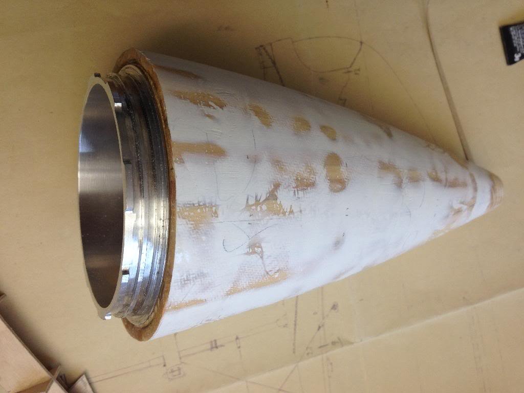
The bow section gets slightly wider towards the bow, and thus the wooden rings have been fixed with three small wedges. These allow the ring to be precisely centred and allow the bayonet to be test fitted and the two halves of the boat connected. The wedges have now been glued in place and the next step is to fix the wooden ring with epoxy resin.
This was definitely a slightly scary operation - but it looks good - though only when the seal is proven to be water- and air proof will it be finished.
Freek
- GrandpaPhil, SailorGreg, yvesvidal and 5 others
-
8
-
-
In 1937, she did convoy duty in the straits of Gibraltar . general Franco had during the Spanish civil war issued a blockade of communist harbours and threatened to board ships in the straits of Gibraltar. The Spanish navy was divided into two, Francos Royalist forces and Communist ships which embarking Russion officers.
O-16 was lying in Lisbon after her return from the US and was ordered to immediately disembark Professor Veening Meinensz, who had performed gravity measurements on board, and join up with hr ms Hertog Hendrik and perform war patrols in the Straits of Gibraltar with war Torpedo's loaded in the tubes and the boat ready for action. this support action for the pantserdekschip Hertog Hendrik was crucial, as the Royalist fleet comprised three 15 and 20 cm gun cruisers superior to the Hertog Hendrik. after two weeks patrolling she is relieved by Hr ms Java, hr ms O-13 and hr ms O-15 and heads for home.
A nice example of deterrent by Dutch submarines.
(de Nederlandse Onderzeedients 1906 to 1966)
Freek
- WackoWolf, PacificCrossRoads and Piet
-
3
-
It looks really nice, I'm sooooo tempted but I have yet to find time to build your Admiralen class model!
Unbelievable detail! Brilliant!
Freek
-
Yes Piet!
And with automatisch reload, after all O-1 carried two reloads for her single 18 inch torpedo tube (and the torpedo's had to be brought on board in three pieces and assembled inside!)
Ive considered making a functional tube, but Then I'd never use KXVIII again! Also, considering how full my KXVIII is with electrical 'stuff', I know I'm going to struggle finding space inside O-1.
Thanks for the interest - as always, and merry Xmas
Freek
-
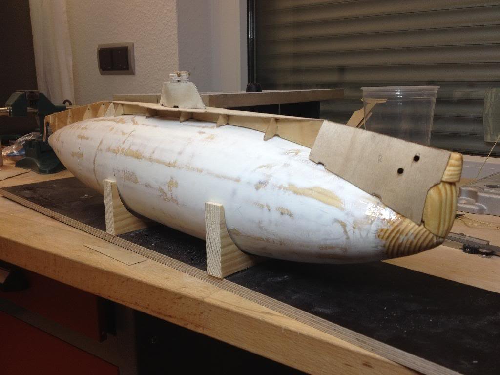
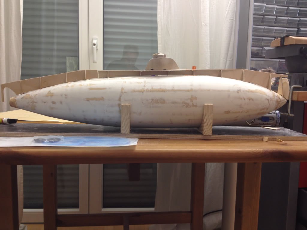
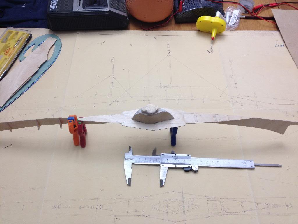
Hi all,
Of course first days of the holiday I have to catch a flu! Poor weather here but at least it gave me some time to work.
The hull is now nice and smooth and I will add another layer of epoxy once I have enough of the superstructure to waterproof that as well.
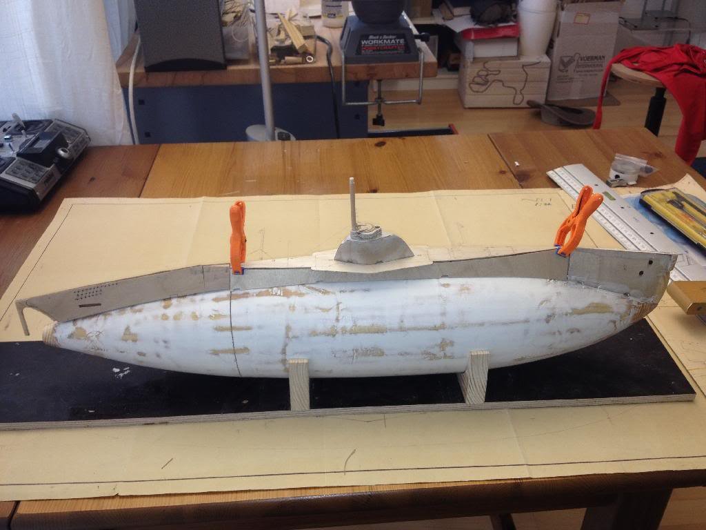
I made some ribs for the deck section and more or less finalised the sail. Here are some overview pictures - the shape of the boat is taking shape!
The front part mounted on the bow is the torpedo tube door which pivoted open (in real life). But there will be so limited room and access in the boat that I decided against making this functional (and I'm no Piet!).
Regards,
Freek
- mtaylor, GrandpaPhil, Piet and 3 others
-
6
-
Very Nice Piet!
Your gun looks much prettier than mine! maybe I can place an order?
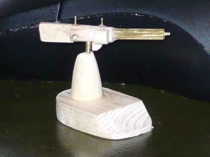
freek
- texxn5, Piet and PacificCrossRoads
-
3
-
I finished planking the hull and after a first layer of epoxy I added two more layers with woven glass fibre to make a strong hull.
Now I used epoxy putty to start evening out the irregularities in the hull. First time sanding after 18 hours gave a reasonable smooth hull though with some of the glass fibre weave still visible. So I just applied the second coat.
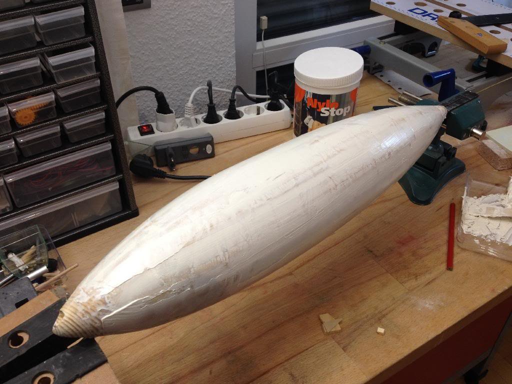
Meanwhile I also started on the superstructure. As the dive tank inside the hull will need a volume equal to displacing all the materials over the waterline, it is important to build the superstructure light.
I used 1.5 mm birch triplex for the frames and 0.8 mm for the hull plates above the waterline. This area needs to flood so I need to ensure the air can go out when the boat submerges.
See attached an outline of the long and narrow superstructure.
and below a detail on the drawing
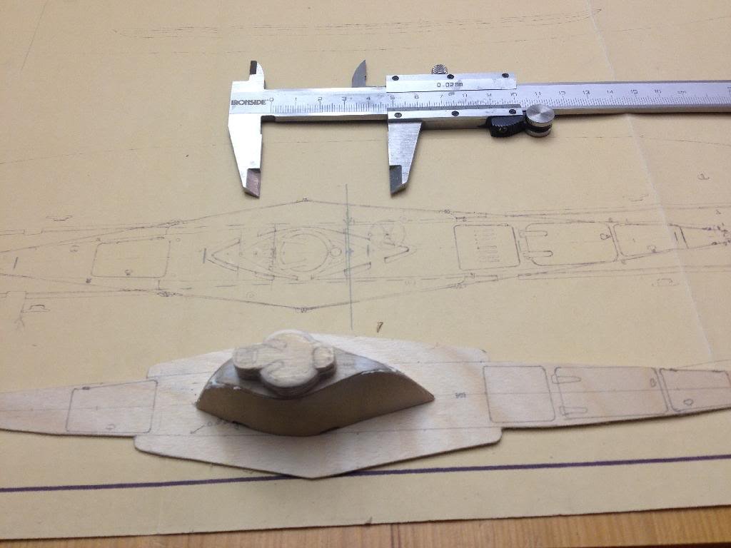
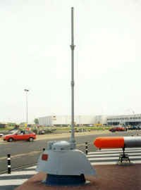
The sail of the original is mounted as a monument in the Dutch navy harbour in Den Helder
Freek
-
Piet,
Surely there is a lot of uncertainty on which 40 mm was placed on which Dutch sub. See below discussion on Dutchsubmarines
http://www.dutchsubmarines.com/pictures/pictures_mystery.htm
On Dutchfleet,the gun on O19 is listed as 40 mm nr 2 (Vickers). That seems to fit with the pictures posted by Boris.
http://www.dutchfleet.net/showthread.php/3867-Dutch-naval-guns
But the uncertainty factor is high and if you have better info that would be interesting for many people.
Freek
- PacificCrossRoads and Piet
-
2
-
Boris , Piet
I found most of thos photos also when I searched for pics for my K-KVIII. I think Boris is right and the mount in the drawings allows the gun to turn vertical and then sink into its bun. I cannot say if the O19 had the same 40 mm as the K-XVIII.
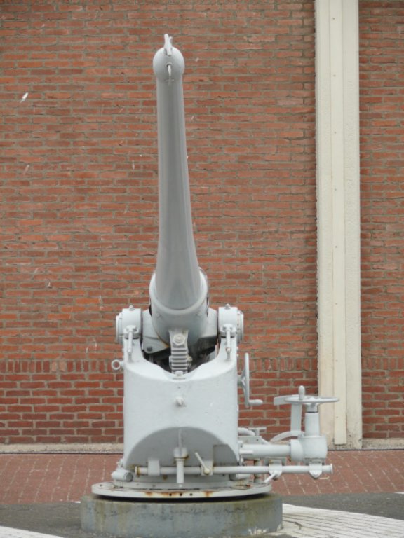
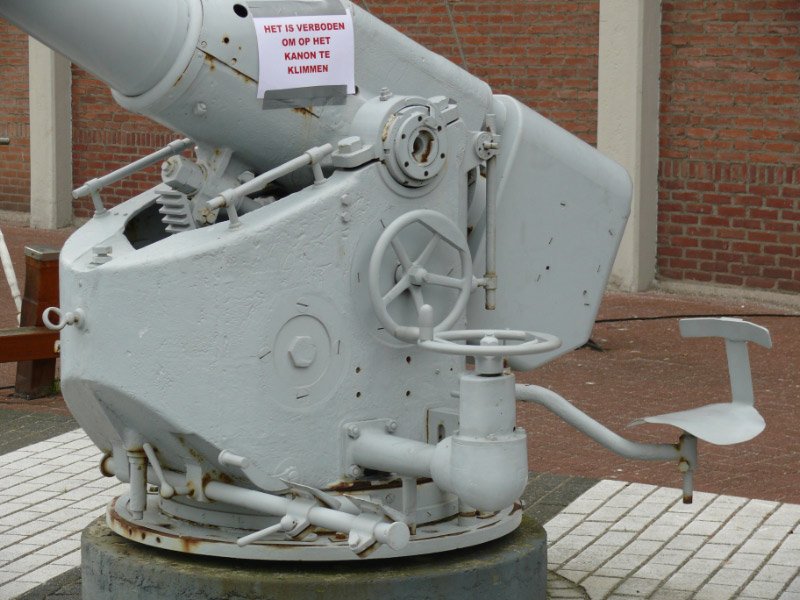
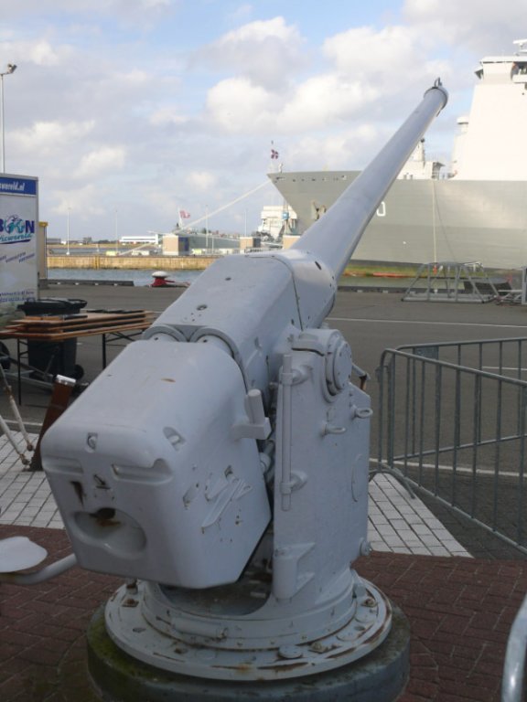
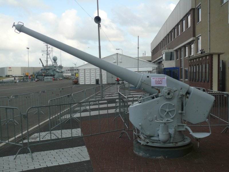
As for the deckgun, two of them are in front of the Navy museum in Den Helder, I believe these guns are from O21 and O24, but are similar or the same as the guns on the older subs.
Freek


Hr. Ms. O 19 1938 by Piet - FINISHED - scale 1:50 - submarine of the Royal Navy Netherlands in service 1939 - 1945
in - Build logs for subjects built 1901 - Present Day
Posted
I think the dingie would be upside down!
Build is fantastic!
Freek