
Supplies of the Ship Modeler's Handbook are running out. Get your copy NOW before they are gone! Click on photo to order.
×

FreekS
-
Posts
213 -
Joined
-
Last visited
Reputation Activity
-

 FreekS got a reaction from Ian_Grant in HrMs O-13 by FreekS - 1:50 - RADIO - 1931-1940 - Last Dutch Sub “on eternal patrol”
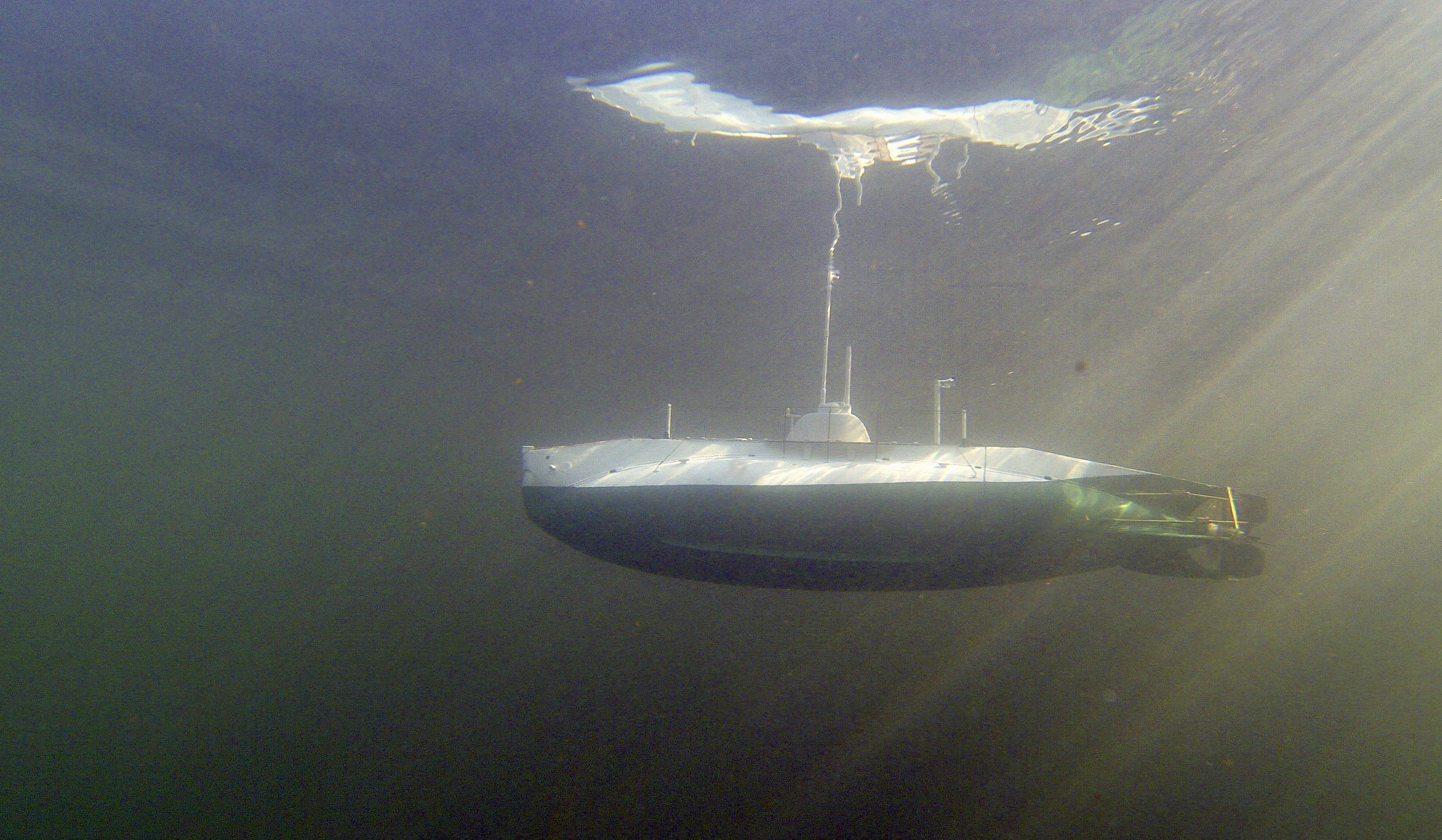
You mean “surfacing after a dive” !
it will be a while….. for O-13, but here is one from my also wooden K-XVIII
-
 FreekS got a reaction from Ian_Grant in HrMs O-13 by FreekS - 1:50 - RADIO - 1931-1940 - Last Dutch Sub “on eternal patrol”
The four parts of the hull have been sanded and I applied first layer of epoxy filler. The basic shape is now done. I want to get the various holes cut in the hull (for flooding, allowing air to escape, and the rudder, planes and prop holes before I epoxy again - so that all wood becomes sealed.
thus I have to plan all “holes” and one of the difficult ones is for the front dive planes at the bow. These planes fold flush against the hull, and are covered by some plating outside the hull.
so I started designing the functionality with the allowed space (tiny). This is the result:
https://youtu.be/hi7XH0Wy4v0?feature=shared
the two yellow gears rotate the common axle of the diveplanes. The axle has a hingepoint to fold each plane. Underneath each hingepoint is a brass gear that turns a pair of messing wires to apply sideways force on the axis outside of the hinges. This turns the diveplanes flush with the hull and back. The two brass gears are coupled through 4 more to work in tandem (could have worked with 2 but they would have had to be bigger and cause conflicts). The large yellow cog and one of the 6 brass cogs will be driven by a servo 4-8 inches further back in the water tight compartment of the boat (this gear assembly will be “in the wet”).
This took me a good few hours of brasswork (of which I learnt a lot) and 3D design and printing (at which I’m also a beginner). I’d like to replace the printed parts with messing but I’m not at all sure I would achieve the precision on the boreholes to make it turn properly. I anyhow need to make another version of this as there is some play in the yellow cogs.
-
FreekS got a reaction from Ian_Grant in HrMs O-13 by FreekS - 1:50 - RADIO - 1931-1940 - Last Dutch Sub “on eternal patrol”
The four pieces came out OK, I coated each one inside and outside with epoxy sealer - mainly to glue all planks together and stabilise the boat against small chips during sanding.
There were a few small places with damage from the saw, and I replaced two small pieces of plank.
Yesterday applied first layer of epoxy putty and stated sanding that back. The boat parts now feel really strong and I can focus on getting the outside shape smoothed.
-
FreekS got a reaction from Ian_Grant in HrMs O-13 by FreekS - 1:50 - RADIO - 1931-1940 - Last Dutch Sub “on eternal patrol”
Reached a milestone in that the planking of the hull is complete!
I cut my planks myself out of pine, they are 4mm wide and 2 mm thick and were cut from 2m by 5cm by 4mm planks. Just needed to avoid the knots in the wood.
the keel of the boat has a thicker area, probably for ballast, as these boats suffered from instability, which is why a deck gun was not included in the class. The keel was not, however, detachable which was common in even older subs.
next step is rough sanding, followed by a first coat of epoxy before splitting the boat as described in a previous post to have access to the inside.
-
 FreekS got a reaction from Ainars in HrMs O-13 by FreekS - 1:50 - RADIO - 1931-1940 - Last Dutch Sub “on eternal patrol”
Started work on the water-tight compartment inside the wooden hull. The hull will flood when dived, and the WTC will contain the motors, batteries, receiver, two-way pump and a 500ml divetank to dive the boat.
The insides of the WTC can be accessed by a bayonet between the aft 50mm diameter PVC tube and the mid 75mm PVC tube.
this is the WTC seen from the stern. The white stern endcap will have two shafts driven by a motor inside the 50mm PVC tube. The holes are where the prop shaft and the rudder and diveplanes seals will come. Between the two white parts of the endcap will come a gearbox to counter rotate the two shafts.
Further forward is the bajonet, seen below when opened.
two M4 bolts on the start section fit into the keyholes (strengthened with brass) in the front section and thus the two boat halves can be twisted shut. The bajonet contains O-rings to seal the 50 and 75mm PVC tubes.
this picture shows the bajonet shut and the bolts holding the two halves together.
And finally with the two deck sections attached.
now that I know exactly where the WTC and its connections will come, I can start to work on the prop shafts and their outholders, the rudder and diveplanes and the holes in the wooden hull to flood the boat and enable air to escape.
-
 FreekS got a reaction from mtaylor in HrMs O-13 by FreekS - 1:50 - RADIO - 1931-1940 - Last Dutch Sub “on eternal patrol”
Started work on the water-tight compartment inside the wooden hull. The hull will flood when dived, and the WTC will contain the motors, batteries, receiver, two-way pump and a 500ml divetank to dive the boat.
The insides of the WTC can be accessed by a bayonet between the aft 50mm diameter PVC tube and the mid 75mm PVC tube.
this is the WTC seen from the stern. The white stern endcap will have two shafts driven by a motor inside the 50mm PVC tube. The holes are where the prop shaft and the rudder and diveplanes seals will come. Between the two white parts of the endcap will come a gearbox to counter rotate the two shafts.
Further forward is the bajonet, seen below when opened.
two M4 bolts on the start section fit into the keyholes (strengthened with brass) in the front section and thus the two boat halves can be twisted shut. The bajonet contains O-rings to seal the 50 and 75mm PVC tubes.
this picture shows the bajonet shut and the bolts holding the two halves together.
And finally with the two deck sections attached.
now that I know exactly where the WTC and its connections will come, I can start to work on the prop shafts and their outholders, the rudder and diveplanes and the holes in the wooden hull to flood the boat and enable air to escape.
-
 FreekS got a reaction from Ryland Craze in HrMs O-13 by FreekS - 1:50 - RADIO - 1931-1940 - Last Dutch Sub “on eternal patrol”
Started work on the water-tight compartment inside the wooden hull. The hull will flood when dived, and the WTC will contain the motors, batteries, receiver, two-way pump and a 500ml divetank to dive the boat.
The insides of the WTC can be accessed by a bayonet between the aft 50mm diameter PVC tube and the mid 75mm PVC tube.
this is the WTC seen from the stern. The white stern endcap will have two shafts driven by a motor inside the 50mm PVC tube. The holes are where the prop shaft and the rudder and diveplanes seals will come. Between the two white parts of the endcap will come a gearbox to counter rotate the two shafts.
Further forward is the bajonet, seen below when opened.
two M4 bolts on the start section fit into the keyholes (strengthened with brass) in the front section and thus the two boat halves can be twisted shut. The bajonet contains O-rings to seal the 50 and 75mm PVC tubes.
this picture shows the bajonet shut and the bolts holding the two halves together.
And finally with the two deck sections attached.
now that I know exactly where the WTC and its connections will come, I can start to work on the prop shafts and their outholders, the rudder and diveplanes and the holes in the wooden hull to flood the boat and enable air to escape.
-
 FreekS got a reaction from _SalD_ in HrMs O-13 by FreekS - 1:50 - RADIO - 1931-1940 - Last Dutch Sub “on eternal patrol”
Started work on the water-tight compartment inside the wooden hull. The hull will flood when dived, and the WTC will contain the motors, batteries, receiver, two-way pump and a 500ml divetank to dive the boat.
The insides of the WTC can be accessed by a bayonet between the aft 50mm diameter PVC tube and the mid 75mm PVC tube.
this is the WTC seen from the stern. The white stern endcap will have two shafts driven by a motor inside the 50mm PVC tube. The holes are where the prop shaft and the rudder and diveplanes seals will come. Between the two white parts of the endcap will come a gearbox to counter rotate the two shafts.
Further forward is the bajonet, seen below when opened.
two M4 bolts on the start section fit into the keyholes (strengthened with brass) in the front section and thus the two boat halves can be twisted shut. The bajonet contains O-rings to seal the 50 and 75mm PVC tubes.
this picture shows the bajonet shut and the bolts holding the two halves together.
And finally with the two deck sections attached.
now that I know exactly where the WTC and its connections will come, I can start to work on the prop shafts and their outholders, the rudder and diveplanes and the holes in the wooden hull to flood the boat and enable air to escape.
-
FreekS got a reaction from Ian_Grant in HrMs O-13 by FreekS - 1:50 - RADIO - 1931-1940 - Last Dutch Sub “on eternal patrol”
Started work on the water-tight compartment inside the wooden hull. The hull will flood when dived, and the WTC will contain the motors, batteries, receiver, two-way pump and a 500ml divetank to dive the boat.
The insides of the WTC can be accessed by a bayonet between the aft 50mm diameter PVC tube and the mid 75mm PVC tube.
this is the WTC seen from the stern. The white stern endcap will have two shafts driven by a motor inside the 50mm PVC tube. The holes are where the prop shaft and the rudder and diveplanes seals will come. Between the two white parts of the endcap will come a gearbox to counter rotate the two shafts.
Further forward is the bajonet, seen below when opened.
two M4 bolts on the start section fit into the keyholes (strengthened with brass) in the front section and thus the two boat halves can be twisted shut. The bajonet contains O-rings to seal the 50 and 75mm PVC tubes.
this picture shows the bajonet shut and the bolts holding the two halves together.
And finally with the two deck sections attached.
now that I know exactly where the WTC and its connections will come, I can start to work on the prop shafts and their outholders, the rudder and diveplanes and the holes in the wooden hull to flood the boat and enable air to escape.
-
 FreekS got a reaction from KeithAug in HrMs O-13 by FreekS - 1:50 - RADIO - 1931-1940 - Last Dutch Sub “on eternal patrol”
The four parts of the hull have been sanded and I applied first layer of epoxy filler. The basic shape is now done. I want to get the various holes cut in the hull (for flooding, allowing air to escape, and the rudder, planes and prop holes before I epoxy again - so that all wood becomes sealed.
thus I have to plan all “holes” and one of the difficult ones is for the front dive planes at the bow. These planes fold flush against the hull, and are covered by some plating outside the hull.
so I started designing the functionality with the allowed space (tiny). This is the result:
https://youtu.be/hi7XH0Wy4v0?feature=shared
the two yellow gears rotate the common axle of the diveplanes. The axle has a hingepoint to fold each plane. Underneath each hingepoint is a brass gear that turns a pair of messing wires to apply sideways force on the axis outside of the hinges. This turns the diveplanes flush with the hull and back. The two brass gears are coupled through 4 more to work in tandem (could have worked with 2 but they would have had to be bigger and cause conflicts). The large yellow cog and one of the 6 brass cogs will be driven by a servo 4-8 inches further back in the water tight compartment of the boat (this gear assembly will be “in the wet”).
This took me a good few hours of brasswork (of which I learnt a lot) and 3D design and printing (at which I’m also a beginner). I’d like to replace the printed parts with messing but I’m not at all sure I would achieve the precision on the boreholes to make it turn properly. I anyhow need to make another version of this as there is some play in the yellow cogs.
-
 FreekS got a reaction from Canute in HrMs O-13 by FreekS - 1:50 - RADIO - 1931-1940 - Last Dutch Sub “on eternal patrol”
Started work on the water-tight compartment inside the wooden hull. The hull will flood when dived, and the WTC will contain the motors, batteries, receiver, two-way pump and a 500ml divetank to dive the boat.
The insides of the WTC can be accessed by a bayonet between the aft 50mm diameter PVC tube and the mid 75mm PVC tube.
this is the WTC seen from the stern. The white stern endcap will have two shafts driven by a motor inside the 50mm PVC tube. The holes are where the prop shaft and the rudder and diveplanes seals will come. Between the two white parts of the endcap will come a gearbox to counter rotate the two shafts.
Further forward is the bajonet, seen below when opened.
two M4 bolts on the start section fit into the keyholes (strengthened with brass) in the front section and thus the two boat halves can be twisted shut. The bajonet contains O-rings to seal the 50 and 75mm PVC tubes.
this picture shows the bajonet shut and the bolts holding the two halves together.
And finally with the two deck sections attached.
now that I know exactly where the WTC and its connections will come, I can start to work on the prop shafts and their outholders, the rudder and diveplanes and the holes in the wooden hull to flood the boat and enable air to escape.
-
FreekS got a reaction from Canute in HrMs O-13 by FreekS - 1:50 - RADIO - 1931-1940 - Last Dutch Sub “on eternal patrol”
You mean “surfacing after a dive” !
it will be a while….. for O-13, but here is one from my also wooden K-XVIII
-
 FreekS got a reaction from GrandpaPhil in HrMs O-13 by FreekS - 1:50 - RADIO - 1931-1940 - Last Dutch Sub “on eternal patrol”
You mean “surfacing after a dive” !
it will be a while….. for O-13, but here is one from my also wooden K-XVIII
-
 FreekS got a reaction from yvesvidal in HrMs O-13 by FreekS - 1:50 - RADIO - 1931-1940 - Last Dutch Sub “on eternal patrol”
You mean “surfacing after a dive” !
it will be a while….. for O-13, but here is one from my also wooden K-XVIII
-
 FreekS got a reaction from Roger Pellett in HrMs O-13 by FreekS - 1:50 - RADIO - 1931-1940 - Last Dutch Sub “on eternal patrol”
You mean “surfacing after a dive” !
it will be a while….. for O-13, but here is one from my also wooden K-XVIII
-
FreekS got a reaction from mtaylor in HrMs O-13 by FreekS - 1:50 - RADIO - 1931-1940 - Last Dutch Sub “on eternal patrol”
You mean “surfacing after a dive” !
it will be a while….. for O-13, but here is one from my also wooden K-XVIII
-
FreekS got a reaction from mtaylor in HrMs O-13 by FreekS - 1:50 - RADIO - 1931-1940 - Last Dutch Sub “on eternal patrol”
The four parts of the hull have been sanded and I applied first layer of epoxy filler. The basic shape is now done. I want to get the various holes cut in the hull (for flooding, allowing air to escape, and the rudder, planes and prop holes before I epoxy again - so that all wood becomes sealed.
thus I have to plan all “holes” and one of the difficult ones is for the front dive planes at the bow. These planes fold flush against the hull, and are covered by some plating outside the hull.
so I started designing the functionality with the allowed space (tiny). This is the result:
https://youtu.be/hi7XH0Wy4v0?feature=shared
the two yellow gears rotate the common axle of the diveplanes. The axle has a hingepoint to fold each plane. Underneath each hingepoint is a brass gear that turns a pair of messing wires to apply sideways force on the axis outside of the hinges. This turns the diveplanes flush with the hull and back. The two brass gears are coupled through 4 more to work in tandem (could have worked with 2 but they would have had to be bigger and cause conflicts). The large yellow cog and one of the 6 brass cogs will be driven by a servo 4-8 inches further back in the water tight compartment of the boat (this gear assembly will be “in the wet”).
This took me a good few hours of brasswork (of which I learnt a lot) and 3D design and printing (at which I’m also a beginner). I’d like to replace the printed parts with messing but I’m not at all sure I would achieve the precision on the boreholes to make it turn properly. I anyhow need to make another version of this as there is some play in the yellow cogs.
-
FreekS got a reaction from yvesvidal in HrMs O-13 by FreekS - 1:50 - RADIO - 1931-1940 - Last Dutch Sub “on eternal patrol”
The four pieces came out OK, I coated each one inside and outside with epoxy sealer - mainly to glue all planks together and stabilise the boat against small chips during sanding.
There were a few small places with damage from the saw, and I replaced two small pieces of plank.
Yesterday applied first layer of epoxy putty and stated sanding that back. The boat parts now feel really strong and I can focus on getting the outside shape smoothed.
-
FreekS got a reaction from GrandpaPhil in HrMs O-13 by FreekS - 1:50 - RADIO - 1931-1940 - Last Dutch Sub “on eternal patrol”
The four parts of the hull have been sanded and I applied first layer of epoxy filler. The basic shape is now done. I want to get the various holes cut in the hull (for flooding, allowing air to escape, and the rudder, planes and prop holes before I epoxy again - so that all wood becomes sealed.
thus I have to plan all “holes” and one of the difficult ones is for the front dive planes at the bow. These planes fold flush against the hull, and are covered by some plating outside the hull.
so I started designing the functionality with the allowed space (tiny). This is the result:
https://youtu.be/hi7XH0Wy4v0?feature=shared
the two yellow gears rotate the common axle of the diveplanes. The axle has a hingepoint to fold each plane. Underneath each hingepoint is a brass gear that turns a pair of messing wires to apply sideways force on the axis outside of the hinges. This turns the diveplanes flush with the hull and back. The two brass gears are coupled through 4 more to work in tandem (could have worked with 2 but they would have had to be bigger and cause conflicts). The large yellow cog and one of the 6 brass cogs will be driven by a servo 4-8 inches further back in the water tight compartment of the boat (this gear assembly will be “in the wet”).
This took me a good few hours of brasswork (of which I learnt a lot) and 3D design and printing (at which I’m also a beginner). I’d like to replace the printed parts with messing but I’m not at all sure I would achieve the precision on the boreholes to make it turn properly. I anyhow need to make another version of this as there is some play in the yellow cogs.
-
FreekS got a reaction from Canute in HrMs O-13 by FreekS - 1:50 - RADIO - 1931-1940 - Last Dutch Sub “on eternal patrol”
The four parts of the hull have been sanded and I applied first layer of epoxy filler. The basic shape is now done. I want to get the various holes cut in the hull (for flooding, allowing air to escape, and the rudder, planes and prop holes before I epoxy again - so that all wood becomes sealed.
thus I have to plan all “holes” and one of the difficult ones is for the front dive planes at the bow. These planes fold flush against the hull, and are covered by some plating outside the hull.
so I started designing the functionality with the allowed space (tiny). This is the result:
https://youtu.be/hi7XH0Wy4v0?feature=shared
the two yellow gears rotate the common axle of the diveplanes. The axle has a hingepoint to fold each plane. Underneath each hingepoint is a brass gear that turns a pair of messing wires to apply sideways force on the axis outside of the hinges. This turns the diveplanes flush with the hull and back. The two brass gears are coupled through 4 more to work in tandem (could have worked with 2 but they would have had to be bigger and cause conflicts). The large yellow cog and one of the 6 brass cogs will be driven by a servo 4-8 inches further back in the water tight compartment of the boat (this gear assembly will be “in the wet”).
This took me a good few hours of brasswork (of which I learnt a lot) and 3D design and printing (at which I’m also a beginner). I’d like to replace the printed parts with messing but I’m not at all sure I would achieve the precision on the boreholes to make it turn properly. I anyhow need to make another version of this as there is some play in the yellow cogs.
-
FreekS reacted to mikegr in Type 45 Destroyer by mikegr - FINISHED - 1/700
I printed most of the parts.Since I used a plan to calculate the size of the pieces and the PE parts are made to replace standard plastic parts of specific kits some misfitting is expected. Some PEs won't be used as the required details is already designed at the parts I printed.
-
FreekS reacted to mikegr in Type 45 Destroyer by mikegr - FINISHED - 1/700
Today I painted the dark grey and added some PE after the proper adjustments
-
FreekS got a reaction from Canute in HrMs O-13 by FreekS - 1:50 - RADIO - 1931-1940 - Last Dutch Sub “on eternal patrol”
The four pieces came out OK, I coated each one inside and outside with epoxy sealer - mainly to glue all planks together and stabilise the boat against small chips during sanding.
There were a few small places with damage from the saw, and I replaced two small pieces of plank.
Yesterday applied first layer of epoxy putty and stated sanding that back. The boat parts now feel really strong and I can focus on getting the outside shape smoothed.
-
FreekS got a reaction from mtaylor in HrMs O-13 by FreekS - 1:50 - RADIO - 1931-1940 - Last Dutch Sub “on eternal patrol”
The four pieces came out OK, I coated each one inside and outside with epoxy sealer - mainly to glue all planks together and stabilise the boat against small chips during sanding.
There were a few small places with damage from the saw, and I replaced two small pieces of plank.
Yesterday applied first layer of epoxy putty and stated sanding that back. The boat parts now feel really strong and I can focus on getting the outside shape smoothed.