
Supplies of the Ship Modeler's Handbook are running out. Get your copy NOW before they are gone! Click on photo to order.
×

FreekS
-
Posts
213 -
Joined
-
Last visited
Reputation Activity
-

 FreekS got a reaction from Harvey Golden in HrMs O-13 by FreekS - 1:50 - RADIO - 1931-1940 - Last Dutch Sub “on eternal patrol”
All frames now glued to the keel, and I inserted small sticks between the frames which gives the hull rigidity.
Before planking, I have to assure myself I can install the rudder/diveplanes assembly in the stern, and the bow planes in the bow. The boat is so narrow at this points (around 2cm), that I have to have a clear idea of the controls on the planes and rudders before closing the hull!!
started with the bow planes, which as the photo on the 1st post shows, rotate upwards and then fold back when the sub is on the surface. I made a brass assembly where two cogwheels control the dive angle and the vertical rotation, and then a pushrod can fold the planes against the hull.
it sort of works, but I have a long list of modifications before I can make a true prototype. And yes, the planes themselves will get shaped!
-
 FreekS got a reaction from yvesvidal in HrMs O-13 by FreekS - 1:50 - RADIO - 1931-1940 - Last Dutch Sub “on eternal patrol”
All frames now glued to the keel, and I inserted small sticks between the frames which gives the hull rigidity.
Before planking, I have to assure myself I can install the rudder/diveplanes assembly in the stern, and the bow planes in the bow. The boat is so narrow at this points (around 2cm), that I have to have a clear idea of the controls on the planes and rudders before closing the hull!!
started with the bow planes, which as the photo on the 1st post shows, rotate upwards and then fold back when the sub is on the surface. I made a brass assembly where two cogwheels control the dive angle and the vertical rotation, and then a pushrod can fold the planes against the hull.
it sort of works, but I have a long list of modifications before I can make a true prototype. And yes, the planes themselves will get shaped!
-
 FreekS got a reaction from KeithAug in HrMs O-13 by FreekS - 1:50 - RADIO - 1931-1940 - Last Dutch Sub “on eternal patrol”
All frames now glued to the keel, and I inserted small sticks between the frames which gives the hull rigidity.
Before planking, I have to assure myself I can install the rudder/diveplanes assembly in the stern, and the bow planes in the bow. The boat is so narrow at this points (around 2cm), that I have to have a clear idea of the controls on the planes and rudders before closing the hull!!
started with the bow planes, which as the photo on the 1st post shows, rotate upwards and then fold back when the sub is on the surface. I made a brass assembly where two cogwheels control the dive angle and the vertical rotation, and then a pushrod can fold the planes against the hull.
it sort of works, but I have a long list of modifications before I can make a true prototype. And yes, the planes themselves will get shaped!
-
FreekS got a reaction from KeithAug in HrMs O-13 by FreekS - 1:50 - RADIO - 1931-1940 - Last Dutch Sub “on eternal patrol”
I finished the sawing of the frames, and placed the half-frames loose on the “keel”. It’s clearly a more difficult shape, with the saddletanks in the middle and a suddenly widening keel below them. I also had to take into account the space for the watertight cylinders and for the prop axes as drilling will be harder once the hull is planked. the two thicker frames is where the hull will be cut to access the insides.
-
FreekS reacted to Ikcdab in Wattle by Ikcdab - 1:24 - Steam Tug - my first scratchbuild
So I have now cut out all of the bulkheads.
Just temporarily stood up....
-
FreekS got a reaction from yvesvidal in HrMs O-13 by FreekS - 1:50 - RADIO - 1931-1940 - Last Dutch Sub “on eternal patrol”
I finished the sawing of the frames, and placed the half-frames loose on the “keel”. It’s clearly a more difficult shape, with the saddletanks in the middle and a suddenly widening keel below them. I also had to take into account the space for the watertight cylinders and for the prop axes as drilling will be harder once the hull is planked. the two thicker frames is where the hull will be cut to access the insides.
-
 FreekS got a reaction from mtaylor in HrMs O-13 by FreekS - 1:50 - RADIO - 1931-1940 - Last Dutch Sub “on eternal patrol”
I finished the sawing of the frames, and placed the half-frames loose on the “keel”. It’s clearly a more difficult shape, with the saddletanks in the middle and a suddenly widening keel below them. I also had to take into account the space for the watertight cylinders and for the prop axes as drilling will be harder once the hull is planked. the two thicker frames is where the hull will be cut to access the insides.
-
 FreekS got a reaction from Canute in HrMs O-13 by FreekS - 1:50 - RADIO - 1931-1940 - Last Dutch Sub “on eternal patrol”
I finished the sawing of the frames, and placed the half-frames loose on the “keel”. It’s clearly a more difficult shape, with the saddletanks in the middle and a suddenly widening keel below them. I also had to take into account the space for the watertight cylinders and for the prop axes as drilling will be harder once the hull is planked. the two thicker frames is where the hull will be cut to access the insides.
-
FreekS reacted to Ikcdab in Wattle by Ikcdab - 1:24 - Steam Tug - my first scratchbuild
So tonight I am going to reprint the rudder. The screenshot below shows that I have added a sacrificial "sprue" along the bottom edge in order to try and keep the rudder from warping on the build plate. You can also see that I am going to print the remaining hatches and, hidden behind the rudder, is the motormount.
Its a 9 hour print, so Ill run it overnight. Lets hope this one is more successful....
-
 FreekS got a reaction from Keith Black in Wattle by Ikcdab - 1:24 - Steam Tug - my first scratchbuild
We all struggle with these calculations!
there are some formulas that convert prop rpm and pitch into speed, and like roger I suspect at a few 1000 rpm the prop will deliver the max speed that hull can reach. The hard calculation is if the motor can deliver the torque to the prop under load. I suspect your motor can only do that if you use a gearbox (dropping Reva for more torque). Dropping the voltage on a brushed motor will drop torque. Brushed motors like to run at their rated rpm. but on a brushless motor which typically has ample torque that is exactly what you do. These have kV indications, being rpm per volt, so a 1000kV brushless motor at 12 volt delivers 12000 rpm (too much) so you could run that at lower voltage. You likely would need a 300-700kV brushless motor.
I would couple a shaft and prop to your motor in a test rig, hook it up to a ESC and test if it runs and does not get too hot (and how much power it draws).
-
FreekS got a reaction from Canute in Wattle by Ikcdab - 1:24 - Steam Tug - my first scratchbuild
I’m not an expert on tugs but I estimate yours will be 1 meter long and weigh maybe 7 kg? (99 tonnes/24^3). I think that prop will provide massive power at under 5000rpm.
Then you might consider a gearbox or drivebelt with a 1:3 reduction. Takes more space and risk of noise if not done well.
you will need an electronic speed controller (with reverse!) and that unit and the motor can get really hot if prop and motor (and voltage) are poorly matched. You can cool them but that is wasting power. When you have the speed controller and a cheap servotester you can test the current draw and heat generation in a bath or sink.
Alternatively you can buy a brushless motor which are much smaller for the torque (but take care that they need a different type of speed controller)
sorry, this sounds difficult (or different from trains), but testing the voltage/current/motor/prop combination before building them into your ship is worthwhile.
-
FreekS got a reaction from Canute in Wattle by Ikcdab - 1:24 - Steam Tug - my first scratchbuild
Nice build!
you will find (or calculate) that you will need quite a bit of ballast. Then lead-acid is fine provided it’s a sealed unit.
looks like you don’t need much current. If 1,5A works (test in bath for waves produced with that prop, the 5Ah would give you three hours of run time.
As there is no benefit for low weight and high currents of Lipo, stay away from them. I use them in subs where space is a premium.
I also successfully used 2x10 eneloop AAA to get 12-14V. Big advantage (these are a special type of NiMH) is that these have no memory and hold charge perfectly over storage.
Finally, Li-ion also has lots of very good cells (3.7V 5000mAh).
If you make sure you speed controller has a low battery alarm than these are widely available and cheap.
something you do need to research is the match of the motor to the prop. 90mm props will put a lot of torque on the motor. For brushed motors rule of thumb is that diameter of motor should be about same as that of prop. For brushless that does not hold, the have massive power.
-
FreekS got a reaction from mtaylor in Wattle by Ikcdab - 1:24 - Steam Tug - my first scratchbuild
We all struggle with these calculations!
there are some formulas that convert prop rpm and pitch into speed, and like roger I suspect at a few 1000 rpm the prop will deliver the max speed that hull can reach. The hard calculation is if the motor can deliver the torque to the prop under load. I suspect your motor can only do that if you use a gearbox (dropping Reva for more torque). Dropping the voltage on a brushed motor will drop torque. Brushed motors like to run at their rated rpm. but on a brushless motor which typically has ample torque that is exactly what you do. These have kV indications, being rpm per volt, so a 1000kV brushless motor at 12 volt delivers 12000 rpm (too much) so you could run that at lower voltage. You likely would need a 300-700kV brushless motor.
I would couple a shaft and prop to your motor in a test rig, hook it up to a ESC and test if it runs and does not get too hot (and how much power it draws).
-
FreekS got a reaction from mtaylor in Wattle by Ikcdab - 1:24 - Steam Tug - my first scratchbuild
I’m not an expert on tugs but I estimate yours will be 1 meter long and weigh maybe 7 kg? (99 tonnes/24^3). I think that prop will provide massive power at under 5000rpm.
Then you might consider a gearbox or drivebelt with a 1:3 reduction. Takes more space and risk of noise if not done well.
you will need an electronic speed controller (with reverse!) and that unit and the motor can get really hot if prop and motor (and voltage) are poorly matched. You can cool them but that is wasting power. When you have the speed controller and a cheap servotester you can test the current draw and heat generation in a bath or sink.
Alternatively you can buy a brushless motor which are much smaller for the torque (but take care that they need a different type of speed controller)
sorry, this sounds difficult (or different from trains), but testing the voltage/current/motor/prop combination before building them into your ship is worthwhile.
-
FreekS got a reaction from mtaylor in Wattle by Ikcdab - 1:24 - Steam Tug - my first scratchbuild
Nice build!
you will find (or calculate) that you will need quite a bit of ballast. Then lead-acid is fine provided it’s a sealed unit.
looks like you don’t need much current. If 1,5A works (test in bath for waves produced with that prop, the 5Ah would give you three hours of run time.
As there is no benefit for low weight and high currents of Lipo, stay away from them. I use them in subs where space is a premium.
I also successfully used 2x10 eneloop AAA to get 12-14V. Big advantage (these are a special type of NiMH) is that these have no memory and hold charge perfectly over storage.
Finally, Li-ion also has lots of very good cells (3.7V 5000mAh).
If you make sure you speed controller has a low battery alarm than these are widely available and cheap.
something you do need to research is the match of the motor to the prop. 90mm props will put a lot of torque on the motor. For brushed motors rule of thumb is that diameter of motor should be about same as that of prop. For brushless that does not hold, the have massive power.
-
FreekS got a reaction from yvesvidal in HrMs O-13 by FreekS - 1:50 - RADIO - 1931-1940 - Last Dutch Sub “on eternal patrol”
Started converting the concept drawing into a 1:50 plan. I’ve not made too many plank on frame models, normally I’d mount the frames on a build plank upside down. With this submarine planking has to go all the way around, so a build plank seems not too useful.
I therefore cut a “keel/deck support plank” (no idea if there is a name for this) and will glue the frames to this plank.
the keel is 8mm thick and the shown frame 44 also, as that is where the hull will be cut later to have access to the inside, so I need some strength in that area. I’ll likely double that frame at least. . .
this was also sort of a test frame if I can cut the frame from the print, transfer it to both halves of the wood and saw it out accurately. Took quite some time - maybe I’ll try gluing the paper to the wood first.
The other frames will be 4mm thick and after all frames are mounted I will connect them first with inserted short wood pieces to end up with a rigid (and hopefully straight) hull. I did that once before and it worked but for a shorter and simpler hull
(so this was the basis of my Holland class sub, with much simpler circular frames)
-
FreekS got a reaction from Keith Black in Wattle by Ikcdab - 1:24 - Steam Tug - my first scratchbuild
Nice build!
you will find (or calculate) that you will need quite a bit of ballast. Then lead-acid is fine provided it’s a sealed unit.
looks like you don’t need much current. If 1,5A works (test in bath for waves produced with that prop, the 5Ah would give you three hours of run time.
As there is no benefit for low weight and high currents of Lipo, stay away from them. I use them in subs where space is a premium.
I also successfully used 2x10 eneloop AAA to get 12-14V. Big advantage (these are a special type of NiMH) is that these have no memory and hold charge perfectly over storage.
Finally, Li-ion also has lots of very good cells (3.7V 5000mAh).
If you make sure you speed controller has a low battery alarm than these are widely available and cheap.
something you do need to research is the match of the motor to the prop. 90mm props will put a lot of torque on the motor. For brushed motors rule of thumb is that diameter of motor should be about same as that of prop. For brushless that does not hold, the have massive power.
-
FreekS got a reaction from Keith Black in Wattle by Ikcdab - 1:24 - Steam Tug - my first scratchbuild
I’m not an expert on tugs but I estimate yours will be 1 meter long and weigh maybe 7 kg? (99 tonnes/24^3). I think that prop will provide massive power at under 5000rpm.
Then you might consider a gearbox or drivebelt with a 1:3 reduction. Takes more space and risk of noise if not done well.
you will need an electronic speed controller (with reverse!) and that unit and the motor can get really hot if prop and motor (and voltage) are poorly matched. You can cool them but that is wasting power. When you have the speed controller and a cheap servotester you can test the current draw and heat generation in a bath or sink.
Alternatively you can buy a brushless motor which are much smaller for the torque (but take care that they need a different type of speed controller)
sorry, this sounds difficult (or different from trains), but testing the voltage/current/motor/prop combination before building them into your ship is worthwhile.
-
FreekS got a reaction from mtaylor in HrMs O-13 by FreekS - 1:50 - RADIO - 1931-1940 - Last Dutch Sub “on eternal patrol”
Started converting the concept drawing into a 1:50 plan. I’ve not made too many plank on frame models, normally I’d mount the frames on a build plank upside down. With this submarine planking has to go all the way around, so a build plank seems not too useful.
I therefore cut a “keel/deck support plank” (no idea if there is a name for this) and will glue the frames to this plank.
the keel is 8mm thick and the shown frame 44 also, as that is where the hull will be cut later to have access to the inside, so I need some strength in that area. I’ll likely double that frame at least. . .
this was also sort of a test frame if I can cut the frame from the print, transfer it to both halves of the wood and saw it out accurately. Took quite some time - maybe I’ll try gluing the paper to the wood first.
The other frames will be 4mm thick and after all frames are mounted I will connect them first with inserted short wood pieces to end up with a rigid (and hopefully straight) hull. I did that once before and it worked but for a shorter and simpler hull
(so this was the basis of my Holland class sub, with much simpler circular frames)
-
 FreekS got a reaction from GrandpaPhil in HrMs O-13 by FreekS - 1:50 - RADIO - 1931-1940 - Last Dutch Sub “on eternal patrol”
Started converting the concept drawing into a 1:50 plan. I’ve not made too many plank on frame models, normally I’d mount the frames on a build plank upside down. With this submarine planking has to go all the way around, so a build plank seems not too useful.
I therefore cut a “keel/deck support plank” (no idea if there is a name for this) and will glue the frames to this plank.
the keel is 8mm thick and the shown frame 44 also, as that is where the hull will be cut later to have access to the inside, so I need some strength in that area. I’ll likely double that frame at least. . .
this was also sort of a test frame if I can cut the frame from the print, transfer it to both halves of the wood and saw it out accurately. Took quite some time - maybe I’ll try gluing the paper to the wood first.
The other frames will be 4mm thick and after all frames are mounted I will connect them first with inserted short wood pieces to end up with a rigid (and hopefully straight) hull. I did that once before and it worked but for a shorter and simpler hull
(so this was the basis of my Holland class sub, with much simpler circular frames)
-
FreekS got a reaction from Canute in HrMs O-13 by FreekS - 1:50 - RADIO - 1931-1940 - Last Dutch Sub “on eternal patrol”
Started converting the concept drawing into a 1:50 plan. I’ve not made too many plank on frame models, normally I’d mount the frames on a build plank upside down. With this submarine planking has to go all the way around, so a build plank seems not too useful.
I therefore cut a “keel/deck support plank” (no idea if there is a name for this) and will glue the frames to this plank.
the keel is 8mm thick and the shown frame 44 also, as that is where the hull will be cut later to have access to the inside, so I need some strength in that area. I’ll likely double that frame at least. . .
this was also sort of a test frame if I can cut the frame from the print, transfer it to both halves of the wood and saw it out accurately. Took quite some time - maybe I’ll try gluing the paper to the wood first.
The other frames will be 4mm thick and after all frames are mounted I will connect them first with inserted short wood pieces to end up with a rigid (and hopefully straight) hull. I did that once before and it worked but for a shorter and simpler hull
(so this was the basis of my Holland class sub, with much simpler circular frames)
-
 FreekS reacted to Richard44 in HrMs O-13 by FreekS - 1:50 - RADIO - 1931-1940 - Last Dutch Sub “on eternal patrol”
Hi,
Another one of the Dutch subs, K XII, was wrecked on Fairlight beach, Sydney Harbour, in June 1949 after breaking its tow. It became a RAN vessel in 1943, but never saw service. It was moored alongside a pier at Manly wharf as a tourist attraction, but was being moved to a more sheltered site during a storm when it broke its tow.
I well remember seeing it on the rocks - Fairlight was my local beach.
Cheers
https://www.flickr.com/photos/41311545@N05/5230854984
-
 FreekS got a reaction from Rik Thistle in HrMs O-13 by FreekS - 1:50 - RADIO - 1931-1940 - Last Dutch Sub “on eternal patrol”
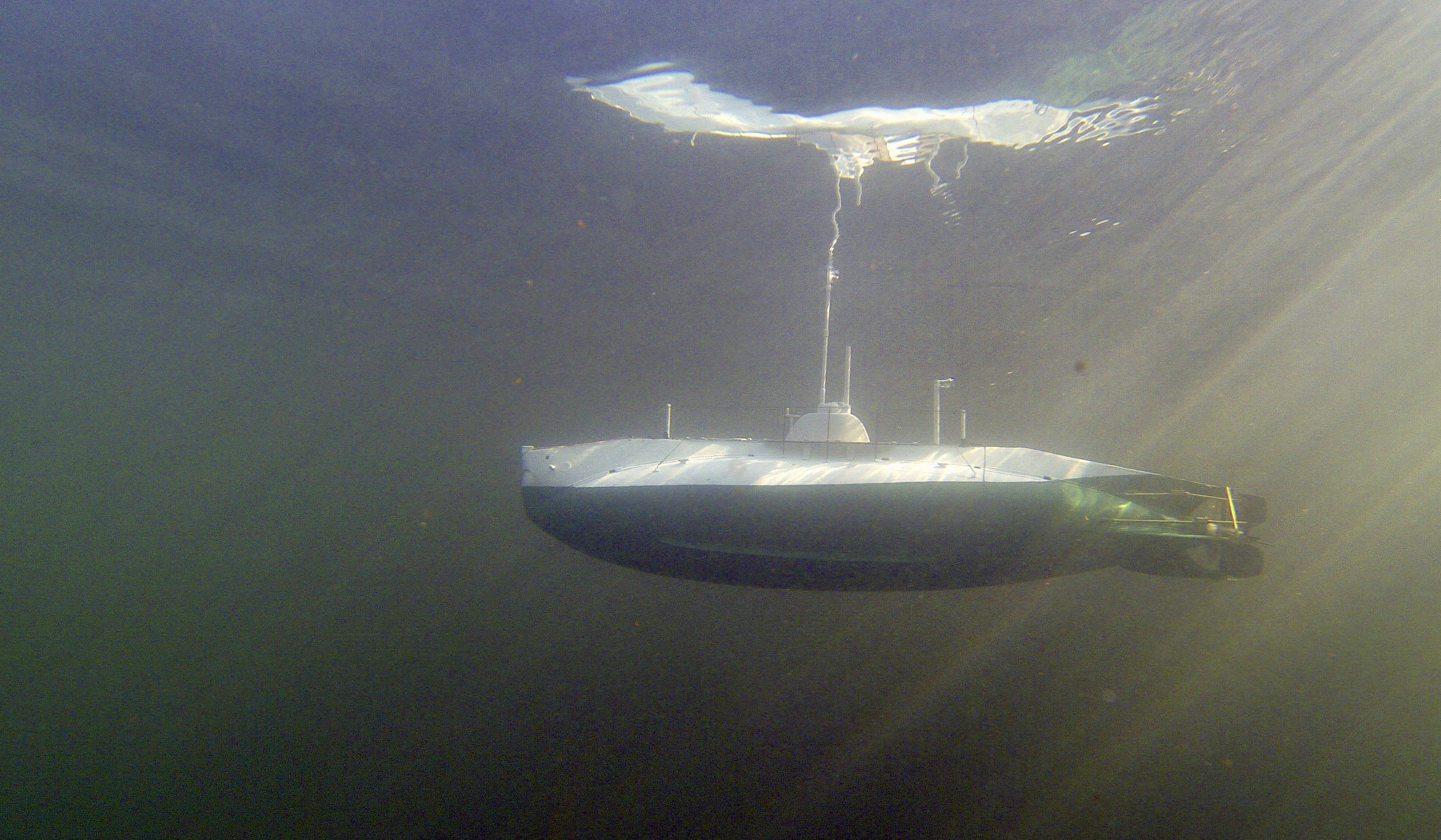
I’m just starting this new project. Netherlands started WW2 with 23 submarines, split evenly between Netherlands-based and Dutch East Indies based. Seven of these subs were lost. O-13 first saw action in the Spanish civil war escorting ships, and then escaped from Netherlands to England in May 1040 with many other boats. However, already in June 1940 on her second war patrol in the waters between Norway and Denmark she failed to return. To this day the wreck has not been found, but every few years there are searches with newer equipment. The most likely cause of her loss is being struck by a mine in a (now known) minefield along her route, but also attacks by German aircraft and a collision with a Polish sub are remote possibilities.
This model will be radio controlled, and the boat will be in-between my Holland-class O-1 (the first sub in the Dutch navy) and the larger K-XVIII which fought the Japanese in Asian waters. Both those models still sail regularly and well.
O-13 was part of a class of 4, at 60 meters in length and with underwater displacement of 750 tons she was suitable for coastal waters, but also travelled to the Dutch islands in the Caribbean and the waters around Gibraltar. She had 4 torpedo tubes in the bow, one in the stern, and two 40mm guns retracting into buns. No deck gun was installed and some of the 40mm guns were removed as the class had significant stability issues.
I have the original build plans (which can be downloaded freely from the Dutch national archives), but photos, especially dock-photos are relatively rare.
I plan to build a traditional plank on frame wooden hull, impregnated with epoxy and coated with woven glass. Inside will be a watertight compartment made up of several connected tubes to house the technology to fill and empty the dive tank, and to control the two props, rudder and diveplanes. I hope to include running lights in the wet area and also attempt to functionalisme the folding forward dive planes visible in the picture. Due to space constraints I will not aim to make moving periscopes and functioning torpedo’s for this model. In the end the model will be 120cm long, 13cm wide at its widest point, likely weigh 3-5kg, and use tubing of 50 and 75 mm diameter as water tight compartment.
So far, I’ve been doing rough planning of the location of components, closure means, and rough calculations of the required size of the dive tank to achieve a realistic waterline. I’ve also started to convert the build plans to individual frame drawings (taking into account the thickness of the hull planks (2mm) and the need to mount the frames on a build plank). Needless to say - this will not be a quick build!
-
FreekS got a reaction from KeithAug in HrMs O-13 by FreekS - 1:50 - RADIO - 1931-1940 - Last Dutch Sub “on eternal patrol”
I’m just starting this new project. Netherlands started WW2 with 23 submarines, split evenly between Netherlands-based and Dutch East Indies based. Seven of these subs were lost. O-13 first saw action in the Spanish civil war escorting ships, and then escaped from Netherlands to England in May 1040 with many other boats. However, already in June 1940 on her second war patrol in the waters between Norway and Denmark she failed to return. To this day the wreck has not been found, but every few years there are searches with newer equipment. The most likely cause of her loss is being struck by a mine in a (now known) minefield along her route, but also attacks by German aircraft and a collision with a Polish sub are remote possibilities.
This model will be radio controlled, and the boat will be in-between my Holland-class O-1 (the first sub in the Dutch navy) and the larger K-XVIII which fought the Japanese in Asian waters. Both those models still sail regularly and well.
O-13 was part of a class of 4, at 60 meters in length and with underwater displacement of 750 tons she was suitable for coastal waters, but also travelled to the Dutch islands in the Caribbean and the waters around Gibraltar. She had 4 torpedo tubes in the bow, one in the stern, and two 40mm guns retracting into buns. No deck gun was installed and some of the 40mm guns were removed as the class had significant stability issues.
I have the original build plans (which can be downloaded freely from the Dutch national archives), but photos, especially dock-photos are relatively rare.
I plan to build a traditional plank on frame wooden hull, impregnated with epoxy and coated with woven glass. Inside will be a watertight compartment made up of several connected tubes to house the technology to fill and empty the dive tank, and to control the two props, rudder and diveplanes. I hope to include running lights in the wet area and also attempt to functionalisme the folding forward dive planes visible in the picture. Due to space constraints I will not aim to make moving periscopes and functioning torpedo’s for this model. In the end the model will be 120cm long, 13cm wide at its widest point, likely weigh 3-5kg, and use tubing of 50 and 75 mm diameter as water tight compartment.
So far, I’ve been doing rough planning of the location of components, closure means, and rough calculations of the required size of the dive tank to achieve a realistic waterline. I’ve also started to convert the build plans to individual frame drawings (taking into account the thickness of the hull planks (2mm) and the need to mount the frames on a build plank). Needless to say - this will not be a quick build!