HOLIDAY DONATION DRIVE - SUPPORT MSW - DO YOUR PART TO KEEP THIS GREAT FORUM GOING! (Only 24 donations so far out of 49,000 members - C'mon guys!)
×


cdrusn89
-
Posts
1,915 -
Joined
-
Last visited
Content Type
Profiles
Forums
Gallery
Events
Everything posted by cdrusn89
-
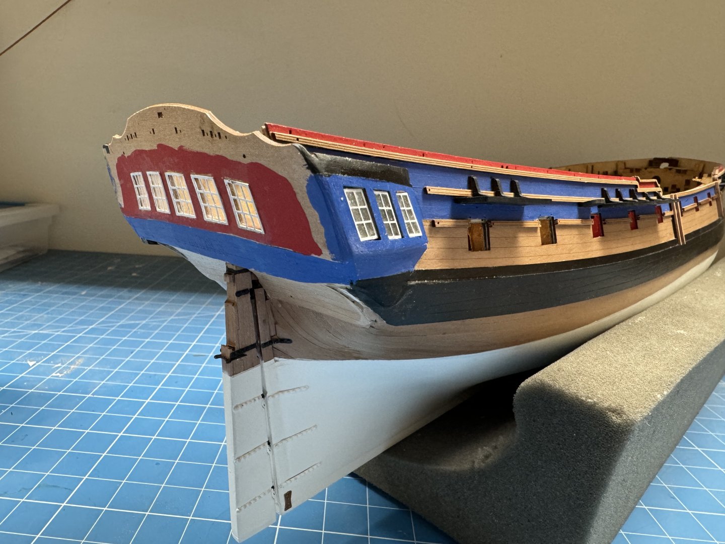
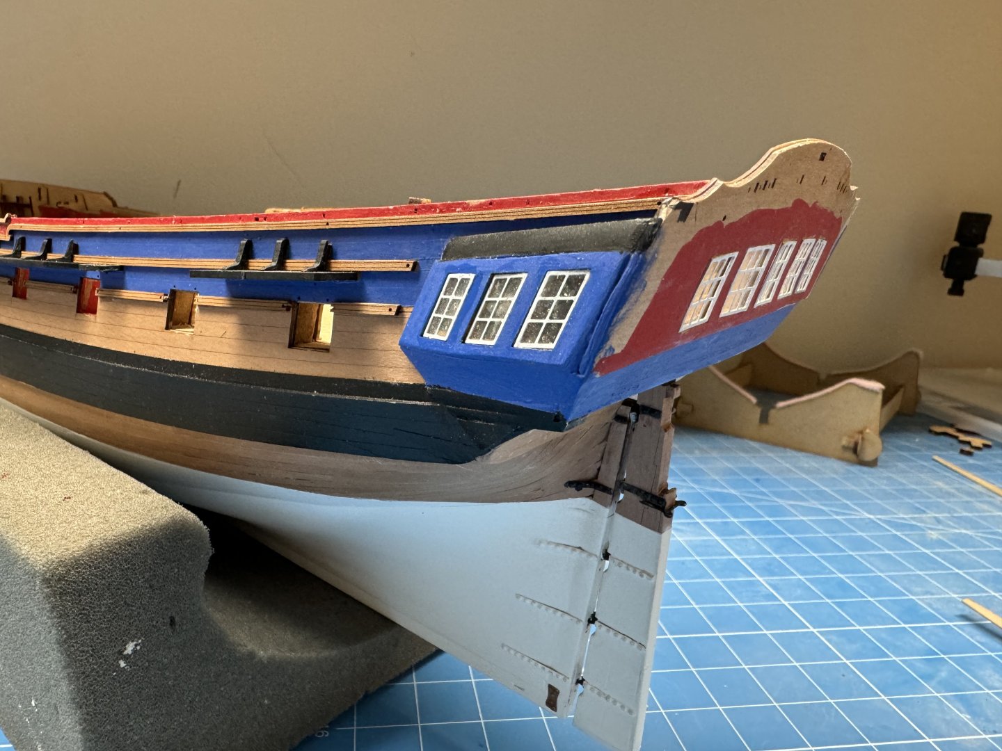
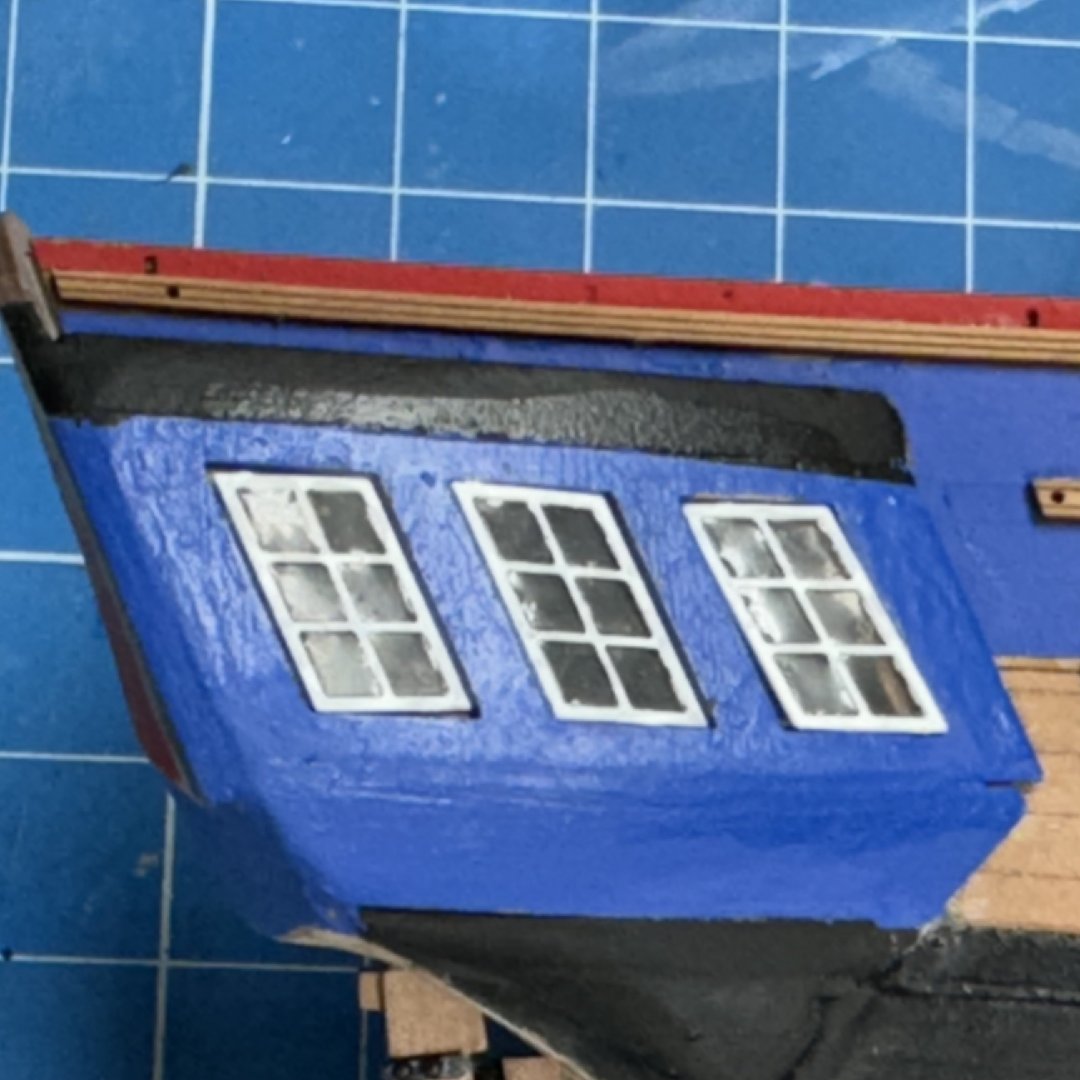
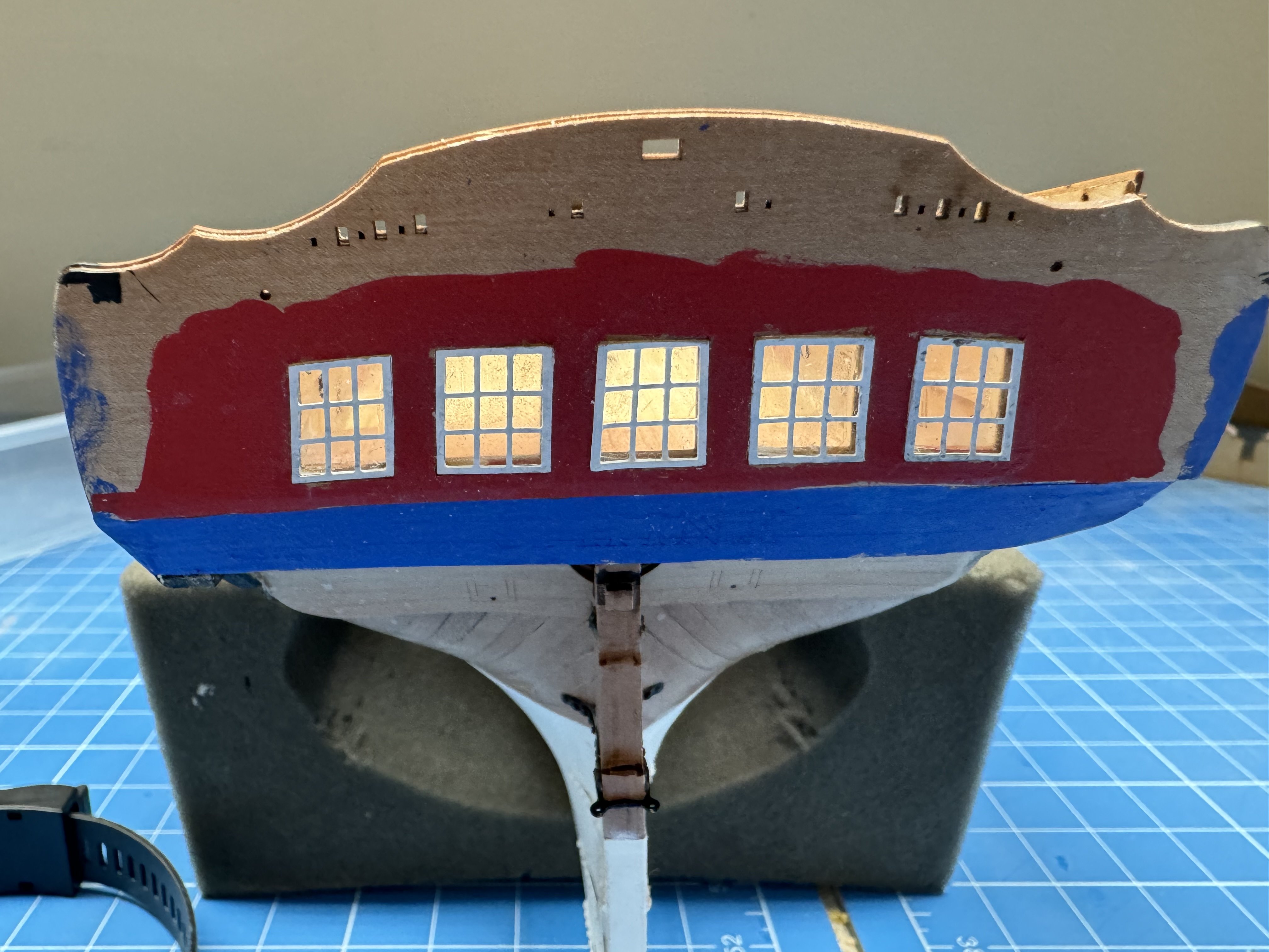
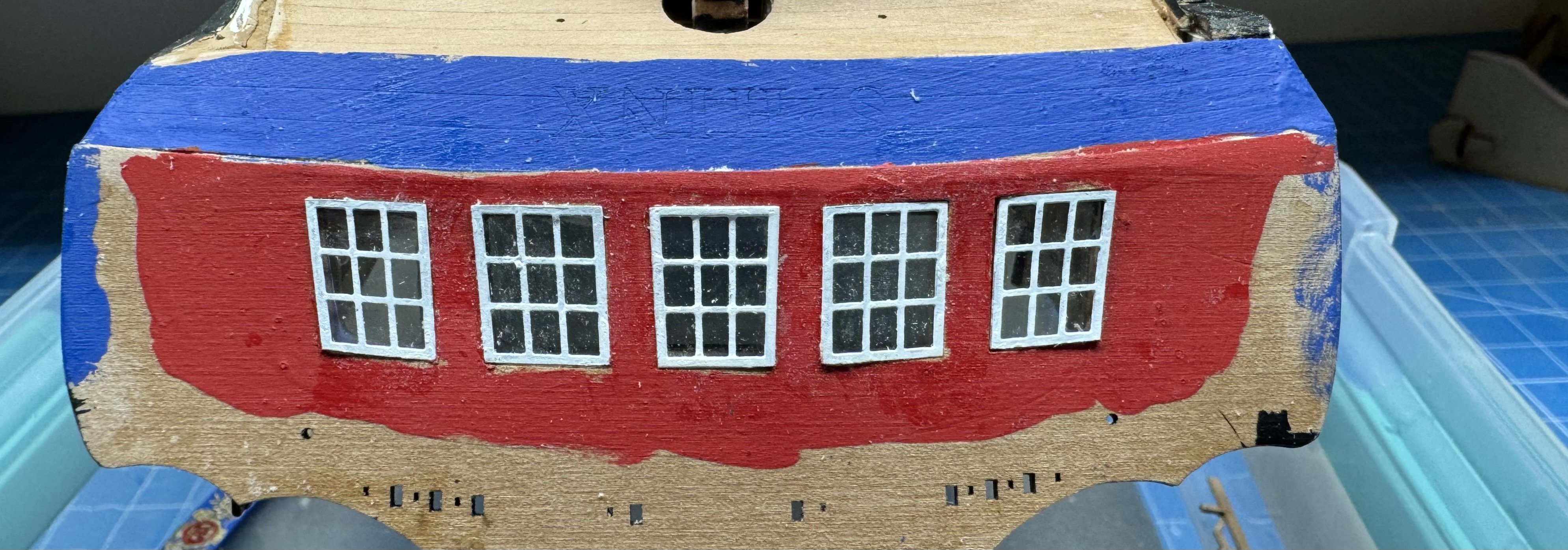
 Windows are done and yes you can see something through the stern windows. Have to leave a few planks off the q-deck to have and hope of enough light to actually SEE something. Or find a way to rig little LEDs inside the great cabin. I have seen it done at 1/48 scale which actually looked like brass lanterns. Might work at 1/64th, just not on this model or by me.
- 422 replies
-
- 5
-

-
- Vanguard Models
- Sphinx
- (and 1 more)
-
Stern windows using acetate. Will have to get hull upright to see if the acetate makes a difference but I am committed now. Decided to use nitryl gloves while handling the acetate although I doubt fingerprints would be all that noticeable.

- 422 replies
-
- 6
-
-
- Vanguard Models
- Sphinx
- (and 1 more)
-
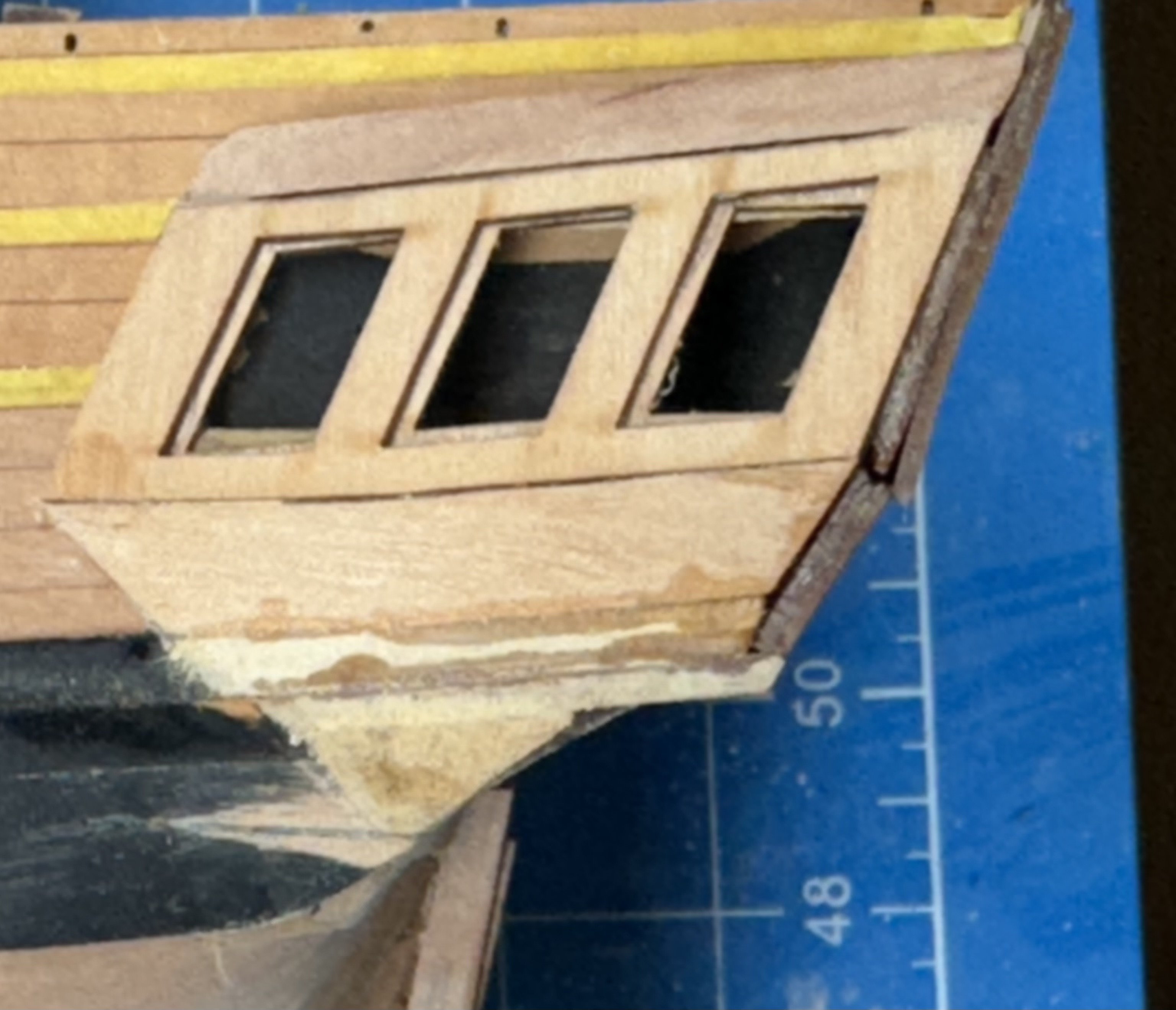
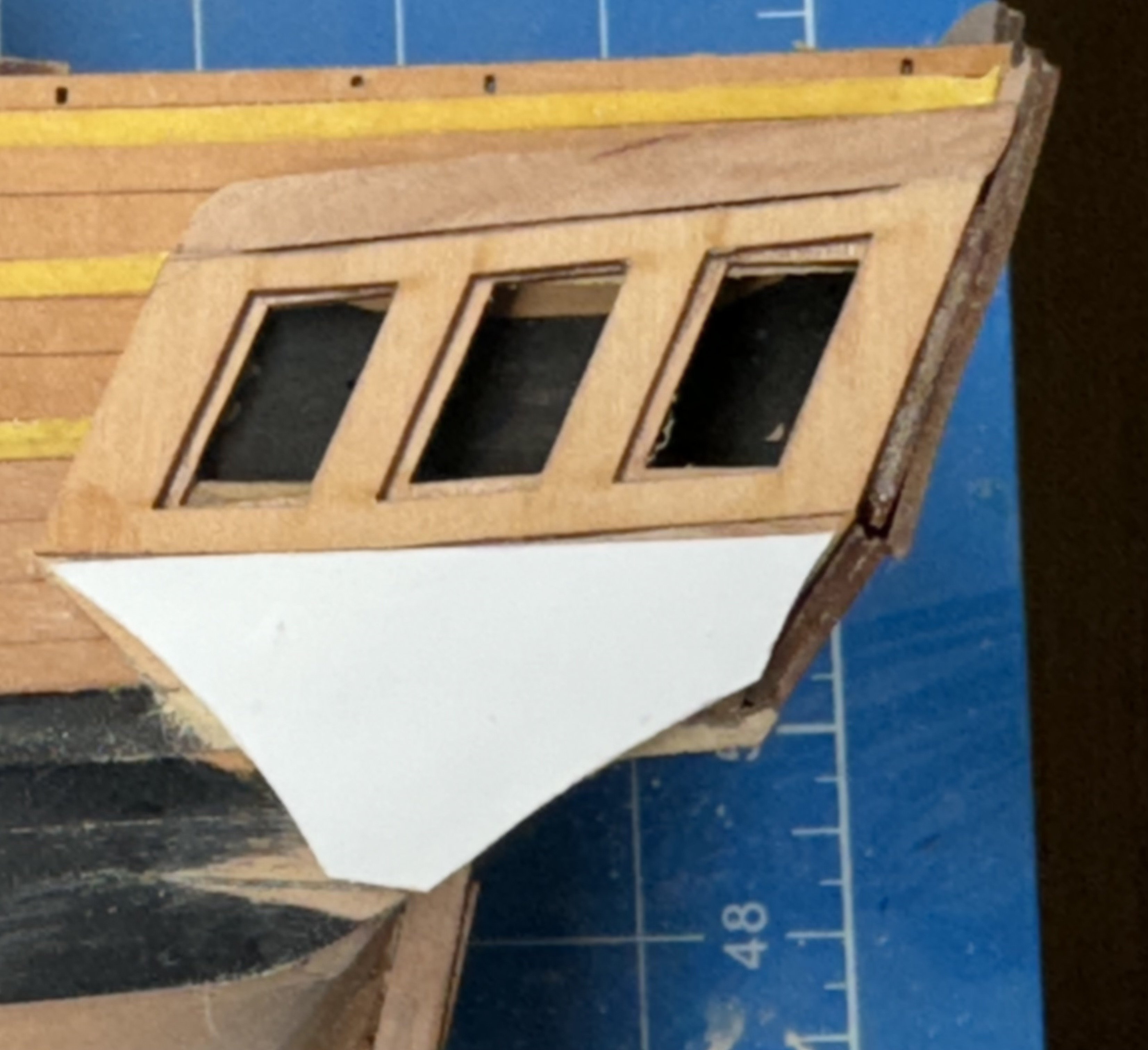
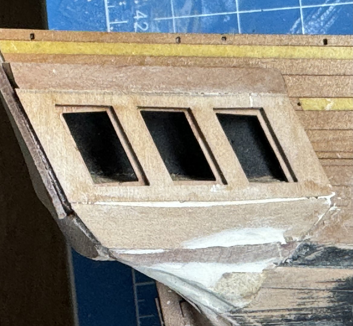
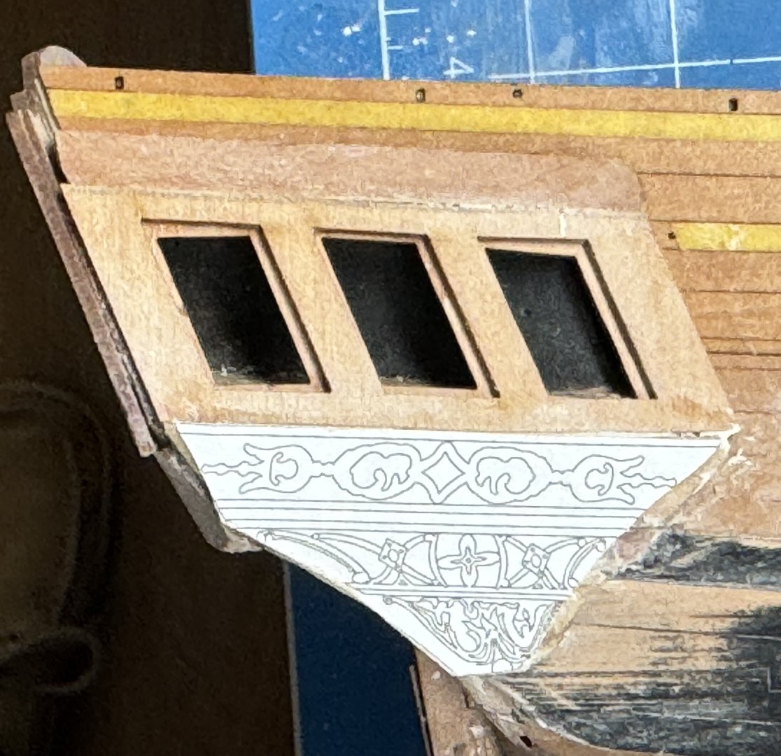
Starboard side q-gallery windows with "window maker" windows in place. I am thinking about doing the stern windows with the acetate since there is something to actually see (or will be someday) in there. Hopefully the decorations and trim pieces will cover some of the surface imperfections which are SOOO obvious in the pictures.
- 422 replies
-
- 6
-
-
- Vanguard Models
- Sphinx
- (and 1 more)
-
Bow details completed and first round of touch-up paint completed. Now on to the windows in the stern. My usual tactic for the windows is to use one of the "window making" products (the two I have are from Model Masters and Microscale. I have used both and have had reasonable success with them. The result (or at least my results) is NOT a perfect;y c;ear window as you will get with the acetate provided in the kit. For me it comes down to is looking through the window(s) important to your model - as it is for brunnels who has gone to considerable effort to make the interior much better than just the kit provides. Since I have two sets of window frames I am going to try at least the q-gallery windows with the window maker as there is nothing to "see" inside my q-galleries. More later.
- 422 replies
-
- 6
-
-
- Vanguard Models
- Sphinx
- (and 1 more)
-
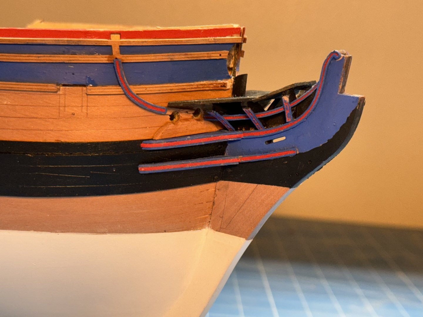
Port side bow details completed (at least for now). I took a detour up the instruction manual and got the figurehead out of the fittings box and tried to fit her (pretty obviously a female) on the stem. No luck - I had to widen the slot in the figure (and clean out some mold left-overs) and narrow the stem. Glad I looked now as following the instructions it would have been considerably more difficult to narrow the stem as the figurehead is the last step (masts and rigging excluded) before the stern lanterns. Would have potentially created considerable rework which is "no problem" now.
- 422 replies
-
- 3
-
-
- Vanguard Models
- Sphinx
- (and 1 more)
-
Thanks Hamilton - steady hands are certainly helpful. At my advanced age it is something to be cherished as it does not last "forever". Yes brunnels I used the Vallejo Liquid gold. The bottle has a ball bearing (for lack of a better description) in it to help mix things up but I had to be careful to dip the brush where the gold was not the carrier as they separate almost immediately. Sometimes I had to go back and hit an area a second time. I did not add any alcohol as was noted in the instructions as I painted the blue first and did not want the gold "flowing" places I did not want it to go. I better go work on the figure head while I am "hot" so to speak.
-
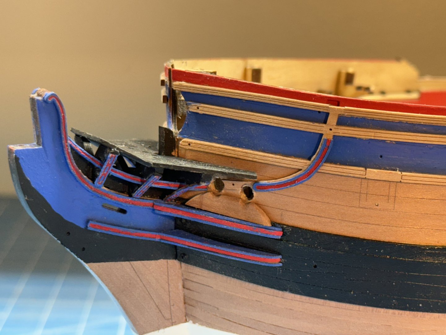
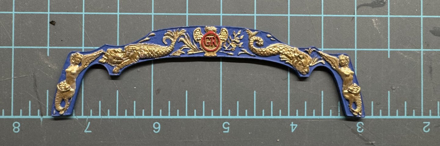
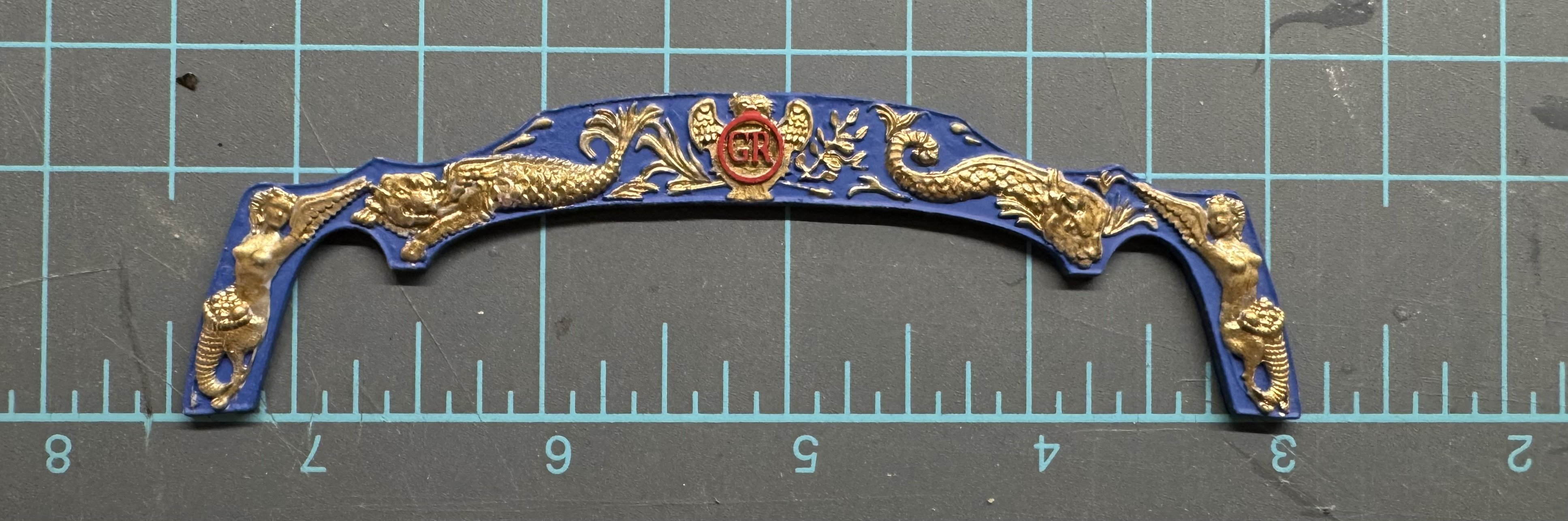
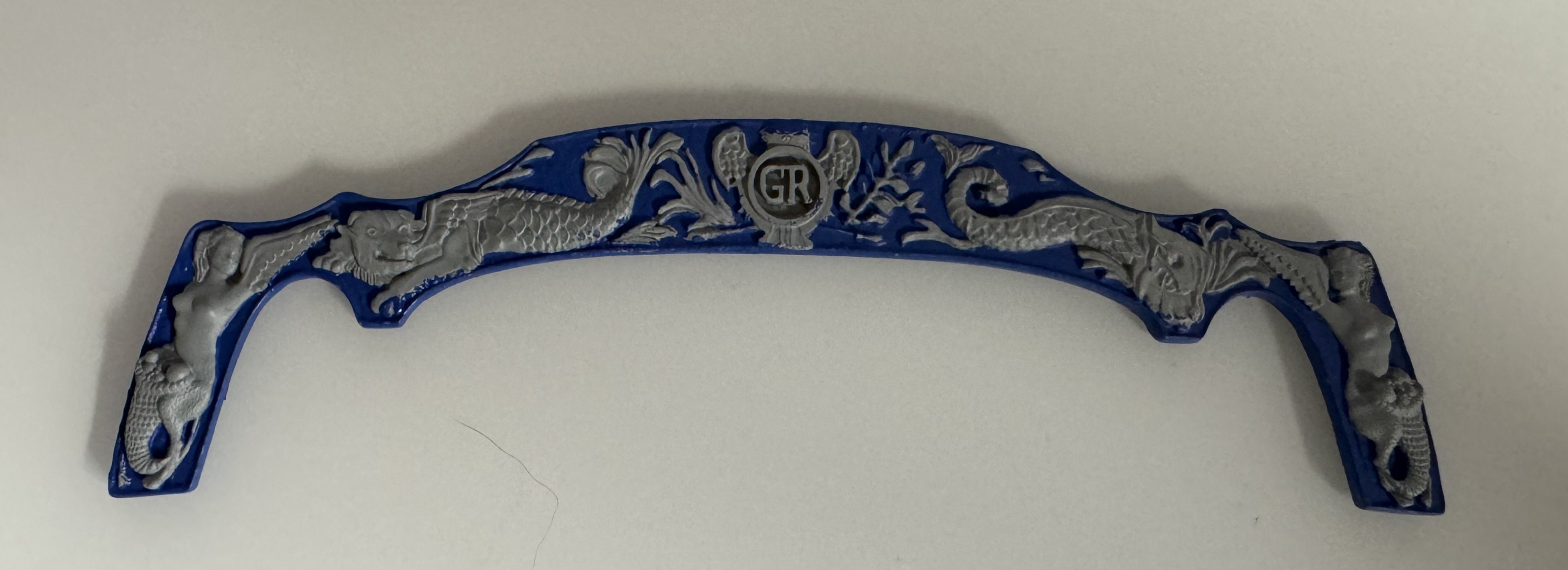
Thanks guys😀 While messing around with painting all the detail on the head rails, etc. I also manged to get the stern decoration painted. I combined the prototype and brunnels schemes adding the red in the center to the blue and gold of the prototype. There are probably a few areas that need one more round of touch-up but that will have to wait until I am sure the gold is dry and the head details are done.
- 422 replies
-
- 10
-
-
- Vanguard Models
- Sphinx
- (and 1 more)
-
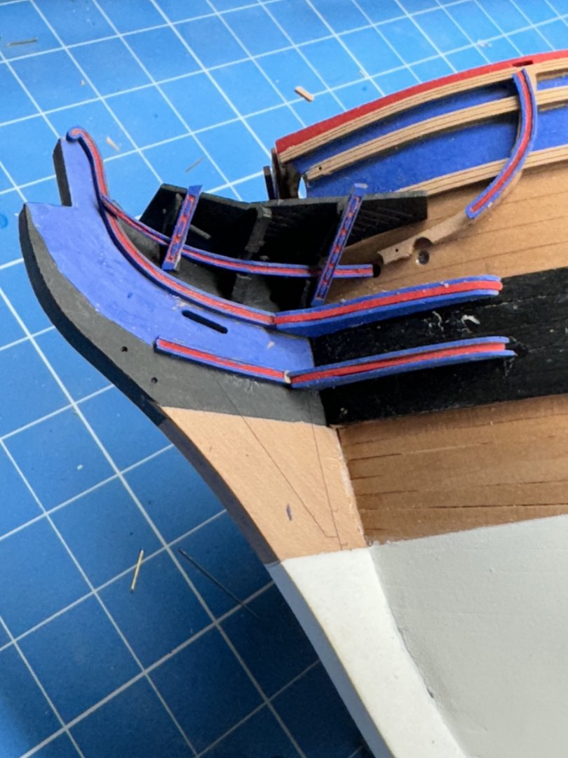
So once I got to the point above I realized that if I did one set of "trim" in the red/blue motif I had to do the rest as well. So here in dry fit (less one piece I forgot to paint) are the other "trim " pieces for the port side painted in the same fashion. I think painting these is good practice for the molded piece across the stern
- 422 replies
-
- 8
-
-
- Vanguard Models
- Sphinx
- (and 1 more)
-
Very nice job, shame to paint it white.
-
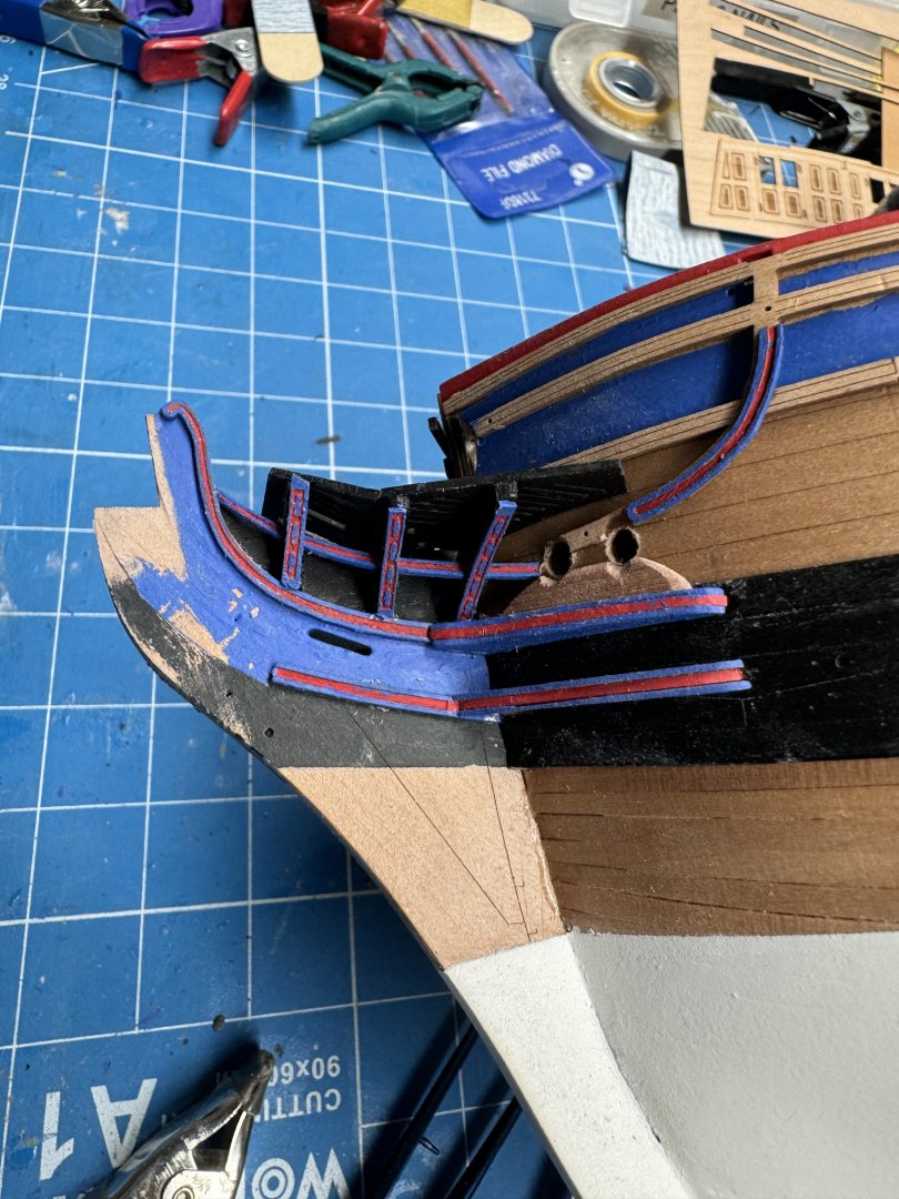
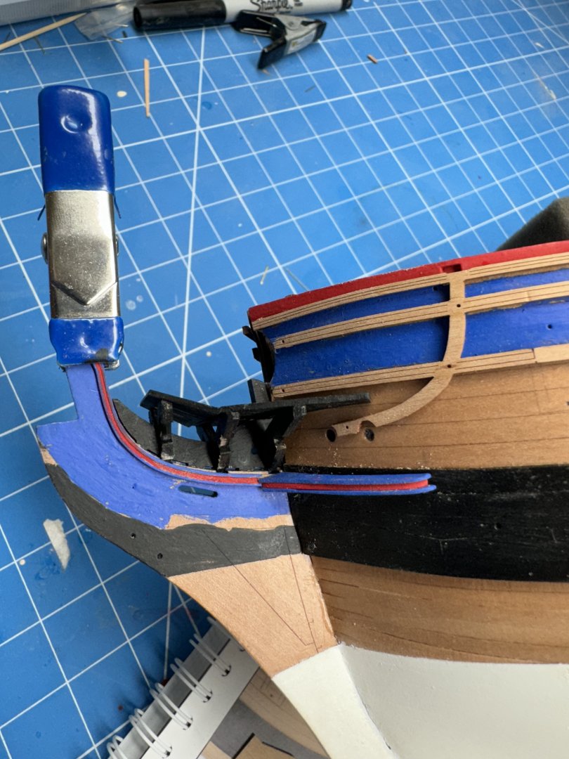
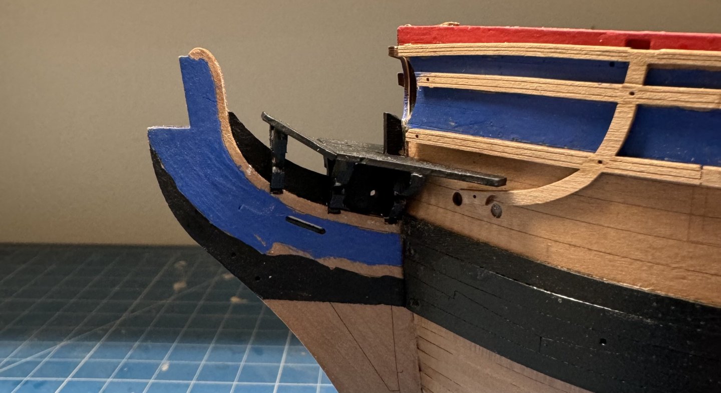
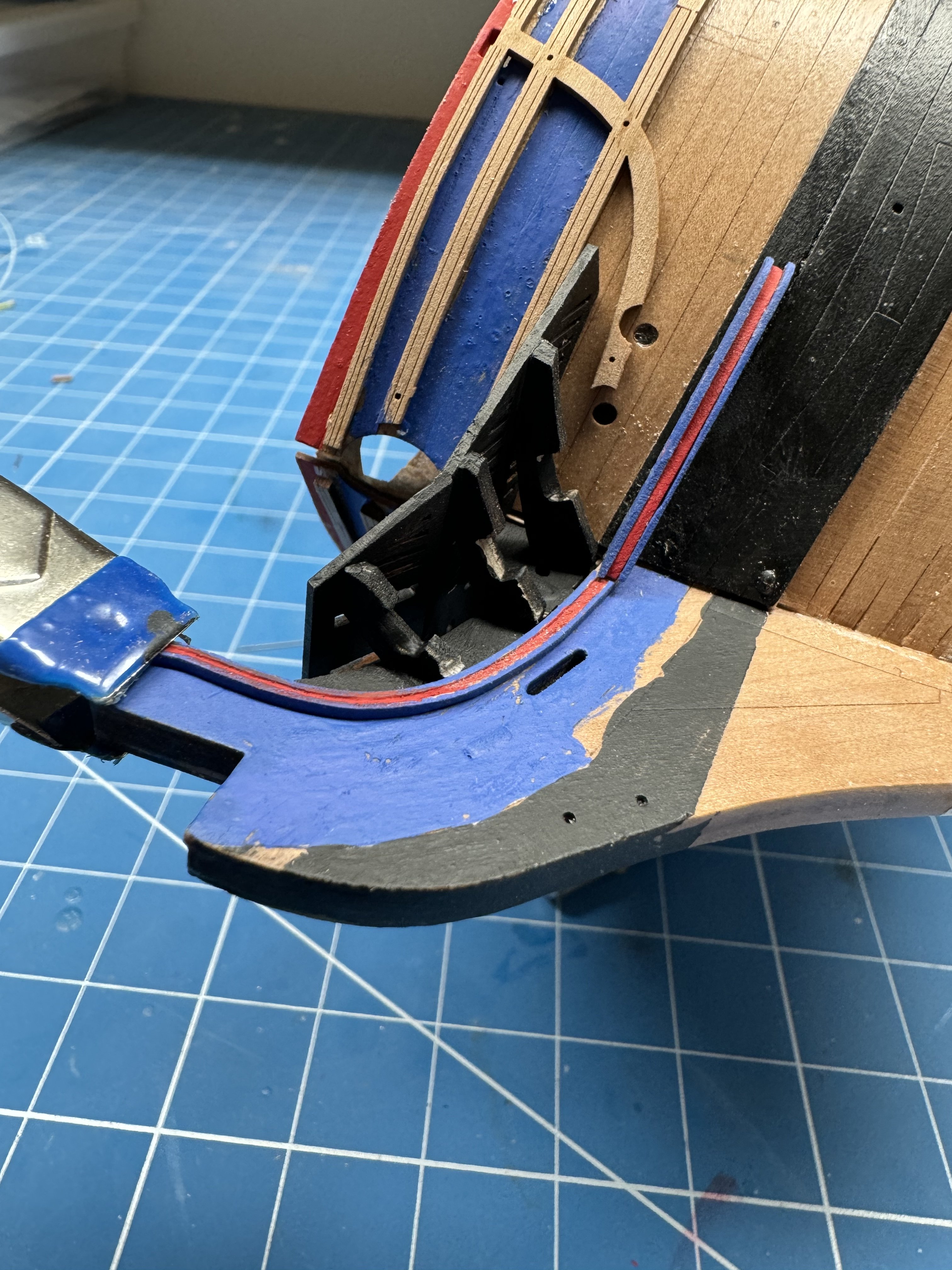
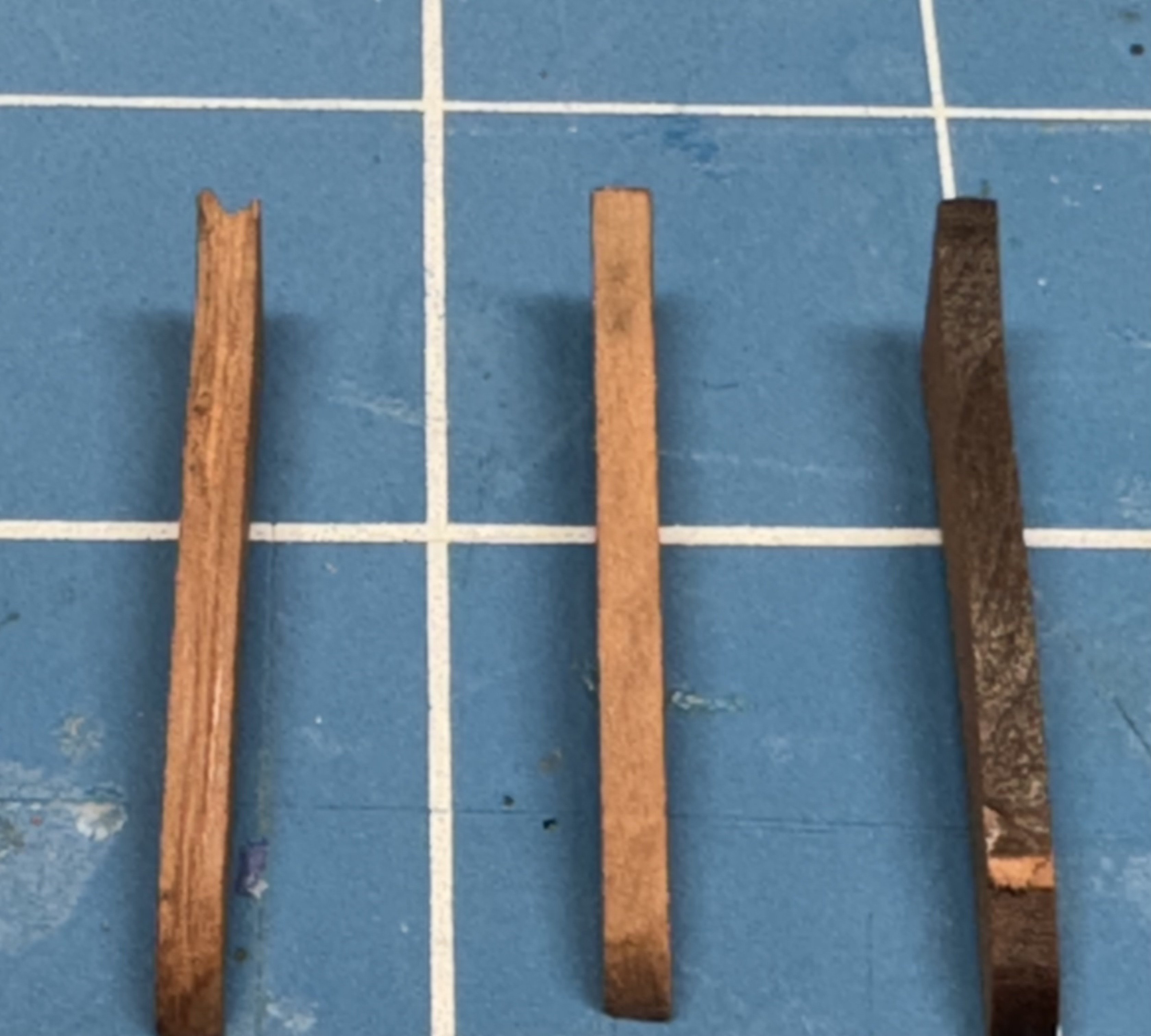
So here is my attempt at the hair bracket and the upper cheek dry fit for now (hence the clamp). I abandoned my blue/ocher paint scheme in favor of continuing the blue/red theme used throughout the model. No sense (IMHO) in introducing another color now.. I made the cheek from three layers, two of 0.6mm pear (excess from a carrier sheet) and one layer of 1mm pear also salvaged from a carrier sheet. The baseline cheek was 2.17mm thick so this should be very close. I can't say I am looking forward to making nine more "cheek blanks" but I think this looks good enough to proceed and I am not sacrificing any of the kit pieces in case madness over takes me and I decide to revert to the kit implementation

- 422 replies
-
- 7
-
-
- Vanguard Models
- Sphinx
- (and 1 more)
-
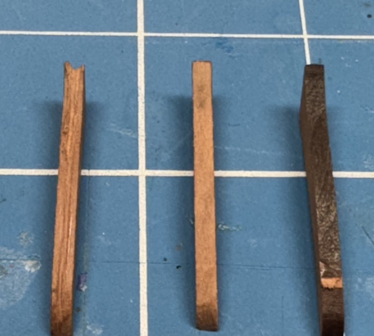
Assembly of the grating and support arms was pretty uneventful. Just followed the instruction. I painted the stem as seen below. The black continuing from the wales and then up the stem and the blue between the hair brackets. For the cheeks I wanted something that would continue the hair bracket "decoration". On the prototype since the cheeks are mounted on the wales they were just painted black. I want something a bit more elegant but will fall back if that proves to be more than that of which I am capable. Below is my first attempt at getting a grove down the center (more or less) of the cheek. I want to paint the inner section blue with ochre (or maybe gold) on the edges. I plan to paint the hair bracket to match. I am toying with the idea of recreating the cheeks in three pieces so I would have a more consistent "edge" but my power tools are all "incapacitated" awaiting the coating of the garage floor on Wednesday. Might be more challenge than I am "up" for at the moment but something I will have to think about some more.
- 422 replies
-
- 3
-
-
- Vanguard Models
- Sphinx
- (and 1 more)
-
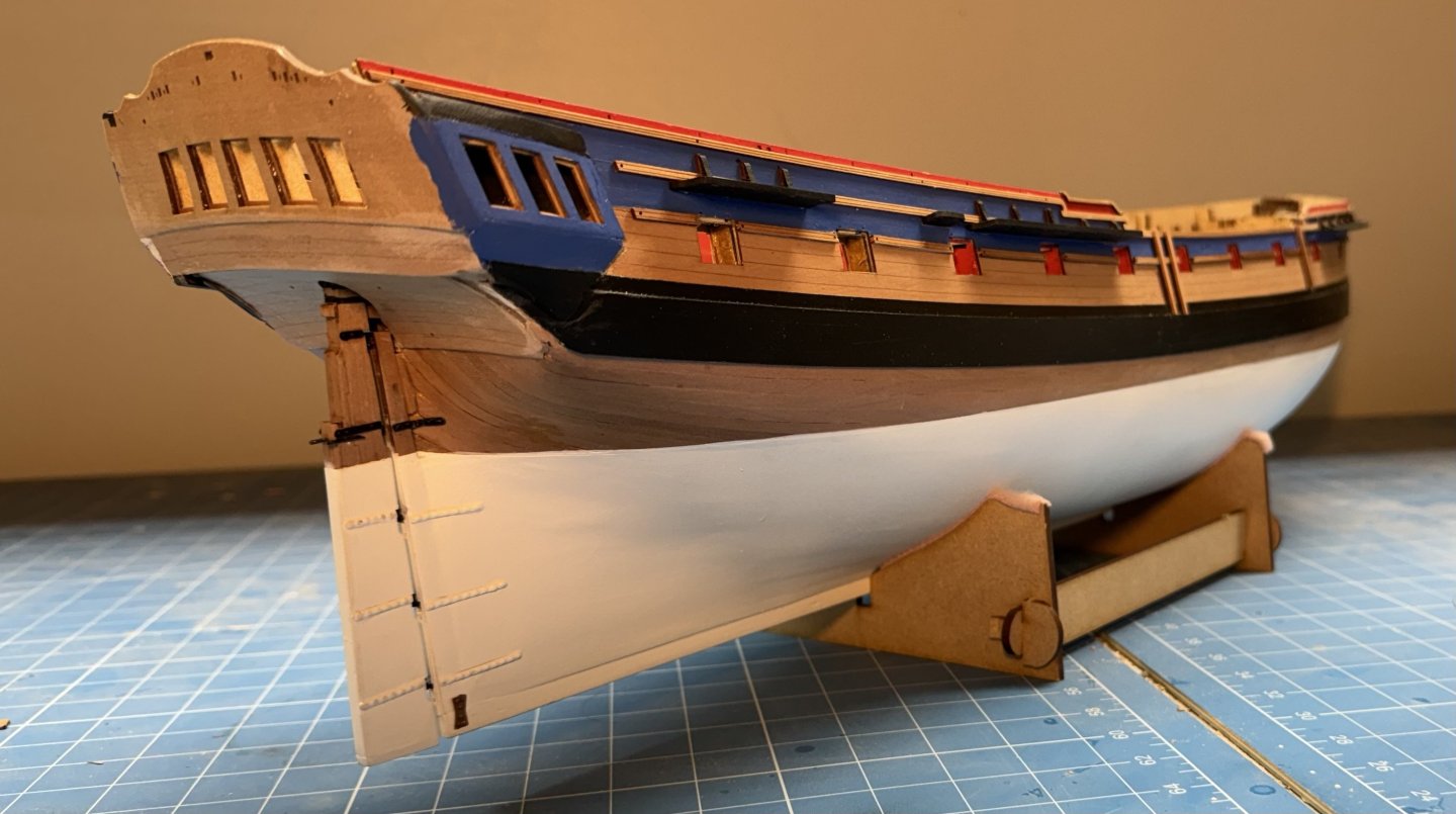
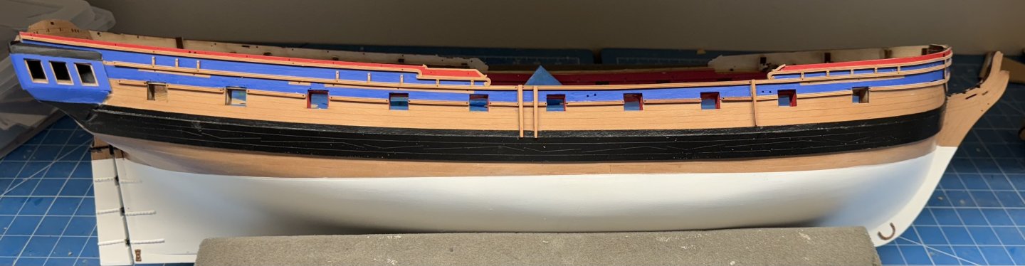
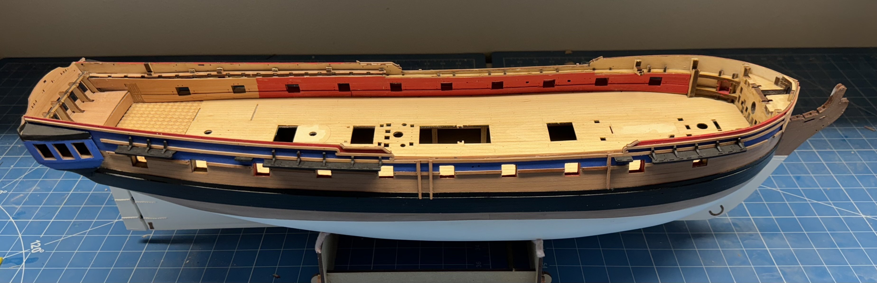
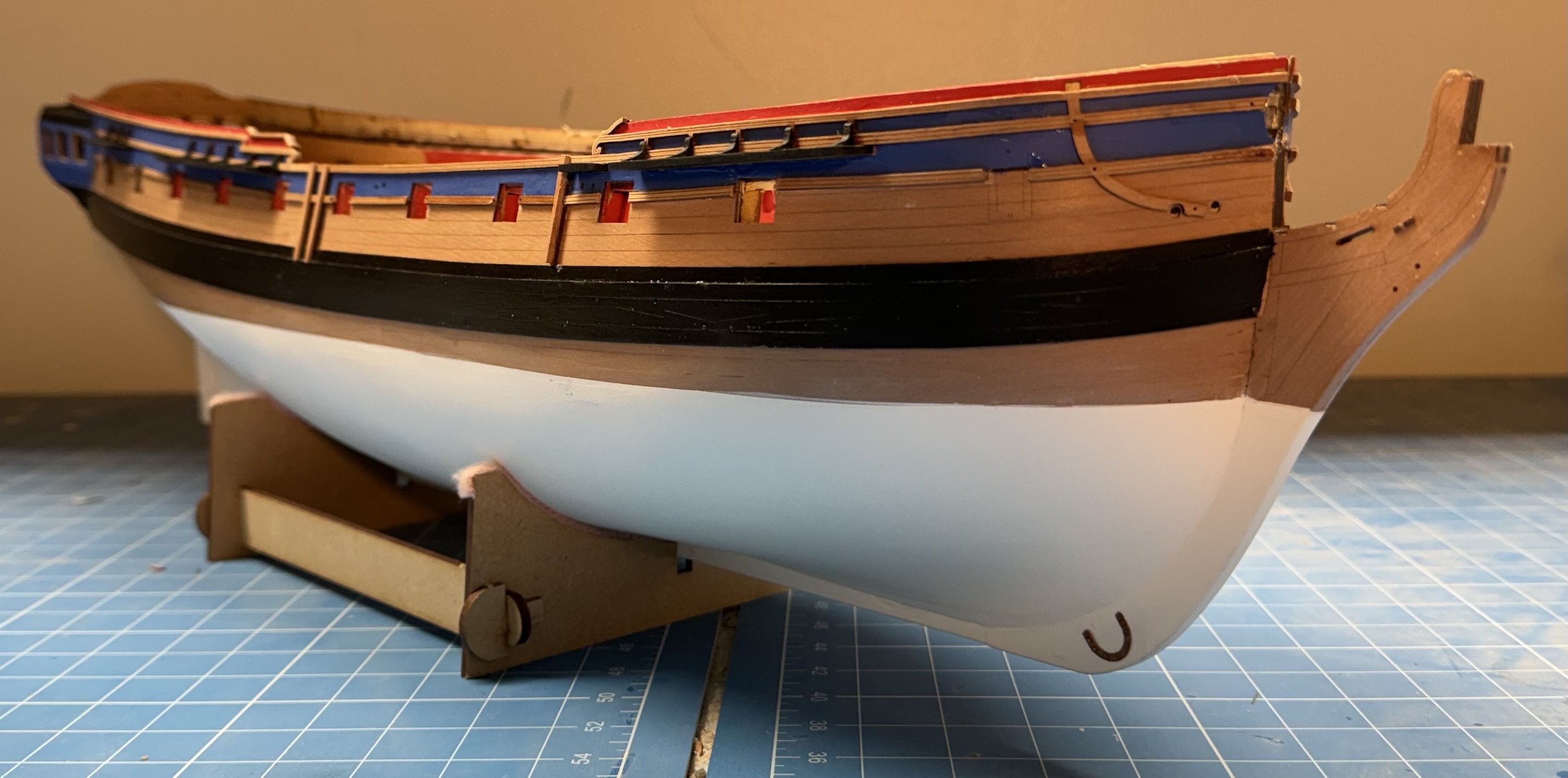
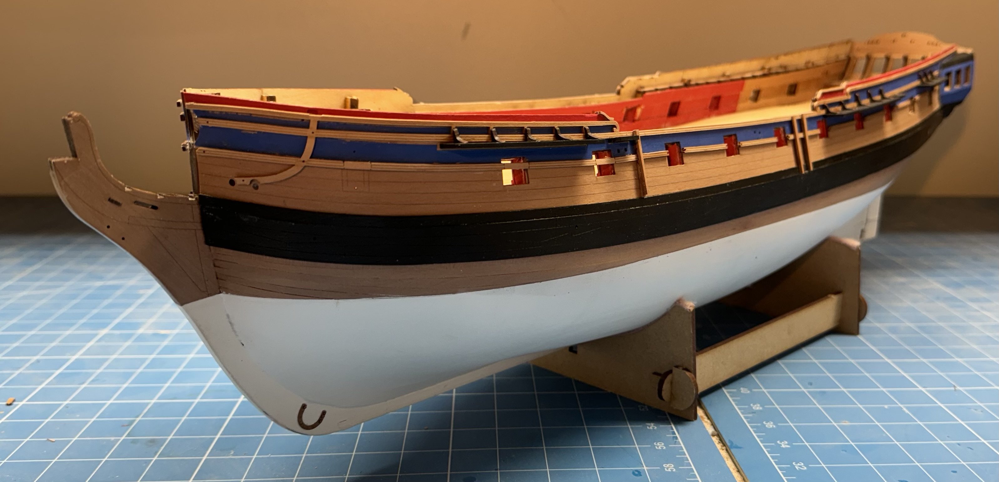
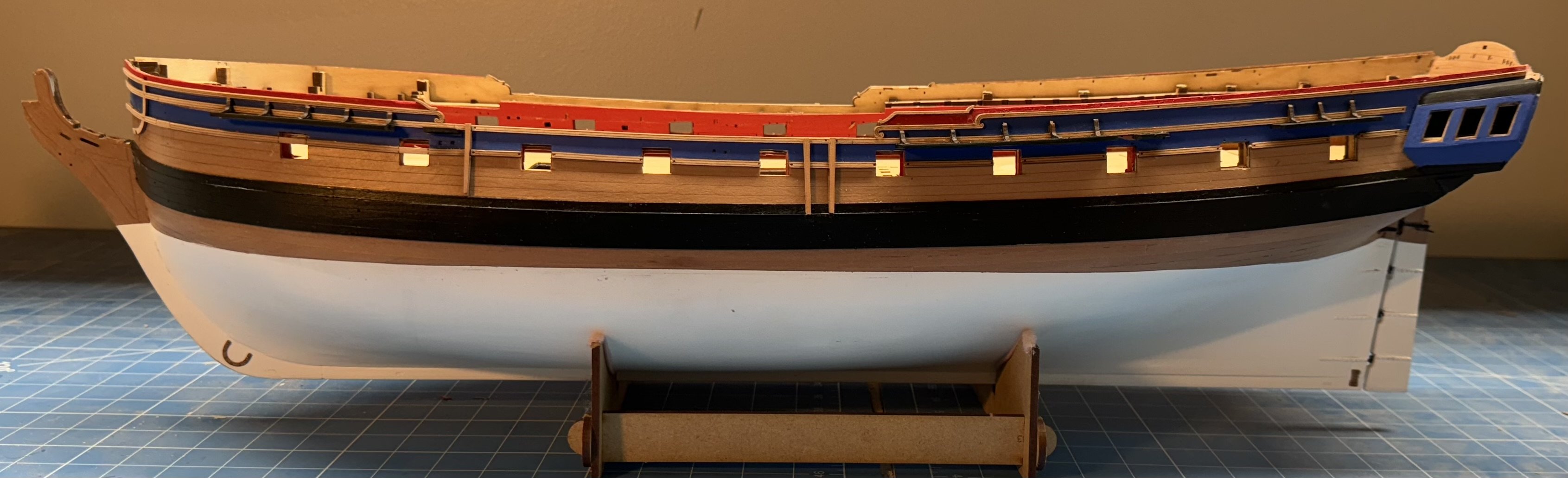
Channels and knees completed on both sides. Time for a little touch-up painting and since I already "did" the rudder I should be at step 275 in the instructions ready to start work on the bow. I am still thinking about how I want the paint scheme at the bow to look so I will have to decide something pretty quickly or be faced with trying to execute whatever I decide with the "bow clutter" in the way. In any event here is what my Sphinx looks like at step 275.


- 422 replies
-
- 10
-
-
- Vanguard Models
- Sphinx
- (and 1 more)
-
Thanks guys - I bit the bullet and used the gray primer I had. I thought any spray was better than me trying to brush a primer on. Looks like it worked fine. I have the Vallejo blue background pretty well completed and need some 000 brushes to add the gold as I am sticking with the kit color scheme..

-
I am about to start painting the stern decoration piece and wondered if you used a primer before painting with the blue? I have some spray gray "self etching" primer that I was going to use but hesitate since there is no substitute if the primer were to "attack" the resin. I have some other primers designed (so I am told) for use on Britannia metal (or whatever they make them out of these days) figures but I am not sure that would be satisfactory either. Any info you can provide would be greatly appreciated.
-
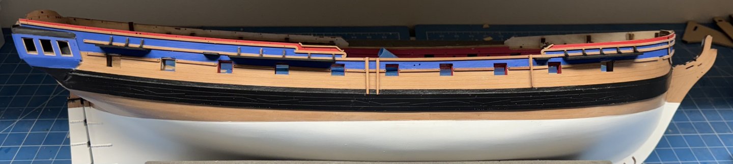
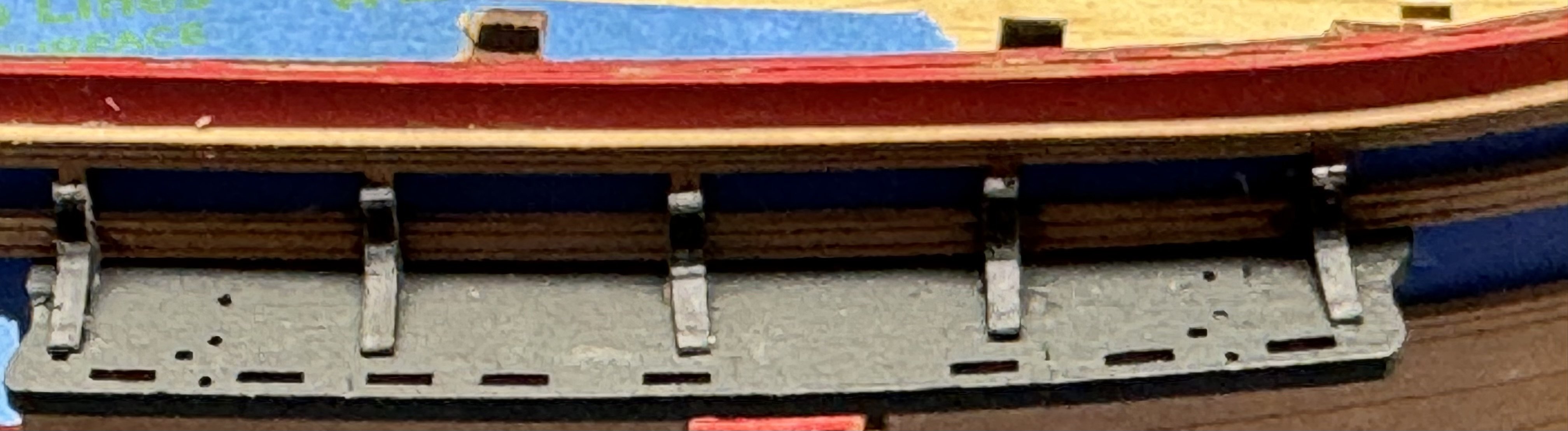
I finished the molding on the port side and now it is on to the channels. Given that the channels are going to take all the standing rigging and most of the running rigging "load" it is imperative that they be securely anchored to the hull. Don't ask me how I know but having to "re-secure" a channel (or pin rail) during the rigging process is to be avoided if at all possible. The addition of the pins securing the channels to the hull is a good start and hats off to Vanguard for supplying them as part of the kit. I used medium CA on the edge of the channel and when that was dry added a bead of medium CA along the underside of the channel (hull turned upside down) as an extra measure of "security". Then to make sure the molding (which is going to support the knees) as securely fixed to the hull I added .020 phosphor bronze pins through the holes already in the molding at the locations behind the channels. I also scraped the black paint off the channel where the knees are going to be placed. I decided to paint the knees black rather than leave them "natural" - probably to avoid cleaning off the laser char on very small curved surfaces. Anyway I painted the sides while they were on the carrier sheet as I do not trust my hand to paint the sides once in place. Although the area behind the channels is not going to be all that visible after all the deadeyes and rigging are in place. So here is a closeup of the fore channel and an overall view of the starboard side with all the channels and knees in place.

- 422 replies
-
- 11
-
-
- Vanguard Models
- Sphinx
- (and 1 more)
-
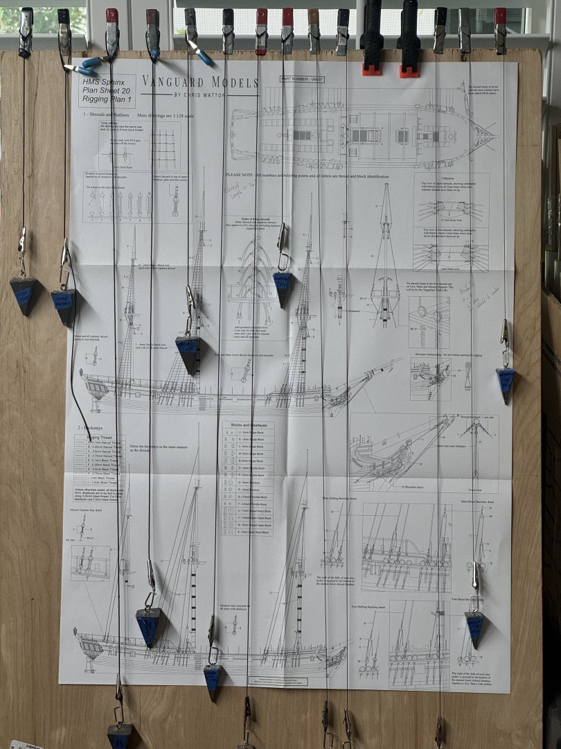
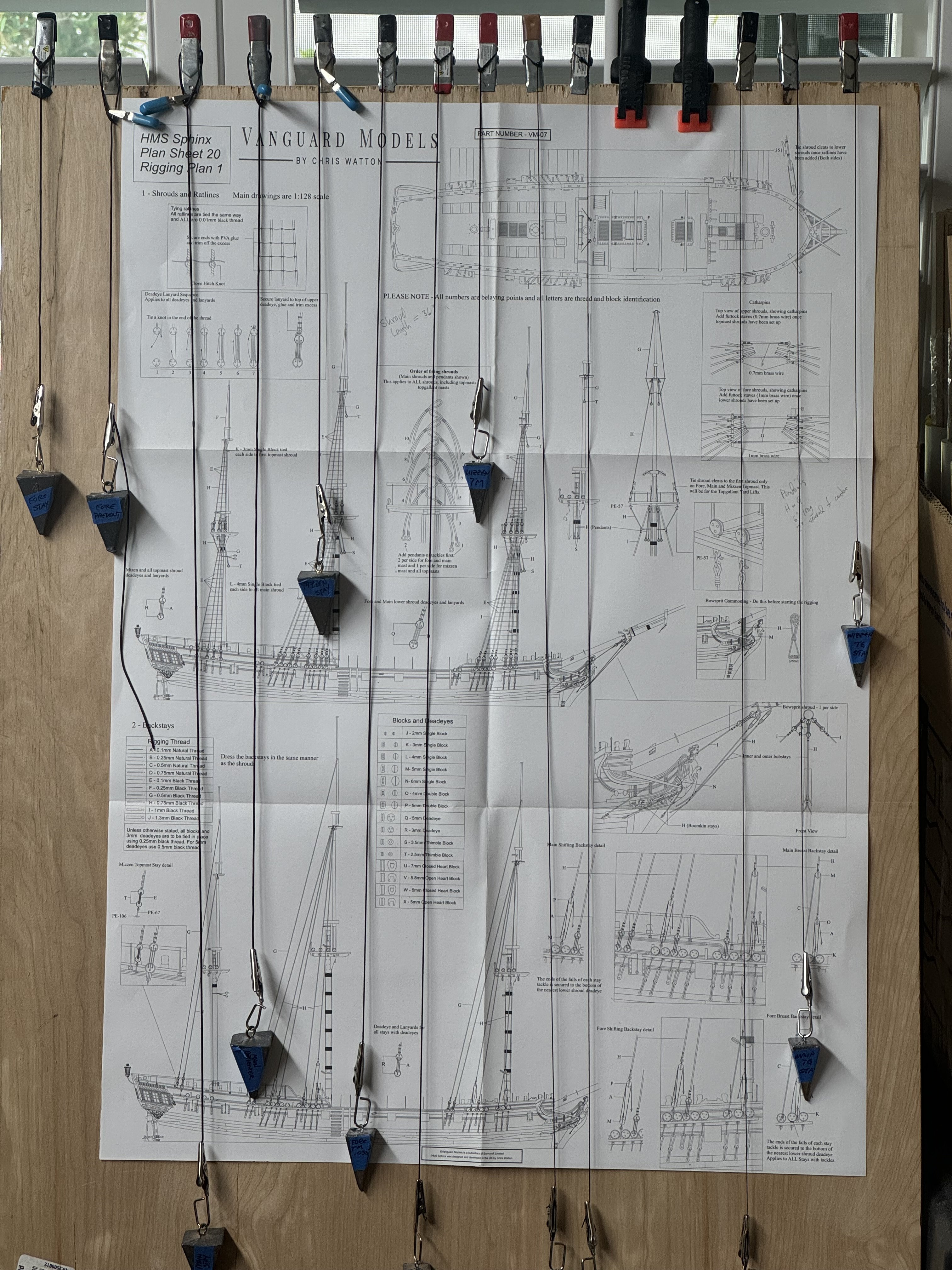
While waiting for things to dry; or for a break from working on the hull I have been working on the standing rigging. According to various sources the lower stays (Main and Fore in particular) were parcelled and served to reduce damage from chafing by the lowers sails (courses and jibs mostly) and running rigging. I followed this practice, well just the serving. I have three serving machines, the Syren "Serv-o-Matic" and two versions (including the latest) from Domanoff's Workshop both of which are powered. I did almost all the work on the Serv-o-Matic or the latest Domanoff in manual mode. I was not able to get the powered option to work smoothly - there is enough resistance in the gear train that the power to overcome that makes things too fast (for me) to handle without needing a third (and sometimes fourth) hand to keep things moving as they should. Backing off the power once things get moving did not work for me as I was unable to reduce just enough to keep thing moving, it always stalled. And for what I am doing - the longest served item required is about 25" (main stay or preventer I can't remember which is which) which is four "passes" on the Serv-o-Matic. Used at at full length the Domanoff can do 12" in one "pass". Don't ask me how I know but for long serves you have to be serving against the lay of the line. Otherwise by the time you are 9 - 10 inches along you have untwisted the line you are serving and things get "interesting". So the first five stays (on left) below are the Fore stay, Fore Preventer stay, Main stay, Main Preventer stay and Mizzen stay. Then the five Top Mast stays and finally the three Top Gallant stays. They are normally hanging behind my plans easel but I brought them to this side for the picture. I have a few more shrouds to finish when things get slow on the hull but it is good to get these "out of the way". I only wish there was some way to do the ratlines ahead. I have seen the commercial templates but cannot understand how I would be able to use them. Seems like too much critical measurements required and no way to check until everything is done. I'll just have to slug along when the time comes.
- 422 replies
-
- 8
-
-
- Vanguard Models
- Sphinx
- (and 1 more)
-
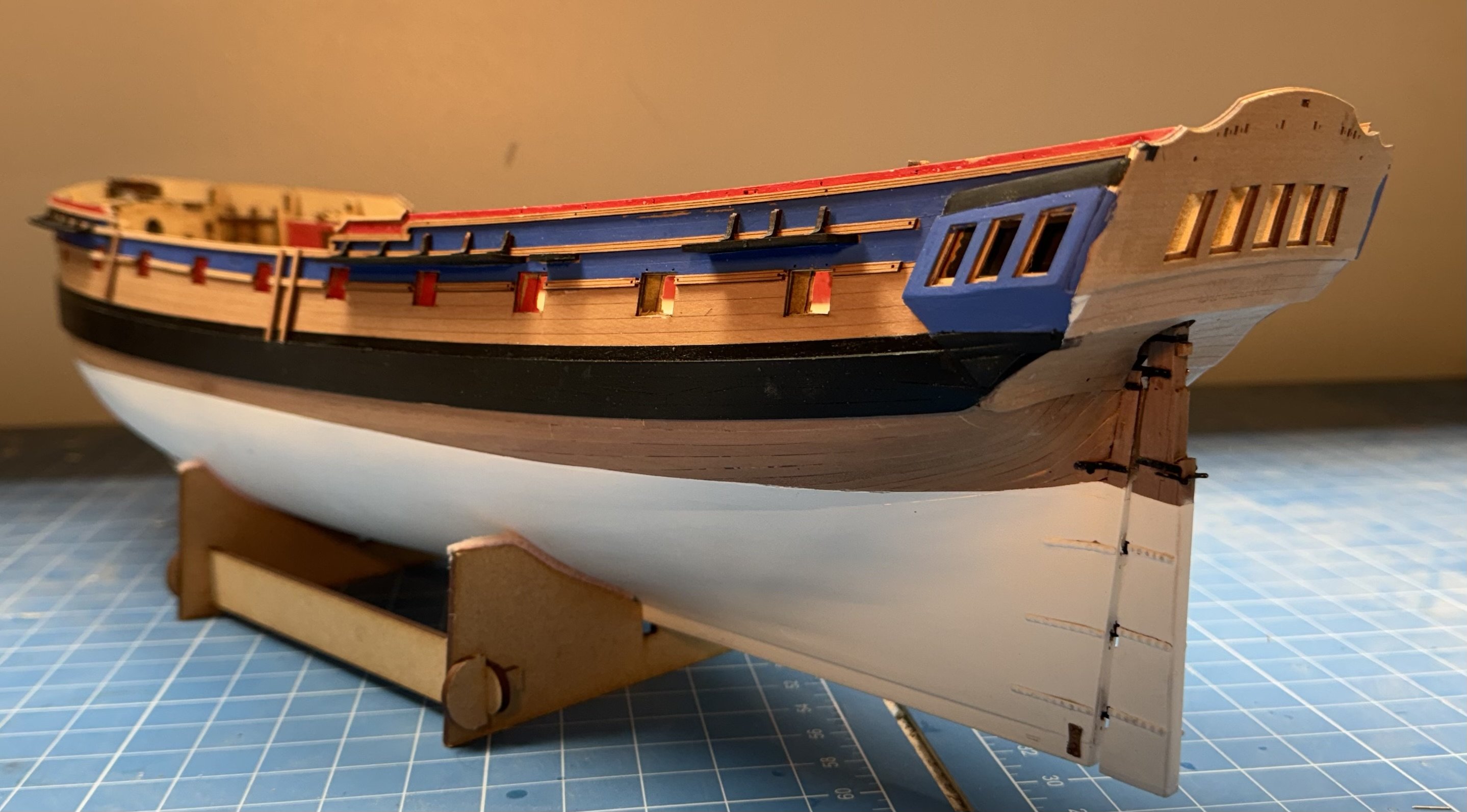
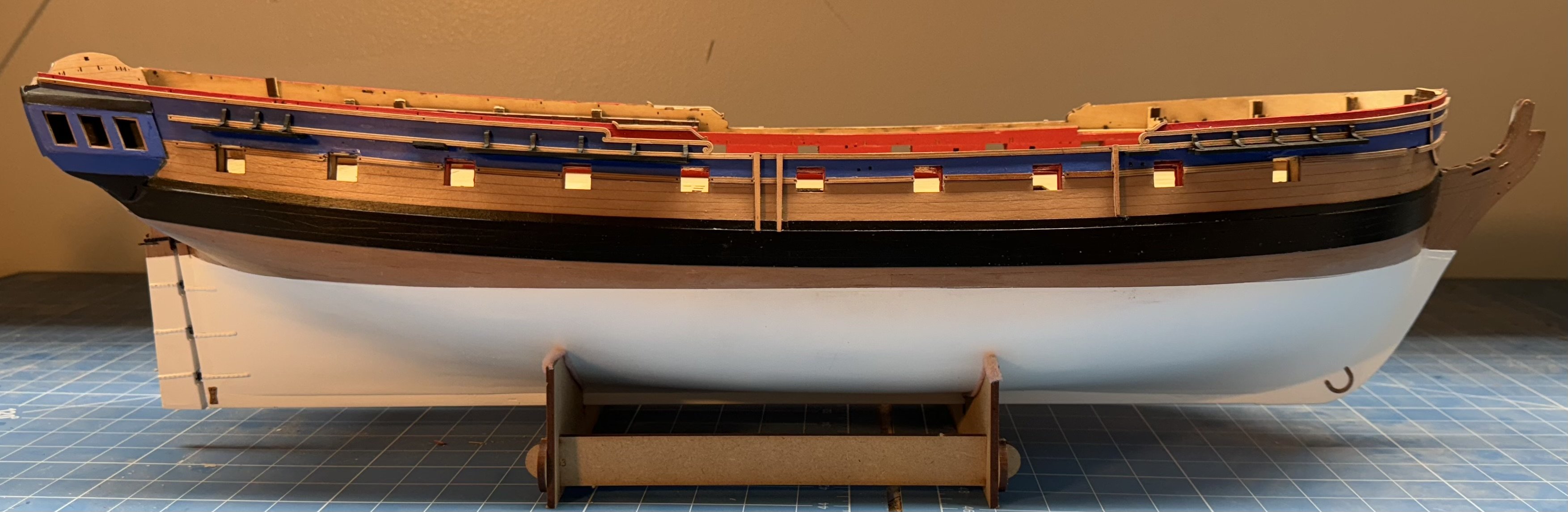
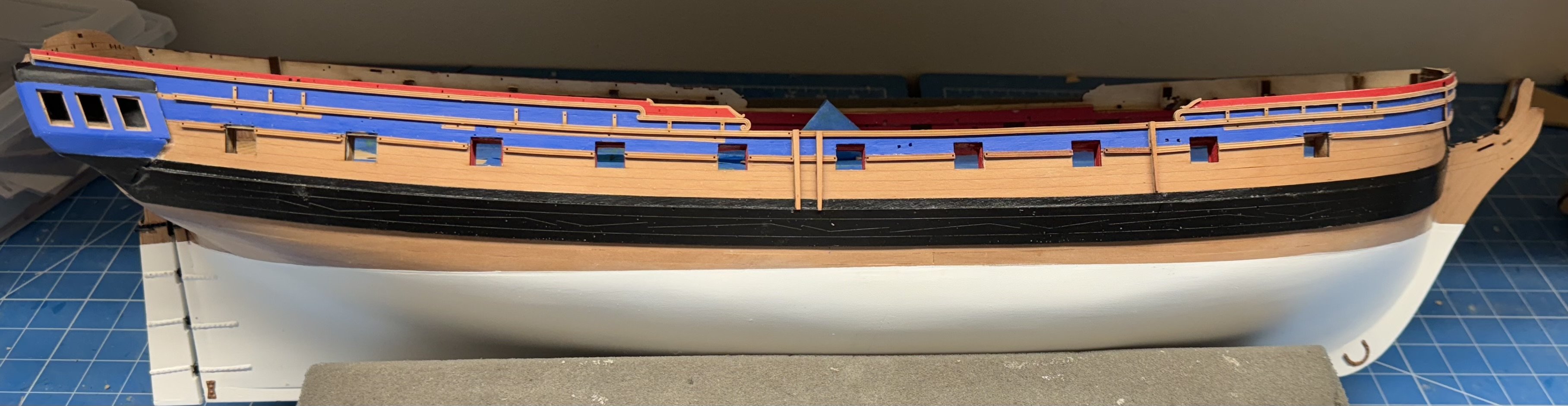
Starboard side painting and molding completed. At the q-galleries I decided to extend the blue band across the area under the windows (and eventually across the stern) in place of the black shown in the prototype. The jury is still out but I am considering painting the lower transom black to extend the black band of the wales all the way around the ship. I trying to figure out what to do at the stem. Instructions show black above the wales until at the stem where it turns blue. But I have a bit of time yet before I need to do anything "up there". On to the port side.
- 422 replies
-
- 7
-
-

-
- Vanguard Models
- Sphinx
- (and 1 more)
-
Thanks Thukydides. I probably should have at least taken a pass at the pin heads with the same 220 sanding stick I used to smooth out the back. Would have given the pin heads a "flattening" but probably not very noticeable under the paint. I first tried using the heads off plastic bolts used on scratch built model train engines but I did not have a size that worked and my experience trying to get the right size in a reasonable amount of time had me decide to go with the pin heads.
- 422 replies
-
- 1
-
-
- Vanguard Models
- Sphinx
- (and 1 more)
-
Rudder now installed and fish plate added. Rudder might be a hair too long now but not enough to make me want to try and shave a .1 or .2 mm off. Having determined that the water based Vallejo Flat White and the oil based Testors Flat White (the spray I used on the hull/rudder) are NOT the same I ordered a bottle of the Testors Flat White since the paint does not stick to the pin heads particularly well. I have two heads to touch up already. Back to painting the bulwarks.

- 422 replies
-
- 4
-
-
- Vanguard Models
- Sphinx
- (and 1 more)
-
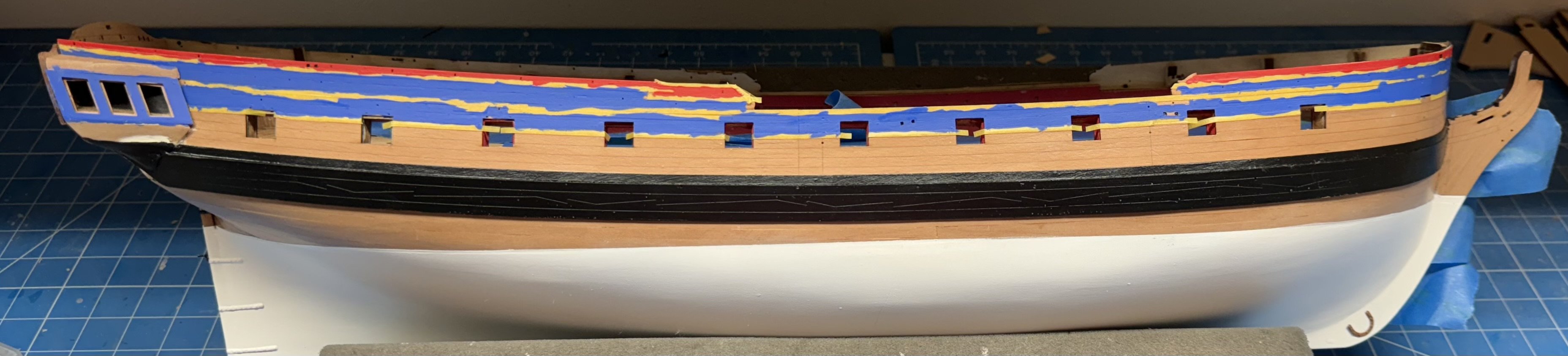
Rudder is in the paint booth so I started on the red and blue paint on the bulwarks. I had previously masked off the areas where molding and channels will go and put two coats of polycrylic flat to both give the paint something to adhere to and to seal the masked off areas. The masking tape is Tamiya 2mm which may be just a bit too wide but I could not find 1.5mm and have no intention of trying to make my own so we will just have to see how this works. Blue is Vallejo 70.962 Flat Blue and the red is Vallejo 70.957 Flat Red. Not very adventuresome but I am not trying for historical accuracy just something close to what looks as good as the paint in the instructions. Probably will take two to make sure I got all the "nooks and crannies".

- 422 replies
-
- 4
-
-
- Vanguard Models
- Sphinx
- (and 1 more)
-
I guess the "misaligned" rudder bothered me more than I thought yesterday because this morning I cut a piece off a 2mm carrier sheet and "scabbed" it onto the bottom of the rudder. Luckily I did not disassemble the paint booth yet so the rudder gets one more trip there. I also noticed that I did not add the "black bands" at the top of the rudder so one more thing to take care of before it is permanently installed. Given that most (maybe all) of the attachment is with the PE pieces it probably pays to not put any stress on the rudder through the rest of construction.
- 422 replies
-
- 5
-
-
- Vanguard Models
- Sphinx
- (and 1 more)
-
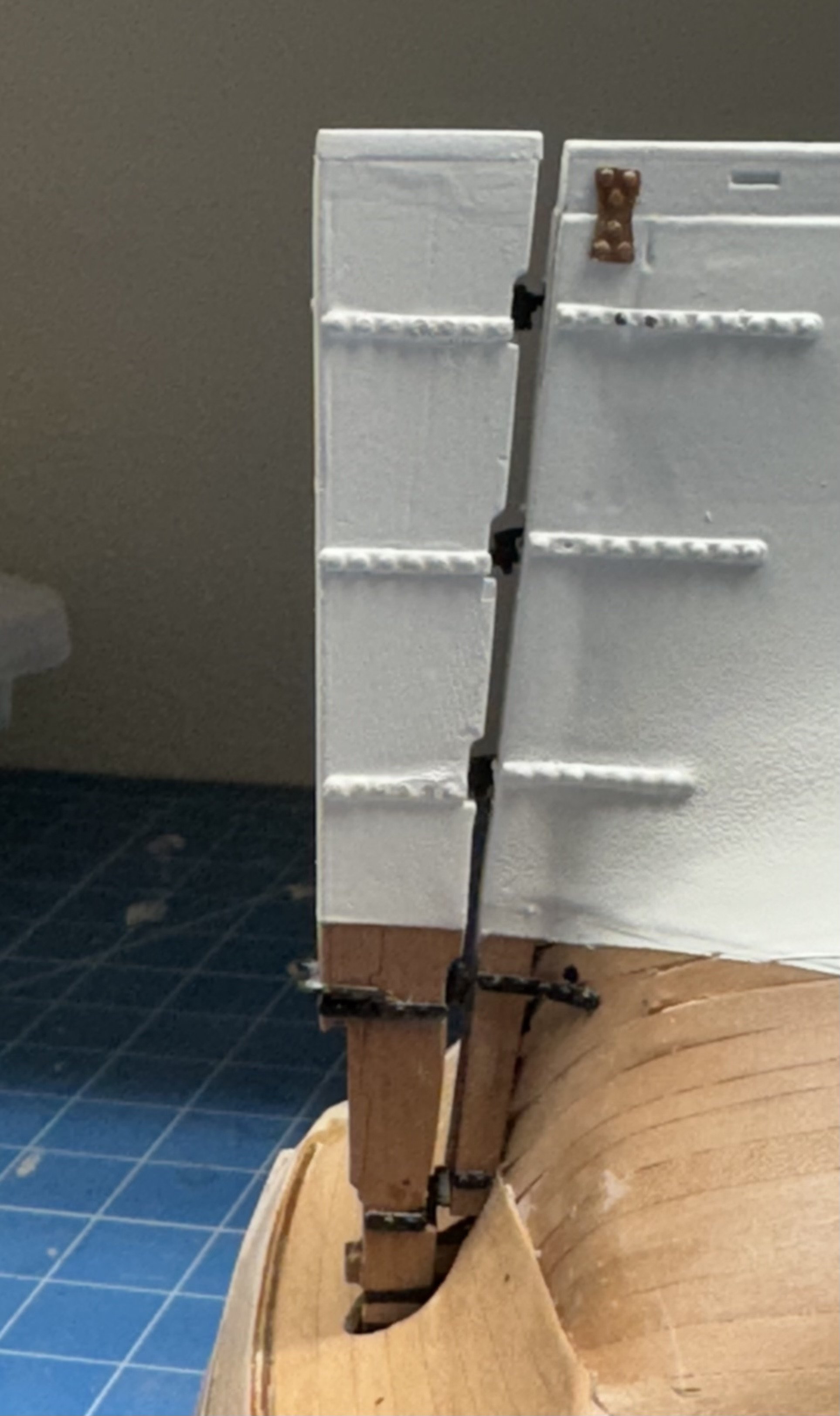
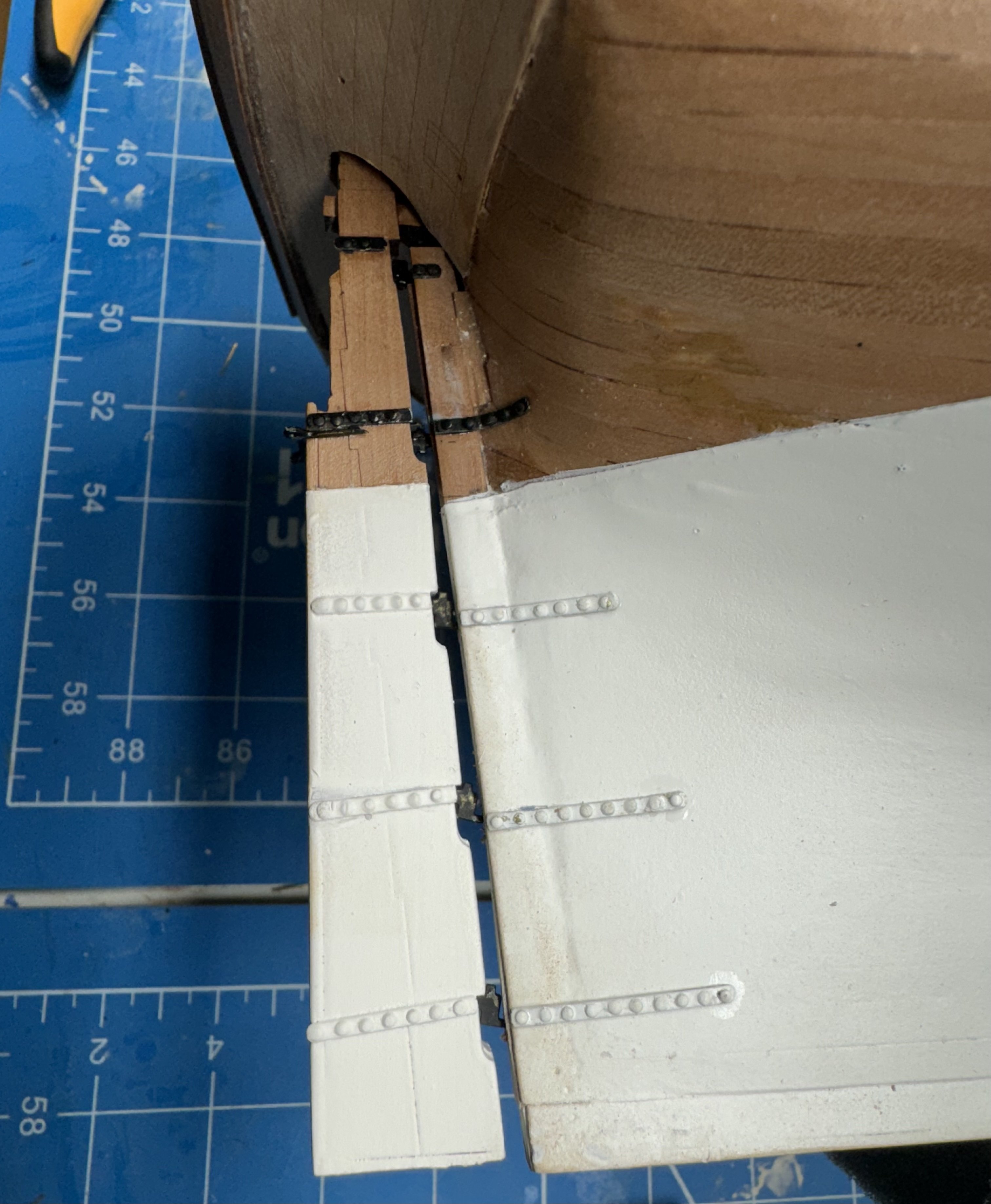
Starboard side rudder gudgeons installed. Using the end holes to locate the plates seems to work out. I did not get the rudder lined out exactly with the keel but it doesn't look as bad when the hull is upright. I am ho;ding off on the fishplates until I get the port side gudgeons installed. I may decide to send the hull back to the paint booth for some touch-up at the stern.

- 422 replies
-
- 4
-
-
- Vanguard Models
- Sphinx
- (and 1 more)
-
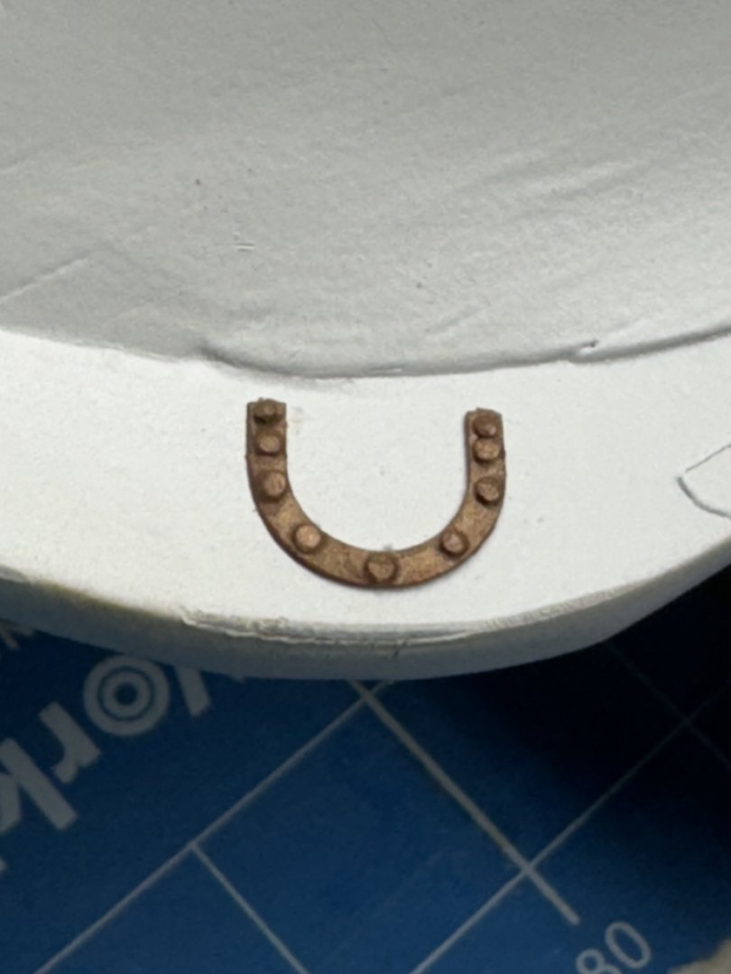
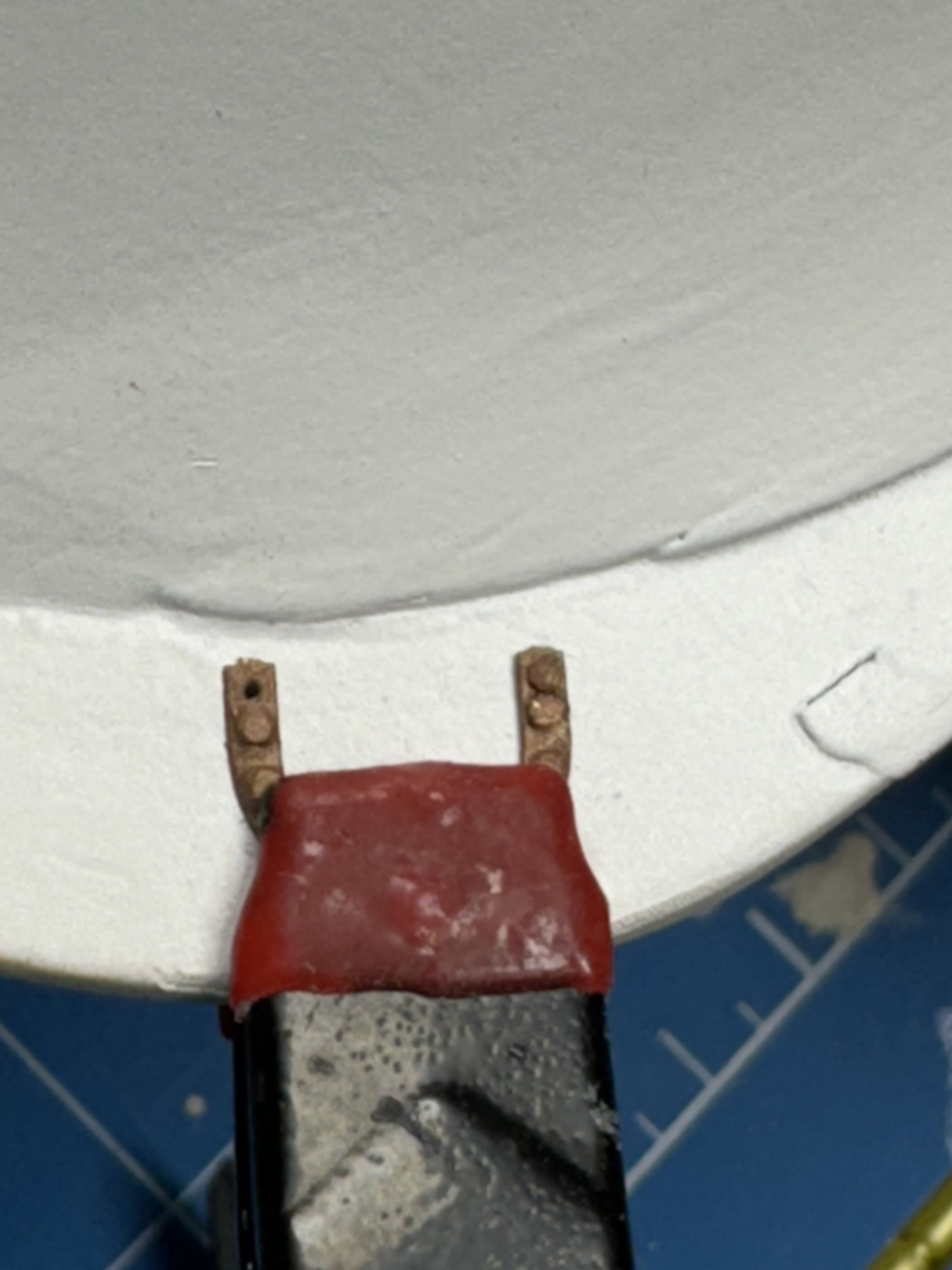
For the rudder gudgeons and the horseshoe and fishplates I modified the above procedure to leave the two outermost holes empty and use them to locate the plate. I thought this especially useful for the gudgoens since they have to be placed on the hull with no locating "holes". I thought the probability of my locating them correctly and drilling all the holes without "issues" to be finite but very small. The rudder is still drying on the hull so took one of the horseshoes for a test run. since it is easy to clamp it in place (unlike the gudgeons). Here is the horseshoe with one "rivet" in place and then the finished installation. I painted the heads of a dozen or so pins copper then cut off all but about 2mm on the shaft (while holding the upper part in needle jaw tweezers) then placed the "remnant" in the hole which had a very small drop of medium CA in/on it. I thought about leaving the glue out but although under no stress if something can go wrong it likely will.

- 422 replies
-
- 5
-
-
- Vanguard Models
- Sphinx
- (and 1 more)
-
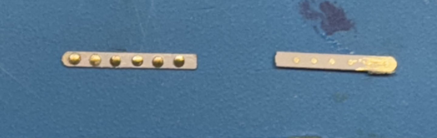
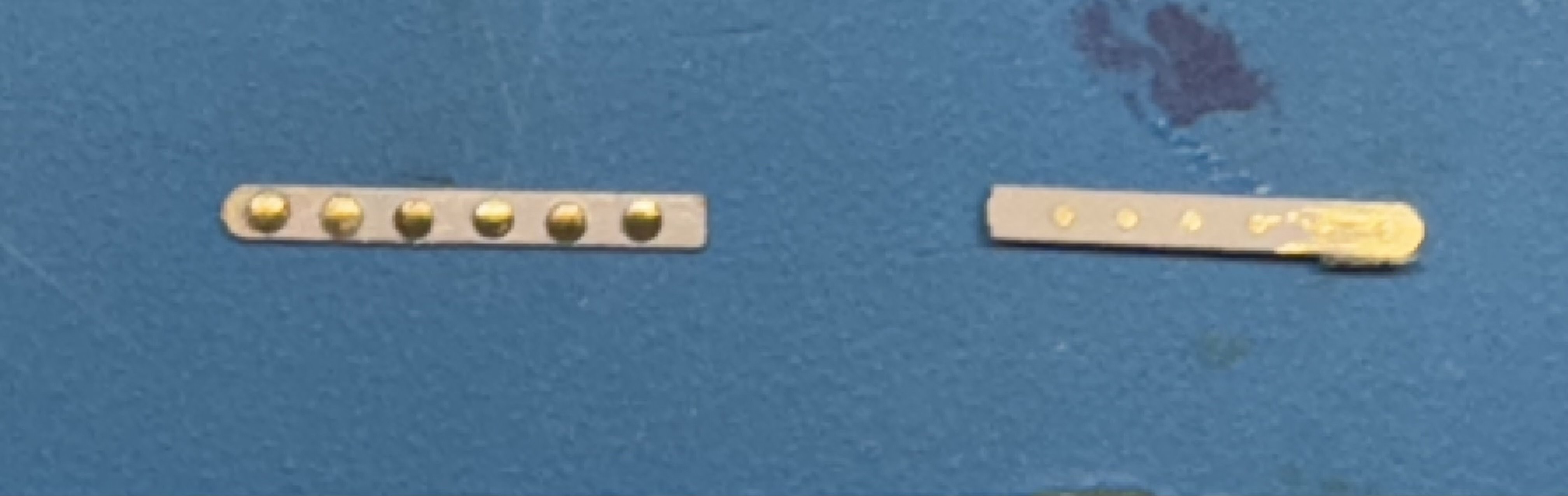
With the hull in the paint booth I decided to revisit the rudder. I have a rudder in the "to be installed" box but remembered there was something not right with it. It would appear that I failed to cut the brass pins short enough and they are forcing the three pieces of the rudder structure apart. Would not as big a deal on the other side but this side SHOWS, To avoid this issue (and potentially create another one) I decided to just use the heads of the pins and create a simple flat plate to glue onto the rudder. Getting them placed correctly now becomes the challenge since the pins are no longer locating the plate. I made the mistake of priming the PE sheet (grey self etching primer) first and then had to drill out the holes so the pins would fit easily. I put the required number of pins in the plate then used thin CA to glue the pins to the plate and when dry (10 seconds) cut the pins off as close to the plate as possible. To reduce any unevenness I ran the plate along a 220 sanding stick a time or three. Here is what on of them looks like Rudder is assembled and waiting for glue to dry. Then we will see how this approach works. If this fails I will have to fill in the opening in the "old" rudder and hope the waterlines are close enough to make adjustment "uncomplicated".
.thumb.jpeg.a2eafa83116990309571bff49b0147ad.jpeg)
- 422 replies
-
- 4
-
-
- Vanguard Models
- Sphinx
- (and 1 more)
-
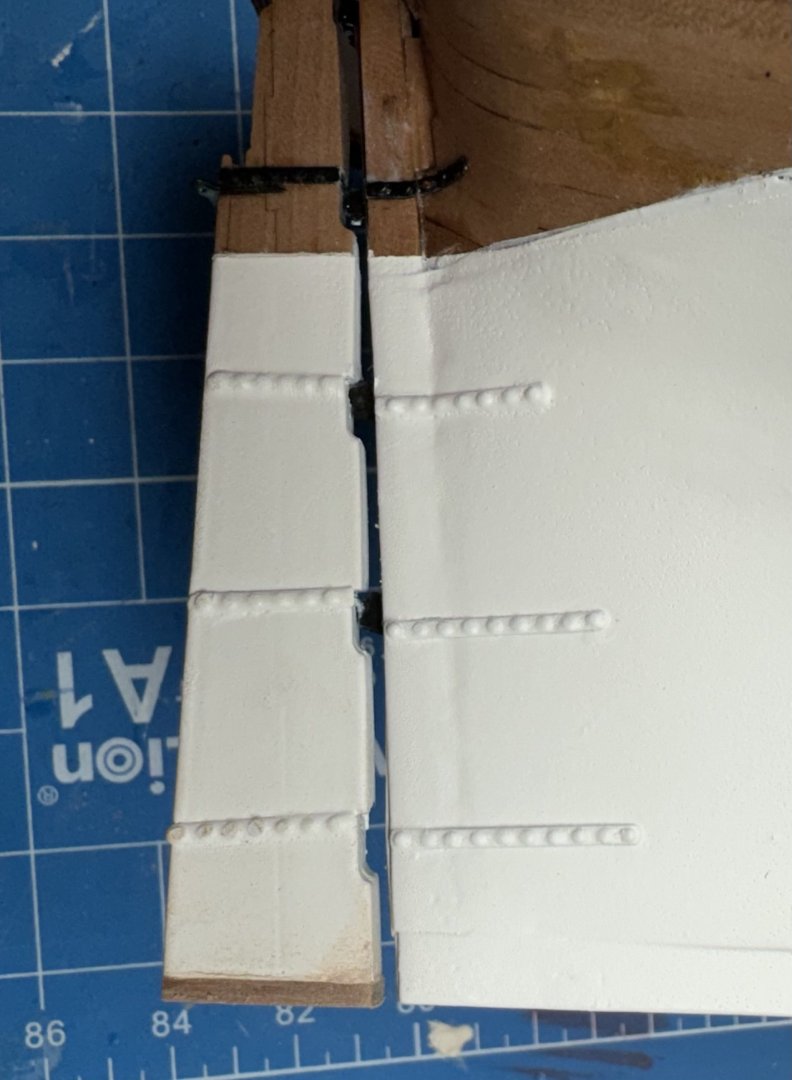
I worked on getting the lower finishing patterns in place one layer at a time. on the starboard side I used a 3mm and 1mm thicknesses for the first two layers. I think the approx 1mm difference in the height of the bulwark between sides made the starboard side (which is higher) be further up and thus created with wider gap above the wales. I am not sure I would recommend the layered approach (as opposed to following the instructions) as trying to sand the lowest part while holding it proved a challenge. In any event, with the help of some filler I got the starboard side q-gallery completed for this stage. To make sure I was at least close to the desired configuration I cut the q-gallery out of plan sheet 14 to use as a template recognizing that it is a 2-D representation of a 3-D object so may not be completely accurate for this purpose but it beats finding out later than this part was significantly too big or small. The port side lower pattern went together just like the instructions suggested (although I did it in layers instead of as a single piece). And I used the kit provided pieces (29 and 45b). I did use any filler (yet) as I want to get some paint on this to see where it might need attention. the multicolored layers make it hard (for me) to get a clear picture of what it REALLY looks like. As you can see from the pictures I have masked off the areas where the molding and channels will go so now it is time to decide about returning the starboard side to the paint booth or press on with painting the upper bulwarks. Paint booth won.


- 422 replies
-
- 6
-
-
- Vanguard Models
- Sphinx
- (and 1 more)


.jpeg.4b04f8e4f06cc7719d1b640be03a5bc9.jpeg)