HOLIDAY DONATION DRIVE - SUPPORT MSW - DO YOUR PART TO KEEP THIS GREAT FORUM GOING! (Only 51 donations so far out of 49,000 members - C'mon guys!)
×


cdrusn89
-
Posts
1,915 -
Joined
-
Last visited
Content Type
Profiles
Forums
Gallery
Events
Everything posted by cdrusn89
-
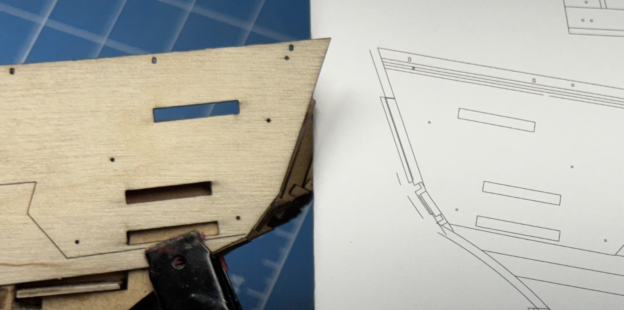
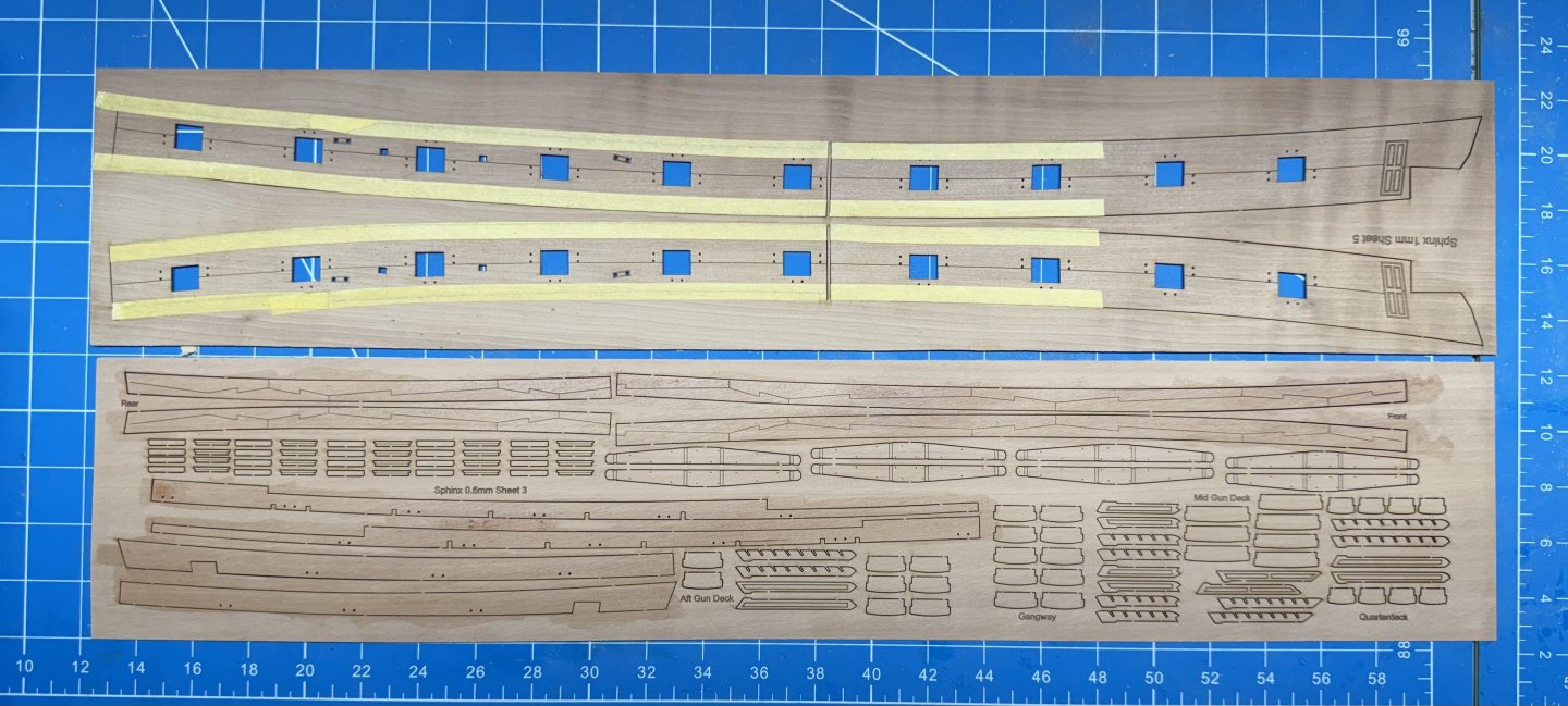
 This time I actually looked at the drawing (Sheet 8 ) which shows exactly where the aft end of the outer bulwark should "land". I am going to glue the bulwark down in stages using full strength PVA so I can get it where the drawing says it should go and aligned with the gun ports. Then on to the planking.
- 422 replies
-
- 4
-

-
- Vanguard Models
- Sphinx
- (and 1 more)
-
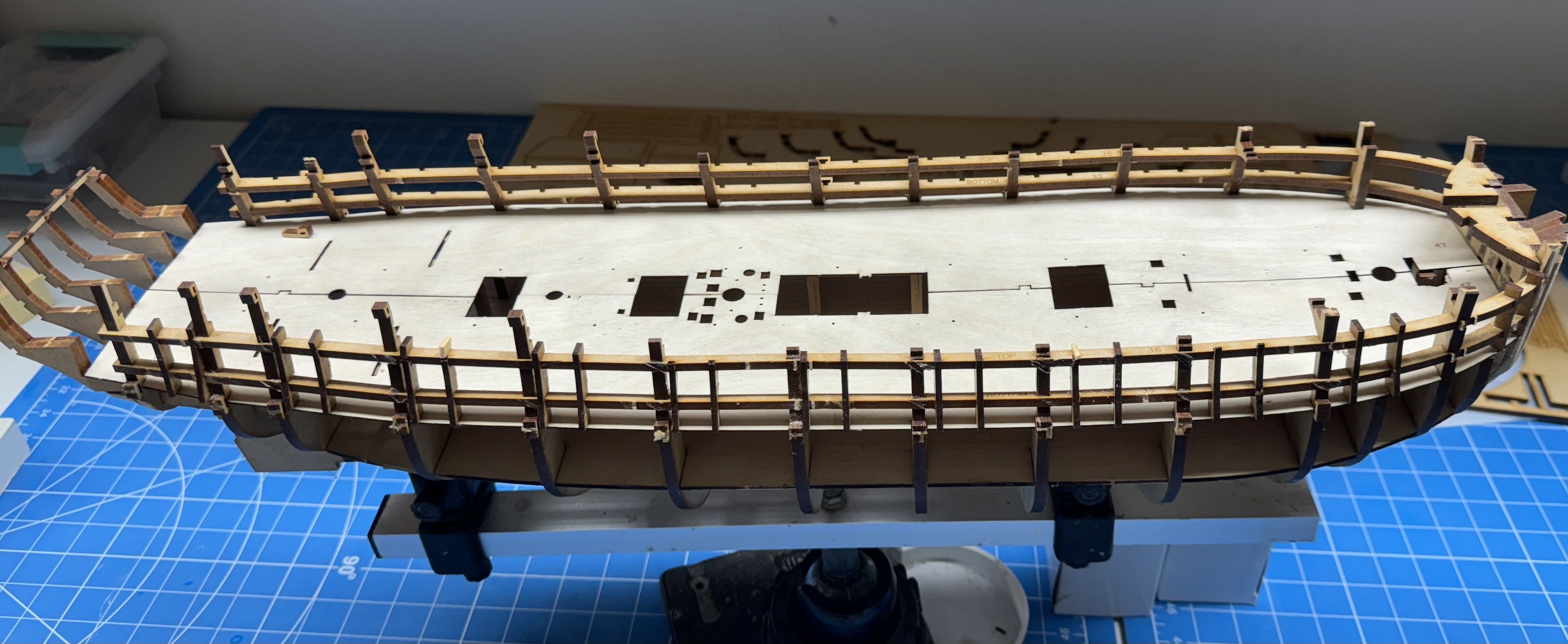
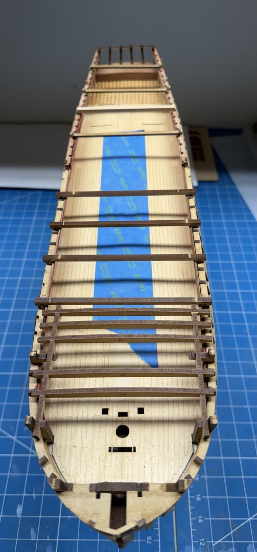
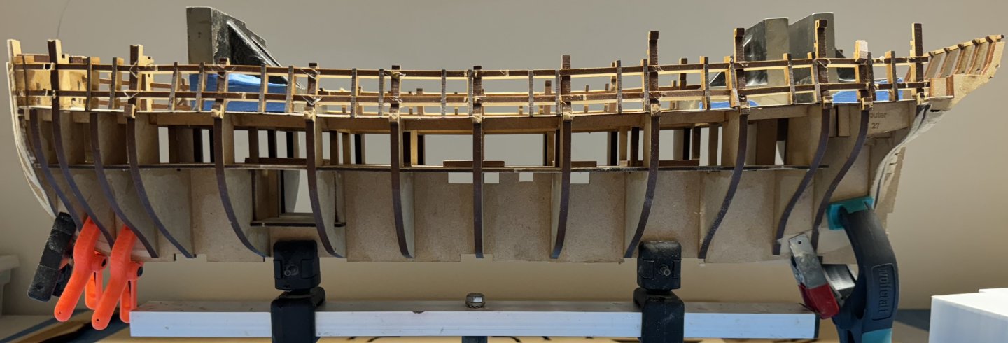
Interior "furnishings completed, hull has been "well and truly" fared. Blue tape is to keep debris from falling "below decks" once the bulwarks are in place - which is next. I managed to break off each and every bulkhead extension while manipulating the hull for faring. I only broke one on the first go round so I am clearly getting more "ham-handed" as I age, even over just a few months. I added my own supports to replace the "stiffeners" that would have connected the bulkhead extensions if they were still there. Hopefully they will do a good enough job but since there is no full size drawing of the bulkheads I am, not willing to try and recreate the extensions from just the MFD carrier sheet - I tried one and it did not go well so... Now for where I went wrong the first go round - Have to ensure the exterior bulwarks are installed correctly, or if I can't have and least consistently incorrectly.
- 422 replies
-
- 6
-
-
- Vanguard Models
- Sphinx
- (and 1 more)
-
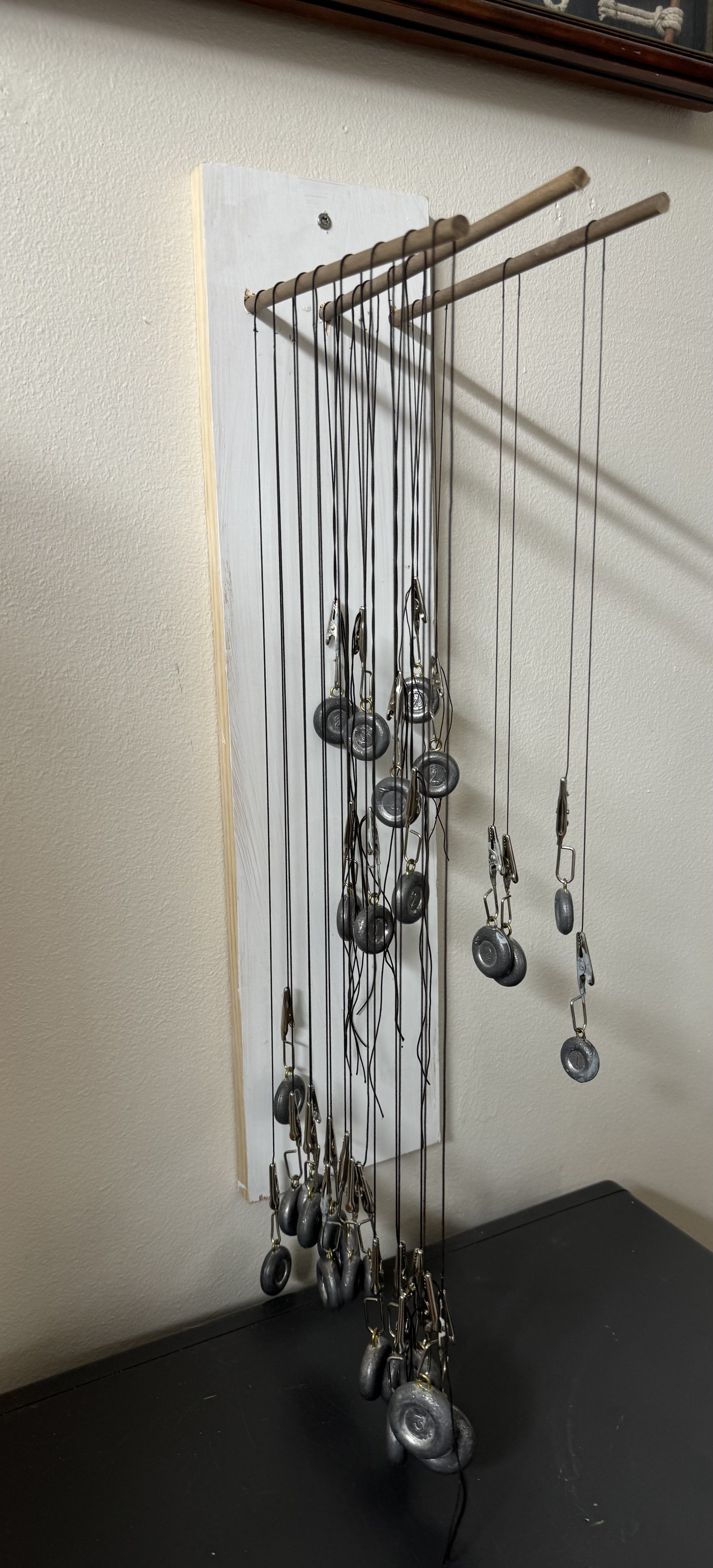
I decided a bit ago to use the serving machine I have to serve the shrouds and stays and have been working my way through them in between working on the hull. The main and fore lower shrouds are served (as best I understand things) at the center of each pair where they are around the top of the masts. I worked this out to be about 2" or 1" each side of the shroud center. Except for the forward most shroud which is served its entire length as this shroud is subject to chaffing by the main or fore course sails. At the mizzen the foremost shroud is not served its entire length as there is no equivalent sail flown from the mizzen. On the mainmast there are 8 shrouds so four pairs one of which on each side is served over half its length plus 1". On the fore mast there are 7 shrouds so three pairs plus a single which is generally the forward most one so this is served over its entire length. Exactly how this single shroud is attached at the mast top is a topic which needs further investigation on my part. After I served the middle 2" I hang the shroud on my "shroud hanger" to get the twist out of the line and to straighten out any "kinks" that may have worked there way into the line while it was being served. This is especially the case where the line is served over more than a few inches as the served line has to be moved to allow more line to be available for serving and this means bending the served line around the line holder which is definitely a source of "kinks". So here in my "shroud hanger" with the current complement of shrouds. I still have make the pairs for the main mast with half the line served but with those I will have all the lower shrouds "done" this far. I still have to make the Burton pendants and of course the top mast and top gallant shrouds but these are not served, at least on my model.

- 422 replies
-
- 2
-
-
- Vanguard Models
- Sphinx
- (and 1 more)
-
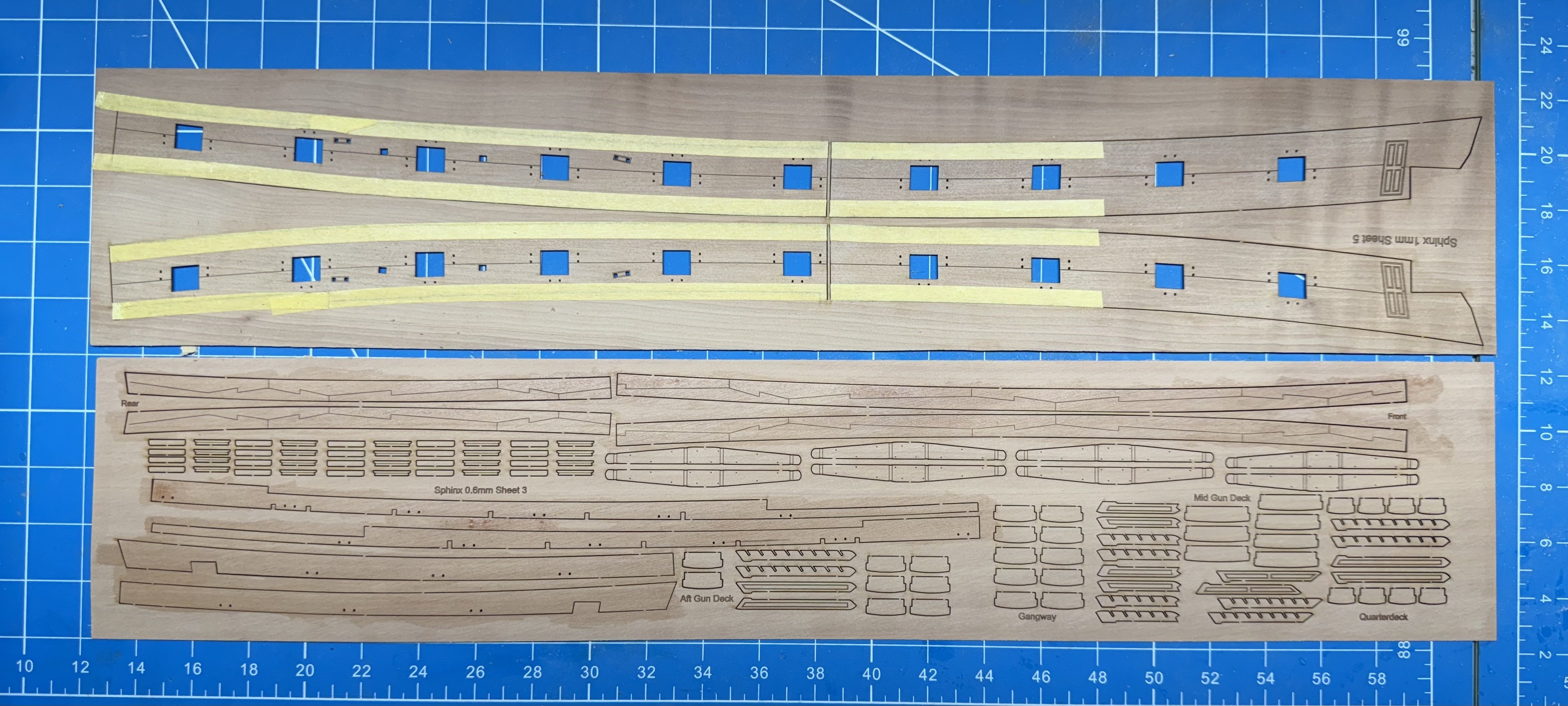
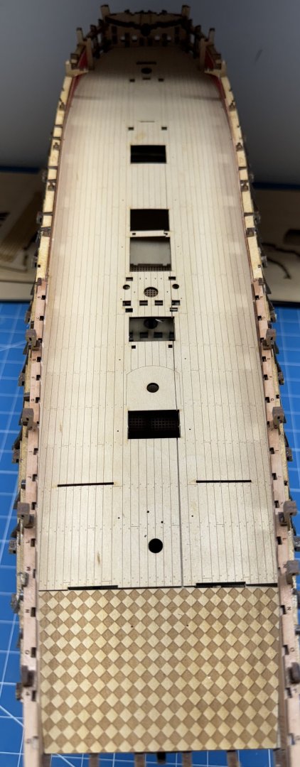
The aft bulwarks were more of a struggle than the fore. Probably because the sub-deck did not completely meet the keel/bulkheads at the aft end I had to reduce the height of the bulwarks to get them to fit under the beam spacing patterns. I will need to be careful when adding the q-deck beams to make sure they all seat correctly. With the aft bulwarks in place I tried to fit the gun deck planking sheet. As I remember from Sphinx #1 I had to take a considerable amount off the edges of the planking sheet to get it to fit. I almost got to the scupper holes (I assume that is what they are) in reducing the width. Similarly with the checkered planking. At the end of the day I managed to split the planking sheet toward the aft end and was not successful in getting the gap completely closed before the glue set up. For those who follow maybe dampening the planking sheet before bending it to get it to fit inside the bulwarks would reduce the potential for cracking or adding a did piece of masking tape on one side. Not sure that either would work but the more times you have to fit the planking into the hull the more chance of the planking sheet cracking along one of the laser lines. So I have a visible crack in the decking although it is aft where it will not be all that noticeable. I also managed to break off the thin piece of decking between the hatch and companionway forward of the main mast. I will save the piece and install when the hatches are in place. Maybe add a small ledge on the forward/aft end of each coaming to support the planking piece. On to the spirketting and deck clamps.
- 422 replies
-
- 3
-
-
- Vanguard Models
- Sphinx
- (and 1 more)
-
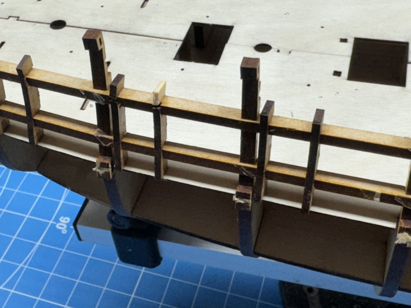
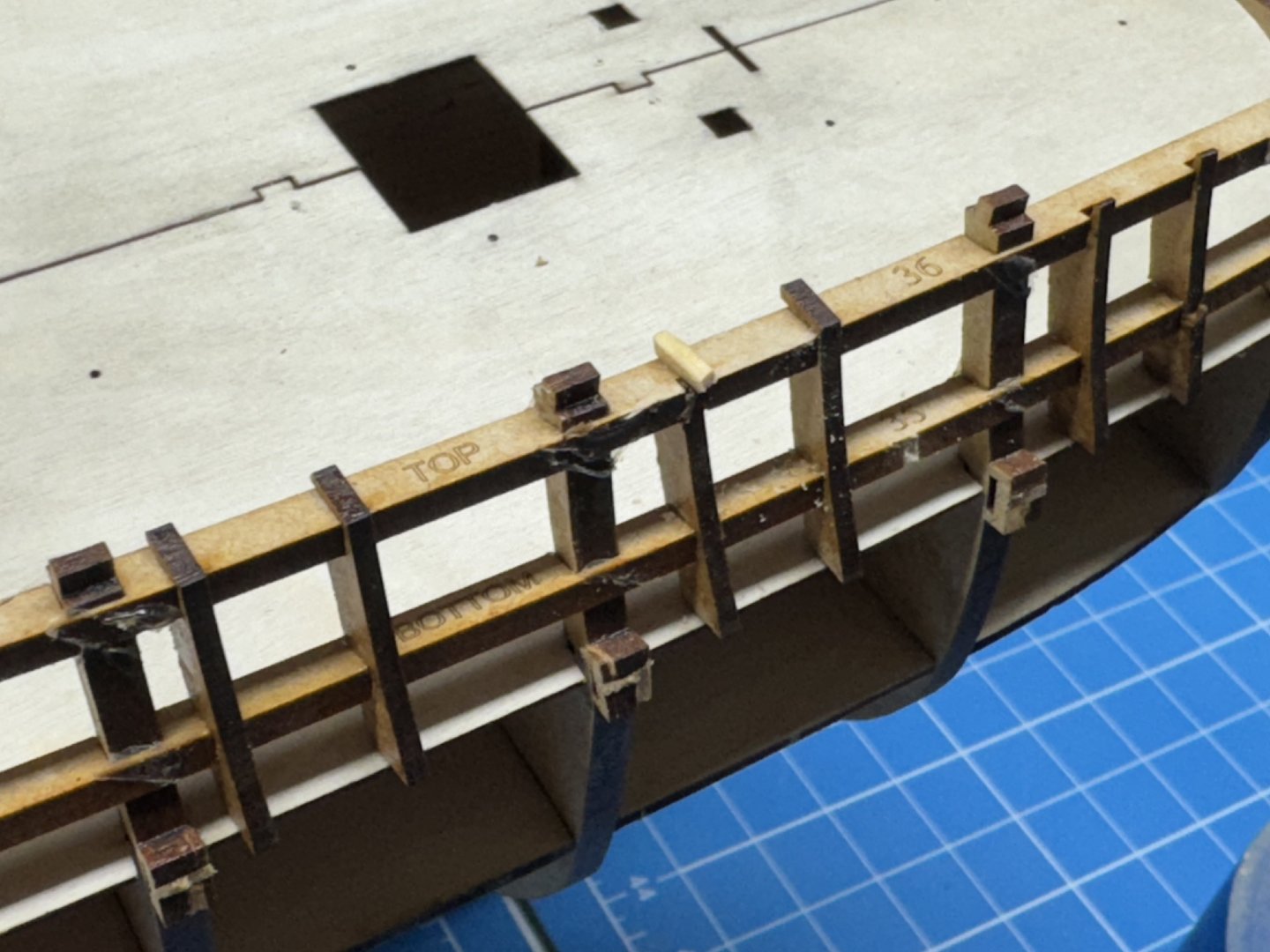
Both forward bulwarks and the q-deck beam spacing patterns installed and glue drying. I had two occasions in the beam spacing patterns where the slot in the bulkhead was partially blocked by the top of the gun port frame. Taking Chris's word that these have no function I removed the two offending items and got the beam spacers installed correctly (I hope). When to glue is dry it is on to the aft bulwarks.
- 422 replies
-
- 5
-
-
- Vanguard Models
- Sphinx
- (and 1 more)
-
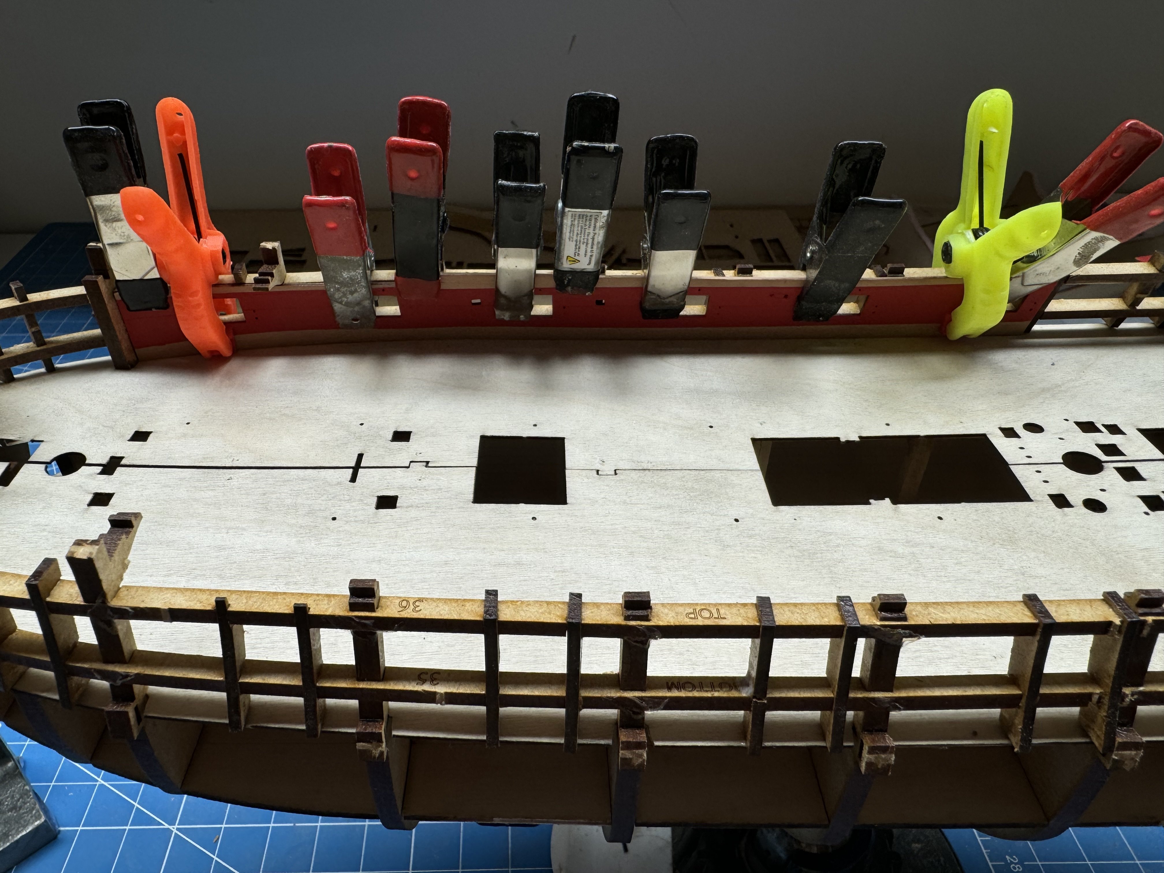
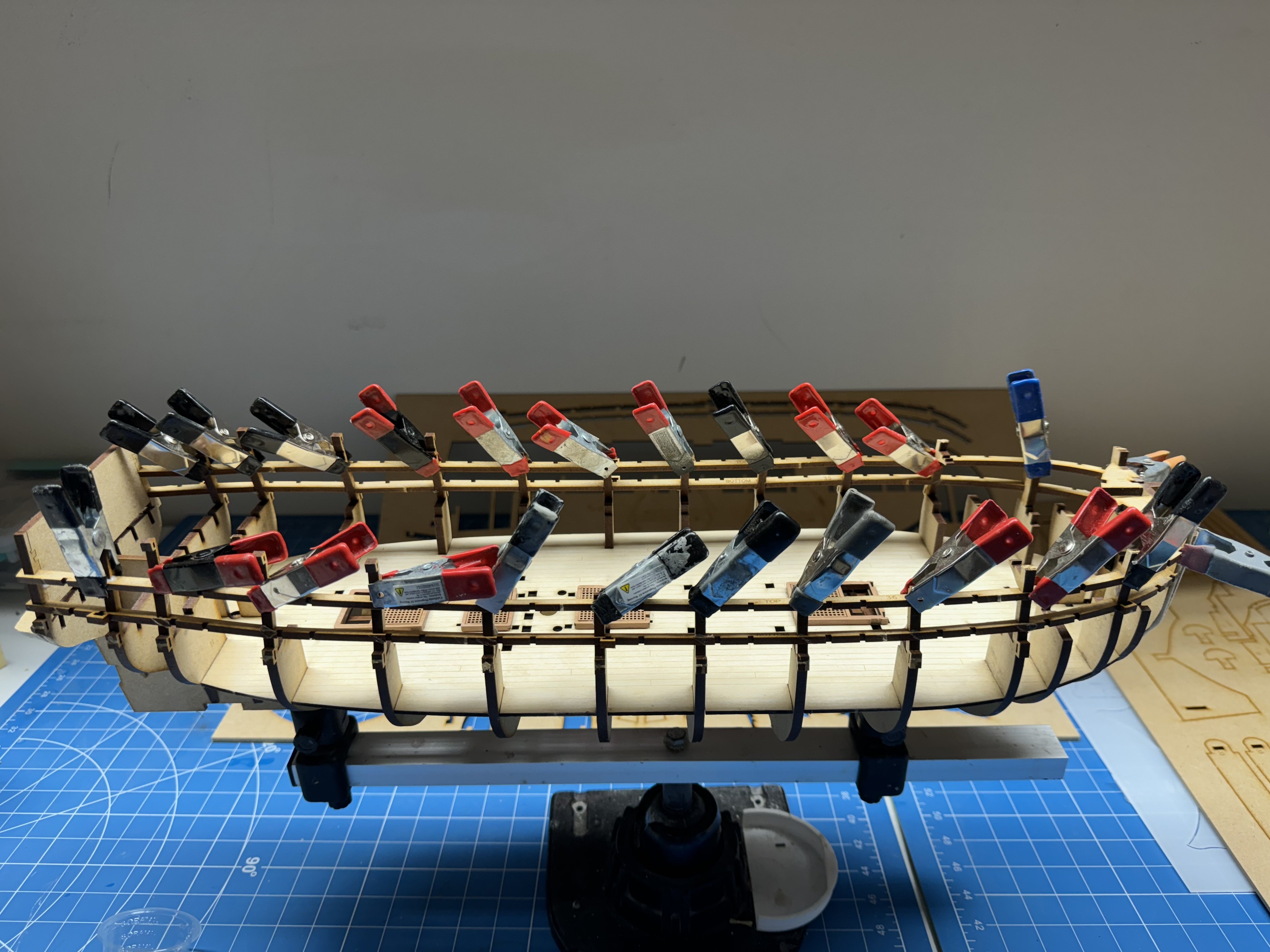
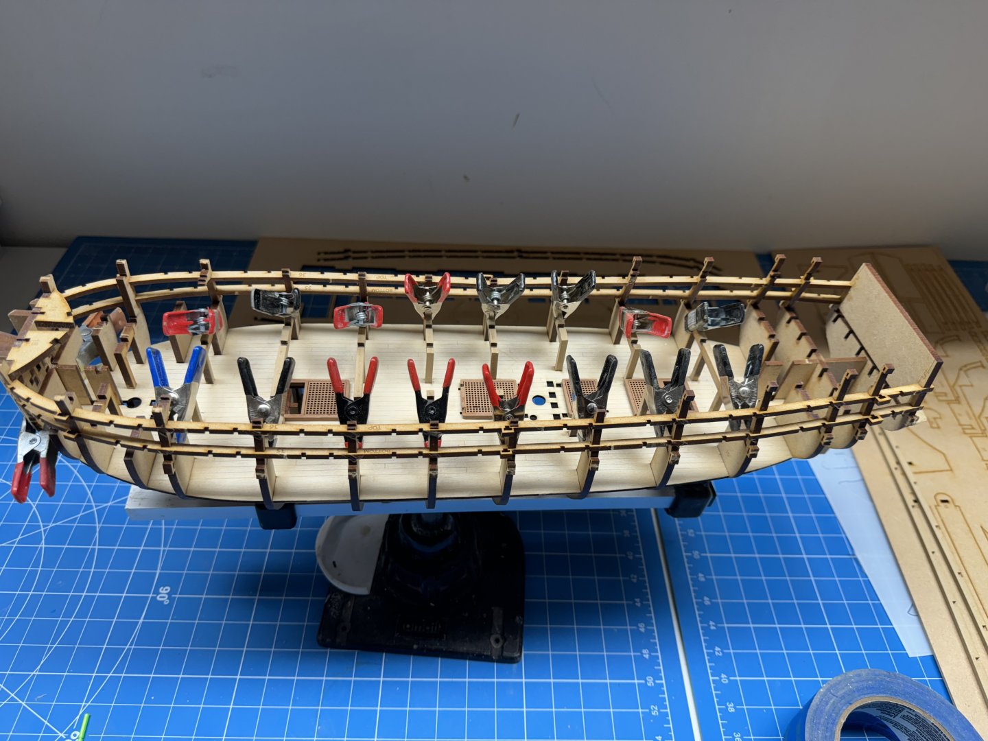
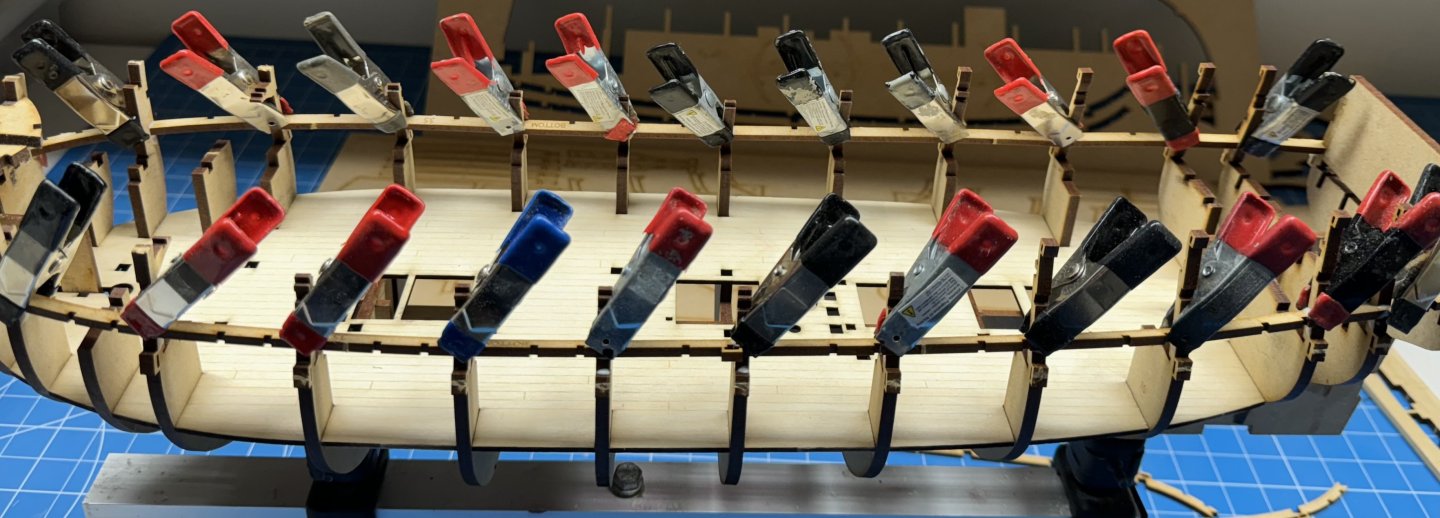
Pre-painted forward bulwark, starboard side in place and glue drying. Using a brush to apply the dilute PVA identified some places where the bulwark was not in contact with the framing and I applied another clamp to (hopefully) correct.

- 422 replies
-
- 5
-
-
- Vanguard Models
- Sphinx
- (and 1 more)
-
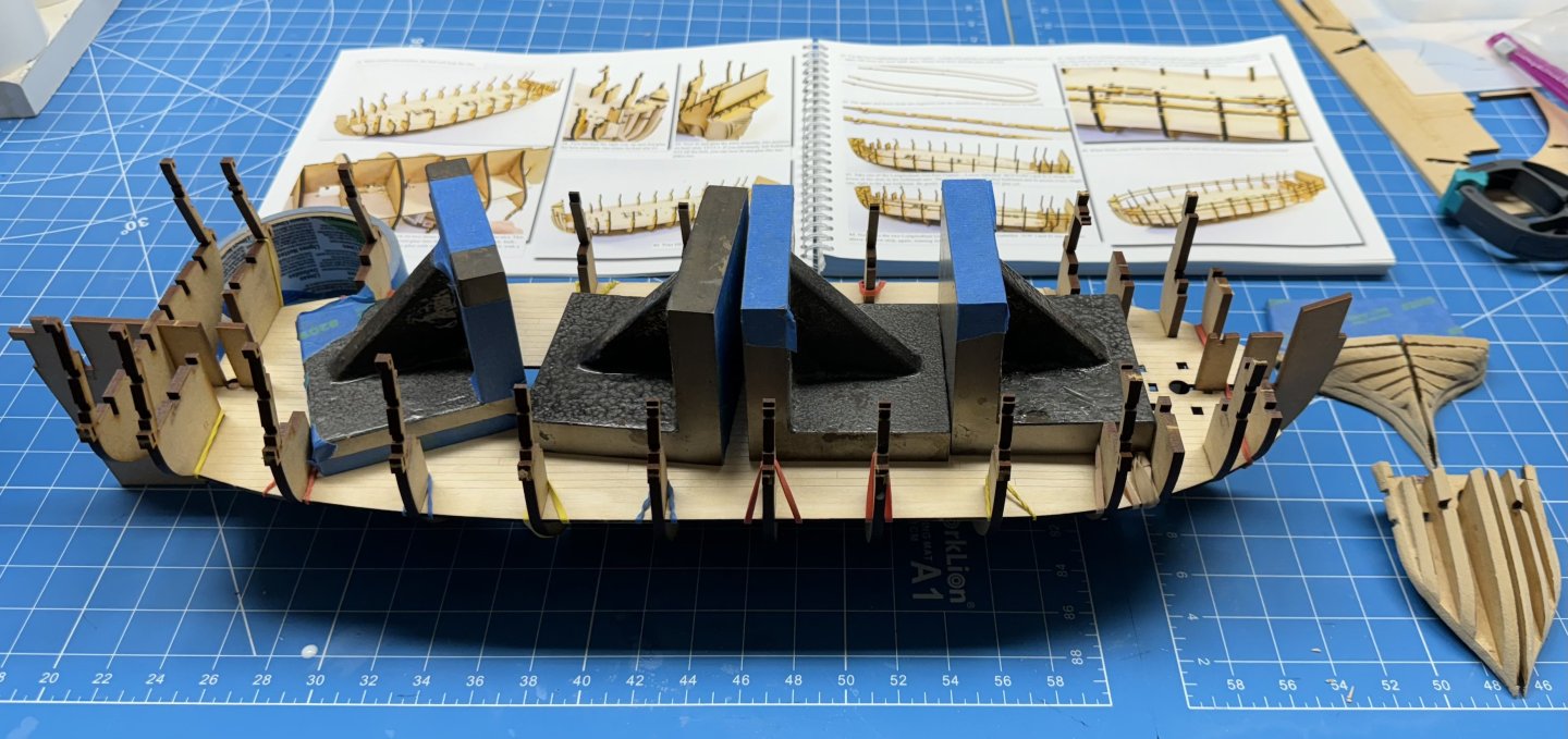
I got the bow and stern fillers fared to the hull and glued on. Don't ask me how I know but it is possible to dislodge the decking by pushing the aft stern filler up too far. That accounts for the weights on the deck - need both fore and aft to keep the Amati holder from tipping over. Don't ask me how I know that either. With a few minutes to kill while the glue dries I masked off the inner bulwarks in preparation for painting. I applied a coat of polycrylic clear flat to all the bulwarks, deck clamps and spirketting to get a good foundation for paint, or in the case of the aft areas that will not be painted as a first layer of protection against ham handed (or sloppy) model builders.
- 422 replies
-
- 6
-
-
- Vanguard Models
- Sphinx
- (and 1 more)
-
Thanks Chris - I managed to get the starboard side done without breaking any.
-
Starboard side gun port frames installed. It took some "finesse" to get them all the way into the horizontal stringers. I now also remember that they are pretty fragile and it is entirely possible to break off the top portion of the frame, especially where they are quite thin (GPs 4, 5 and 6). I broke off two and fashioned replacements for the top portions out of Alaskan Yellow Cedar. My previous experience indicates that these will not "show" and I find it much easier to shape the AYC than the MDF of which the frames are made. Here are the two replacement pieces. It remains to be seen if the white glue (full strength) will effectively bind these small pieces to the rail to withstand the shaping which is coming pretty soon.

- 422 replies
-
- 3
-
-
- Vanguard Models
- Sphinx
- (and 1 more)
-
Gun deck support beams in place and drying. No mention is made in the instructions about removing the laser char and the pictures in the instruction book show the beam supports with the laser char in place but I took it off anyway. Seems it should improve adhesion of the gun deck when we get there (which is only a few pages ahead. Similarly for the longitudinal beams. Removing the char also removes the "cant" since the laser does not cut at precisely 90 degrees, but I probably put an inconsistent "cant" when removing the char so...
- 422 replies
-
- 3
-
-
- Vanguard Models
- Sphinx
- (and 1 more)
-
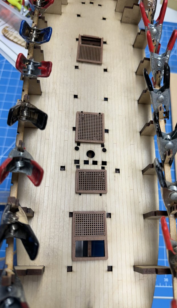
I hope the order of installing the upper and lower gun port frames does not really matter. Given my desire to clamp each and every bulkhead riser to the frame I did both the lower ones first as the clamps would interfere with the upper frames. Did I mention you can't have too many clamps. I also fabricated the hatch coamings and gave them a coat of Polycrylic Clear flat. They are just sitting on deck at the moment. I intend to pay particular attention to the various opening in the deck adjacent to the coamings. Given what I know now, blocking these opening, even slightly will cause significant headaches in the future with little recourse since there will no way to get at them without a good bit of "collateral damage".
- 422 replies
-
- 4
-
-
- Vanguard Models
- Sphinx
- (and 1 more)
-
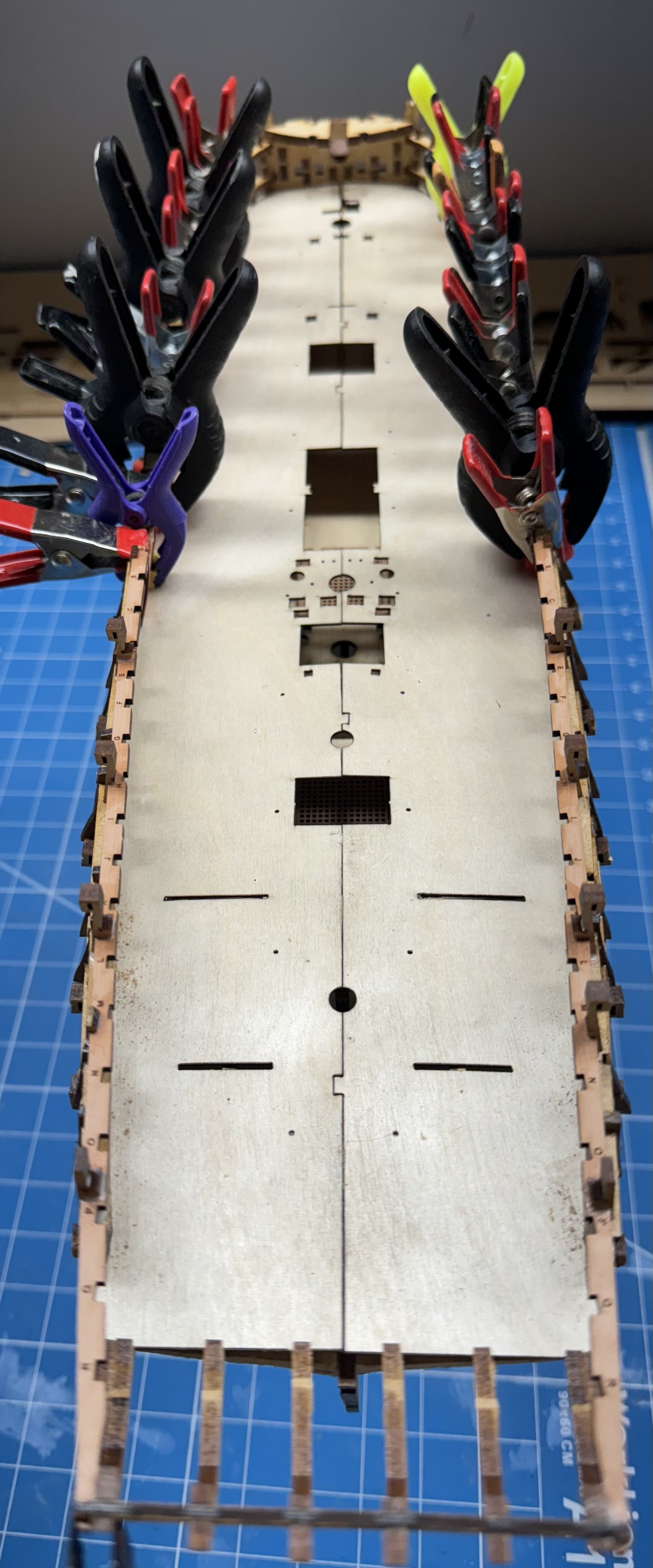
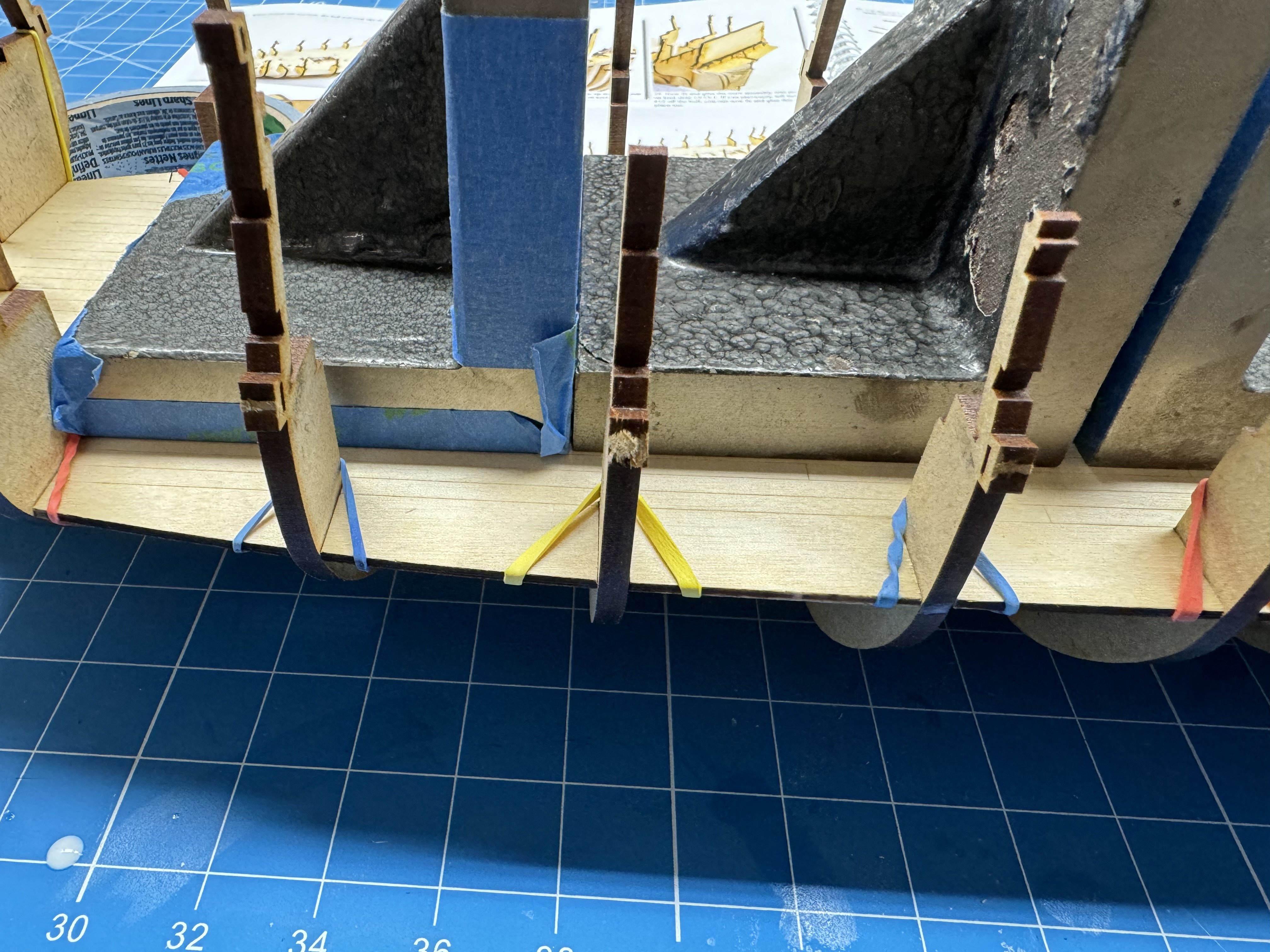
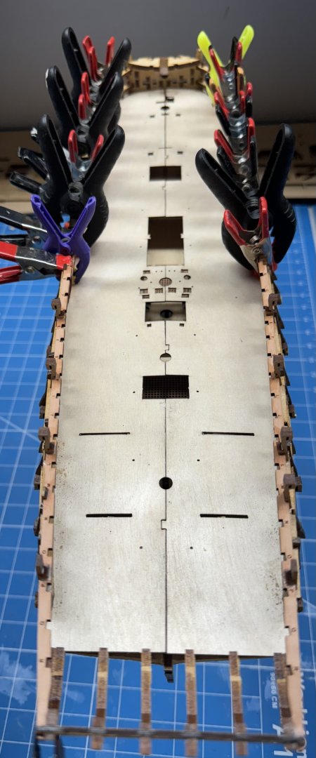
Getting the decking to "slide" down onto the keel/bulkheads was not as easy as I remember it from the first time. I ran a 100 grit sanding stick inside each of the deck "notches" (use up and down 2 or 3 times - took some of the char off) before I could get it down "fore and aft". To increase the chances of getting a good bond between the decking and keel/bulkheads I stretched a rubber band around each bulkhead with the edges stretched out to pull the decking down to the bulkhead. I "painted" the bulkhead/deck junction with 60/40 PVA/H2O and then turned the hull over and weighted the decking down as I noticed while painting glue that the deck and keel/bulkheads were not firmly mated at the center. I will let this dry and then work the keel bulkhead junctions which are pretty tight without glue. I needed a small hammer to "help" some of the bulkheads to seat completely.

- 422 replies
-
- 3
-
-
- Vanguard Models
- Sphinx
- (and 1 more)
-
Thanks Jacques. Makes me want to try another "small" Vanguard kit but I have Sphinx and Indefatigable "in the Que" so it may be sometime before I am able to work another "small" Vanguard.
- 42 replies
-
- 1
-
-
- Saucy Jack
- Vanguard Models
- (and 1 more)
-
And while going through the material in the box I noted that there were four anchors (maybe 3-D printed) in the fittings box. Presumably these would replace the MDF anchors that are still on the carrier sheet. No mention of them in the instruction manual that remains "Revision 2". Is there someplace on the Vanguard site that updates the manuals as the material provided changes?

- 422 replies
-
- 1
-
-
- Vanguard Models
- Sphinx
- (and 1 more)
-
Saucy Jack is done and the "new" Sphinx is about to begin. I put all of the "other" Sphinx stuff back in that box (including all the plans) so there is no chance of my being caught by a plan or instruction manual update unawares. So back to page 1 and hopefully this time pay more attention to how things fit on each side. Seems that is REALLY important.

- 422 replies
-
- 4
-
-
- Vanguard Models
- Sphinx
- (and 1 more)
-
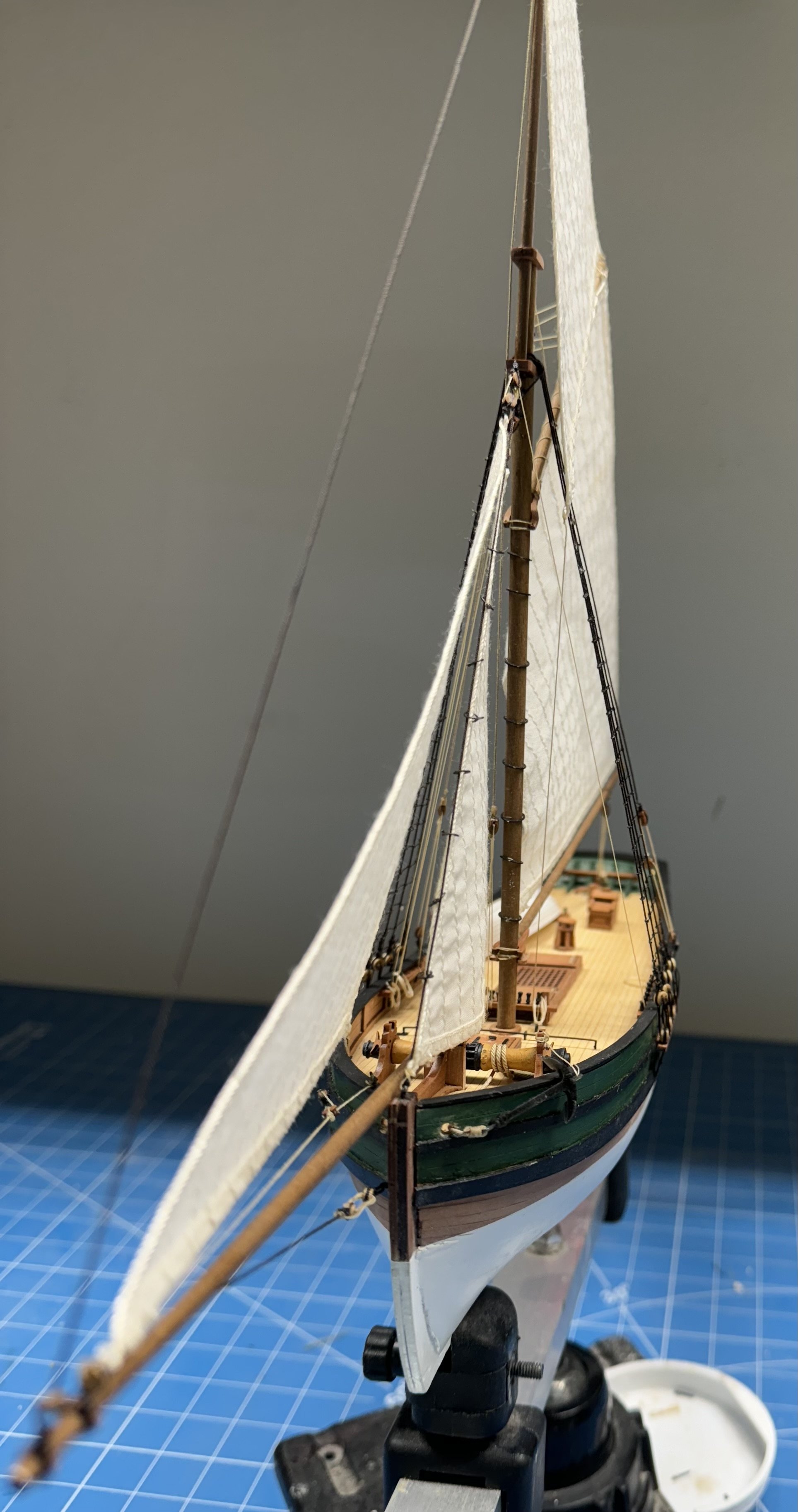
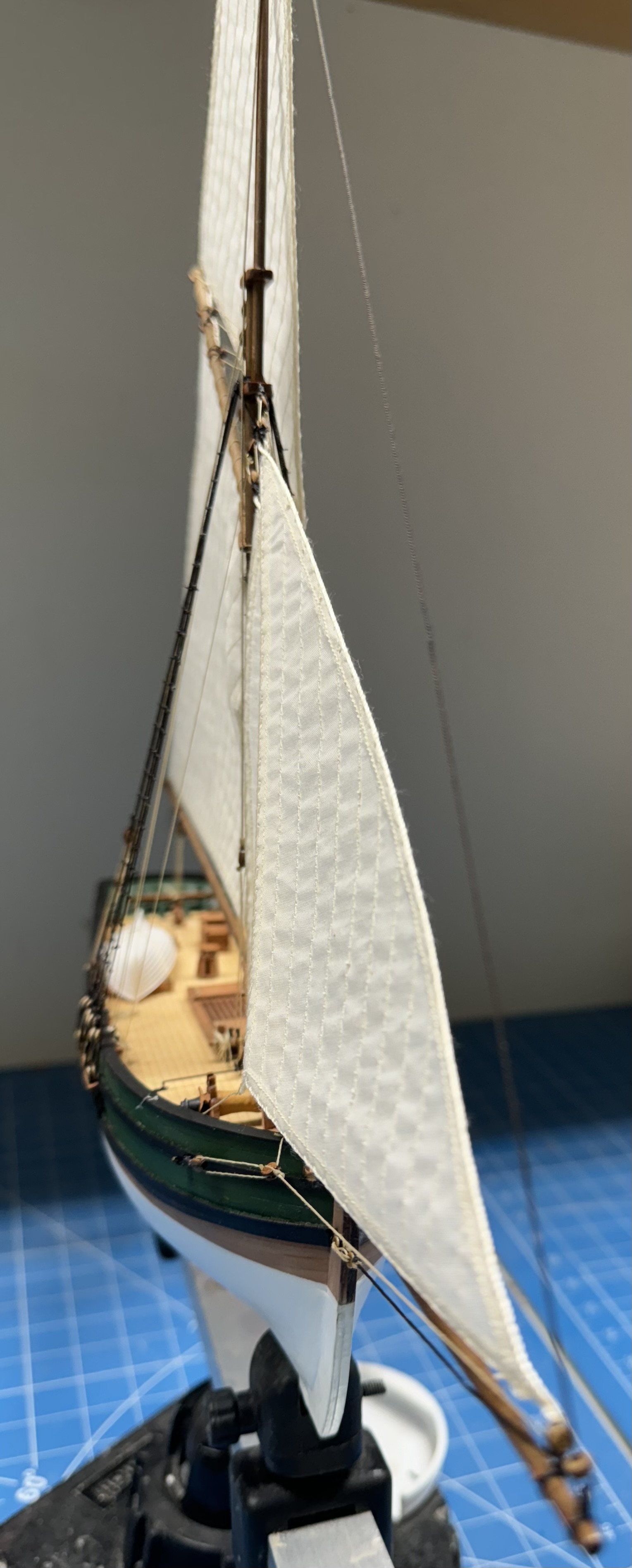
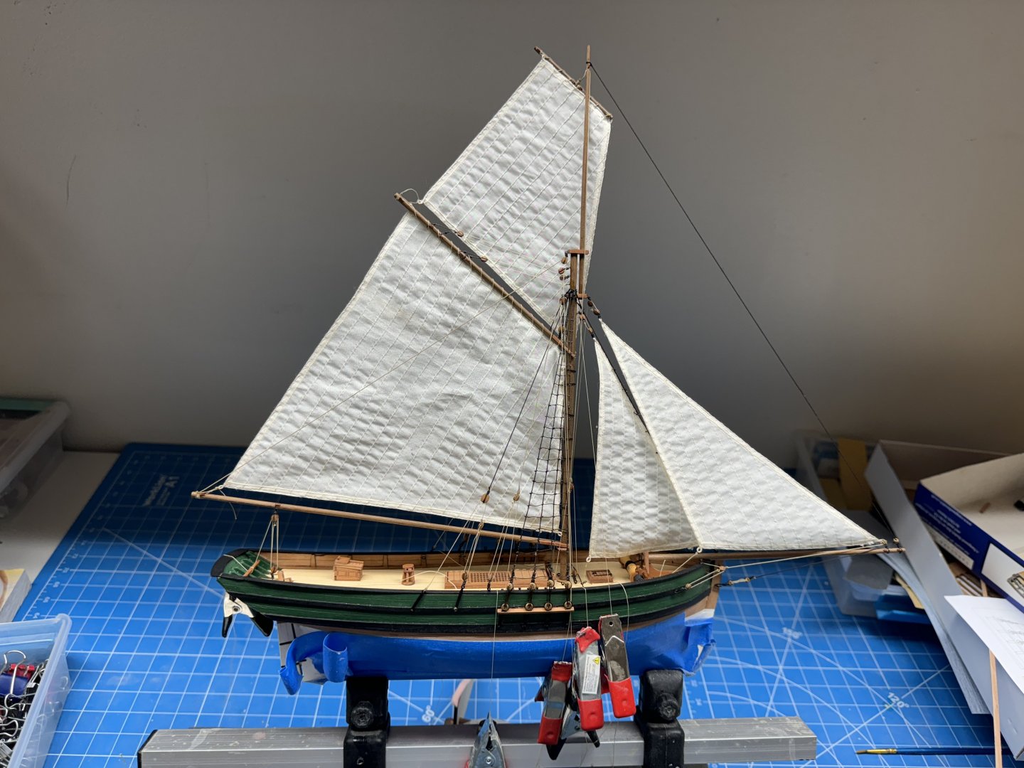
Saucy Jack is headed for the display case. I will denote this build log as "Finished" once I figure out how exactly to do that. Here are a bunch more pictures.


- 42 replies
-
- 7
-

-
-
- Saucy Jack
- Vanguard Models
- (and 1 more)
-
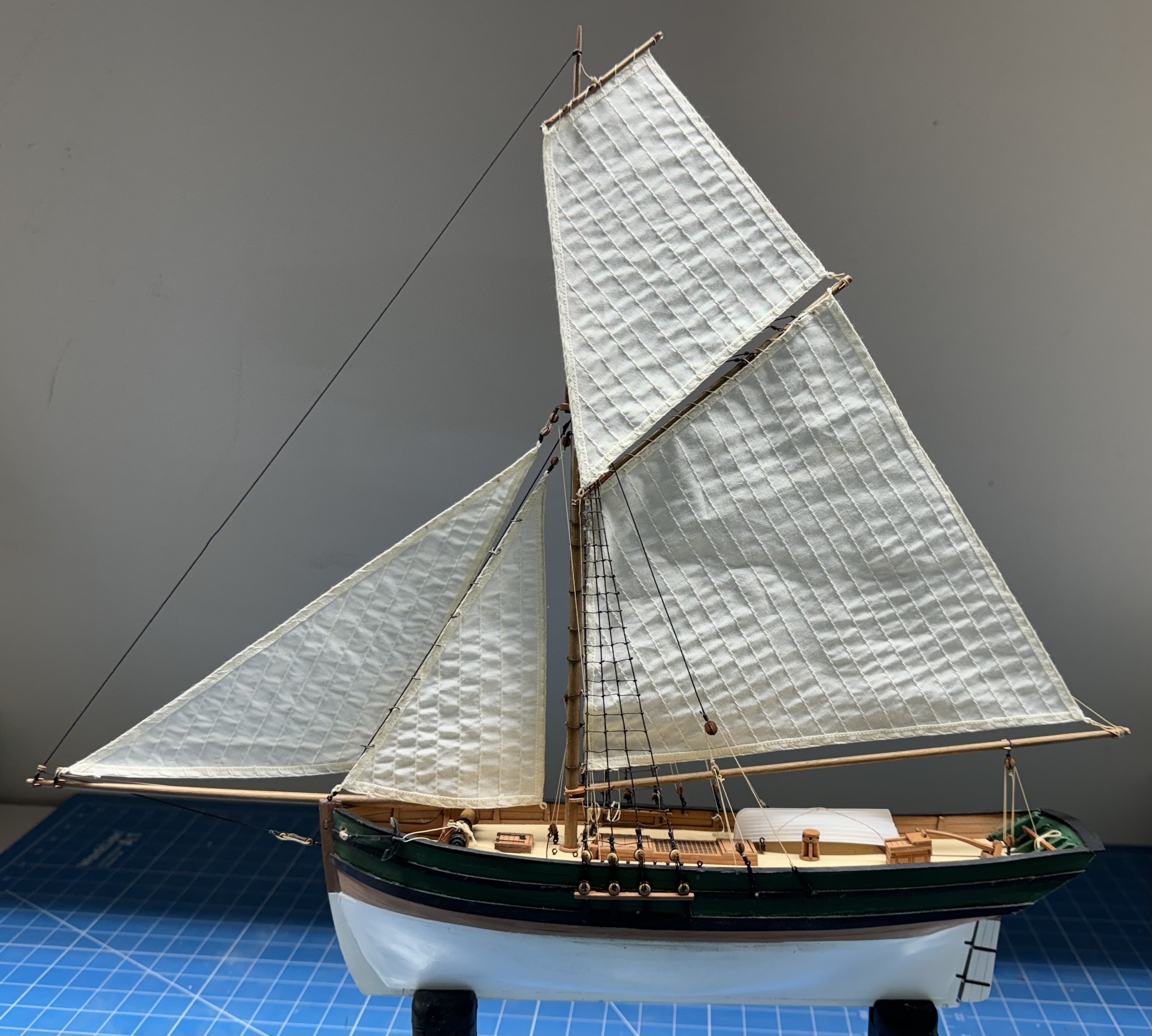
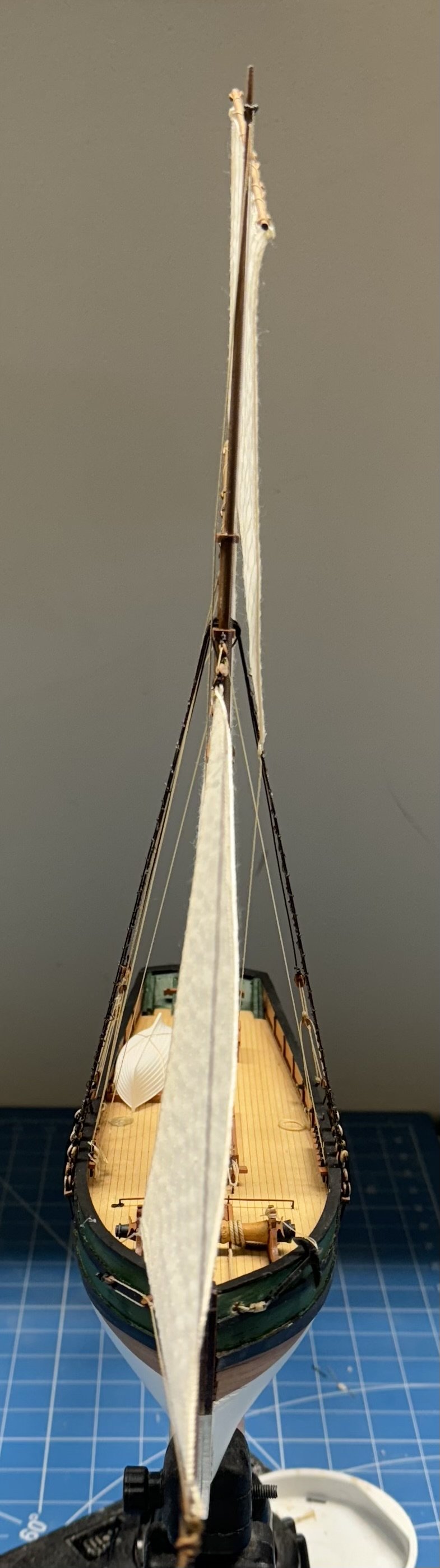
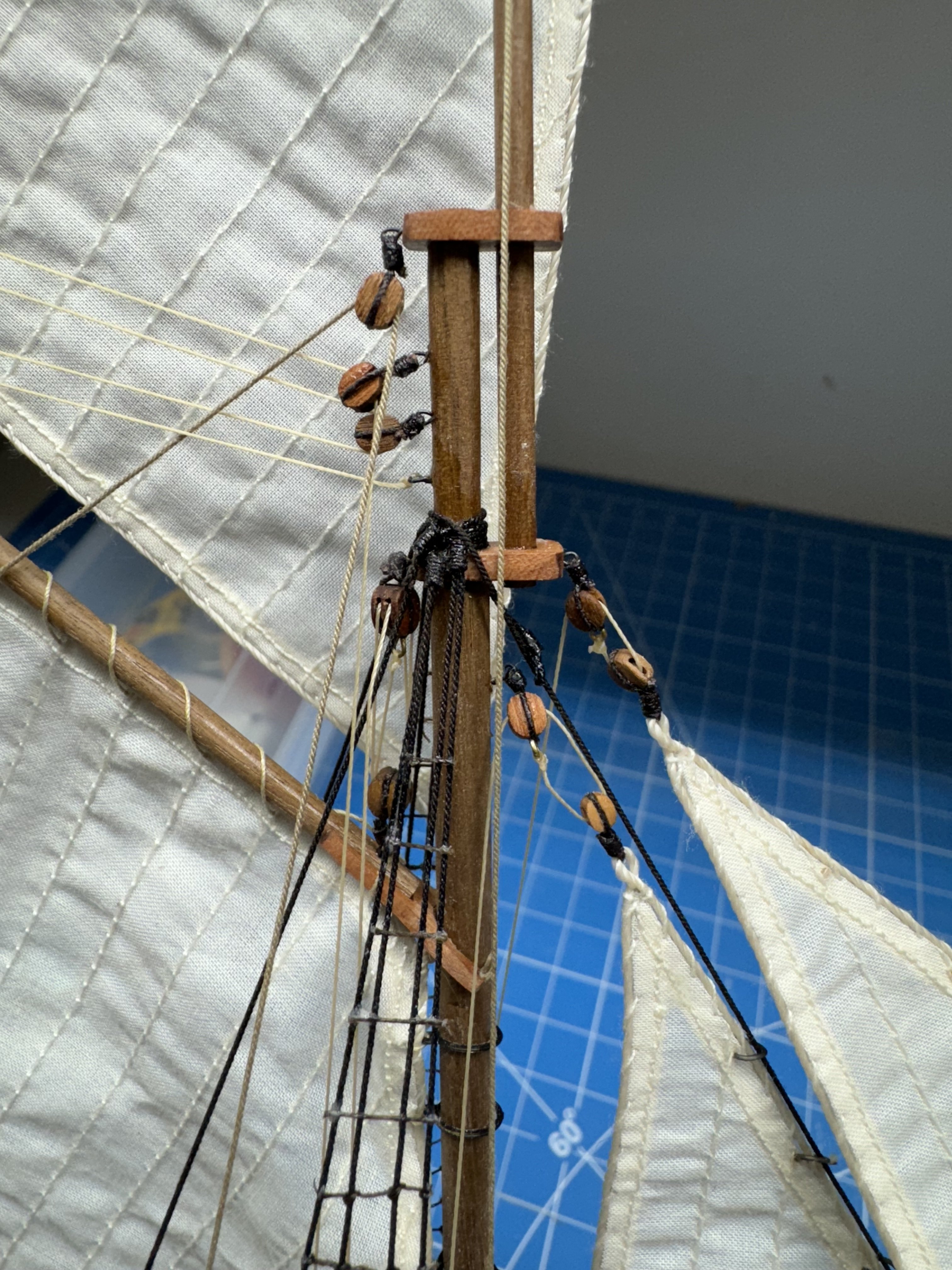
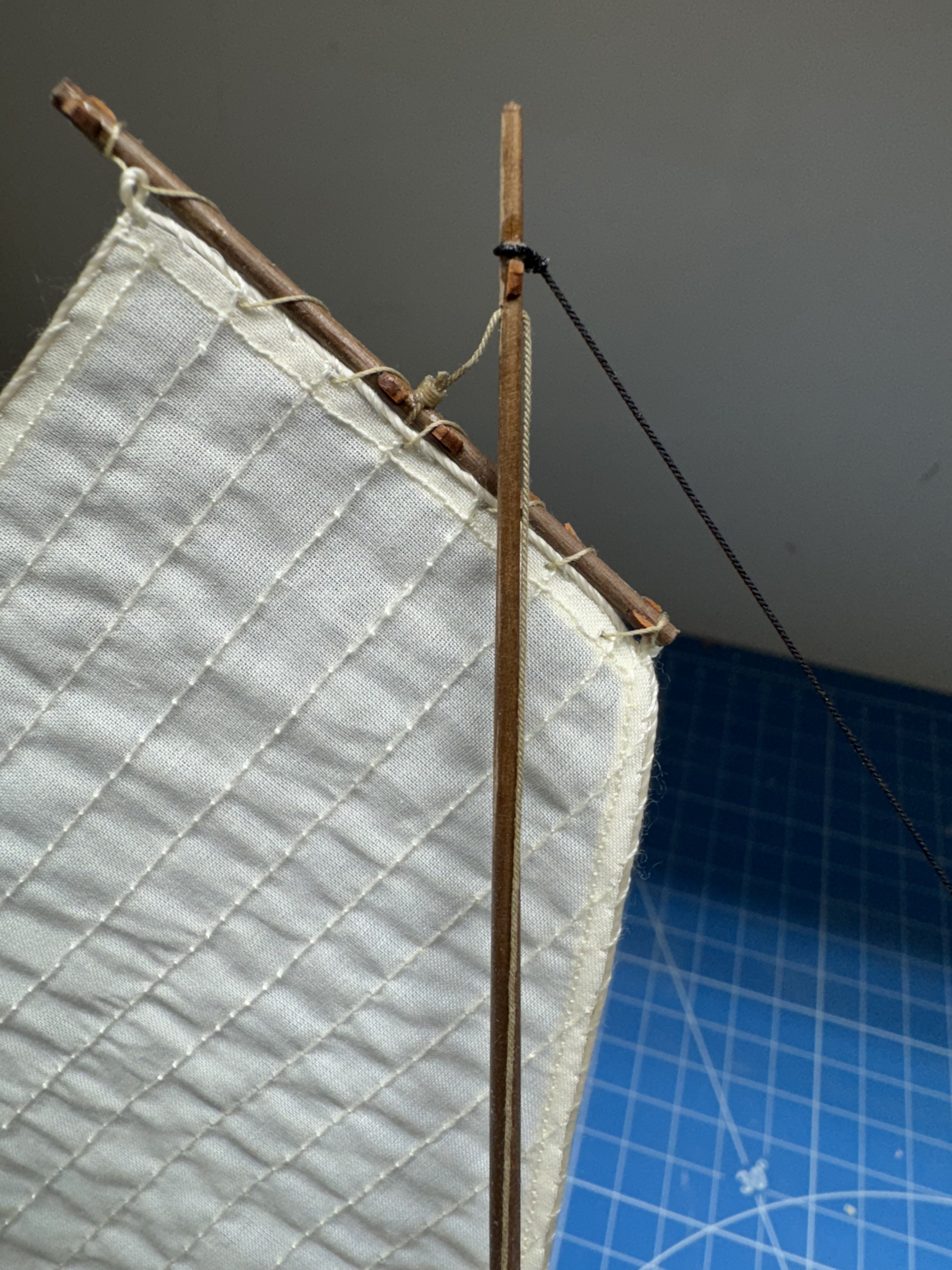
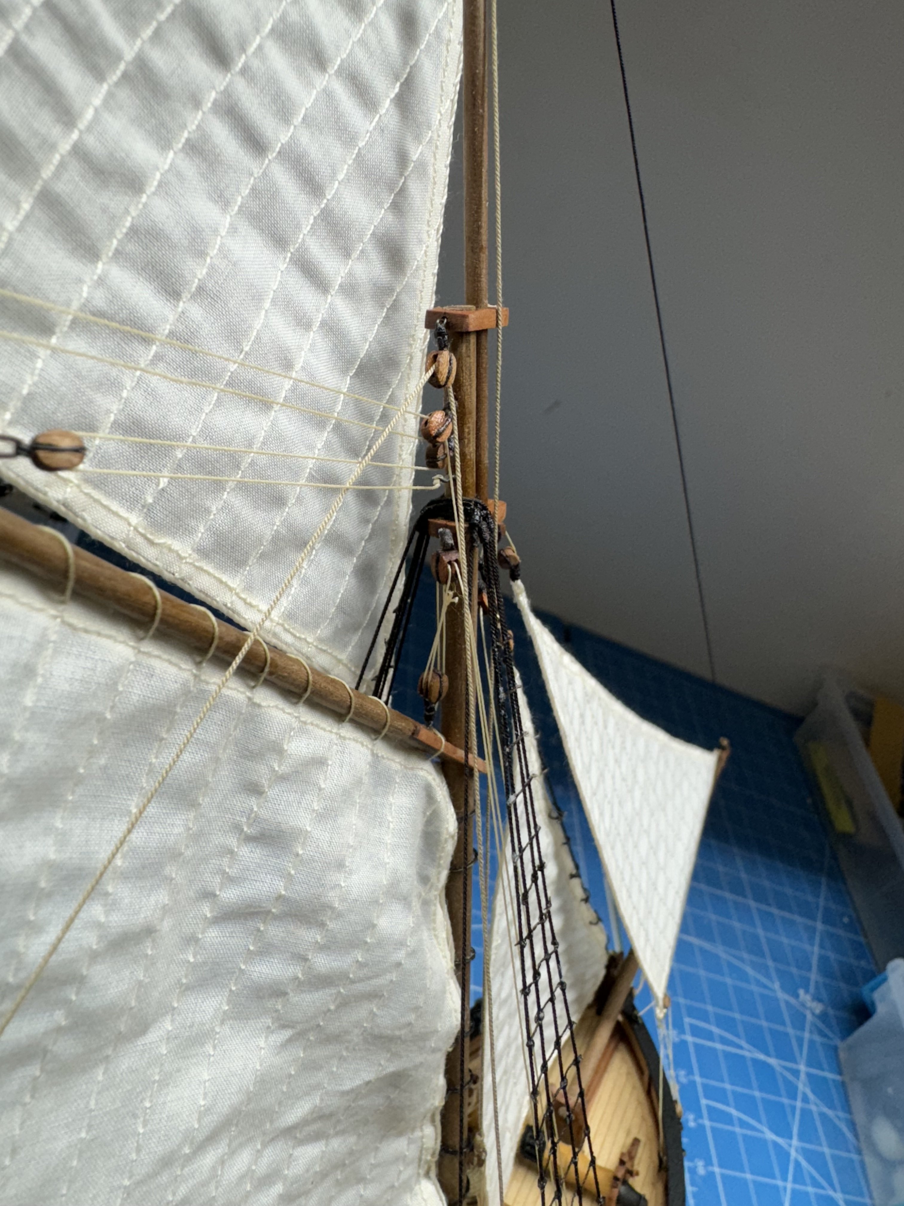
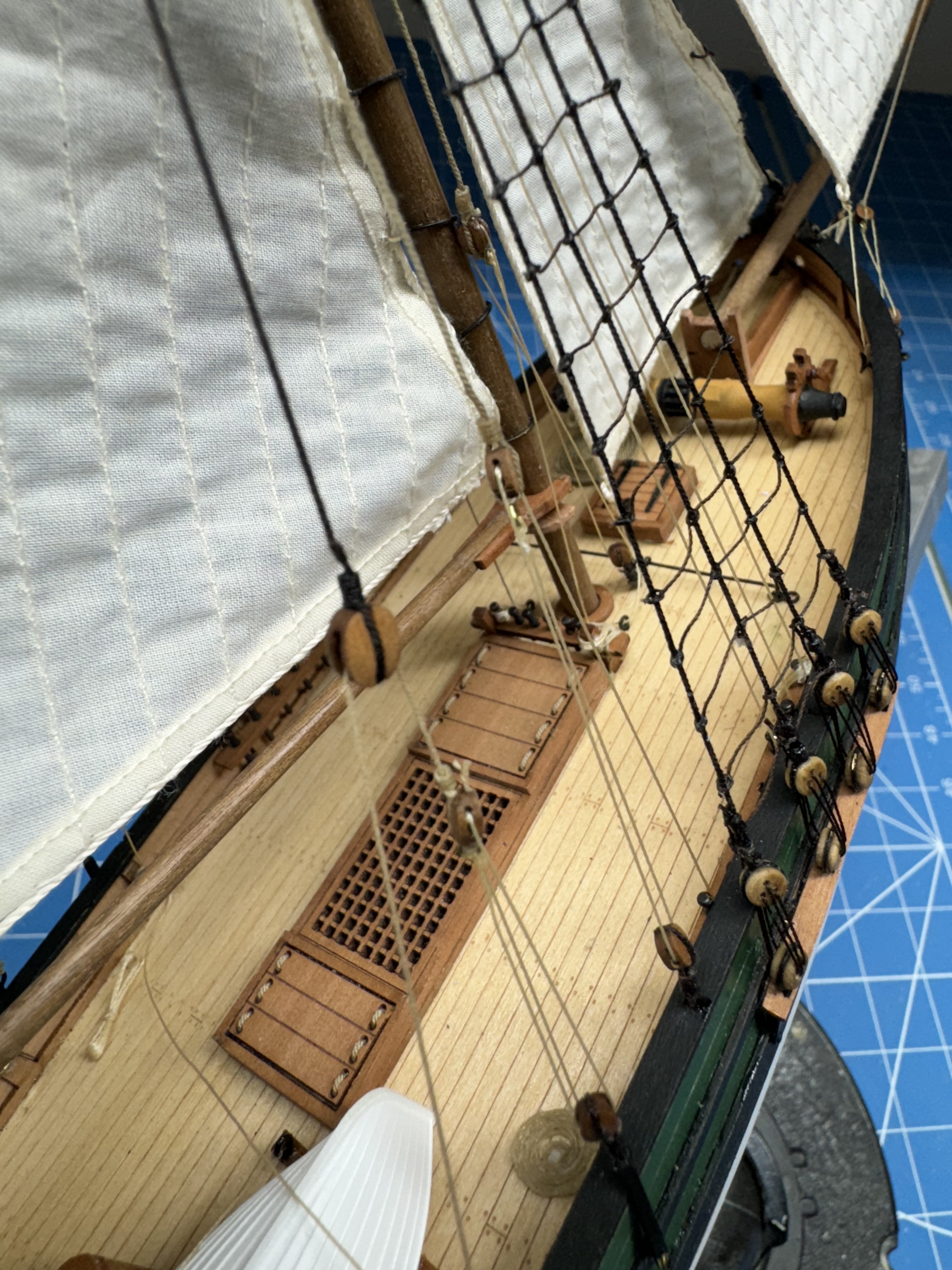
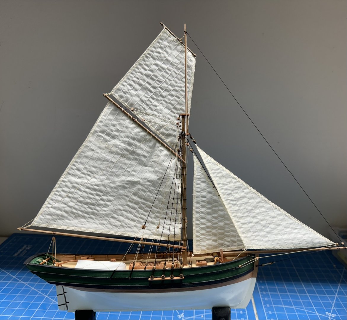
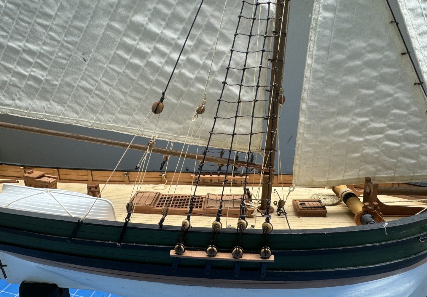
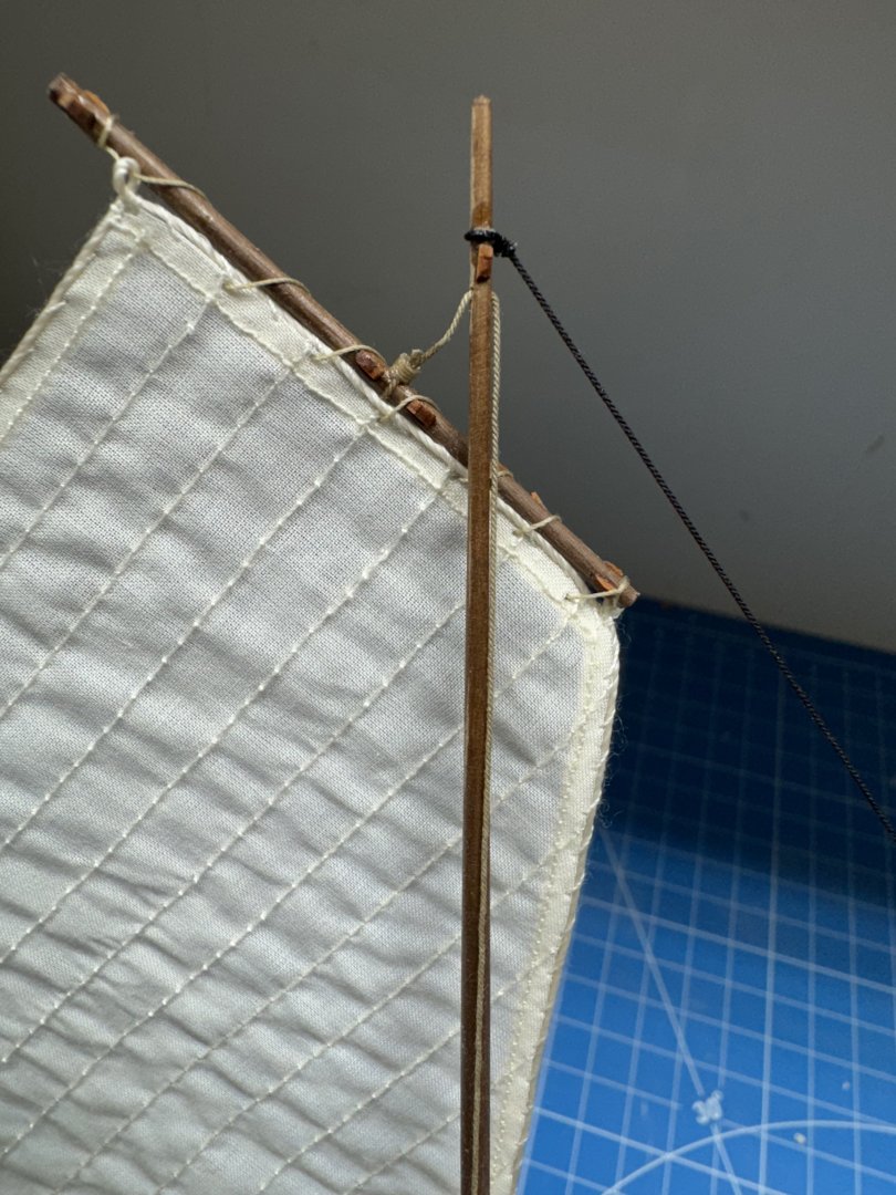
Here is the bowsprit and associated rigging. Mast head with jib halyards and throat and peak halyards. (I twisted the upper throat block some to get it to line up better with the lower after i saw this picture) The top mast with top sail yard. And a view down the starboard side looking forward. I have a few more rope coils to make and when I get them installed and do a little touch-up painting (and take the rest of the blue tape off) I will be ready to build the clear display stand and "put it on the shelf".


- 42 replies
-
- 5
-
-
- Saucy Jack
- Vanguard Models
- (and 1 more)
-
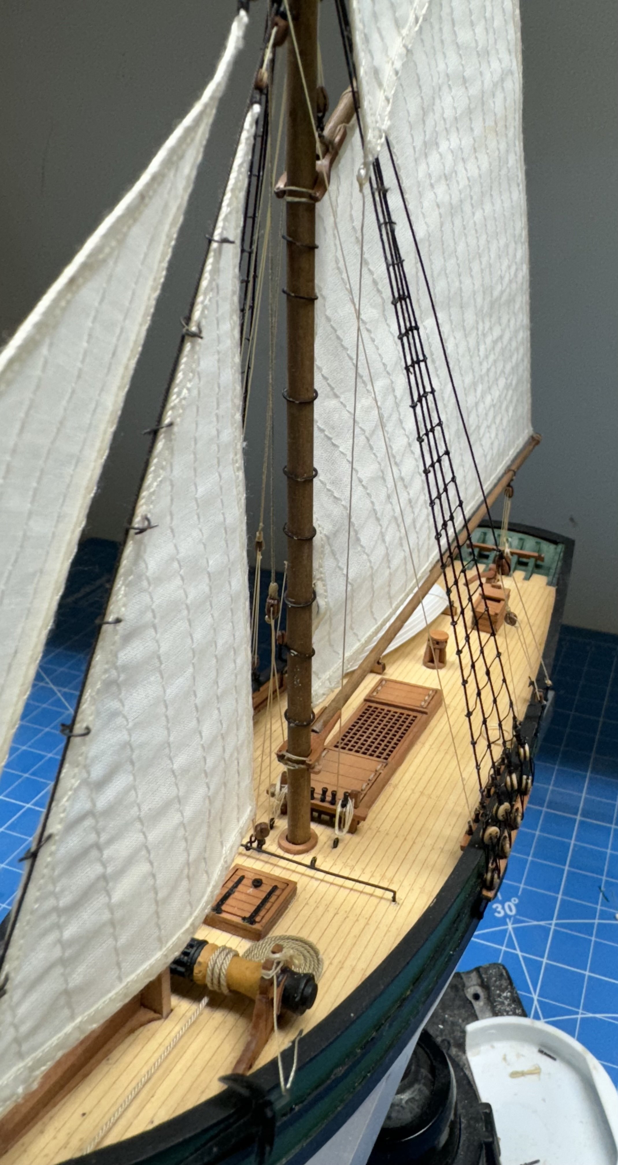
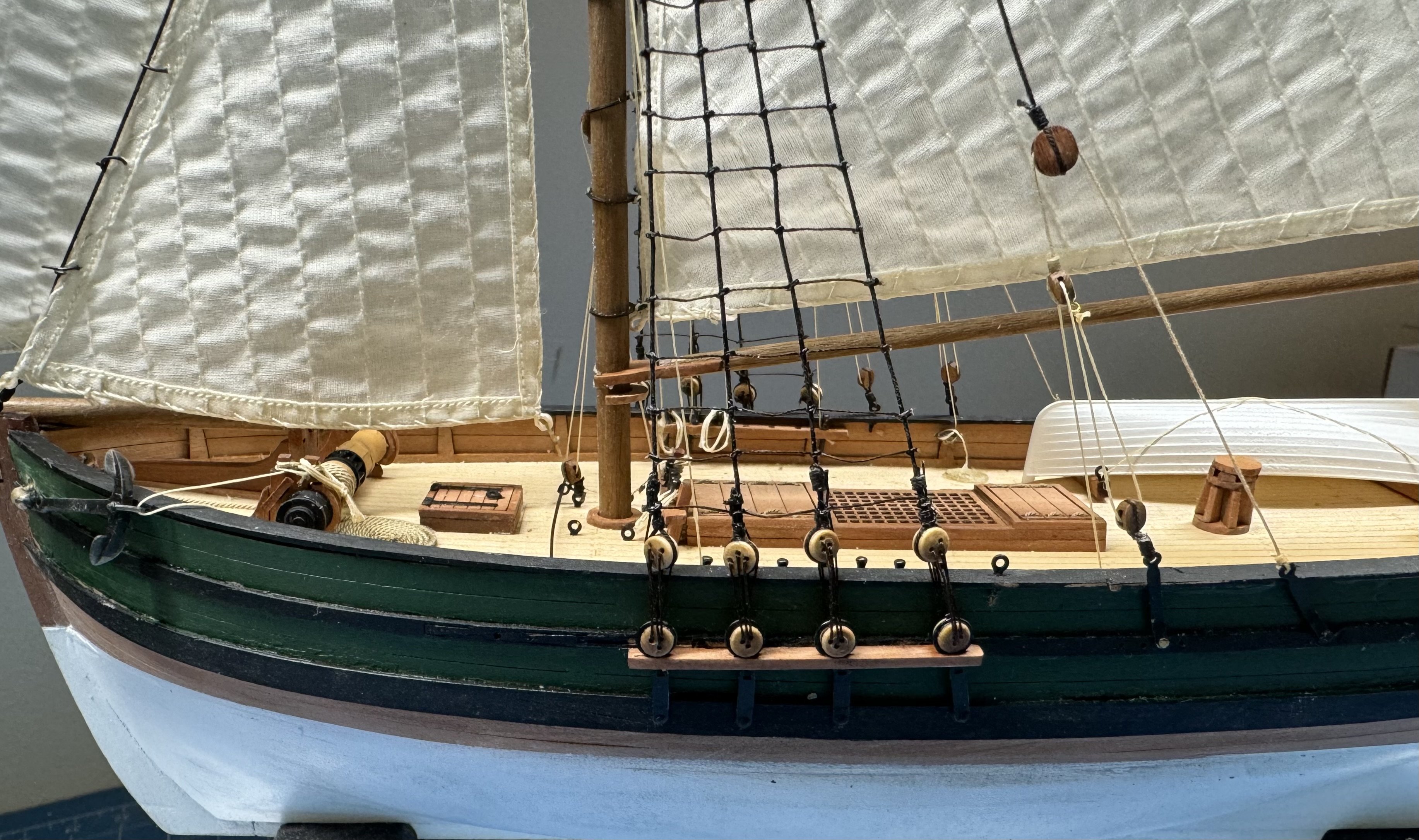
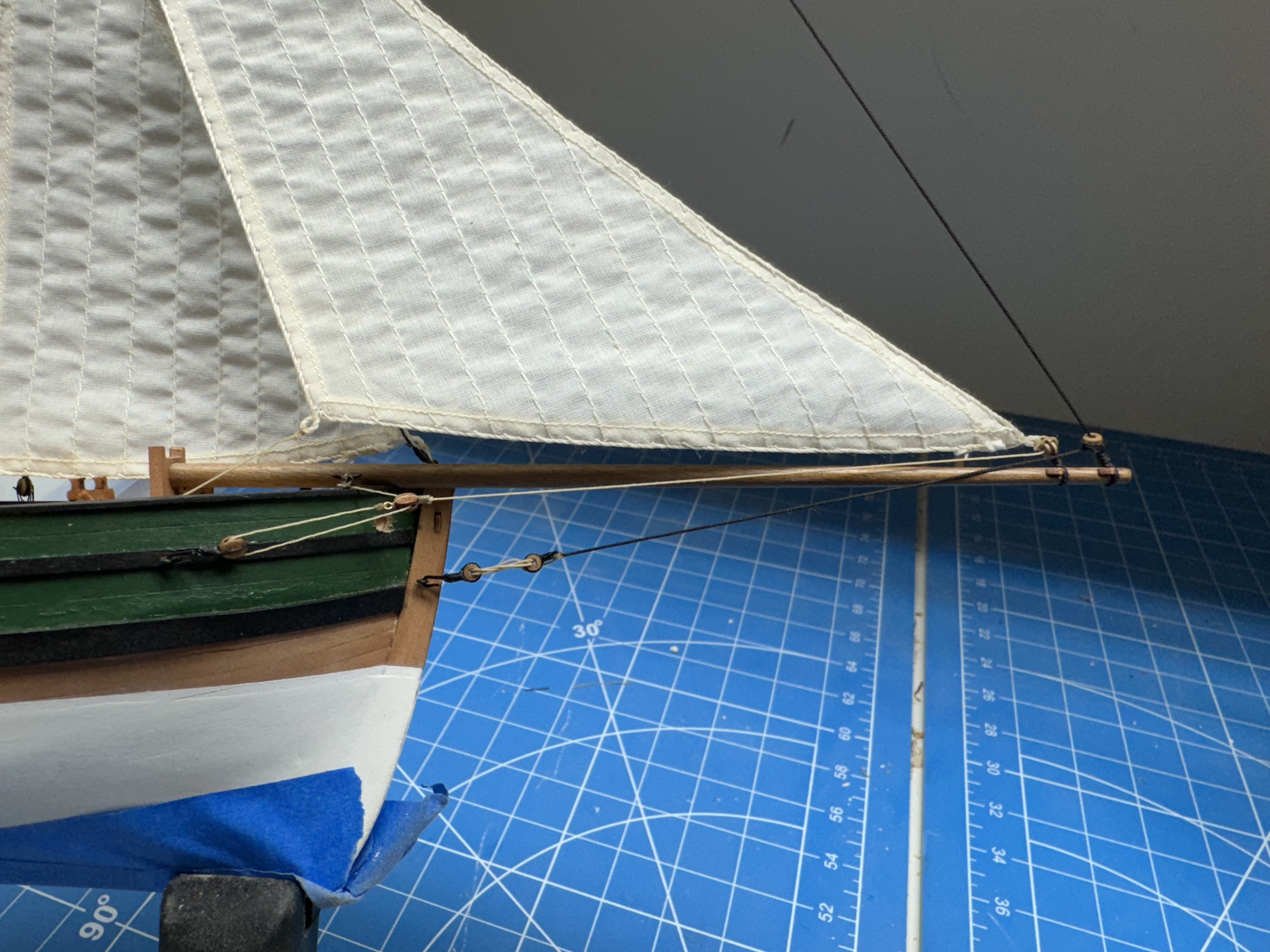
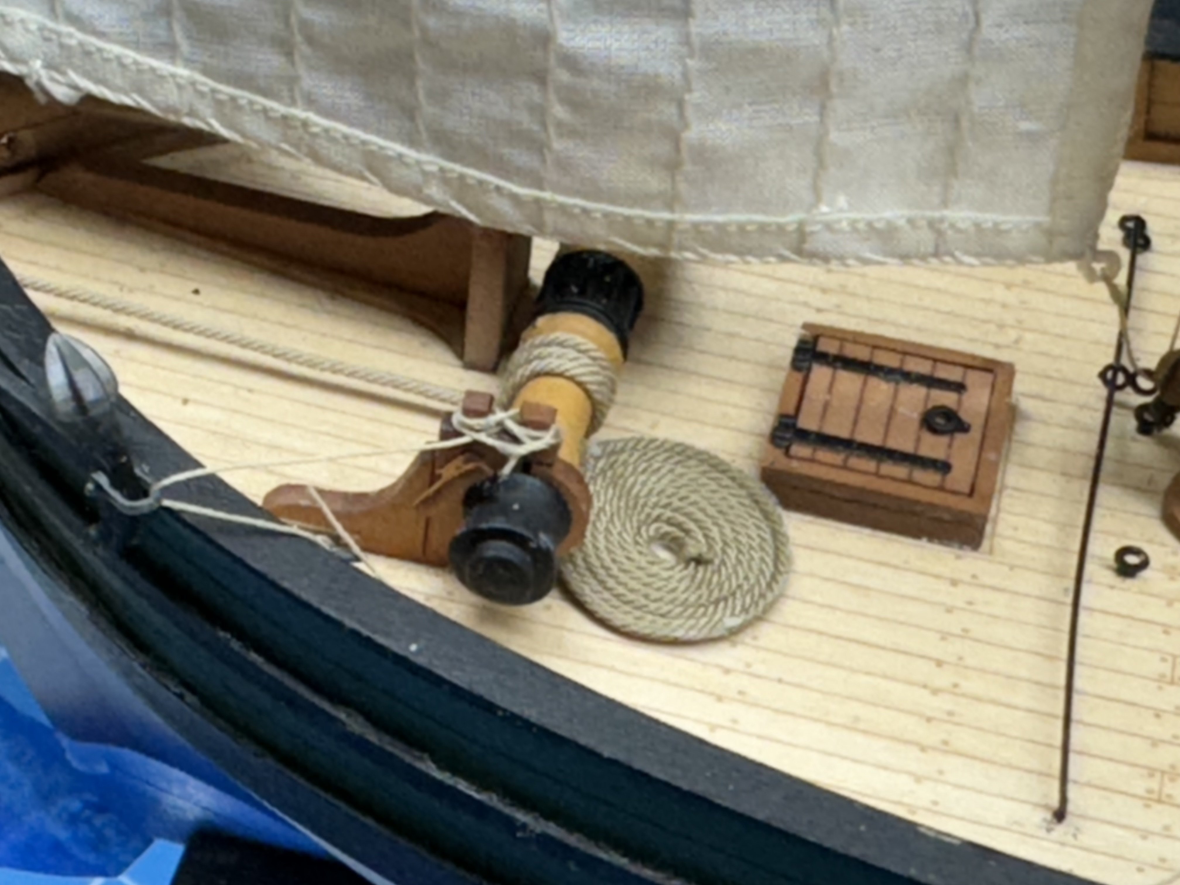
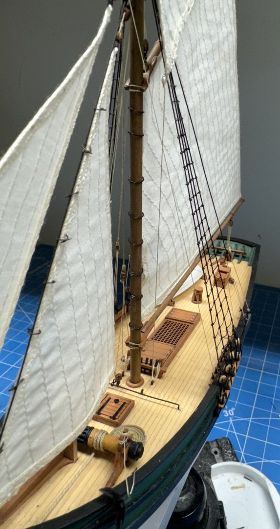
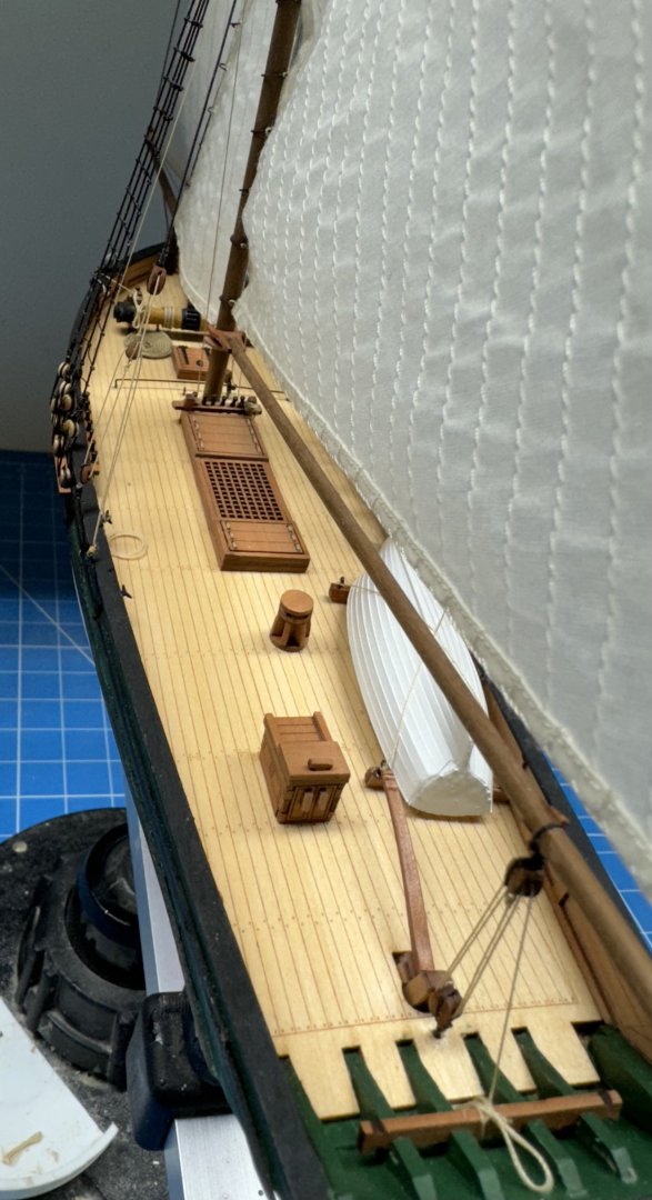
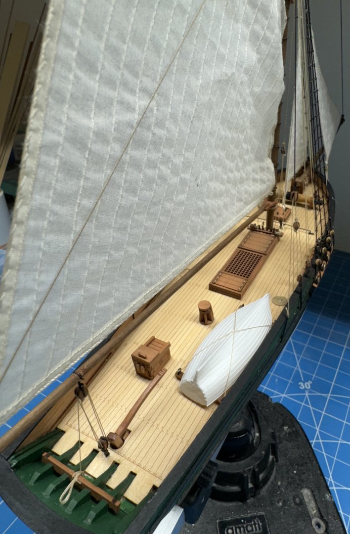
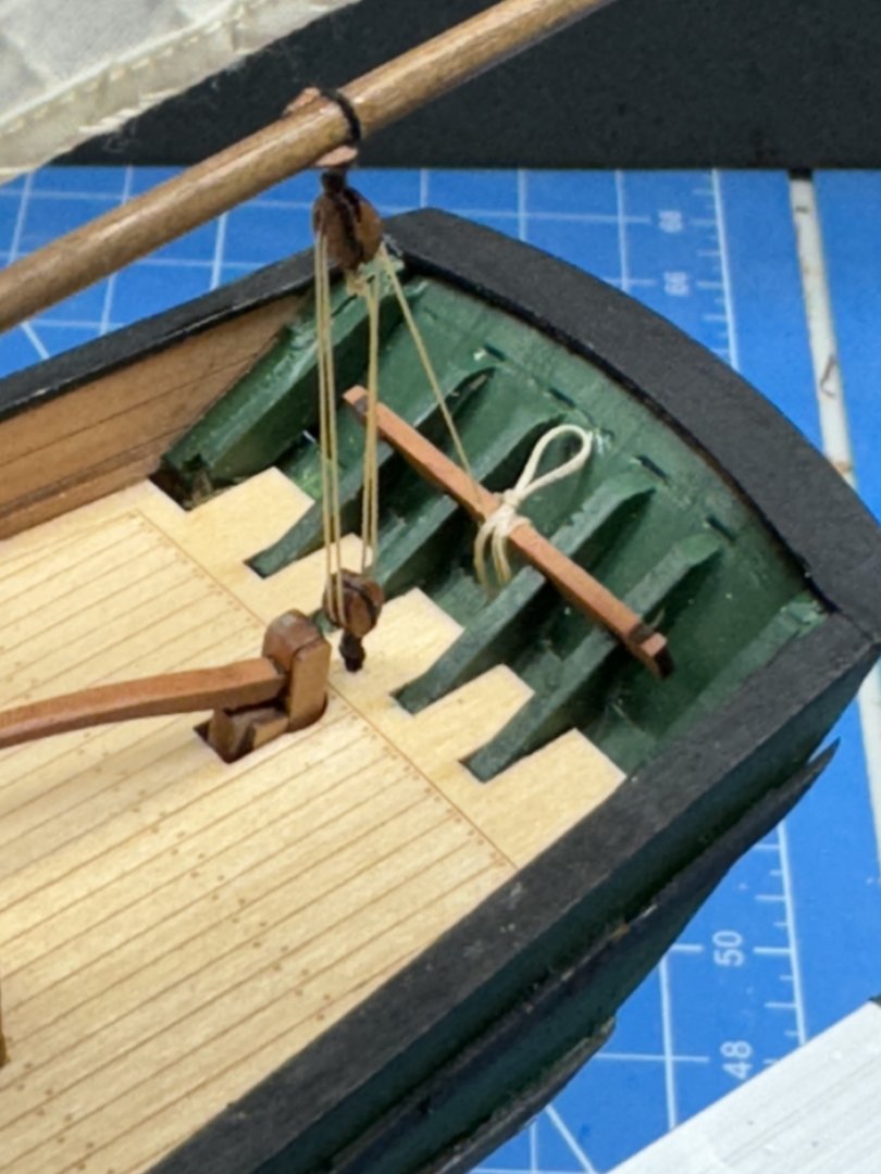
Thanks Dfell - here are some more pictures. I am still "running around" securing the running rigging and adding some coils of line in places. I had to rebuild my line coil jigs because everything I have is too big. Here is the main sheet tackle (with the tiller finally added). I decided to show the boat stowed on deck so I built a little "cradle" and tied the boat to it. At the moment it is just sitting on deck (no glue) as I am not sure where it should go. I think it has to go aft as with the cradle it doesn't really fit along side the fish hatches. I also decided to house the anchor and provide some rode on deck. I assume these boats did not carry a great deal of anchor rode as they probably only anchored in fairly shallow water - like to spend the night rather than go in with a bad catch. Not the most seaman like securing of the lines but getting that polyester line to act the way you need it to is a challenge.


- 42 replies
-
- 3
-
-
- Saucy Jack
- Vanguard Models
- (and 1 more)
-
Saucy jack is almost done. The clamps hanging down are holding some of the lines that have yet to be secured. Getting the line around the cleats and belaying pins is not that easy and manipulating to follow the examples on the drawings is impossible (for me). I am going to make up some coils of rope to hide the mess around the cleats/pins but that may take a bit of time as I have no experience creating them using 100% polyester line. I wonder jsut how much "extra" line they would have laying around on a commercial fishing boat - I would expect not what you would see on a man-of-war but... I also have some paint touch-up to do but will wait until I have the lines secured.
- 42 replies
-
- 5
-
-
-
- Saucy Jack
- Vanguard Models
- (and 1 more)
-
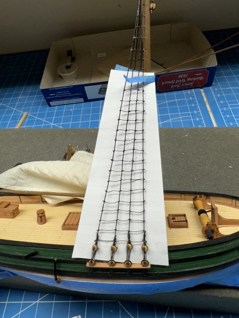
Starboard side ratlines complete. Not the neatest job I every did and I think I might have gone with the .008 Syren line given the above info. When I got to the top three or four rows, where the shrouds are very close together I put a drop of PVA/H20 on each shroud and coaxed a short length of the polyester across the shrouds in a more or less horizontal line. When the glue dried I put a drop of thin CA on the part sticking out on each side to (hopefully) stiffen the polyester and make cutting it off easier. Seemed to work okay but on port side I am going to try "Tacky Glue" instead of the PVA/H2O for the upper ratlines. I may start at the top and see how far down it looks reasonable without an obvious "knot" at the junction.
- 42 replies
-
- 1
-
-
- Saucy Jack
- Vanguard Models
- (and 1 more)
-
Thanks Jacques - if you are retired and have nothing better to do (it is really hot here in Florida at the moment) then working on your ship model(s) is what you do. I have done some research and a source on MSW quotes Lee's Masts and Rigging of English Warships (I have a copy coming from eBay) that ratlines were 1.5" circumference no matter the ship size. That would seem to stand the idiot test since the object of the ratlines is to get the sailors up and down the masts. And sailors are pretty much a common size there should be a "best" size for the things they step on to get up and down the mast no matter the size of the ship. 1.5" circumference works out to .477" (divide by pi if I remember my geometry correctly) which at 1/64th scale would be 0.0075" 0r 0.1898mm. Assuming the above reference is correct (and I have no reason to doubt it) then using .008" line would be "okay" for an English warship like Sphinx. Maybe not so much for a small fishing boat like Saucy Jack.
- 42 replies
-
- 1
-
-
- Saucy Jack
- Vanguard Models
- (and 1 more)
-
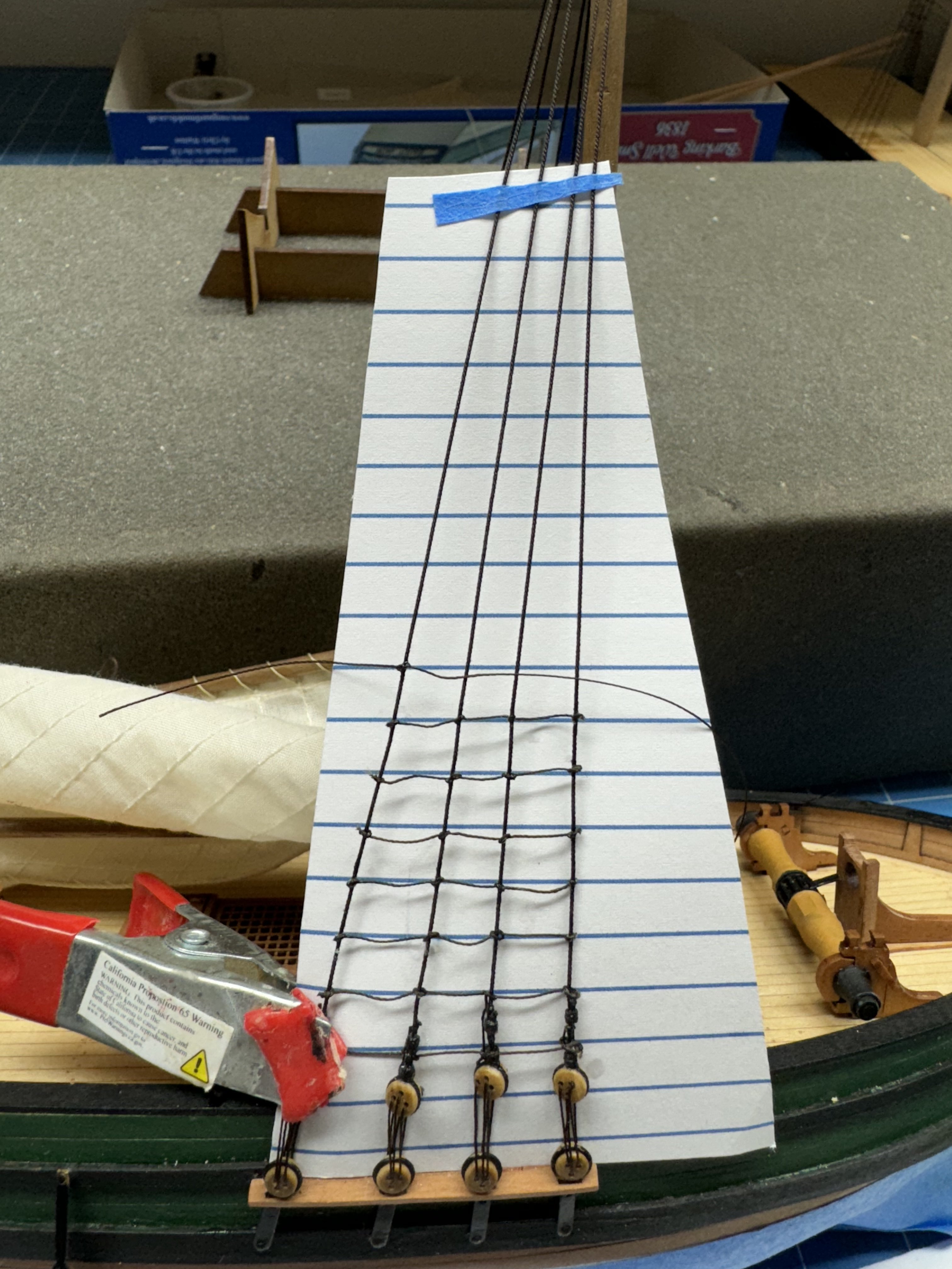
While "playing" with the polyester thread (line?) I noticed that it has some twist "built in (as does any thread made from twisting smaller fibers together). This twist made the line want to go in a direction different from what was desired on what seemed like many occasions. I worked out that a length on about 200mm was the "best" (for me) which is long enough to have plenty of "extra" line to grab a hold of but not so long as to get caught on everything around. So I cut several lengths and hung them mover the workbench edge to see if at least some of the twist would work itself out. I am not sure things are any better but I feel better so that is what counts. Anyway I am about half way up the starboard shrouds. I decided to use overhand knots as I know how to tie them without consulting the drawing every time and I think the leave less of a "bump" at the junction with the shroud. I also am using thin CA to "fix" the knots as it is faster and it stiffens the thread which makes it easier to trim off the excess. I probably should have consulted the drawing after I made my spacing template as I am going to have several more ratlines than is shown on the drawing. I guess I better redo the template if I intend on using it on Sphinx.

- 42 replies
-
- 2
-
-
- Saucy Jack
- Vanguard Models
- (and 1 more)
-
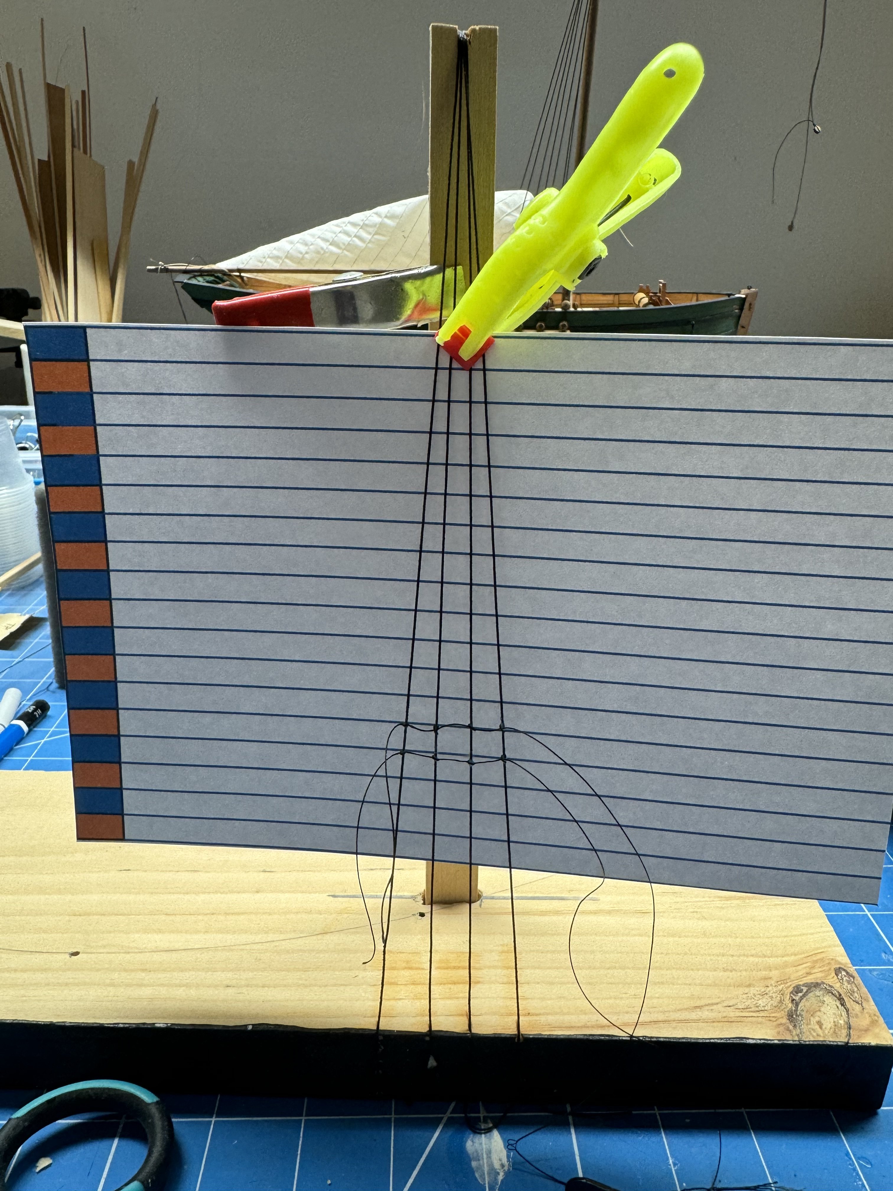
Starboard side completed and all the deadeye lanyards have been glued down. Time for ratlines. Because it has been a few years since I had to "do" ratlines I decided that maybe a little practice was in order. So I built a little "replica" of the SJ shroud configuration and tried a few "practice" ratlines using the polyester line referenced above. I used PowerPoint to create the ratline template and saved the file as I suspect the spacing will be very similar on other 1/64th scale models. I did two rows but had to look at the drawing provided of how to tie a clove hitch at least ever time i had to tie one, sometimes more than once per. Anyway I dabbed each junction with 60/40 PVA/H2O and it is drying now. Will trim the ends when it dries and see how it looks. Seems to be going okay with the poly line but the PVA needs to hold the knot or it is game over.

- 42 replies
-
- 1
-
-
- Saucy Jack
- Vanguard Models
- (and 1 more)
-
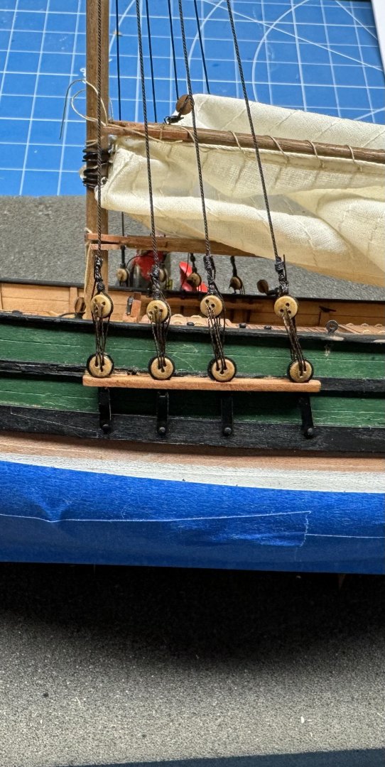
Port side deadeye lanyards completed. The deadeyes could be a little closer to the same height but since they are in pairs if you move one up the other moves down so.... And I managed to scratch up the sides behind the channels reaching with the tweezers to grab the line coming through from outboard. Maybe I will try and get back there with a small brush - and maybe not. The lanyards look a little "thin" to my eye but I think the Guttermann Tera 60 I used is slightly larger than the Guttermann CA02776 that comes with Sphinx and I assume it is the same material on Saucy Jack although it does not come identified my manufacturer in the SJ kit. Also another hit on the polyester lanyards is they seem to have less ability to resist the twist in the shroud line and thus the deadeyes appear even more out of alignment. On a larger ship there is a wooden batten that runs across the shrouds just above the deadeyes (which I am sure has a particular name but...) that helps to correct the deadeye alignment but not on Saucy Jack (although adding one would not be terribly difficult). Admittedly what I have used before for lanyards (Syren .008") is considerably thicker but at 1/64th has not seemed totally out of scale on other models although that is a pretty small sample size - at least for me. I have built only two other models with this deadeye/shroud configuration, both 1/64th scale (Niagara and Pride of Baltimore) On to the starboard side to finish up and then my favorite - ratlines .🙁.
- 42 replies
-
- 3
-
-
- Saucy Jack
- Vanguard Models
- (and 1 more)