NRG Photographic Model Ship Competition - All eligible to enter - Reduced memberhsip fee - JULY 31 ENTRY DEADLINE
×
New Banner Ad Sponsor - Epic Engravers - Great plank bending machine (also bends thin metal sheets) and unique engraved coins to label your model displays!
×


cdrusn89
-
Posts
1,915 -
Joined
-
Last visited
Content Type
Profiles
Forums
Gallery
Events
Everything posted by cdrusn89
-
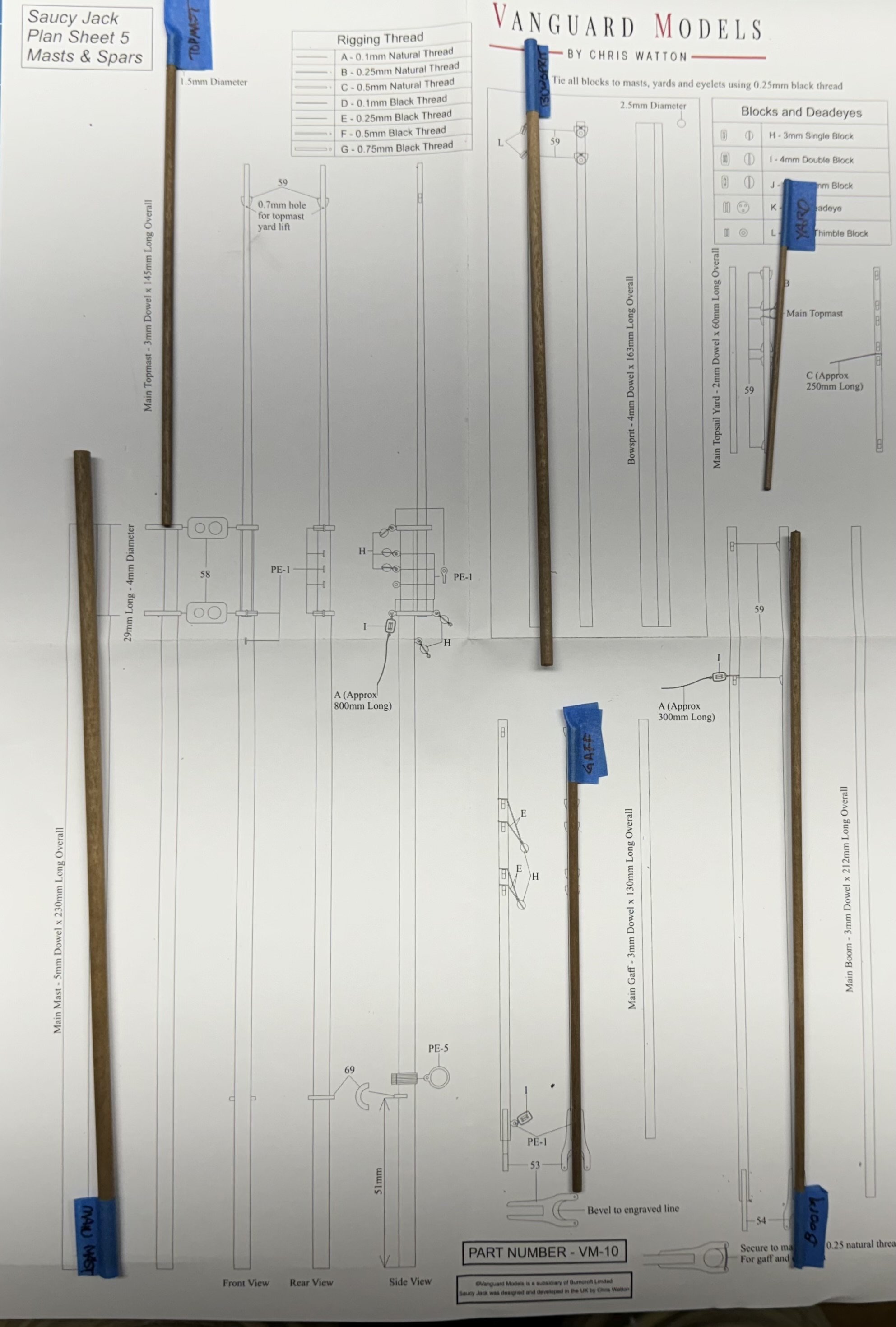
 Main and top mast completed just need to add the line to the double block on the aft side of the lower mast cap - it will be the throat halyard for the gaff. The two pieces are not yet glued together. Too much opportunity for damage with long, thin "things". Working the other spars and the hull is in the paint booth for its first coat of primer + filler. Will let that dry overnight and the prepare for the second "try". The replacement HMS Sphinx kit looks to be here on Thursday so I need to keep pressing on the Saucy Jack. I would like to get it to the stage where I can work on it a little at a time while I rebuild the Sphinx hull.
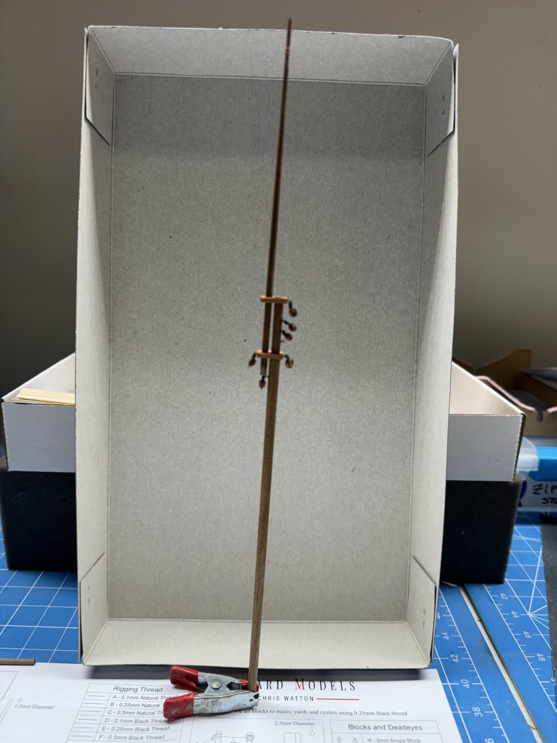
-
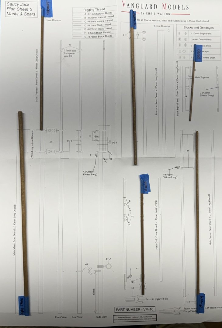
With filler on the port side of the hull drying I turn my attention to the spars. Six spars but only three (bowsprit,main and topmast) need tapering. I am not crazy about the dark colored wood but since they are all the same and since making relatively long thin spars out of rectangular stock can get pretty tricky I will use these. Also - no painting so one less thing to accomplish.
- 42 replies
-
- 1
-

-
- Saucy Jack
- Vanguard Models
- (and 1 more)
-
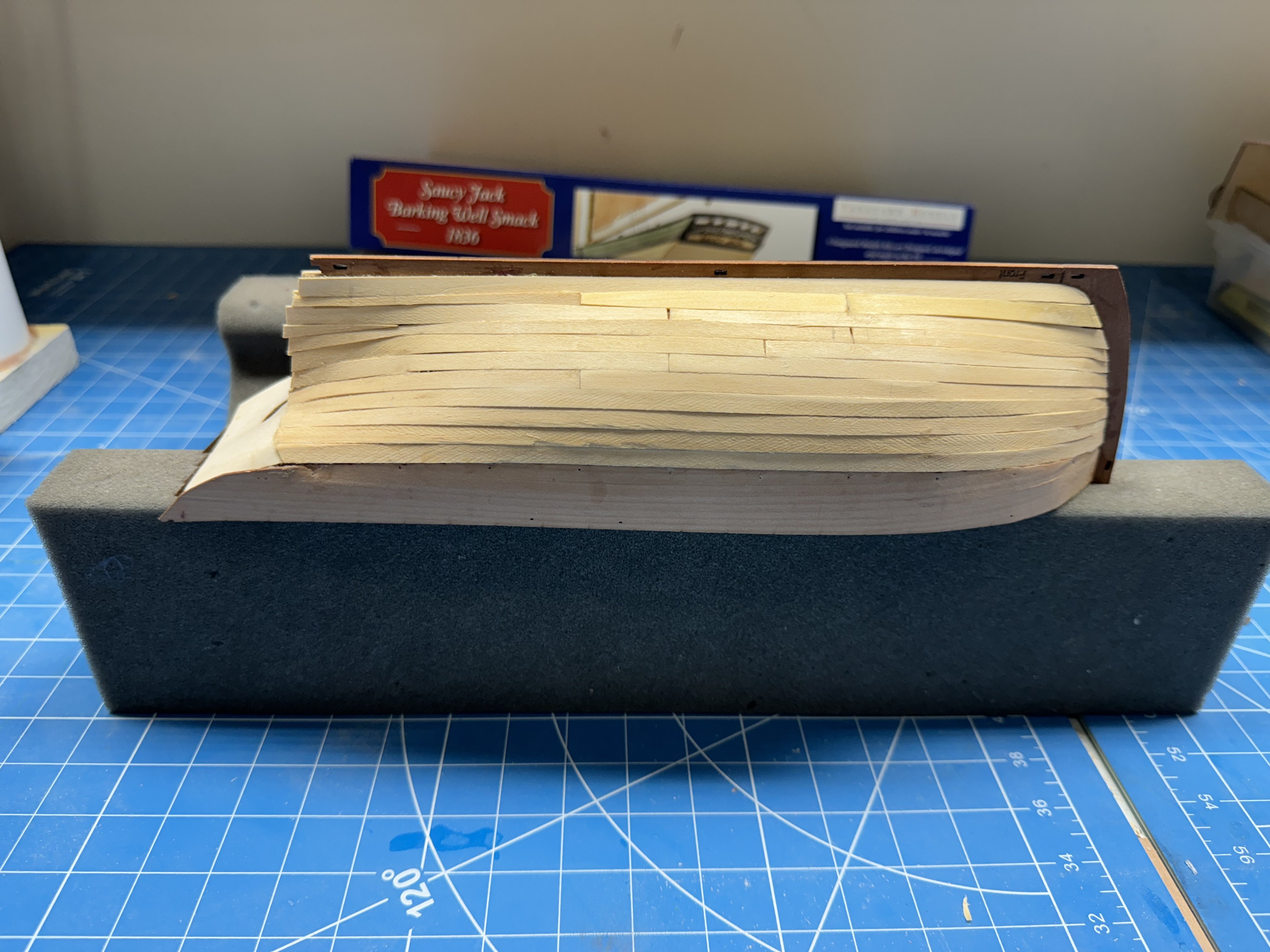
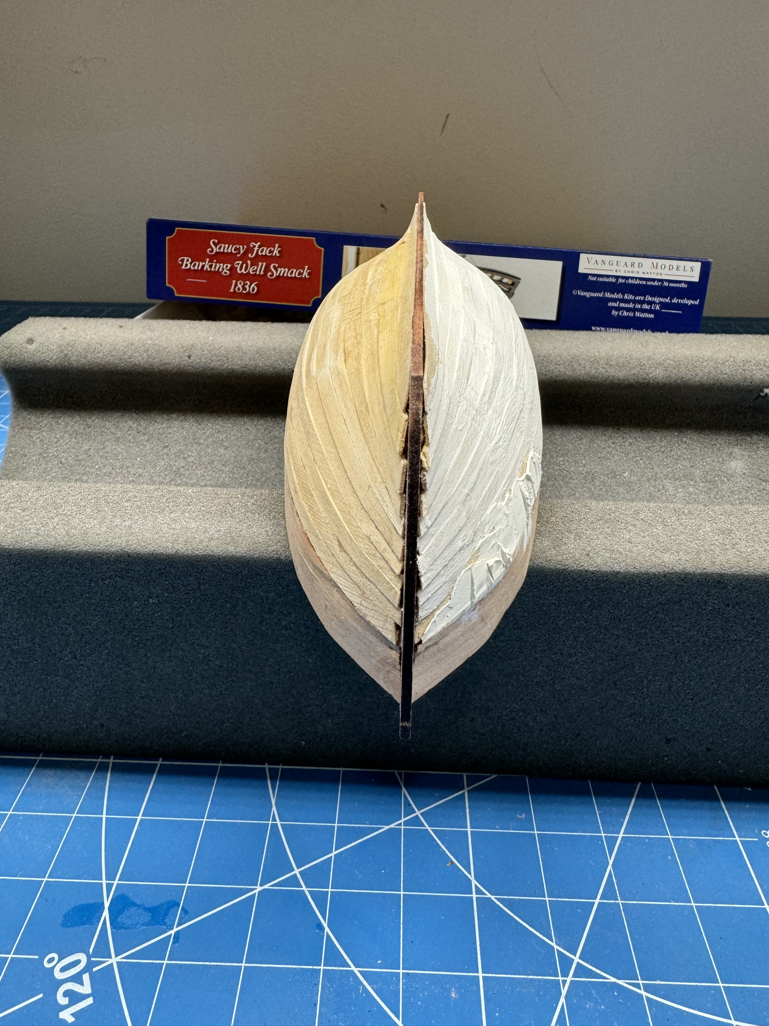
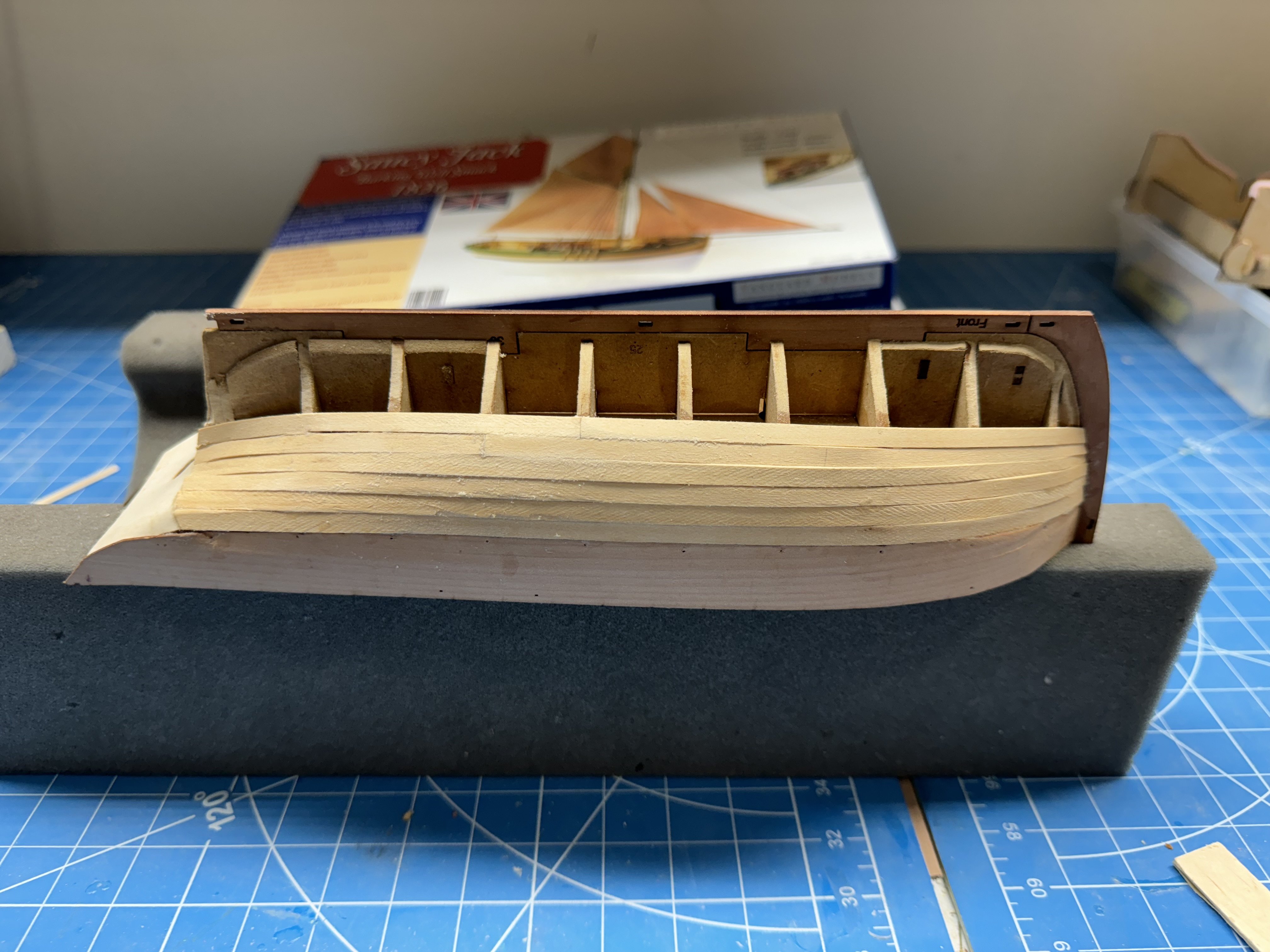
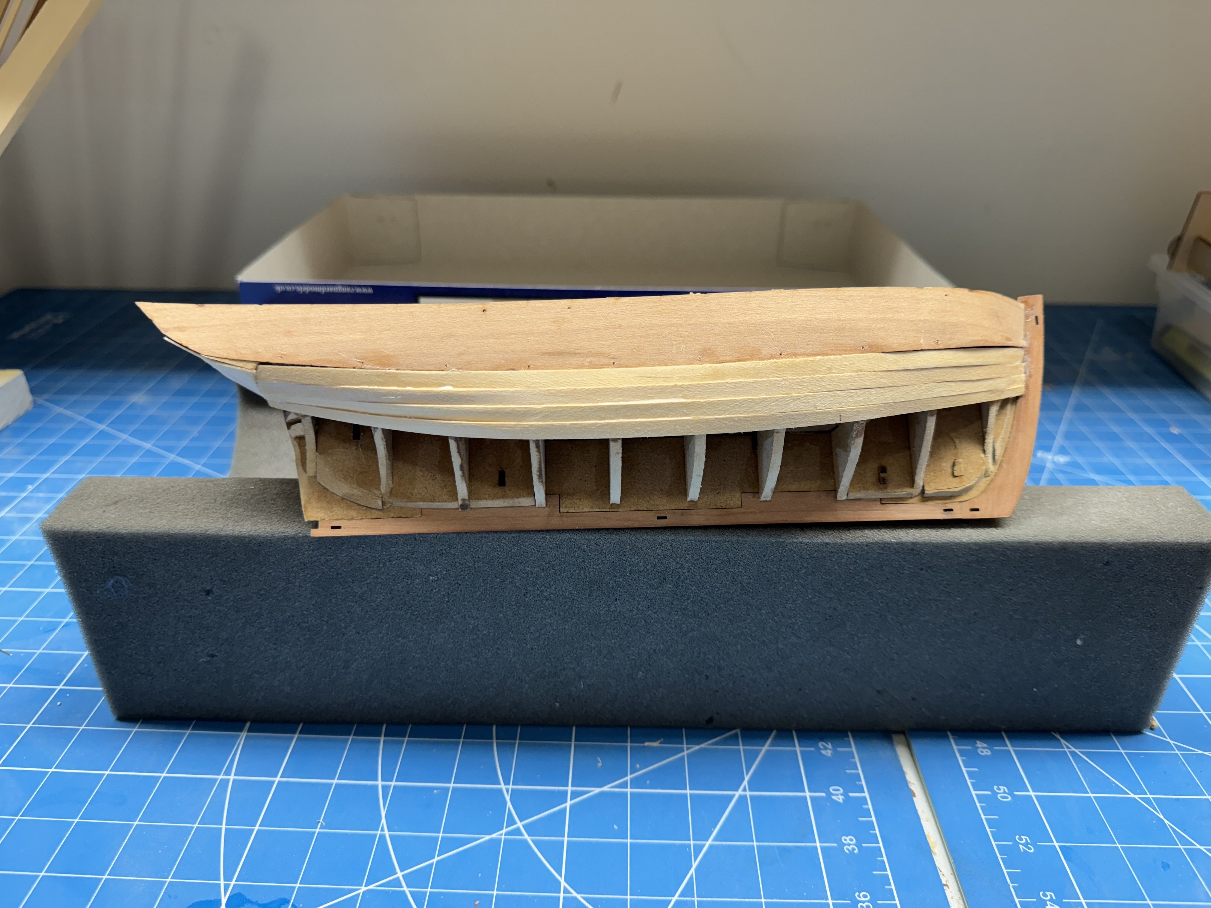
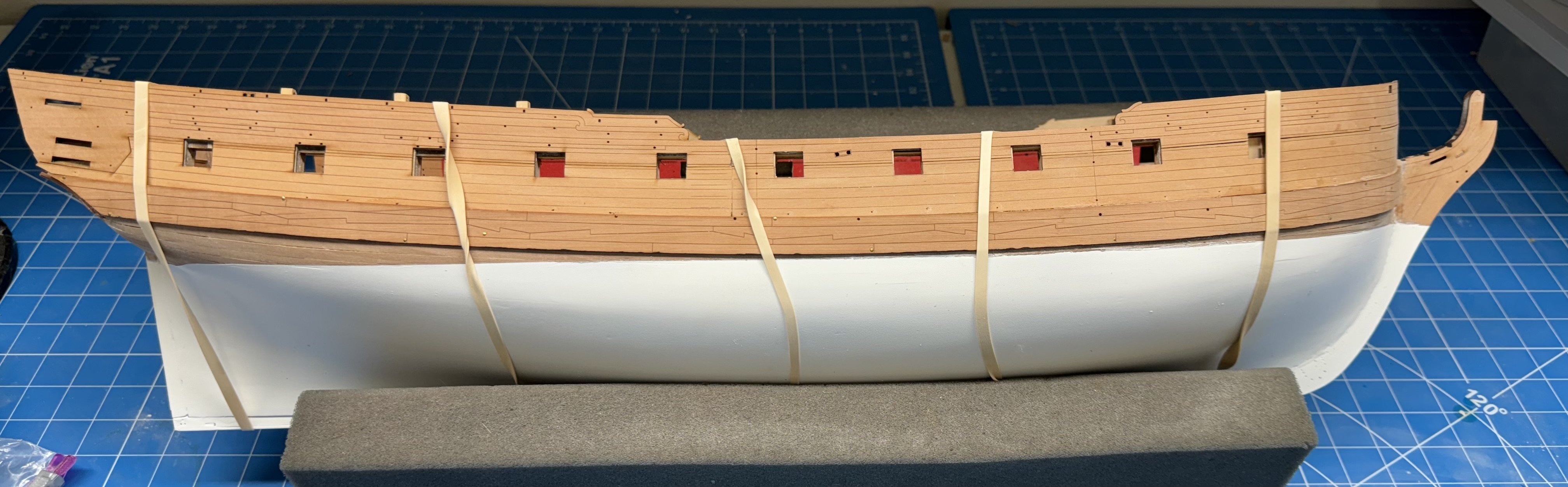
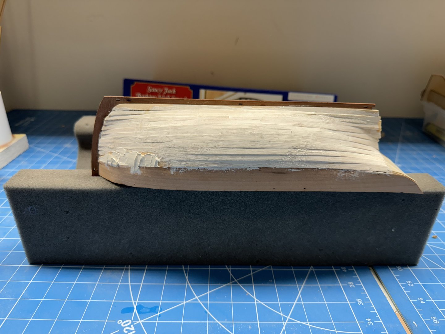
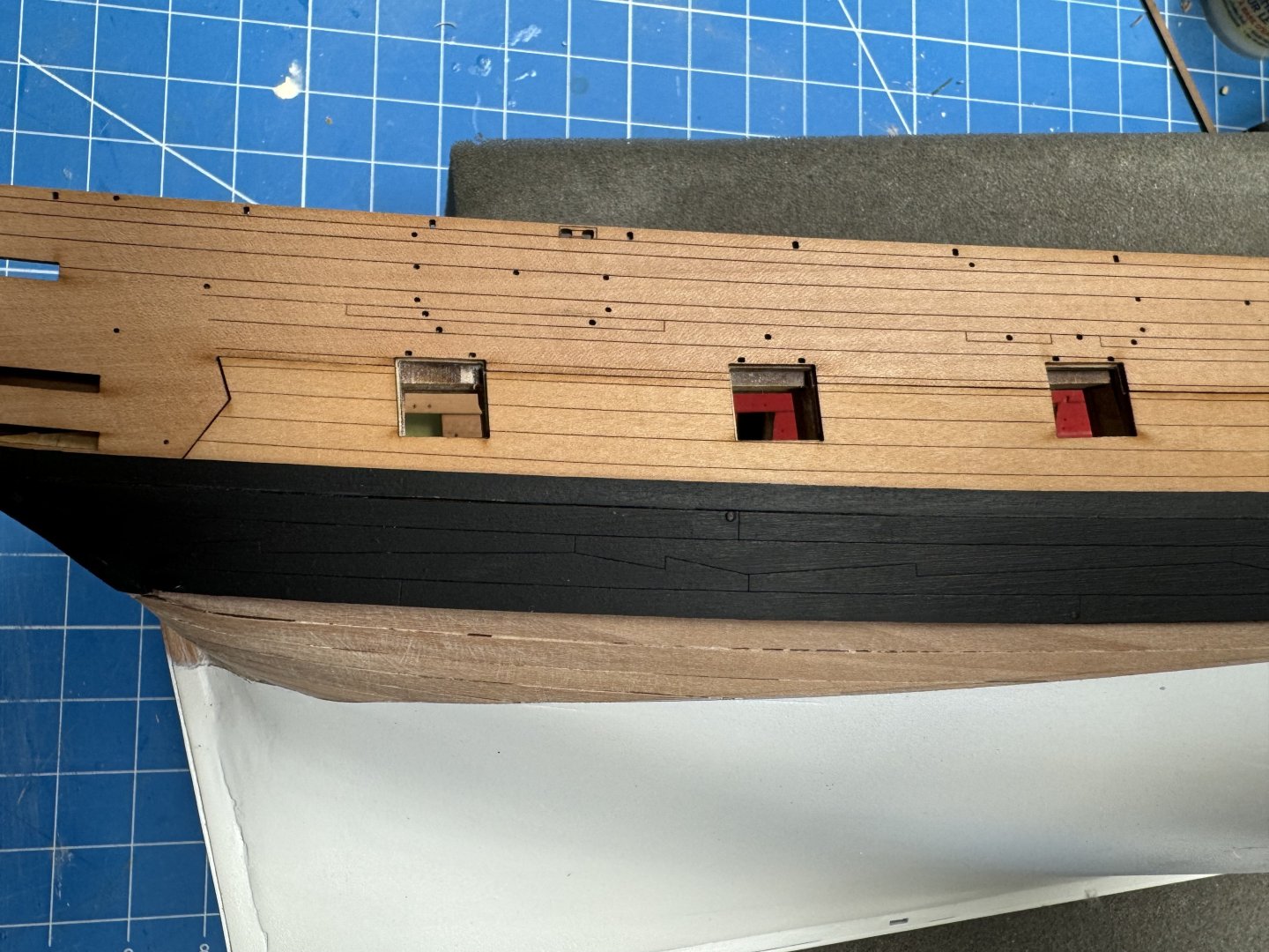
The first layer of planking is complete. The starboard side has the first "coat" of thinned filler applied and some of the filler "straight" (see below). The port side planking has the 50/50 PVA/H2O that was painted on the last few rows of planking drying. On the starboard side there was a significant discontinuity between the bulwark planking and the first row of planking near the bow. Clearly there was some problem with my fairing of the hull in that area. So I will attempt to fair the two areas together with filler so the second layer will not make a repeat performance. I will try and get this layer smooth using several courses of thinned filler, 220 grit sandpaper. and auto body spray paint with filler. That course of action worked (finally it seemed like a dozen courses but was actually significantly less) on the hull of HMS Sphinx.


- 42 replies
-
- 6
-
-
- Saucy Jack
- Vanguard Models
- (and 1 more)
-
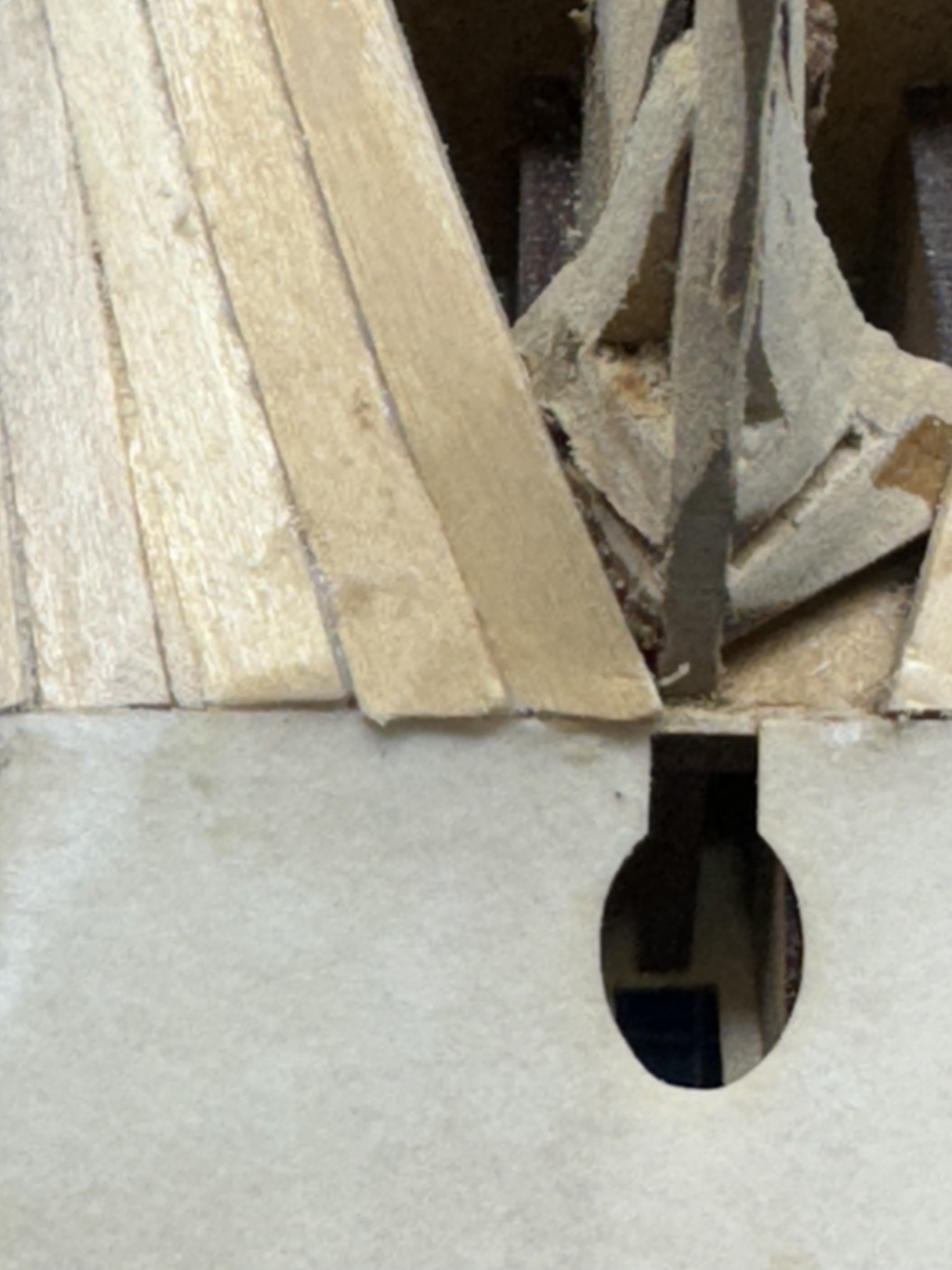
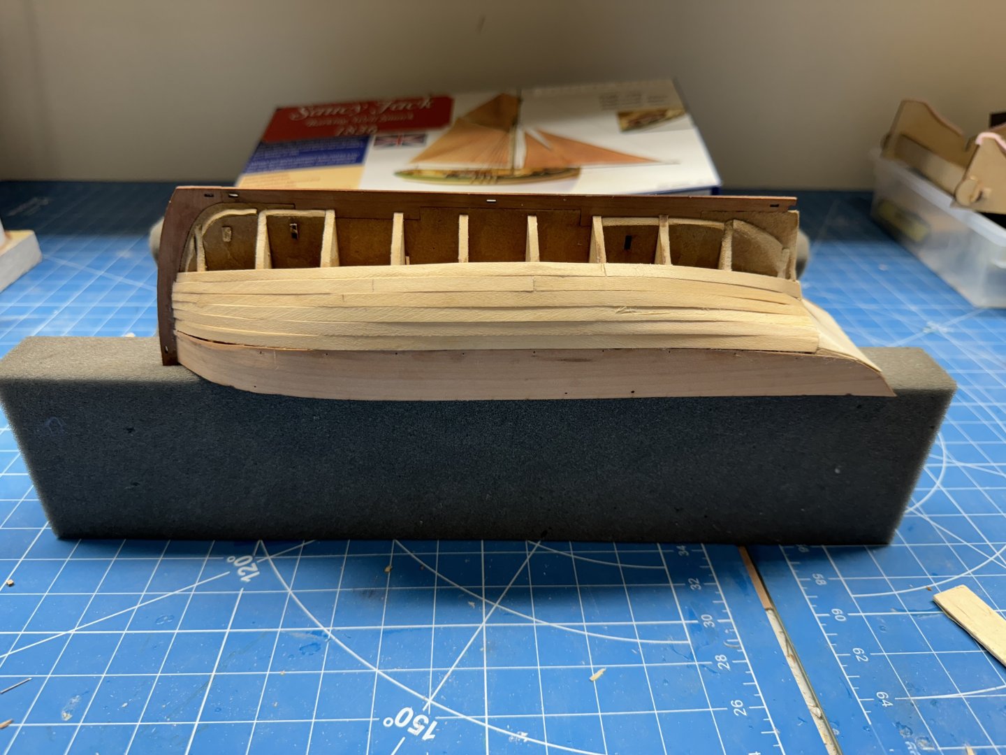
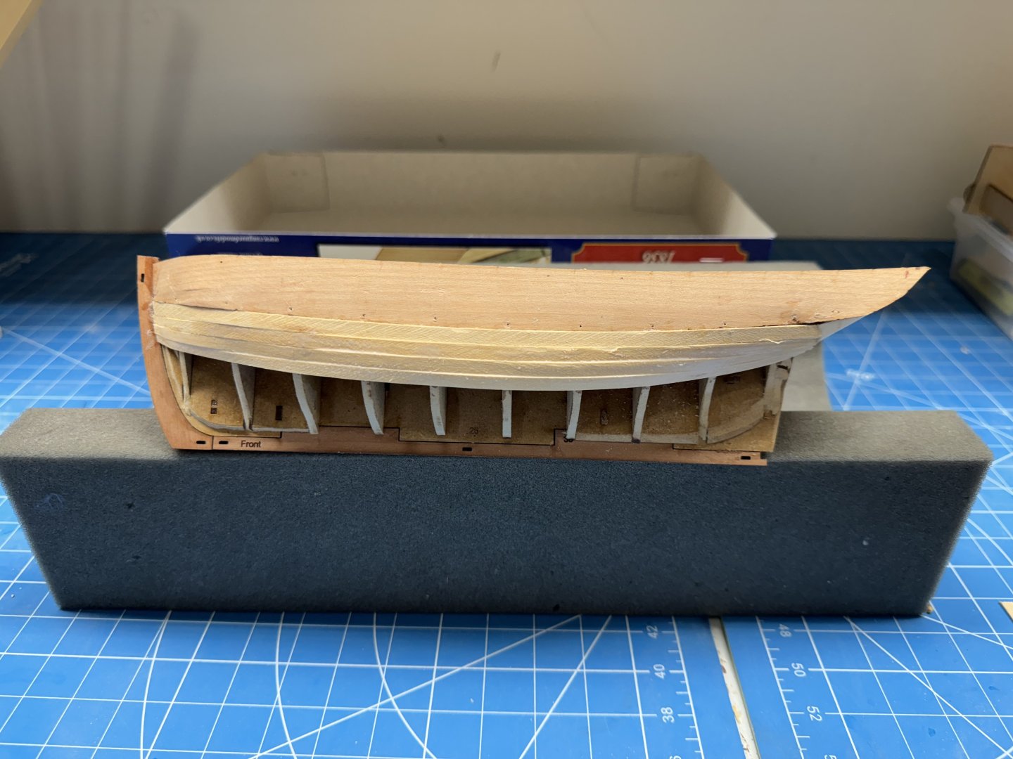
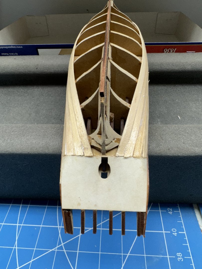
Six rows on each side. I used split planks for both rows five and six as making things"fit" at both ends is harder with a single plank. And there are no extra points for doing it the hard way. Successfully made the transition to the stern post. I had to add a little "sealer" to the starboard side. If I could just do this well planking Sphinx I would be a happy camper. Next is to add the garboard strake and then work from there back towards the sheer.


- 42 replies
-
- 1
-
-
- Saucy Jack
- Vanguard Models
- (and 1 more)
-
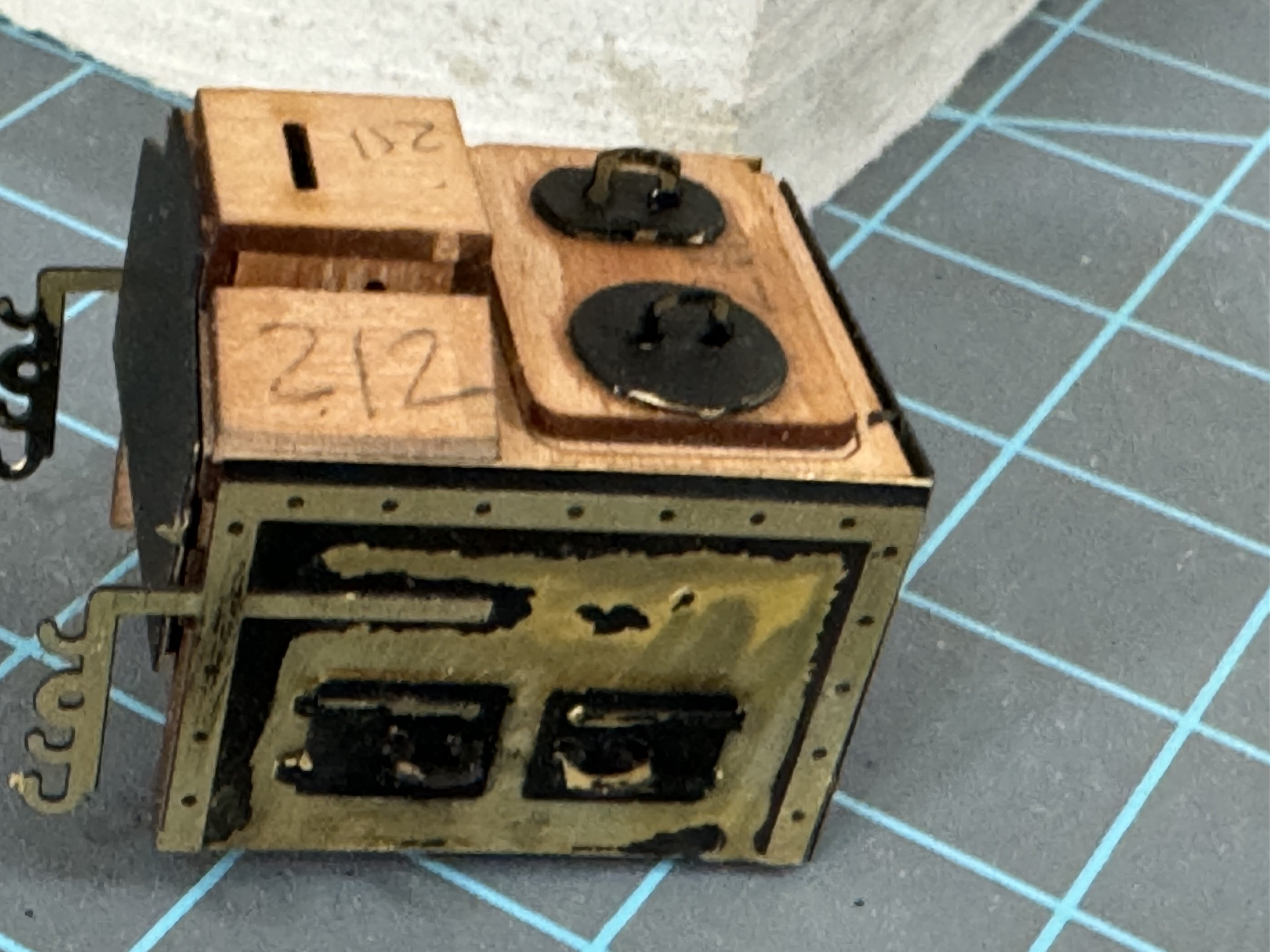
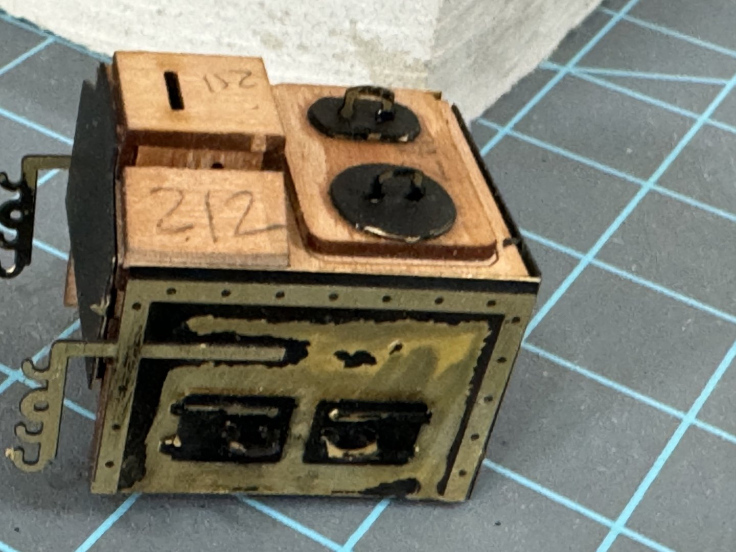
The stove joins the anchors in the "to be installed someday" box.
- 422 replies
-
- 5
-
-
- Vanguard Models
- Sphinx
- (and 1 more)
-
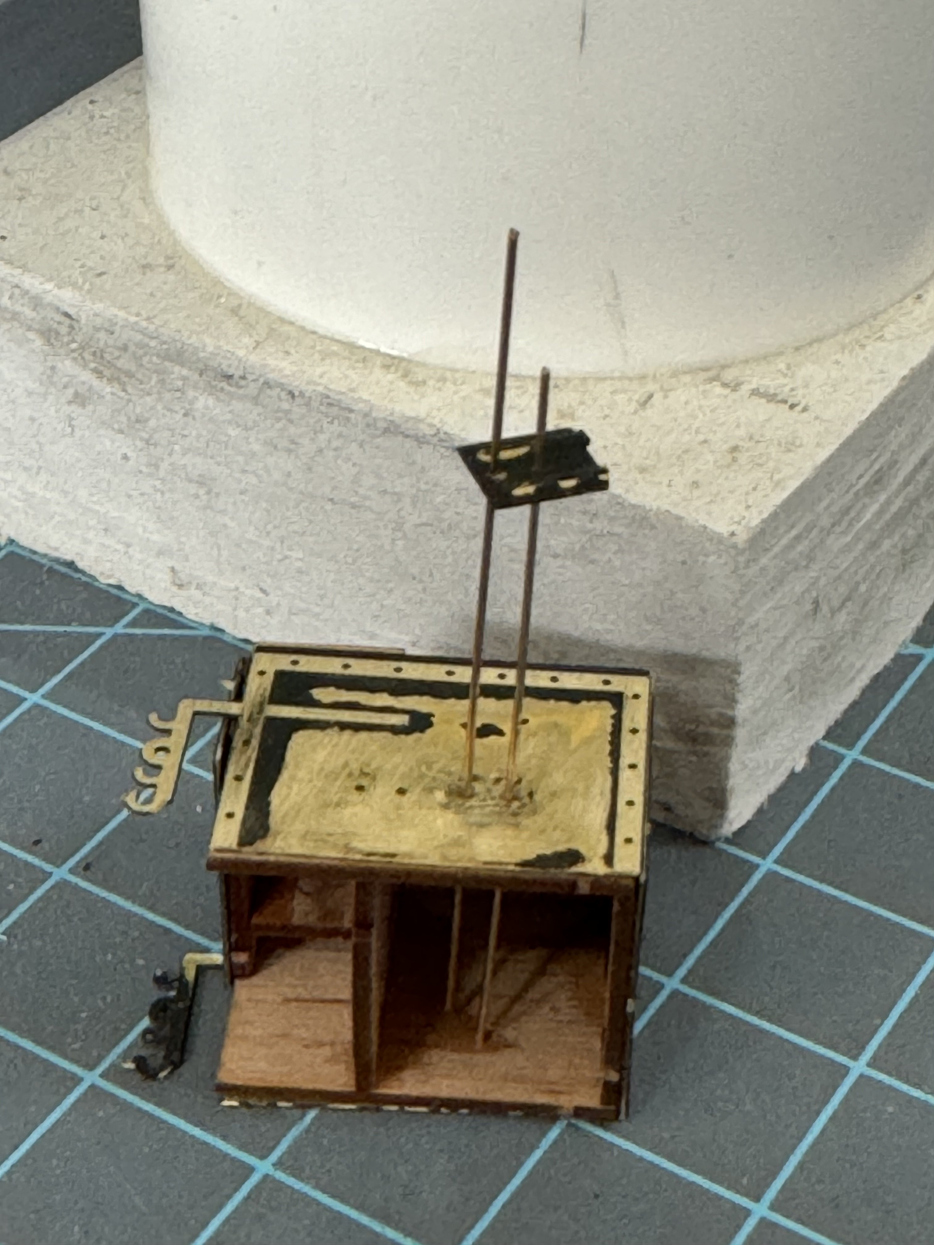
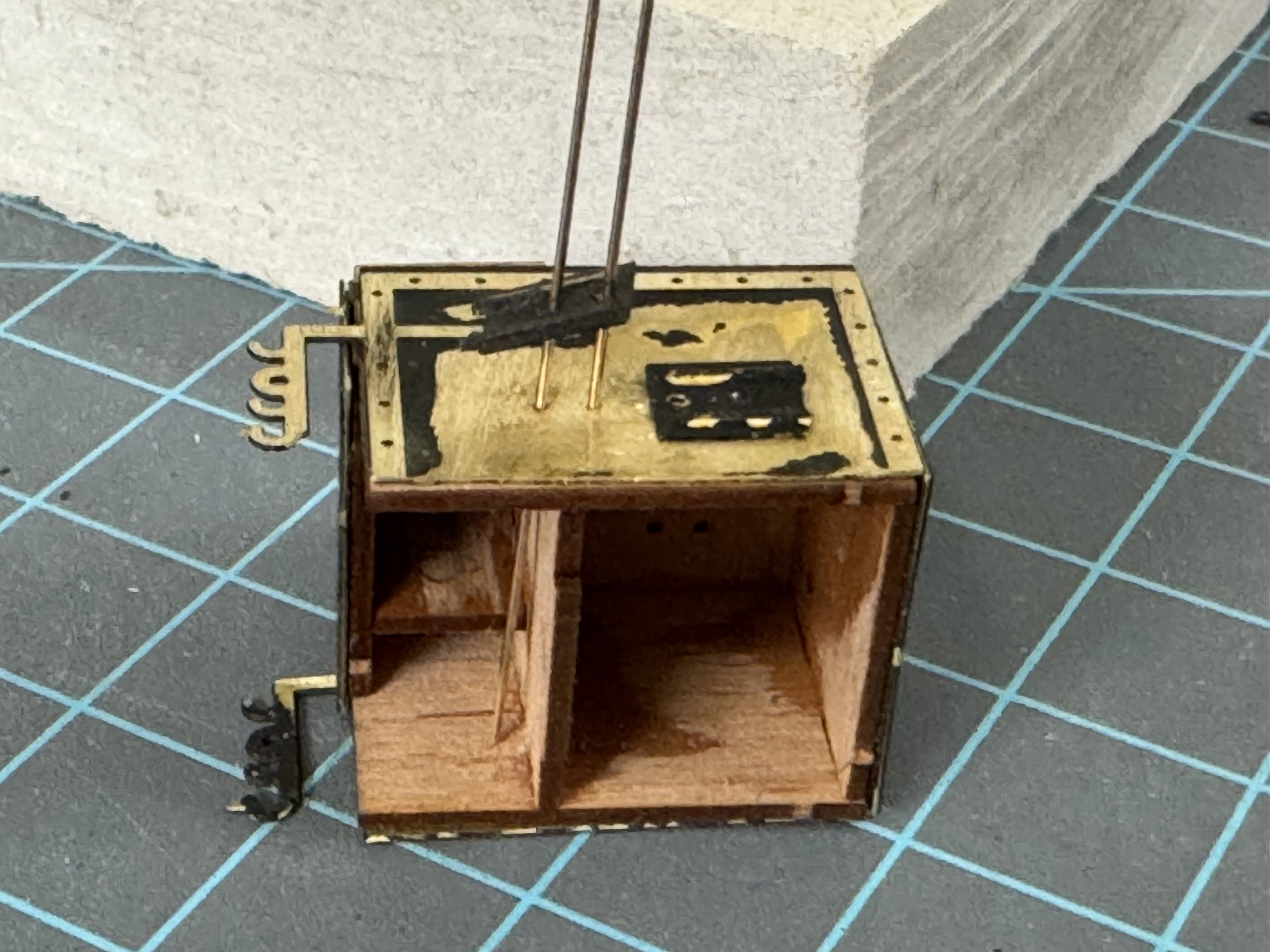
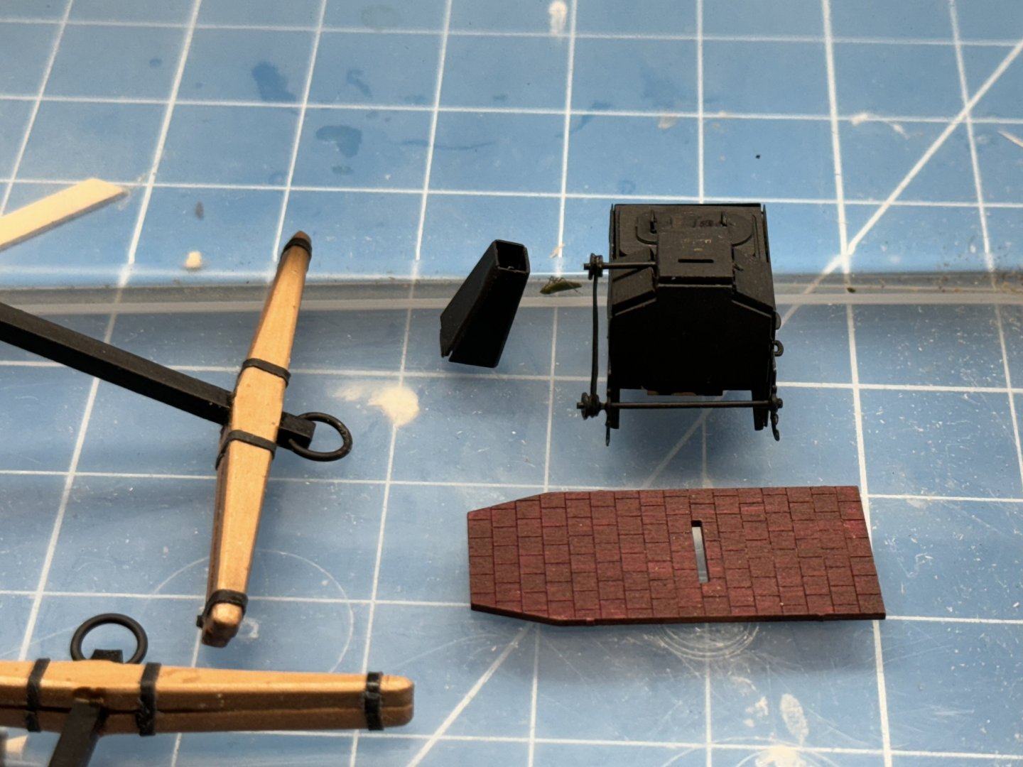
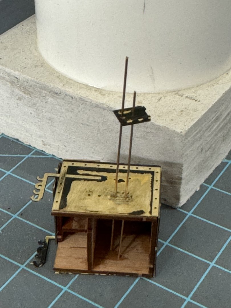
So on to the stove. Assembly per the instructions proceeded apace until I came to the doors and covers on the top and side of the stove (firehearth I think it was called). Anyway the objective is to get the doors/covers which have two holes in each aligned with the holes that are in the sides/top of the stove assembly. The holes as provided are pretty small; smaller than a #76 (0.200"/.05mm) drill bit. To give myself a fighting chance of getting the holes lined up I drilled them out to #76 on the doors/covers and stove. I cut two pieces of .020" phosphor-bronze wire (two slightly different lengths but long enough to stand proud of the stove side/top when inserted and stopped on the far side/bottom (aka workbench). Then I threaded the door onto the wire. Two different lengths makes this a bit easier. Slide the door down the wires, placed an ever so small drop of thick CA under where the door will land and pressed the door down and once seated used a toothpick to hold in place while gently removing the wires. Forgive the pealing black paint - these parts were oversprayed while painting something else and had not been prepped so the paint is not sticking and I sanded some of what did stick off so the CA will bond the metal not the paint.. Hopefully all will be better once the stove is assembled and finally painted. So the "proof in the pudding" is whether the handles will now fit into the doors/covers since that was the whole purpose of have the holes line up in the first place. Not so fast - the handles are square (maybe rectangular) in cross section and the holes are round. Turns out, at least on this version the handles are too big to fit into even the drilled out holes. I had to go to a #74 (.0225/.57mm) drill to get the handles to fit. There was enough friction getting them it that I did not use any glue - they are just "sitting there". The numbers on the wood were put there as they came off the carrier sheet although as it turns out they are pretty "self-identifying". Now on to the chain drive and flue.

- 422 replies
-
- 2
-
-
- Vanguard Models
- Sphinx
- (and 1 more)
-
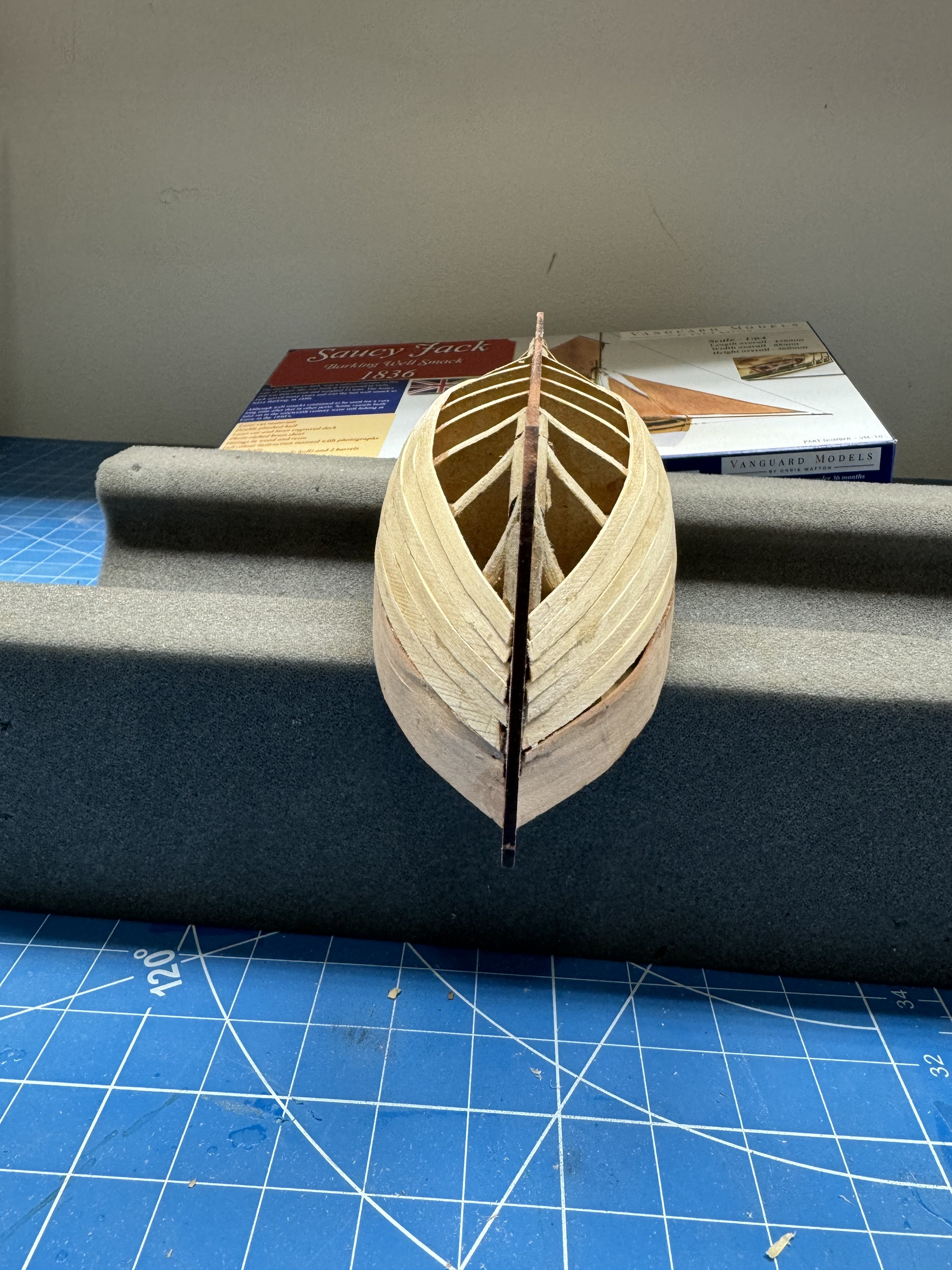
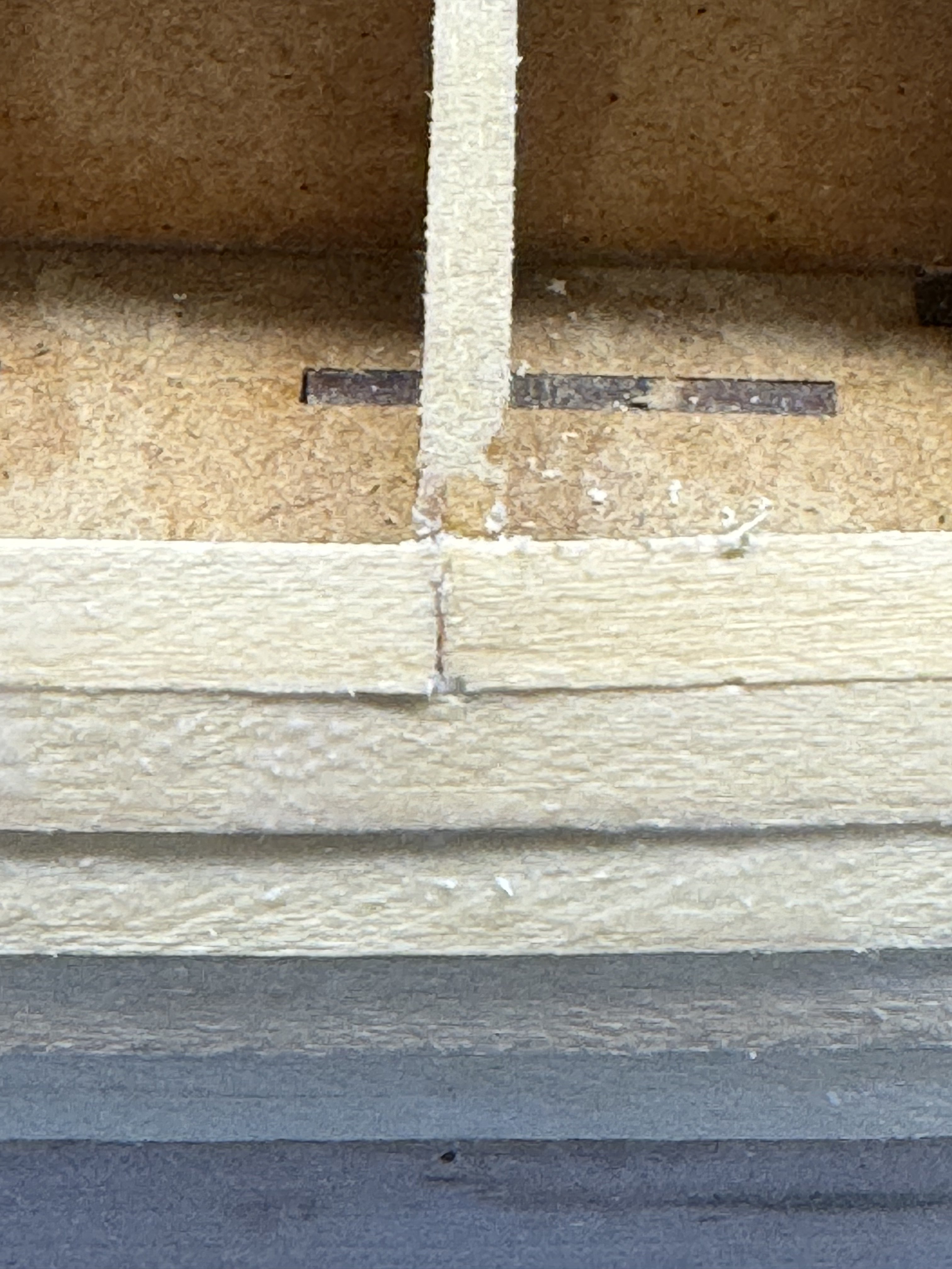
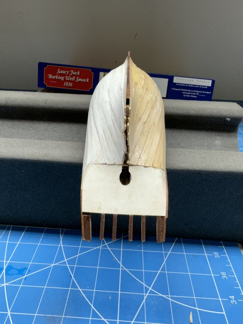
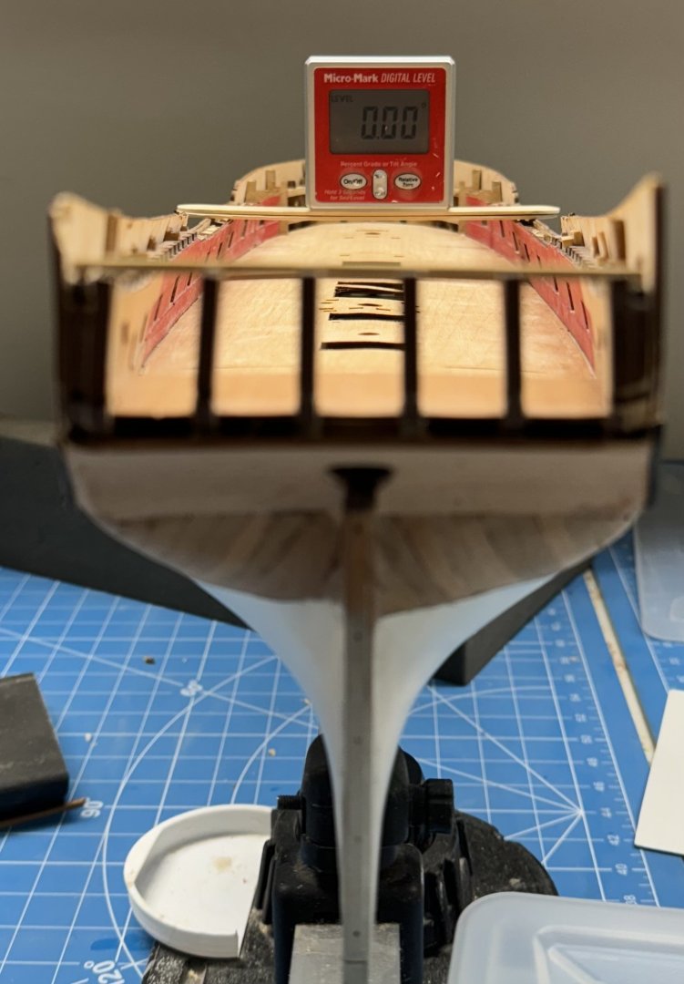
When I got to the port side fifth row I decided to split that plank. This is the plank (at least on this side) that completes the more or less horizontal run of planks - the next row will start up the stern post area. I had to do a little surgery on the supporting bulkheads as I thought there was too much vertical movement at the very aft end of the plank. But in the end I think it worked out okay. Because I did not get the stern transom pattern on exactly in the center (as you can see below) the starboard side fifth row will not land in the same place as the port. I am not sure what I will do about that now - perhaps use a slightly wider plank (at least the after half) and use the extra width at the stern to bring the plank to the horizontal/vertical transition like the port side.


-
I have four rows of planking on each side completed and have used a single plank in each row from stem to stern so far. Unlike some of my previous attempts at hull planking this time I am using medium CA to attach the planks to the bulkheads, one at a time after appropriate (I hope) tapering, so far only at the bow. After the plank is in place I use a small brush and paint 50/50 PVA/H2O in the joint between planks. so far so good - I will put two or three more rows from the op then and the garboard plank and work up to meet the upper band. I want the last row of planks to be below the turn of the bilge where what inevitably turns out to be a pretty "unusual" run of planking is not too visible - although this is only the first layer I need the practice.

- 42 replies
-
- 2
-
-
- Saucy Jack
- Vanguard Models
- (and 1 more)
-
Thanks druxey - they have to be done at some point, why not now while awaiting the new Sphinx kit so I can make another attempt at correctly assembling the hull. I can't wait to do another double set of planking.
- 422 replies
-
- 1
-
-
- Vanguard Models
- Sphinx
- (and 1 more)
-
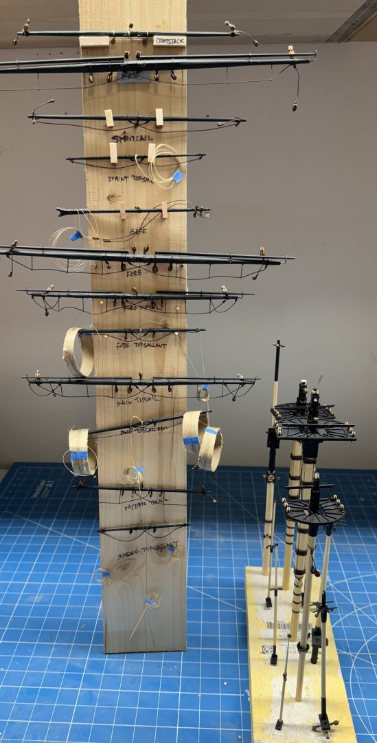
All the masts, yards and associated items completed. On to the stove, capstan, rudder etc. New Sphinx kit procurement approved by "higher authority" so I better not screw this one up "or else"!
- 422 replies
-
- 7
-
-
- Vanguard Models
- Sphinx
- (and 1 more)
-
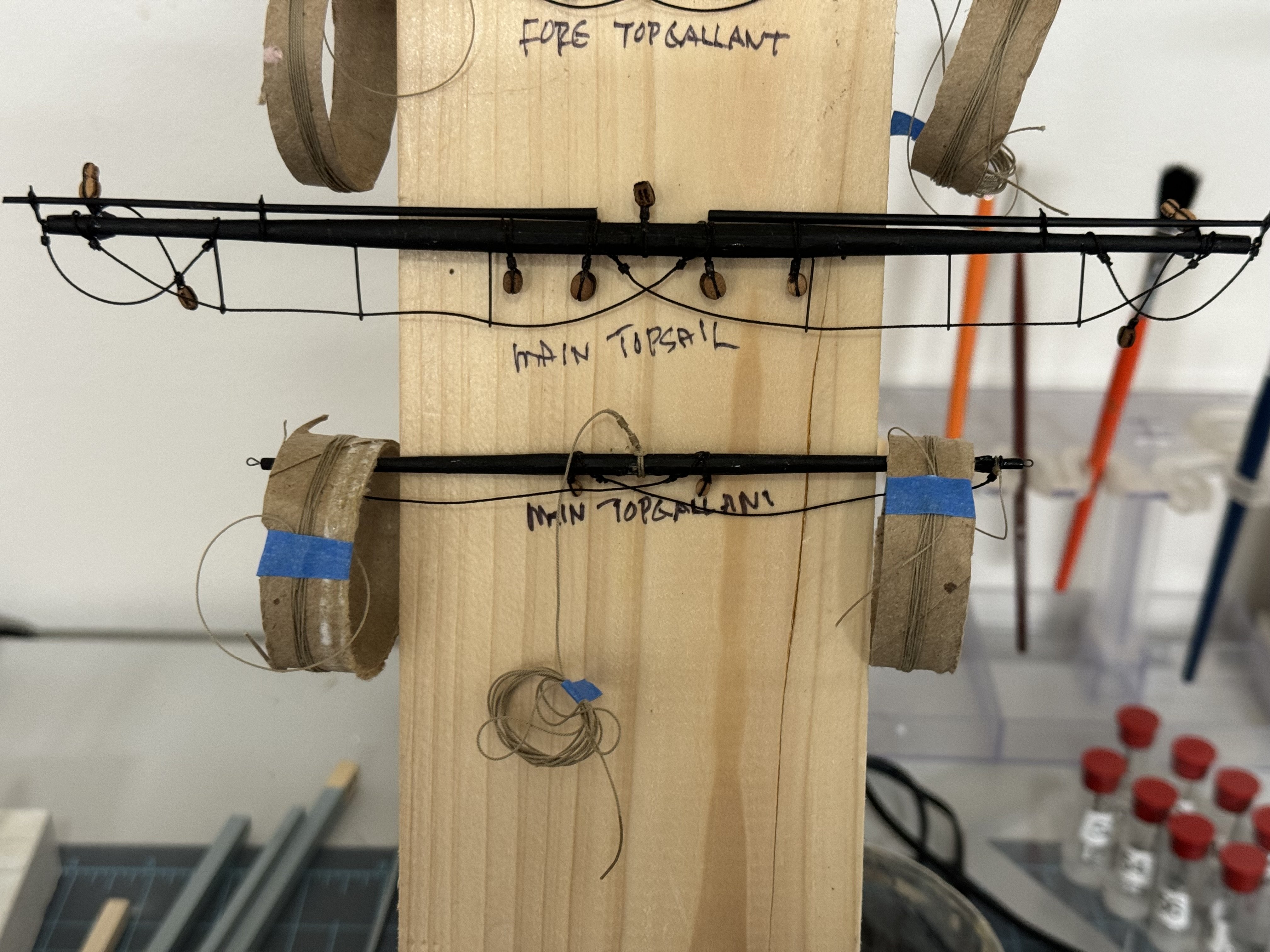
Here are the Main Top Sail and Top Gallant yard arms joining the rest of the "family". Mizzen Top Sail and Top Gallant to go.

- 422 replies
-
- 7
-
-
- Vanguard Models
- Sphinx
- (and 1 more)
-
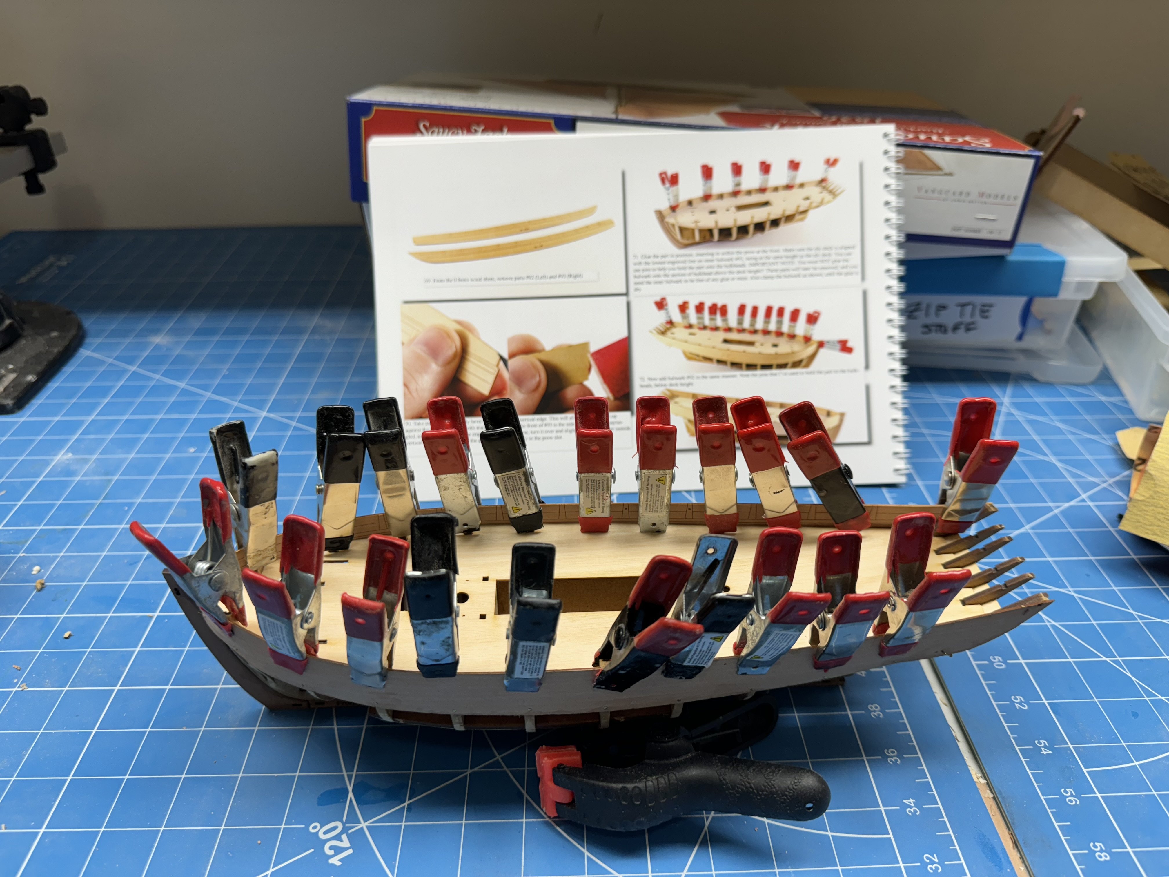
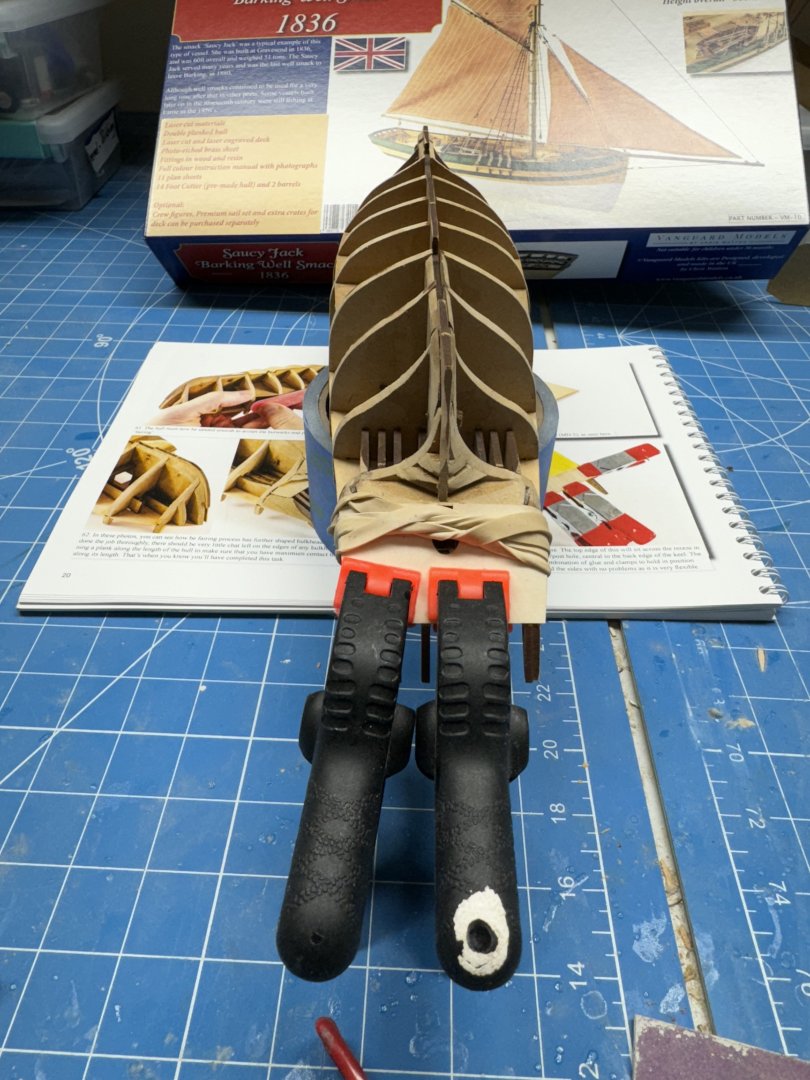
Inner bulwark (parts 92 and 93) pinned in position and "painted" with 60/40 PVA/H2O I will let this dry overnight and then the real fun begins tomorrow.

- 42 replies
-
- 1
-
-
- Saucy Jack
- Vanguard Models
- (and 1 more)
-
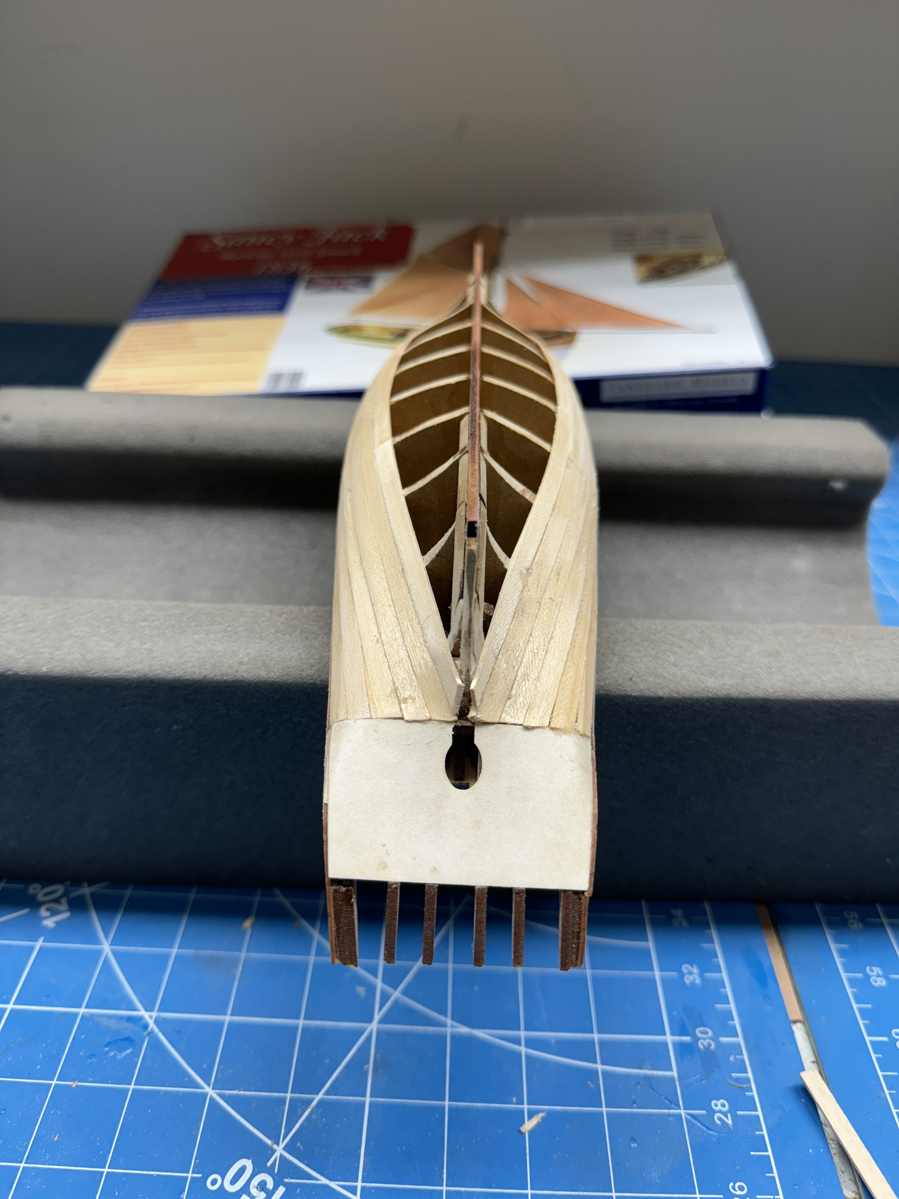
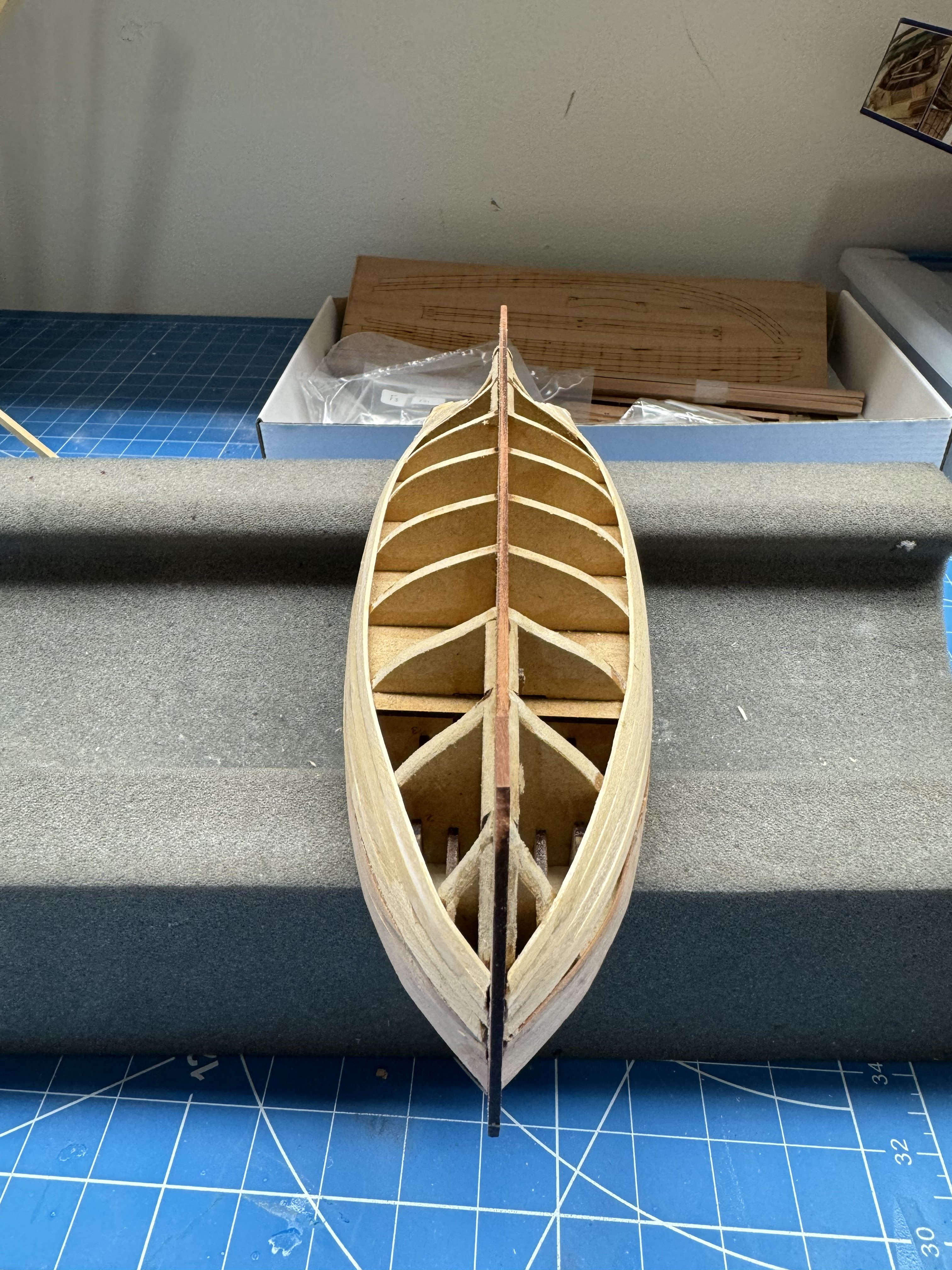
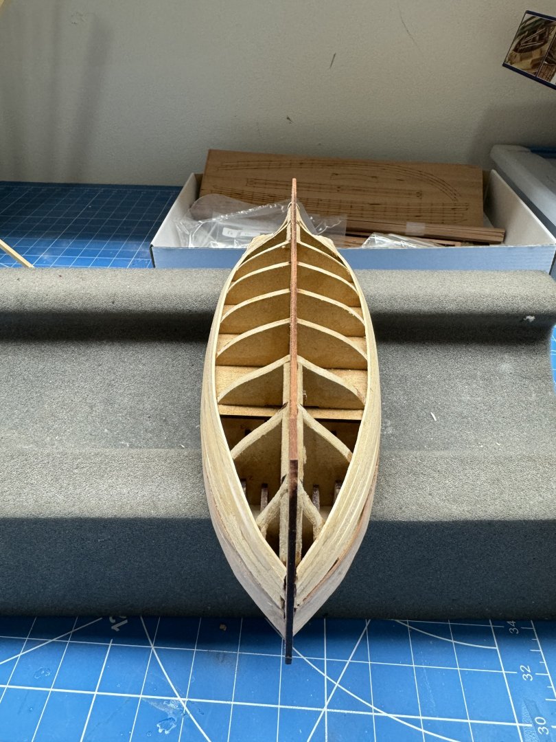
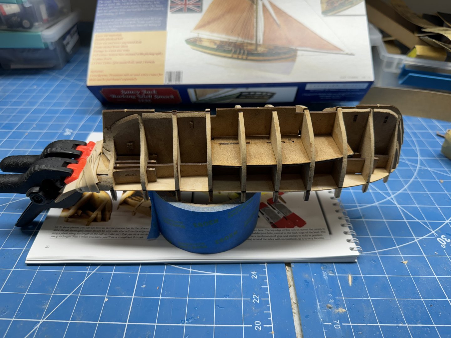
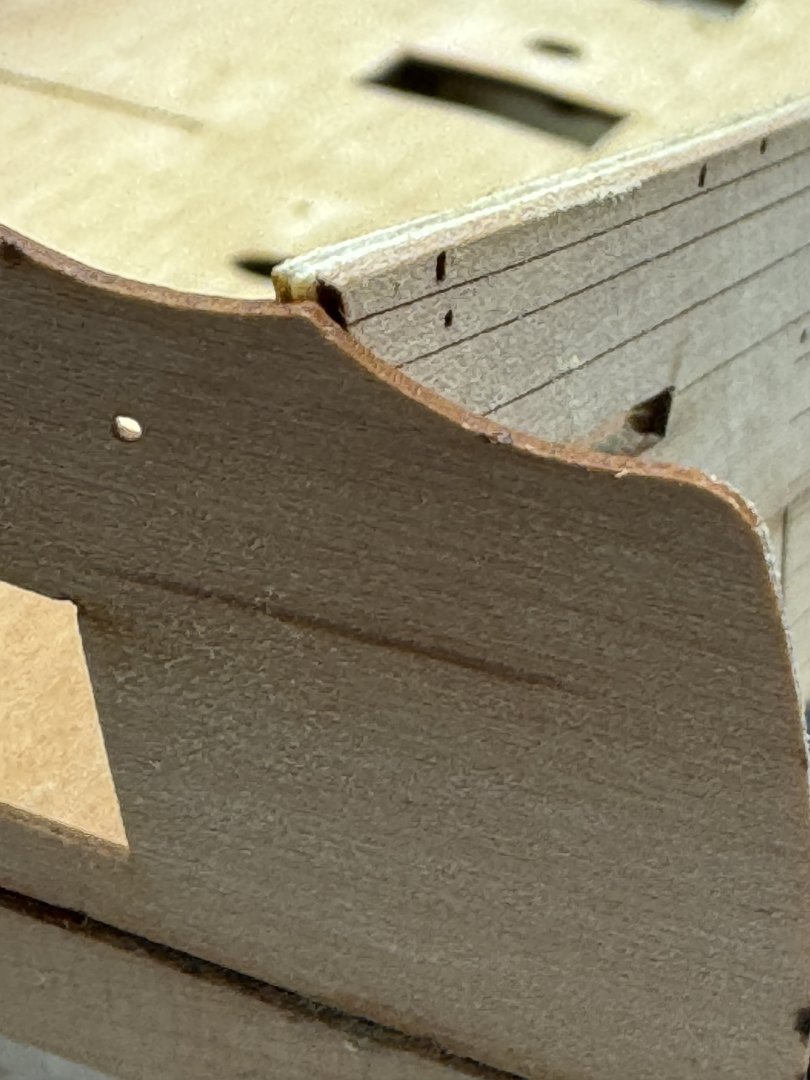
One of the things I really like about the Vanguard kits is how quickly the hull structure goes together. Here after less than two days efforts I am almost ready to start planking. Once the lower counter dries (I used full strength PVA since you have to get the forward corners to wrap around the structure) I add the keel and stem and then "let the planking (first layer) begin!
- 42 replies
-
- 4
-
-
- Saucy Jack
- Vanguard Models
- (and 1 more)
-
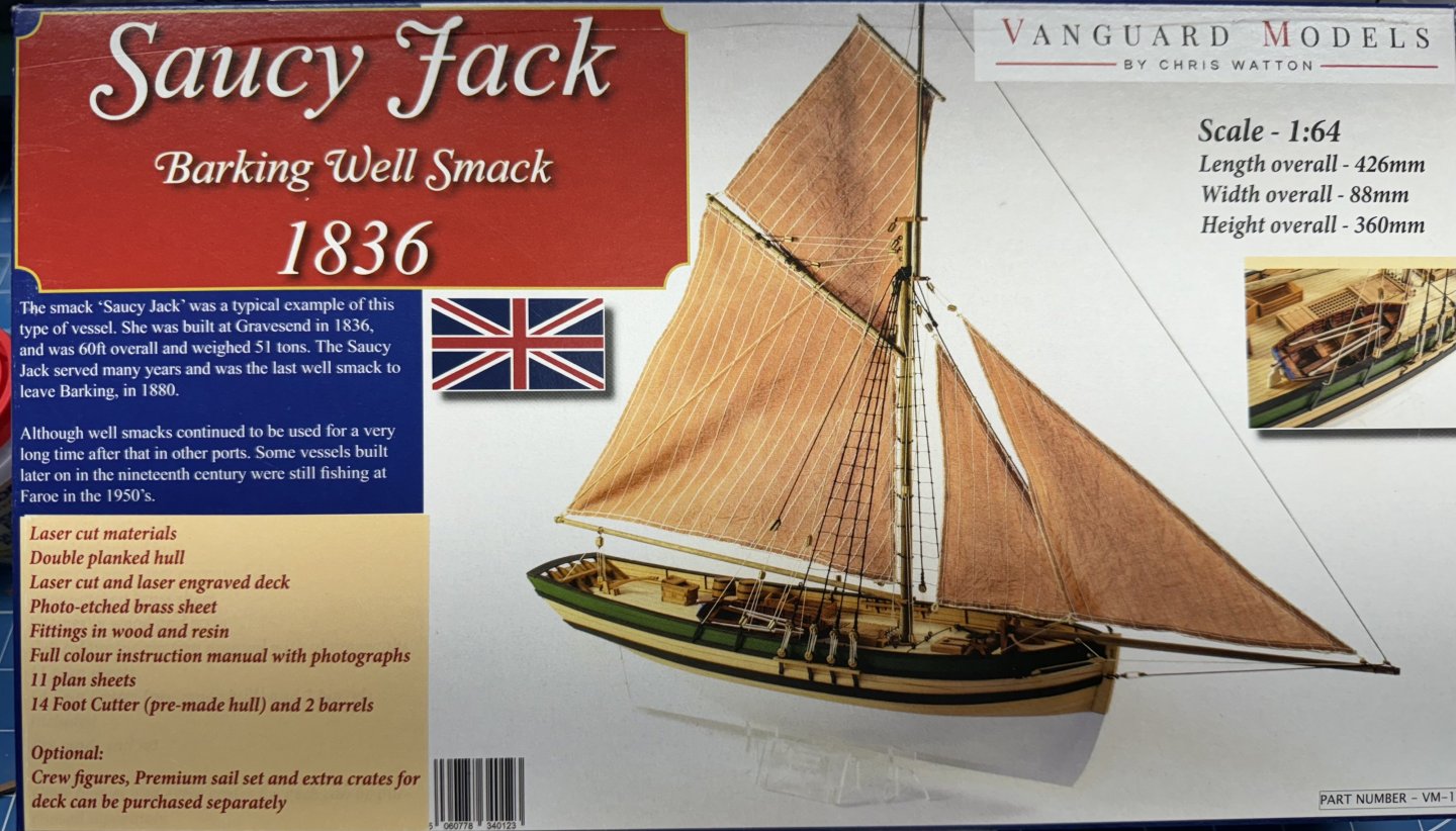
Girlfriend wanted a ship model to fit in a specific space, constrained both horizontally and vertically. This one fits the requirements so her we go. I have some experience with vanguard kits so think I know what to expect, more or less.
- 42 replies
-
- 2
-
-
- Saucy Jack
- Vanguard Models
- (and 1 more)
-
When I started to enlarge the gun ports I realized that one of the "unintended consequences" was that the gun ports (at least the aft four or five on the starboard side are now going too be to large and the provided covers will no longer fit. And when I trimmed the out bulwark I had to remove a goodly number of the pre-drilled holes which I am sure will cause a problem later. Soooo - I am going to pause the Sphinx hull construction and work on the spars, rudder, stove, capstan etc. and hope for an inspiration to strike or "she who must be obeyed" approves another Sphinx kit.
- 422 replies
-
- 2
-
-
- Vanguard Models
- Sphinx
- (and 1 more)
-
So the "plan" as far as I have thought it through so far: Finish adding the pieces to the stern. Cut out the interfering pieces at the top of the gun ports - otherwise some of the aft cannon will not fit. Adjust the top of the starboard bulwark so it meets the top of the stern fascia; tapering so that nothing is removed from the front section. Cut the bottom of the locating "tab" on the upper part number 45 so the tab is only 1mm thick (versus 2mm unaltered). This will have the part 45 sit 1mm lower than "normal". Thin from the top the upper part 45 to 1.5mm (versus 2mm) which will lower the top of the upper part 45 by another .5mm. Repeat these actions on the other part 45 and part 45a. Assume that a 1.5mm adjustment will be sufficient to bring the two sides into a least much better alignment. I have not yet figured out what the "unintended consequences" of these actions will but I highly suspect there will be some.

- 422 replies
-
- 2
-
-
- Vanguard Models
- Sphinx
- (and 1 more)
-
Thanks for the posts guys - it helps to have more than one set of eyes on the problem. I decided to proceed with the lower transom installation and then see how the windows look before taking any other action. In the meantime I am finishing up the yard arms - only four more to go.
- 422 replies
-
- 3
-
-
- Vanguard Models
- Sphinx
- (and 1 more)
-
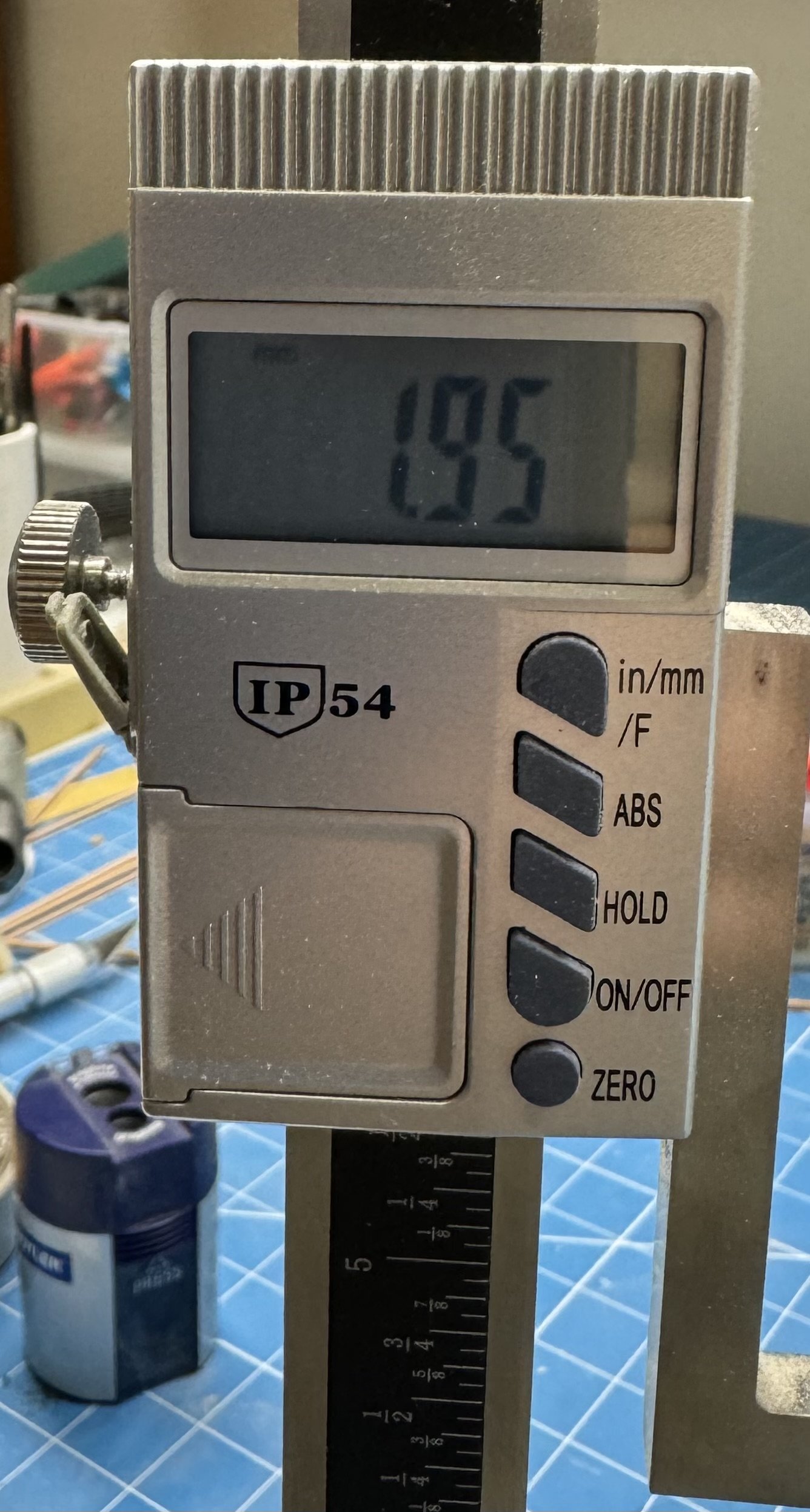
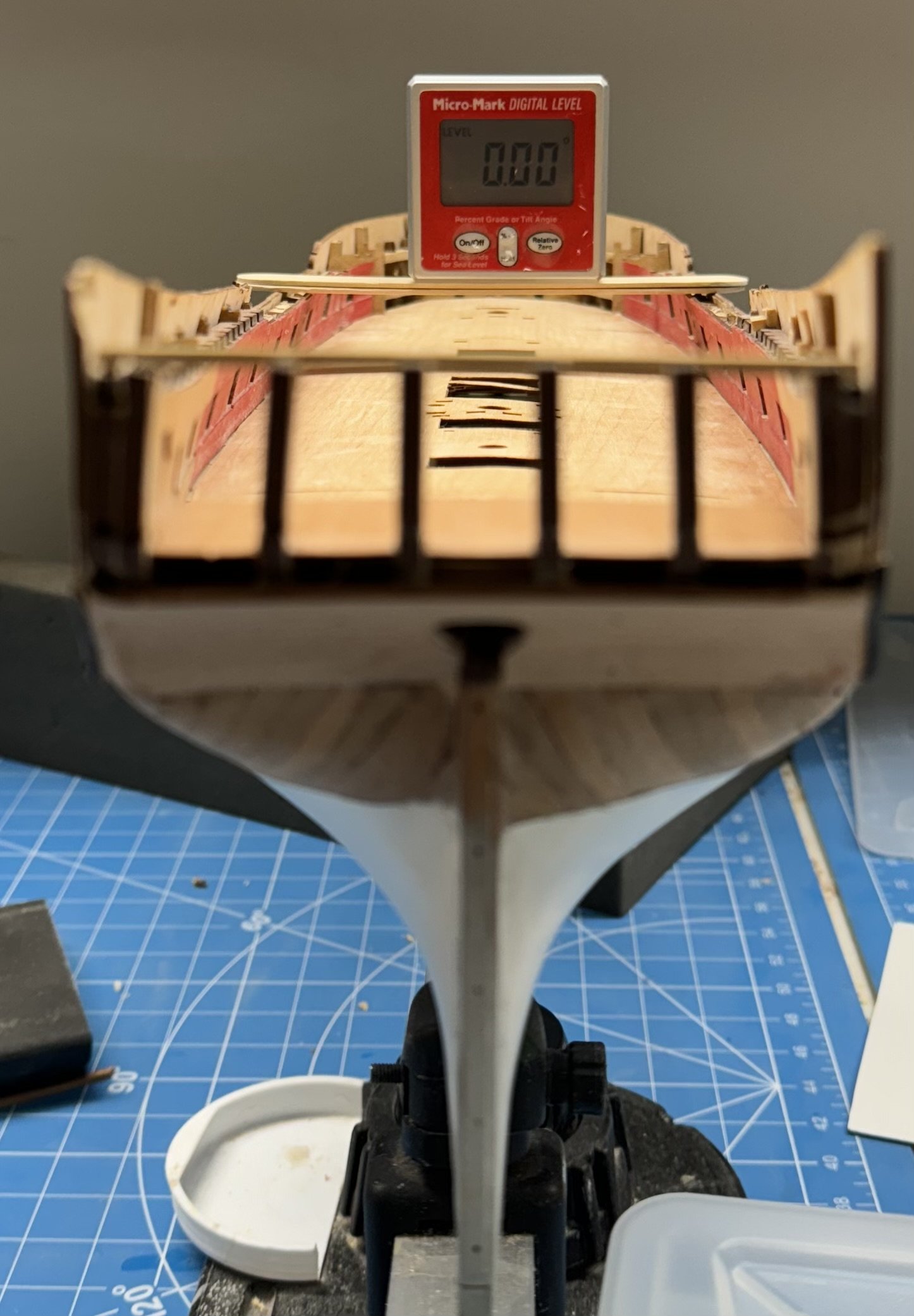
Well, not being able to leave well enough alone I decided to see what the impact of the misaligned sides might be. My first thought was one side of the qdeck beams would be higher than the other but I measured all 18 beam slots and they were less than 1mm different from one side to the other so it appears that will not be a bigger issue than it would otherwise (on Wincheslea it took me quite a bit of effort to get the qdeck beams to fair correctly). So I decided to check the locations of the qgallery slots - If I am correct then the starboard side should be 2mm (+ or -) higher than the port. So I put the hull back in the Amati holder and adjusted to get it as level as I could. It appears the mis-match is only on the after piece of the lower bulwark so I put the digital level across the hull amidships. And using my digital height gauge confirmed that the starboard side slots for the qgallery is 2mm higher than the port. So the qgalleries will be misaligned by that much unless I take measures (not sure what those might be at this point) to correct it. And yes, I still have to fix the waterline issue at the stern.

- 422 replies
-
- 2
-
-
- Vanguard Models
- Sphinx
- (and 1 more)
-
Thanks Kurt - I am going to put Sphinx on the shelf for now. I have another small Vanguard kit that I am going to work on while I consider my options here other than starting over with a new kit and throwing out all the stuff I won't need/use (although having a second set of parts is not necessarily a bad thing).
- 422 replies
-
- 1
-
-
- Vanguard Models
- Sphinx
- (and 1 more)
-
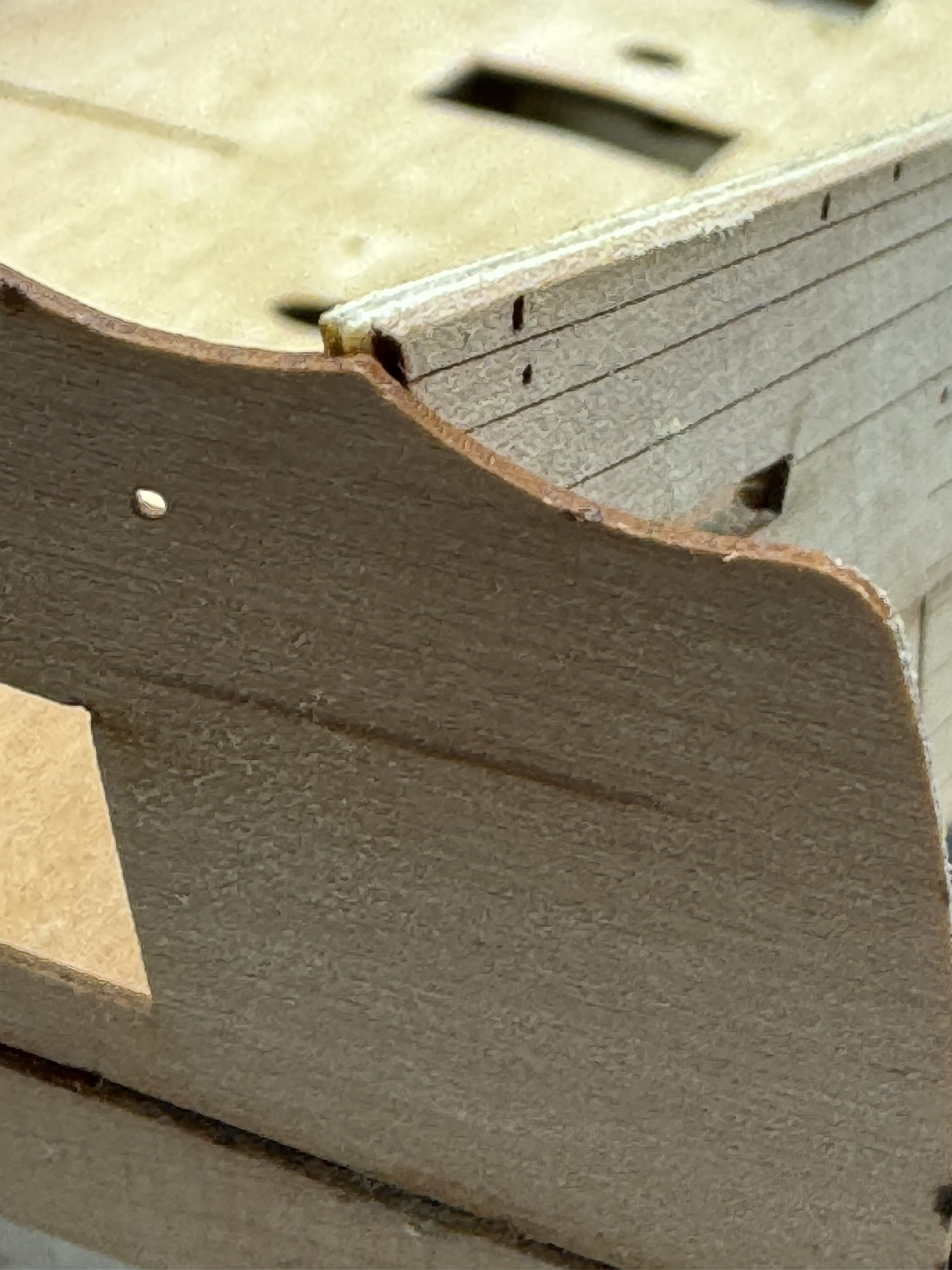
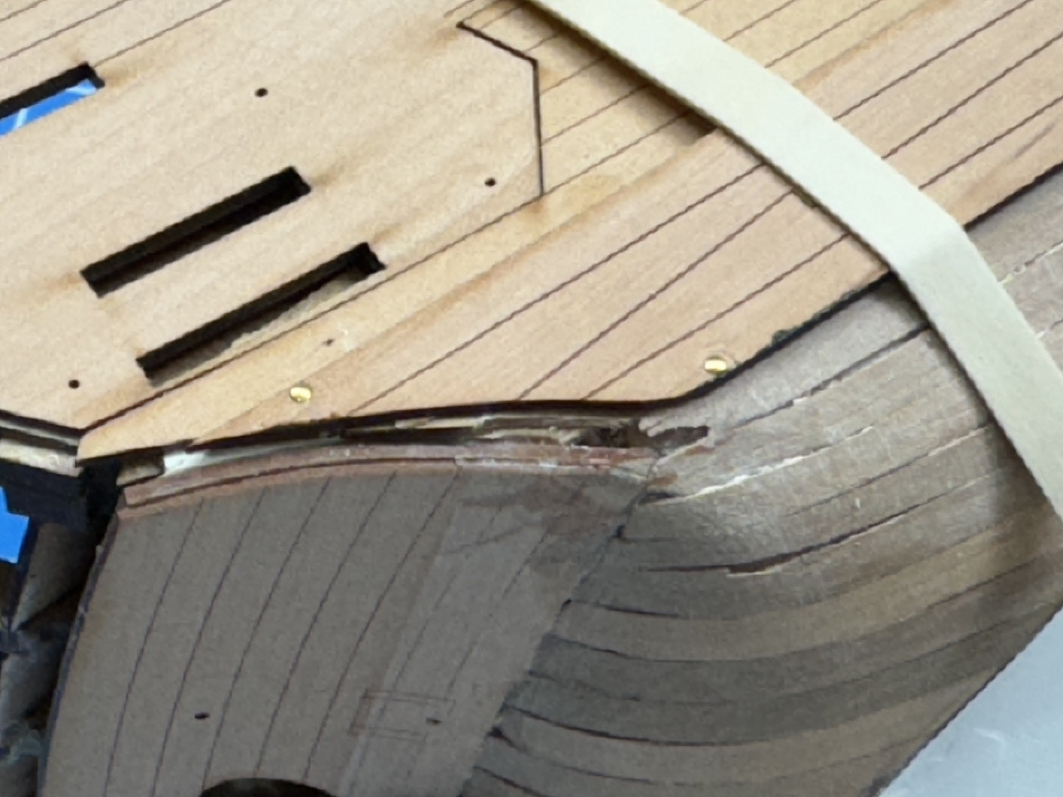
Just when I thought things might be going as planned I noticed this: It would appear that I got the outer bulwark on the starboard side on with the stern higher than it should be. I guess it was the lower, outer bulkhead that is too high but I just noticed it now. As you can see the inner bulwark is about 2mm lower than the outer at the rearmost gun port. The gap gets progressively smaller until at gun port 6 it is "gone". Clearly this is going to cause a problem fitting the stern transoms, windows et al. Not sure what to do at the moment but am trying to figure out what my options might be.
- 422 replies
-
- 2
-
-
- Vanguard Models
- Sphinx
- (and 1 more)
-
Allan, I can take no credit for simply adding the parts provided in the kit. I did deviate from what was provided in the kit and made the masts starting with rectangular stock instead of the provided dowels. Same with the yards arms as many of them are octagonal in the center section. I find it easier to make something octagonal round than something round octagonal.
- 422 replies
-
- 1
-
-
- Vanguard Models
- Sphinx
- (and 1 more)
-
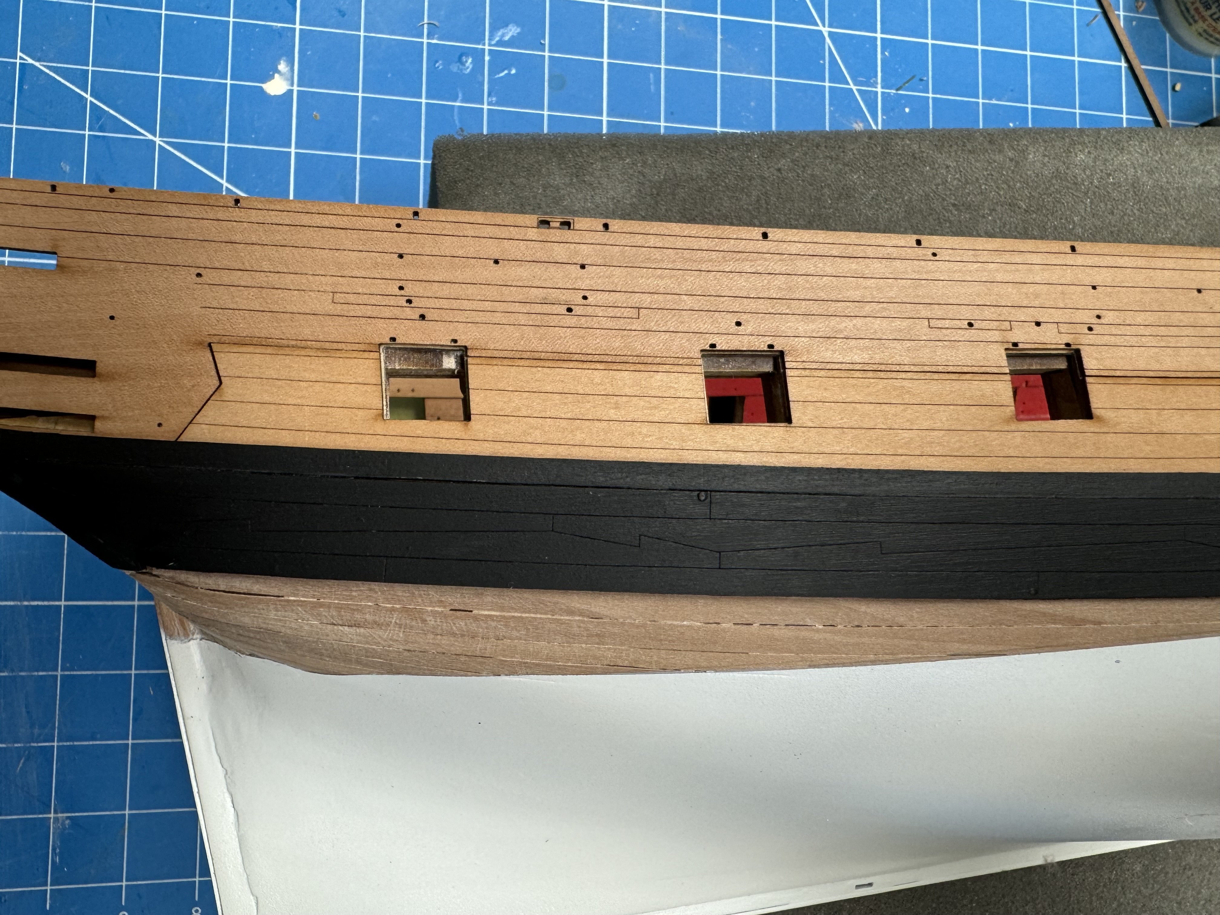
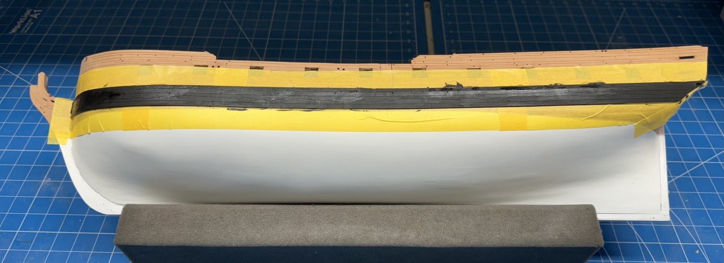
I installed the pre-bent wales on the hull using a combination of dilute white glue and pins. I used a combination of 60/40 PVA and a drop or two of medium CA to add the " Strip Above Main Wales" on the port side. I had originally intended to paint these pieces completely black before installing but given they are only half as thick as the wales thought better of that remembering how the liquid in the dilute PVA caused various other thin parts to curl I opted to just paint the upper edge before installing. That limited painting did not cause any twisting/curling and the two port side pieces were glued on without incident. Not trusting my less than steady hand I decided to mask off the area above and below the wales before painting by hand. I recognize that the instructions paint this and the quarter gallery backgrounds at the same time but since I am not spraying these it does not (IMHO) make any difference when the painting is done. So here is the port side after painting before the masking tape is removed. I did not remove the pins but just painted over the heads. probably less unsightly than the empty holes but then maybe they would be mistaken for small scuppers.
- 422 replies
-
- 4
-
-
- Vanguard Models
- Sphinx
- (and 1 more)
-
Mugie - Thanks Paint had no effect on the wood - other than turning it black. I thought about doing both edges but the upper edge will be mostly covered by the "Strip Above Main Wales" parts numbers 71 - 74 - which I will paint black before installing.
- 422 replies
-
- 1
-

-
- Vanguard Models
- Sphinx
- (and 1 more)
-
Starboard side wales in place a glue setting. I put a pin in all the holes that were not scuppers. I painted to bottom edge black before gluing it on so I won't have to try and get a clean edge at the bottom - not that it being unpainted would be all that noticeable - it does still have the laser char on it. I am not sure what is going to happen at the stern as the wales seem to be a bit short of covering the transom. Maybe a "fashion piece" is included with the kit or I may have to make my own.


- 422 replies
-
- 6
-
-
- Vanguard Models
- Sphinx
- (and 1 more)
-
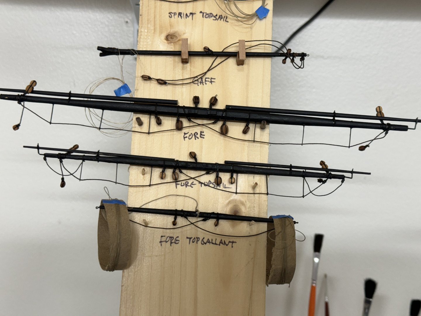
While waiting for paint and pear wood to dry I completed assembly and outfitting of the Fore, Fore Topsail and Fore Topgallant yard arms.
- 422 replies
-
- 6
-

-
-
- Vanguard Models
- Sphinx
- (and 1 more)