HOLIDAY DONATION DRIVE - SUPPORT MSW - DO YOUR PART TO KEEP THIS GREAT FORUM GOING! (Only 24 donations so far out of 49,000 members - C'mon guys!)
×


cdrusn89
-
Posts
1,915 -
Joined
-
Last visited
Content Type
Profiles
Forums
Gallery
Events
Everything posted by cdrusn89
-
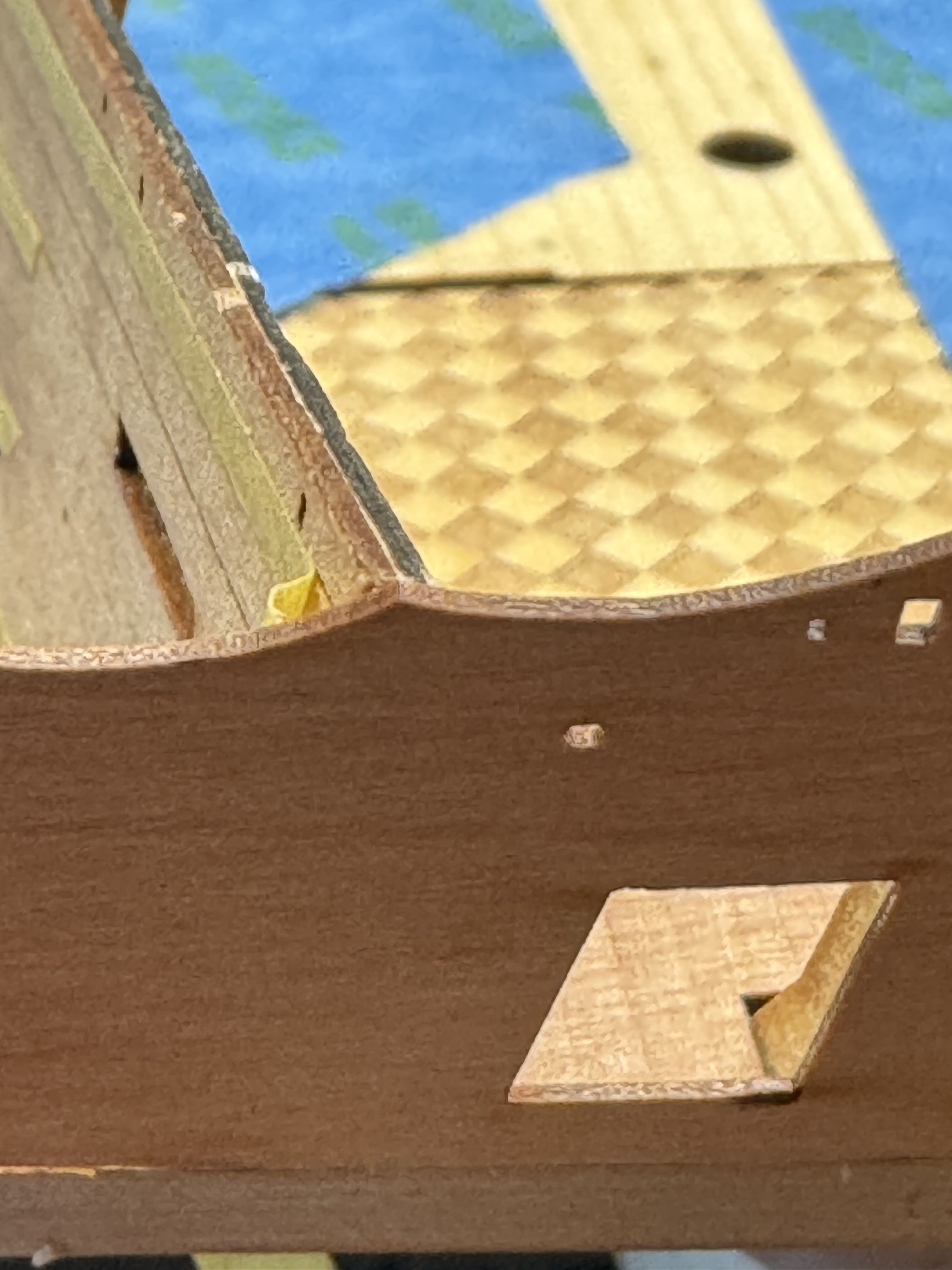
 Now on to the lower finishing patterns. I followed the instructions to glue the two small pieces together but then decided maybe trying to shape these as a single piece might not be (for me) the way to go. I could not find a drawing of the finished pattern without all the decorations/molding so I thought it best to fit it one piece at a time. And since this piece crosses over the wales as a single piece it would have to be "adjusted on both the front (facing out) and back so it will sit against the hull. I am not a great fan of mdf but appreciate it is easier to shape than "real" wood but the part 29 (2mm mdf) I started with started to "disintegrate" after the first bit of shaping with 120 sanding stick. That and since the space between the bottom of the gallery (on my model) and the top of the wales was just a hair over 3mm I decided to fashion a part 29 replacement out of 3mm pear using the "residue from the 3mm carrier sheet. Here is the original part 29 and the replacement piece in its final form before installation. It took a good bit of sanding (which would have been easier but my disk sander is "out of commission" awaiting the refinishing of the garage floor where the power tools are located (powers that be have been most emphatic about power tools in the house (vacuum and kitchen appliances excepted)). And here is the first "layer" dry fit below the gallery. And I filled in the gap below the windows (but not yet sanded.
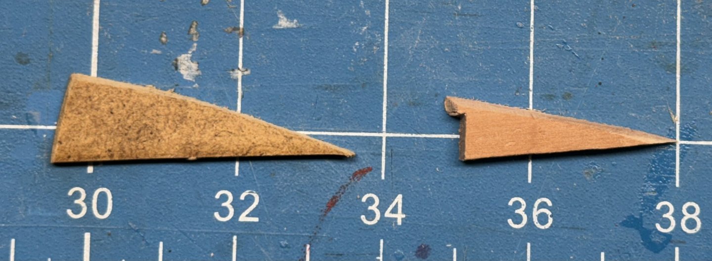
- 422 replies
-
- 5
-

-
- Vanguard Models
- Sphinx
- (and 1 more)
-
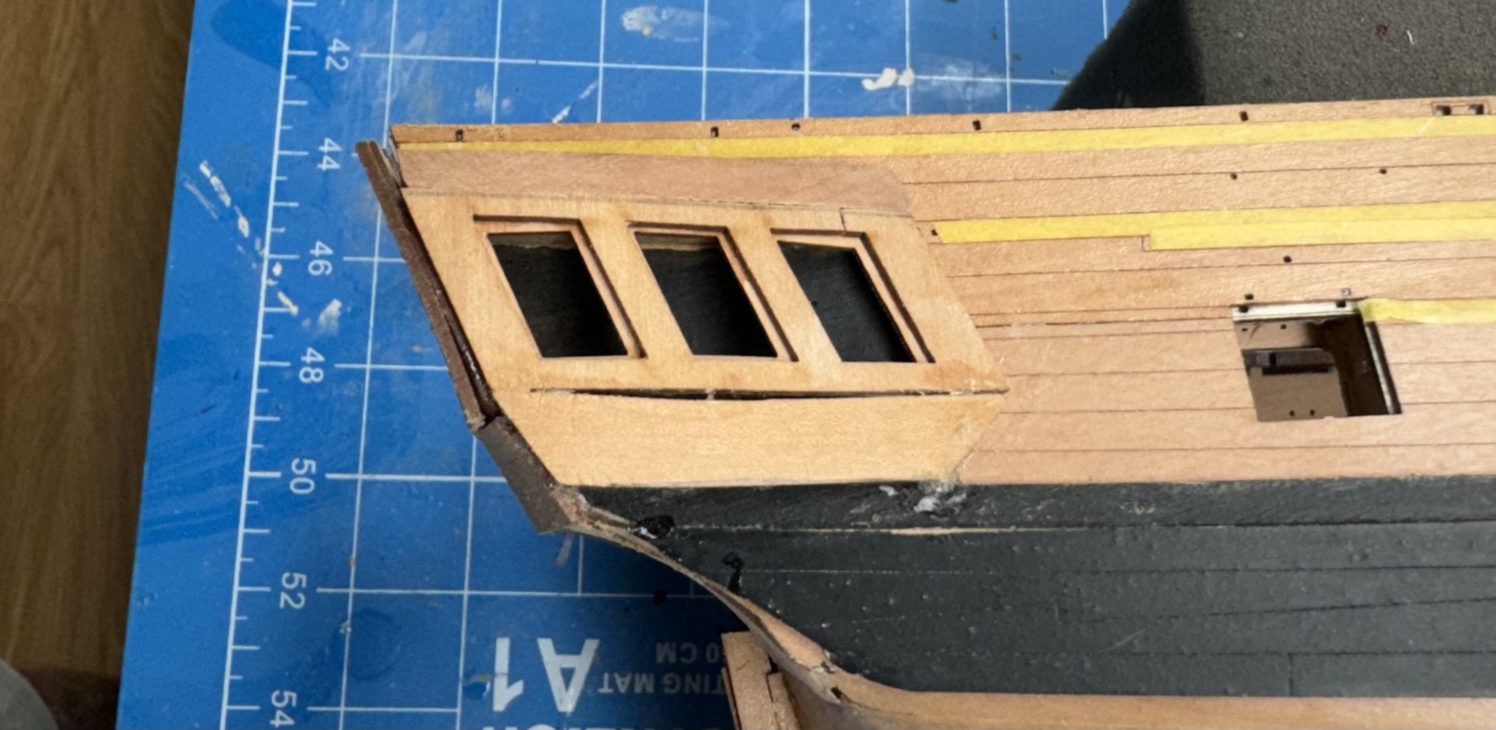
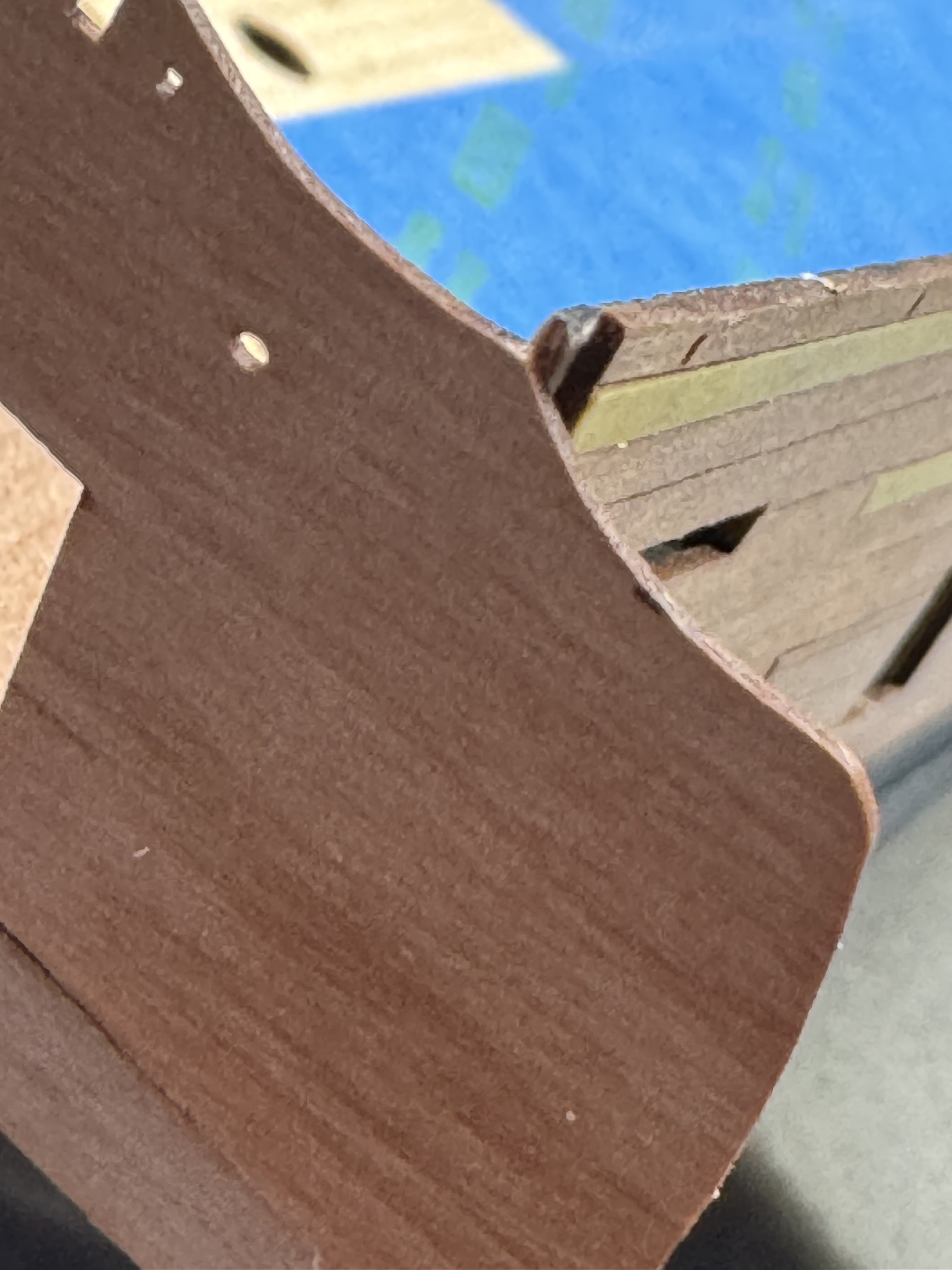
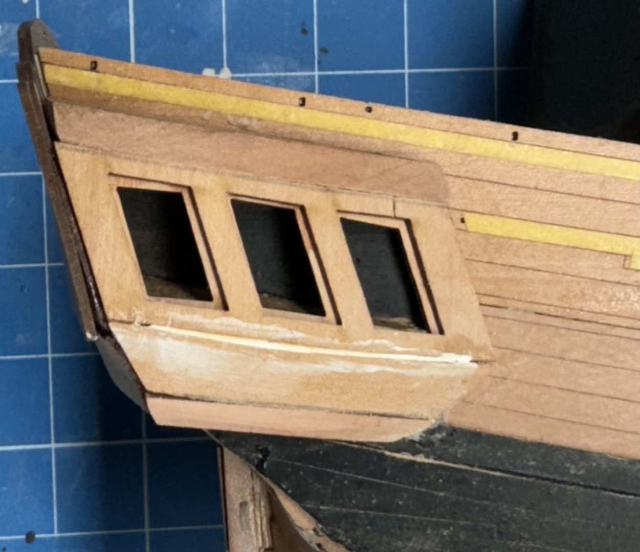
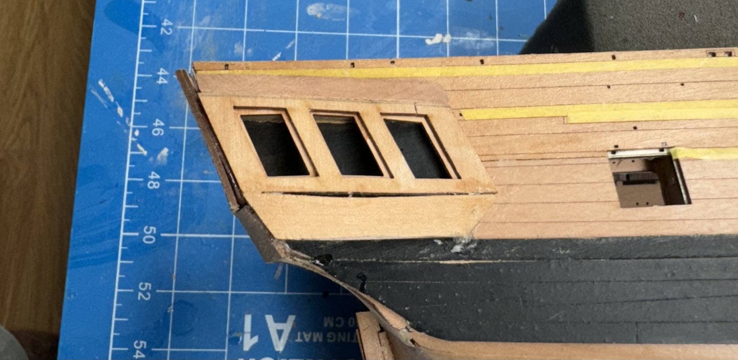
Thanks Ronald. So on to the quarter galleries. First off the pictures in the instructions show the patterns too low as we moved the stern items lower than was done on the prototype. Second while the window pattern go on more less without incident (aside from cracking the outer pattern as you can see) the lower "berthing" patterns are another matter. As you can see I could not get the curvature of the pattern to match the windows even after I added a small spacer on top of the 45a pattern. Third getting the berthing pattern glued on is a challenge because I could got find a way to clamp it in spite of owning what my girl friend claims is every clamp ever made. I finally had to resort to medium CA and holding it with my hands. I will fill in the gap and no one will be the wiser as this area has molding along it and decorations above and below.
- 422 replies
-
- 3
-
-
- Vanguard Models
- Sphinx
- (and 1 more)
-
While waiting for the stern fascia to dry I dabbed some small bits of Minwax Golden Oak wood filler over the areas where I sanded thru the pear and it looks better. A few coats of flat poly and it might look even less conspicuous.
- 422 replies
-
- 8
-
-
- Vanguard Models
- Sphinx
- (and 1 more)
-
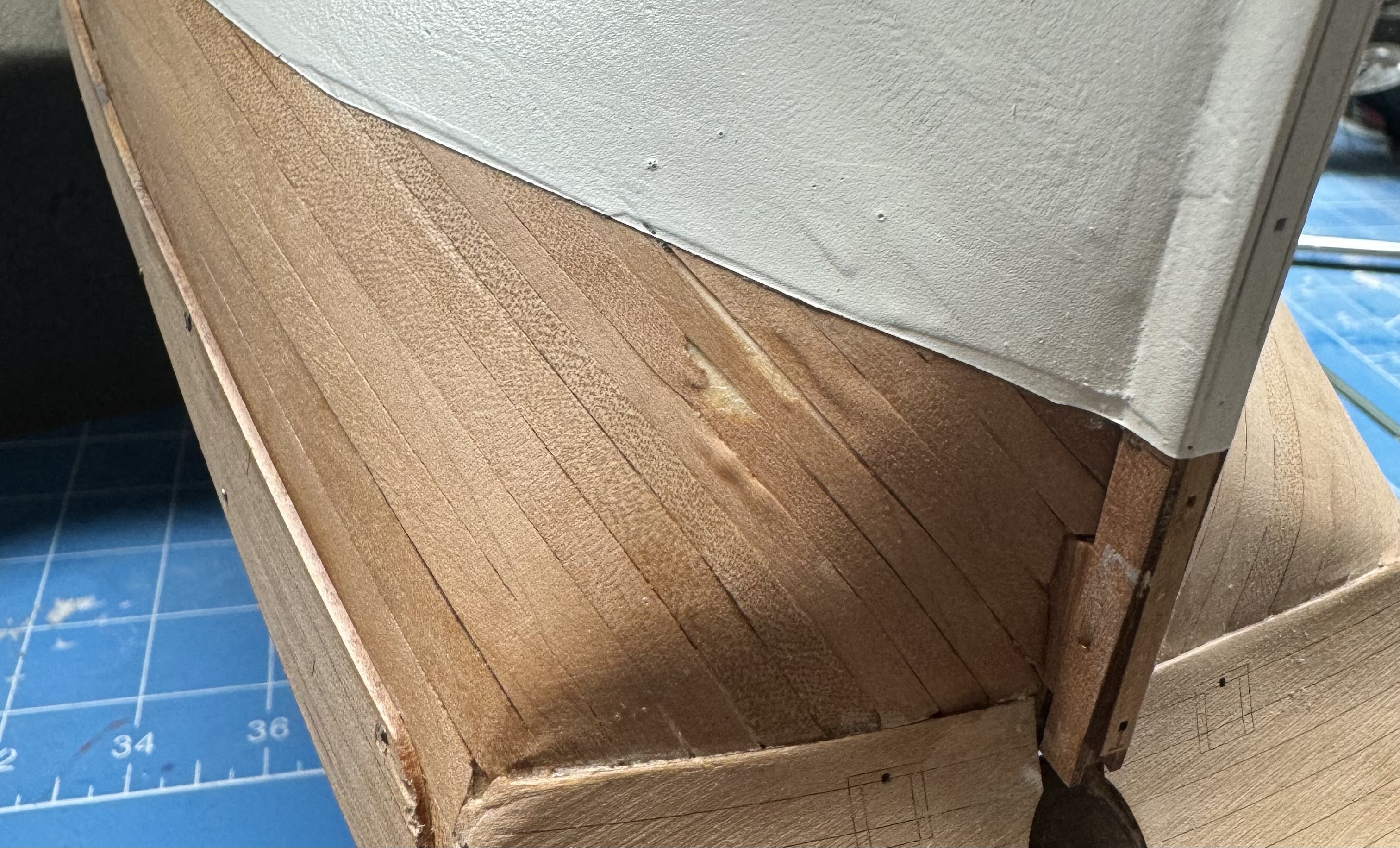
Thanks Ronald. Hull is not so smooth close up which is why I only post pictures of the hull which hides many sins, so to speak. Now that the wales are done I moved on to adding the upper counter and stern fascia. And as Yogi Berra is reputed to have said Deja vu all over again. The two sides are at different heights AGAIN! It is not as bad as last time - just over 1mm as best I can measure but still 🤐 My plan is to "split the difference " and trim down the high side .7mm (or so) and add a .7mm (aka a very long thin triangle) to the low side and adjust the "lay of the molding" to match. But not until I get the quarter galleries done. I clearly do not "get it" during the bulwark installation process.


- 422 replies
-
- 3
-
-
- Vanguard Models
- Sphinx
- (and 1 more)
-
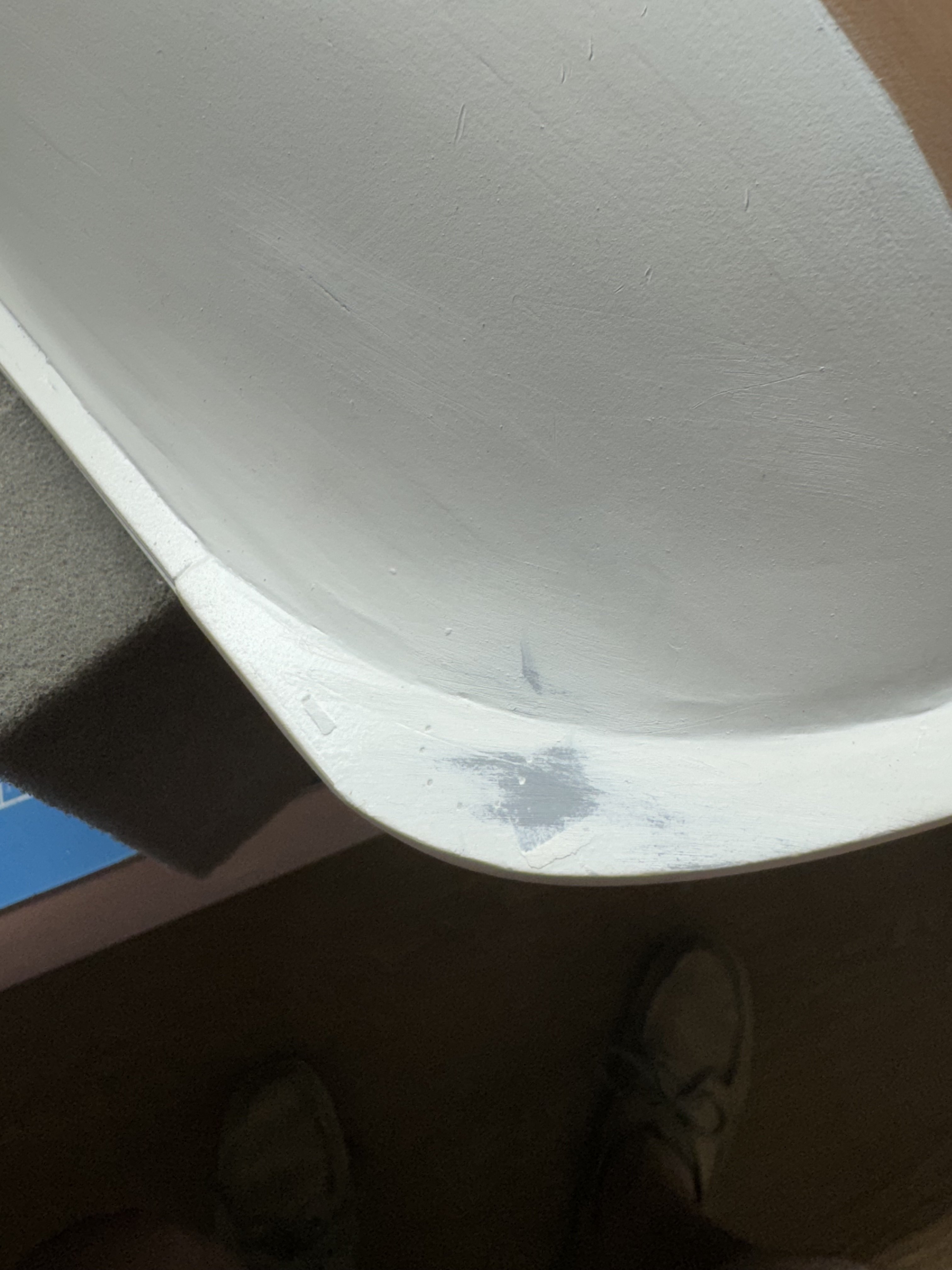
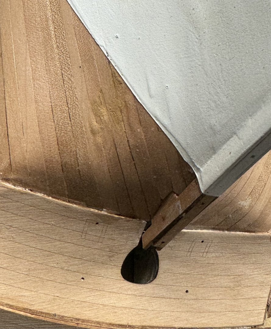
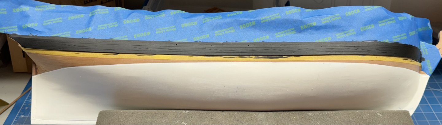
I noticed that I managed to sand all the way through the pear planking (in an area where it SHOWS) but have decided to not attempt any kind of repair now. It really is not in a high visibility area being somewhat "under the counter". I think at least my attempting some kind of stain (can't think of anything else to do) to reduce the color mismatch might very well make it more rather than less noticeable. Also in manipulating the hull around getting the wales on for "shaping" I managed (not sure exactly how) to mar the paint on the bow. I sanded it smooth(er) but have decided not to return to the paint booth until I have the quarter galleries in place in case some else happens during that process. And now for actual progress. I painted the upper edge of the pieces that go above the wales, and attached the pre-shaped wales to the starboard side - it took more than a few nails to get both edges down on the hull then added the "planks above wales". Once satisfied the glue was dry I pulled out the pins (except the two at the very front as I was scared of gouging up the surrounding parts getting the pins out and this area is pretty well covered by other parts going forward), filled the pin holes and carefully sanded them smooth. I put a coat of polycrylic on the wales and above wales planks, masked off above and below and hand painted two coats of flat black on the wales and the above wales planking once the polycrylic was dry. Now for the port side.


- 422 replies
-
- 6
-
-
- Vanguard Models
- Sphinx
- (and 1 more)
-
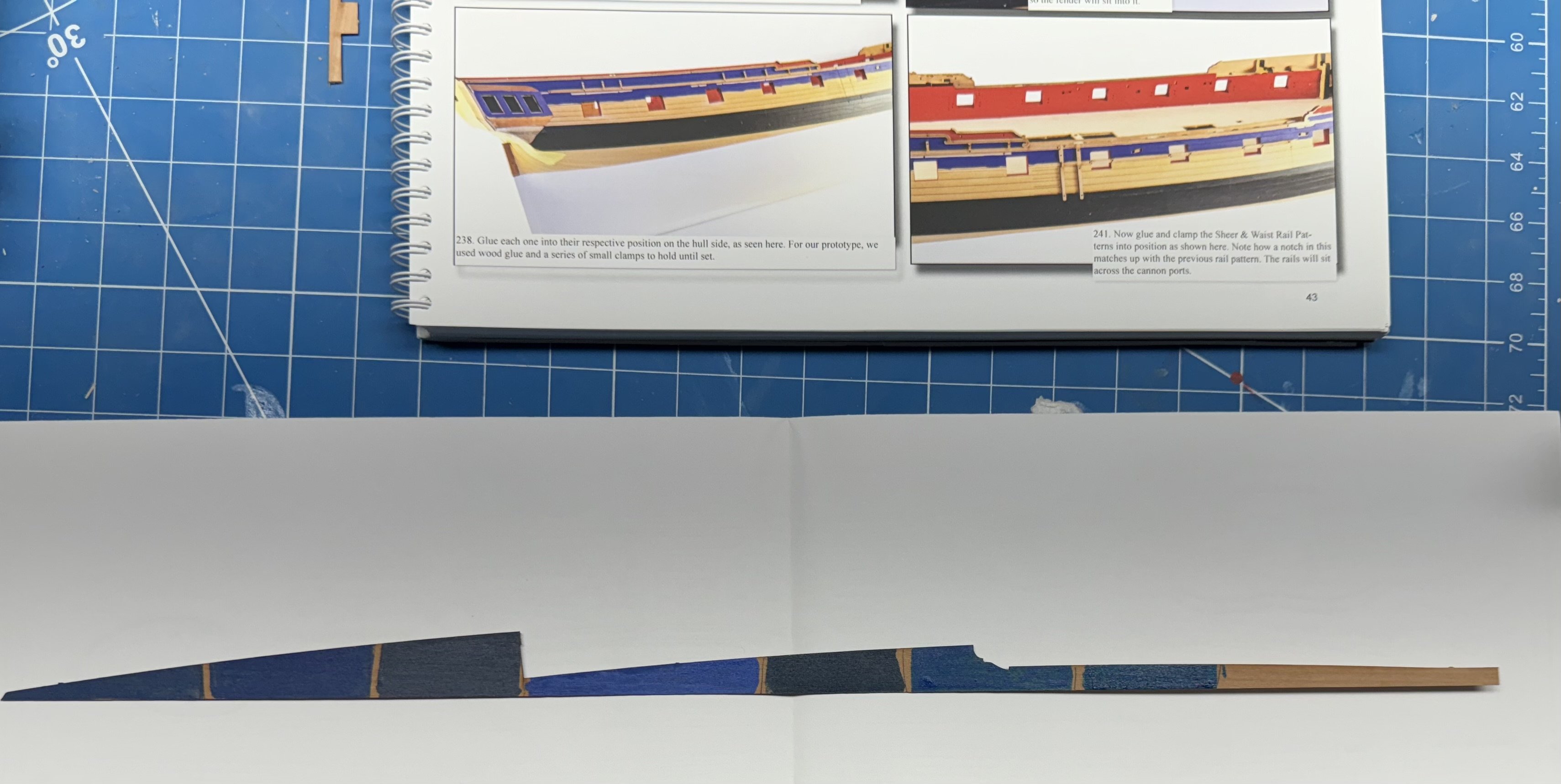
Looking ahead and trying to kill some time to make sure the hull is REALLY dry before starting the quarter galleries and wales I took inventory of the blue paint colors I have accumulated over the years (I started this hobby in earnest in 2010). Found seven different shades all but one from Badger and judging by the names (B&O Blue for instance) they appear to mostly based on train line colors). Anyway I cut a piece off the 0.8mm pear carrier sheets, put a coat of polycrylic flat (as the area to be painted already has a coat on it) on and then when dry (overnight) a sample of each of the seven colors I have. Here is what the sample looks like after all the gloss of wet paint has disappeared. The one in the middle (Vallejo Flat Blue) seems to be the closest the Humbrol 25 Flat Blue on the prototype in the manual. No decision required now as I have enough of all seven to cover the required areas.

- 422 replies
-
- 5
-
-
- Vanguard Models
- Sphinx
- (and 1 more)
-
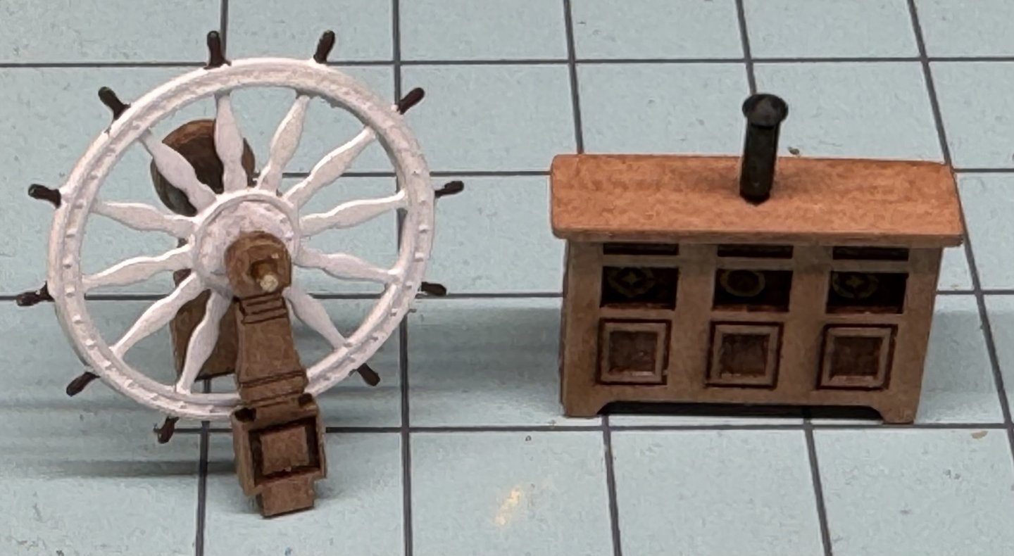
Continuing the assembly of "deck furniture" here are the ship's wheel and binnicle. I built one of the Syren ship's wheels but it is too big to fit and even though I tried to fabricate a way for it to fit in the end it looked too "clunky" so I am going with the kit provided wheel.
- 422 replies
-
- 4
-
-
- Vanguard Models
- Sphinx
- (and 1 more)
-
I had a "bobo" on the bow where somehow I managed to NOT get the white paint everywhere it should be so the hull is back in the paint booth for hopefully the last time unless I lose my senses and even consider spraying the exterior bulwarks. So to kill some time in a productive manner and avoid doing things "around the house" I built the belfry and the forescastle railings. Here they are after painting. I used double sided tape to hold down the really small pieces. I could not think of a better way to do it lacking those little "sticky sticks" I see the plastic model guys use. Speaking of tools I had a terrible time getting the railing posts on the railing "square". I did not attempt to get them at anything other than 90 degrees. I will handle the deck curvature at install. I finally used my parallel pliers to squeeze the post onto the railing after I cleaned up the laser char in the slots on both the railing and posts. A few drops of medium CA on the underside of the railing and "assembly complete".
- 422 replies
-
- 5
-
-
- Vanguard Models
- Sphinx
- (and 1 more)
-
I feel your pain on the delicate trim pieces. I worked on getting the char off the trim pieces outboard of the bulwarks forward. Managed to only break off the very upper curvy part on the biggest ones. I sometimes think we have traded molding scrapers and such for char removal
-
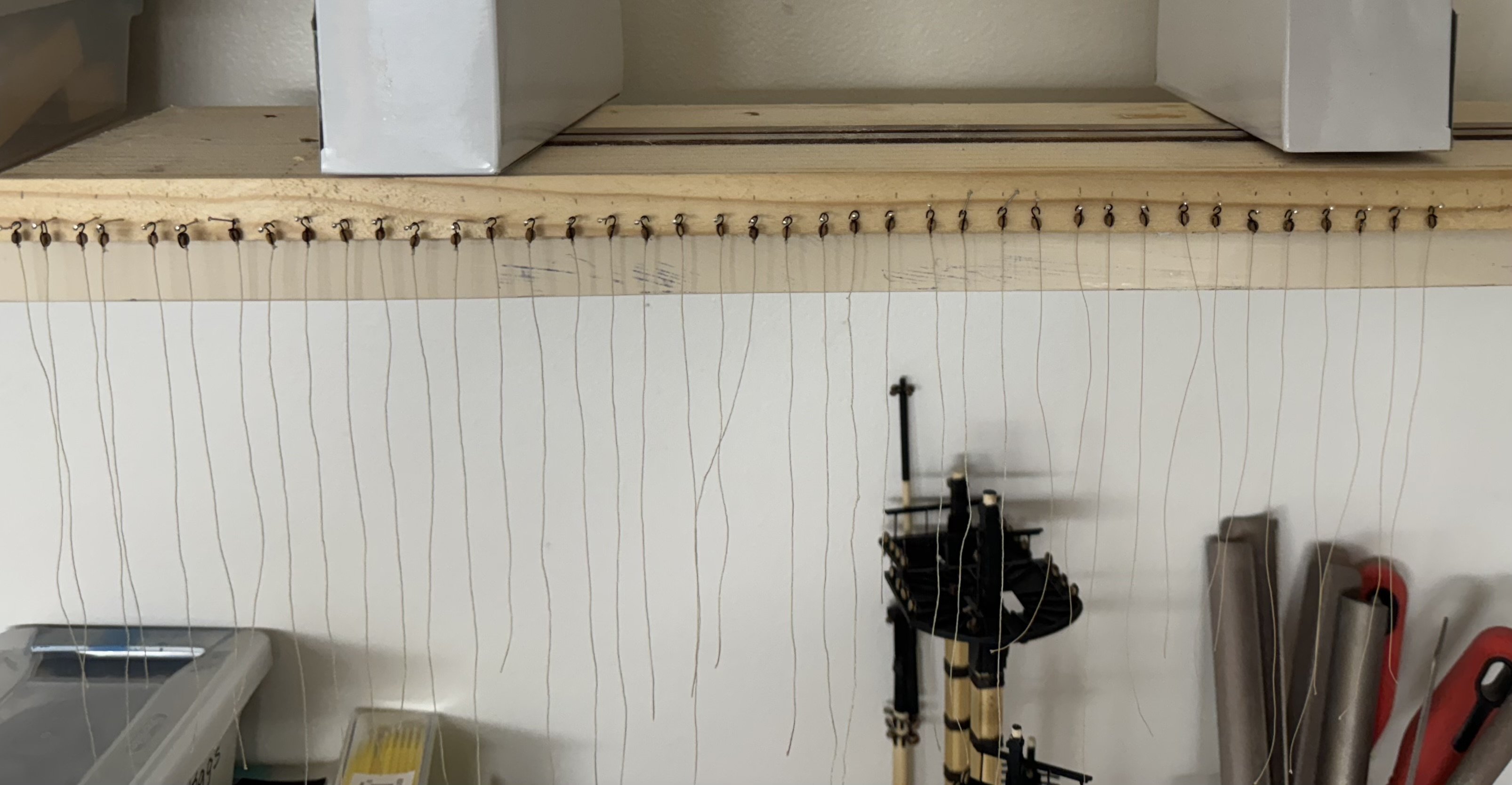
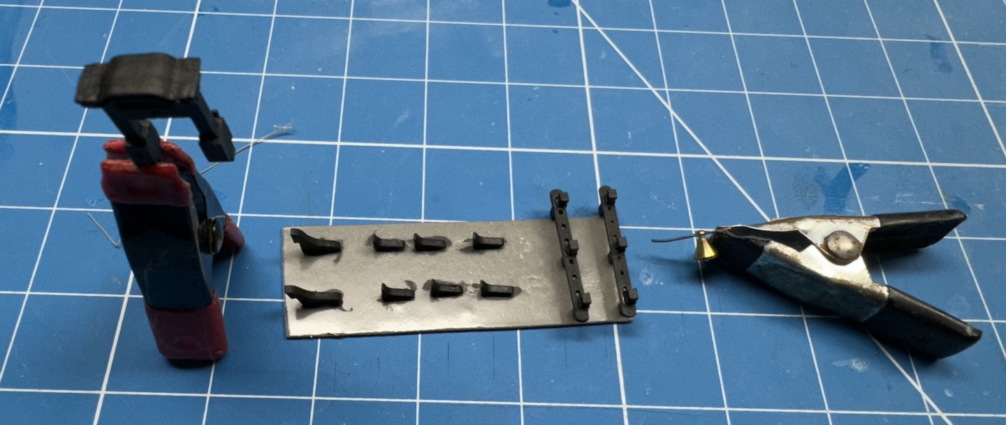
In between sand and fill cycles I have been working on the gun carriage tackles. I am going to rig only the recoil and run-in/out tackle. So I need 40 sets of tackle. I decided to use 3mm as that is about as small as I can figure out how to strop and get a hook on the end. Here are the 40 blocks with becket and the line attached. There are 10 more "in production" as it would be a rare occurrence if I managed to get all 40 in place without mishap. I used ,3mm tan line from Ships of Scale. The other blocks are ready to go as well so all I need now is a deck to mount them on.

- 422 replies
-
- 7
-
-

-
- Vanguard Models
- Sphinx
- (and 1 more)
-
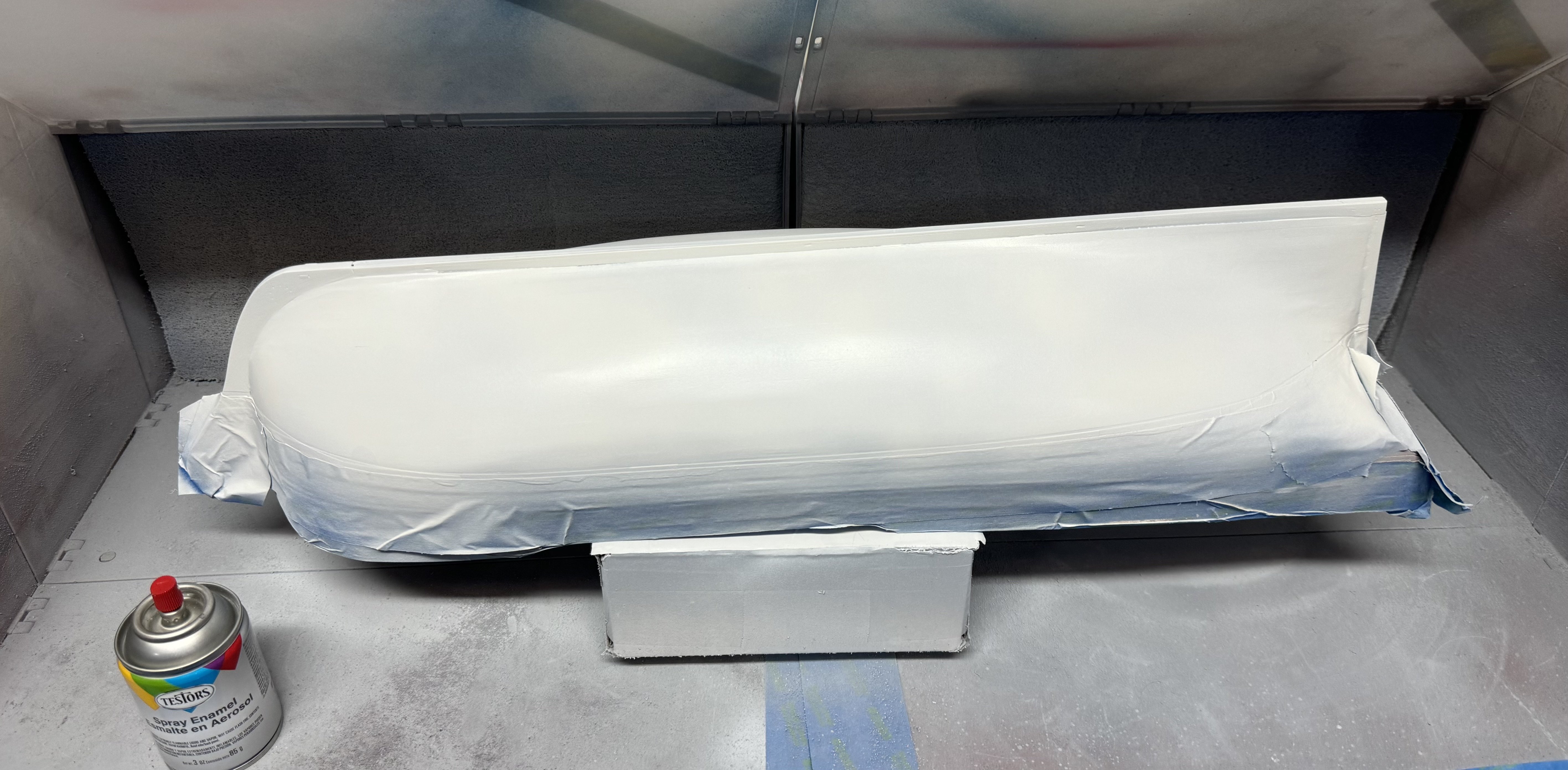
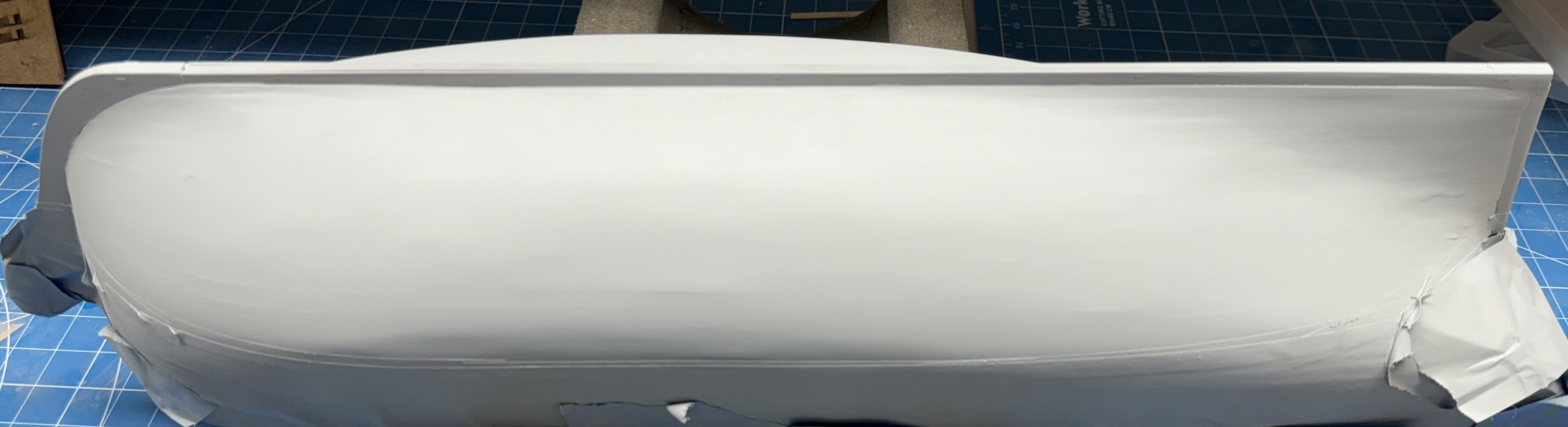
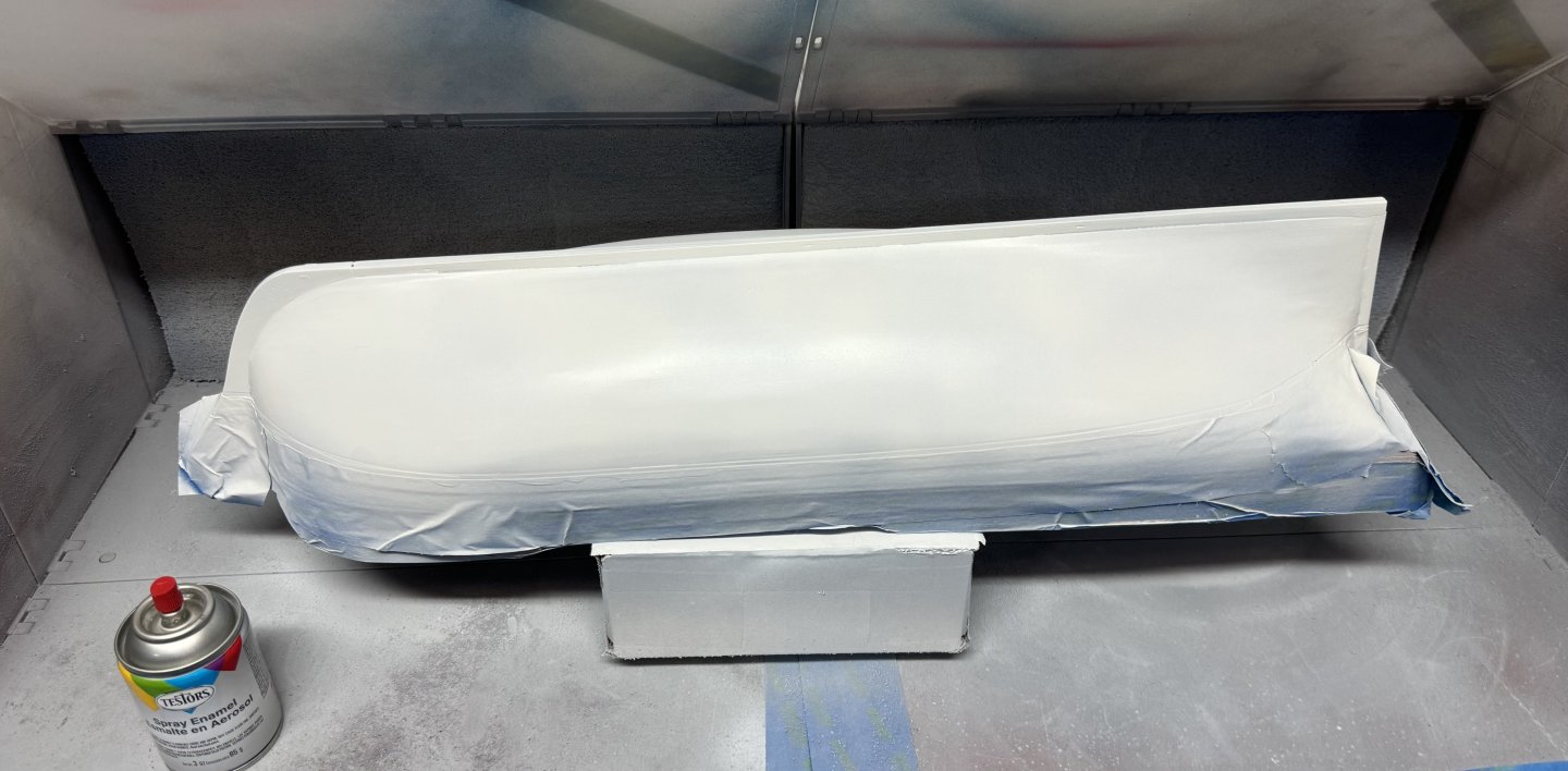
I added a bit more filler to the "stage 3" hull sanded and think that will "do it". In recognition of that I removed the masking that was just below the waterline and replaced it with masking at the waterline and carefully (I hope) fared the built up primer into the hull. Another coat of primer and on inspection and after some very limited 320 grit sanding I put the hull back min the paint booth for the finish coats of flat white. I am using Testors (aka Rust-oleum) spray paint (3 oz can) as this seemed to work out well on Sphinx hull #1. Although it took forever and a day to dry.
- 422 replies
-
- 6
-
-
- Vanguard Models
- Sphinx
- (and 1 more)
-
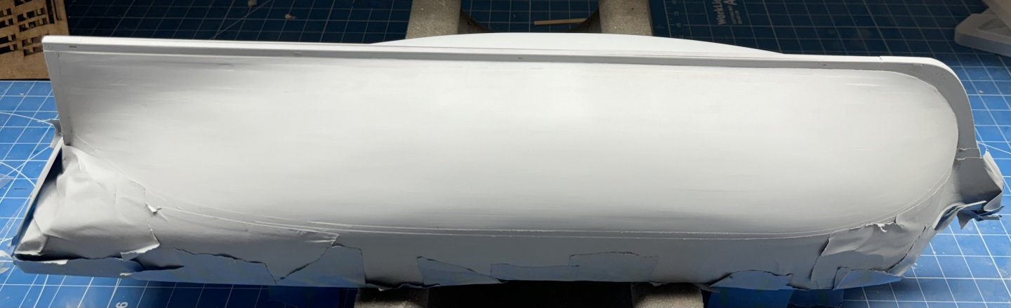
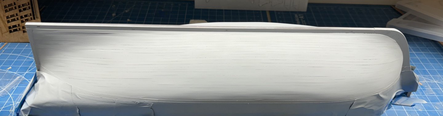
Round three shows much improvement but at least one more round required.

- 422 replies
-
- 7
-
-
- Vanguard Models
- Sphinx
- (and 1 more)
-
Thanks James I think it was 4 rounds on my first Sphinx hull before I started with the finish (aka flat white) paint. One thing I will do when I get to Indy is run all the planking material through my thickness sander to reduce as much as my tools will allow thickness variations in the planking material.
-
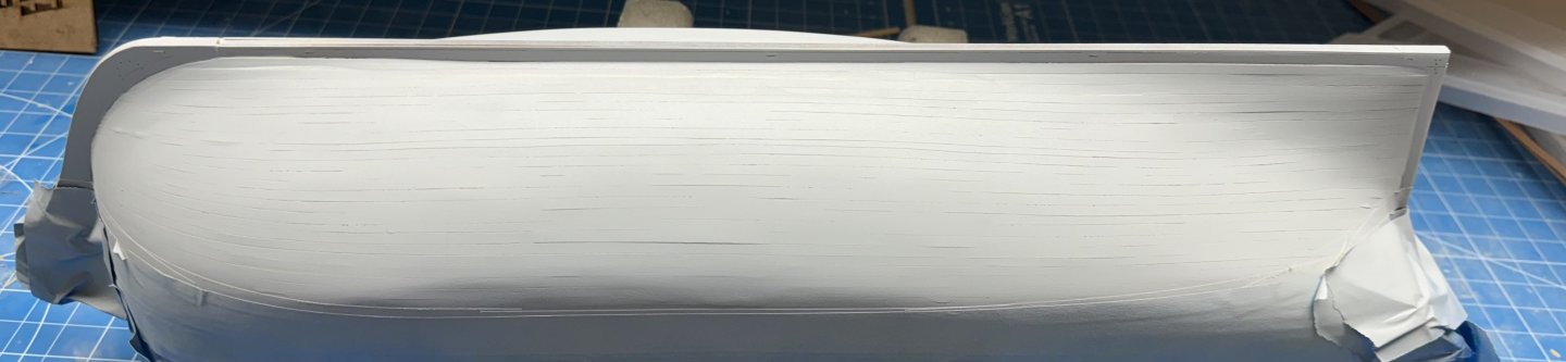
After the second application of thinned filler and subsequent sanding. I think I can see very narrow bands of white here and there which hopefully represent the filling of some of the small "cracks" that were so obviously present after the primer application. Back to the paint booth now to see what needs further attention.
- 422 replies
-
- 5
-
-
- Vanguard Models
- Sphinx
- (and 1 more)
-
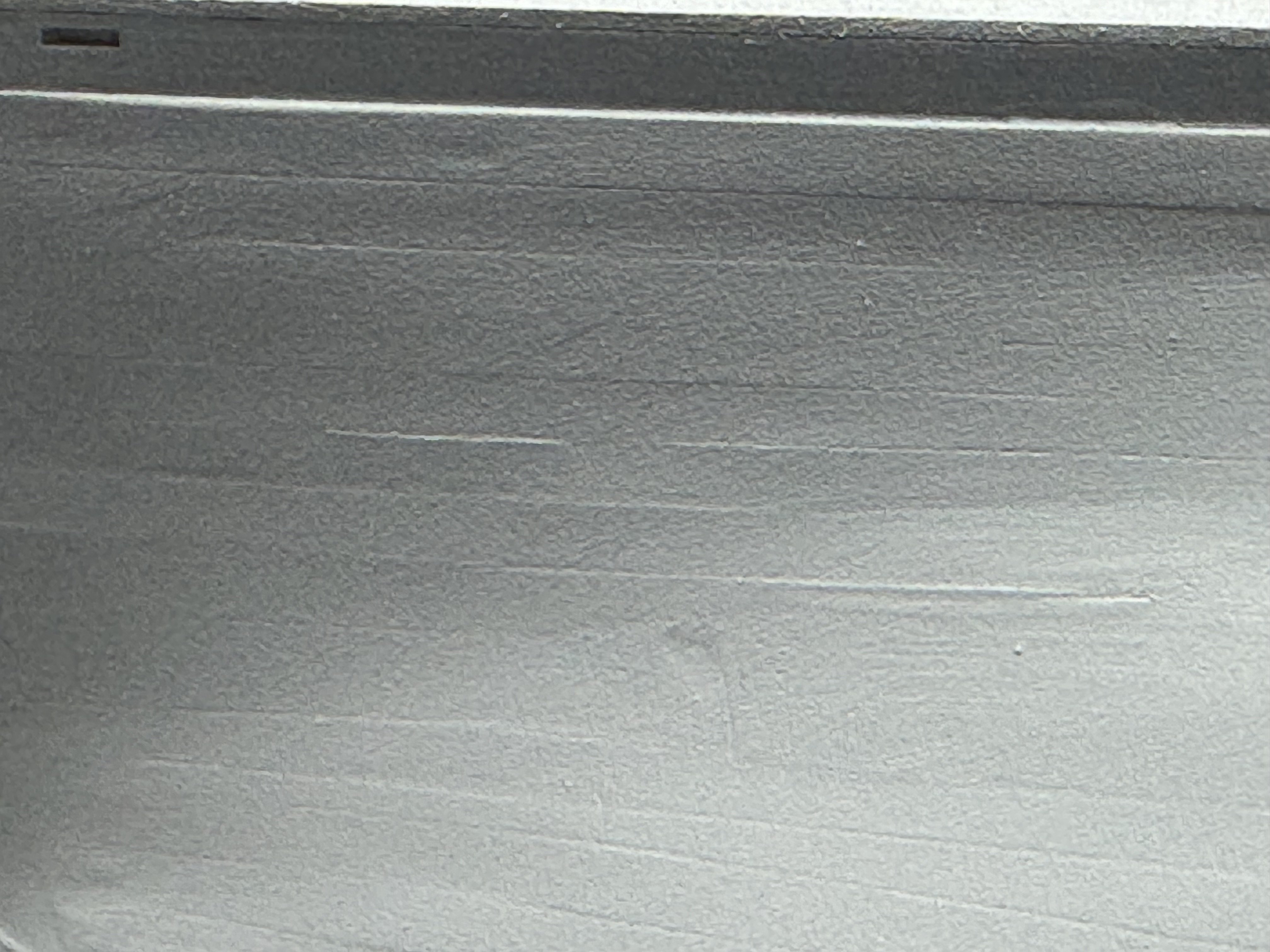
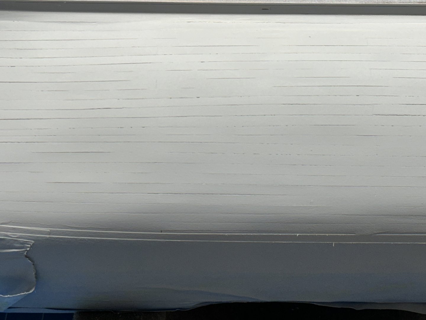
A somewhat disappointing trip to the paint booth. It looks like I can see every seam now. Maybe the moisture or something in the paint causes the seams to "appear" but this certainly is not what I expected. I am going to dilute the filler a bit more and try again.
- 422 replies
-
- 3
-
-
- Vanguard Models
- Sphinx
- (and 1 more)
-
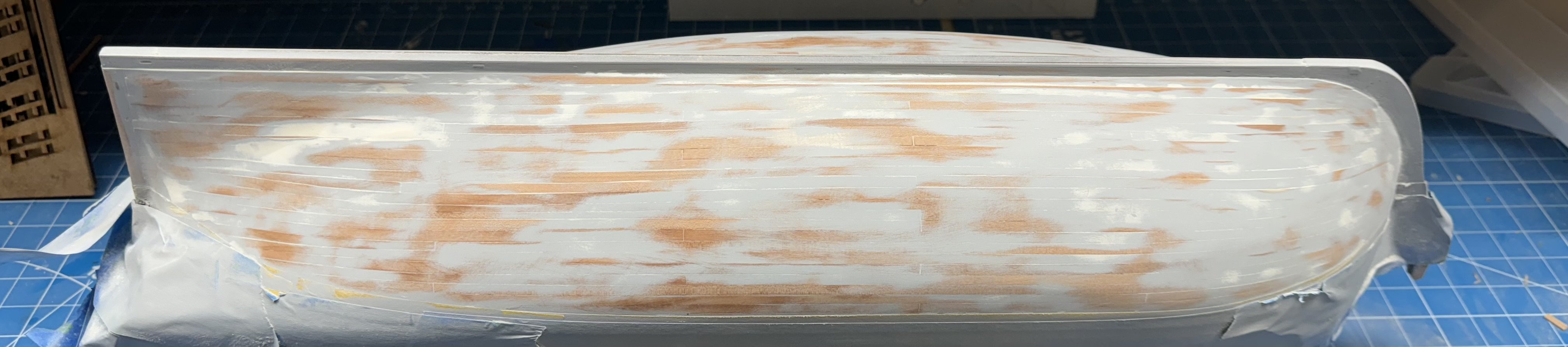
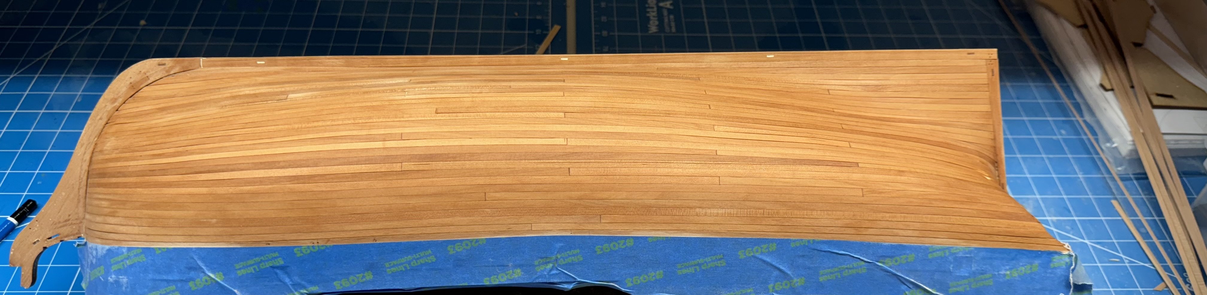
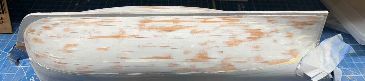
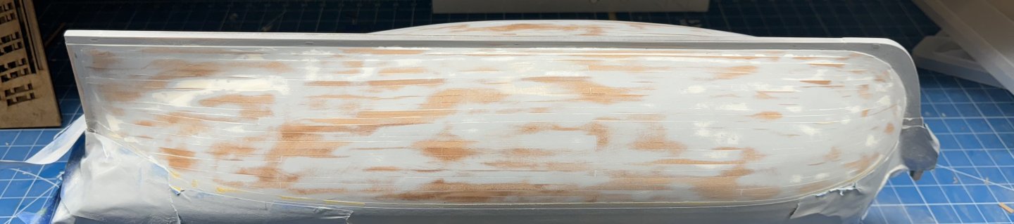
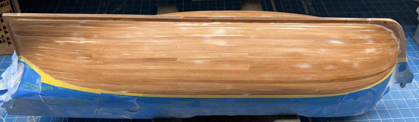
Here are the two sides after the first round of fill and sand. And yes I just wiped them down with mineral spirits. Not too terrible IMHO. Better than my previous Sphinx second planking (see post 136) - lots more white showing in those pictures. I am going to let the mineral spirits dry and then put the hull in the paint booth and use the automotive gray primer with filler and hope that it will identify the areas that need more work and keep the fill and sand to only two cycles (I think I did it four times on the previous hull).
- 422 replies
-
- 7
-
-
- Vanguard Models
- Sphinx
- (and 1 more)
-
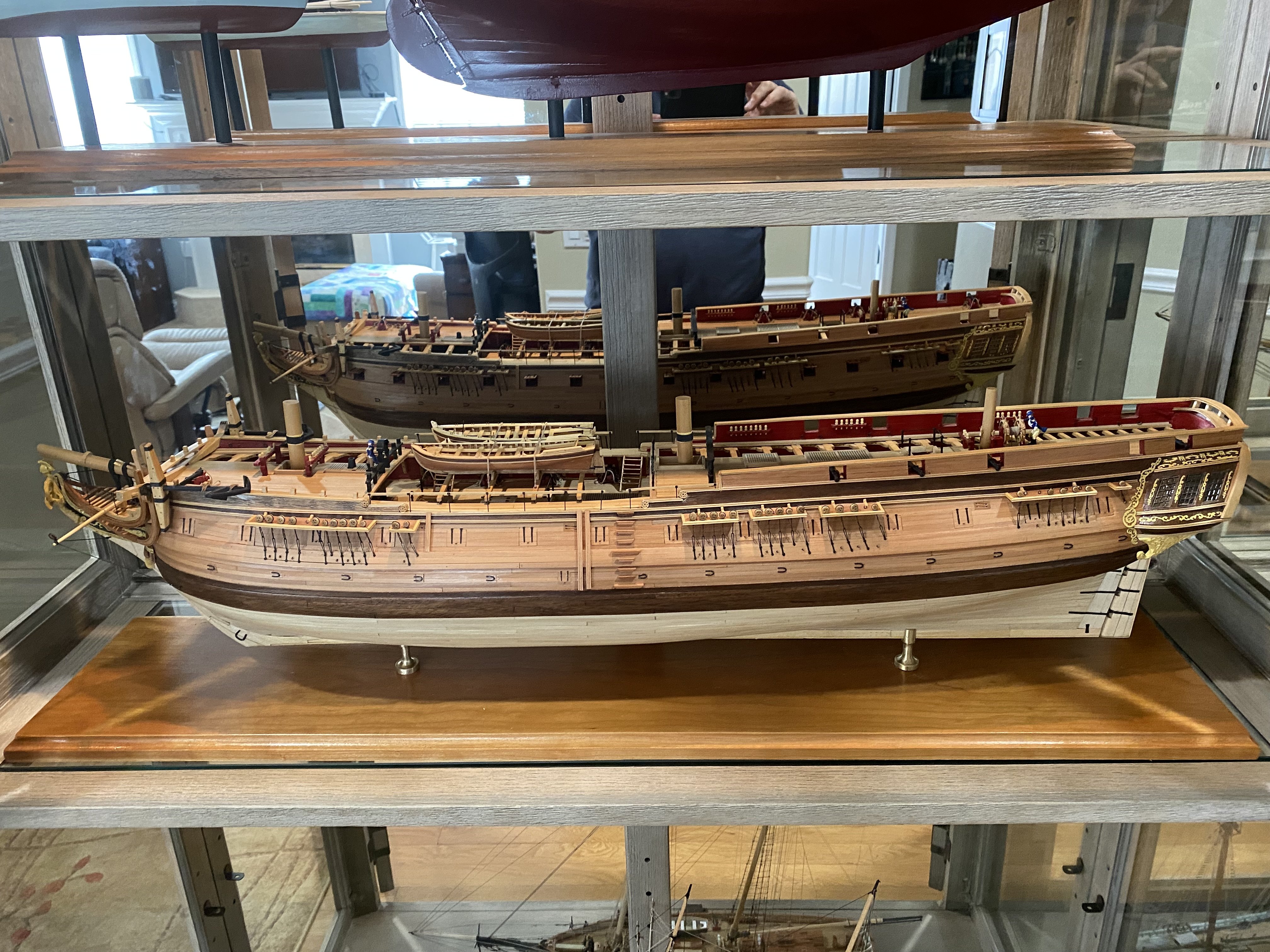
Thanks Ronald - yes, sadly painting or otherwise (copper) covering the hull seems to be the way on all the Vanguard kits. Historical accuracy IS important but as the builder it is our right to do "as we see fit" in these matters. On my Confederacy I used holly for the hull planking to get the lighter "look" without paint. I used walnut on the wales so I did not have to paint them either.
- 422 replies
-
- 6
-
-
-
- Vanguard Models
- Sphinx
- (and 1 more)
-
Yes Brunnels it always looks best when wiped with mineral spirits. The dull pear looks pretty bland and it shows all the "issues" much better. Hence I show in after the wipe down.
- 422 replies
-
- 1
-
-
- Vanguard Models
- Sphinx
- (and 1 more)
-
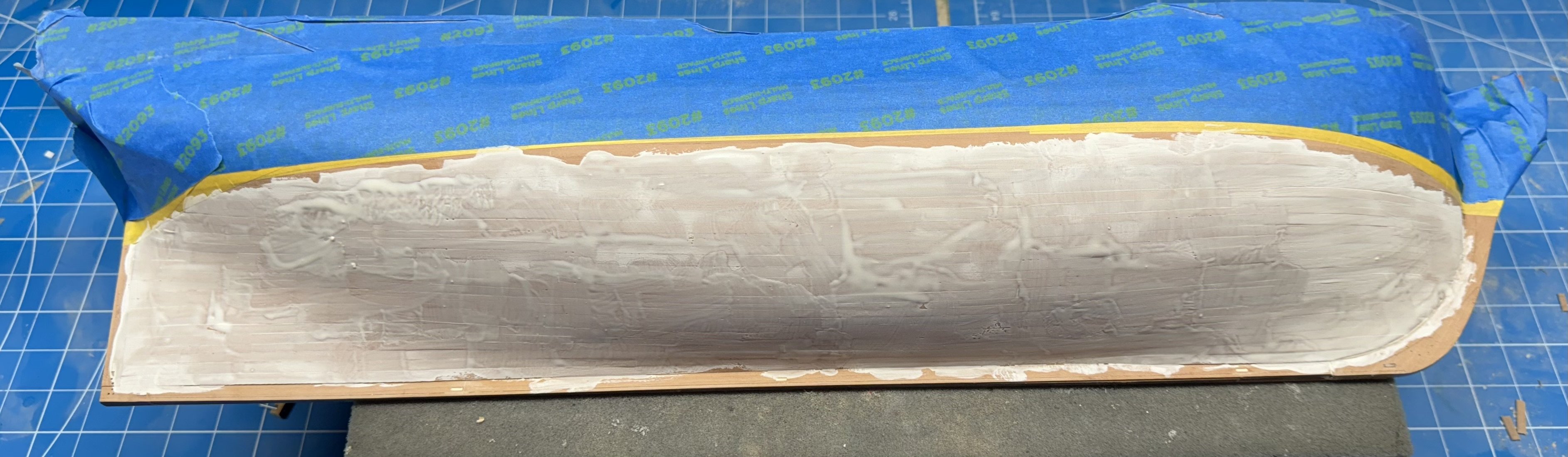
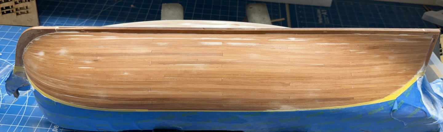
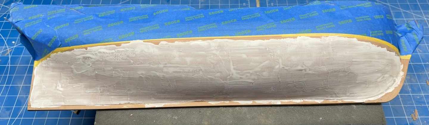
Waterline marked and masked off. First coat of thinned filler on starboard side.
- 422 replies
-
- 3
-
-
- Vanguard Models
- Sphinx
- (and 1 more)
-
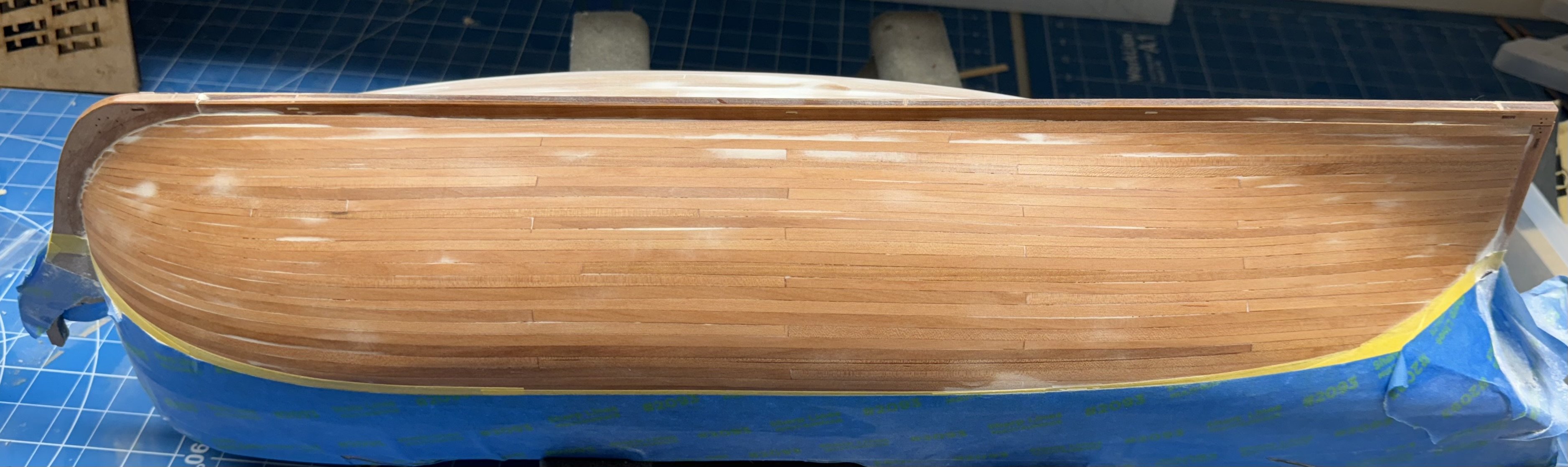
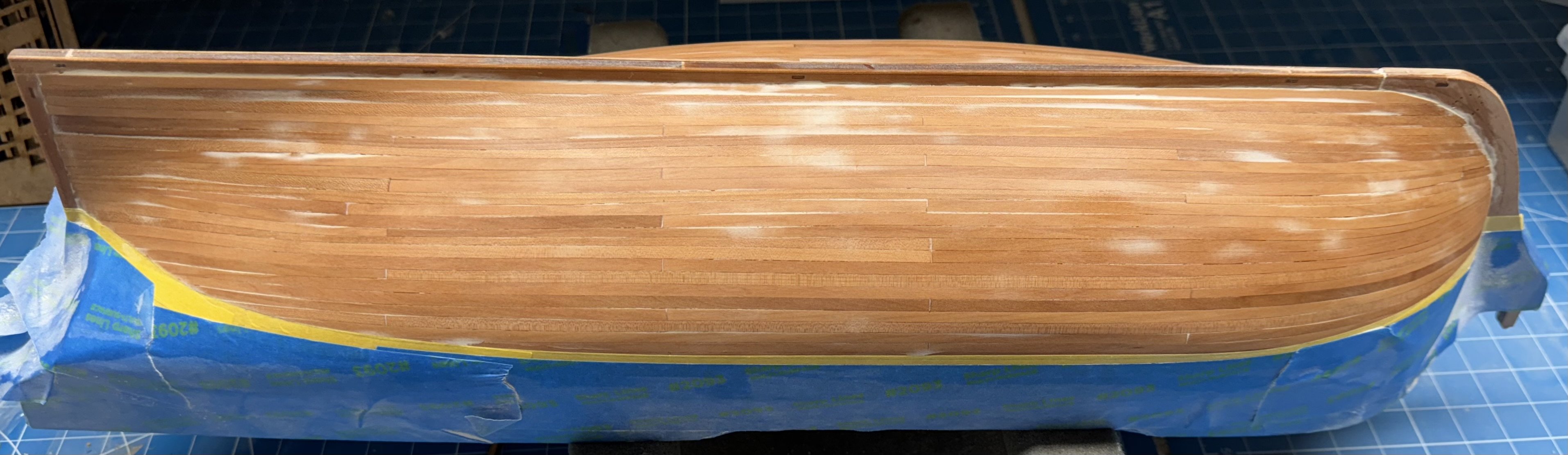
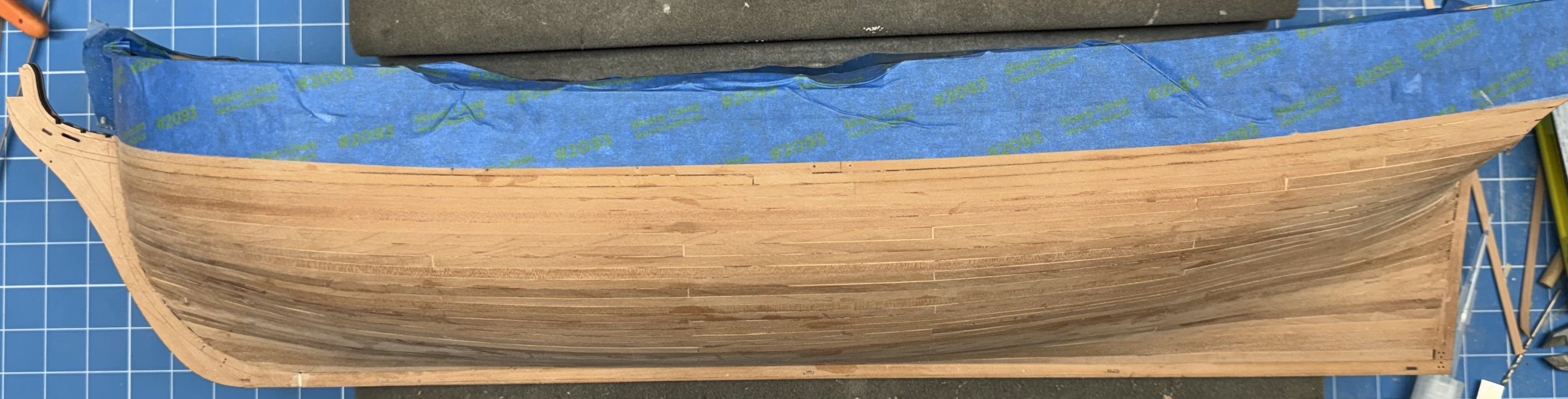
Thanks Ronald. And now both sides planked, sanded and wiped down with mineral spirits. Next is to mark the waterline and start with a thin coat of filler below the waterline and some "extra care" in those areas that will "show". I do have some Minwax Golden Oak wood filler which is a pretty close match to the supplied pear. It may come down to that but only as a last resort.

- 422 replies
-
- 7
-
-
-
- Vanguard Models
- Sphinx
- (and 1 more)
-
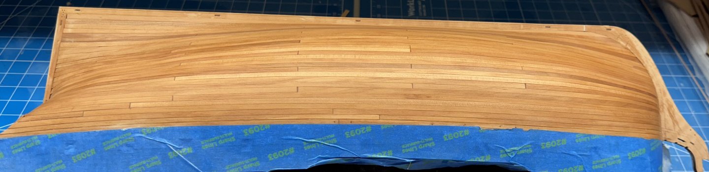
Port side planking completed. Had to split the last row into three pieces but was able to follow my plank butt scheme pretty faithfully otherwise. Not that it will matter since almost all of them are under paint.

- 422 replies
-
- 6
-
-
- Vanguard Models
- Sphinx
- (and 1 more)
-
Certainly something to plan on for Indy. I need to get the second layer of planking done on the hull before I get sidetracked.
-
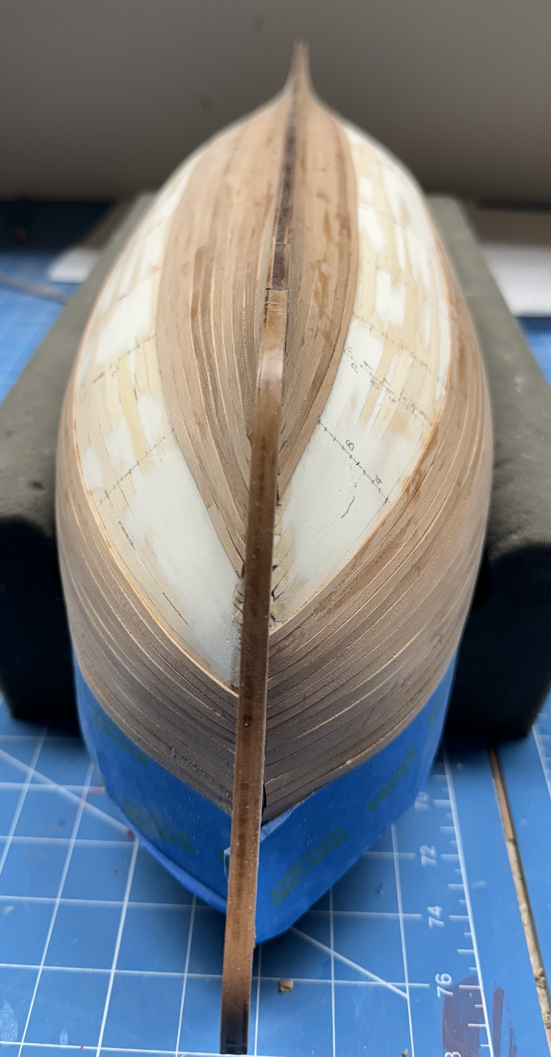
Ronald - ,I think you have it backwards; I need her ironing tool to support the shipbuilding. Amazon is bring me the shipbuilding iron on Monday but I have hers back until then. Worked on both sides today - have ten rows to go on each side although not the same ones as you can see below.


- 422 replies
-
- 5
-
-
- Vanguard Models
- Sphinx
- (and 1 more)
-
I had not thought about painting the inside of the great cabin. It looks much better (IMHO) than the "natural" that was what I did on Wincheslea and Confederacy. Something to consider for Indy as I am probably too far along on Sphinx.
-
Very, very nice work. I wish mine looked this good unsanded.