Supplies of the Ship Modeler's Handbook are running out. Get your copy NOW before they are gone! Click on photo to order.
×


cdrusn89
-
Posts
1,915 -
Joined
-
Last visited
Content Type
Profiles
Forums
Gallery
Events
Everything posted by cdrusn89
-
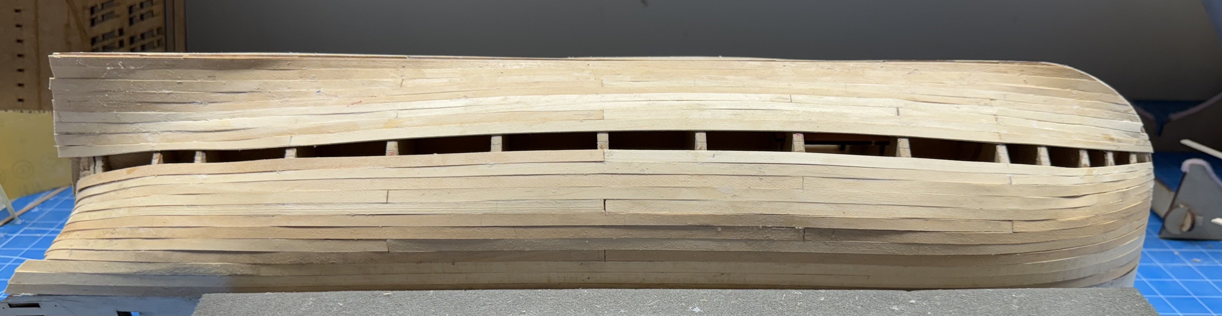
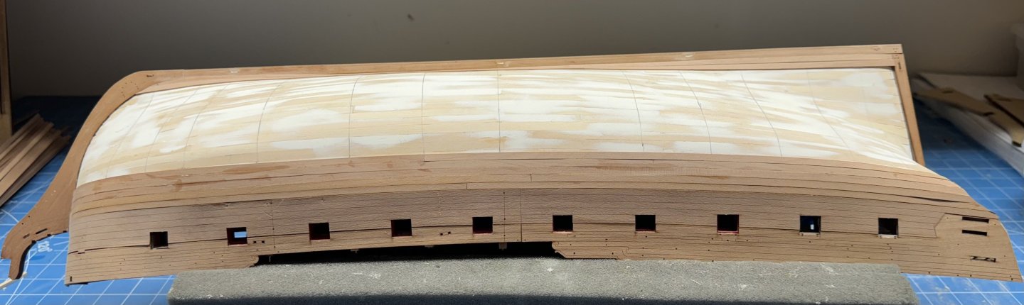
 Girlfriend needed the iron today so I could only work the keel side of the port side. I use the iron to bend the planks as they go over the stern. So here is the port side with 8 additional rows added - 16 to go on this side, 12 on the starboard side.
- 422 replies
-
- 6
-

-
- Vanguard Models
- Sphinx
- (and 1 more)
-
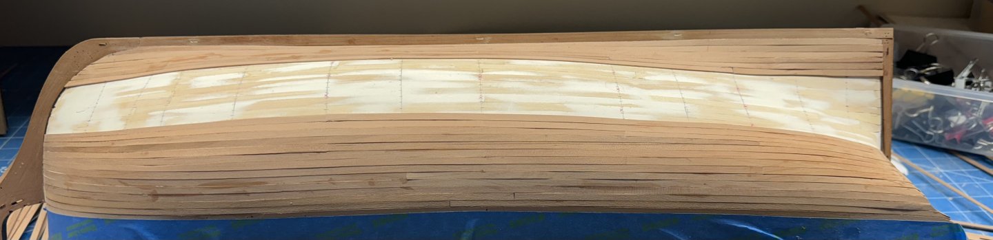
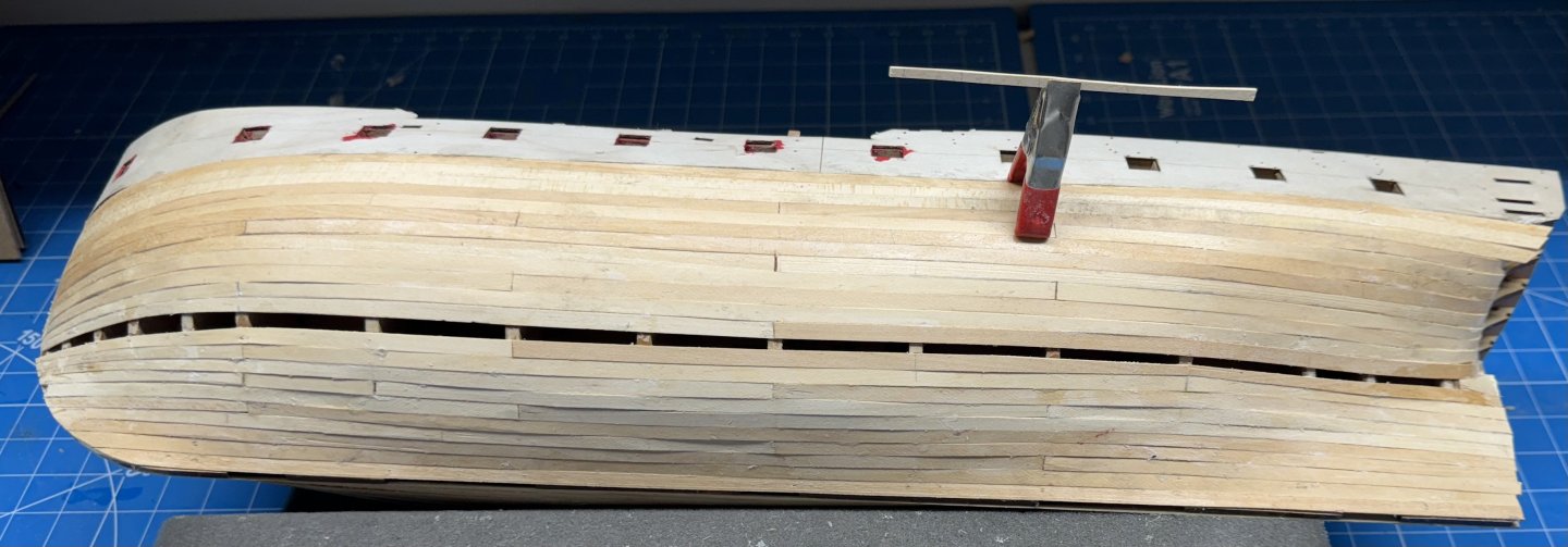
I got carried away on the starboard side and am now half finished: 12 of 24 rows completed. It is going considerably better than the first layer but I have to keep reminding myself that this layer "shows" at least some of it REALLY shows. I did not neglect the port side completely I did get it line off and plank butts marked. Tomorrow is "port side day".
- 422 replies
-
- 8
-
-
- Vanguard Models
- Sphinx
- (and 1 more)
-
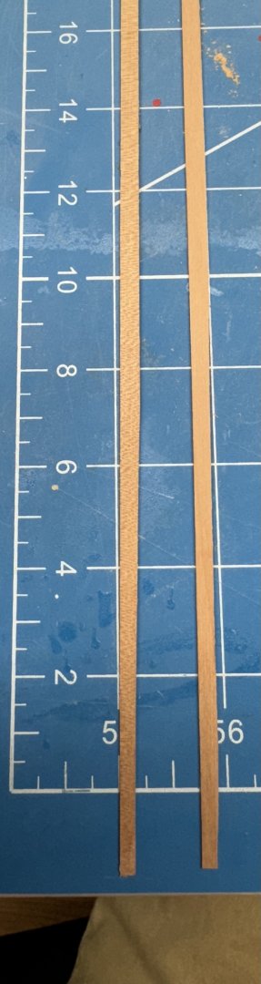
On to the second layer of planking. Before I lined off the hull I measured what I thought was a representative sample of the pear planks and used that measurement 4.0mm + or - .06mm) to get the number of required planks. Turns out my representative sample wasn't all that representative as I have since found 10 (so far) that are more like 3.85mm + or - .08mm. If they were all like that I would need more than 25 planks to cover the hull. I also found at least two that are decidedly (like 1mm) narrower at one end than the other. So I am in the process of separating (as best I can) the 4mm planks from the 3.8mm ones (and of course the ones that narrow at one end). I started planking the starboard side with the 4mm planks and I need to find enough (hopefully) to finish that side and then I will line off the port side using 3.8mm as the nominal plank width assuming the planks are more or less evenly split between the two widths. The moral of the story is to use the same plank width for each row - you want them the same width where they join. In any event here is the starboard side with four more rows of sheer planks installed.

- 422 replies
-
- 6
-
-
- Vanguard Models
- Sphinx
- (and 1 more)
-
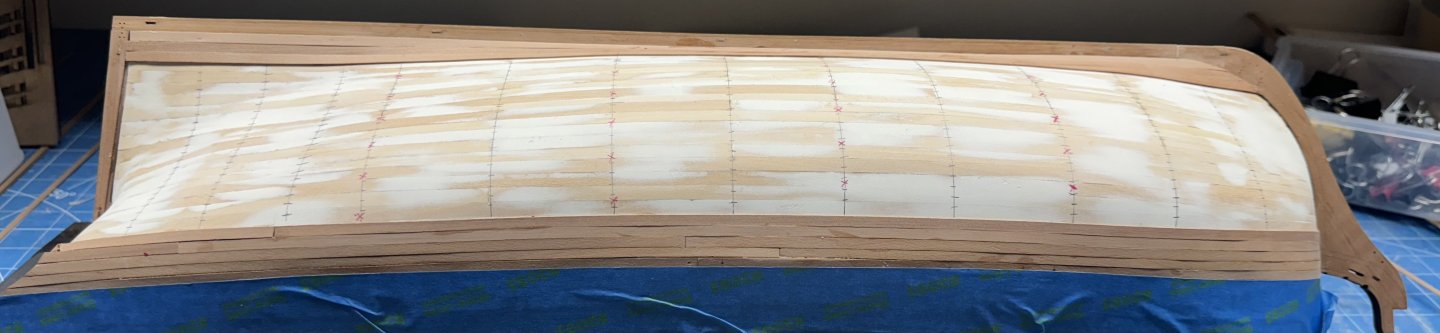
Starboard side lined off and plank butt pattern established (red "x"). Probably overkill but since it makes it easier at the ends to have the joints they might as well have some "order".

- 422 replies
-
- 2
-
-
- Vanguard Models
- Sphinx
- (and 1 more)
-
Thanks - JFM - It is somewhat easier the second time around. Best laid plans and all that. I thought that two sheer planks and one garboard would "do" but when I measured it was 100mm at the widest point and the pear planks are only 4mm wide (first layer was 5mm) so it would take 25 planks to cover the hull. Unfortunately my planking fan is only good for a max of 24 planks so I added one more, full width at the sheer and garboard and now can proceed to line off the starboard side.
- 422 replies
-
- 2
-
-
- Vanguard Models
- Sphinx
- (and 1 more)
-
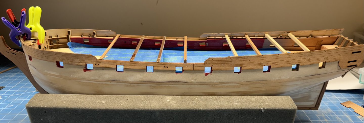
I added two full length, un-tapered planks at the wales similar to what was done on the first layer but only two rows as the starting point is further down the hull. Then I soaked both ends of two slightly shortened planks and clamped them on each side. These will become the garboard strake and then I plan on laying out the hull similarly to what was done on the first layer. Probably overkill. First task is to establish the bulkhead locations but that should not be too hard as most of them are still visible at deck level.

- 422 replies
-
- 5
-
-
- Vanguard Models
- Sphinx
- (and 1 more)
-
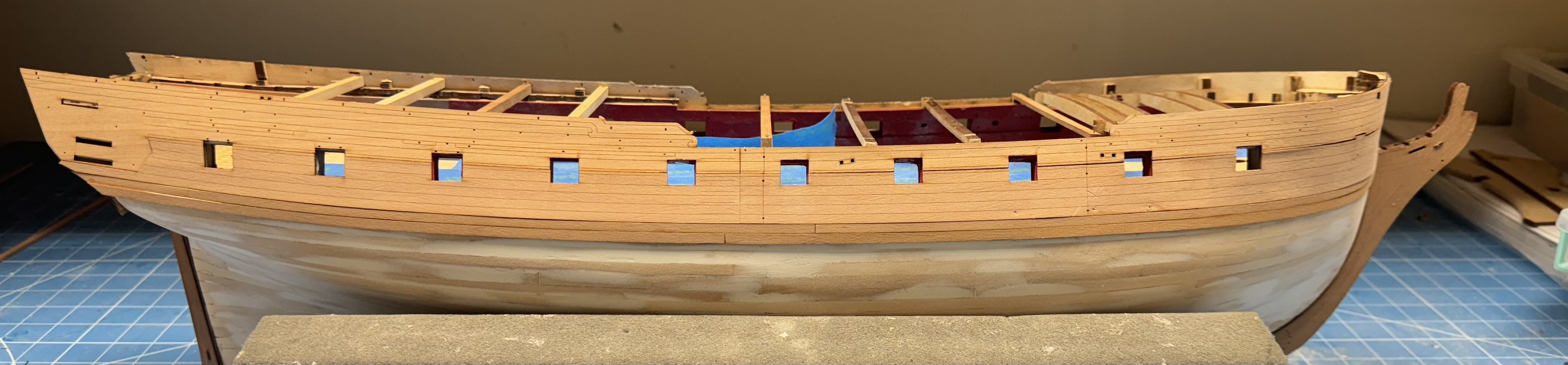
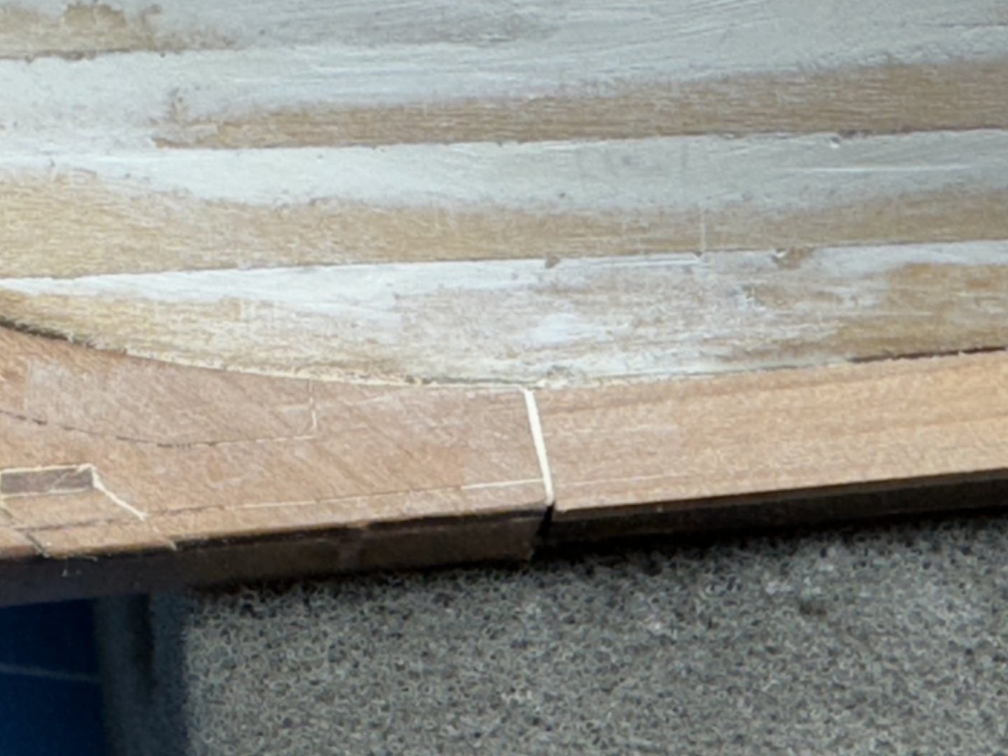
After I added the outer patterns to the stem and keel it became obvious that there was a small gap between - wide enough that paint was not going to hide it so I added some filler (on both sides) and since this area will be painted I hope the gap may disappear. So the next step is the outer counter "pattern". And it is thin enough that there is no need of soaking and shaping so it is just a matter of finding a way to clamp it to the inner pattern and "stick" to the curvature. I had to use four clamps and several rubber bands. The rubber bands (with pieces of sanding sticks under them) to get the upper (actually the lower with the hull upright) edges to match the lower pattern. You may notice that the entire counter is slightly offset to the right (in the picture). The offset is about 1mm wide and I am sure it is going to cause no end of problems later. In addition the counter upper (in the picture) corners stick out about 3mm from the hull. Once the second layer of planking is in place I assume these will be sanded down to match the hull curvature. Anyway, with the upper and lower external bulwarks and the first to rows of planking in place it is time to start the second layer of planking hoping for smoother results that the first layer. Here is my version of steps 180 and 181 in the instruction manual.

- 422 replies
-
- 7
-
-
- Vanguard Models
- Sphinx
- (and 1 more)
-
I got the upper outer bulwarks curved and glued on (mostly). When I started to fit the lower band I noticed that the lower part on each side right at the bow was not glued down so I added some more PVA and clamped them as best I could (you can see the clamps in the pictures) and will continue fitting the lower band when this is dry. I also managed to get the little tab that is part of the gun port door on the forward lower part on one side bent outward a bit so I re-wet that part and clamped it straight (hopefully) and will let that dry too - I only wet the part on both sides I did not soak it so (hopefully) I will not have to wait overnight again.
- 422 replies
-
- 7
-
-
- Vanguard Models
- Sphinx
- (and 1 more)
-
Looks really good. I have used automotive spray primer with filler in the past. It helps to visualize the areas that need attention plus fills in any really small cracks/flaws. Need to mask off above the waterline (obviously). I am right behind you. Have to add the transom/keel/stem/stern post etc. then on to the second layer.
-
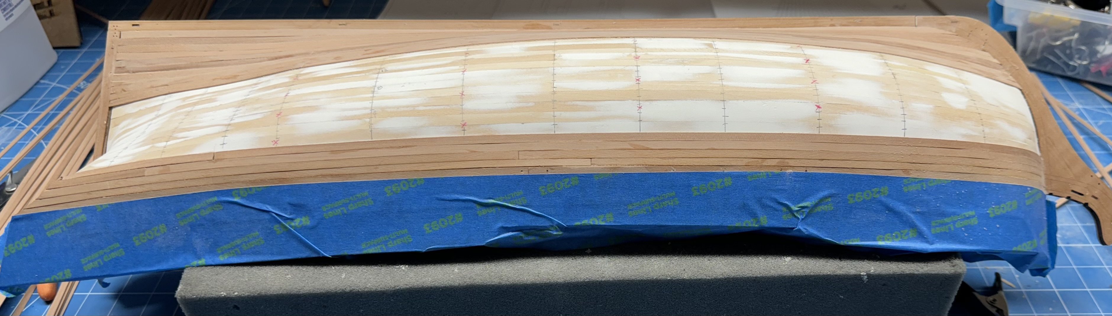
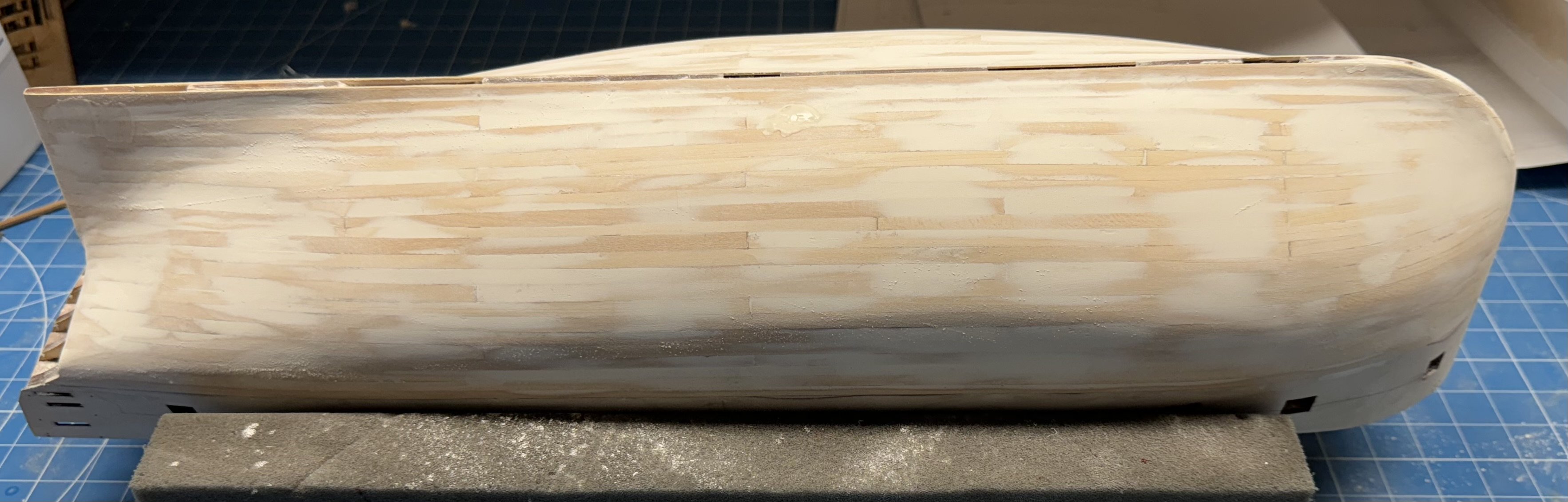
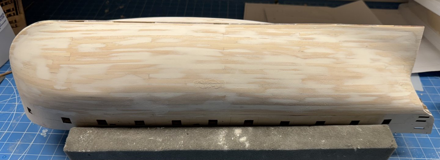
I have done two rounds of fill and sand using thinned "Goodfilla" filler and first 120 grit paper and then 220 and there are just a few areas that need a bit more attention and I will stick a fork in this and call it done. Given the amount of filler visible I guess I did not do as good a planking job as I thought (hoped?). However, I would rather look at the filler than sand through the planking trying to get it smooth. On the previous build of Sphinx I used automotive spray primer with filler after I thought I had the Goodfilla smooth. I decided to leave the automotive primer for the second layer (where it doesn't show) as i think this is smooth enough to host the second layer and I do not want the primer messing up glue adhesion and it is generally a messy process that I really only want to go through once.

- 422 replies
-
- 8
-
-
- Vanguard Models
- Sphinx
- (and 1 more)
-
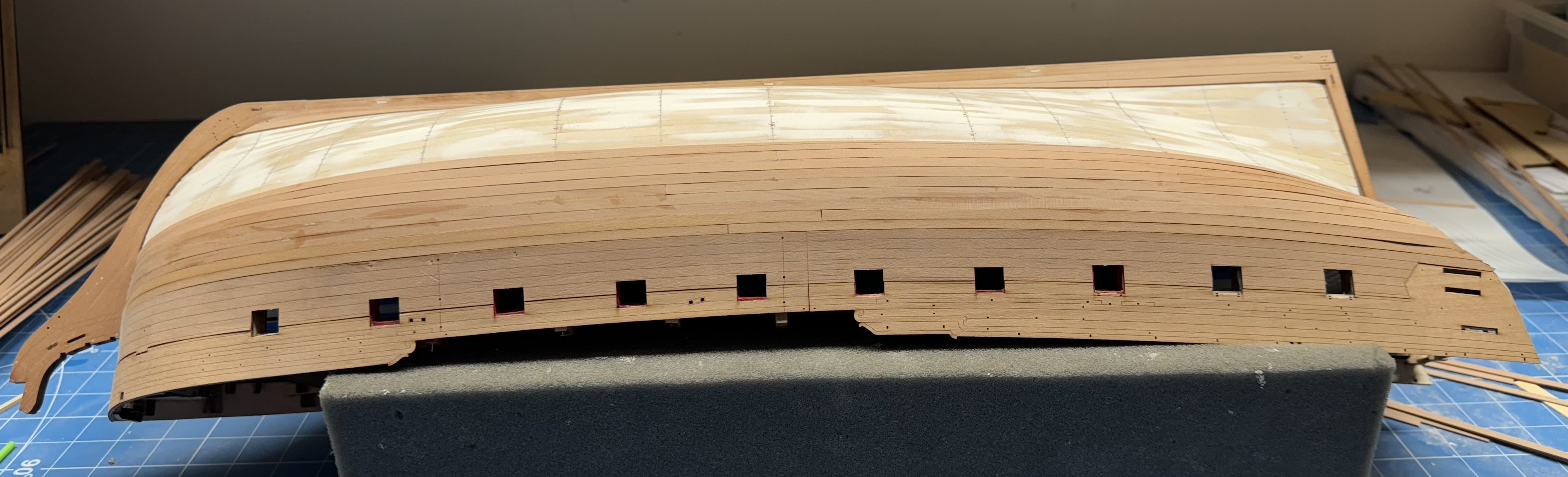
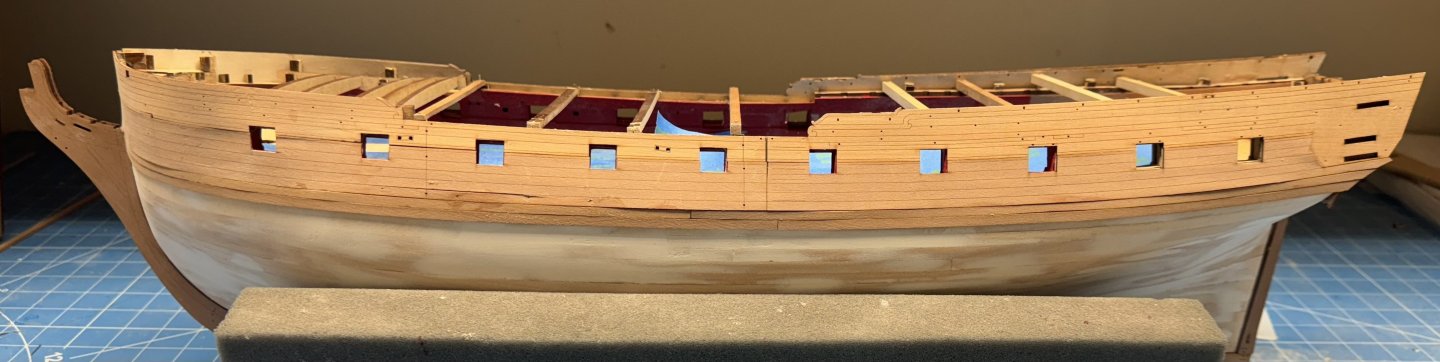
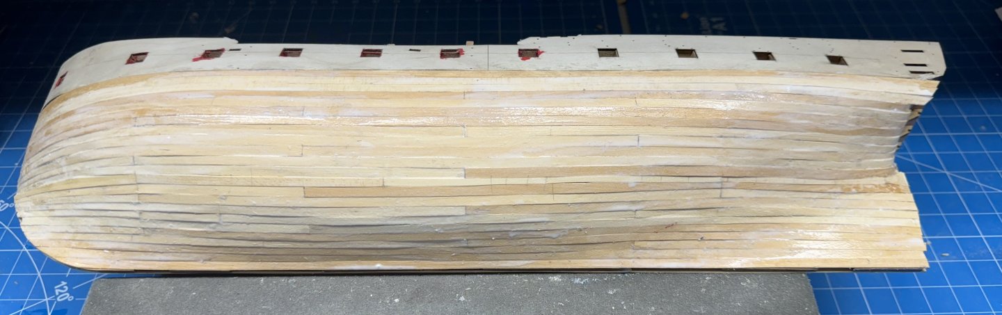
Thanks Mugje; yes and now the starboard side is completely planked and I can "raise some sawdust" - but not too much. Don't ask me how I know but you CAN sand all the way through 1mm planking. Here is the starboard side "resting" after being painted with 60/40 PVA/H2O.

- 422 replies
-
- 6
-
-
- Vanguard Models
- Sphinx
- (and 1 more)
-
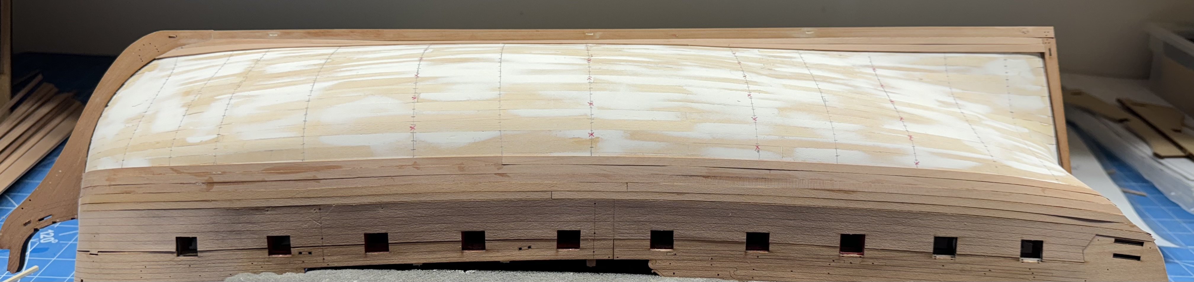
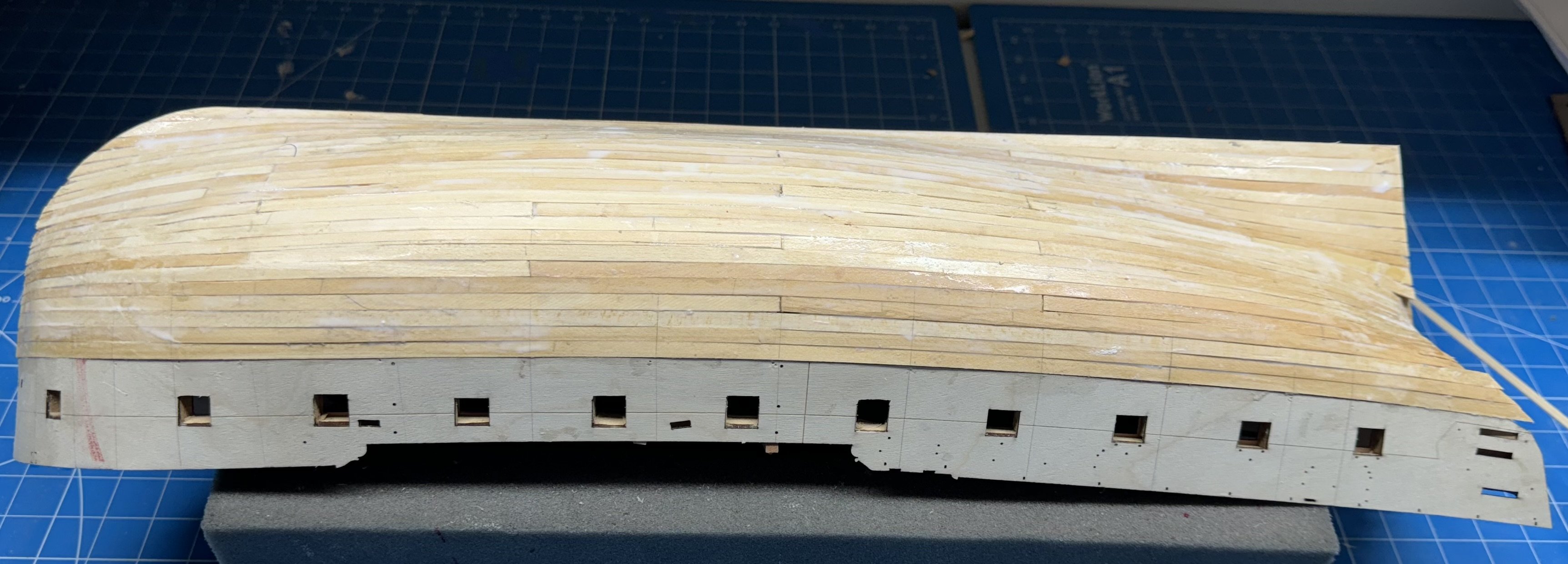
Port side fully planked (first layer). Breaking the last row up into four segments makes things go much faster than trying to get a single (or even two) segments to fit. I had to resort to a left over 7mm wide plank for the last segment at the bow. I could probably have forced a 5mm wide plank to fit but since I had the 7mm I used it - sort of like spieling. I also painted the entire side in 60/40 PVA/H2O to help insure the planks are glued together edge-wise as well as to the bulkheads. The bulkheads are far enough apart in places where if two planks can move relative to each other it will be difficult (if not impossible) to get filler (should it be necessary) to not crack every time I go over it with a sanding pad or stick. On to the starboard side where I have three rows left to plank.
- 422 replies
-
- 6
-
-
- Vanguard Models
- Sphinx
- (and 1 more)
-
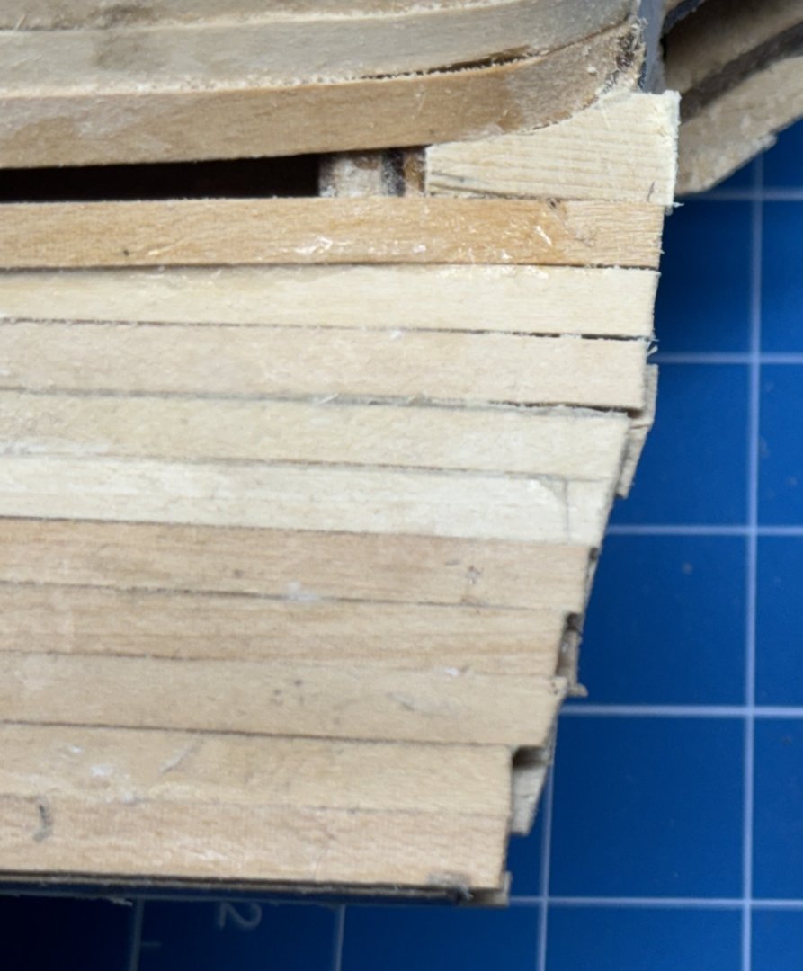
One row left on the port side. As you might imagine it is anything but a constant width from end to end. In fact I had to add a "stealer" at the stern and it is a somewhat abbreviated one as I had no desire to try and fashion a plank that was 12mm at one end and 2.5mm at the other. So I just did the first 17mm of it and glued it in. Given the somewhat sinuous character of the remaining plank space I am going to break it up into four segments. The first segment forward of the stealer is in the clamp. Working the rest of them - slow going as most are not monotonically narrowing or widening so it is sand and check fit, sand and check fit, rinse and repeat.
- 422 replies
-
- 3
-
-
- Vanguard Models
- Sphinx
- (and 1 more)
-
Port side with two rows to go. I checked and the last row will have to be tapered its entire length b ut that does not come as a complete surprise since the math worked out to 17.7 rows and I rounded to 18. Hope to get at least this side finished today - only four more rows on the starboard side so the end (of the first layer of planking) is "in sight"

- 422 replies
-
- 6
-
-
- Vanguard Models
- Sphinx
- (and 1 more)
-
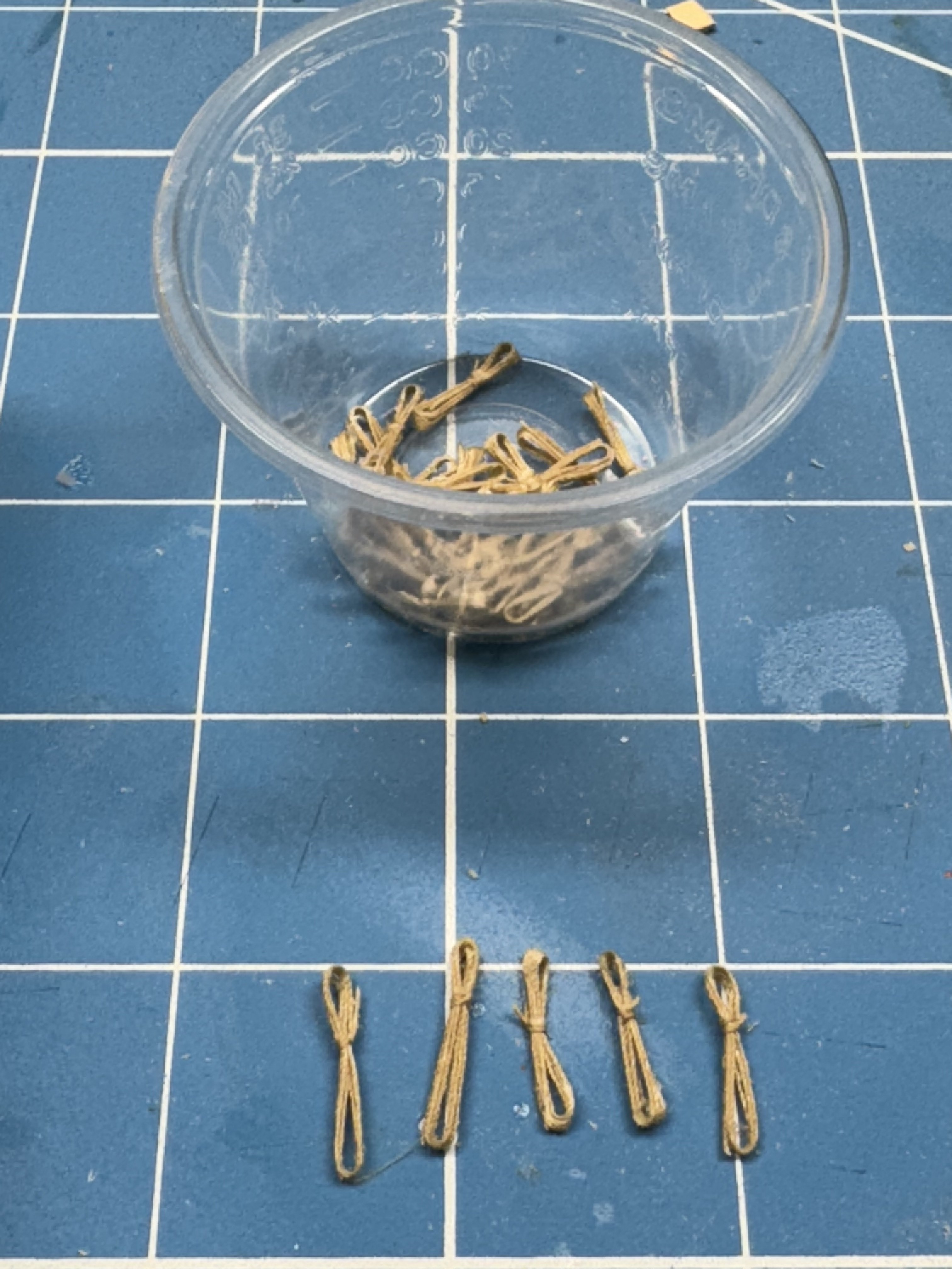
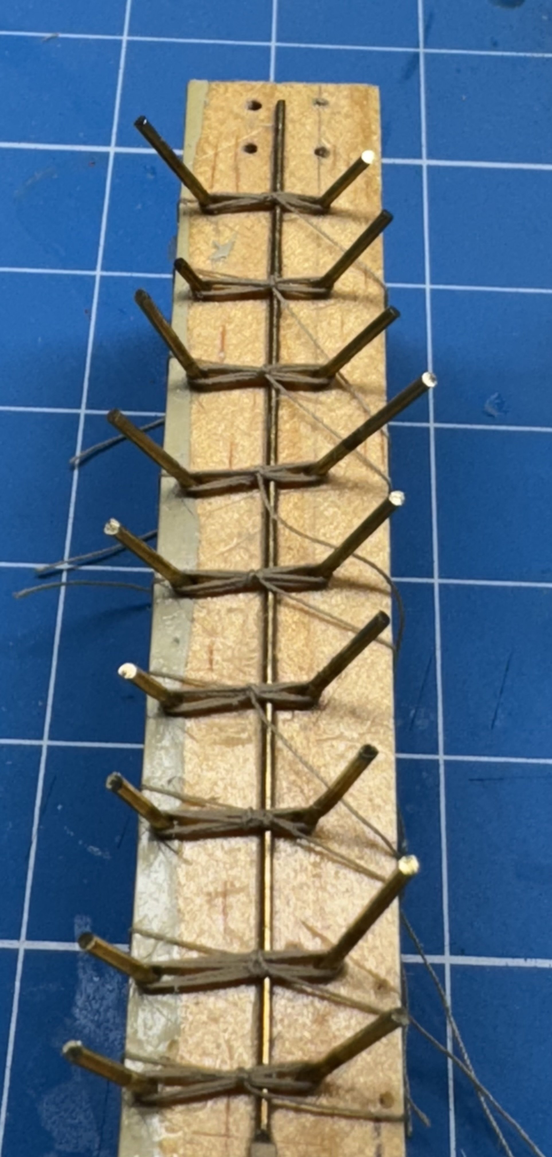
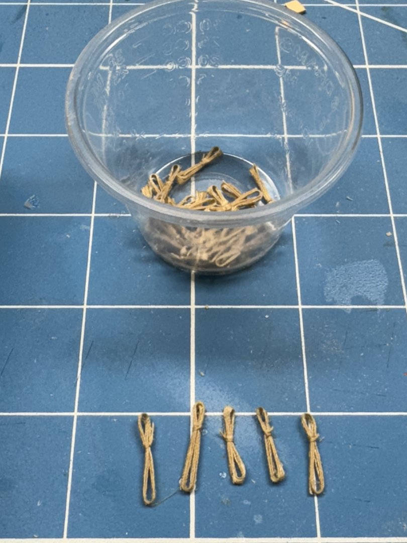
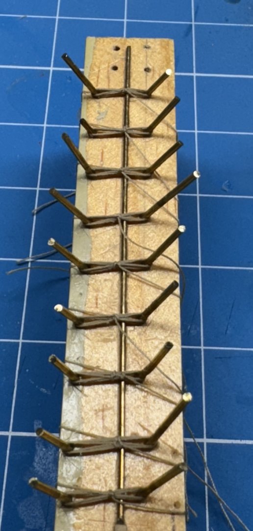
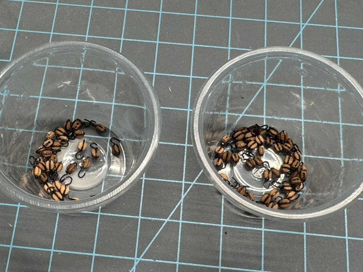
After a good deal of trepidation I decided to fully rig the Sphinx cannon. The "pre-made" cannon I have already have the breeching line in place ready to the adjusted to the correct length once the eyebolts are in place. It is the tackle used to pull the gun back into firing position after it is swabbed and loaded that I am going to add. I believe that the "train tackle" was not generally rigged unless it was needed - at 50 yards you just wait until you can see the other ship (amid all the powder smoke) and fire. I decided to use 3mm blocks for this although that is probably a bit oversize I find it very difficult (for me) to work anything smaller. The blocks are Model Expo "Beautiful Blocks" (MSBB1030 in case anyone wants some) stropped with 26ga "black wire" which is really copper painted black by the supplier (Artistic Wire). I built a little jig using steel pins to hold the block in place and used the groove in the block to "seat" the wire and used a drop of medium CA to glue the wire to the block and to itself where the two pieces cross. I also drilled out the holes in the blocks (#74 drill bit) to make sure I would not have an issue trying to thread the line though later. So, 20 cannon (actually 24 counting four on the quarterdeck) although to what extent they are rigged is TBD at the moment. So that means 44 sets of tackle with two blocks in each set or 88 3mm blocks, half with a becket for the standing end. Here is a good start but I am continuing production since any extra will probably come in handy on the next model on the shelf (Indefatigable). Part of the rationale for the wire stropping was so I could get a hook on each block - mine are over scale but the ones provided on the PE sheet are about the same size and getting them attached to the block is ... It is my understanding that the tackle was detached from the gun after it was in position and before it was fired so there would be hooks on at least the gun end of the tackle. So if I have 40+ tackle I need 40+ "rope coils" to terminate the tackle on deck (although I seriously doubt they left any lines on the deck when not it use as the decks were generally wet and wet line rots more quickly than dry). I am going to use Syren .008" Ultra tan line for the gun tackle. On my Niagara I made up coils of rope using double sided tape to make the coils. That experience made me decide on something faster. I built the jig below to make rope coils to hang on belaying pins on previous models. The brass rod down the middle provides a channel to thread the line under when you end the coil. I used five turns around the brass pins then a double overhand knot to finish off. Two coats of 60/40 PVA/H2O soaking up the excess after 30 seconds or so. Here are nine coils ready for removal. I am considering making a new jig with the "stations" further apart as I seem to have difficulty wrapping the line around just two of the brass pins, even with only the occupied pins in place. Here are enough coils to do the guns. Now I need more to hang on the shroud cleats and belay points elsewhere. I am going to reduce the number of turns around the pins to three and use both the Syren line and the 0.1mm line provided in the kit as I will need coils of both. The provided shroud cleats are pretty "narrow" (opening between base and horns) and three turns may be one too many - I will experiment "later".
- 422 replies
-
- 5
-
-
- Vanguard Models
- Sphinx
- (and 1 more)
-
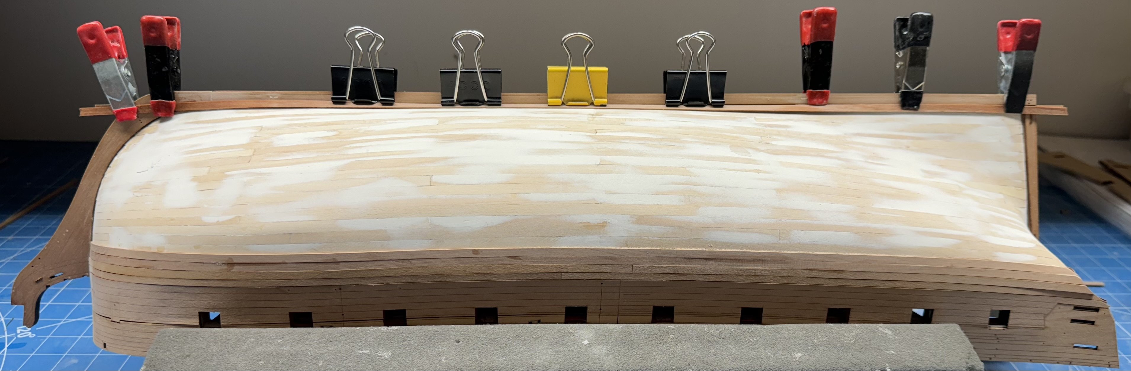
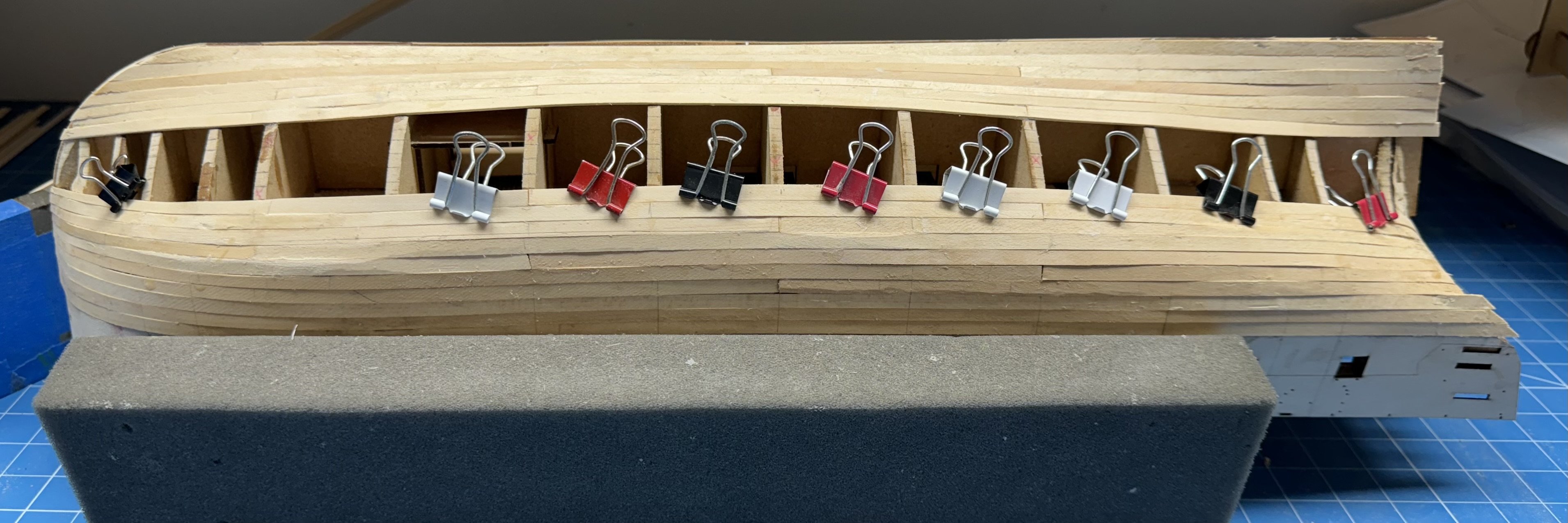
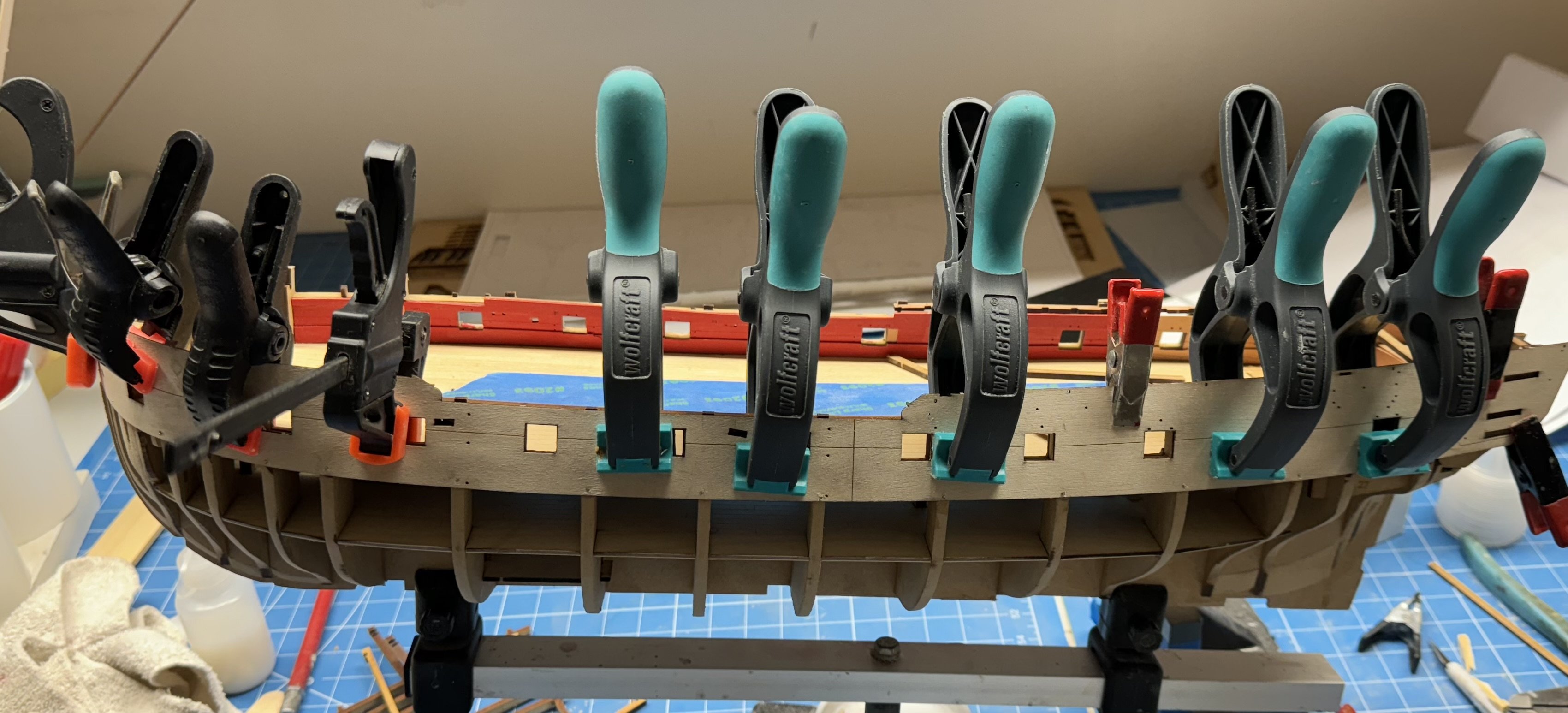
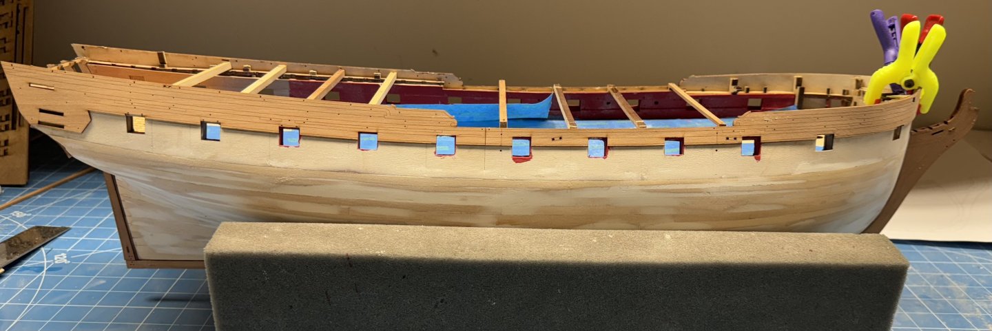
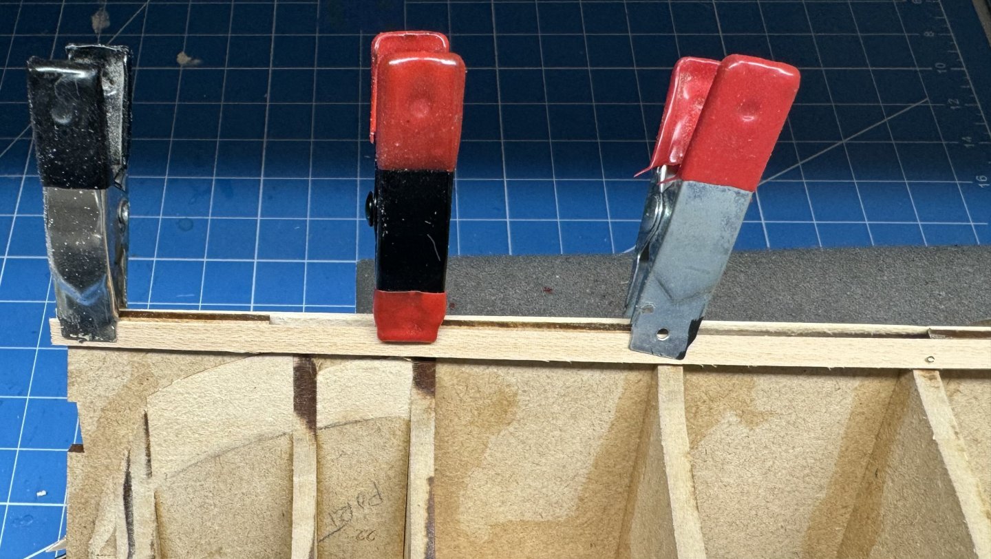
Starboard side 2/3rds complete 12 rows completed, 6 to go. Port side is in the same state so i will spare you the picture. Clips are used to keep planking "lined-up" as they have a tendency to want to bend in (or out) as the moisture in the PVA evaporates. Not sure what I am going to do in another row or two when these clips won't fit anymore. There is always filler 😀

- 422 replies
-
- 1
-
-
- Vanguard Models
- Sphinx
- (and 1 more)
-
Port side half finished Now the"real fun" as we close in on the "finish".

- 422 replies
-
- 5
-
-
- Vanguard Models
- Sphinx
- (and 1 more)
-
Starboard side half finished - 9 of 18 rows completed. On to the port side now. Although my memory of doing this on the first hull is somewhat hazy after looking at the pictures of that effort this seems to be progressing well.

- 422 replies
-
- 4
-
-
- Vanguard Models
- Sphinx
- (and 1 more)
-
Starboard side with five of 18 rows completed. I need to bend some more planks for the stern so I will attend to that and call it a day.
- 422 replies
-
- 2
-
-
- Vanguard Models
- Sphinx
- (and 1 more)
-
Port side lined off and five of the 18 additional planks in place. Back to the starboard side now. Doing four rows (two top, two bottom) on each side. Breaking off the bulkhead extensions does have the side benefit of making moving the hull around while planking easier.
- 422 replies
-
- 1
-
-
- Vanguard Models
- Sphinx
- (and 1 more)
-
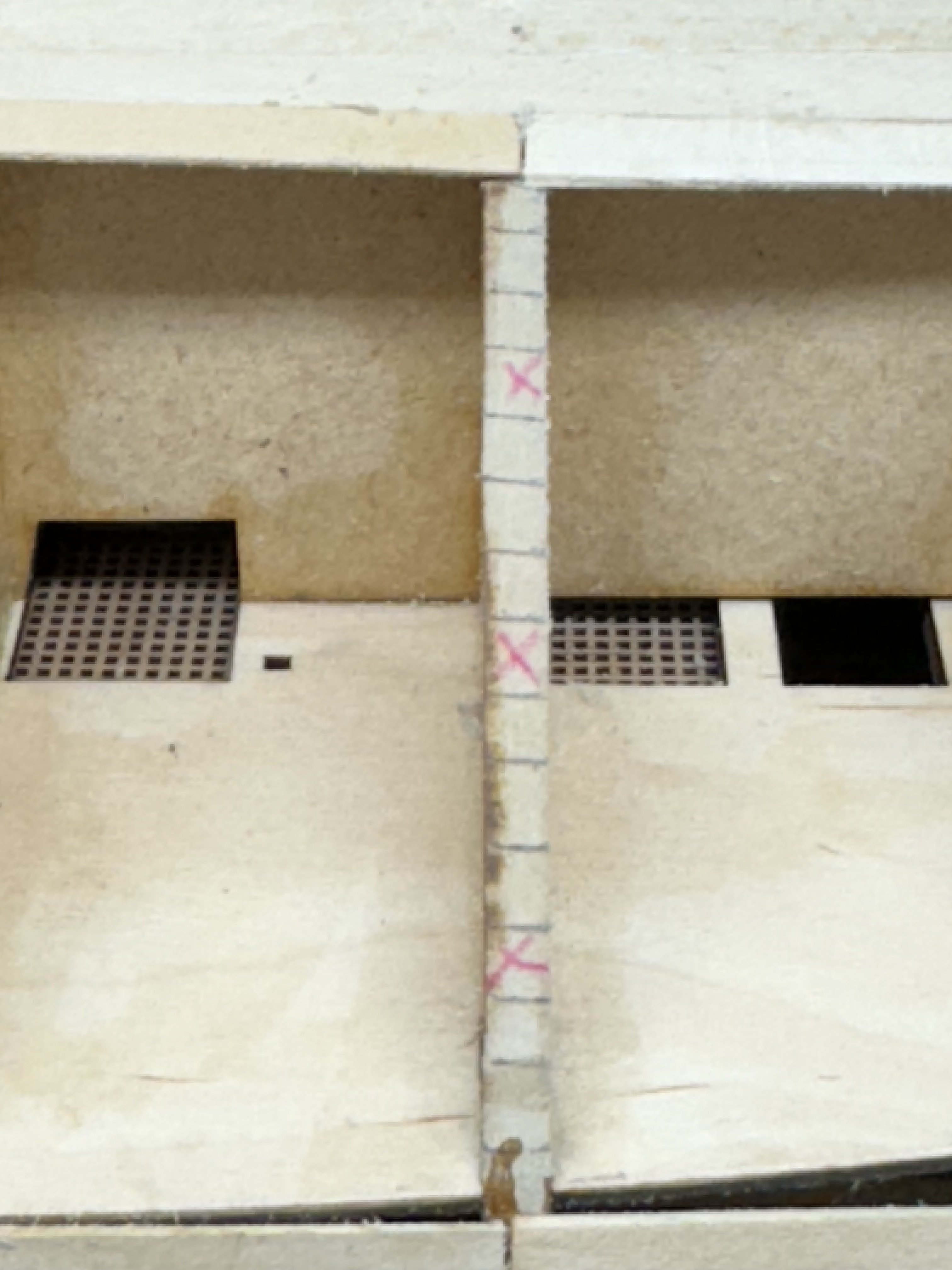
With three planks at the "top" and two at the bottom on each side I got out my "planking fan" and tick strips and laid out the starboard side. I measured 93mm at the widest point, measured a random selection of the provided planking and came up with an average width of 5.2mm which yields 18 planks to cover the rest of the hull. I decided on a four step plank length scheme and marked the bulkheads so I would actually have a chance of following the plan. "X" marks the spot like on a treasure map. I plan to alternate one plank on the bottom and then one on the top on each side. Here is the starboard side after two additional planks on the bottom and one on the top. On to the port side with tick strips and planking fan in hand.

- 422 replies
-
- 5
-
-
- Vanguard Models
- Sphinx
- (and 1 more)
-
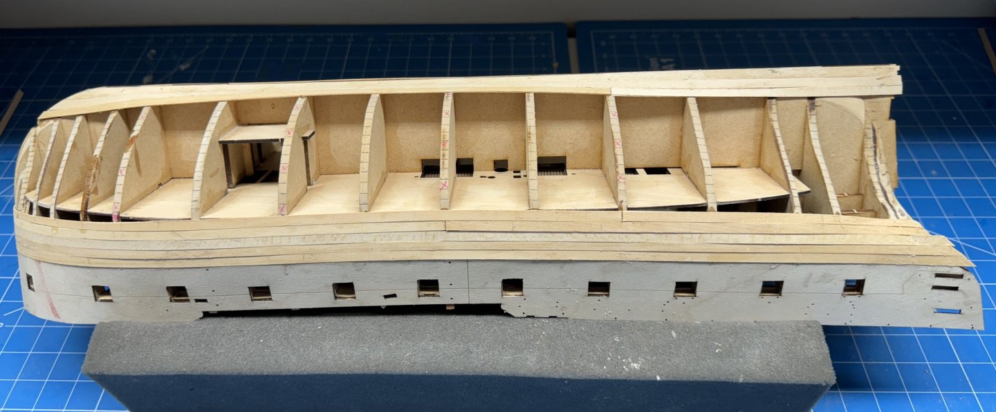
With three rows of planking at the "top" I decided to add the garboard strake and maybe one more at the "bottom" before proceeding with the rest of the hull. I added the garboard strake full width throughout I used pins on the midships and forward end (except at the very front where I used medium CA and a clamp to secure that end) and beveled the edge that meets the "keel" to get a tight fit which (hopefully) is the objective - to form a "V" shaped notch when the "real" keel is added. I then painted on the PVA/H2O mixture and let it set for several hours before proceeding. I am going to add another full width plank above the garboard strake before "getting on with the job at hand".
- 422 replies
-
- 7
-
-
- Vanguard Models
- Sphinx
- (and 1 more)
-
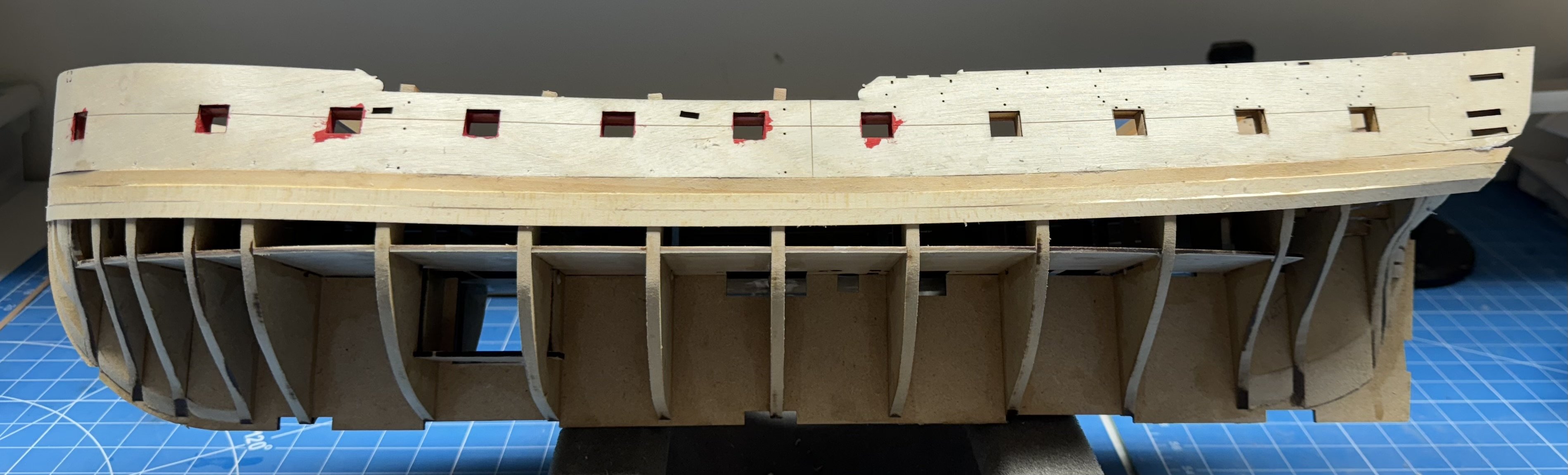
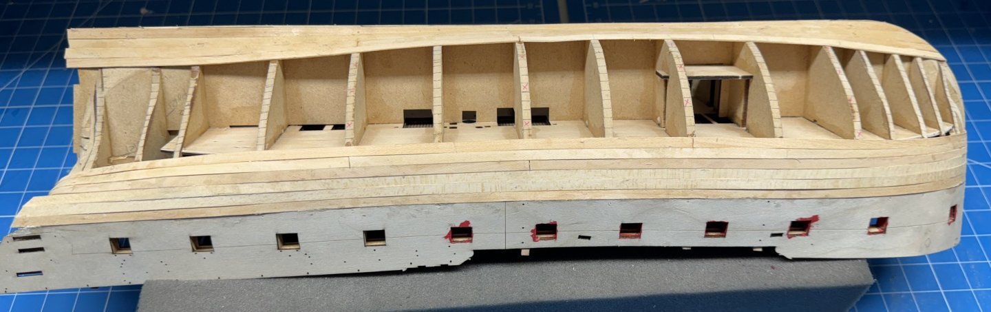
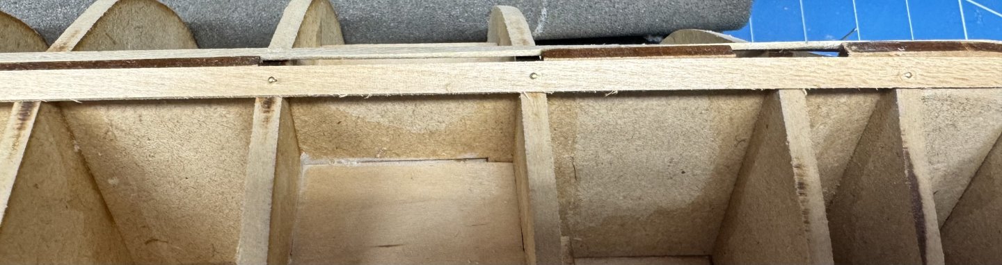
First three rows (the easy ones) done on each side. Planks matched up quite well with the upper bulwark except for one area at the bow on the port side - you can see the shadow where the bulwark is sticking out past the first row of planks. I have to find where I put my edgewise plank bender and steal the iron once I get a few more planks done. In the meantime I am changing all the blades in the Xacto knives and looking for my plank cutting jig.
- 422 replies
-
- 5
-
-
- Vanguard Models
- Sphinx
- (and 1 more)
-
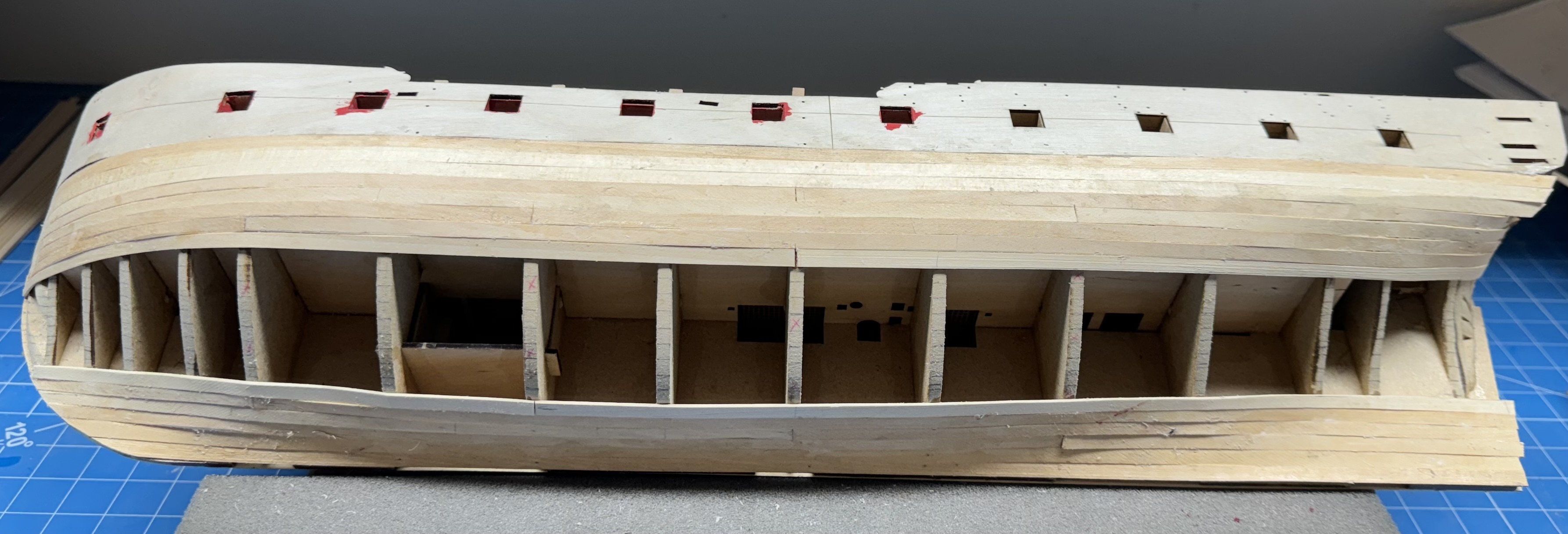
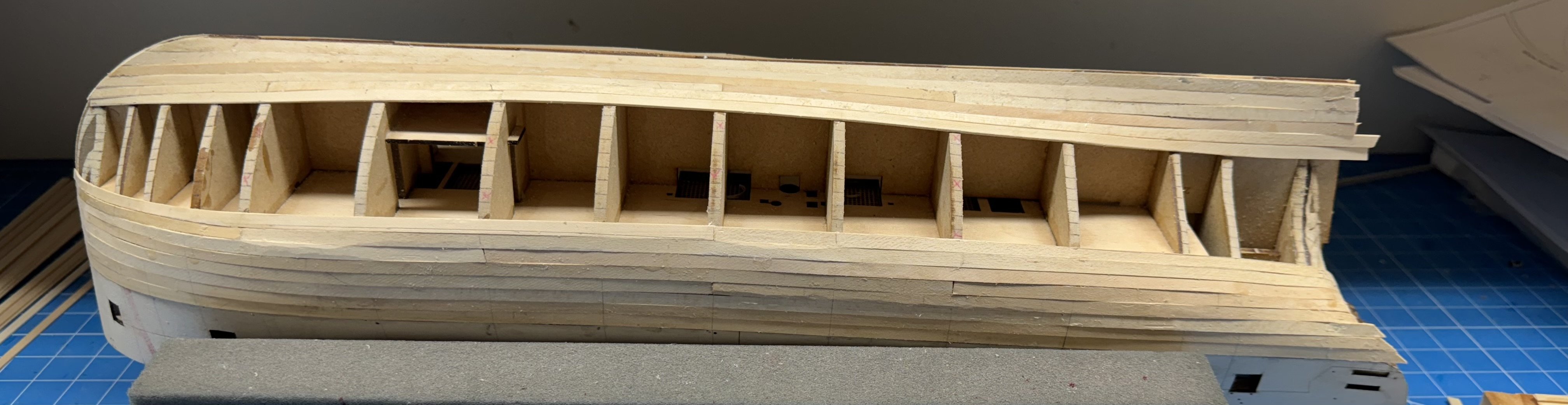
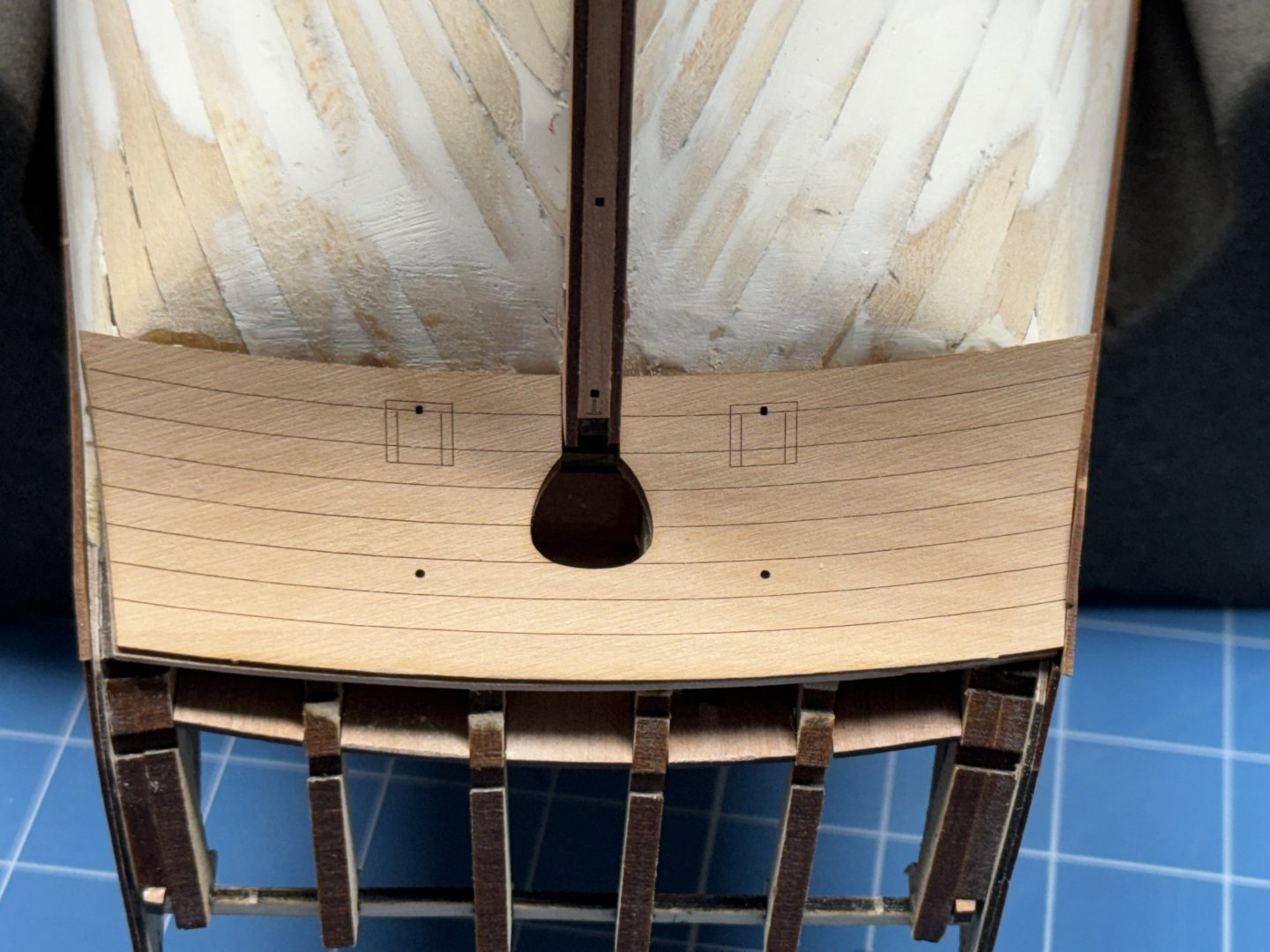
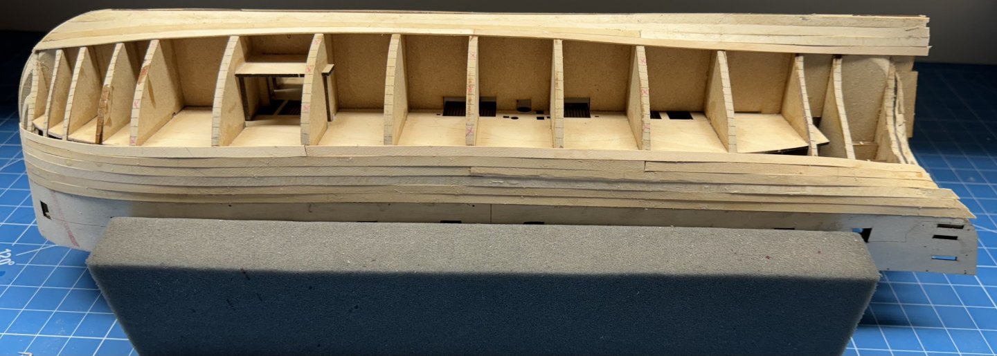
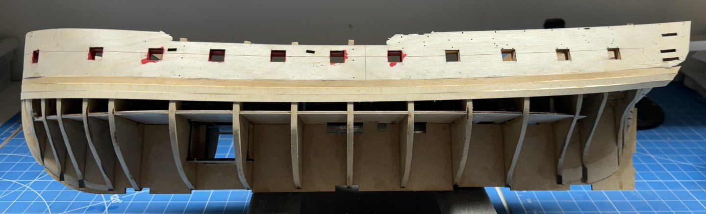
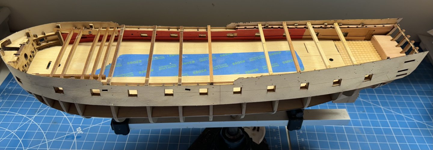
Ready to start the first layer of planking. I created my own set of jigs for the q-deck area since I managed to break off all the bulkhead extensions that would have supported the kit provided jig(s). hopefully they will do the job.
- 422 replies
-
- 4
-
-
- Vanguard Models
- Sphinx
- (and 1 more)
-
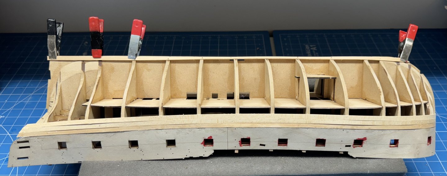
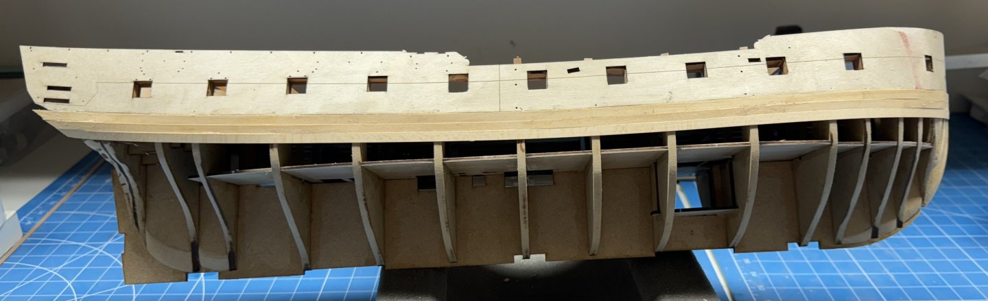
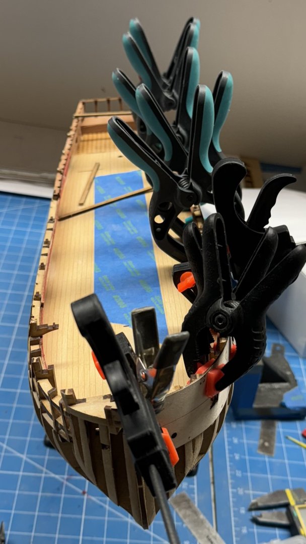
Port side exterior bulwark in place and the glue drying. I put a pin at every bulkhead to make sure there is consistent contact and (hopefully) no "waviness" at the bottom of the bulwark - another lesson from the previous "go-round".

- 422 replies
-
- 7
-
-
- Vanguard Models
- Sphinx
- (and 1 more)