HOLIDAY DONATION DRIVE - SUPPORT MSW - DO YOUR PART TO KEEP THIS GREAT FORUM GOING! (Only 75 donations so far out of 49,000 members - C'mon guys!)
×


cdrusn89
-
Posts
1,915 -
Joined
-
Last visited
Content Type
Profiles
Forums
Gallery
Events
Everything posted by cdrusn89
-
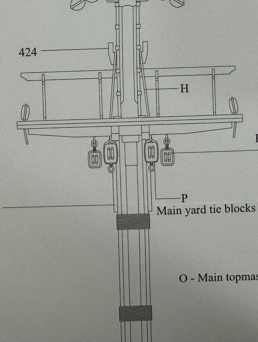
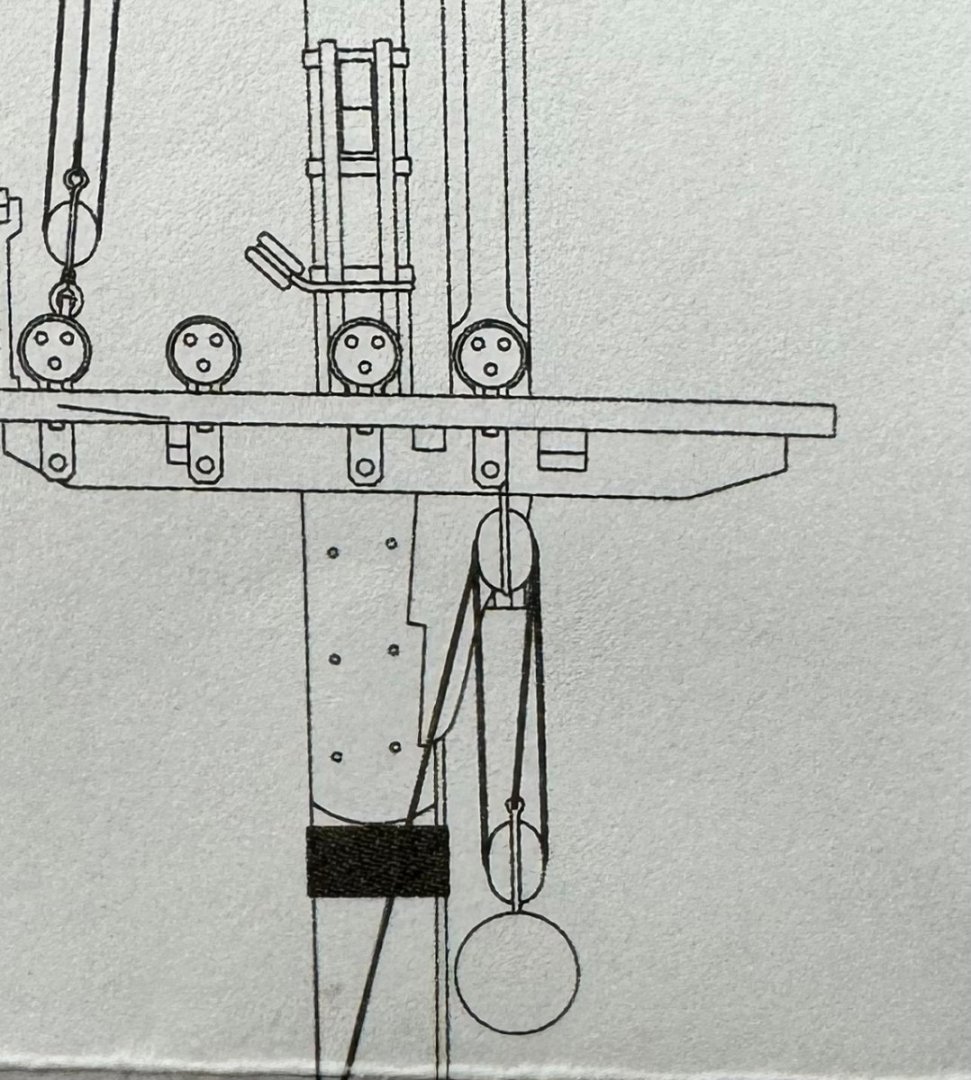
 While procrastinating getting on with the second layer of planks I went back to the Main Mast and looked at the rigging. I found an inconsistency between the rigging plans (Sheet 3) and the mast/yard drawing for the Main and Fore. I assume someone else has already caught this as there are many who have preceded me in this journey. The mast and yard drawings imply that the standing end of the tackle that raise the main and fore yards (I think they are called yard ties on the plans) is on the mast. Somewhere in one of the other build logs it is stated that the ring at the bottom of the block indicated the standing end of the line goes "here:. However the Rigging Plan sheet 4 pretty clearly (to me) shows the standing end to be on the yard. The yard drawings (this applies to Main and Fore only) is consistent with the mast drawing - no "ring" at the top of the respective blocks. This configuration is correct for the Mizzen as there is a single block on the yard where the Main and Fore have doubles "above and below". And now (after I fix the blocks on the Main mast) back to the planking.
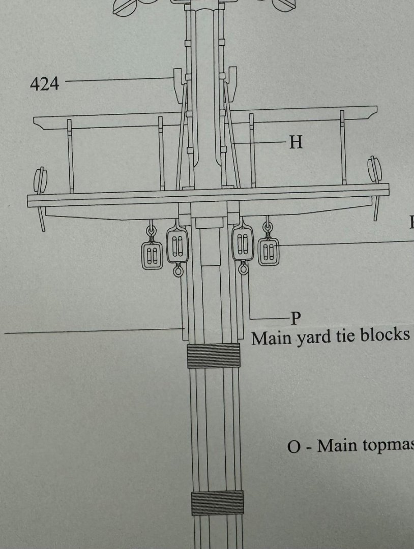
- 422 replies
-
- 2
-

-
- Vanguard Models
- Sphinx
- (and 1 more)
-
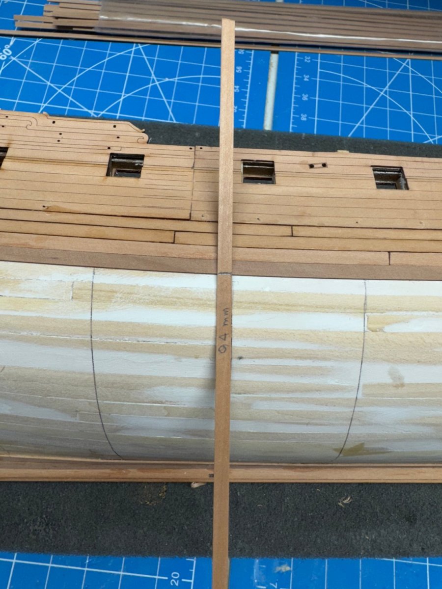
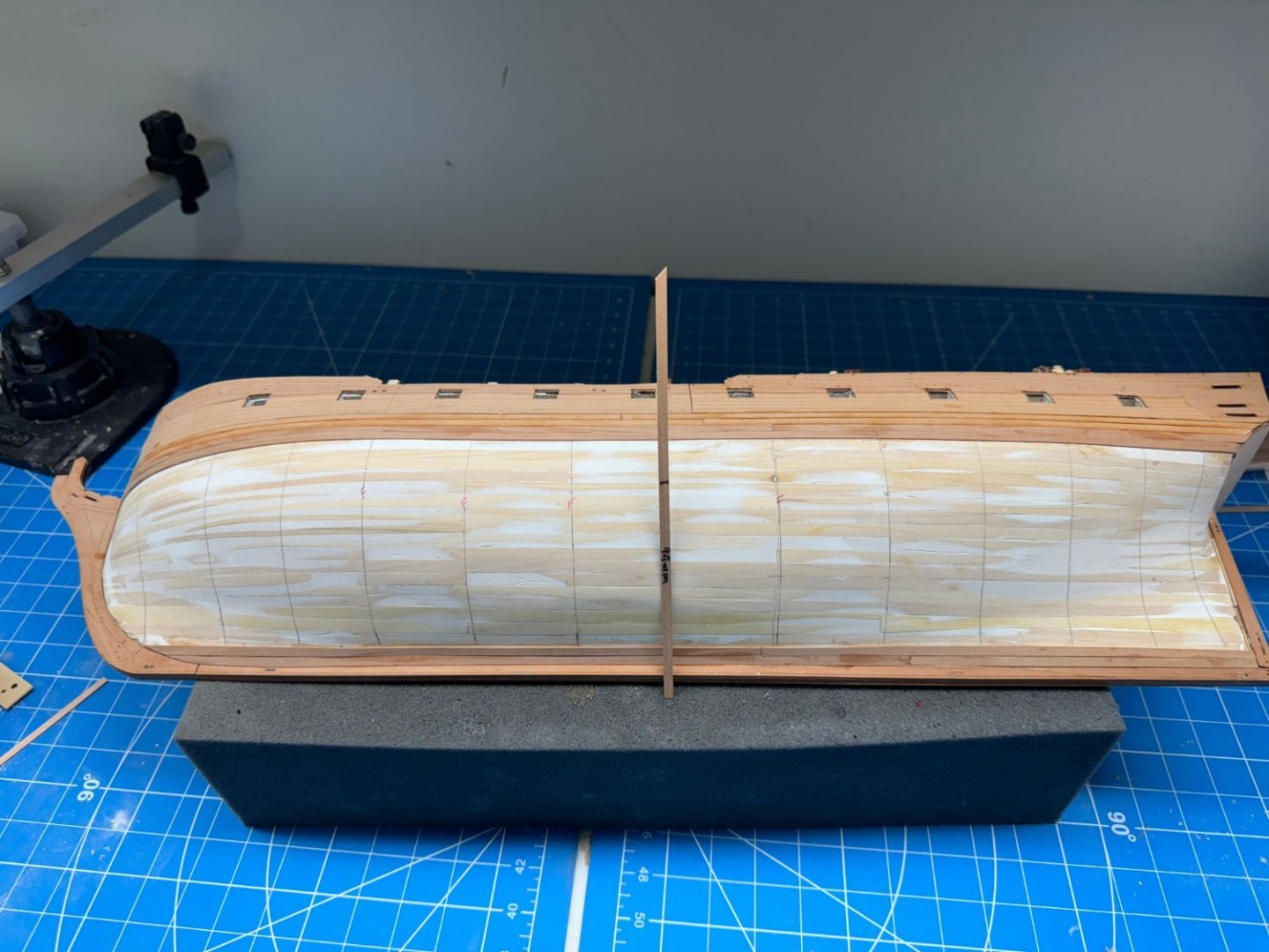
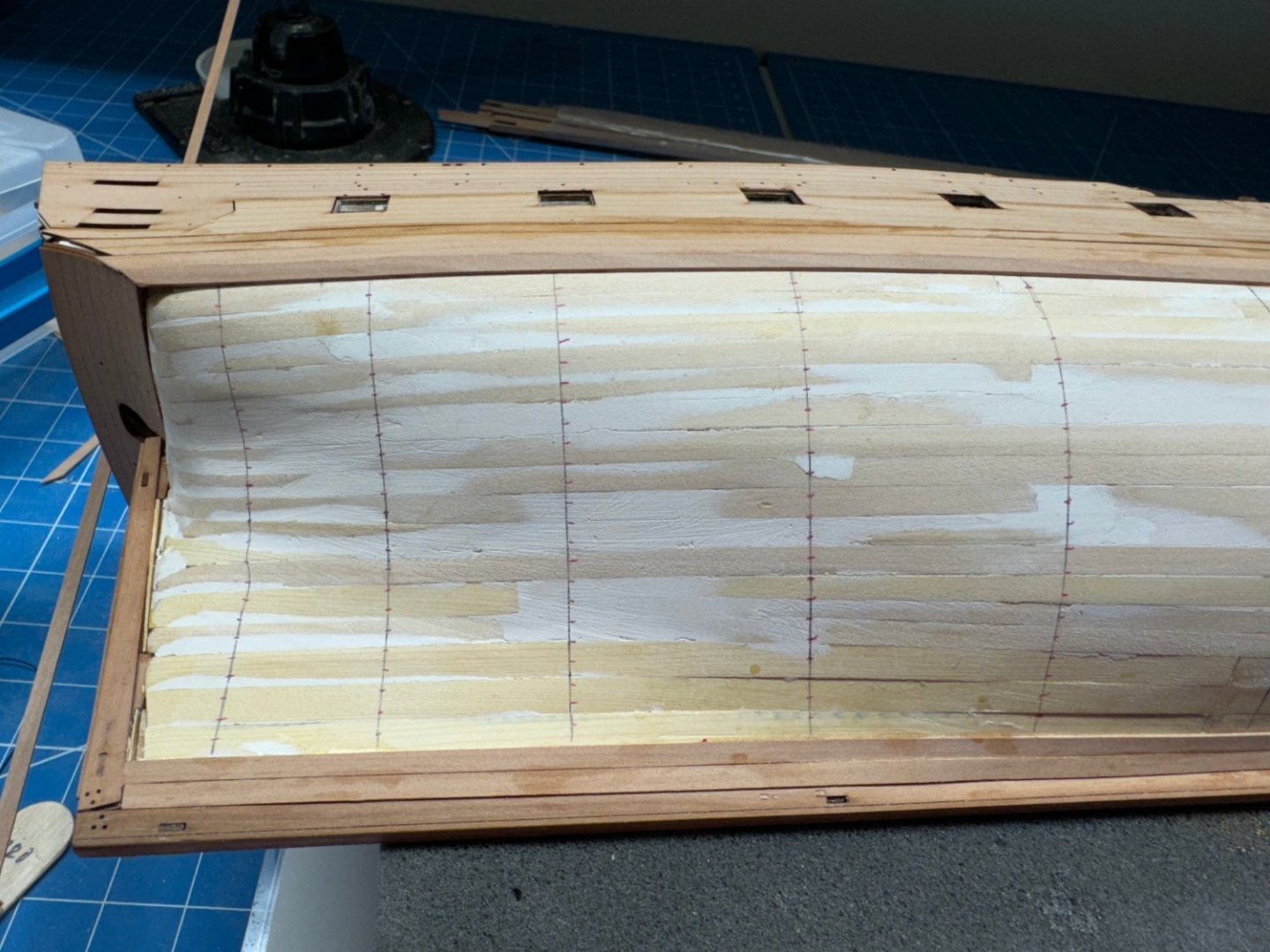
I added the four additional planks to the port side and measured at the amidships bulkhead and wonder of wonders it is the same 94mm as on the starboard side. I checked fore and aft of amidships and the same four additional bulkheads will need full width planks. Excellent kits design and manufacturing to get things to work out "as they should". Maybe a little skill in assembly as well. Now to "tic strip" the port side and start planking "in earnest".
- 422 replies
-
- 7
-
-
- Vanguard Models
- Sphinx
- (and 1 more)
-
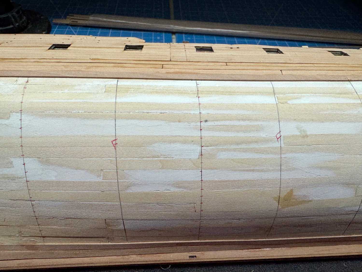
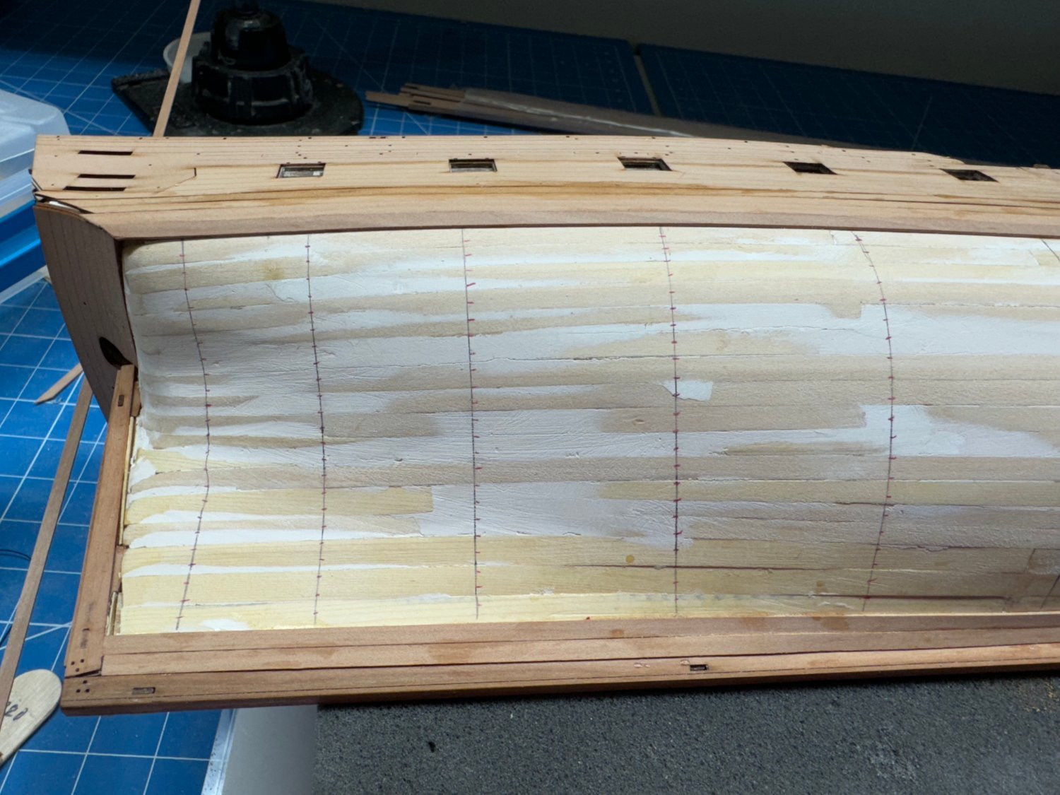
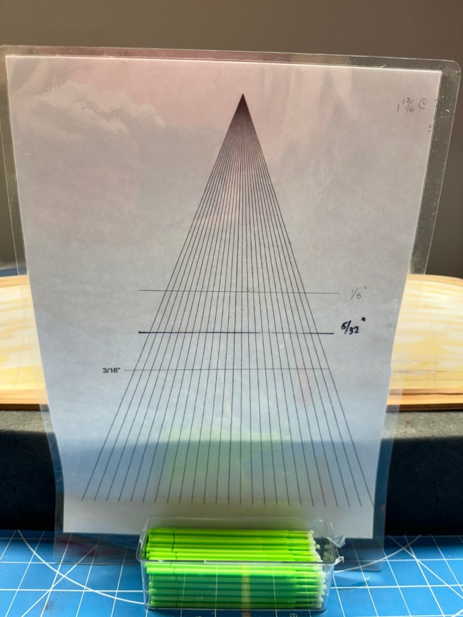
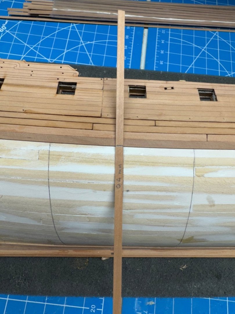
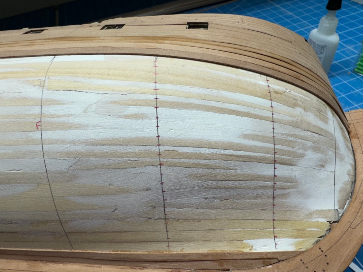
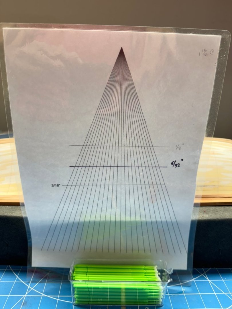
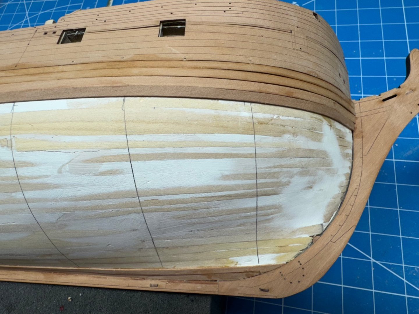
On to the planking. After getting the top two rows supplied with the kit in place I measured the distance from the keel to the bottom of the upper planks (in mm - makes the math easier) and divided by the 4mm plank width and found I needed like 28 planks to cover that span. That presents a problem for me as my planking fan is only 24 ticks wide. The 5/32" line is approximately 4mm so if all goes well all the strips should fall at or above this line. To solve the planking fan issue I added four more rows of un-tapered planks, two at the keel (garboard strake plus one more), and two at the top. I measured again and got 94mm which if my calculator is correct means 23.5 (aka 24) planks to fill this area. I got my tick strips out and measured, marked the strip then marked the hull at the bulkhead (more or less) locations I had drawn on the hull. I used a red colored pencil to mark the hull so I am not confused by errant pencils marks which may be on the hull. I have not decided how to handle the very forward area yet - I have the book, perhaps I should re-read that section. I am going to have to build a jig from cutting the planks to the required dimensions. Doing it by the unaided hand has never been one of my strengths. I marked the midships (aka widest point) bulkhead and then used that tick strip to see how far fore and aft full width strips would "work". I marked those bulkheads with "F" - I did not see any sense in marking the ticks since what they mainly provide is the plank width at that bulkhead.


- 422 replies
-
- 7
-
-
- Vanguard Models
- Sphinx
- (and 1 more)
-
I have a serving "machine" both the powered (which I have never used) and manual (from Syren). I served the shroud loop and the fore and main mast stays (there were only two masts - Niagara). I remember it was a lot of work and when done unless you knew it had been done it was really hard to tell. Those fishing lures I used to get some weight on the planking a few posts back were used to get the served lines to hang straight as they had a tendency to want to twist and turn. It worked out okay in the end but it was a lot of effort for little payback except knowing you did it. I am going to set up the powered one (from Russia before the war) and see if it materially reduces the effort. Then decide whether to serve the stays and shroud loops.
- 422 replies
-
- 1
-
-
- Vanguard Models
- Sphinx
- (and 1 more)
-
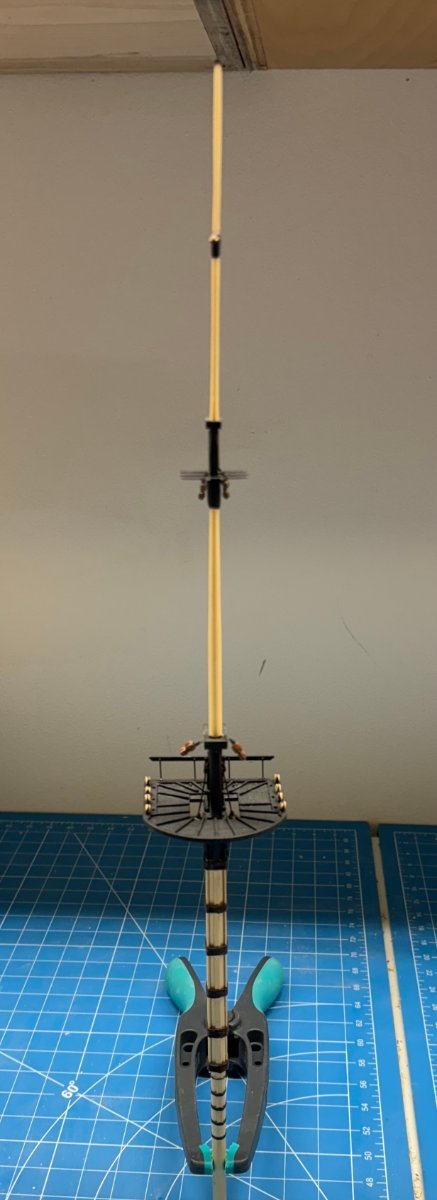
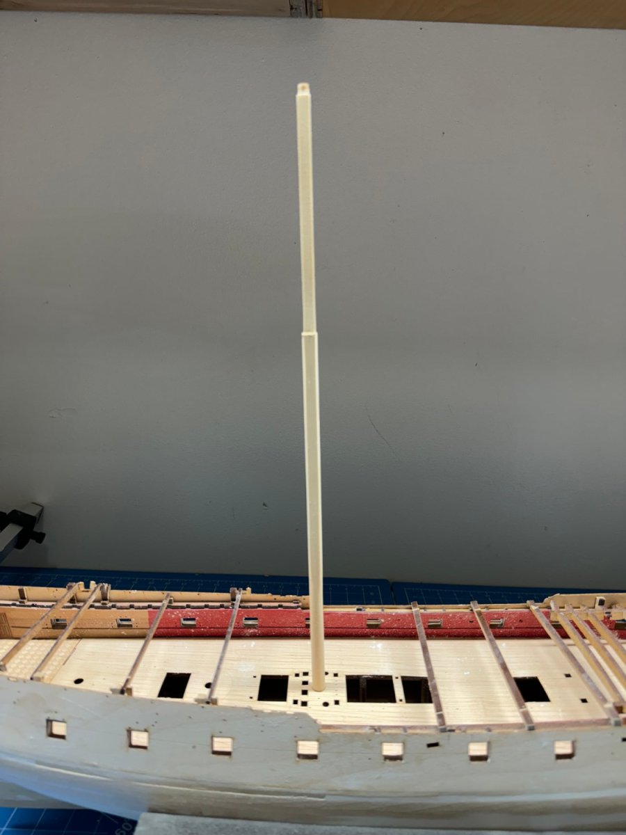
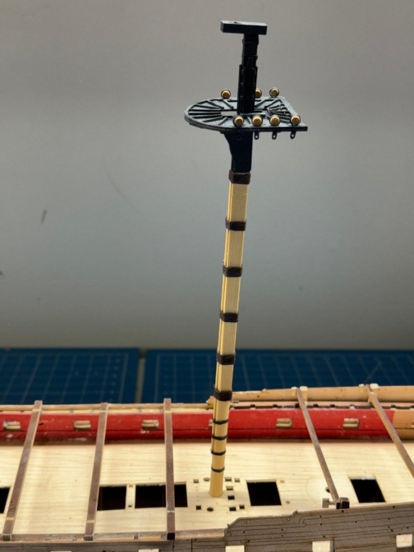
Thanks guys but, before I start on the hull planking I finished the Main mast as far as the instructions on page 121. I am thinking that maybe adding the upper stays/ratlines before installing on the hull might be at least worth thinking about. It would make getting the lower shrouds, etc. in place somewhat more difficult but it would certainly be easier (for me) to do that somewhat delicate (thinner lines/etc.) work where it is easier to get at and potentially lower on the work surface. I have found that the rigging done above the elbows particularly taxing. Anyway, here is the Main mast dry fit. I chickened out on the cap on top of the top gallant mast. I thought (briefly) about trying to fabricate it from the Alaskan Yellow Cedar but quickly returned to my senses and used the kit provided piece painted black. I have serious doubts about the AYC grain structure supporting really small pieces like required here. I also took the cowards way out on the fiddle blocks at the main cap. There is some discussion on some other build logs about where the securing lines should go - around the mast, around the cap, etc. I chose to put an eyebolt on each side and secure the fiddle blocks to them. I think I like the lighter color masts - more contrast with the black painted parts.

- 422 replies
-
- 7
-
-
- Vanguard Models
- Sphinx
- (and 1 more)
-
A planking we shall go; a planking we shall go..... Going to go cut some tic strips and find my planking fan. I am at least going to start in the "approved" manner this time.

- 422 replies
-
- 7
-
-
- Vanguard Models
- Sphinx
- (and 1 more)
-
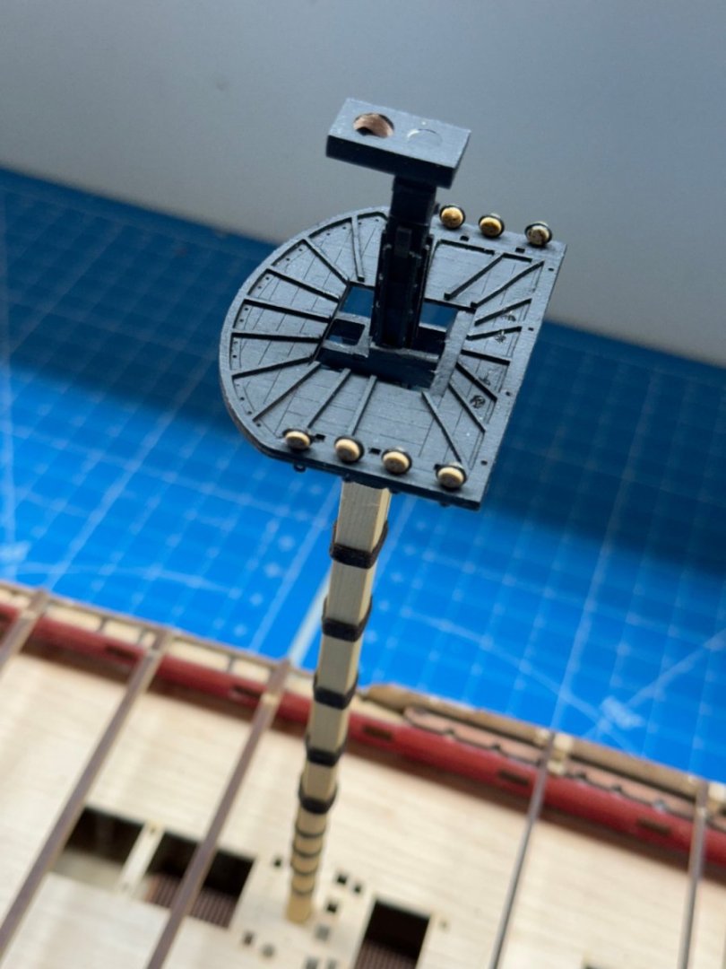
While waiting for various items on the hull to soak, dry, be fitted, glued and dry I have been building the masts. As I mentioned previously there are all from Alaskan Yellow Cedar (since that is all i have in big enough section to make 8mm square billets without getting out the 10" table saw). So here is the lower Main Mast with "all the fixens", except the blocks and railing. One word on the deadeyes and strops. I painted the strops before hand using an "etching primer paint" supposedly designed to use on photo-etched metal. I either failed to properly prepare the surface or the etching does really work because most of the paint flaked off during the handling necessary to get the deadeye into the strop. This meant a good deal of very fine paint touch-up. I have modified my prep techniques and hope for better results on the other masts, not to mention the fifty odd deadeyes in the channels.
- 422 replies
-
- 4
-
-
- Vanguard Models
- Sphinx
- (and 1 more)
-
Fishing line weights appear to have corrected the bottom edge of the lower planking and the transom finish "pattern" is now attached and waiting for the glue to set - then on to the kit provided planking and then....more planking "fun".
- 422 replies
-
- 6
-
-
- Vanguard Models
- Sphinx
- (and 1 more)
-
Despite the nails/pins I still found areas where the lower pattern was not glued to the first planking layer. I thought it prudent to correct this and since the nails did not seem to work I tried something else. I had the fishing sinkers from an attempt (ultimately successful) to get some line to hang straight. Hopefully I can move on to installing the transom and then the first two rows of planking provided in the kit.
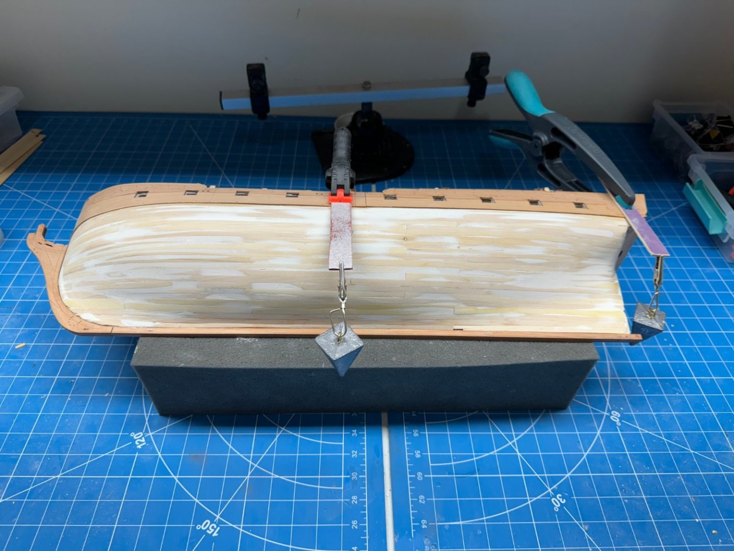
- 422 replies
-
- 5
-
-
- Vanguard Models
- Sphinx
- (and 1 more)
-
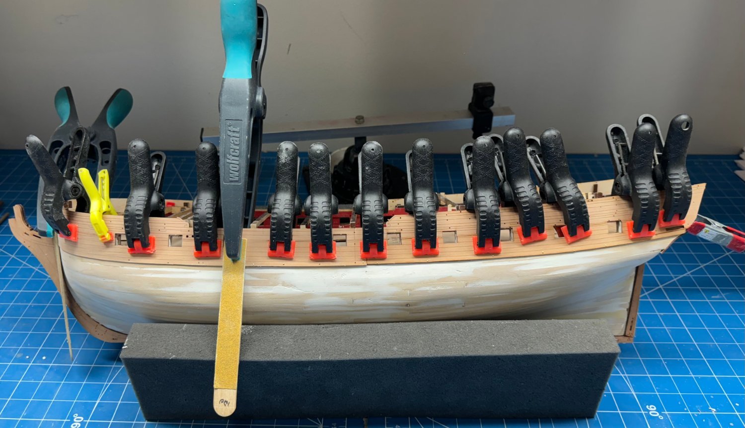
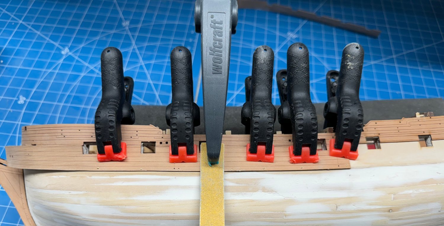
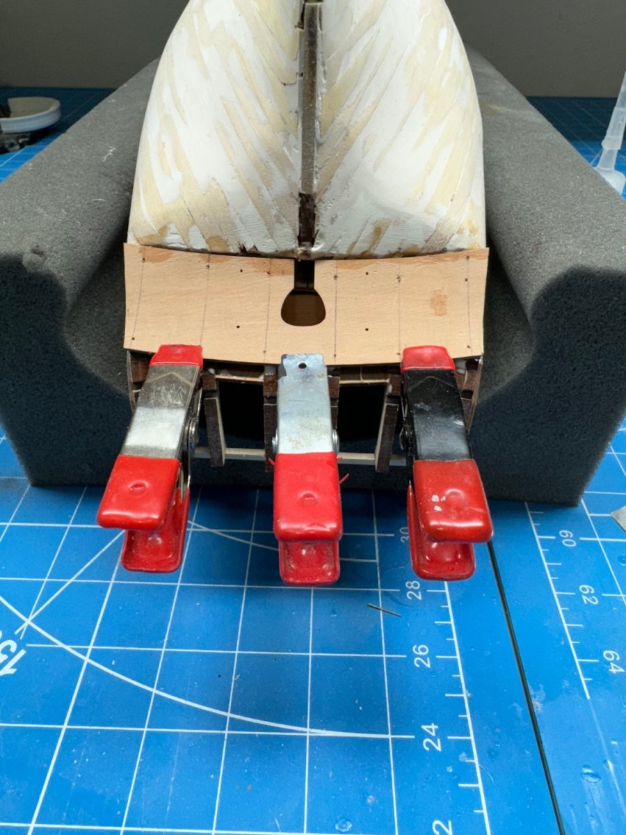
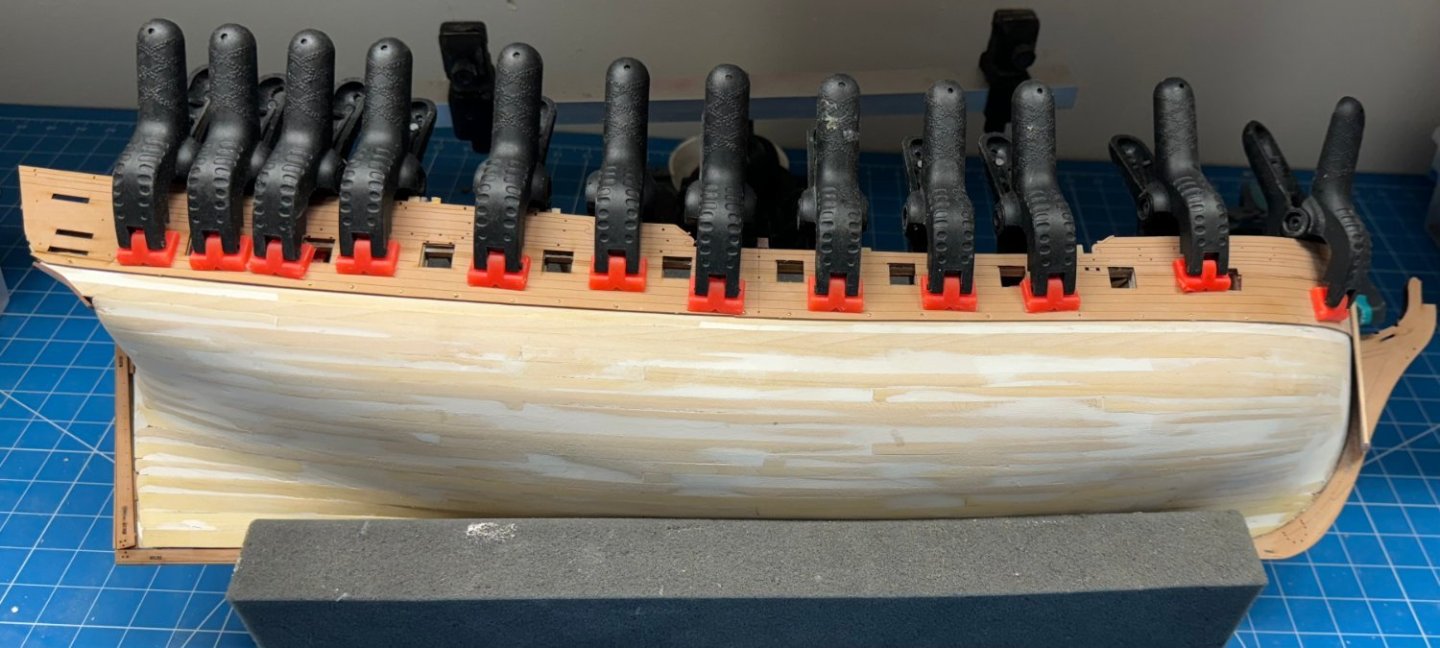
Starboard side "middle" planking patterns in place, glued and clamped. I put nails (aka pins) in along the bottom and tapped them down with a small hammer to try and ensure that the bottom edge in firmly glued to the first layer of planking (and filler). I will remove them once i am sure the glue has dried. According to the instructions this bottom "row" of planking will eventually be covered with the wales so the unsightly holes (and whatever damage removing the nails causes) will not be seen.
- 422 replies
-
- 7
-
-
- Vanguard Models
- Sphinx
- (and 1 more)
-
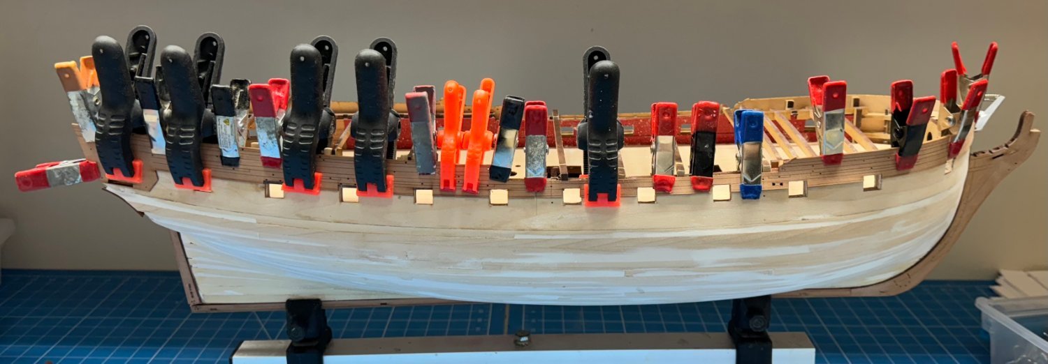
Forward portion of forward part glued and clamped along with the aft portion of the "middle" planking pattern for port side.

- 422 replies
-
- 8
-
-
- Vanguard Models
- Sphinx
- (and 1 more)
-
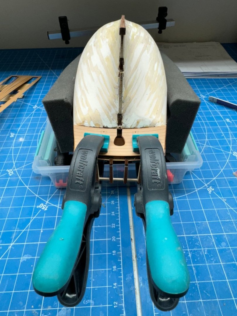
Continuing on with the hull and the "middle" set of external planking "patterns". I had to "fiddle" with the forward edge of the port side pattern to get the gun ports to all line up (more or less). It seemed difficult ot get them all to line up at the same time - move one end a bit and it is off somewhere else. I decided it was more important to get the midships ports aligned as these will be the most visible so I chose to get these glued down first and then deal with the bow when this piece is set. I will work the starboard side when the port is done - the pattern is already bent and dry - I will take the instructions word that it will retain its shape for another day. FYI the sanding stick is in there to try a get more pressure at that point. The nail did not hold very well and I can't get a clamp that low.

- 422 replies
-
- 7
-
-
- Vanguard Models
- Sphinx
- (and 1 more)
-
I have decided to redo the masts and leave them the natural AYC rather than try and stain them to match the pearwood. The stain looked okay on the lower masts but it was all blotchy on the topsail masts for some reason - probably poor staining technique on my part. That notwithstanding I think it will look better with the light masts and black yards. And i am getting pretty good at fabbing more or less circular masts from square stock. Below are the new cheeks and front fish fabbed in AYC along with the Main Top Gallant Mast. I did learn (or maybe relearn) a valuable lesson when thinning the spar down to the required dimension. Start at the thin end and work toward the thicker end. Don't ask me how figured that out. I'll just say I know exactly where the weak point of the Fore Top Gallant Mast is located. I have to try and disassemble the Mizzen Mast so I can reuse the parts as I have no desire to try and replicate the mast top and mast caps from scratch. Not to mention the PE upper top.
- 422 replies
-
- 5
-
-
- Vanguard Models
- Sphinx
- (and 1 more)
-
Done - thanks - since you remove the tabs the stiffeners attach to perhaps I won't need the alcohol; just carefully cut the tab off with the stiffener still attached.
- 422 replies
-
- 1
-
-
- Vanguard Models
- Sphinx
- (and 1 more)
-
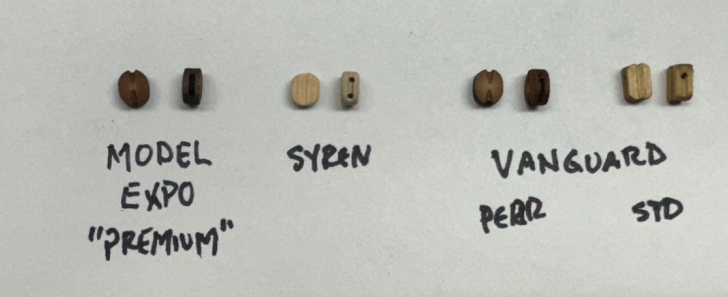
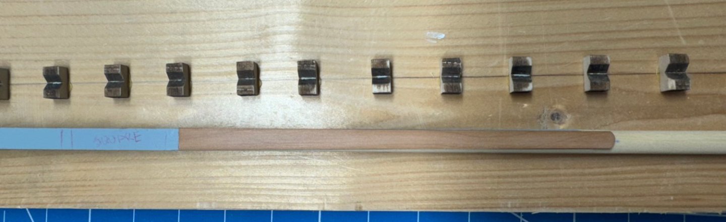
As promised here is a rigging block comparison. All are 5mm singles.
- 422 replies
-
- 3
-
-

-
- Vanguard Models
- Sphinx
- (and 1 more)
-
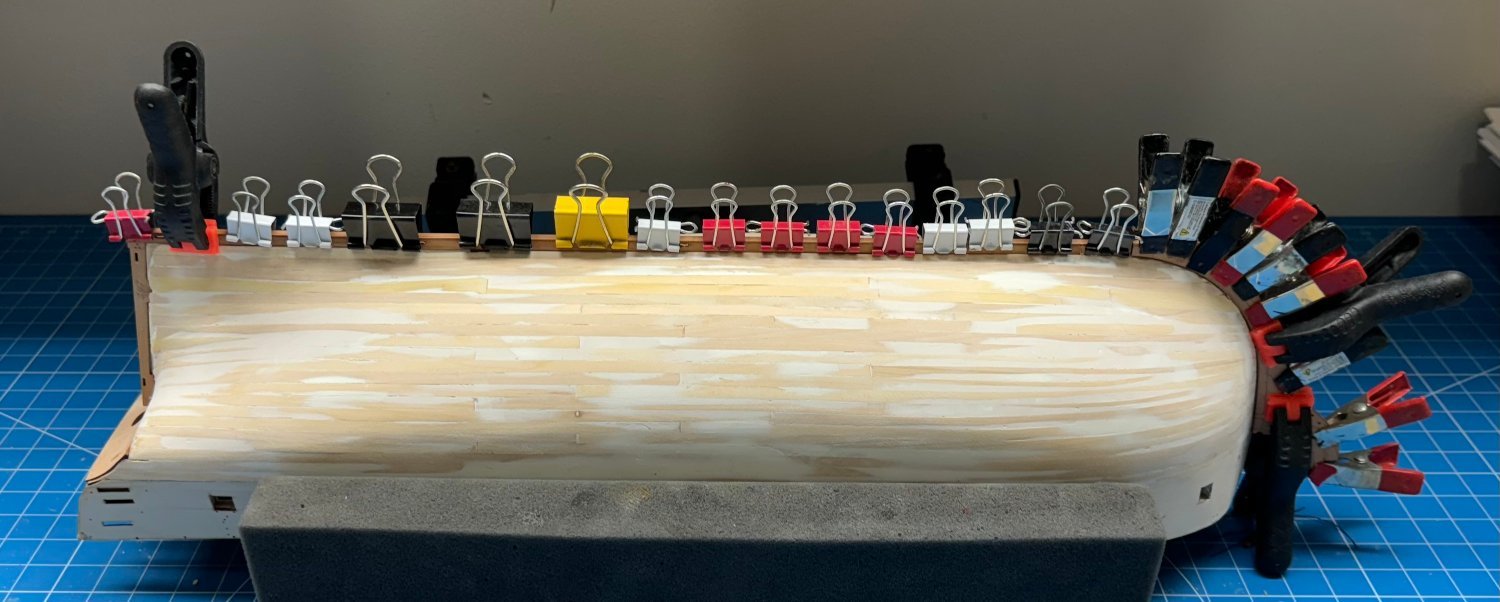
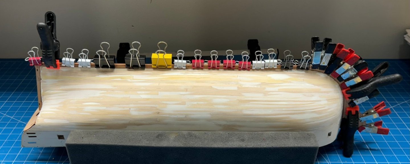
Here is the upper/upper planking on the starboard side waiting for the glue to set. I used 60/40 PVA/Water brushed on the hull as recommended in the instructions. I decided to do both pieces on each side because I needed to add a clamp through the bullnose to hold the bottom of the the most forward edge of the forward pattern. I suspect I will need to do something similar on the port side so...

- 422 replies
-
- 5
-
-
- Vanguard Models
- Sphinx
- (and 1 more)
-
Keel, stem and stern post added and hull is back on the Amati holder ready for the upper planking to be added. As yhou can see, keeping the hull stiffeners in place is not that easy. They are not that snug a fit on the little tabs anymore after being taken on and off repeatedly not to mention jostled around during the planking.
- 422 replies
-
- 3
-
-
- Vanguard Models
- Sphinx
- (and 1 more)
-
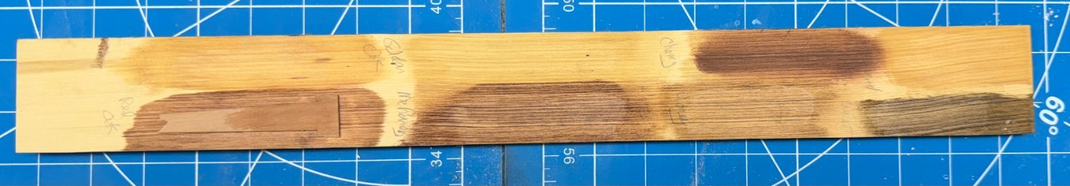
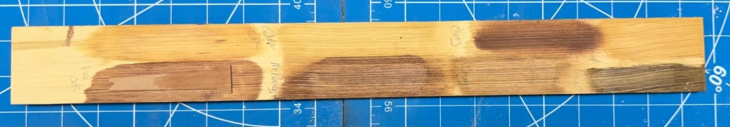
If I am to use masts fabricated of Alaskan Yellow Cedar (at least the lower and topsail masts - the jury is still out on the Top Gallant masts) then I need to figure out what color they need to be. I am not sure I would like the "bright yellow (which is what AYC looks like after a coat or two of WoP) since much of the mast is covered with the cheeks and front fish which are provided in pearwood. I suppose I could fabricate them out of AYC but they have a pretty particular shape and while not impossible I do n ot want to tackle that as well as fabricating the masts. So I assembled all the cans of stain in the "paint locker", a piece of AYC (from the same billet I cut the mast pieces from) and a section of the kit's carrier sheet that held the cheeks. I put a sample of the stain on the AYC then, when dry a coat of WoP and well as a coat of WoP on the kit carrier sheet. Here are the results. As can be seen the Minwax Red Oak stain comes the closet to matching the kit's pearwood so I will stain the mast sections with that before assembling the lower masts. And the WoP makes a real difference darkening the pearwood.
- 422 replies
-
- 4
-
-
- Vanguard Models
- Sphinx
- (and 1 more)
-
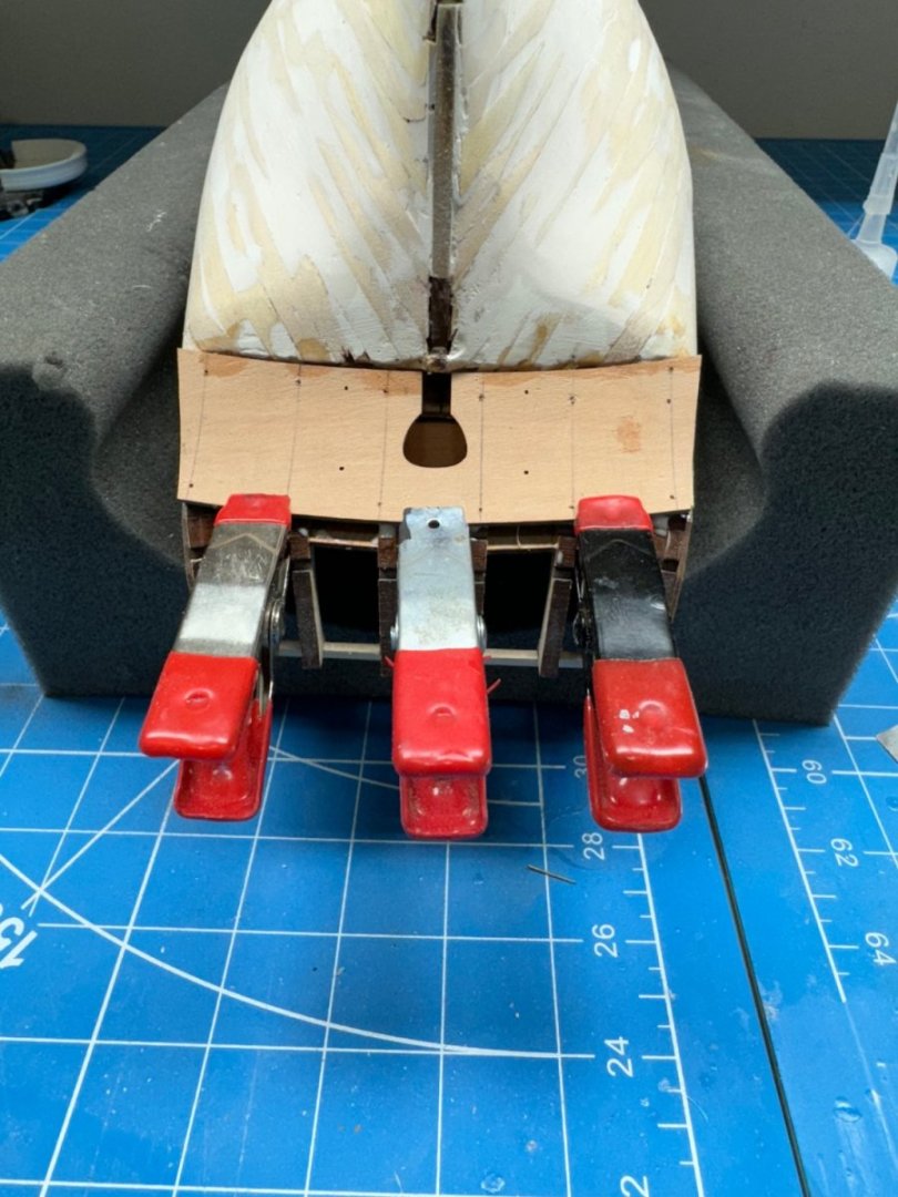
One side of the stem and keel outer "patterns" in place and clamped while the glue (60/40 PVA/Water) sets. Did I mention you can't have too many clamps? FYI - I have to sand down the location pegs a bit to get them into the slots. Took the laser char off the edges and rounded one side and they fit in without undue pressure. I used my parallel jaw pliers to push them in until one side was flush then pushed them through the rest of the way with regular pliers.
- 422 replies
-
- 7
-
-
- Vanguard Models
- Sphinx
- (and 1 more)
-
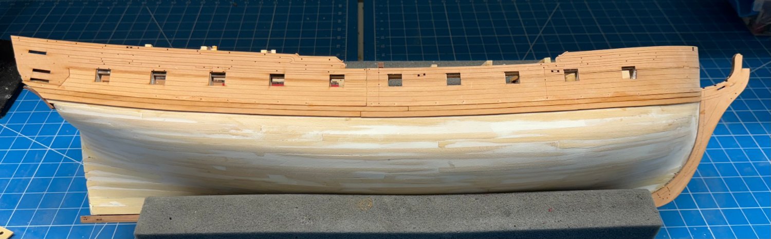
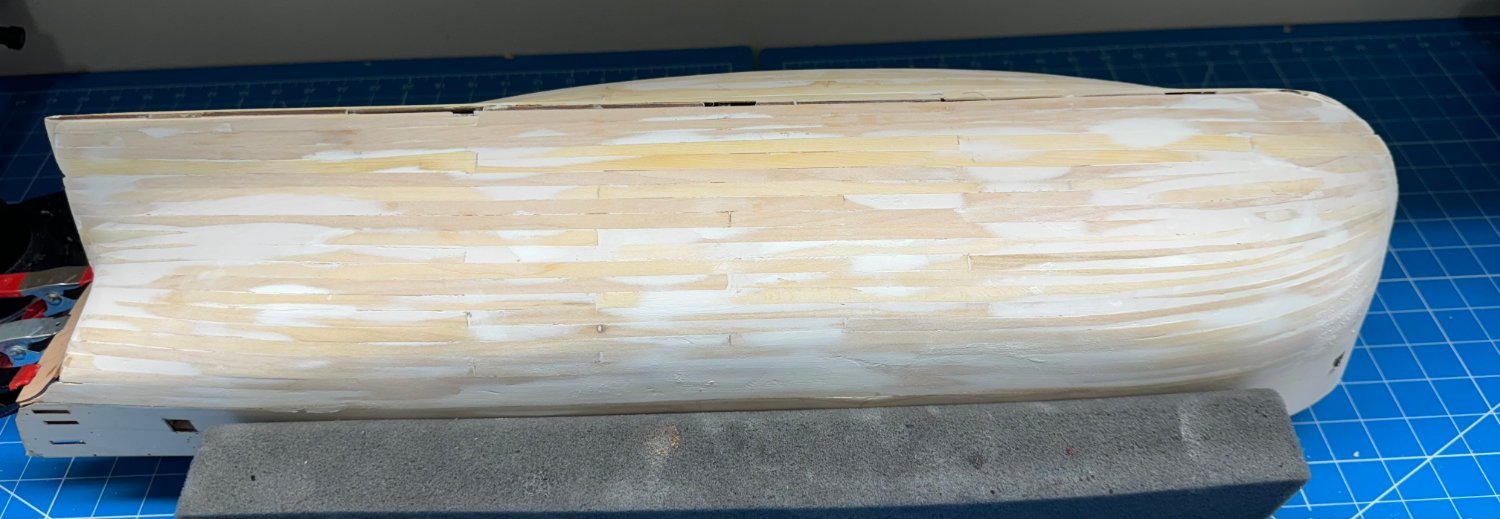
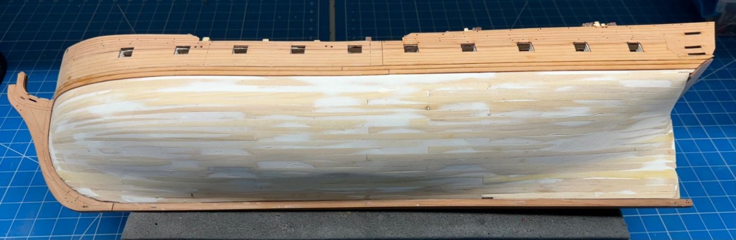
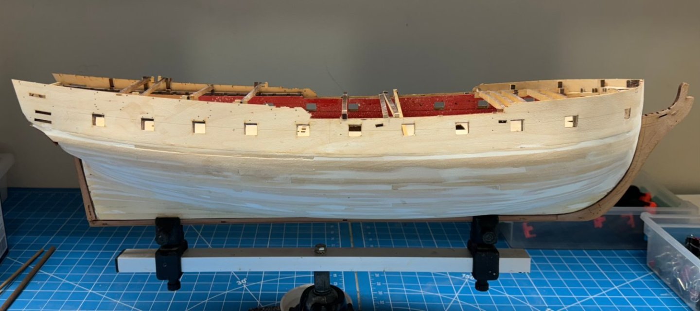
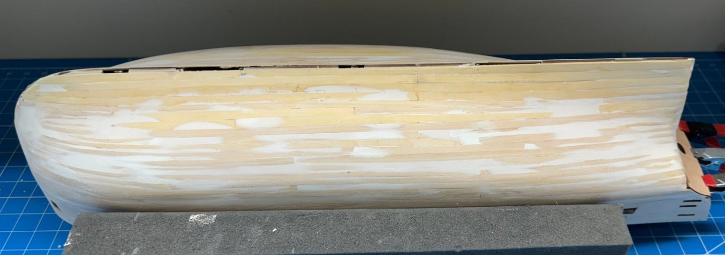
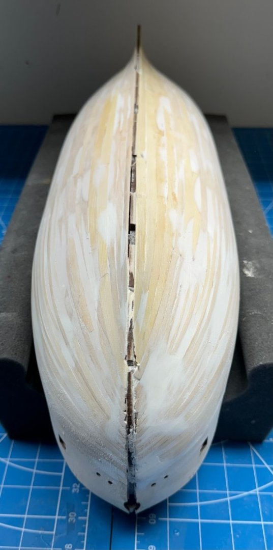
Back to the hull. I got the stern transom pattern in place. I did soak and used rubber bands to hold it against something curved. After cleaning up the planking edges I glued the bottom to the hull and held it in place with pins. When that was dry I added more PVA to the upper parts of the stern timbers and used clamps to bring the counter in contact with the timbers. I have decided that the first layer of planking is at the "good enough" stage and am going to proceed with preps for layer two. Here is what it looks like now - clearly not the best planking job as evidenced by the considerable amount of filler present. Hopefully I will be able to do a better job on the "finish layer "- at least where it will "shows".

- 422 replies
-
- 5
-
-
- Vanguard Models
- Sphinx
- (and 1 more)
-
When I get the Vanguard blocks (Monday hopefully) I will post pictures of the Vanguard "standard" and pearwood as well as the Model Expo "Premier" and the Syren blocks. You can judge for yourself but it will be awhile before you can see them "in use" except for those attached to yards and masts. FYI - according to the Vanguard website I got the last Sphinx pearwood block set (the site said they had one in stock when I ordered them).
- 422 replies
-
- 2
-
-
-
- Vanguard Models
- Sphinx
- (and 1 more)
-
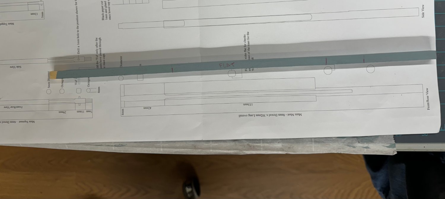
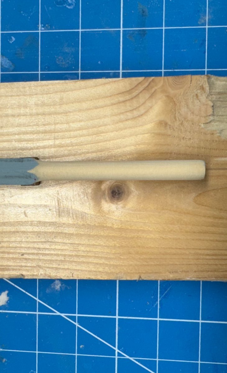
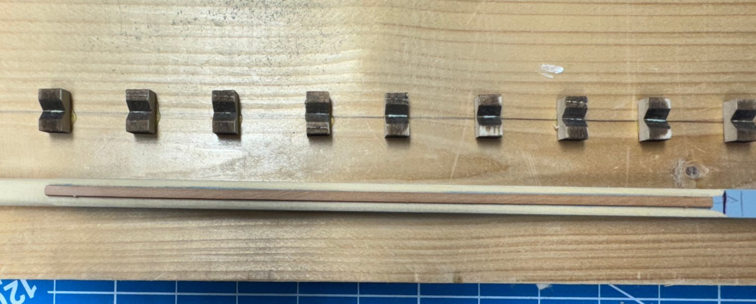
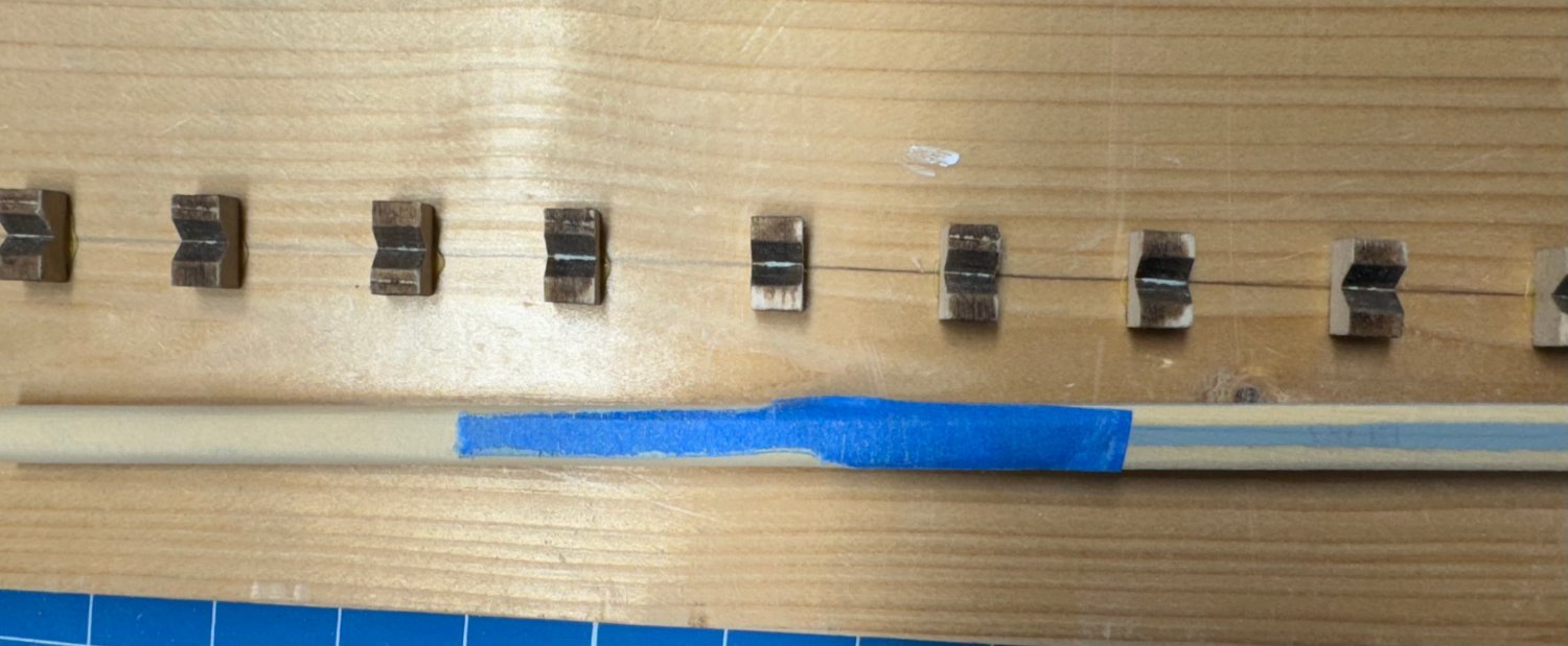
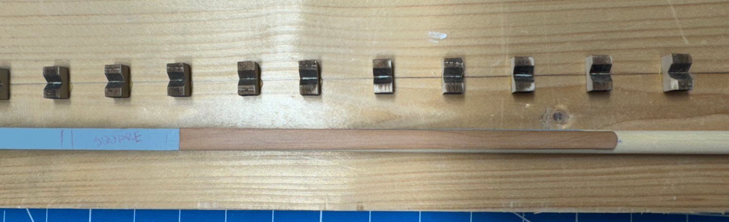
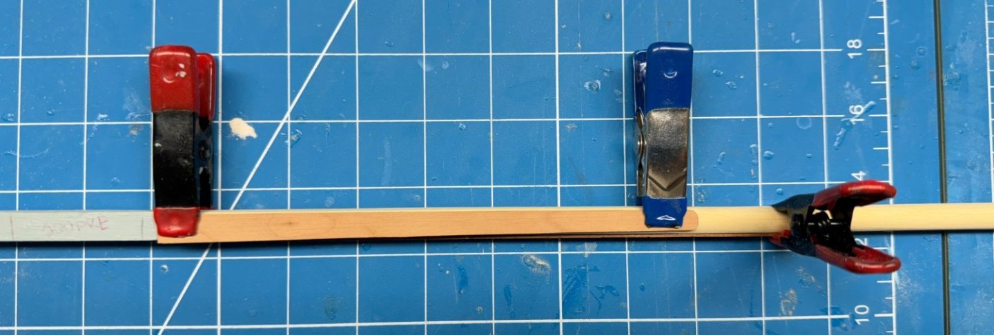
I finally broke down and ordered the Vanguard pear wood block set. It will be here Monday (so says UPS) So I am working the hull (fitfully) and now the Main mast. Looking at the drawing I noticed that much of it is flat sided for the "Front Fish" and the cheeks. While the instructions provide a methodology for making the long flat sides on a dowel I thought it might be easier (for me) to start with a square piece and then make it round where necessary. Unfortunately I did not have a basswood piece 8mm square (or larger) so I cut a piece of Alaskan Yellow Cedar to 8mm square and marked it according to the plans. 98504568-6DB4-44D6-84FF-7954EADBF3E7_1_201_a.heic Then I took the easy part - I made the bottom round the same way I did the yards - make eight sided then sand and sand. Yes it is a little bigger at the bottom but that will be corrected when I do the 220 finish sanding. I measured and it is 7.7mm in diameter at the bottom. Close enough to 8mm (I hope). Then on to the front and the flat for the front fish. I used the same technique just only "eighthed" the two corners on the front. It took some finesse but I got the flat mostly just wide enough for the fish. The paint really helps (me) see where has already been sanded. Now the section of the mast between the bottom of the fish and the bottom of the cheeks needs to be rounded. I put some masking tape over the "fish flat" and then rounded the other sides as usual. On to the sides and the first "issue". The plans seem to show that the pole is rounded somewhat the entire length of the cheeks. However, the cheeks are nearly 8mm wide at the top making me wonder how I would flatten an 8mm dowel to support the cheeks which are nearly 8mm wide. Here are the cheeks sitting on the unmodified side of the square mast. I am tempted to just round off the lower portions on each side of the mast but this will leave the back almost flat as well. I rounded off the edges on each side enough to make the back not completely flat and then sanded off all the gray paint below the square section so there is no chance of it bleeding out when the finish is applied. Here is the mast with the cheeks and fish clamped on - no glue yet. Now on to the square section and cap. And here is the completed Main mast less the fish face and cheeks. I am in a quandary about the color of the masts. The dowels provided are of several colors, mostly pretty dark. I already have the Mizzen "done" so I can't redo that without risking destroying some (maybe all) of the other pieces (trestle trees etc.) so I need to stain the Main (and presumably the Fore since it is very similar in shape/construction to the Main) lower section to match the dowel color I used on the Mizzen. May take some experimentation but I have more AYC in the "parts bin".


- 422 replies
-
- 3
-
-
- Vanguard Models
- Sphinx
- (and 1 more)
-
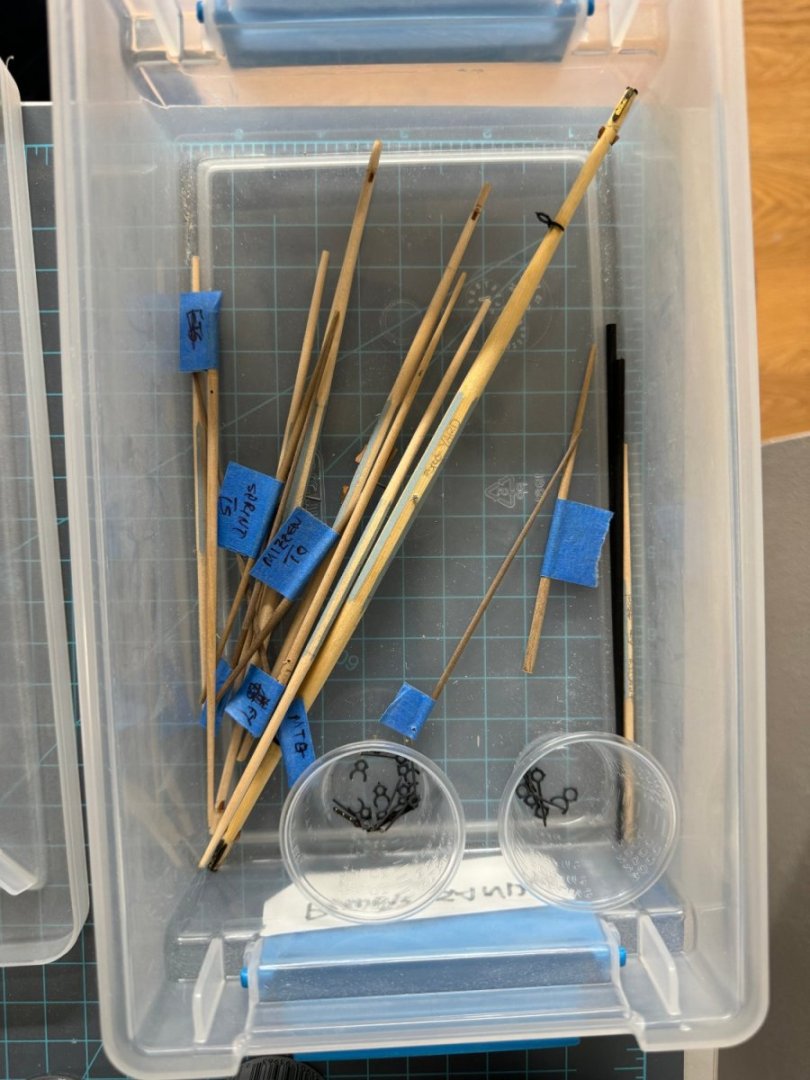
I have moved the spars to 'storage" since it appears that 4 and 5mm rigging blocks are hard to get from either Syren or Model Shipways. So back to working the hull and working on the main and fore masts until my "ship (rigging blocks) comes in".
- 422 replies
-
- 3
-
-
- Vanguard Models
- Sphinx
- (and 1 more)
-
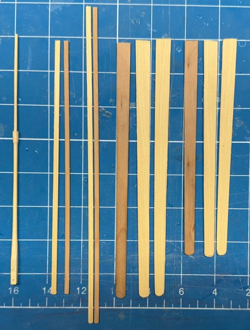
Thanks Thukyides - I made a cursory examination of the pear wood planks this morning and the half dozen I grabbed at random were only off by .05mm from the thickest to the thinnest. I will look themm all over before I start planking. Since all but the top half dozen (or so) rows are going to be painted (albeit white) I think i can find enough of similar color (and hopefully the same as the two rows supplied in the kit) to cover that area. If not I have a fairly large collection of pear wood I could cut my own planks from although I would hope that would not be necessary on a kit that cost close to $1000.
- 422 replies
-
- 4
-
-
- Vanguard Models
- Sphinx
- (and 1 more)
-
The first layer of the hull planking is done. I won't bore you with pictures as the planking is mostly covered with filler in preparation for generating a considerable amount of sawdust in the coming days. Given the experience I am considering doing the whole tick strip planking fan "stuff" for the second planking. I had to take some steps on this round that will not "do" on the next round in spite of much of the second layer is going to be painted. I want to assure myself that I CAN do a credible job when the chips are down. I got all the yard arms tapered and cut to size so in my spare time (sanding is hard work) I can start outfitting the yard arms and just for fun start building the other two masts and bowsprit.
- 422 replies
-
- 5
-
-
- Vanguard Models
- Sphinx
- (and 1 more)