HOLIDAY DONATION DRIVE - SUPPORT MSW - DO YOUR PART TO KEEP THIS GREAT FORUM GOING! (Only 27 donations so far out of 49,000 members - C'mon guys!)
×


cdrusn89
-
Posts
1,915 -
Joined
-
Last visited
Content Type
Profiles
Forums
Gallery
Events
Everything posted by cdrusn89
-
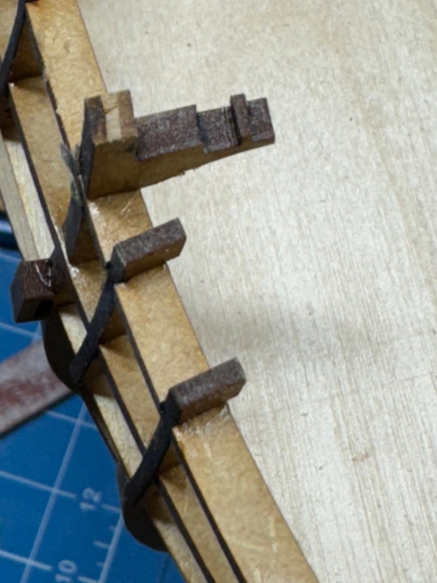
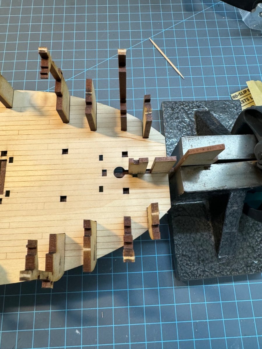
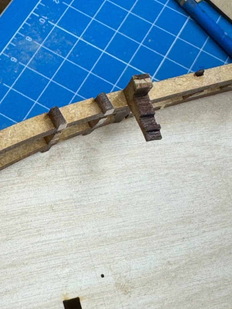
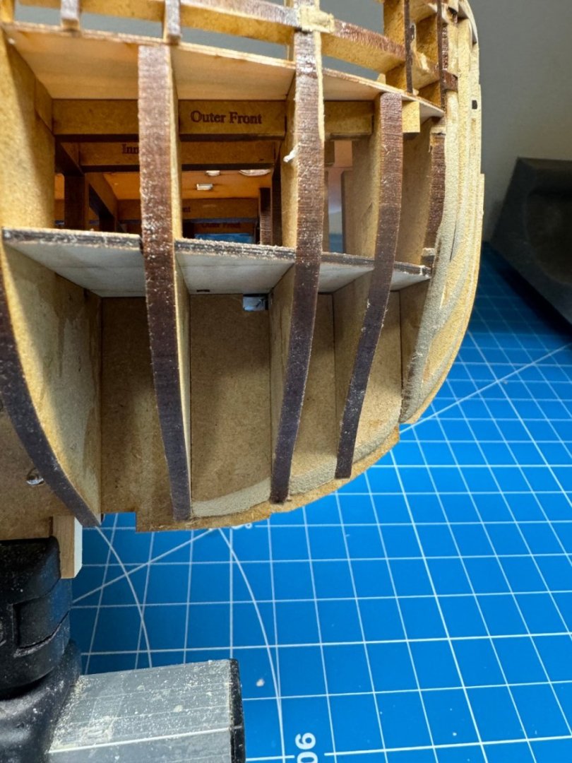
 Thanks Scrubby - it is taking shape much faster than Winnie did. But then I did not spend as much time cleaning off laser char. For the gun port frames (sides actually) I went back to the Amati holder but am keeping the foam one handy as it puts the hull in a better position (for me) to work on the gun deck. Gun port sides went is without much drama although I did manage to break the top part off two of them. I had a paint and glue party once all the frames were in place. Next are the filler pieces fore and aft. Don't ask me how I know but it is possible to get confused when switching from side to side and fore to aft to make two sets of fillers for the starboard side forward. Luckily there is plenty of "meat" on the carrier sheet so I was able to fabricate a new set to work from. Here are the starboard side fillers - port look pretty much (lets hope) the same. Bow could use some more work I think but this will all have to be faired again before planking so maybe close is good enough. So on to fairing the inside of the bulwarks. The first thing i noticed is that some (about half a dozen on each side) of the gun port frames stick out past the edge of the bulwark. These pieces are presumably glued to the top of the horizontal framing but it does not take much imagination to foresee one or more being tron off during the fair process. So I went around and sanded these back (carefully) before I started on the general bulwark "clean-up".

- 422 replies
-
- 5
-

-
- Vanguard Models
- Sphinx
- (and 1 more)
-
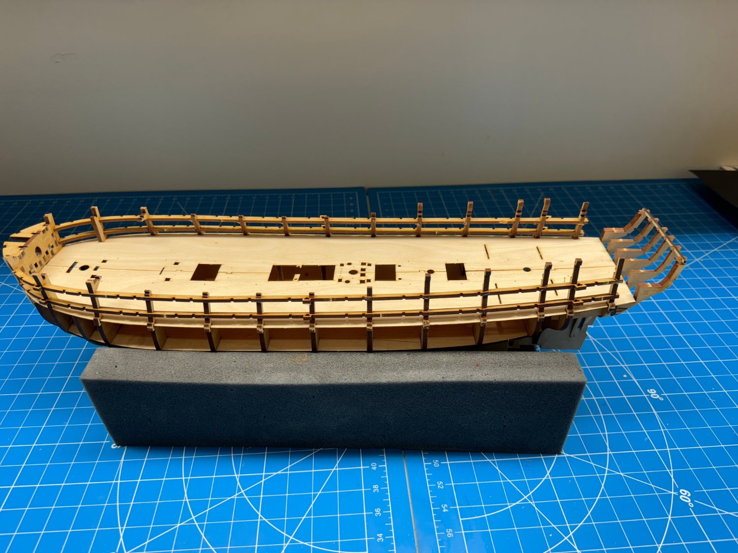
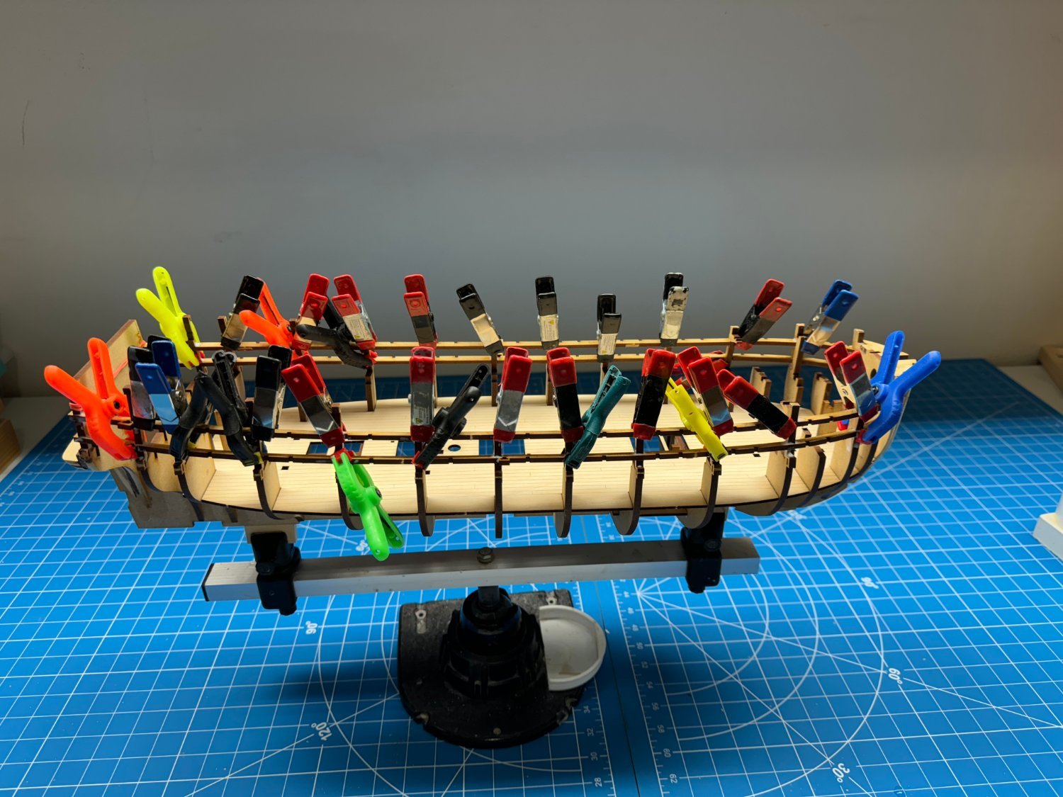
I revised my ship holding method for now as this foam seems to provide a lower work position to put the gunport frames on. I got the deck patterns on but not without having to enlarge the notches on both sides several times to get the two halves to fit together without overlap. I used the fit, pin and paint the underside method then turned it back upright and put some machinist blocks on the deck to hold things down while the glue set. I did manage to break one of the interconnections and almost the other but I am not sure this is really a problem.


- 422 replies
-
- 7
-
-
- Vanguard Models
- Sphinx
- (and 1 more)
-
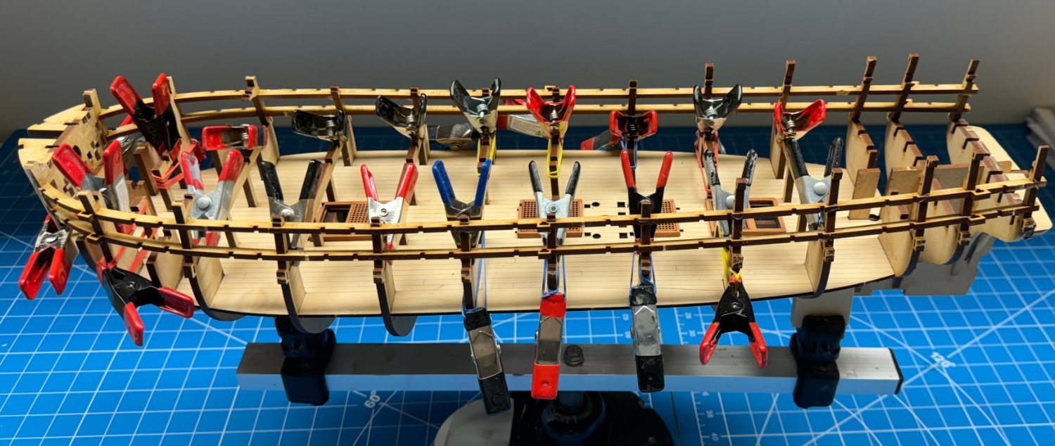
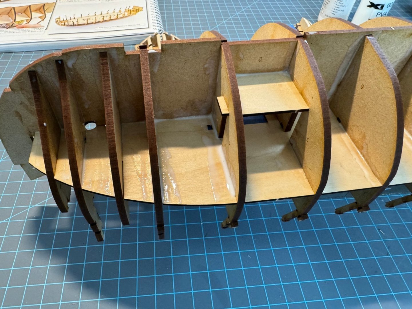
Gun deck support beams in place to dry. In some cases it took a few "taps" with a small hammer to make sure the beams were seated in the holes in the deck. I did take a 220 sanding stick very gently to the posts where they enter the deck as some were close to an "interference fit". Per the instructions on the one piece beams I used a clamp at each end to ensure the beam and the bulkhead were aligned. On the two piece ones in addition to a clamp at the top where the beam and bulkhead meet I stretched a rubber band around the deck beam support and bulkhead to keep it pressed into the bulkhead slot.


- 422 replies
-
- 5
-
-
- Vanguard Models
- Sphinx
- (and 1 more)
-
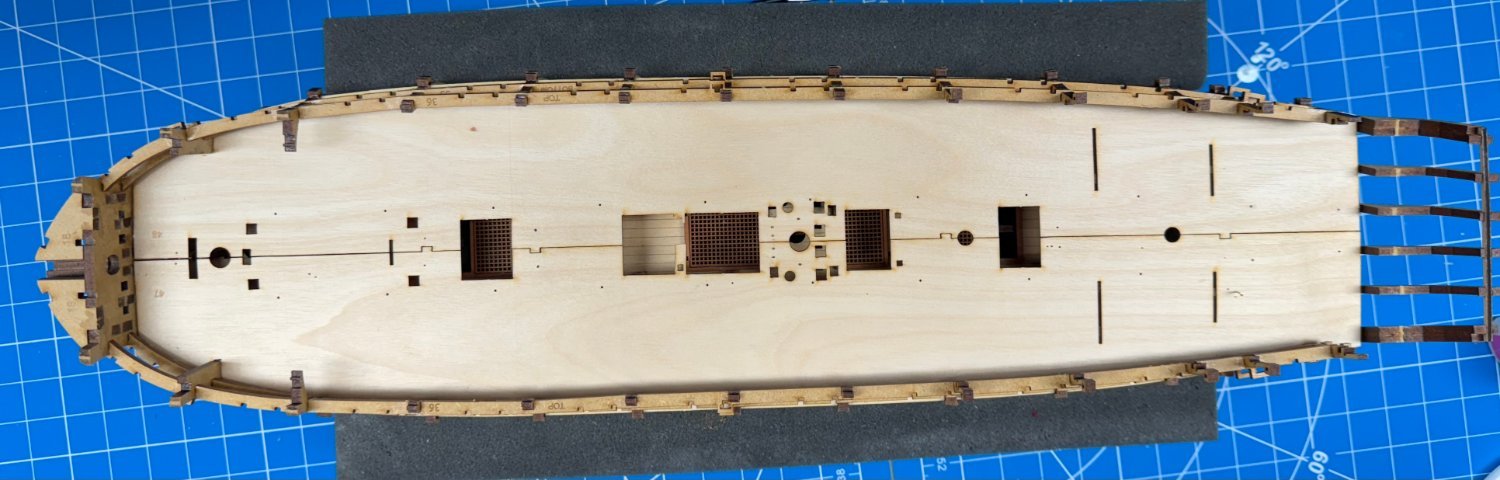
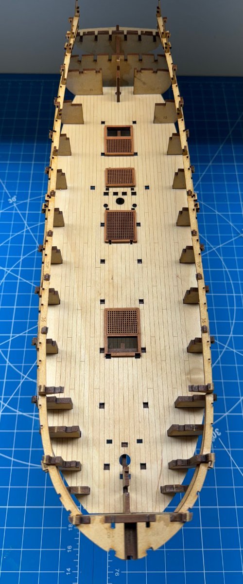
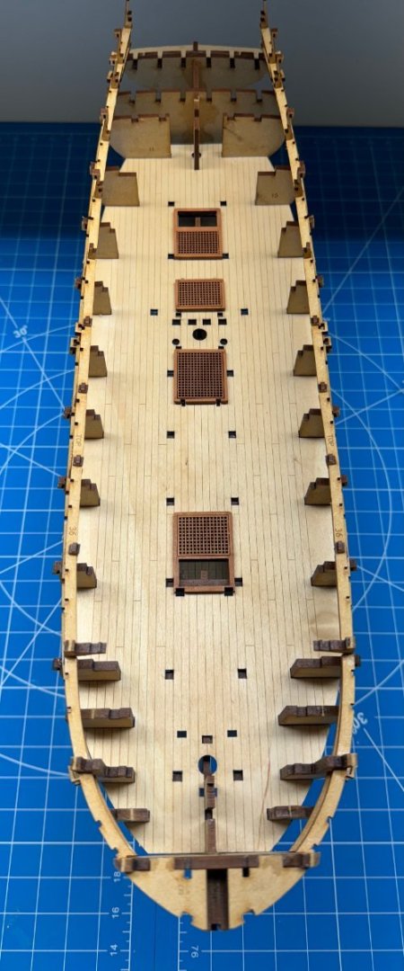
One coat of WoP on the deck and the gratings/coamings and now the coaming are glued down. Special care must be taken to both get the correct coaming/grating in the correct place (I initially confused the two with openings for ladders) and to get the "notches" clear of the holes (squares/rectangles) in the deck as if they are obstructed it will not be obvious until it is likely too late to be able to correct on the lower deck.
- 422 replies
-
- 6
-
-
- Vanguard Models
- Sphinx
- (and 1 more)
-
Thanks Kurt - I have WoPed decks before so am familiar with what it looks like on Alaskan Yellow Cedar (AYC), Boxwood and basswood but not on what ever this deck is made from. Looks pretty close to the AYC. Now that the gun port frames are providing some protection I will take a pass at some WoP before I install the coamings, which I will also probably WoP, out of habit.
-
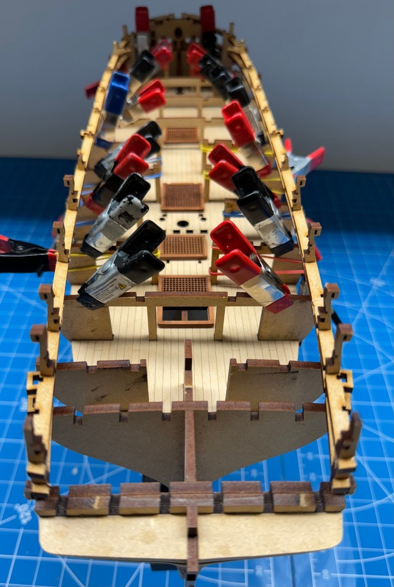
Upper and lower gunport frames in place and another glue painting party was held to round out the night. Several of the frames took a little persuading to lock in place and I was taking no chances of them pulling out while the glue dried. If I had enough clamps of the correct size I would have clamped ever bulkhead upper and lower but I did not have enough of the long plastic ones so I made sure they were placed anywhere I thought might be a problem. Sure beats cutting 100 or so pieces of stick wood and trying to get the angles and length correct so as not to distort the frames and still get the gun ports the right size/shape.

- 422 replies
-
- 5
-
-
- Vanguard Models
- Sphinx
- (and 1 more)
-
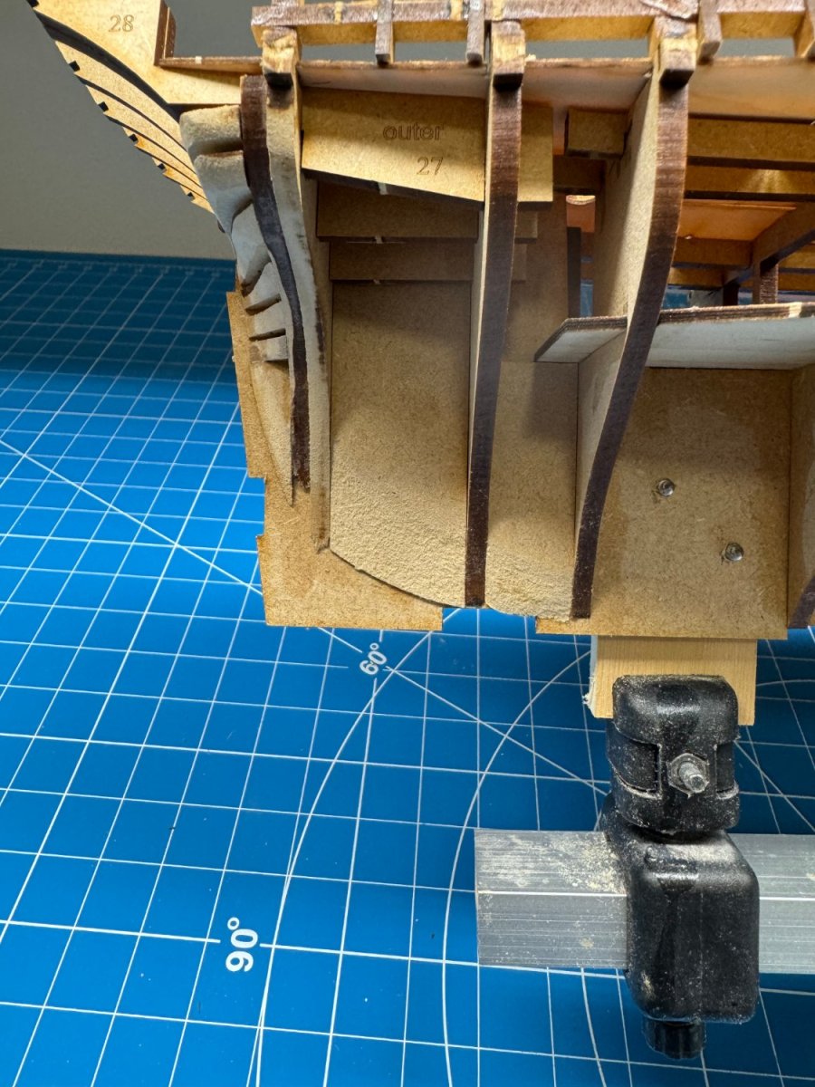
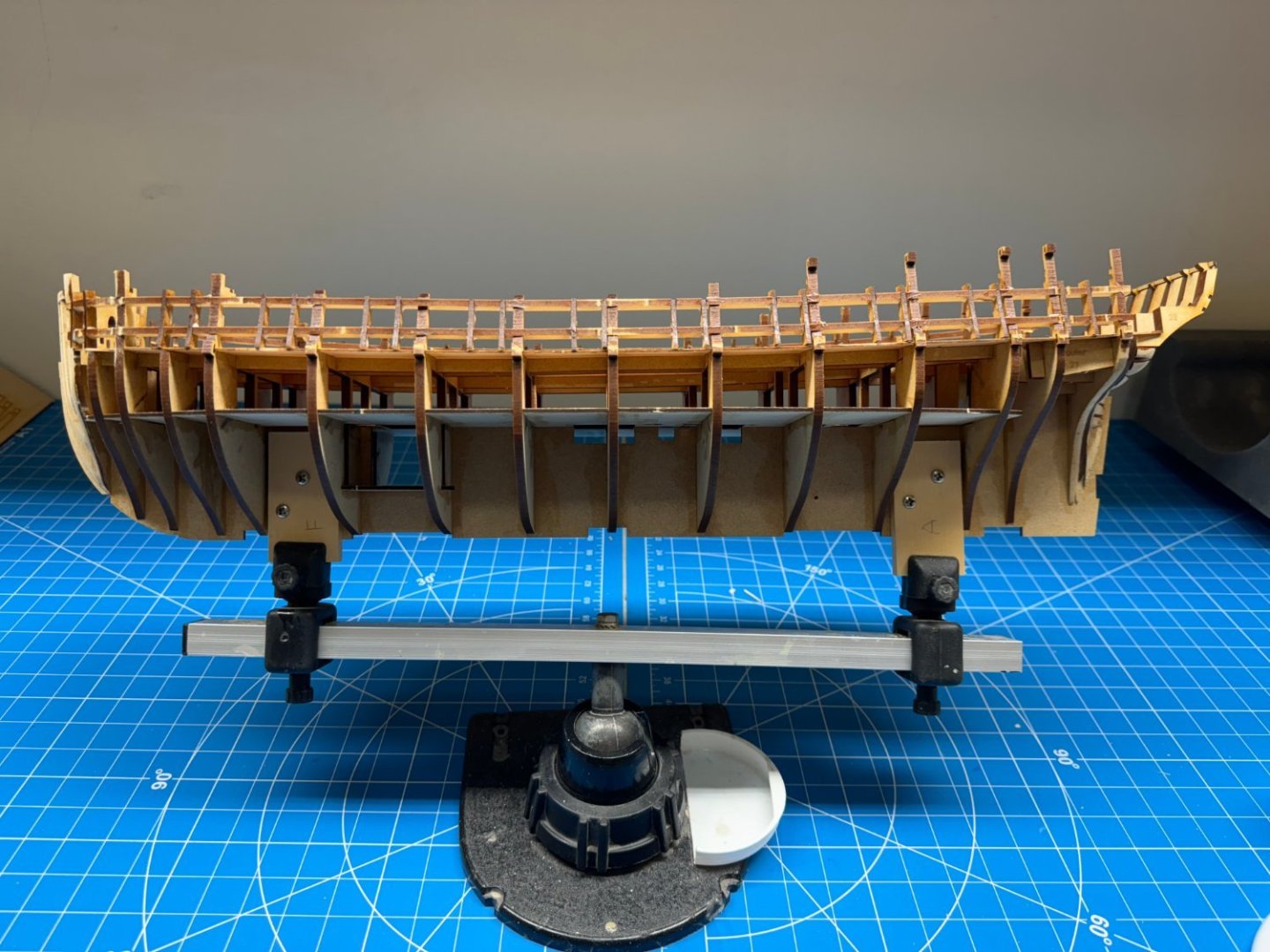
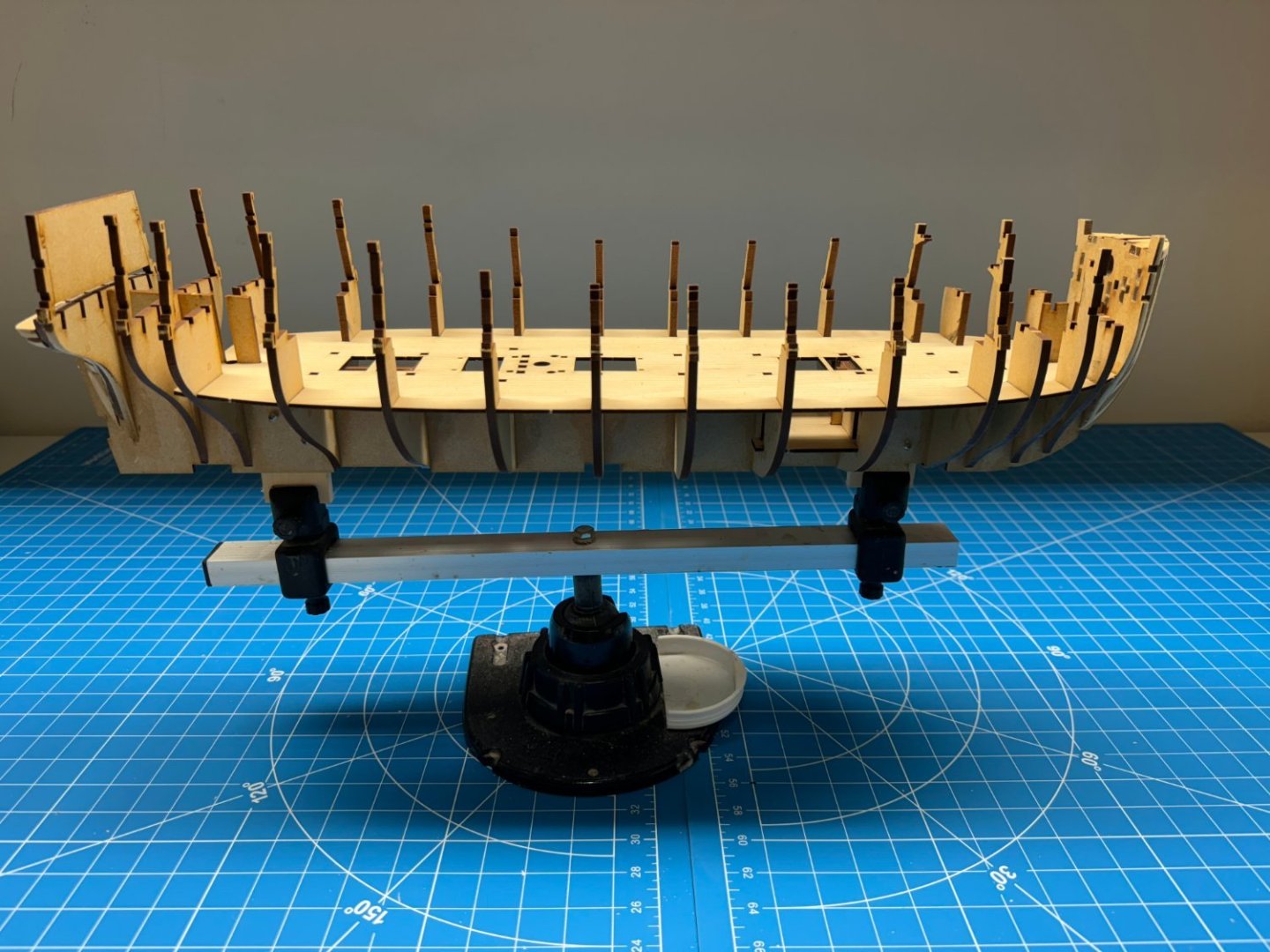
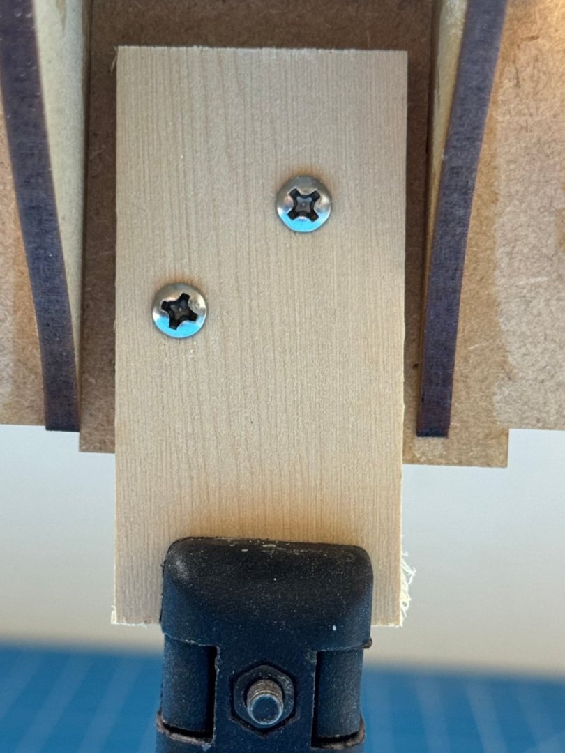
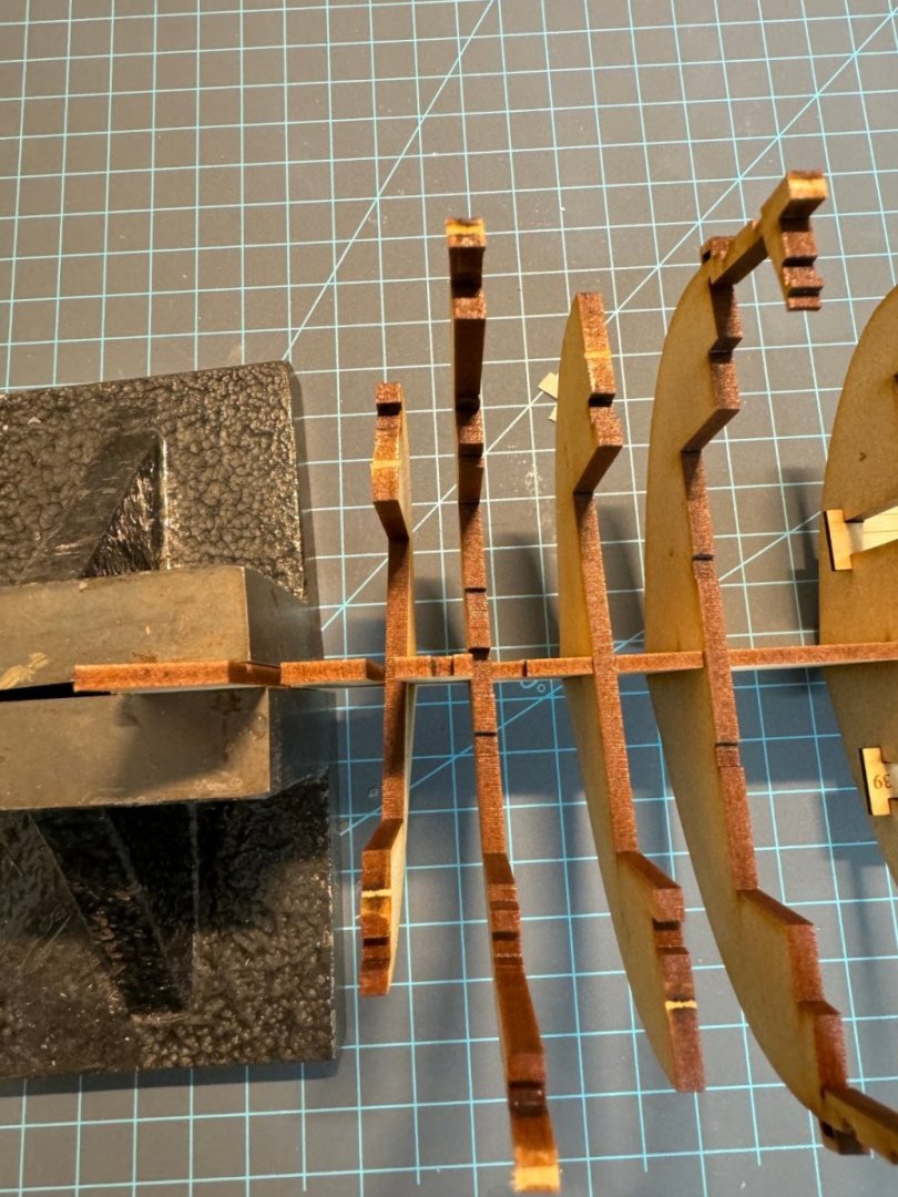
So the glue painting party is over and the glue dried for most of 24 hours. Now to "get on with the show". Much as I appreciate the provided building cradle I am kinda :married: to my Amati keel holder for this task. Unfortunately, at least at this point this I am reluctant to just grab a hold of the MDF center keel and "hope for the best". I have zero experience with keels of this material so I added "tabs" of cedar to two of the center sections to give the holder something to grip that is not really part of the center keel. Although the two screws have not done the structural integrity of the center keel any favors I am hoping that they can spread the load across a larger area an thus induce less strain to the center keel. On to the next step (#41).
- 422 replies
-
- 5
-
-
- Vanguard Models
- Sphinx
- (and 1 more)
-
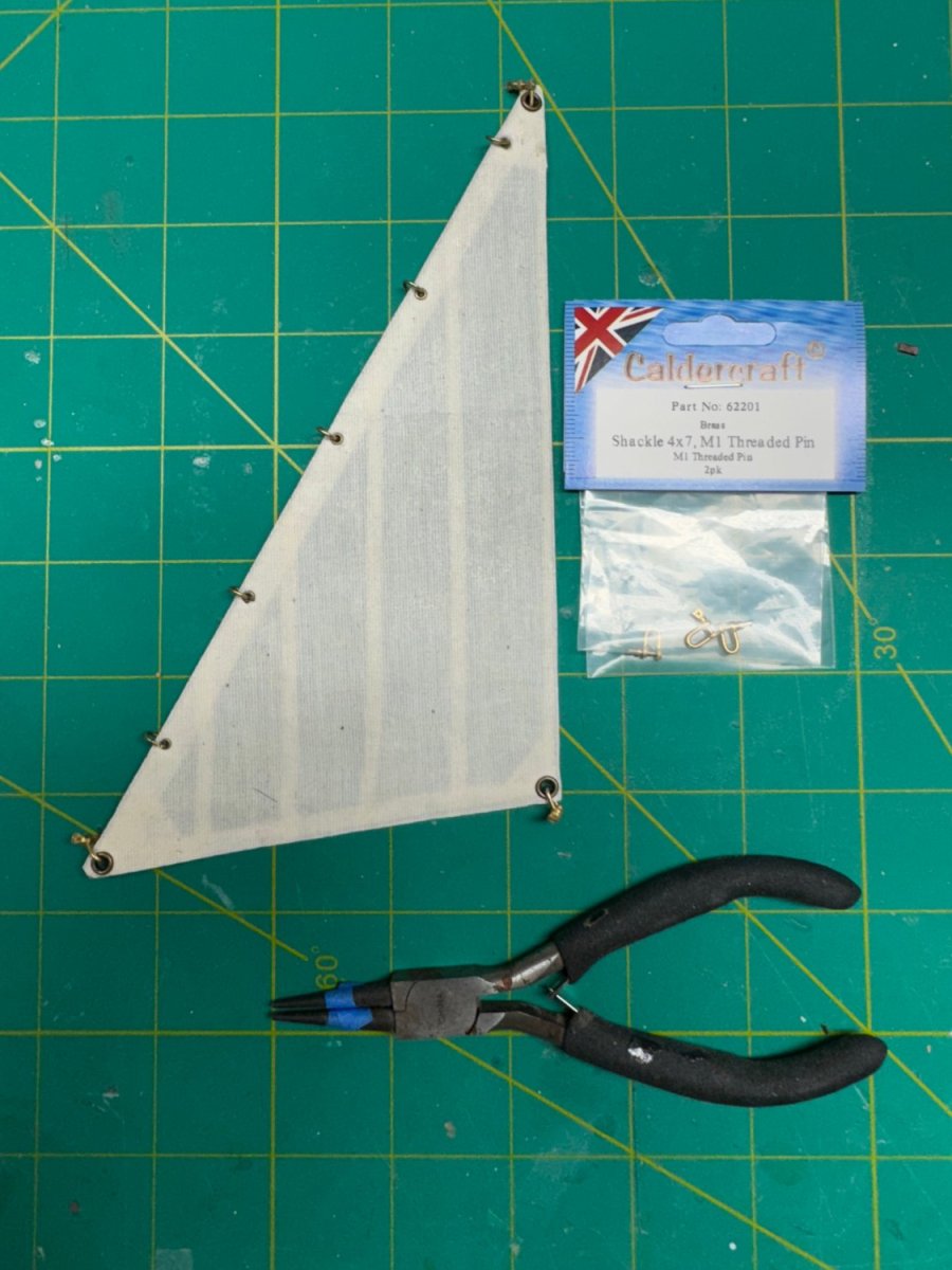
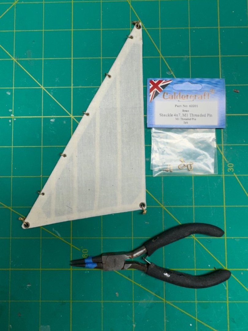
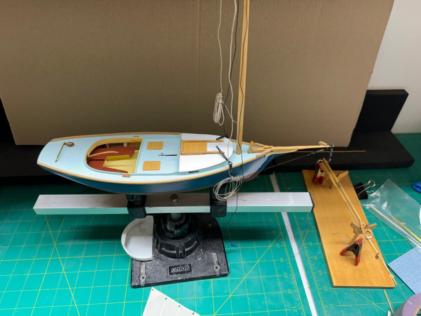
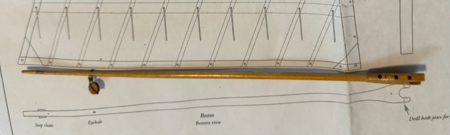
Jib is complete ready for hoisting. I had to use two different size eyelets in order to utilize the actual functioning shackles that i got from CalderCraft. They are too large but I am going to use them anyway. not sure when/if I will ever work at a scale larger (or is in smaller) that 1/24. Anyway I had 2.5mm eyelets that are almost big enough to get the shackle through. I did have to sand down the sides of the shackle a bit to get them through the eyelet but... So I put the 2.5's on the corners and the 1mm for the hanks. Speaking of hanks, I did not have any split rings the correct size (and the kit provided ones were too small) so I made my own from 1/32" brass rod. It took a couple of false starts until I got a size that would work. I made them with the round nose pliers shown below. The blue tape marked where on the nose I put the rod to get the correct (and consistent) size. So here is the completed jib ready to "fly". Attaching the sail to the mast/boom/gaff was no big deal except I recognized that my changes to the sail shape were not necessary. I was measuring the sail position too far aft on the boom. It really is just behind the jaw opening, not, as I thought) at the aft end of the jaws. So I have a boom/gaff that are too long. Too late to do anything now but I will know next time. So I attached the sail as best i could "under the circumstances) and once that was done stepped the mast. \Rigging is underway now and hopefully we are close to the finish line.

- 88 replies
-
- 4
-
-
- Muscongus Bay Lobster Smack
- Finished
- (and 1 more)
-
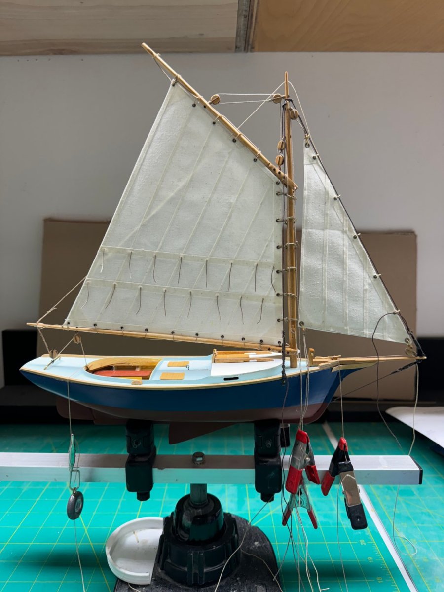
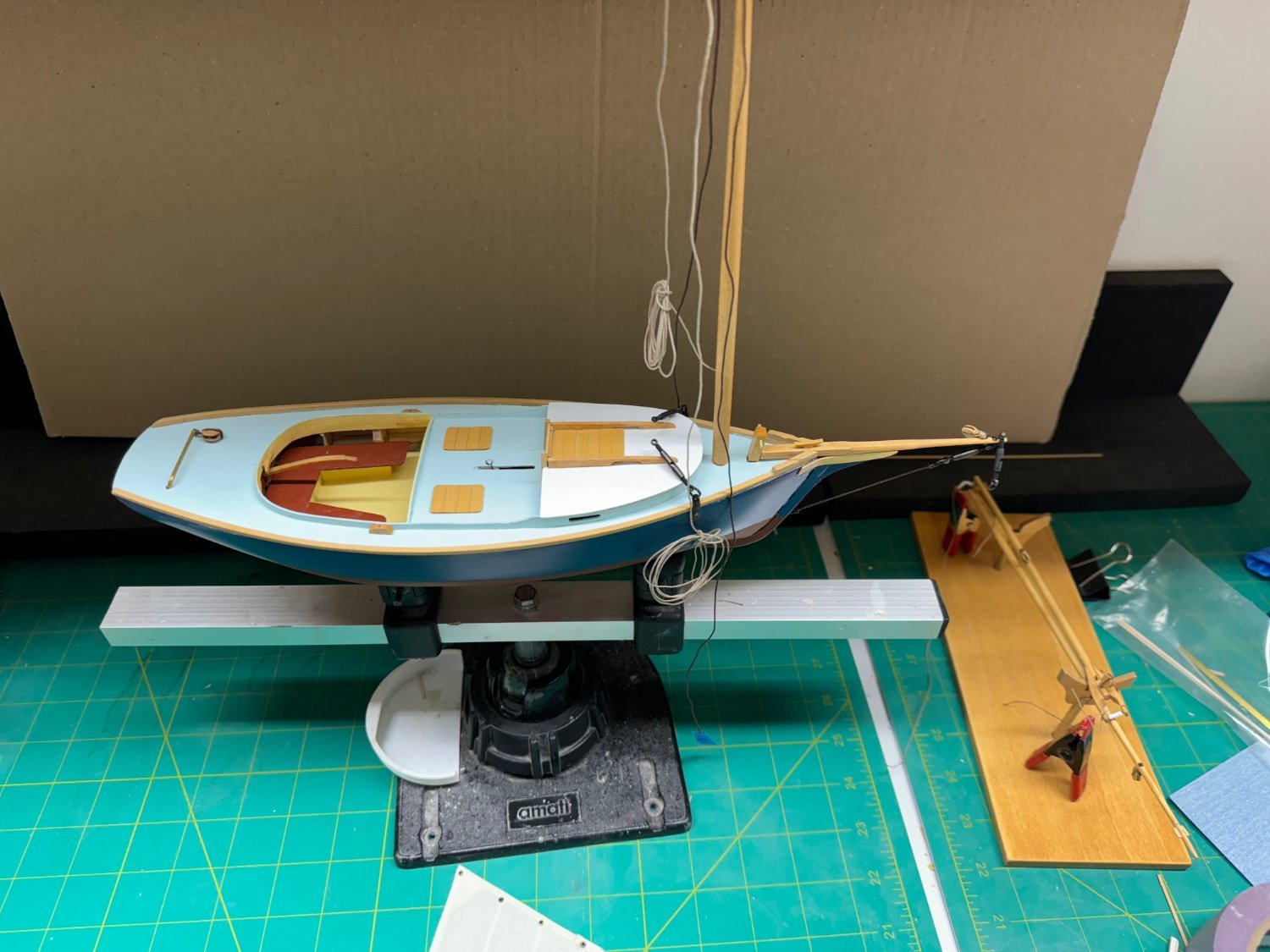
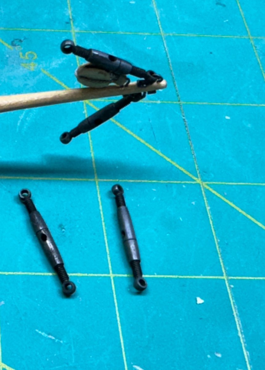
More progress - sail is finished - now to getting the hoops on. Tiller is installed (no the rudder does not turn - intentionally. Bowsprit is in place and jack stay reeved and tensioned. Chainplates are in place and the turnbuckles for the stays are ready. I had to make a new jib. I put the eyelets too far back from the luff and I did not have the correct size split ring to substitute for what was provided. And I put the stripes showing the panels going the wrong way - parallel to the luff instead of the leech. It will be dry and ready for eyelets installation in the morning. Rigging should start in earnest tomorrow.
- 88 replies
-
- 2
-
-
- Muscongus Bay Lobster Smack
- Finished
- (and 1 more)
-
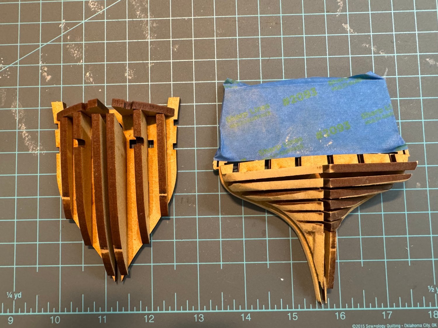
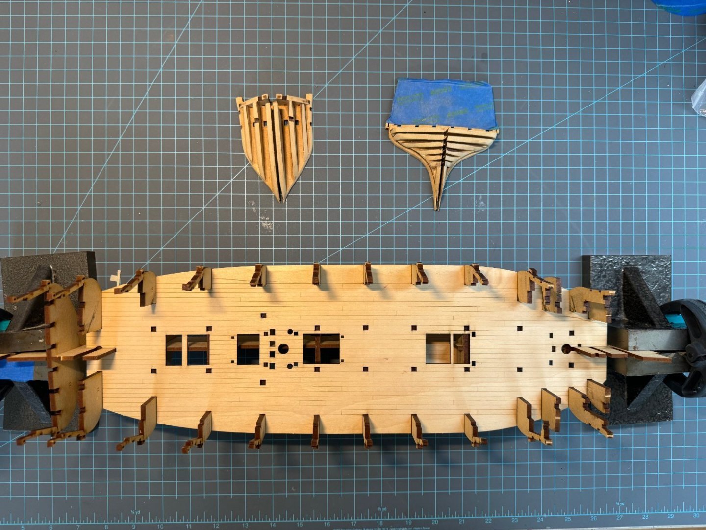
Thanks Theodoius - yes they are quite small but can be detailed to a surprising (to me) degree. I am. not looking forward to having to get the laser char off the oars again. I think next time i would just paint them completely. So with the bow and stern assemblies done (for now) it is time to get the bulkheads out of the carrier sheets and onto the hull. No great difficulties encountered. I would note that unlike many other kits I am familiar with the laser work here is really good. Typically there are only two tabs holding these huge and complex bulkhead pieces onto the carrier sheet. Makes getting them out really easy. I use a #17 Xacto knife and a small hammer - a few taps on the tab on each side and the bulkhead literally falls out. I started adding the bulkheads in the order shown in the instruction. I had not gotten very far (Bulkhead 1-1 and 2) before I noticed a problem. Clearly bulkhead 1-1 is not perpendicular to the keel. But I pressed on adding the remaining bulkheads per the instructions. The orlop deck (I thought the history said these 20 gunners did not have an orlop deck??) went in without incident - it fit very nicely. On to the lower deck - it took some finesse but it too went in and seated home. And low and behold the problem at Bulkhead 1-1 was resolved. Looks pretty perpendicular now. And i did not pay any particular attention to this are getting the lower deck on - I was more concerned with the bulkhead ears further aft. So here are the hull assemblies as they stand now: I used the machinist blocks and clamps to keep the keel steady while getting the lower deck in place. And now for the PVA painting festival.

- 422 replies
-
- 3
-
-
- Vanguard Models
- Sphinx
- (and 1 more)
-
Hey Kurt - I am about to slot the lower deck onto the hull (Step 36). Once the deck is down and the glue has dried is there a reason why putting a coat of Wipe-on-Poly would be a bad idea? I know it will be Well Nye impossible to actually see the deck but I did take all the char off the surface and probably can't help myself hitting with the WoP.
-
Both bow and stern templates have been faired. Again I am not sure what the "test" would be here other trying a fairing strip but given the limited area in play I am not sure it would prove much. I pretty much just sanded until all (or almost all) of the laser char was gone as it looks from the picture in the instructions.

- 422 replies
-
- 2
-
-
- Vanguard Models
- Sphinx
- (and 1 more)
-
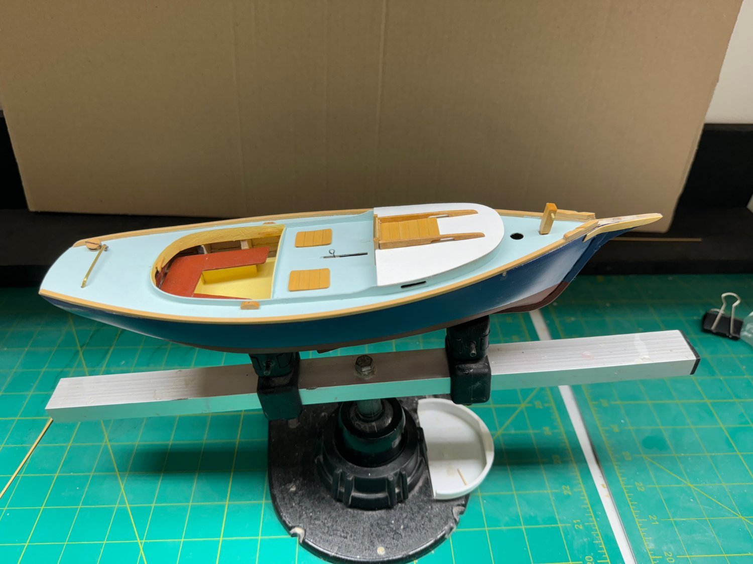
Making some progress. Have the cabin hatch and sliders, tank covers, Sampson post (the photo exaggerates the forward slope - it may well be to much but I will see how it looks on the display stand before taking action. Chainplates are next. The sail is finished except foe the reef straps on the other side. These were cut to 1" and I may leave them that long. Trying to trim them (and get them all the same) without pulling them off the sail seems not to be worth the potential damage. I am not sure why the instructions are this way. I am not sure a 3/4" piece would be any harder to handle than 1" but...


- 88 replies
-
- 3
-
-
- Muscongus Bay Lobster Smack
- Finished
- (and 1 more)
-
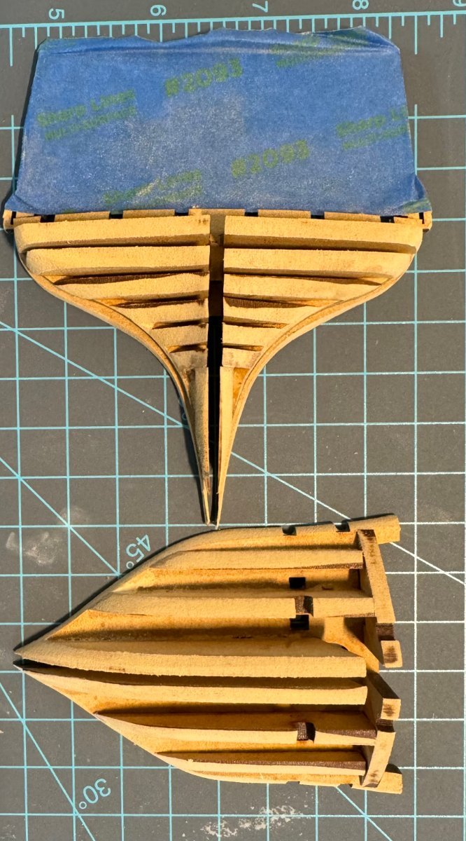
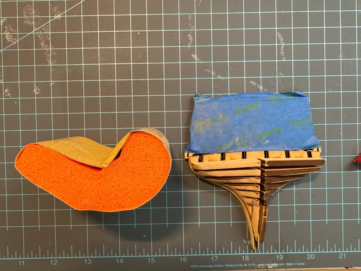
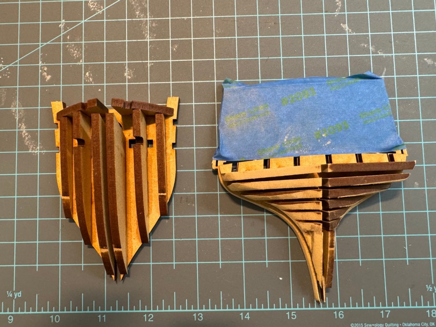
Sp it is time to build the hull! So I got the bow and stern "assemblies" together without too much trouble although I was scared to death I would glue the formers to the keel that I only put glue on the tabs until I got Bulkhead 12/13 off the keel. Then I painted every junction with diluted PVA. So here is what they look like. I have sanded one side of the stern. Pay no attention to that white glue on the cutting mat - I will clean that up before I quit for the day. I did not use any rotary tools to do what you see on the stern. I did use a Soft-Sander with their 220 grit paper (which is more aggressive than any 220 paper I have seen so far). The shape of the sanding block (and it is flexible (sort of) allowed me to easily find a contour that matched what I (think) I needed to do although with only a picture to go by I might be way off. I think that side needs a bit more work - what you see took about 15 minutes. The Soft Sanders (this is not a commercial - I am pretty sure i saw these on MSW somewhere) come in a variety of contours and since we are not sanding autos or boats you will get half a dozen sanding pads out of one "stick". Hopefully I will have both bow and stern done tonight.

- 422 replies
-
- 3
-
-
- Vanguard Models
- Sphinx
- (and 1 more)
-
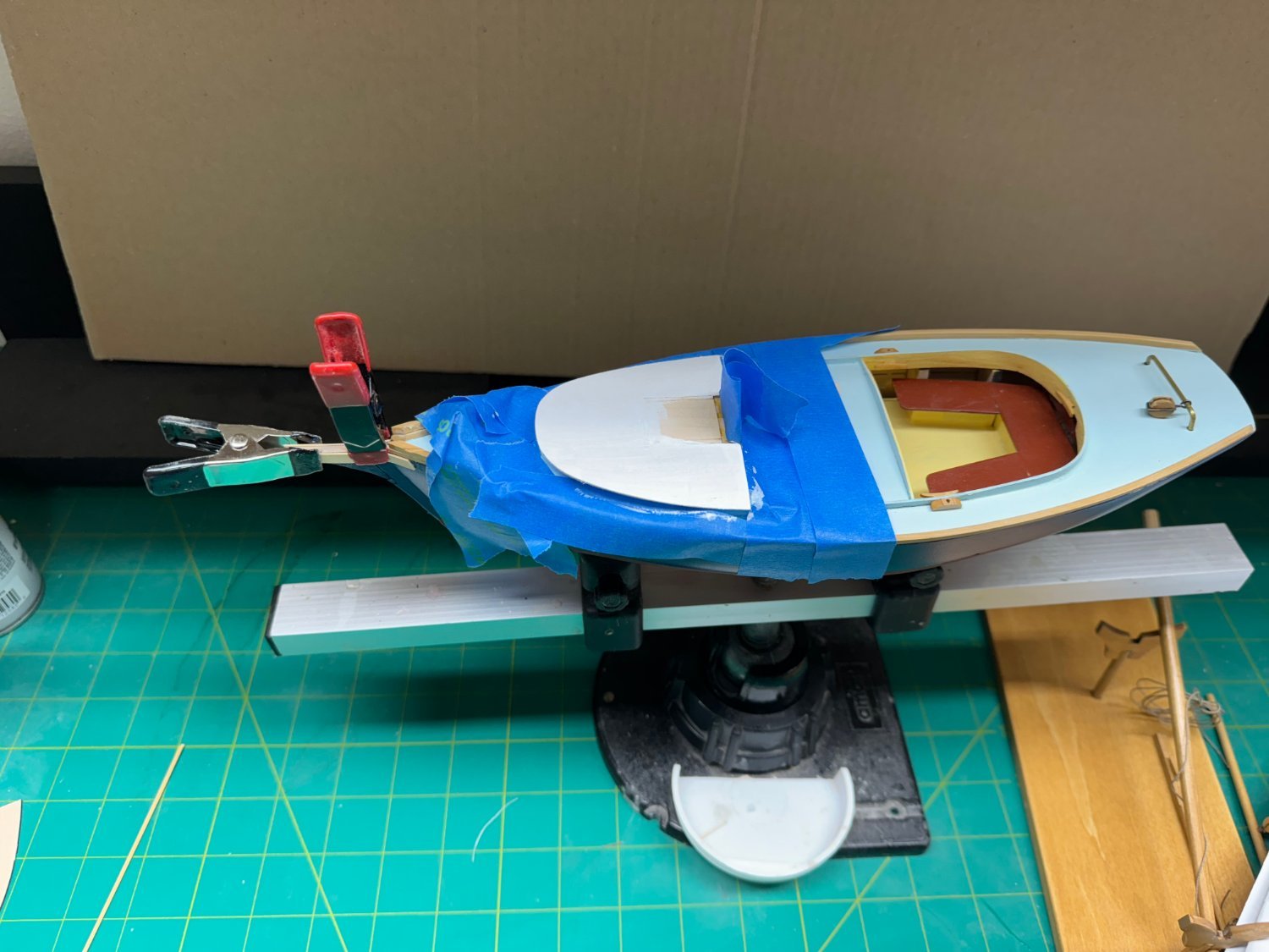
Thanks Major - getting the 1mm ones has so far involved buying the set (tools and 100 eyelets, 25 in each of four colors -less than $12 including tax). Maybe somewhere other than Amazon you can get just the eyelets, but then 25 is all I needed for the main and if the jib is in a slightly different color - oh well. Meanwhile back at the hull some more progress and some not so progressive moves. First, the instructions warn that the trailboards are fragile - I completely agree having broken both (shipbuilding god owes me another $1) of them trying to get them installed after painting. I tried to piece them together but was never able to get the joint to disappear - maybe I should have opted for the scroll work to hide the joint but... So anyway I fabed some new trailboards from boxwood, soaked them and clamped them in place to dry. I will probably finish them natural rather than try to paint them. And I installed the cabin roof and painted it white. - going to be at least three coats based on recent experience with this paint. I am going to have the sliding cover in natural boxwood and the slides are from the kit, stained Fruitwood and varnished (WoP) so they should be a close match. All the cleats, oar locks and traveler are installed now. Display stand and all the spars are ready. I fabed and blackened the "chainplates" but can't install until the roof paint job is finished. Need to "build" the jib now that the main is done.

- 88 replies
-
- 3
-
-
- Muscongus Bay Lobster Smack
- Finished
- (and 1 more)
-
Thanks Gregg - I take no credit for originality but to be honest I do not remember where I first saw this. As I said I used it on the 1/35 scale Endeavour and it worked out fine.
- 88 replies
-
- 1
-

-
- Muscongus Bay Lobster Smack
- Finished
- (and 1 more)
-
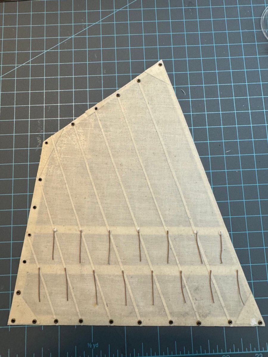
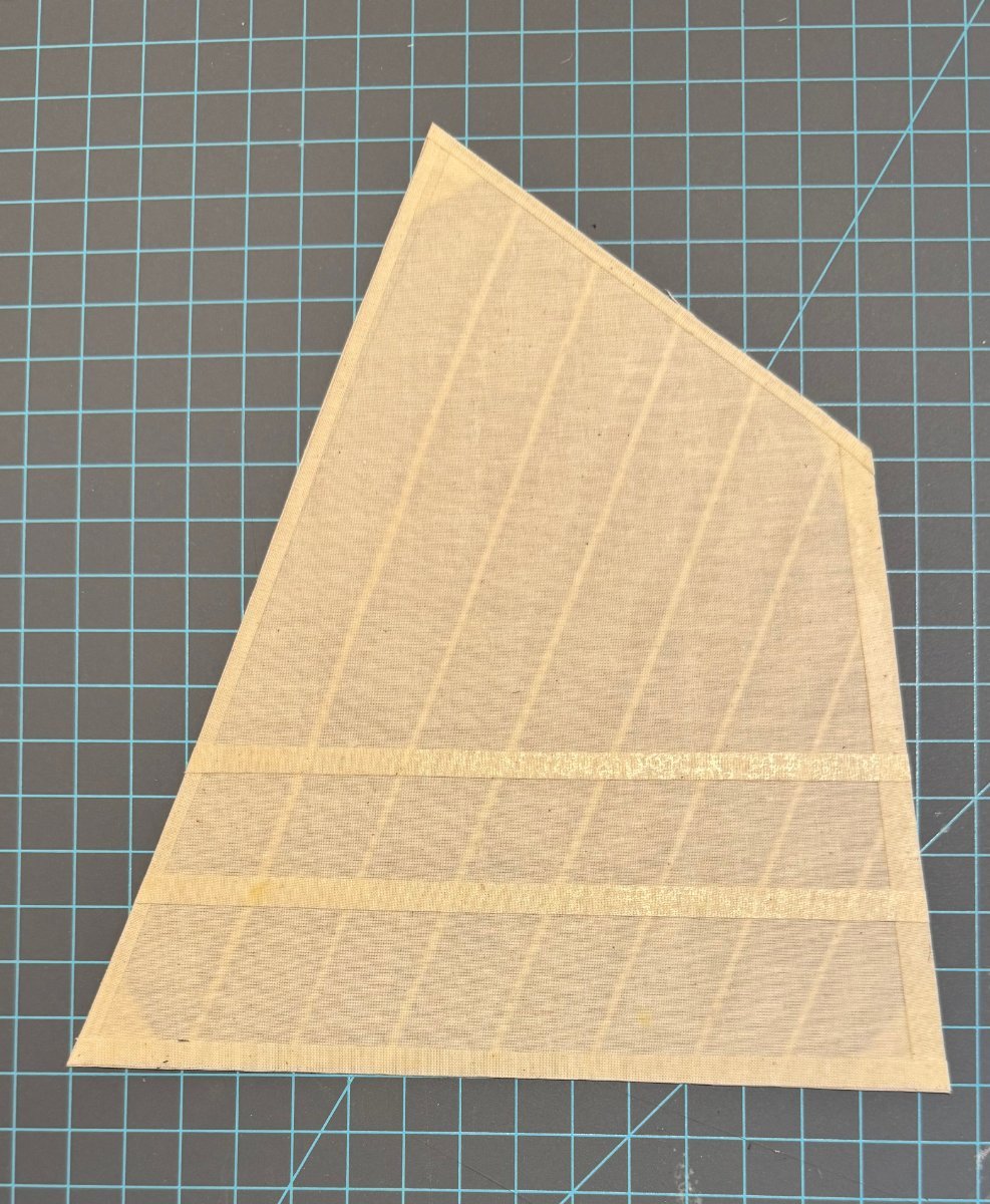
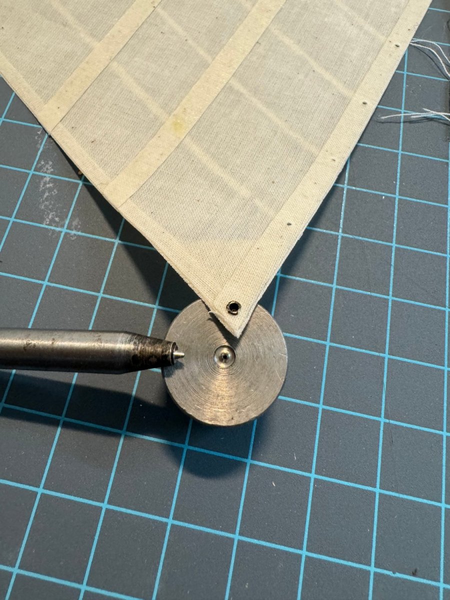
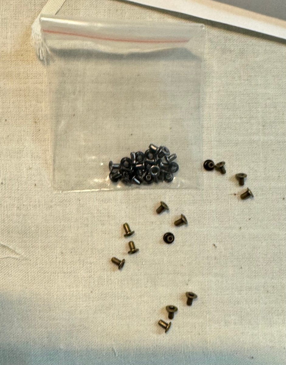
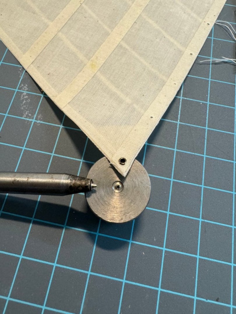
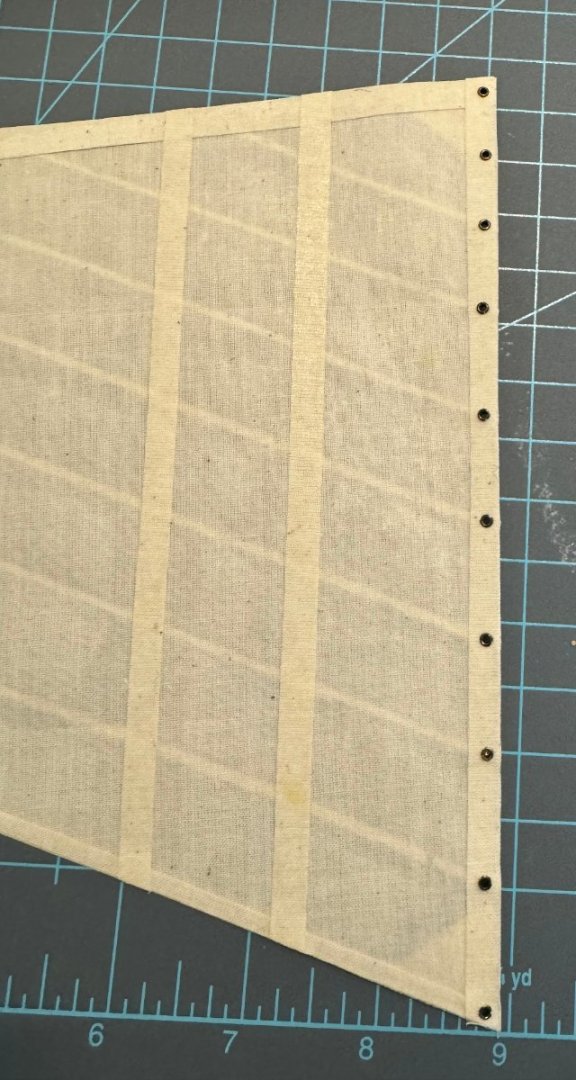
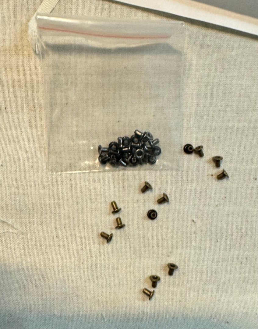
I managed to get the sail "manufactured" without significant issue, except a little dirt seems to get entrained in the glue no matter how much I cleaned the surface beforehand. Now to the "holes". On a previous build at a slightly smaller scale (1/35) I used metal eyelets instead of just "holes" in the sail. Less chance of to hole not staying the drilled size or the line pulling through the material if it is pulled too tight. Plus it is pretty much what the "real" boat had. These are 1mm eyelets (from Amazon, although you have to look carefully through the "1mm eyelet" search results to actually get 1mm eyelets). This set includes the tools necessary to install them too. Since I can't really measure the inside diameter mof the eyelet easily I measured the outside diameter of the "barrel" at 1.6mm so a wall thickness of 0.3mm would have the interior opening at 1mm or about 1" at full size. Certainly not too big. First you need the hole and for that they provide a "punch". I used a scrap piece of wood under the sail while I punched the holes. Sometimes it took several "hits" to get all the way through as there are three or four layers of "sail" in some places The "plug" is held in the punch until enough accumulate then they fall out a slot in the tool. You insert the eyelet (not that easy, I use an awl to put the eyelet on then use that to get the eyelet through the hole. The eyelet is then placed on the anvil and the other end "mushed over" by striking the end of the "mushing tool" shown on the left below. This eyelet has already been mushed but you get the idea. Using a small jewelers hammer it takes five to eight strikes to get a proper "mush". The real trick (for me) is making sure the eyelet is properly seated on the anvil. I put the mush tool on the eyelet and try and move the anvil. If it is seated properly it should not move, otherwise relocate the eyelet and try again. Here is the bottom of the sail with all the eyelets installed.


- 88 replies
-
- 4
-
-
-
- Muscongus Bay Lobster Smack
- Finished
- (and 1 more)
-
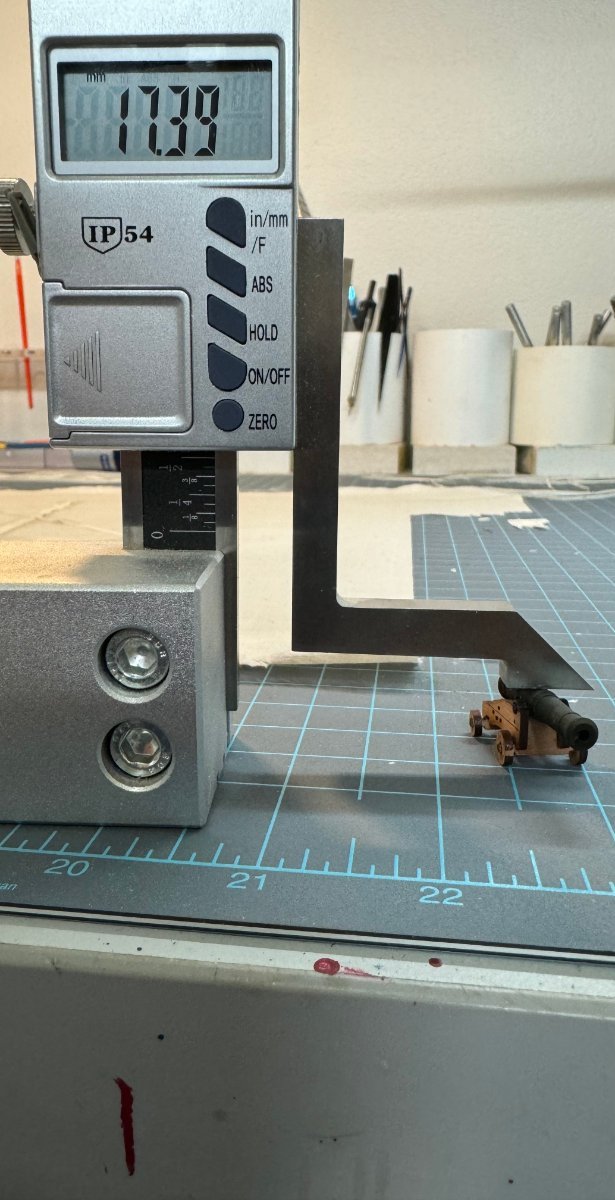
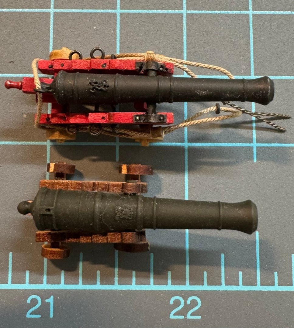
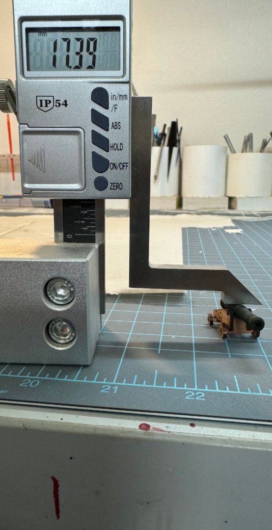
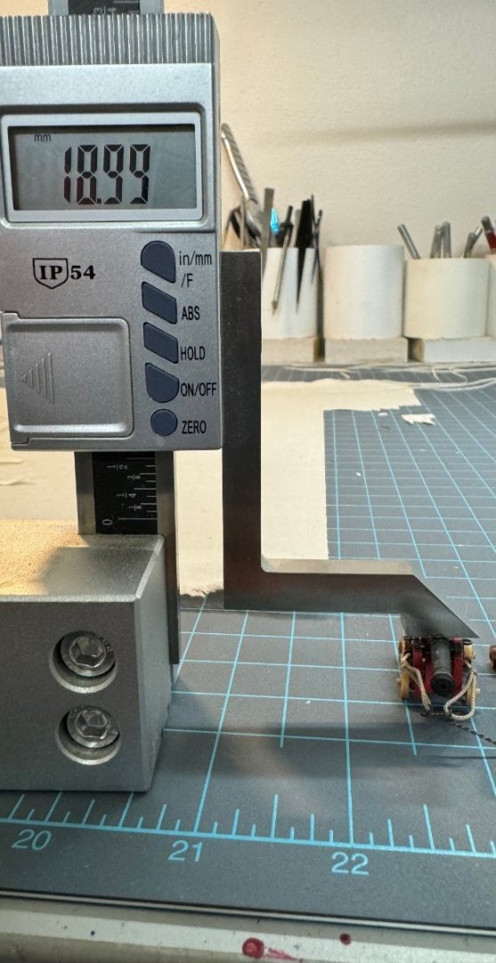
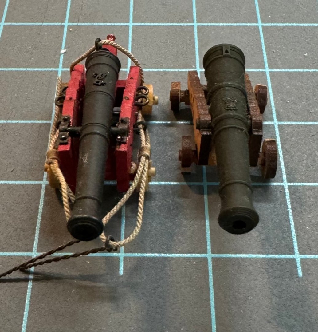
So I decided to see about the already constructed cannon that I have "in storage". As I recall these were supposed to go on the Confederacy (I did not like the Model Shipways cannon for some reason) but were too tall to fit through the gun port. (and I never thought about sanding the wheels down a bit) And as it turns out I have exactly twenty of these all ready to go, including the breeching tackle. I went ahead and built one of the cannon that come with the Sphinx kit (which I might add are somewhat different from what Vanguard sells on their site - at least what they were selling last year). Here they are side by side: Overall the ones I have (which are Syren Ship Model Company products by the way) are about 1/8" longer. The cannon is narrower although the Syren guns are "advertised" as being 12 pounders while Sphinx carried nine pounders. Since the issue on Confederacy was height I used my handy dandy height gauge and here is what I found: The Syren cannon are about 1.6mm (aka .065") taller. The real question that I will not be able to answer for some time: is this too tall?? End result I wait until I have a gun deck to measure before I build any more cannon. On to the hull. 😃
- 422 replies
-
- 2
-
-
- Vanguard Models
- Sphinx
- (and 1 more)
-
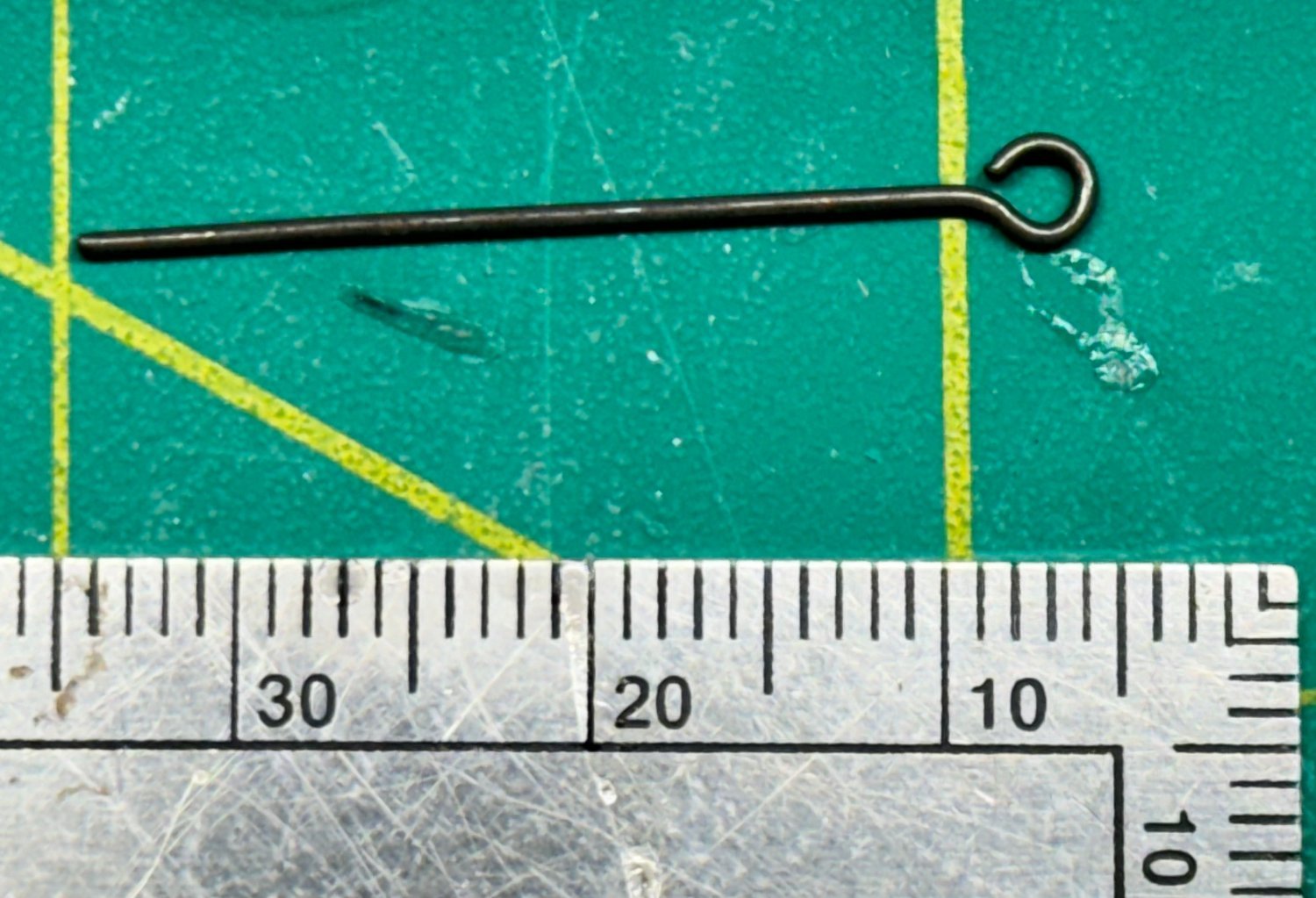
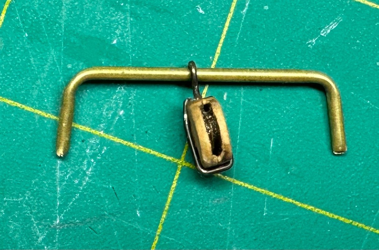
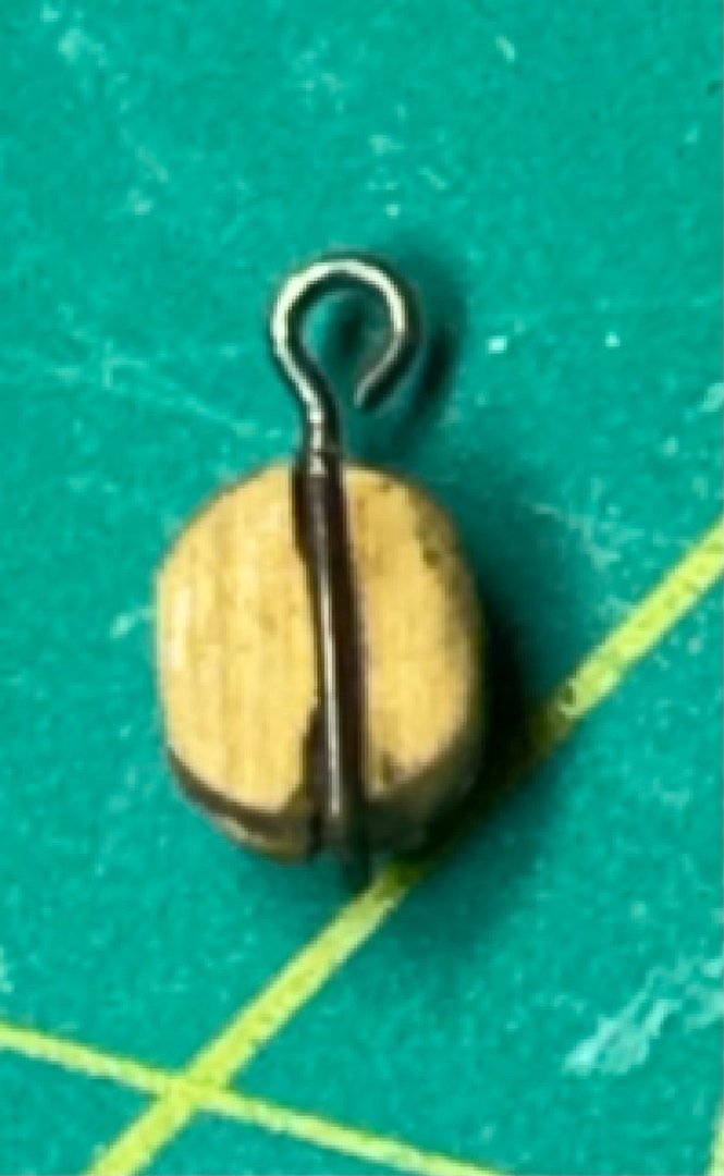
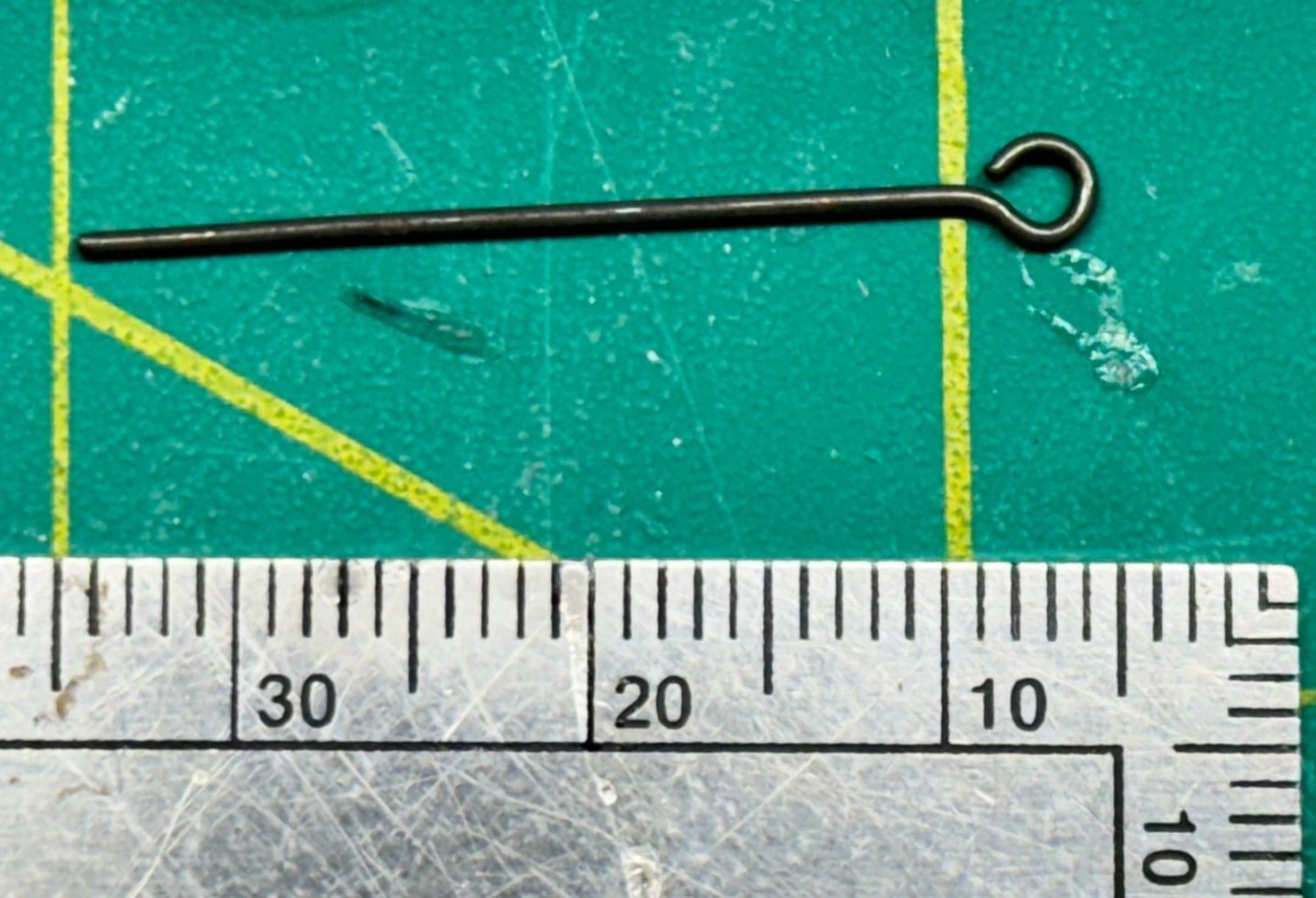
While waiting for the glue to dry on the sail material I tackled the traveler and associated block. I did not see a way to avoid using metal stropping on this block. A rope eye on the traveler would not last very long. Not a big fan of the technique in the instructions (mostly because I have never been able to make it work as nicely as the instructions). So I tried another tack. In my pile of material I have eyebolts which I believe I got from Model Shipways several years ago (pre-Pandemic). A quick look at their website does not show these now; they are about 1 1/8" long. I drilled a hole in one end of the block just big enough (#70) to fit the eyebolt shank. I drilled the hole deep enough to pass through the channel where the rope has to run but not all the way through, not quite half way. I cut the shank of the eyebolt so just the eye was exposed, inserted the eyebolt and added a drop of thin CA. Then I used a #68 drill to drill through the rope channel that is now blocked by the eyebolt shank. Hopefully there is enough material in the upper part of the block for the thin CA to hold the eye in place. Another drop of thin CA can't hurt. Then I bent the shank at was removed in a "U" and glued it on the sides of the block. I had a old piece of 1/16" brass rod (all the shine was long gone) and slipped the eye over the rod after it was bent to the shape in the instructions and check fit on the hull.
- 88 replies
-
- 3
-
-
- Muscongus Bay Lobster Smack
- Finished
- (and 1 more)
-
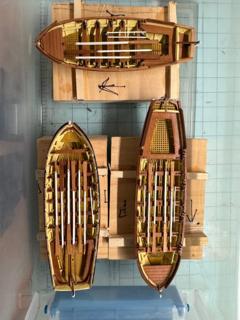
Pinnance is finished and has joined its cohorts in the Sterlite storage case where they will await the completion of the model.
- 422 replies
-
- 4
-
-
- Vanguard Models
- Sphinx
- (and 1 more)
-
Thanks - I will be glad to get these behind me. Am considering doing the cannon next instead of the "real" ship. I really hate stopping the hull construction in the middle to open the armory. I may have some cannon that will fit already made from a previous error in not checking sizes accurately enough but will get the Pinnance finished then move on to the cannon or the hull.
- 422 replies
-
- 2
-
-
- Vanguard Models
- Sphinx
- (and 1 more)
-
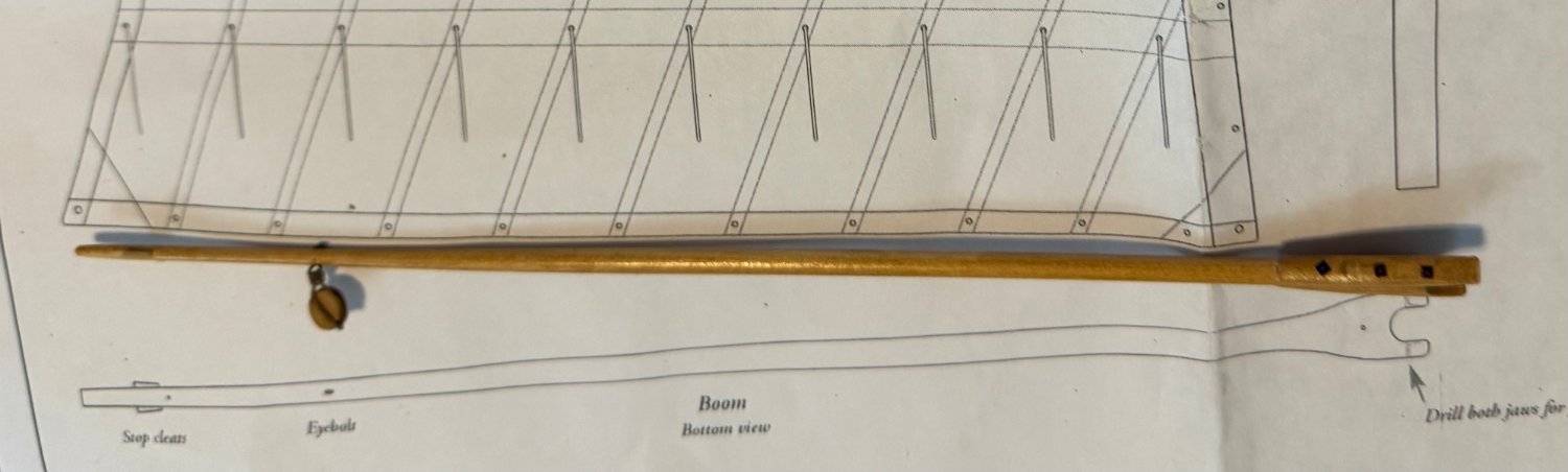
Time to make sails while the hull gets a new paint job - with the beakhead on this time. I looked at the sail plan and "on a lark" laid the boom up against the sail. Wow - the sail looks to be a panel too long. If the stop cleats are to hold the outer end of the sail, as the pictures in the instructions show then this sail would be way too big. I checked the boom against the drawing and it is "spot on" so I will cut the sail one panel shorter than the plan. If I cut the main one panel shorter I may have to shorten the gaff a bit of at least move the stop cleats forward a bit. Glad I measured and did not just cut to the plan. Could have been worse, sail could have been too small, then cutting first would have been a REAL problem.
- 88 replies
-
- 1
-
-
- Muscongus Bay Lobster Smack
- Finished
- (and 1 more)
-
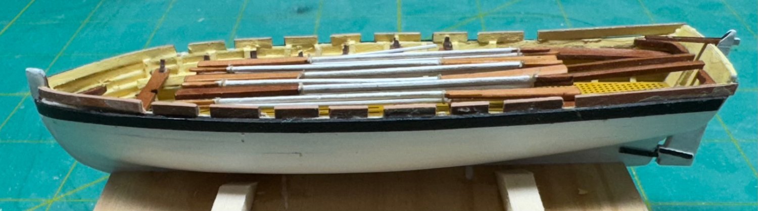
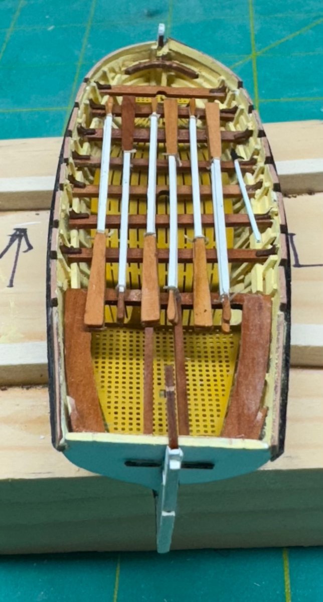
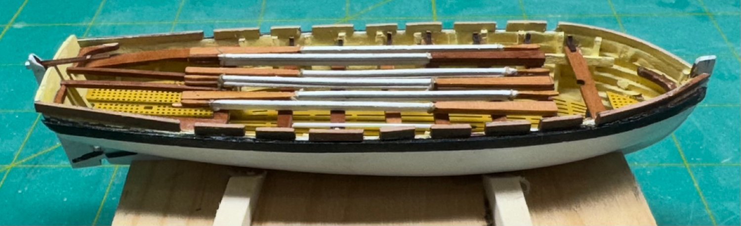
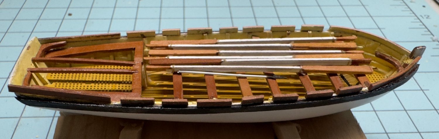
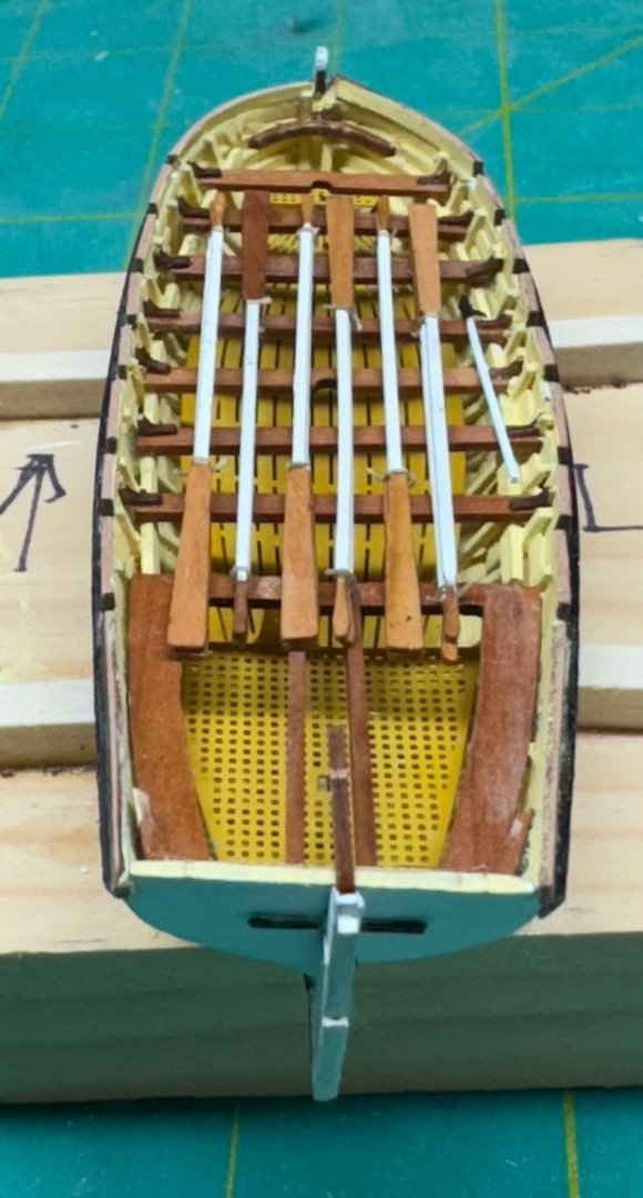
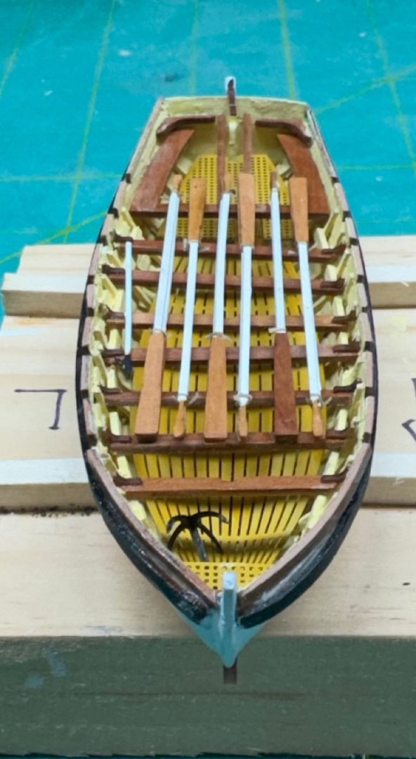
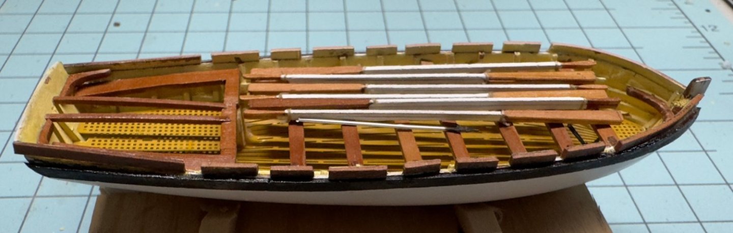
Launch is FINISHED!!! I did not use the "extra" tiller. It was one less thing to do and I am. not sure what it would add. Pinnance has the wales now so the seats and the rest is "coming soon". I think the oars successfully "hide" the problems and extra support I added to the after seat piece(s).


- 422 replies
-
- 8
-
-
- Vanguard Models
- Sphinx
- (and 1 more)
-
Launch almost complete. Some touch-up on the inside and outside of the planking defining the oar lock locations and gluing the oars and boat hooks down and then on to the Pinnance.
- 422 replies
-
- 4
-
-
- Vanguard Models
- Sphinx
- (and 1 more)
-
Here they are after blackening and with the larger set for the shrouds. I used these on my 1/35th scale Endeavour and they did not look out of scale there so here at 1/24 they should be okay. I got them from the ShipWrightShop.com in the UK so shipping is expensive and the small ones are about $3.50 each (5.40 UK Pounds for two).

- 88 replies
-
- 3
-
-
- Muscongus Bay Lobster Smack
- Finished
- (and 1 more)