HOLIDAY DONATION DRIVE - SUPPORT MSW - DO YOUR PART TO KEEP THIS GREAT FORUM GOING! (Only 72 donations so far out of 49,000 members - Can we at least get 100? C'mon guys!)
×


cdrusn89
-
Posts
1,915 -
Joined
-
Last visited
Content Type
Profiles
Forums
Gallery
Events
Everything posted by cdrusn89
-
 Steve, Niagara was a fun build except for all that rigging. I think I spent more time on that than the rest of the build. Best of luck - if you have any specific questions I will do my best to answer them.
 -
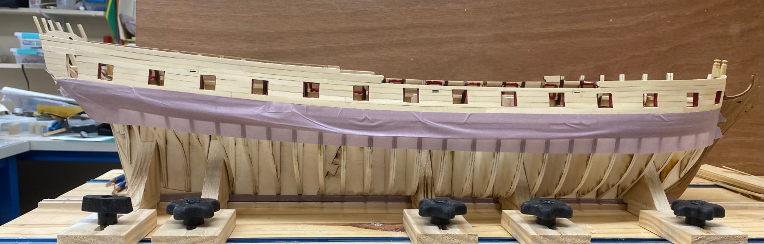
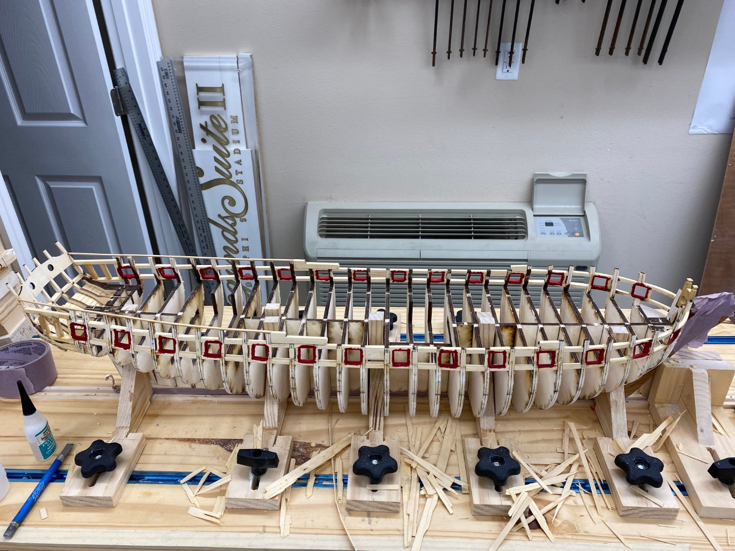
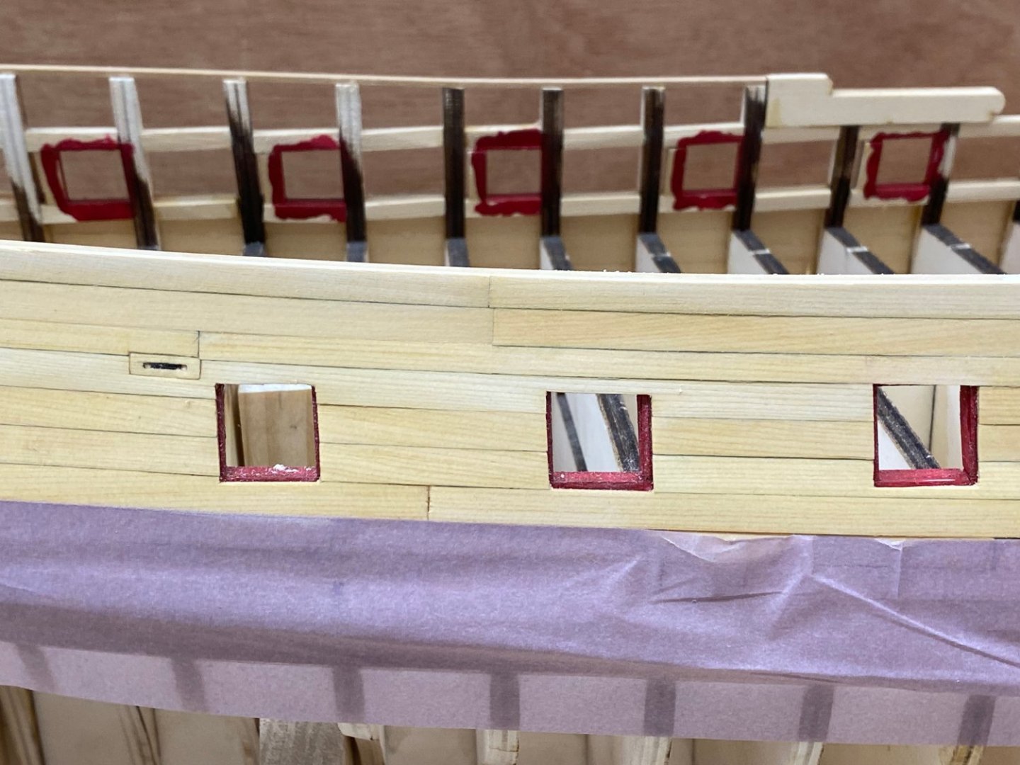
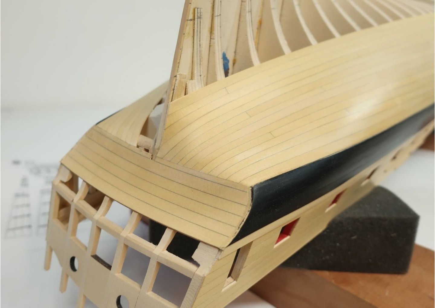
Starboard side planking above the wales is complete. Not without "issues" however. As is probably apparent in the pictures below I was not very careful in picking planks that were all the same shade of "cedar". I have gone through the planks that I have for the port side and excluded those which are on the darker side. Hopefully the port side will look a little better in that regard. As for plank widths I used a 5/16" for the top, plank at the bow but by the time I got done "fairing" the bulwark tops I doubt more that an additional 1/32" was necessary. So "pretty close"? At the waist the 3/16" plank was a bit too tall and had to be sanded down a bit to match the top of the bulwarks. At the aft hance piece I had to use two pieces to cover it. Not sure what or where things got "off" but I do not know what, if anything I could or should do now. Hopefully the port side will come out closer to what is on the plans although that might cause over problems down the line. I did not get a really tight seam at the stem. It was difficult to get the planks to make the bend around the bow. I finally soaked a plank and bent it place to dry for the top 1/4" plank. Will do that for all the 1/4" planks on the port side and maybe get tighter seams. And my biggest error was getting two plank seams almost directly above each other - and at the very top of the quarterdeck area. Not sure what I was drinking when that happened but it is about where one of the channels will go so may not be all that noticeable. Now on to the port side.


- 389 replies
-
- 7
-

-
- winchelsea
- Syren Ship Model Company
- (and 1 more)
-
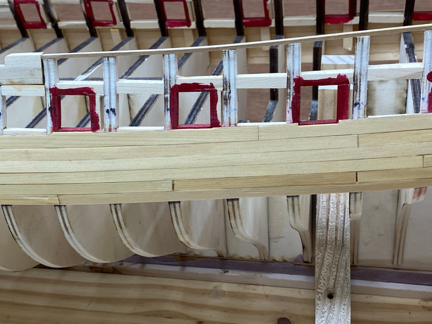
So - After tearing out the wales and replacing them I added the first strake of 1/4" wide planking. I had to use a 1/4" wide piece at the stern on the port side to get the fifth plank to come out even with the bottom of the qgallery door frame but... Adding the first row of 1/4" planking was a real "exercise" trying to judge when to use a 5/16" wide one to get the required gap and when to assume I can cut a 1/4" plank thin enough and still have it hold together. In any event I am proceeding to add the rest of the 1/4" wide planks. I am working on a set of measurements to try and understand where the top of the 1/4" planking should sit on the side so I can adjust the last plank to "hit the mark" and not mess up the upper rows. Here is the port side - the 1/4" plank at the stern is the third one from the bottom and I wiped the planks with paint thinner - it is not really that yellow.


- 389 replies
-
- 3
-
-
- winchelsea
- Syren Ship Model Company
- (and 1 more)
-
Speaking of the friezes; should they be printed by ink jet or laser printer? Any special paper weight or finish?
- 1,784 replies
-
- 1
-
-
- winchelsea
- Syren Ship Model Company
- (and 1 more)
-
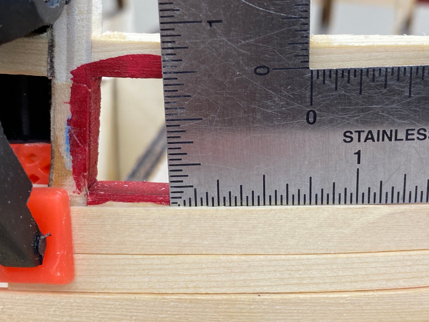
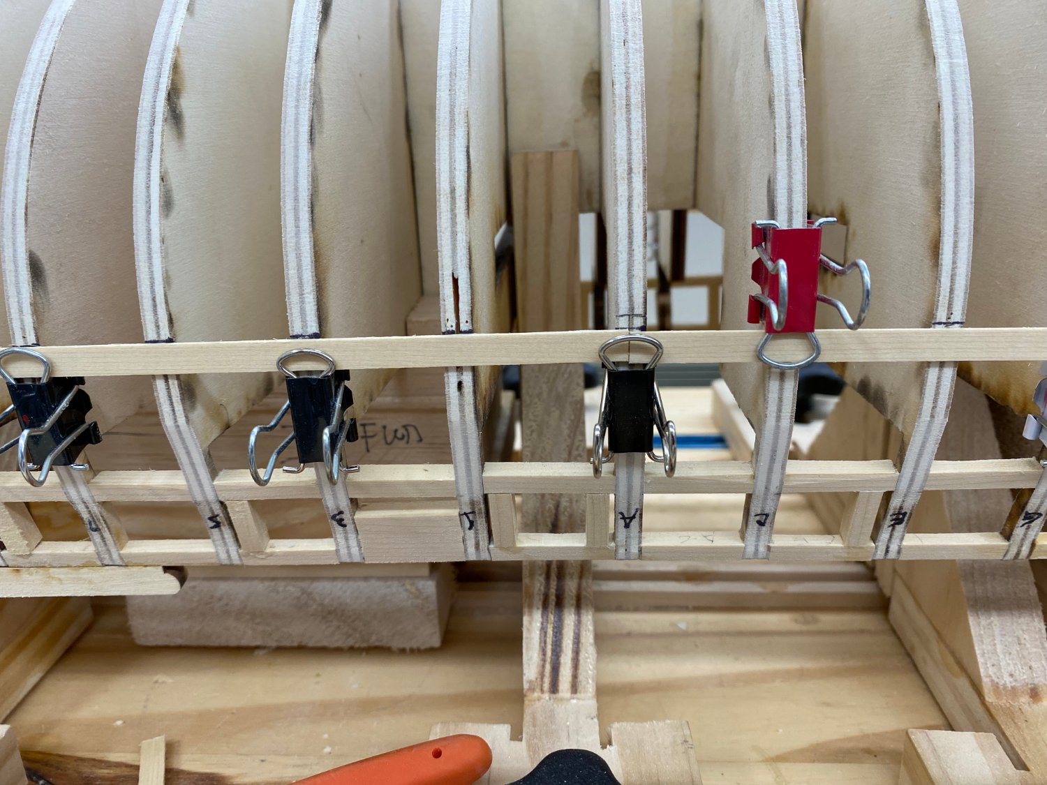
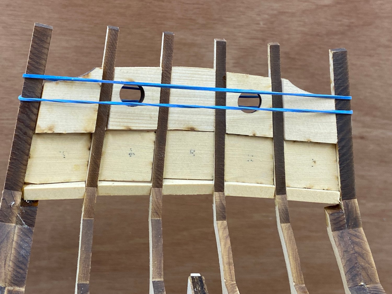
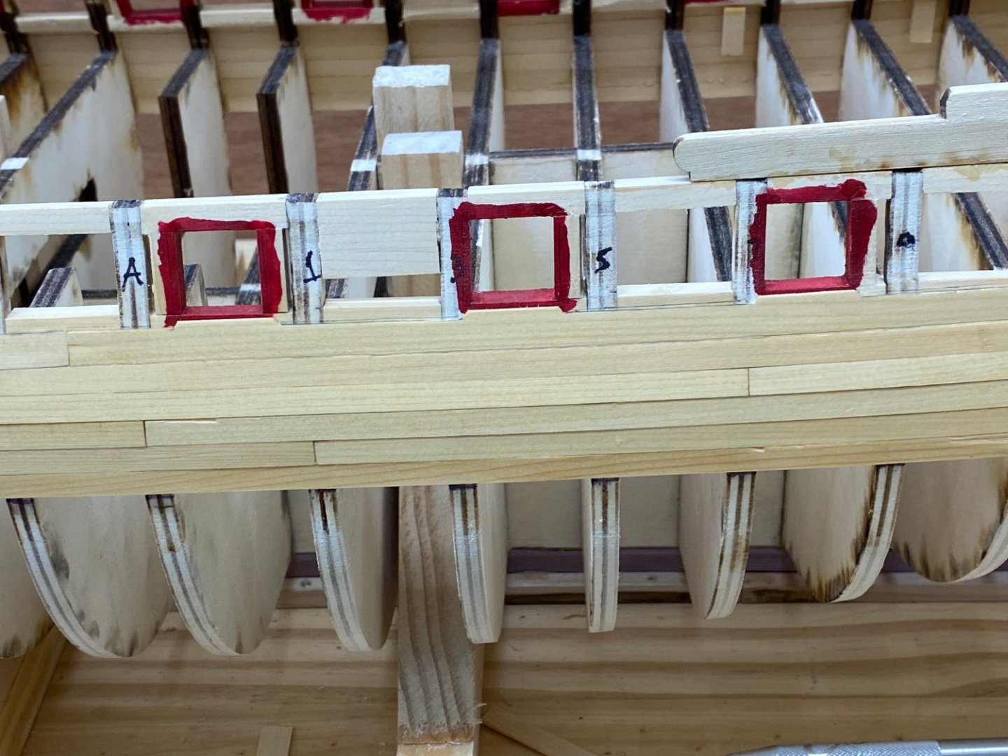
I got the bottom stake of the Wales replaced on both sides using the 1/4" planks ripped to 7/32". Luckily I had marked the bulkheads for the "Wales Line" with a Thin Sharpie so the sanding necessary to get the last shards of the previous planks off did not destroy the marks. With the bottom stake in place I added the next four strakes at the bow (only the first two are glued in) to see what the situation is with respect to the gun ports with the first 1/4" plank added atop the Wales planks. Clearly the plank will have to be cut down to accommodate gun port 1 as the plans show. Gun port 3 is certainly closer than previously but since the plans show the plank running along just at the bottom of the port opening (including the port stop). This time it looks like I am about 1/32" high as the 1/4" strake is just at the top of the lower sill. I would have to put a 1/32" notch in it for the port stop. Gun port 5 (third one back, starboard side) shows about a 5/64s (ruler is marked in 32nds) gap between the top of the first 1/4" plank and the top of the bottom port sill. The plans show a gap of about the same distance. This certainly better than what I had before and is "close enough" that am going to proceed and add the rest of the Wales timbers.


- 389 replies
-
- 2
-
-
- winchelsea
- Syren Ship Model Company
- (and 1 more)
-
Back to where we started. Given the likely consequences (Thanks Glenn) of proceeding with the Wales too high by 1/8" or so I removed the offending planks. It was easier than I would have thought. All the planks were edge glued with Weldbond (my preferred glue) and to the bulkhead with medium CA. I applied the CA debonder at the top of each bulkhead and applied a rag soaked in isopropyl alcohol to the planks along their length. Sometimes an entire plank would come off, others times just pieces. Most of the bulkheads had small remnants of the plank still attached. I soaked these with debonder and then used 120 grit sandpaper to remove them. More 3/64 X 7/32" planks are on the way but I ripped some of the 1/4" planks down to 7/32" so I can proceed with the Wales now.

- 389 replies
-
- 1
-
-
- winchelsea
- Syren Ship Model Company
- (and 1 more)
-
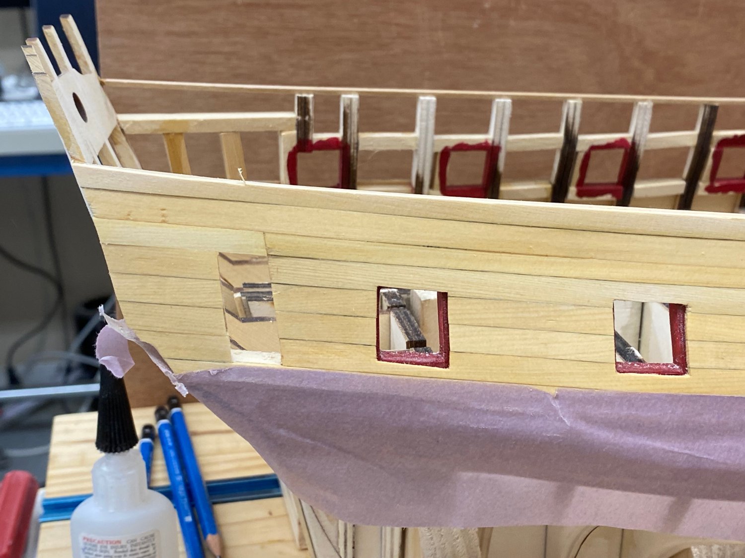
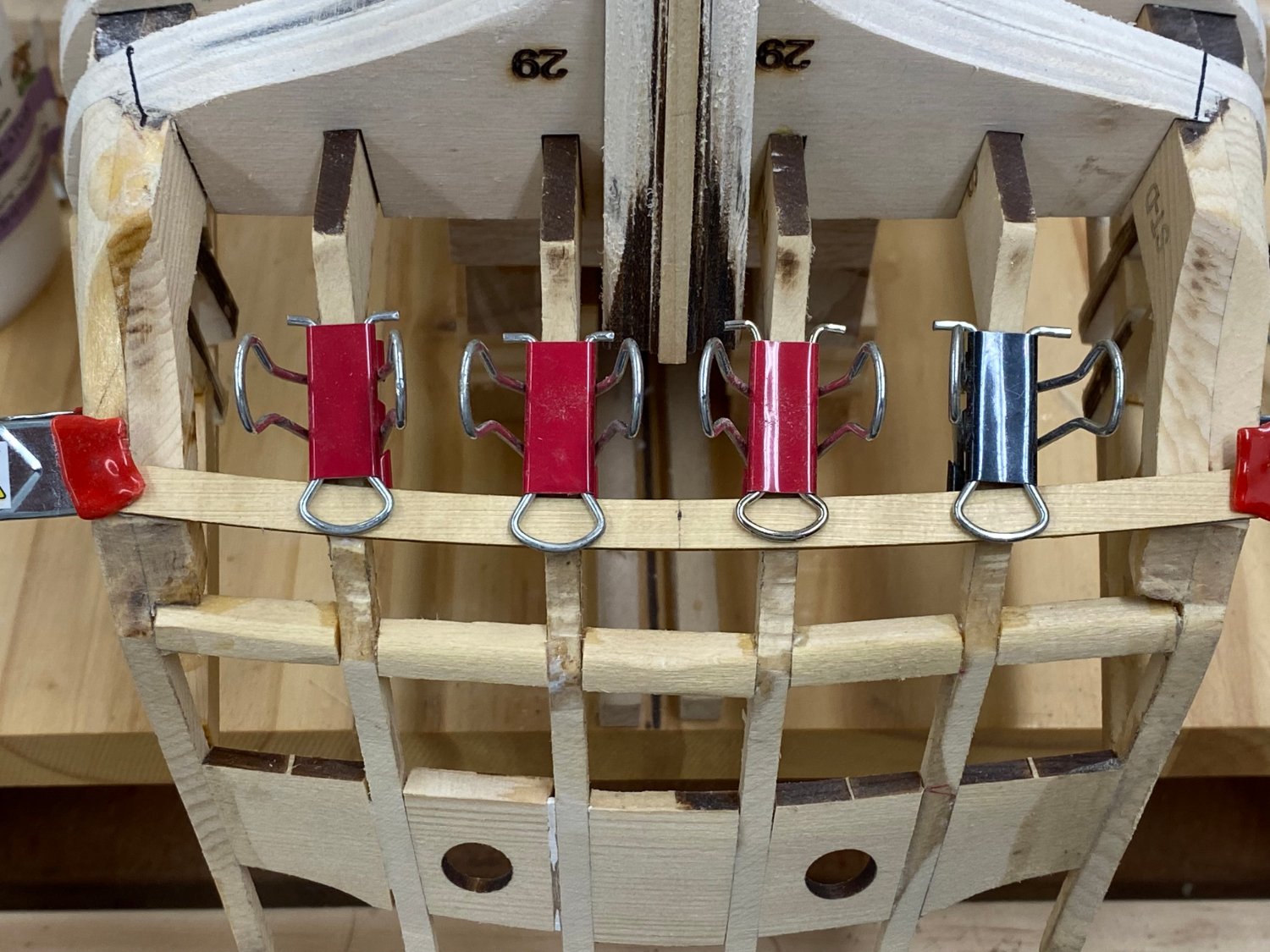
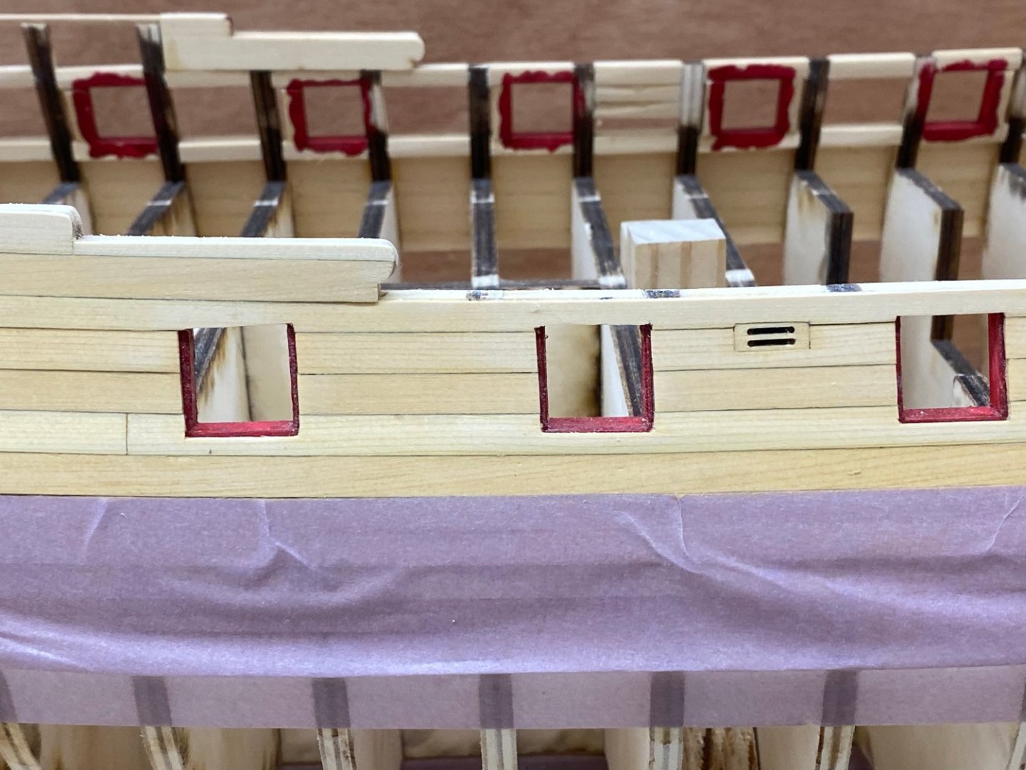
Having gotten the forward part of the first row above the wales in place I decided to work my way up between the bow and the first gun port, at least until I get to the top of the gun port. The first row was no problem but despite soaking the piece in water and bending it in place I could not get the next piece to "follow the curve" around the bow. It wants to take the shorter path which would run inside of the upper sill and lead to all kinds of problems with the next row. So I put an additional piece between the sills between gun port 1 and the bow. Hopefully this all gets covered with interior planks.

- 389 replies
-
- 1
-
-
- winchelsea
- Syren Ship Model Company
- (and 1 more)
-
I used 7/32" (or what I bought as 7/32") which turned out to be between 11/64 and 1/4.
- 389 replies
-
- 1
-
-
- winchelsea
- Syren Ship Model Company
- (and 1 more)
-
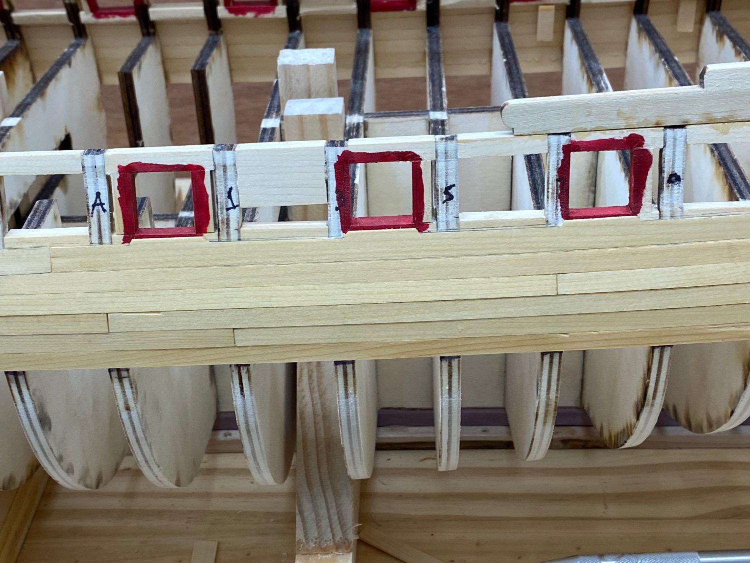
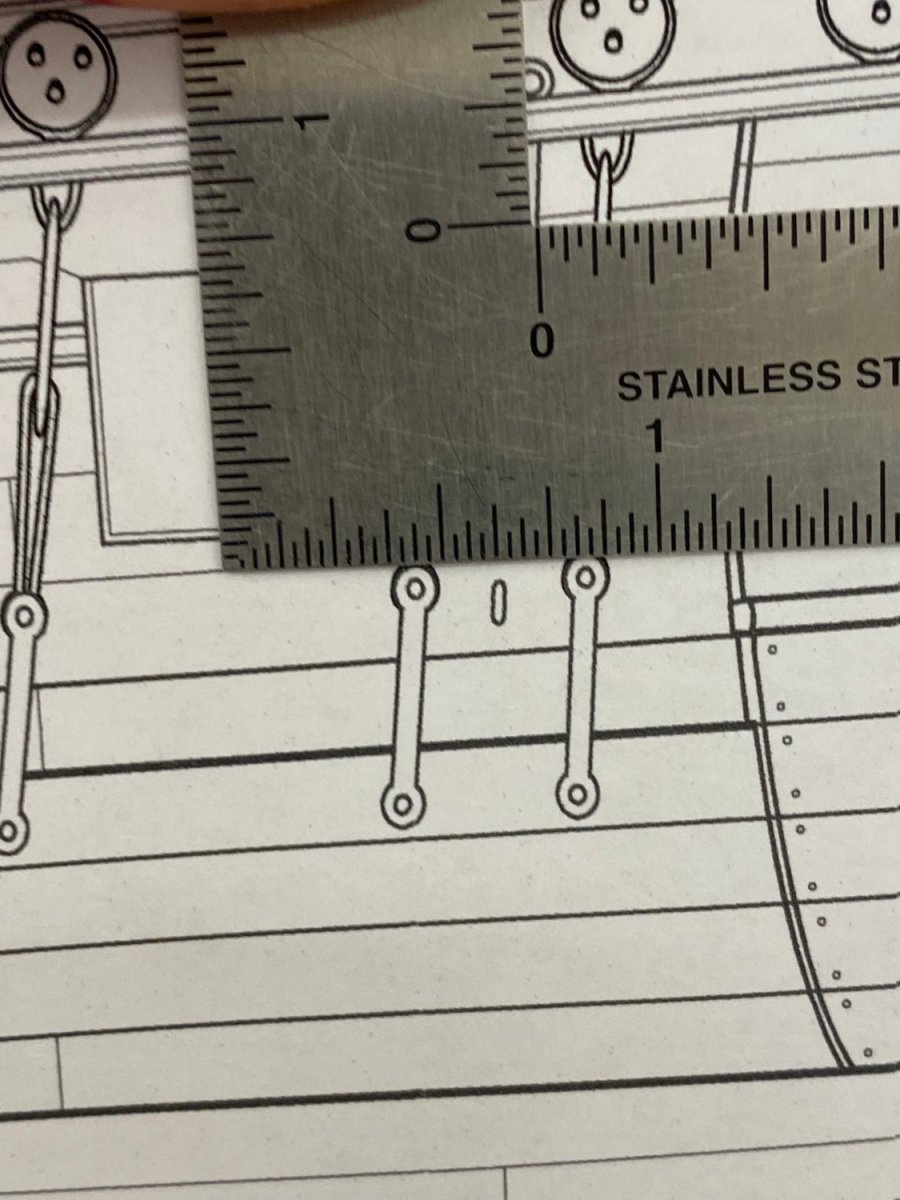
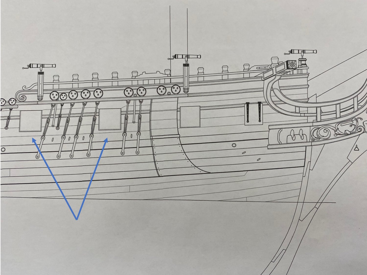
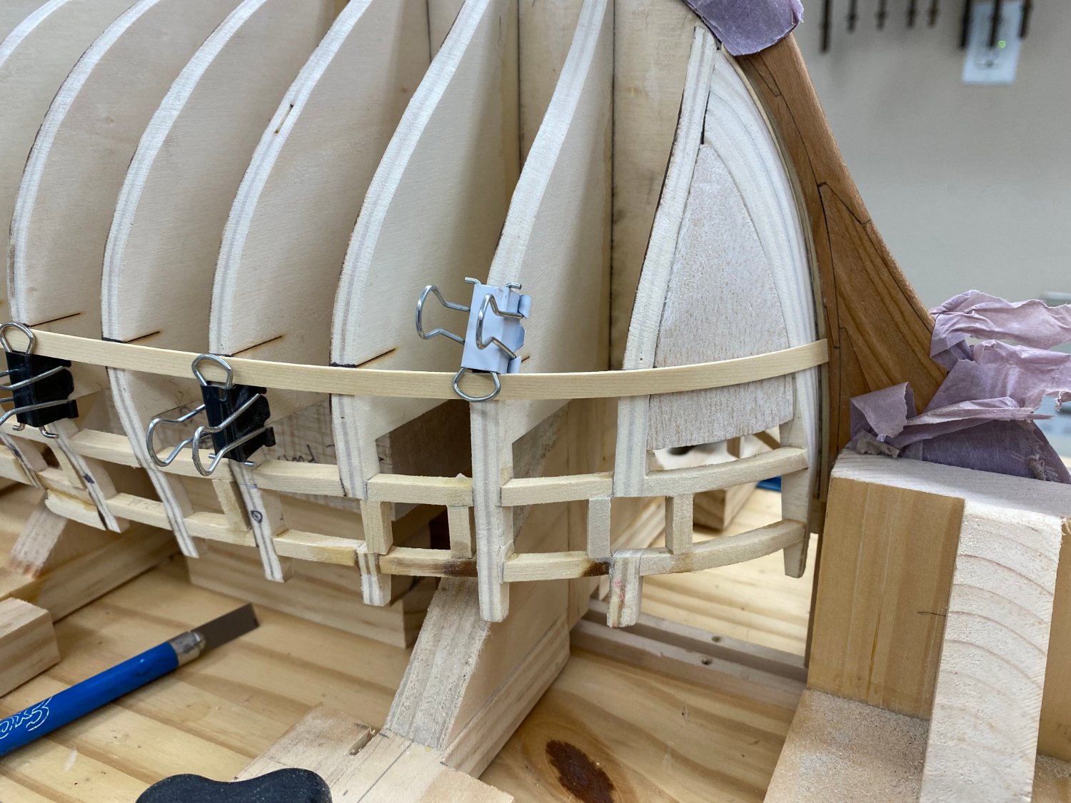
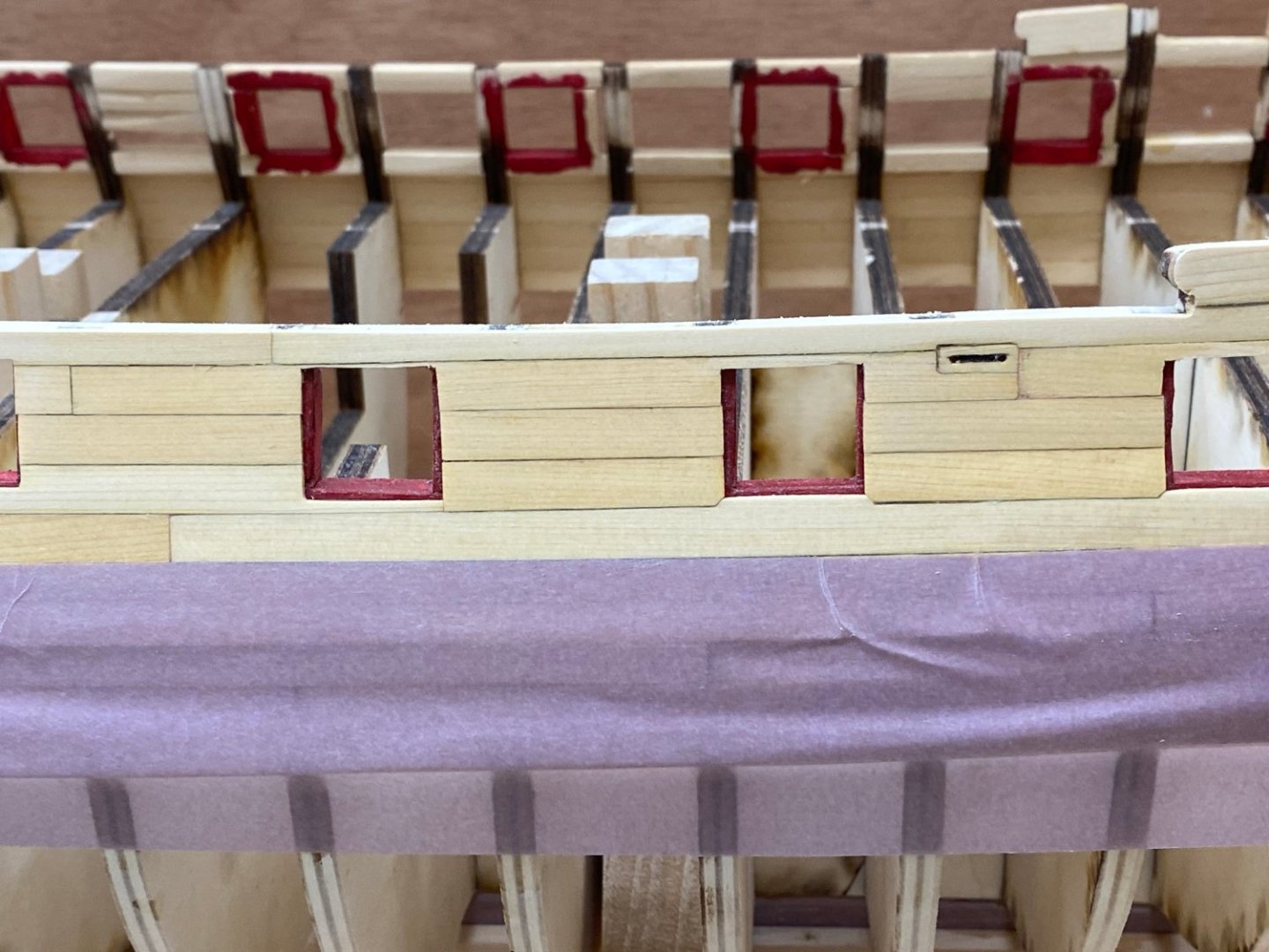
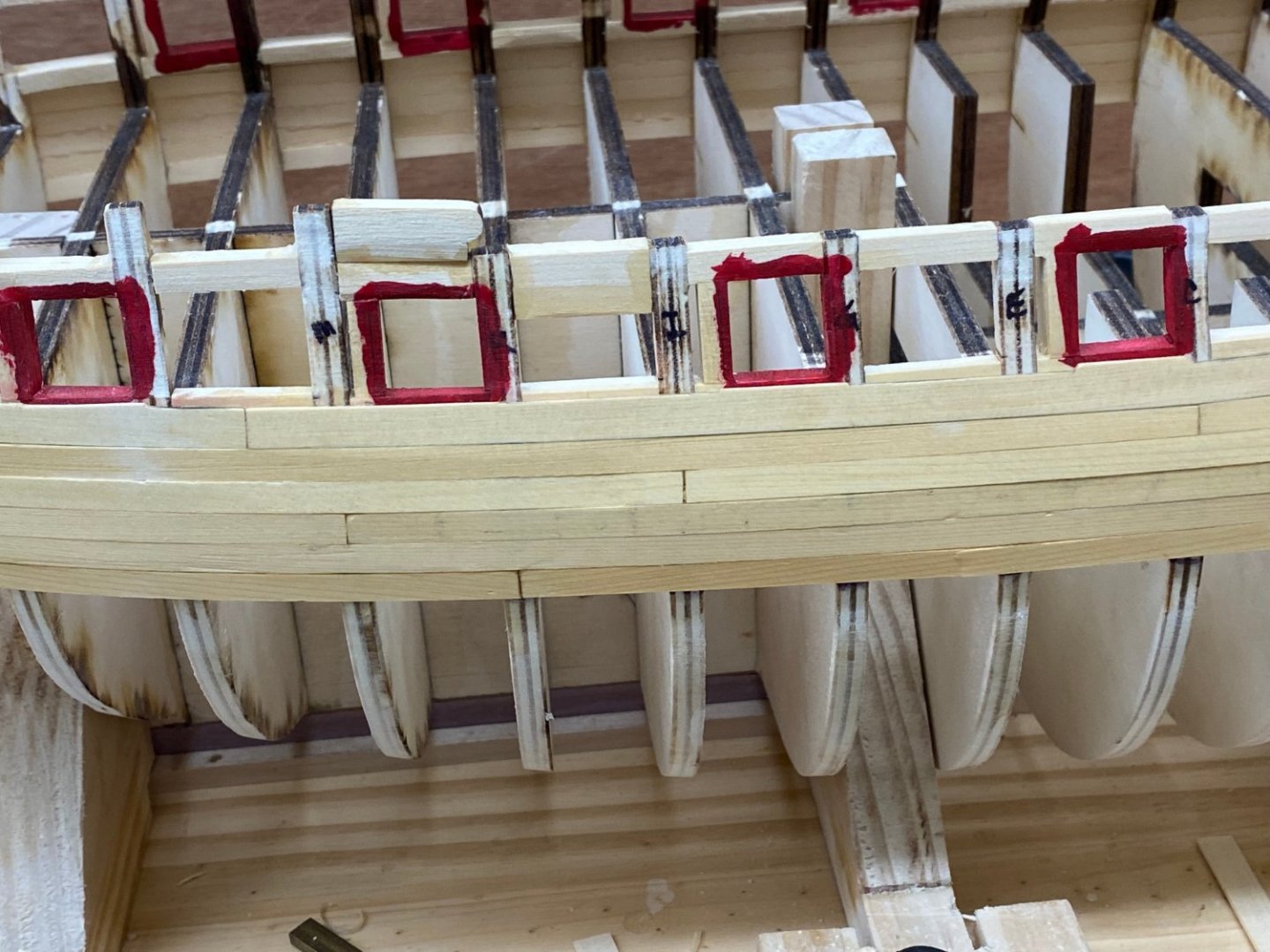
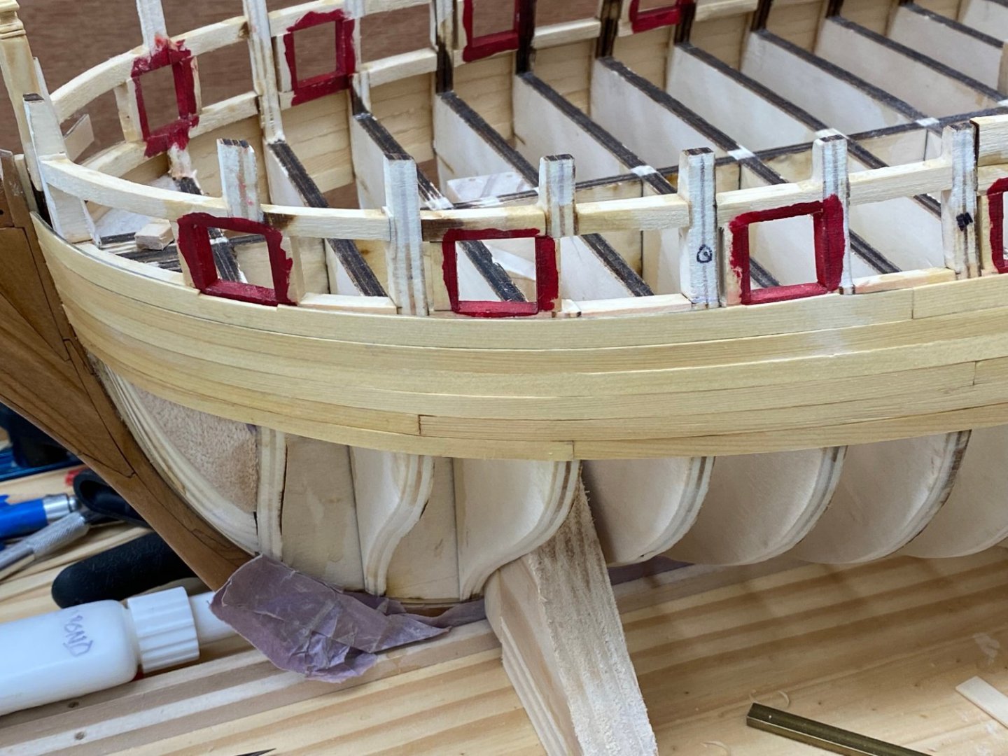
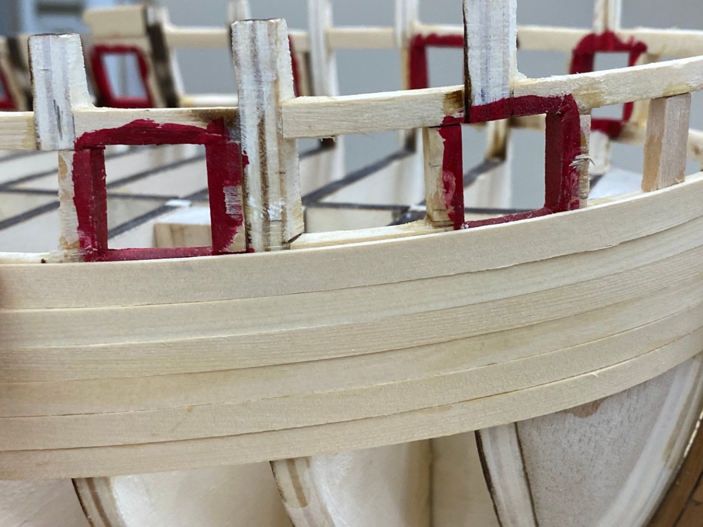
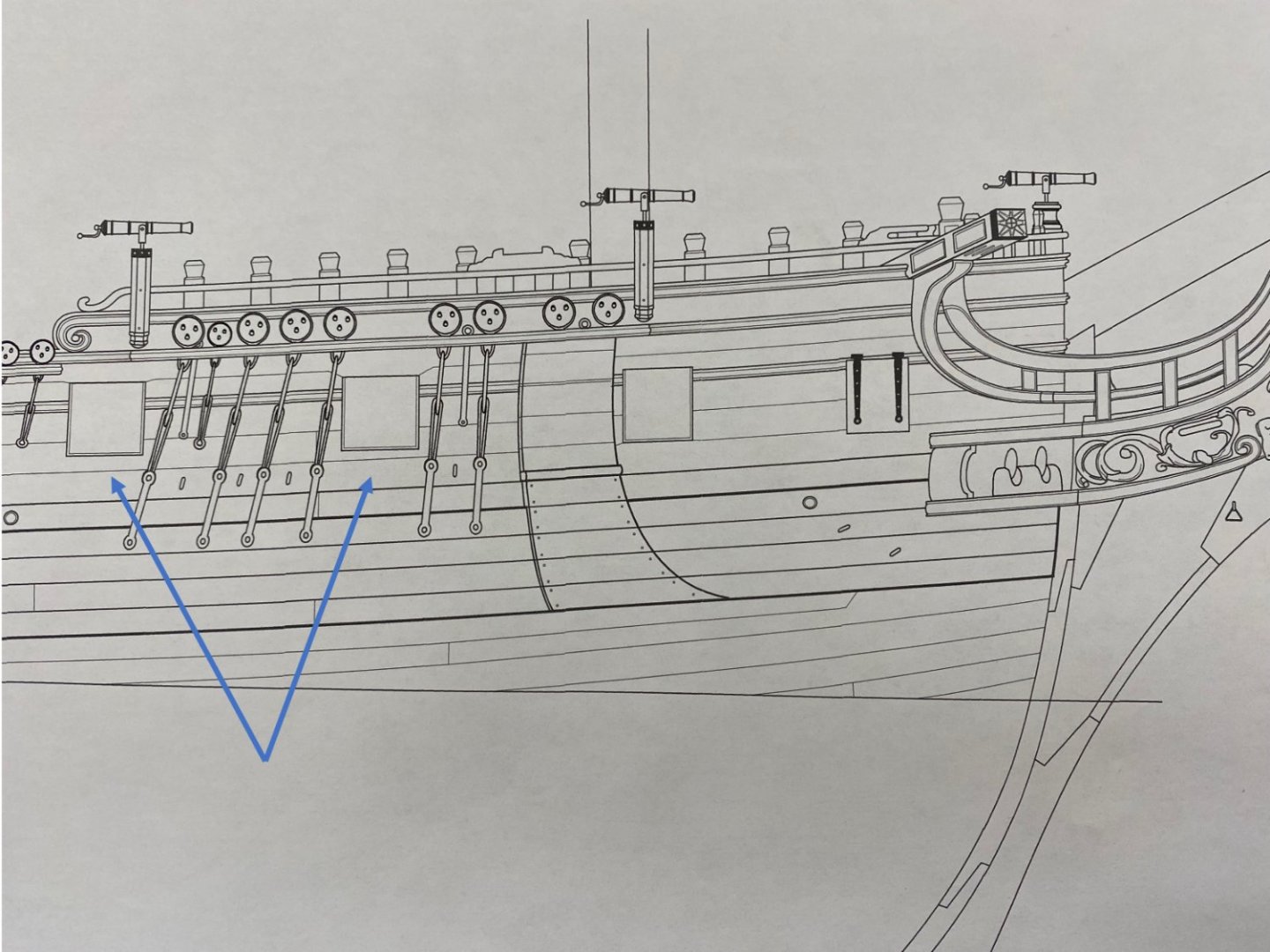
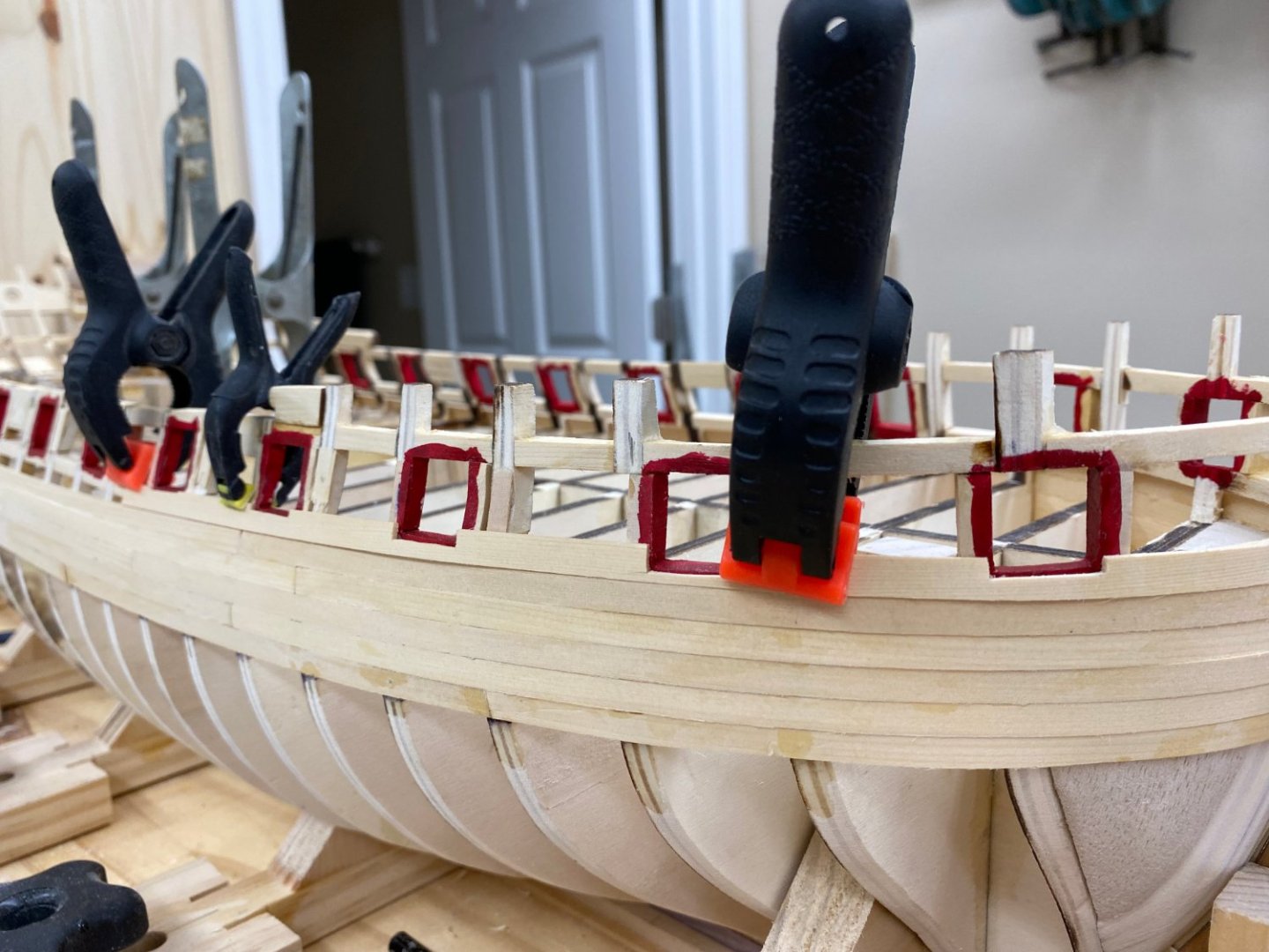
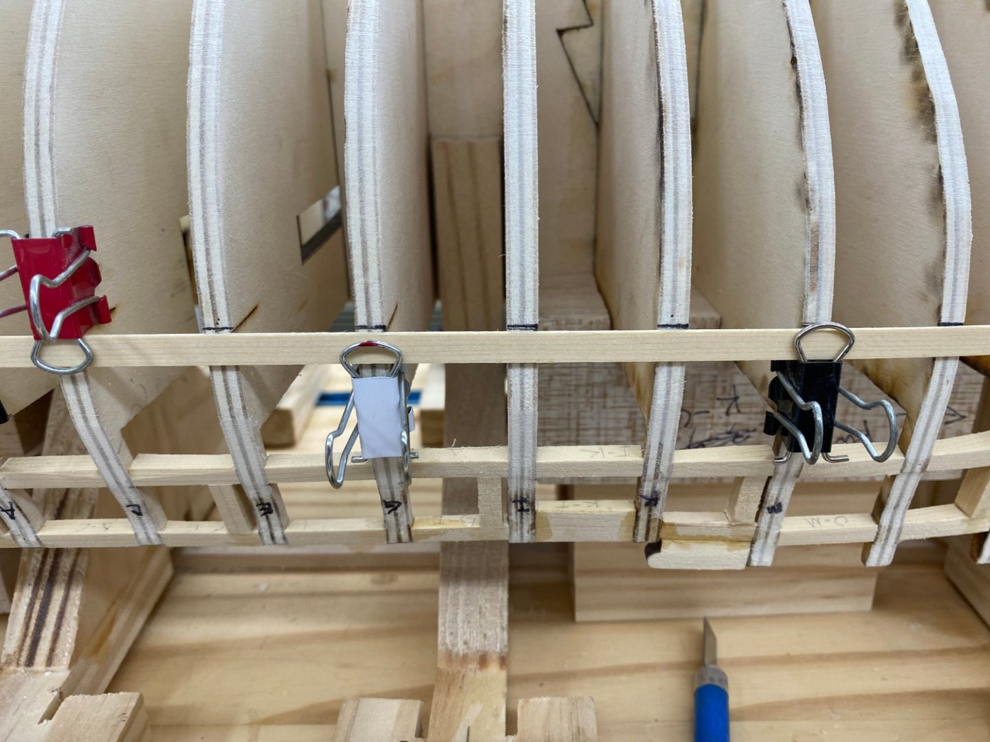
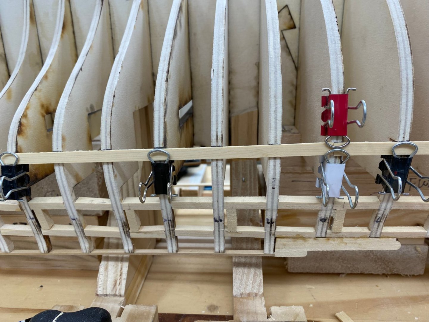
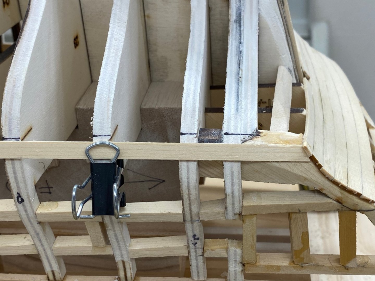
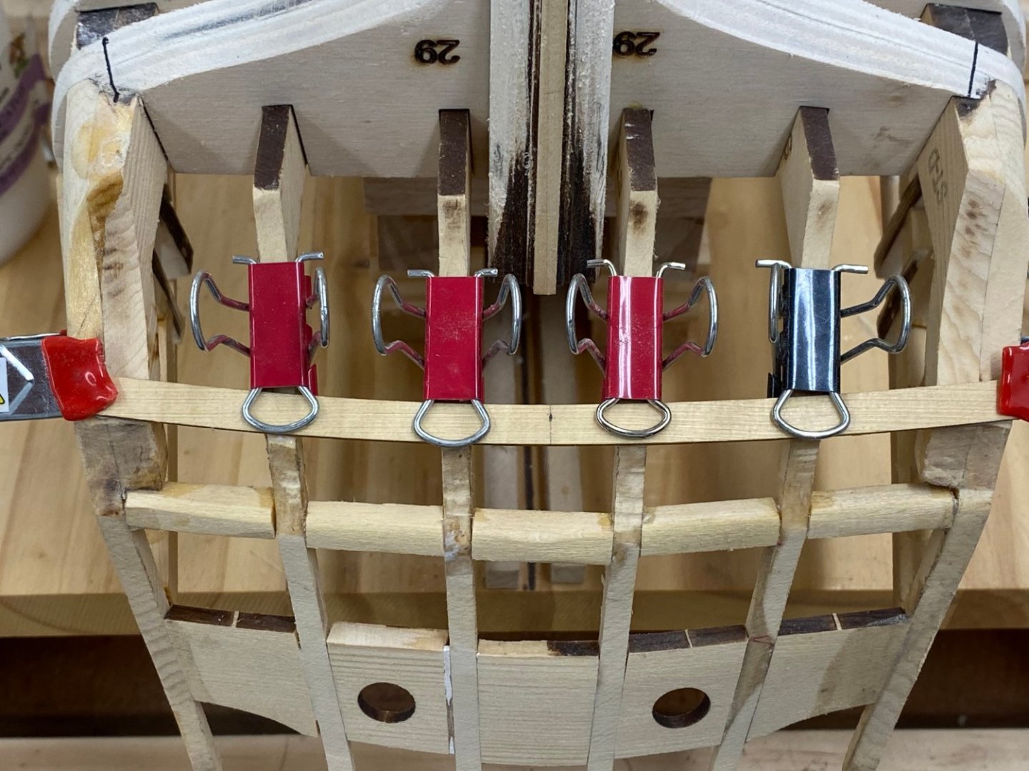
Thanks Glenn - I will at least see how things go the "preferred" way. But, no matter how the port stops are created you have to start adding the planks above the Wales - which is where the first "new issue" arises. According to the plans the first plank above the Wales at the bow would impact the first two gun ports, aft of bulkhead Q that plank would pass below the gun port and thus not need any additional "attention". On my model the first strake above the Black Strake at the bow impacts every gun port as far back as Bulkhead G; five in all. So, obviously my Wales are either wider than those in the plan or are positioned further up the hull. (Clamps are holding the plank in place.) It appears that this problem was caused by my using planks that although sold as 7/32" wide were in fact considerably wider. I was very careful about plank thickness, I ran them all through the thickness sander to get them all the same thickness (within the limitations of the thickness sander) but I never bothered to check the width. I checked the "stubs" from the Wales planking and they are all in the range of 0.238" to 0.245" (7/32 = 0.2188) so at least 0.020" wider than called for in the plans. After five planks averaging 0.240" instead of 0.22" makes the combined Wales about a tenth of an inch "taller" than the plans indicate. By my measurement the plans show the first strake above the Wales passing 2mm (.08") below gun port 3 (third one back on starboard side). My plank is about 4mm (.16") higher than shown on the plans. So at least most of this is caused by the plank thickness issue. The rest could easily be caused by differences in locations of the first wales strake and/or the location of the lower sills. In any event I am where I am and will continue the planking. I am sure this is going to cause a problem at some point I just have no idea what or when.
- 389 replies
-
- 1
-
-
- winchelsea
- Syren Ship Model Company
- (and 1 more)
-
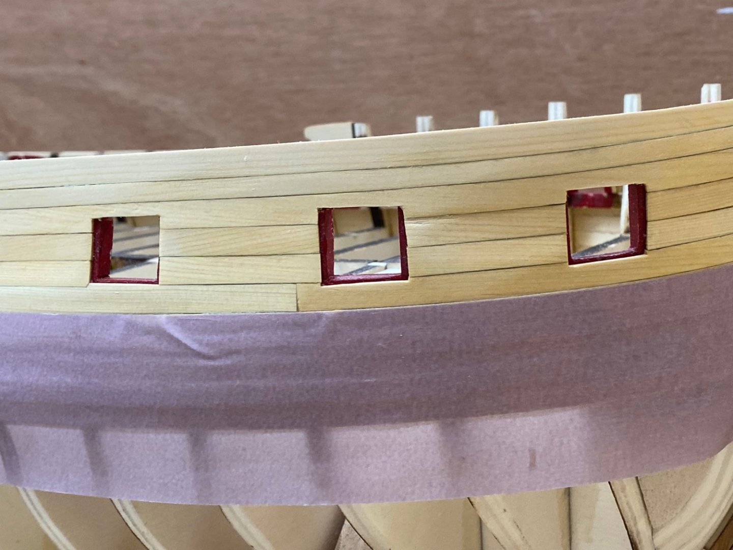
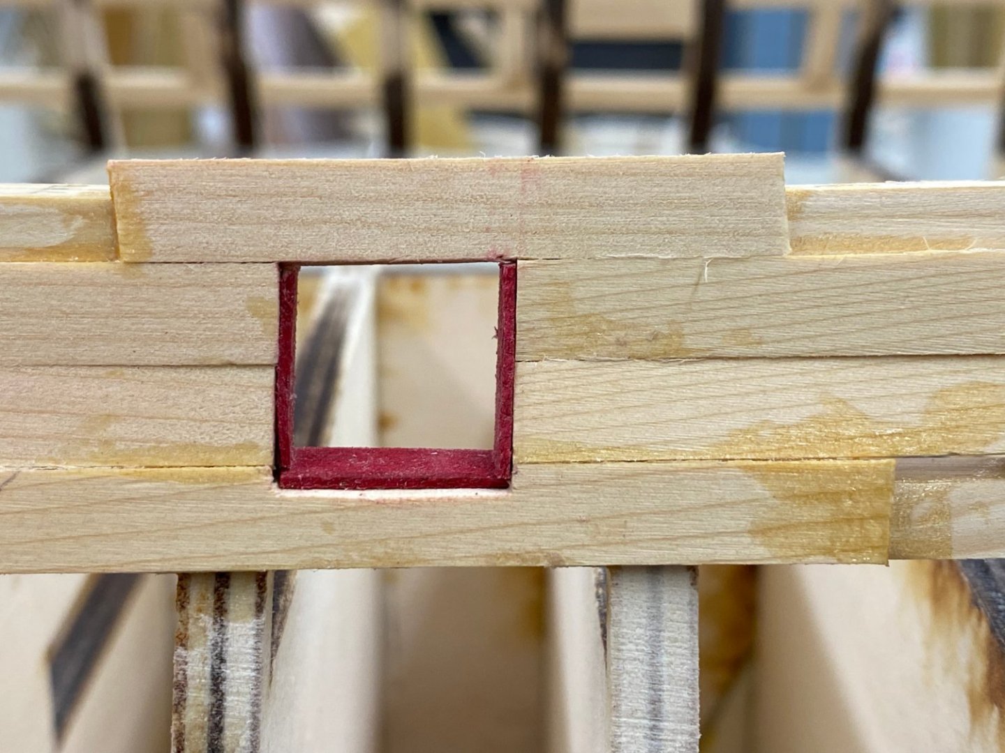
I have competed the five rows of 7/32" planks that make up the Wales and the black strake. On to the "above the Wales" planking which are mostly 1/4" wide. I was thinking about the 1/32" port stop that is supposed to be left around the sides and bottom of each gun port. I am considering rather than try and plank to that accuracy it might be easier (for me) to plank all the way to the edge/bottom of the gun port (where overages can be corrected fairly easily with a sanding stick) and after all the above wales planks are done to add a 1/32" thick strip around the inside of the gun port, inboard of the planking so, from the outside it appears as if the planking stops 1/32" short of the gun port opening. This 1/32" piece would be painted red and be as deep as the gun port "sill" (which was 1/4" but has or will be reduced to something less as the inboard bulwarks are thinned down). I realize that this will make the gun ports 1/16" narrower than shown on the plans but I do not think it will be noticeable or impact anything else. PLEASE CORRECT ME IF YOU THINK/KNOW OTHERWISE! I used the previous version of my Winnie build (the one that has the dimension "discrepancy" at the stern) to prototype this. The material I used for the "lining" was 1/32" X 1/4" basswood. For the "real" Winnie I think I will use something that takes paint better, or at least does not swell and bend like the basswood did- boxwood probably). I need to decide in the next little bit as the first row of 1/4" planks is going to "hit" several of the gun ports.
- 389 replies
-
- 1
-
-
- winchelsea
- Syren Ship Model Company
- (and 1 more)
-
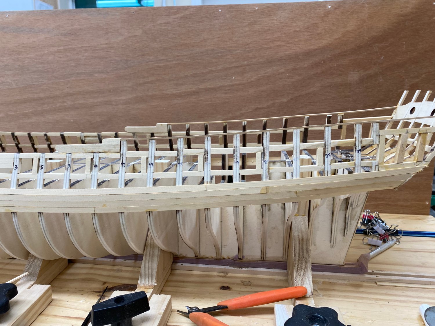
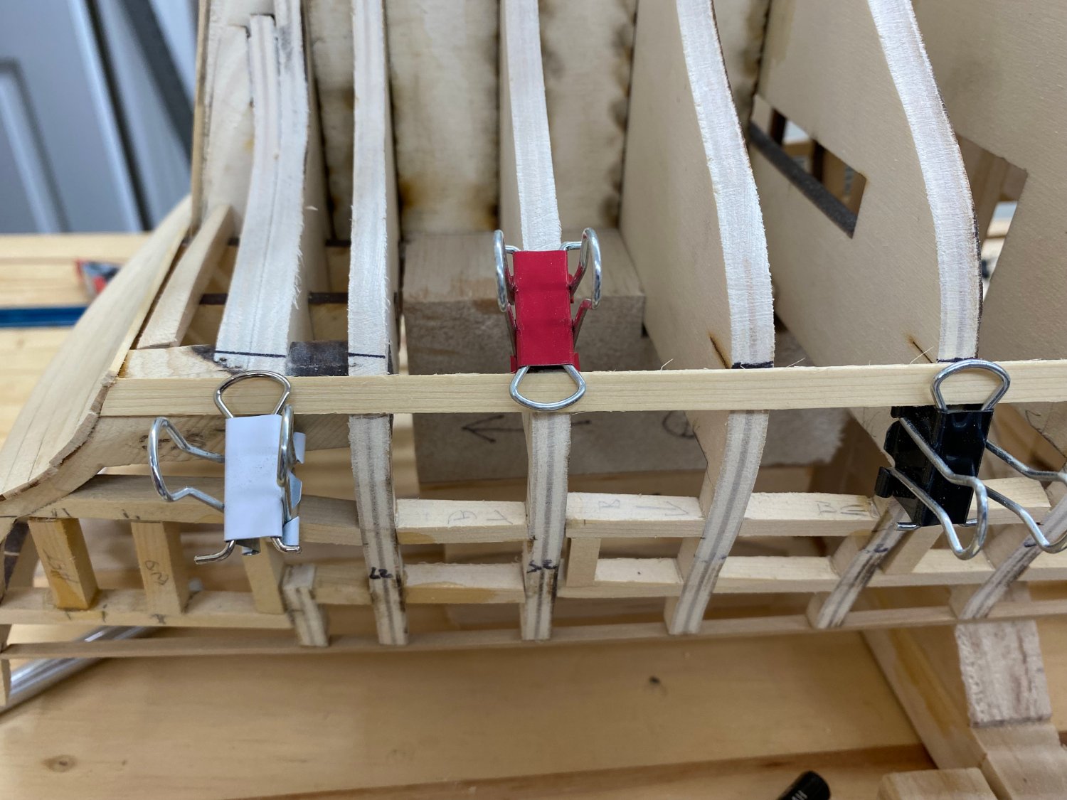
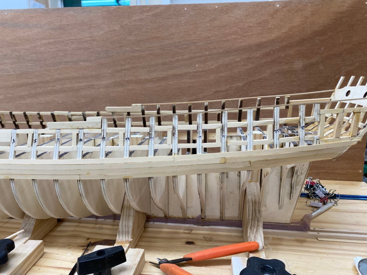
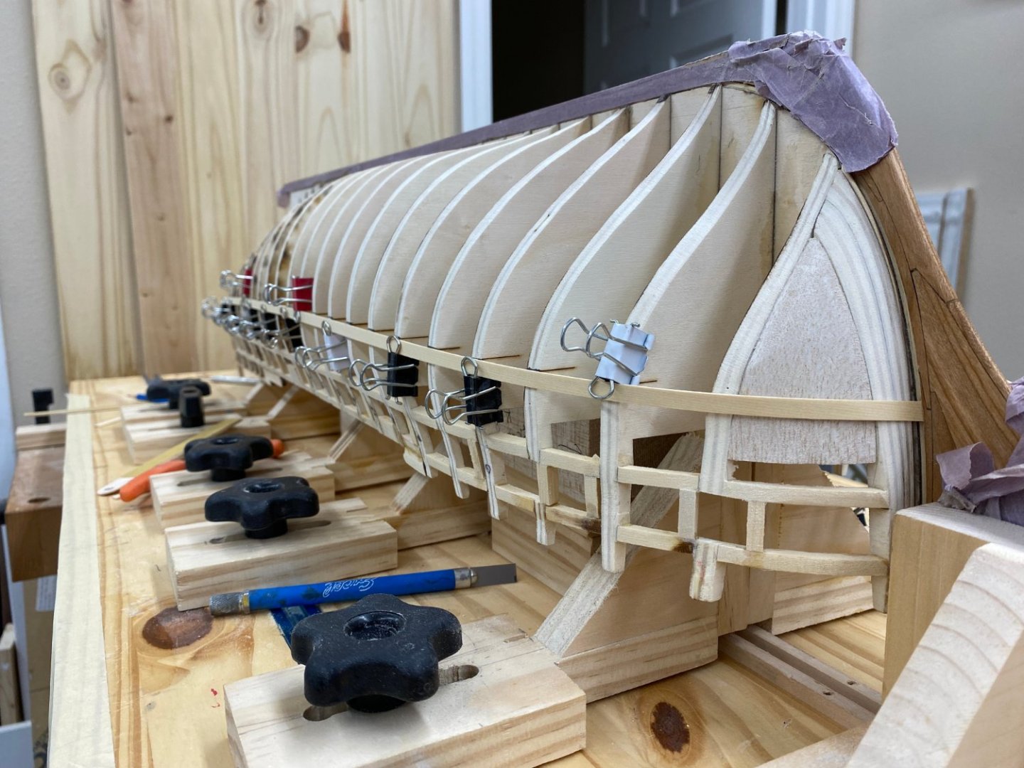
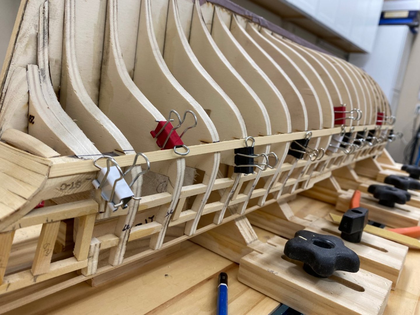
Now that I have the hull upright again I installed the bollard timbers that I finished while the hull was inverted. I will need them as I start to plank above the Wales. Speaking of which, I have four rows of Wales planking complete on both sides. I only have pictures of the starboard side at the moment. I did not worry about plank lengths or joint spacing as all four of these rows will be covered by another layer. I will use the plank length shown on the drawings for the black strake (practice). Here is the starboard side with four rows planked.

- 389 replies
-
- 2
-
-
- winchelsea
- Syren Ship Model Company
- (and 1 more)
-
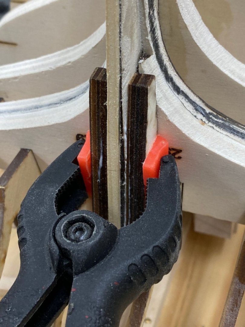
After a good deal of "messing around" I finally think I have the bottom strake of the wales in place (clamped) on the starboard side. Now on to the port side.


- 389 replies
-
- 5
-
-
- winchelsea
- Syren Ship Model Company
- (and 1 more)
-
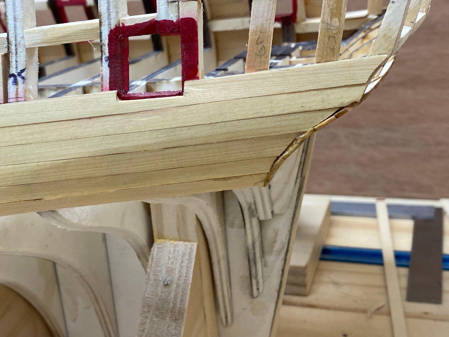
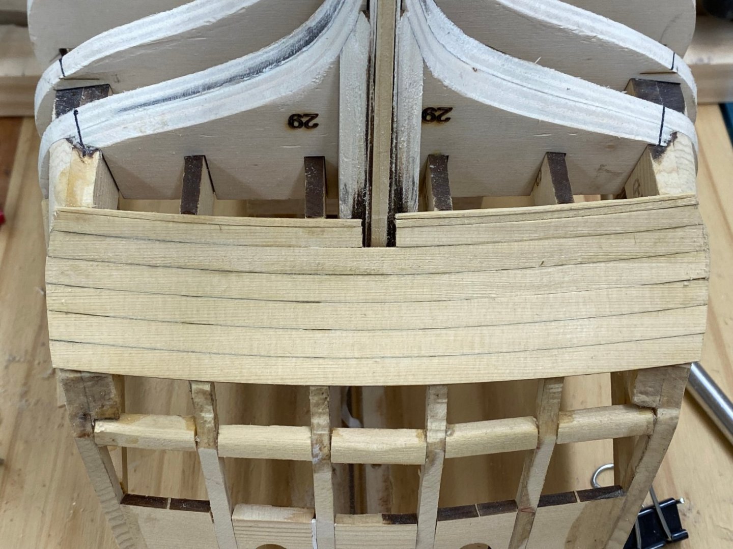
Having looked at the plans (again and again) as well as several other build logs I have decided to salvage some material from the laser carrier the lower transom planks came on and "fill in" the area above where the current planking ends so that it covers the top (bottom) of the lower curved portion of the stern timbers. I used the pieces between the laser cut pieces since they are already the correct curvature (more or less). I used one piece on the starboard side and two on the port. As the instructions state this will all be covered by a frieze so the extra pieces will not "show".
- 389 replies
-
- 1
-
-
- winchelsea
- Syren Ship Model Company
- (and 1 more)
-
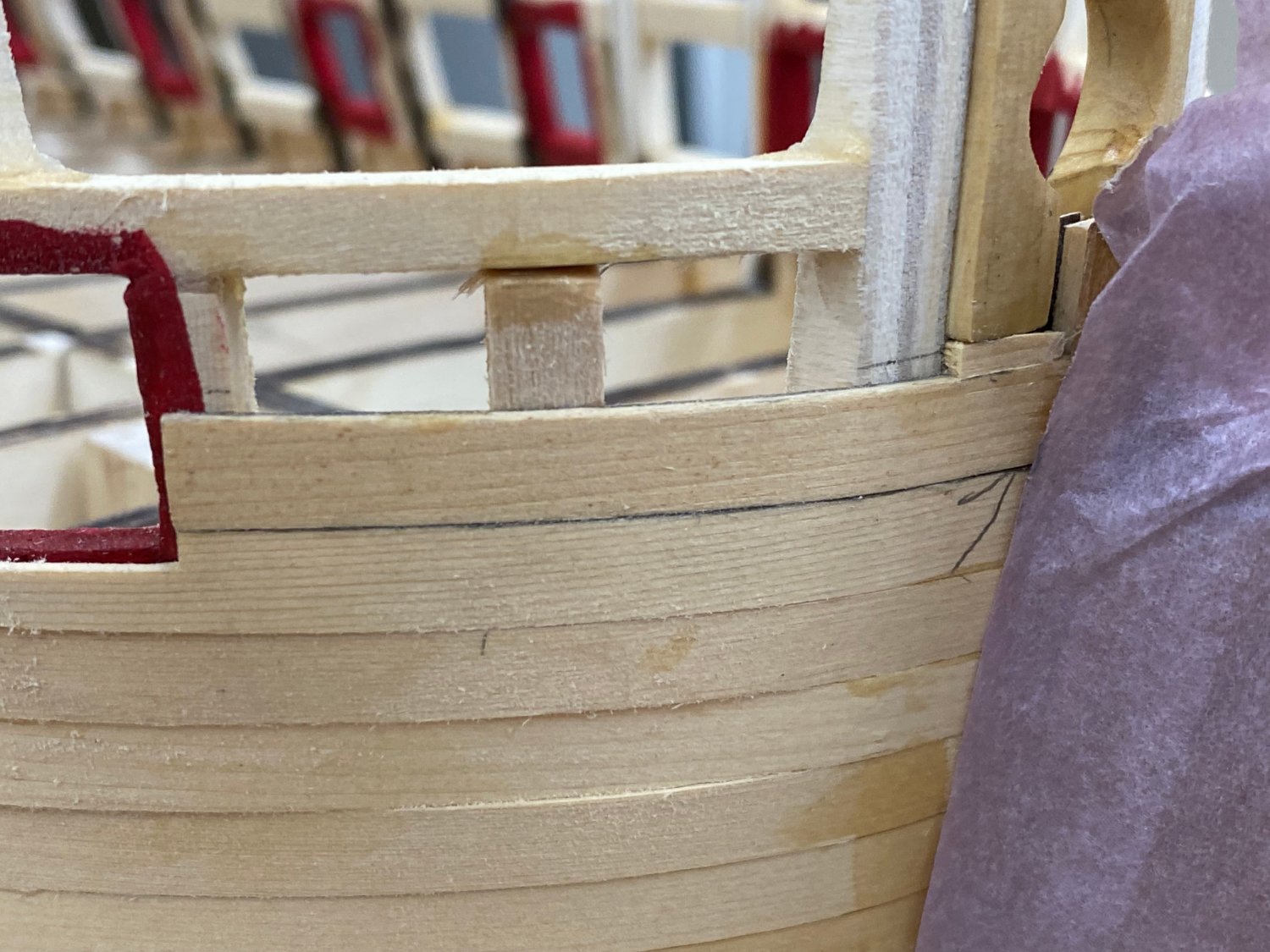
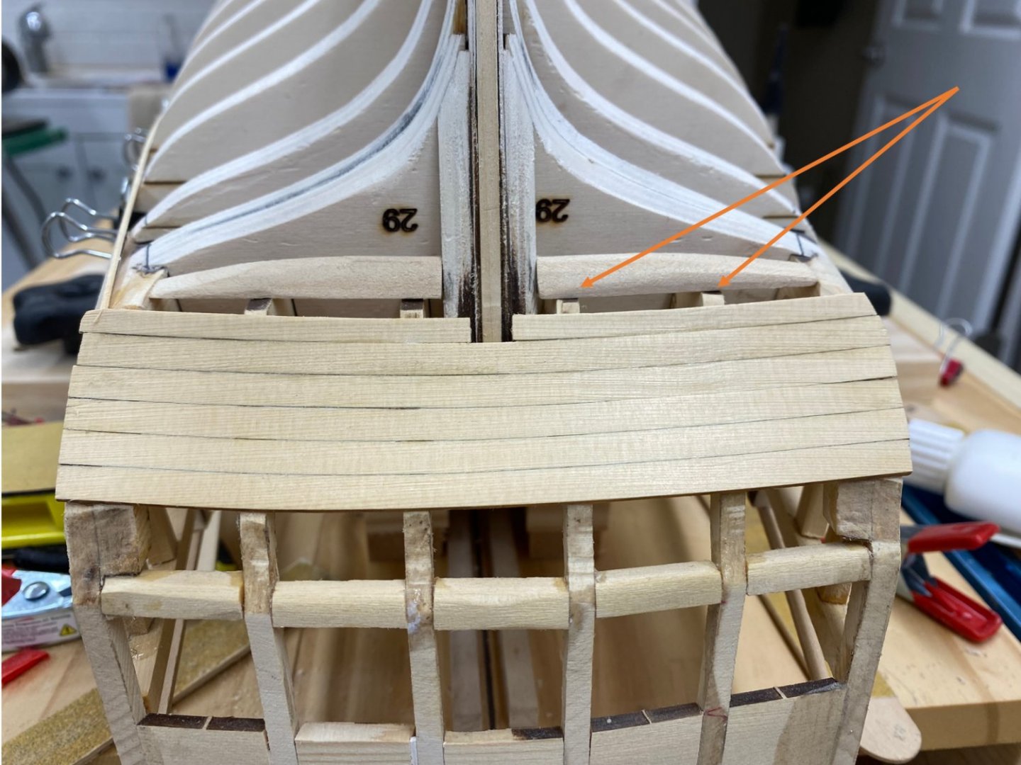
So I got the lower transom planking finished. It did not come out as even as I might have hoped. There is about an additional mm of the stern timber showing at the top (bottom) of the starboard side (see arrows) I am not sure what, if anything, short of ripping these out and trying again with another chapter 2 kit. I can see now that I started the port side a bit higher than the starboard which is probably where things went off the tracks. While I ponder that "issue" I have been trying to figure out where the bottom of the wales should hit the transom. This picture shows Chuck's prototype. This would seem to show the bottom of the wales intersecting at the bottom corner of the lower transom planking. If I do that on my model it looks like this: Which is pretty close to where the laser marks would place it. Is this correct?
- 389 replies
-
- 3
-
-
- winchelsea
- Syren Ship Model Company
- (and 1 more)
-
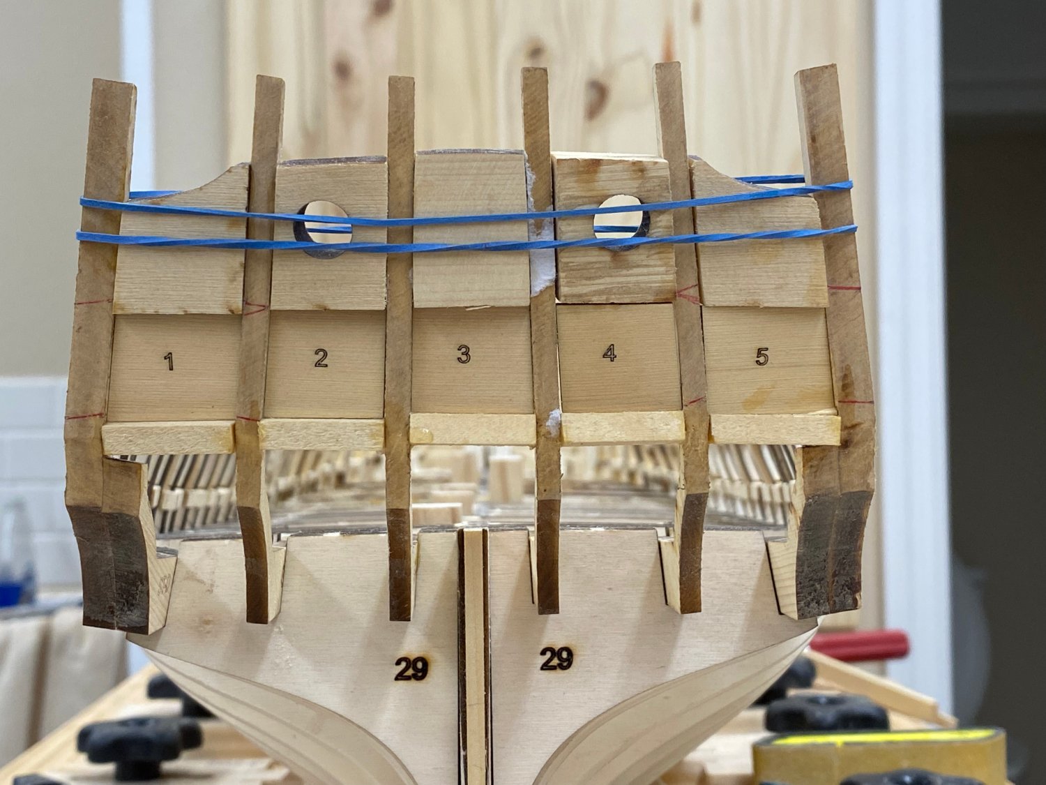
There is no turning back now! First plank of the lower counter is in place. All the rest depend on getting this one in the right place. I made a pencil mark in the center of the five whole planks - there is no local centerline reference but I use the stern rabbit to make sure I am not way off and now I can line up the other planks on #1.
- 389 replies
-
- 3
-
-
- winchelsea
- Syren Ship Model Company
- (and 1 more)
-
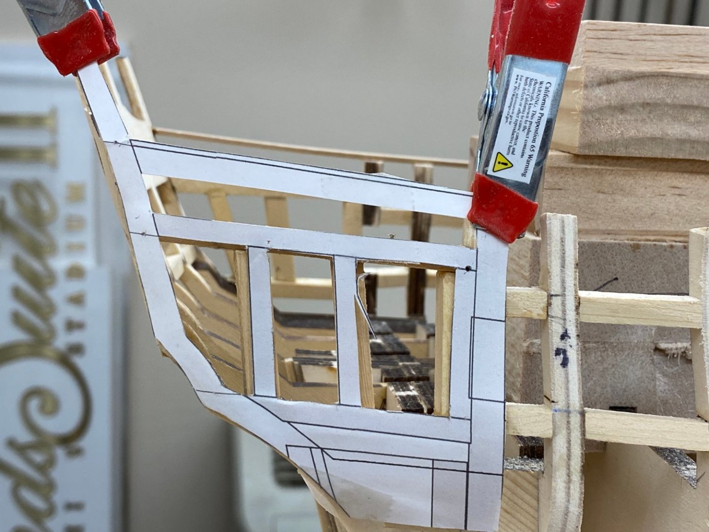
Many thanks Glenn - and yes you suggested this awhile back and I forgot it in my haste to "move things along". Somehow I managed to really mess up the starboard side, the port also but I only had to reposition the the "verticals" that define the door opening. The starboard side was a complete redo. Here is the redone starboard side with the plan.
- 389 replies
-
- 3
-
-
- winchelsea
- Syren Ship Model Company
- (and 1 more)
-
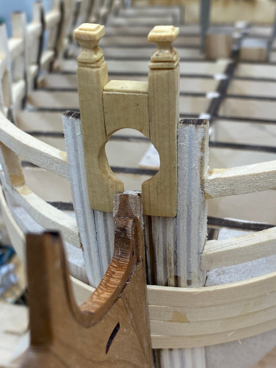
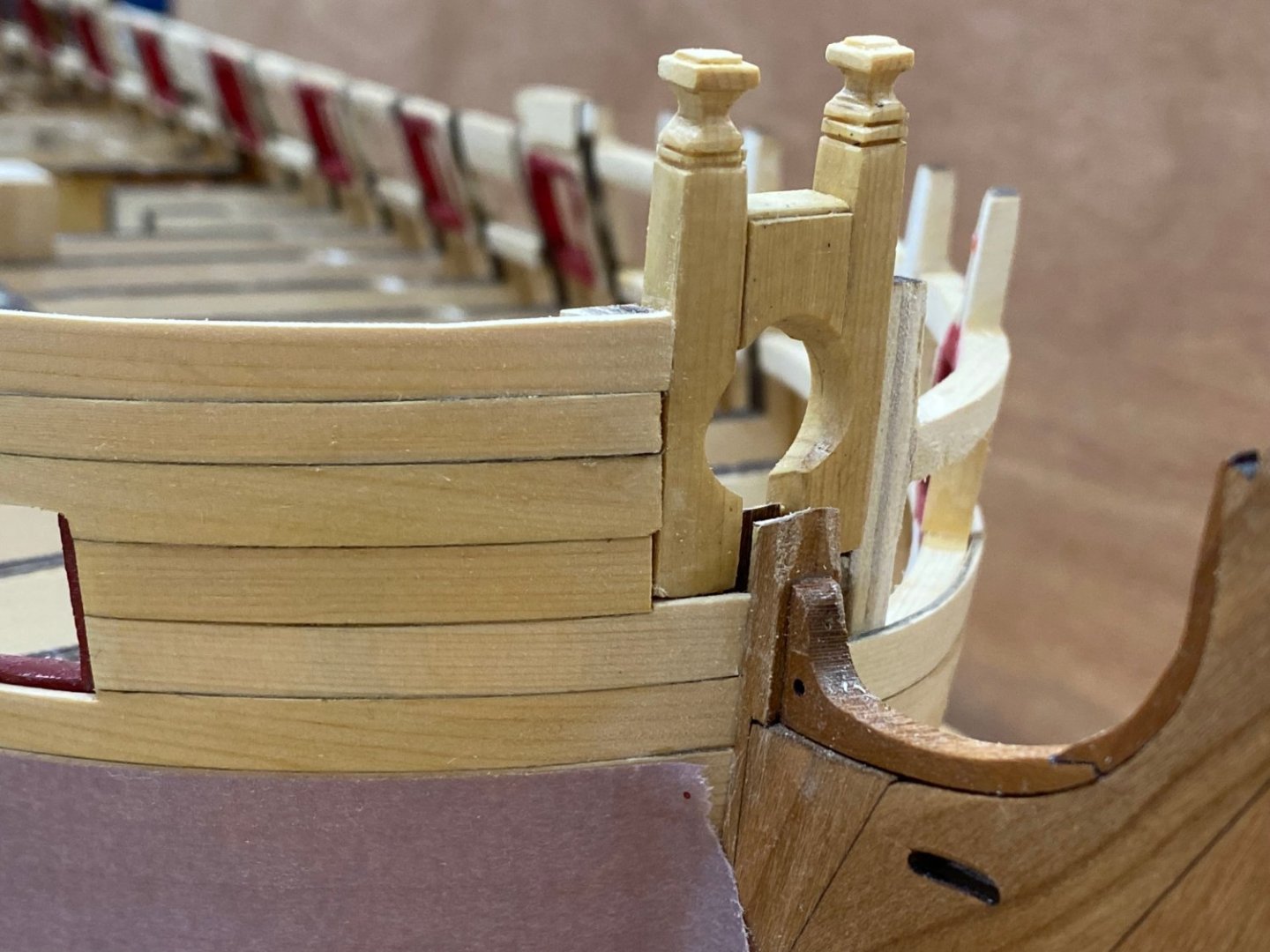
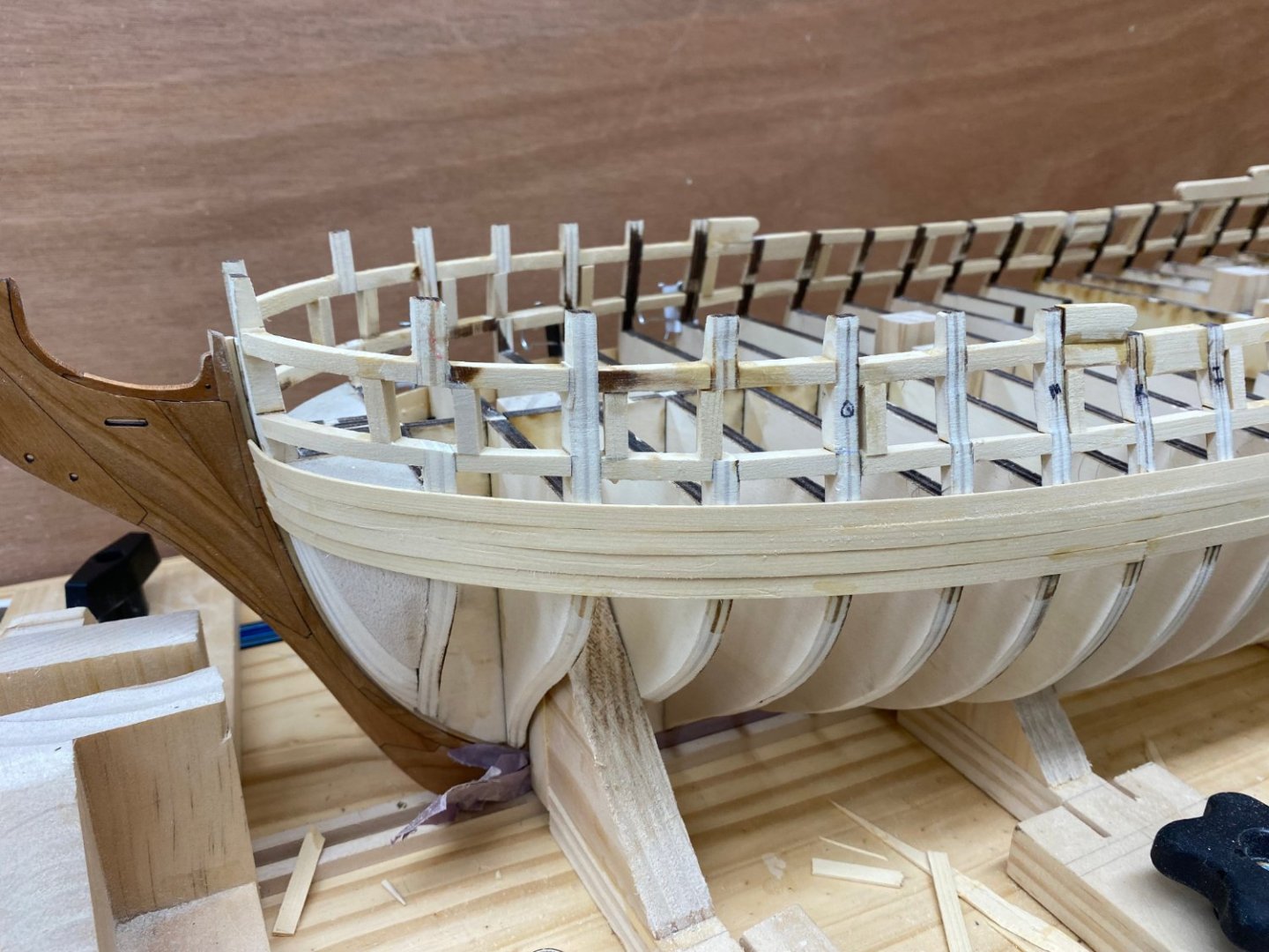
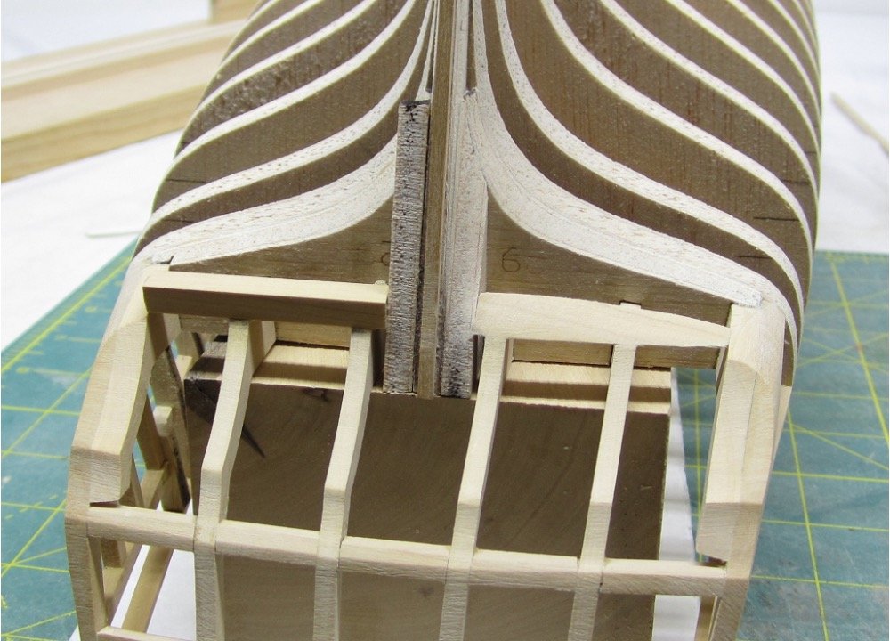
I fabbed the bollard timbers and dry fit them at the bow. They are drying after a coat of WoP. I got the qgallery framing completed and now all that remains is installing the bollard timbers and the hance pieces to complete the first chapter of the Winchelsea construction. Hull planking is not too far off now😀

- 389 replies
-
- 2
-
-
- winchelsea
- Syren Ship Model Company
- (and 1 more)
-
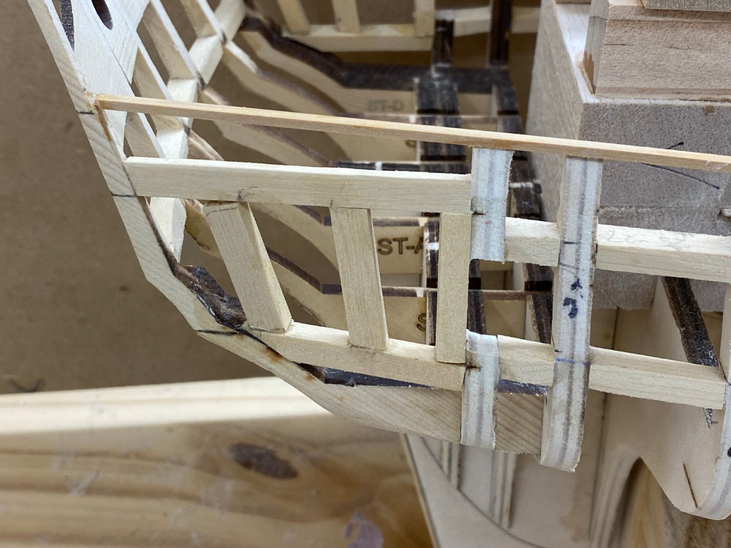
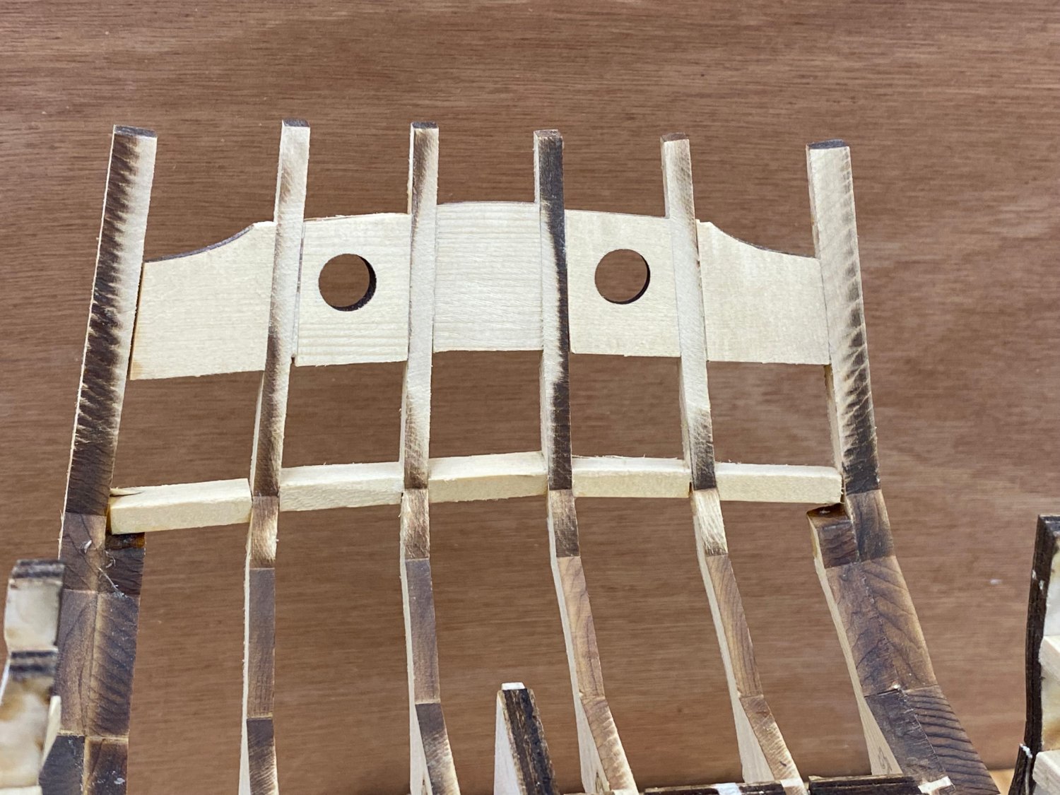
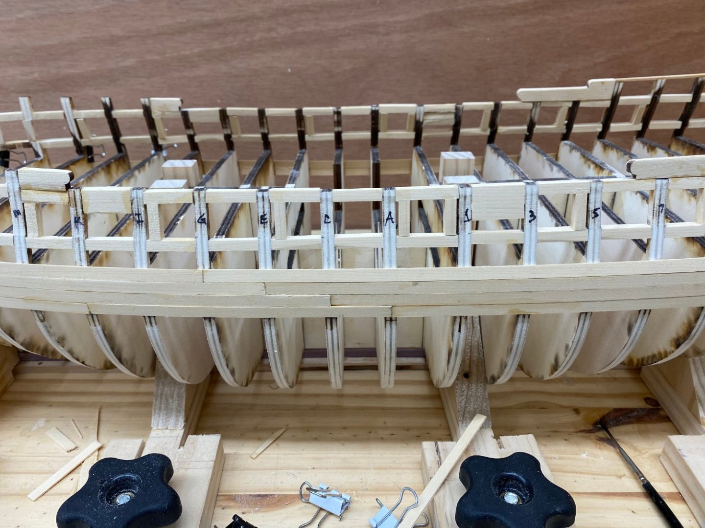
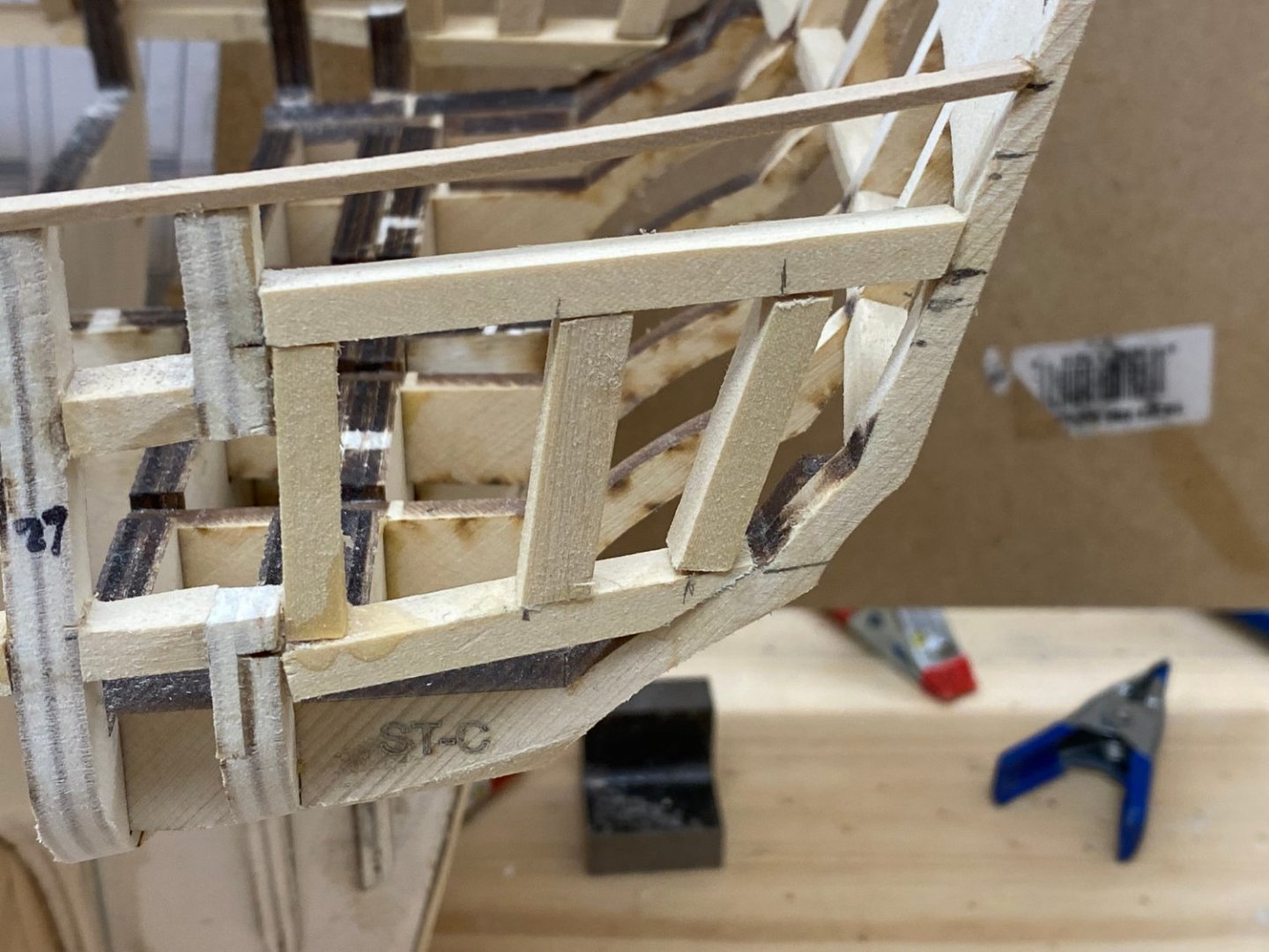
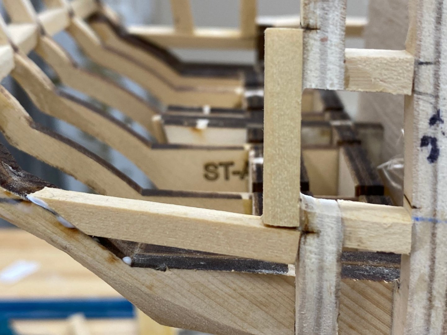
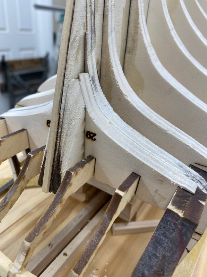
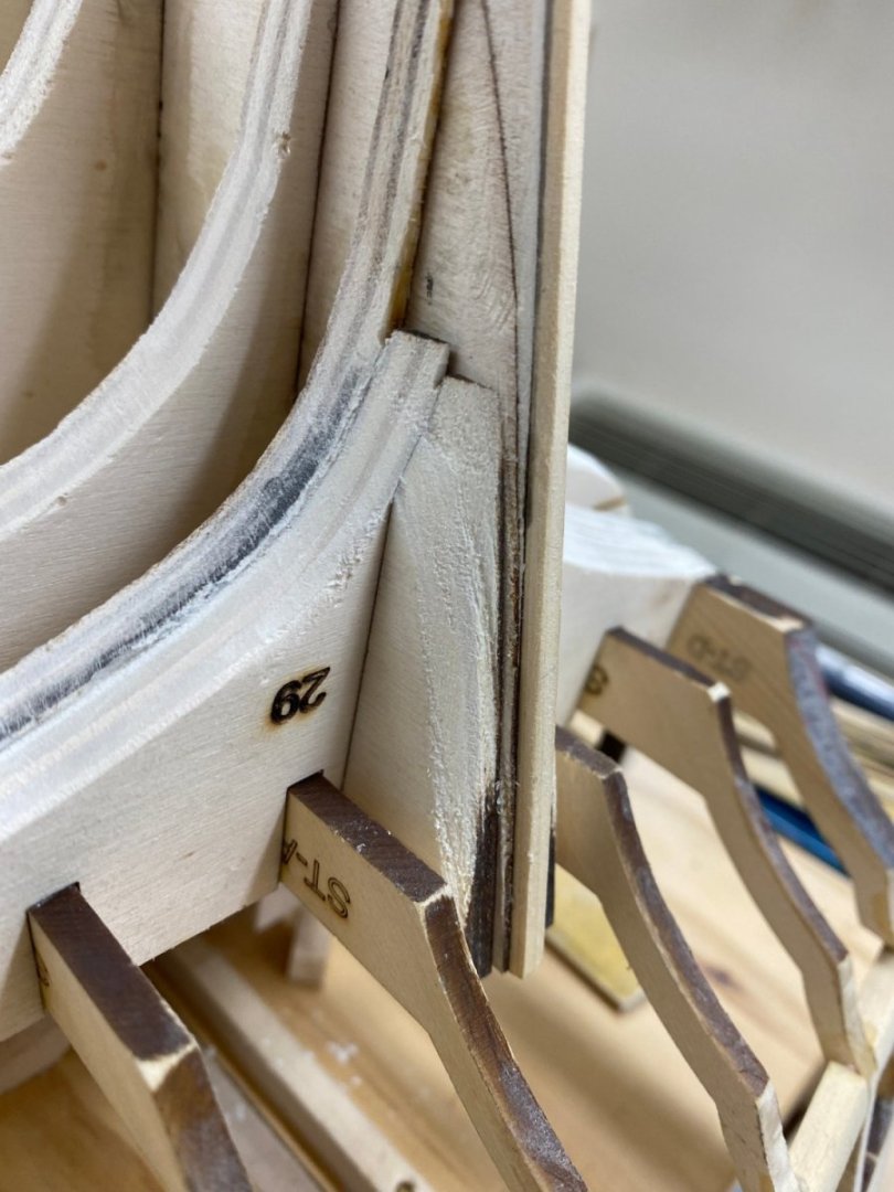
For those who might build the Winnie later a word of advise about the cutting the bulkhead extensions for the aftermost gun port and the qgallery framing. Having done this now four times (twice on this hull and twice on the previous attempt) I think I have found the preferred (IMHO) sequence. The first piece to add is the lower horizontal piece that runs from the bulkhead 29 to the stern transom. The laser marks on BH 29 are for the upper surface of this piece as the plans show. Then add the vertical piece that forms the aft end of the last gun port. This piece runs from the top of the lower horizontal piece to the laser mark near the top of BH 29. Only apply glue above and below where the horizontal pieces that are the top and bottom of the gun port. When this glue has dried then carefully cut out the bulkhead extension, starting with the top cut. If no glue leaked down the bulkhead extension should be free and here is what it should look like. Now add the upper horizontal piece which sits on top of the gun port side just added. Then add the more or less vertical pieces that complete the qgalley framing. Do not ask me how I know this procedure is less painful that others.
- 389 replies
-
- 2
-
-
- winchelsea
- Syren Ship Model Company
- (and 1 more)
-
As with the stern fillers by the rudder post there is no mention of the fillers above the lower transom planking but... So I fashioned some out of basswood but am not going to glue them in until I get the lower transom planking done. According to what I have read the curve of the transom planking will help to determine the exact shape of these fillers. Maybe I will wait until I am planking this part of the hull to give them their final shape.

- 389 replies
-
- 6
-
-
- winchelsea
- Syren Ship Model Company
- (and 1 more)
-
Although I could not find a reference in the instructions about the stern fillers along side the stern post I did find this picture in Chuck's build log: To paraphrase Admiral Lord Nelson before the Battle of Trafalgar "A modeler can do little wrong if he makes his model look like Chuck's" So I added the stern fillers and faired them in. Next up are fairing in the stern timbers and the fillers that go just where the lower transom planking will go.
- 389 replies
-
- 3
-
-
- winchelsea
- Syren Ship Model Company
- (and 1 more)
-
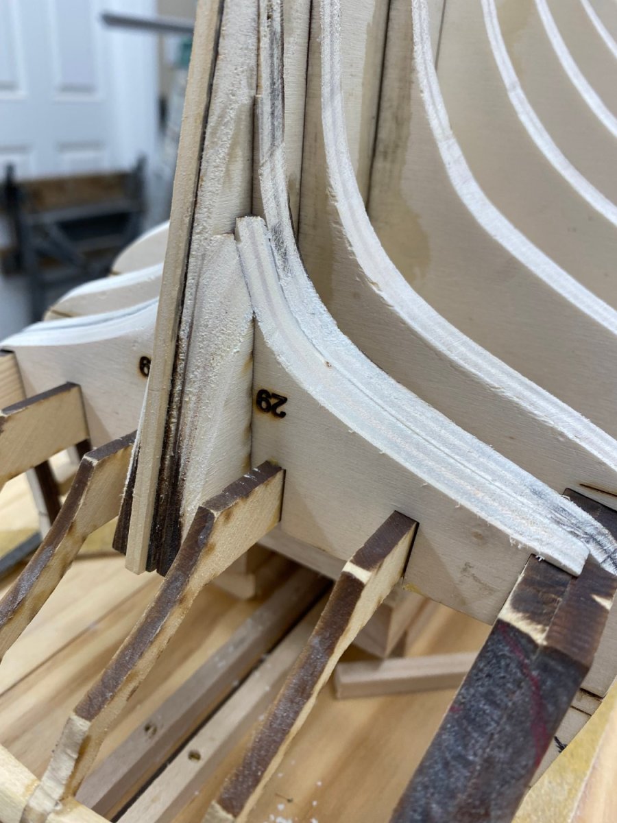
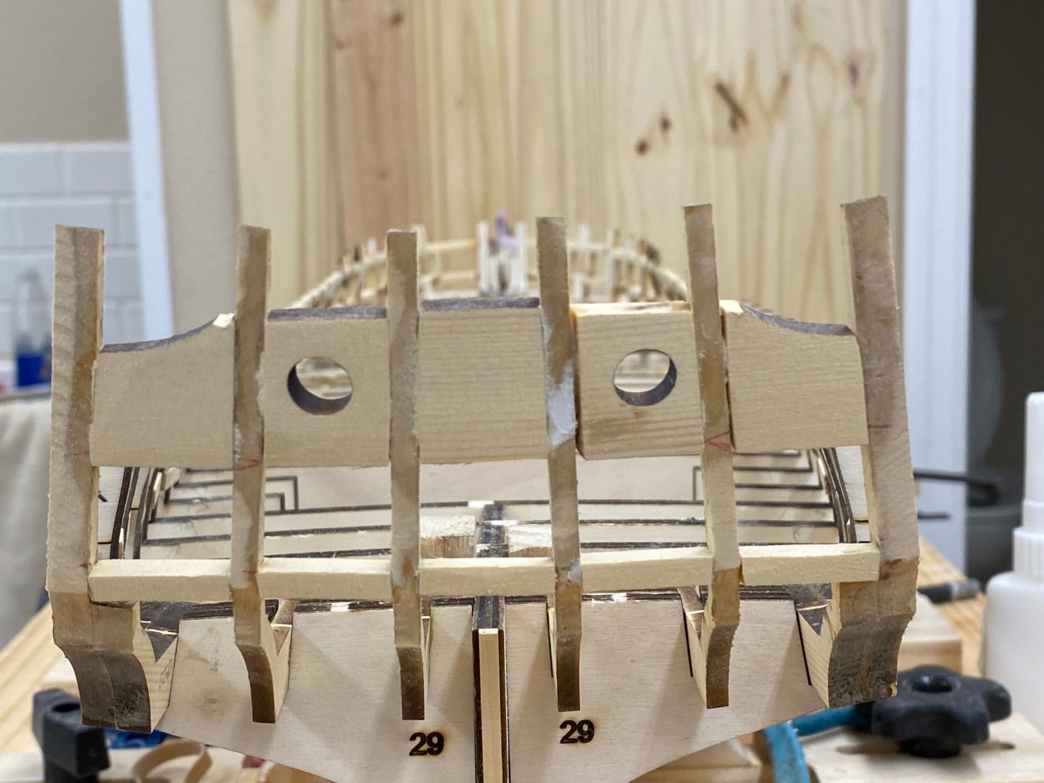
I have no idea what I did to get box above to appear and am equally clueless about how to delete it. Anyway, I have the transom thinned down to near the 3/32" so I am called stage 2 of the thinning complete. Now I have to fair the outer stern timbers (Timber C) and bulkhead 29. I am adding the paper templates for the C/D timbers again to get the contour of the C timber but will have to turn the hull over to fair bulkhead 29 then back upright to add the qgalley framing. Oh well, I am getting pretty good and changing the hull orientation around.
- 389 replies
-
- 3
-
-
- winchelsea
- Syren Ship Model Company
- (and 1 more)
-
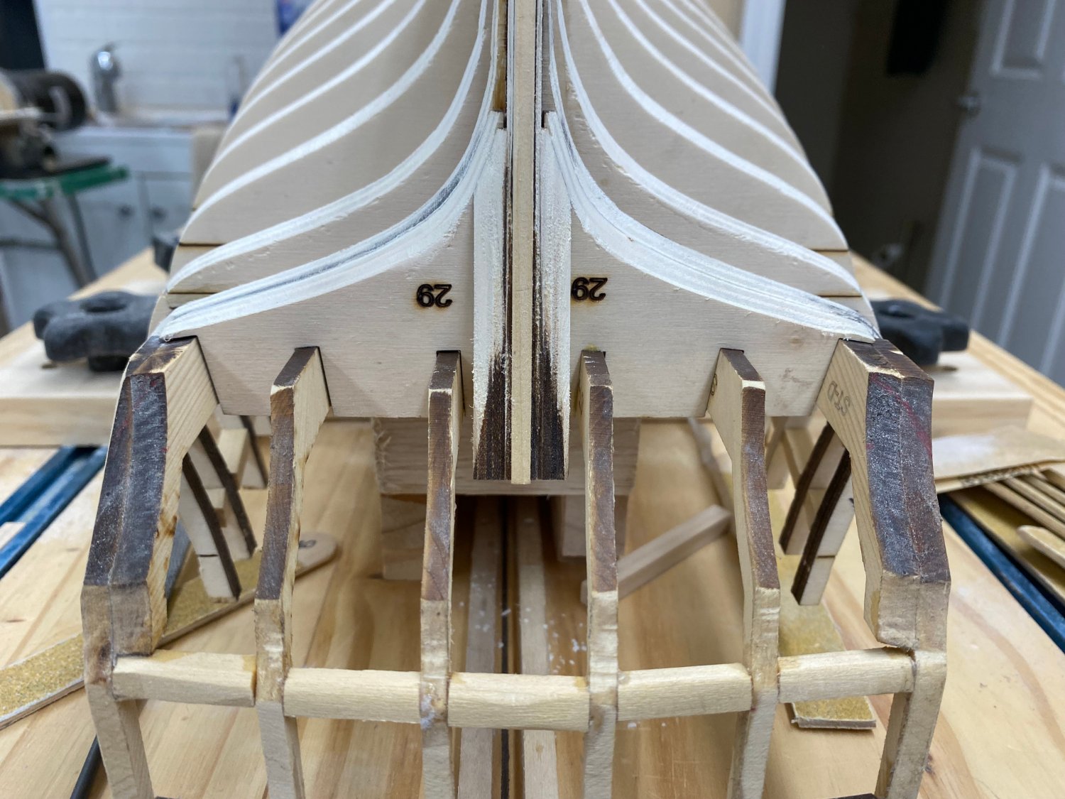
What I am calling Stage 1 of the thinning of the transom is complete. I define Stage 1 as getting all the excess material beyond the stern timbers removed. That getting the upper fillers to about 11/64" think. Instructions say they need to be 3/32 (6/64) so I need to take off another 5/64s or so. I will try and distribute that evenly across the front and back but becuase the back is easier I will probably not be successful but there probably is no easy way to tell. So here is what the transom looks like at this point.


- 389 replies
-
- 2
-
-
- winchelsea
- Syren Ship Model Company
- (and 1 more)
-
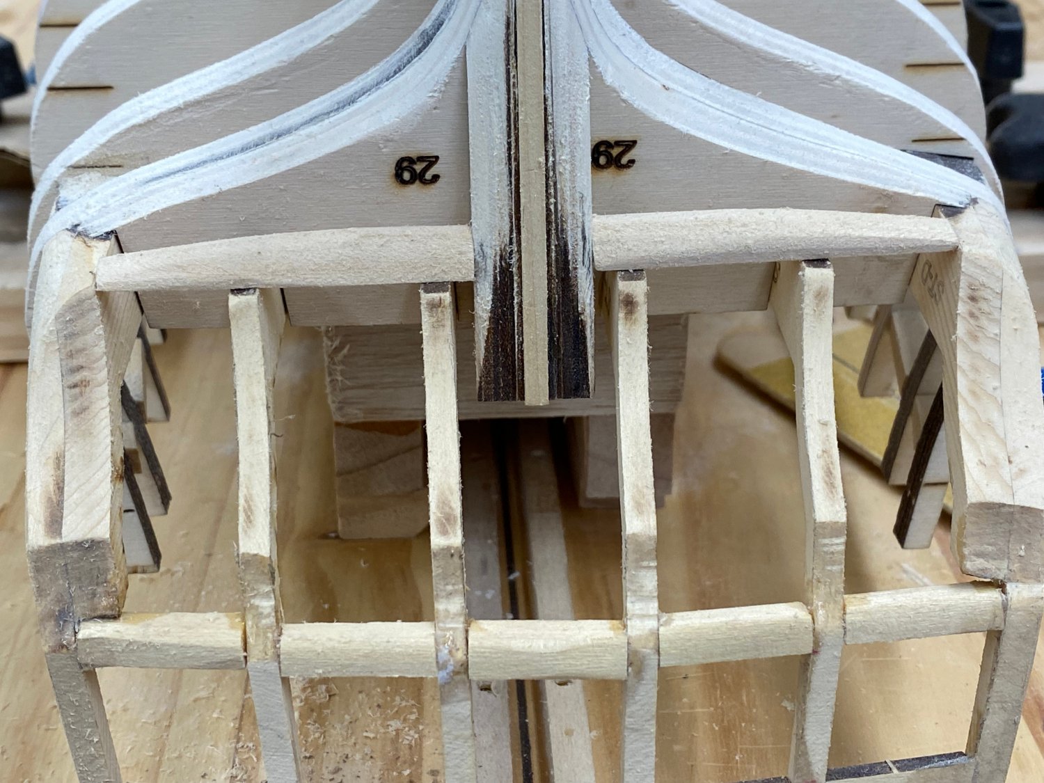
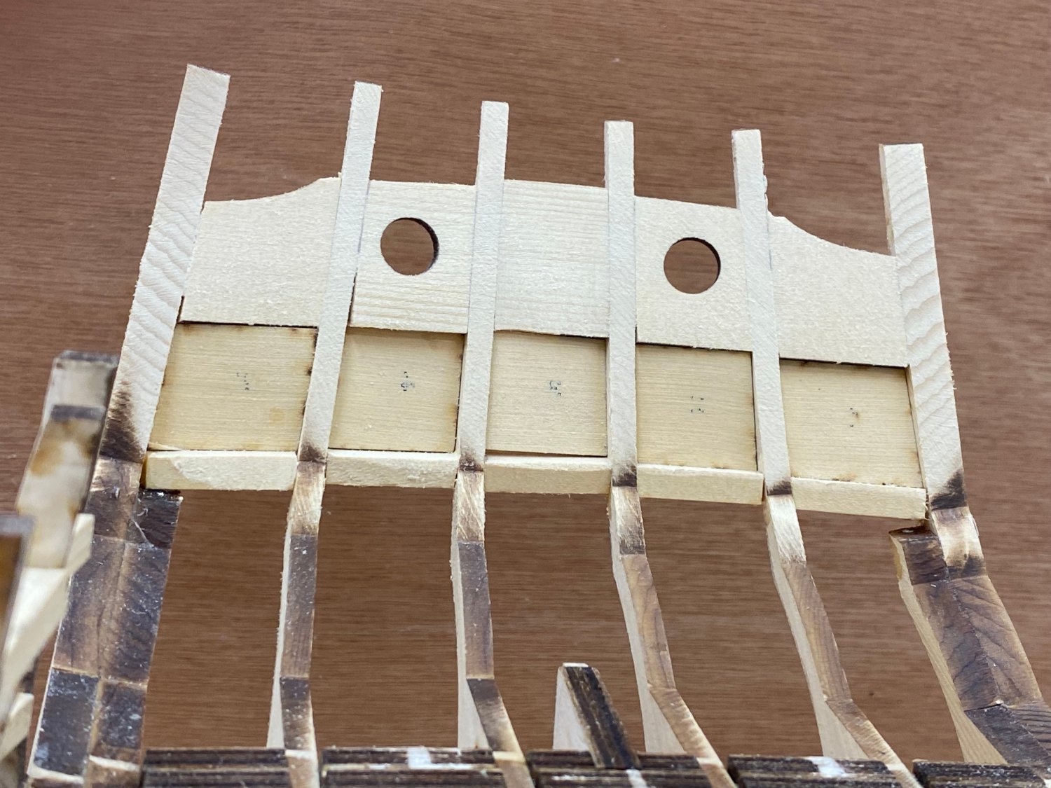
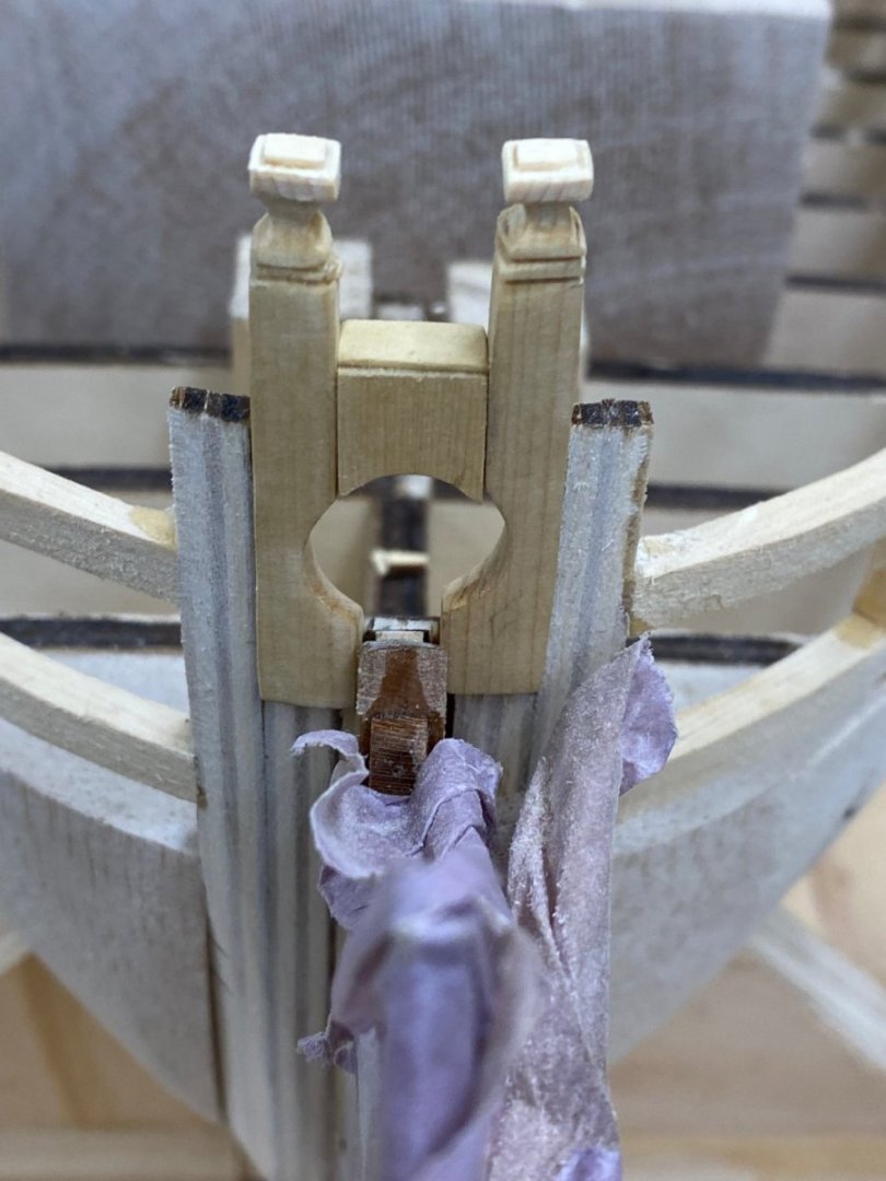
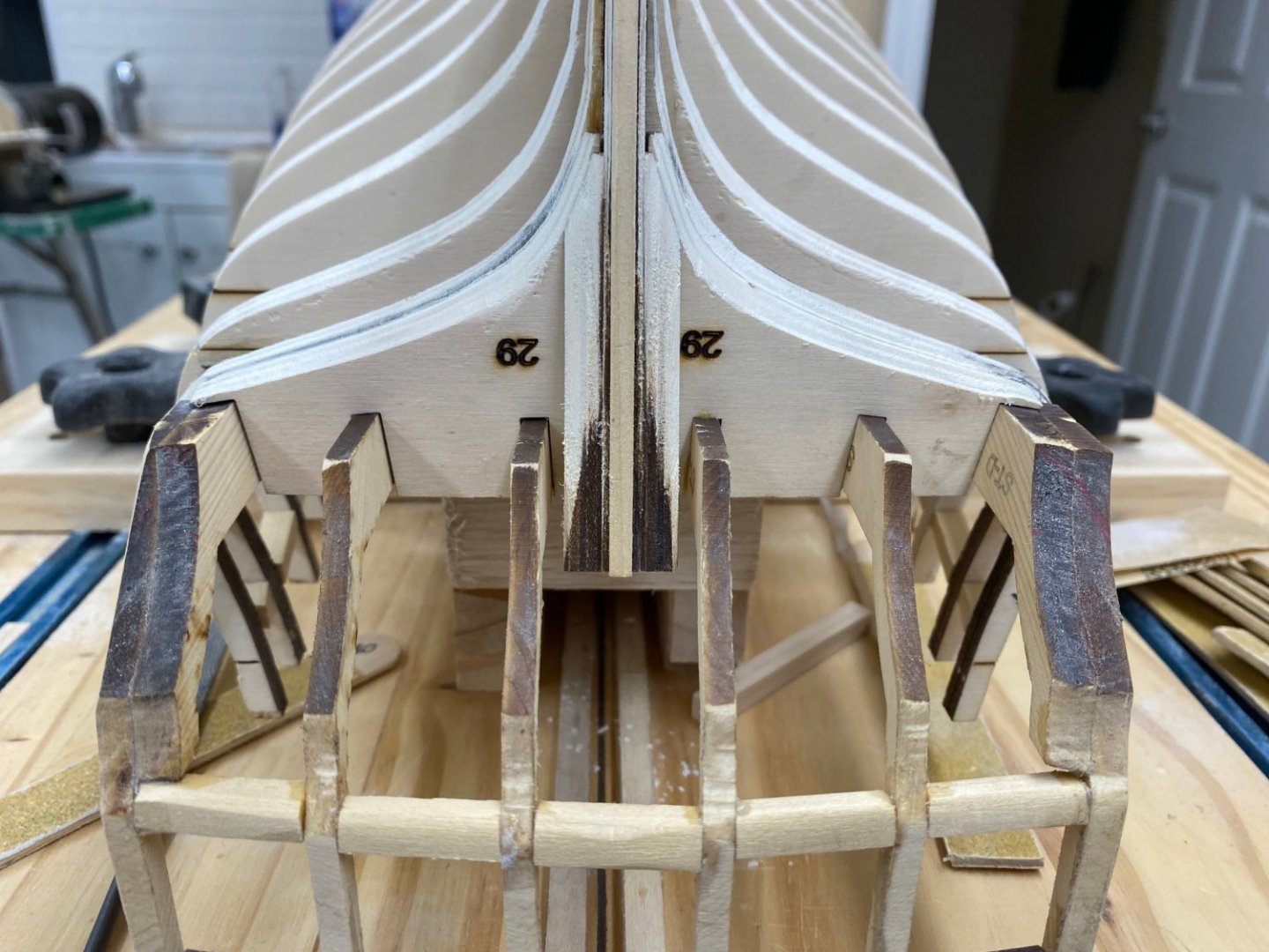
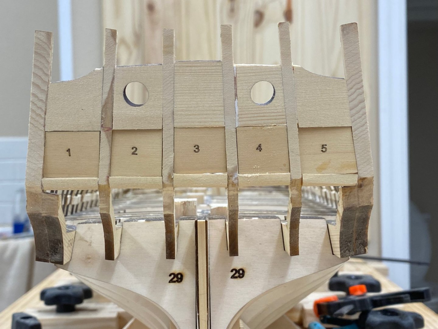
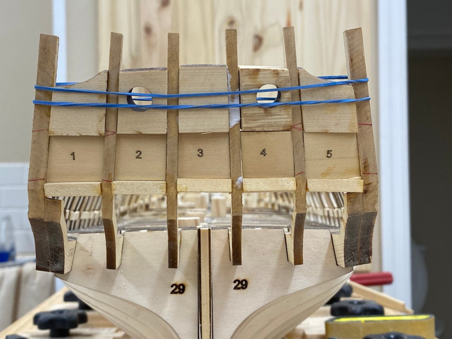
Thanks Glenn - I have the stern timbers and sills and spacer "done". And yes, I worked from the outside the stern to get things ion place. In fact here is what the stern looks like while I wait for the glue to dry (overnight tonight). The number 4 slot looks to be off a little but I think I got the others pretty close.

- 389 replies
-
- 5
-
-
- winchelsea
- Syren Ship Model Company
- (and 1 more)
-
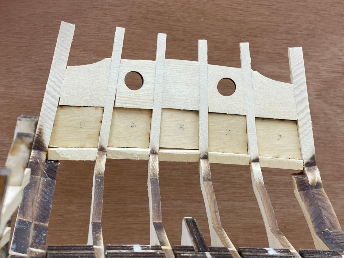
Thanks Chuck. I am working from the outboard side to place the sills and fillers. The template is only to see that I get the stern frames in approximately the right place. So far the alignment has been correct (per the template) if I push the stern frames completely down into the notch and have it flush with the forward side of bulkhead 28 so the framing appears to have been successfully laser cut and assembled.
- 389 replies
-
- 1
-
-
- winchelsea
- Syren Ship Model Company
- (and 1 more)
-
I put a digital level on frames 28/29 and got a reading of .3 degrees so I figured that was close enough.
- 389 replies
-
- 3
-
-
- winchelsea
- Syren Ship Model Company
- (and 1 more)