HOLIDAY DONATION DRIVE - SUPPORT MSW - DO YOUR PART TO KEEP THIS GREAT FORUM GOING! (Only 13 donations so far - C'mon guys!)
×


cdrusn89
-
Posts
1,915 -
Joined
-
Last visited
Content Type
Profiles
Forums
Gallery
Events
Everything posted by cdrusn89
-
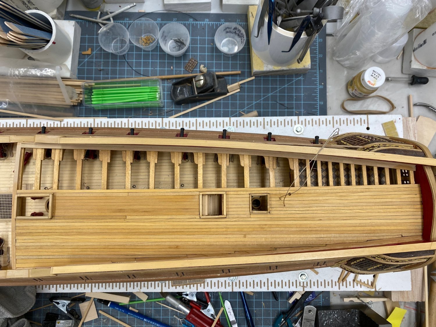
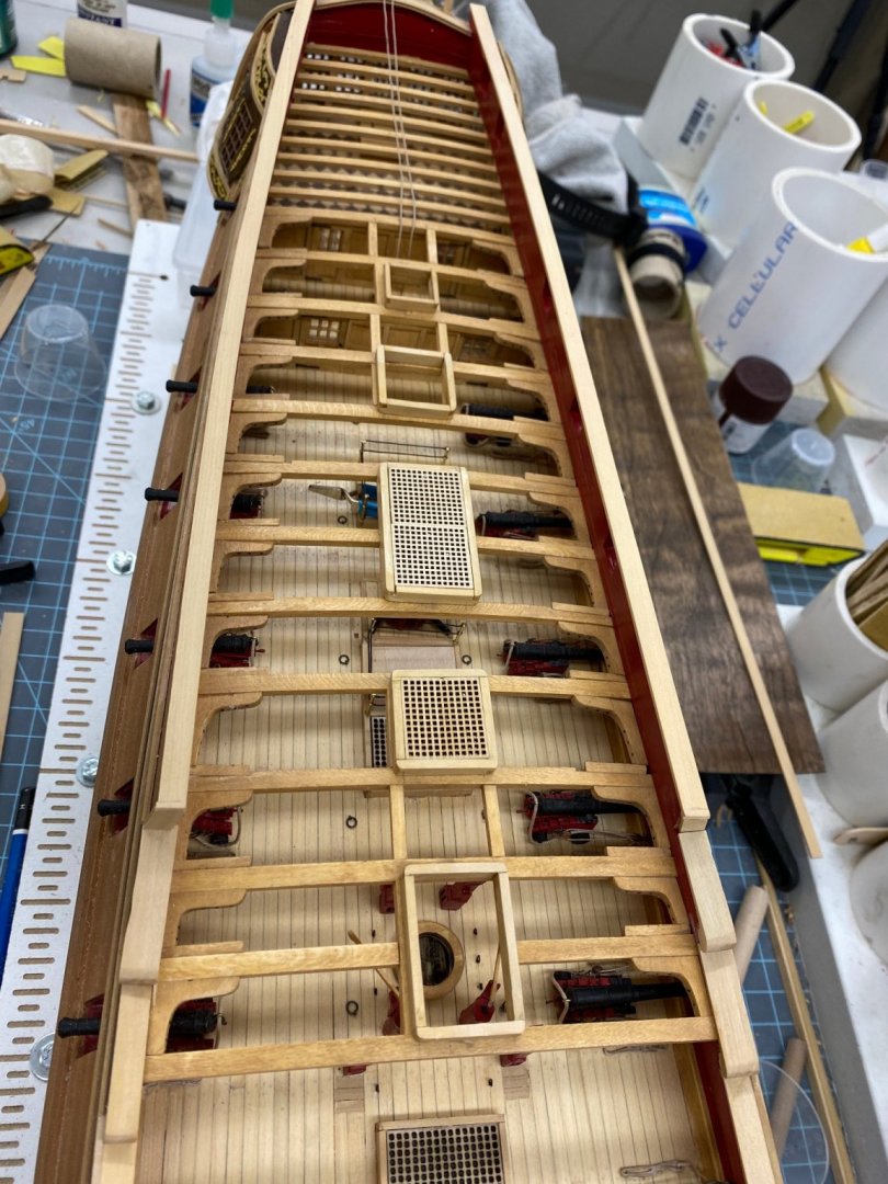
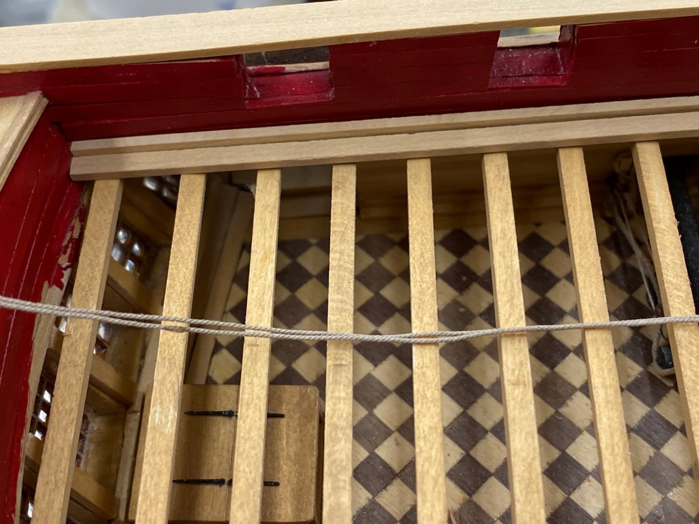
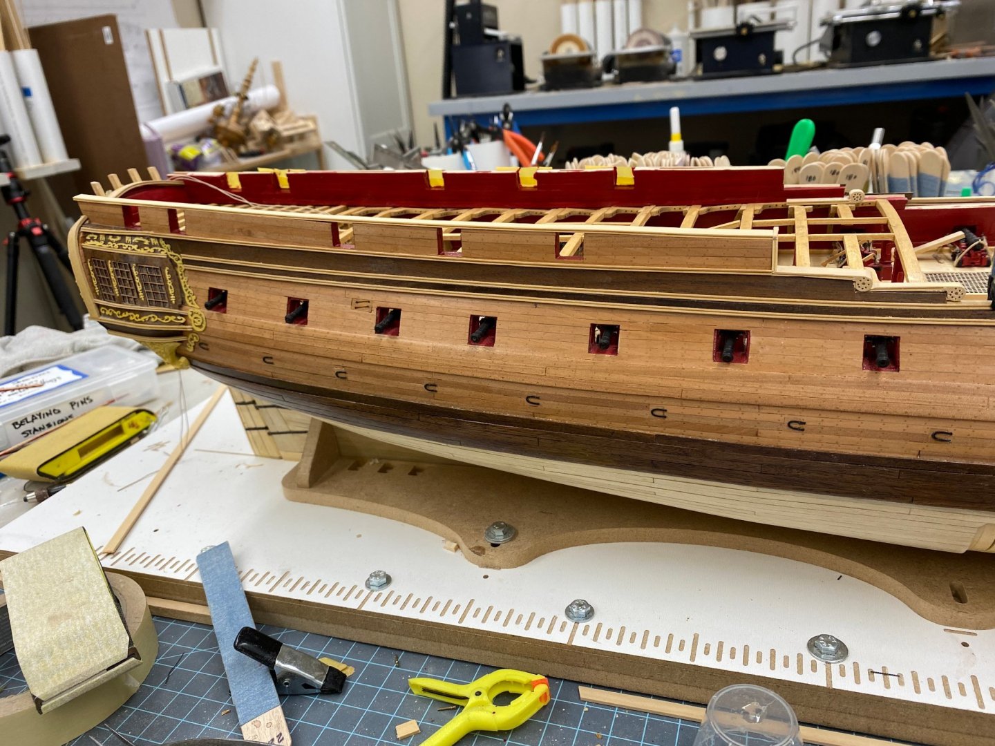
 The quarterdeck planking is complete and a first pass with 120 grit sandpaper has been done. I will do a 220 grit sanding and then Wipe-on-Poly (2 or 3 coats). It is not a uniform in color as I had hoped but it is what it is and with all the furniture and guns it will be pretty much "hidden" anyway. I will install the hatches but nothing else at this point. Too easy to knock something off with the wheel, main and mizzen rails and binnacles "sticking up". My intention is to plank the forecastle, work the channels and chain plates then move on the "fun" at the bow.

- 370 replies
-
- 2
-

-
- Model Shipways
- Confederacy
- (and 1 more)
-
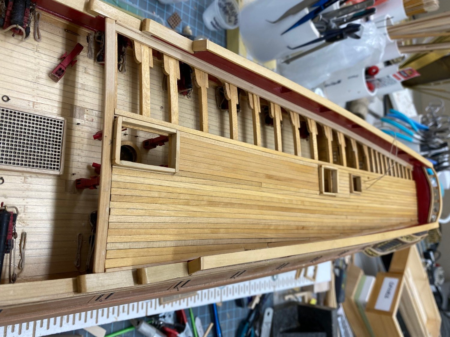
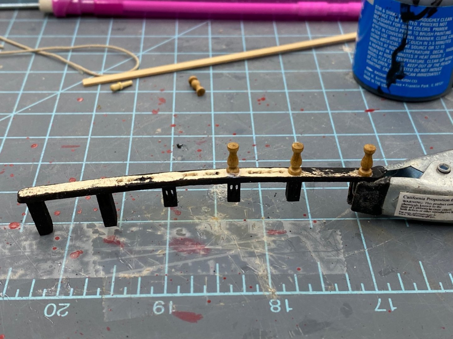
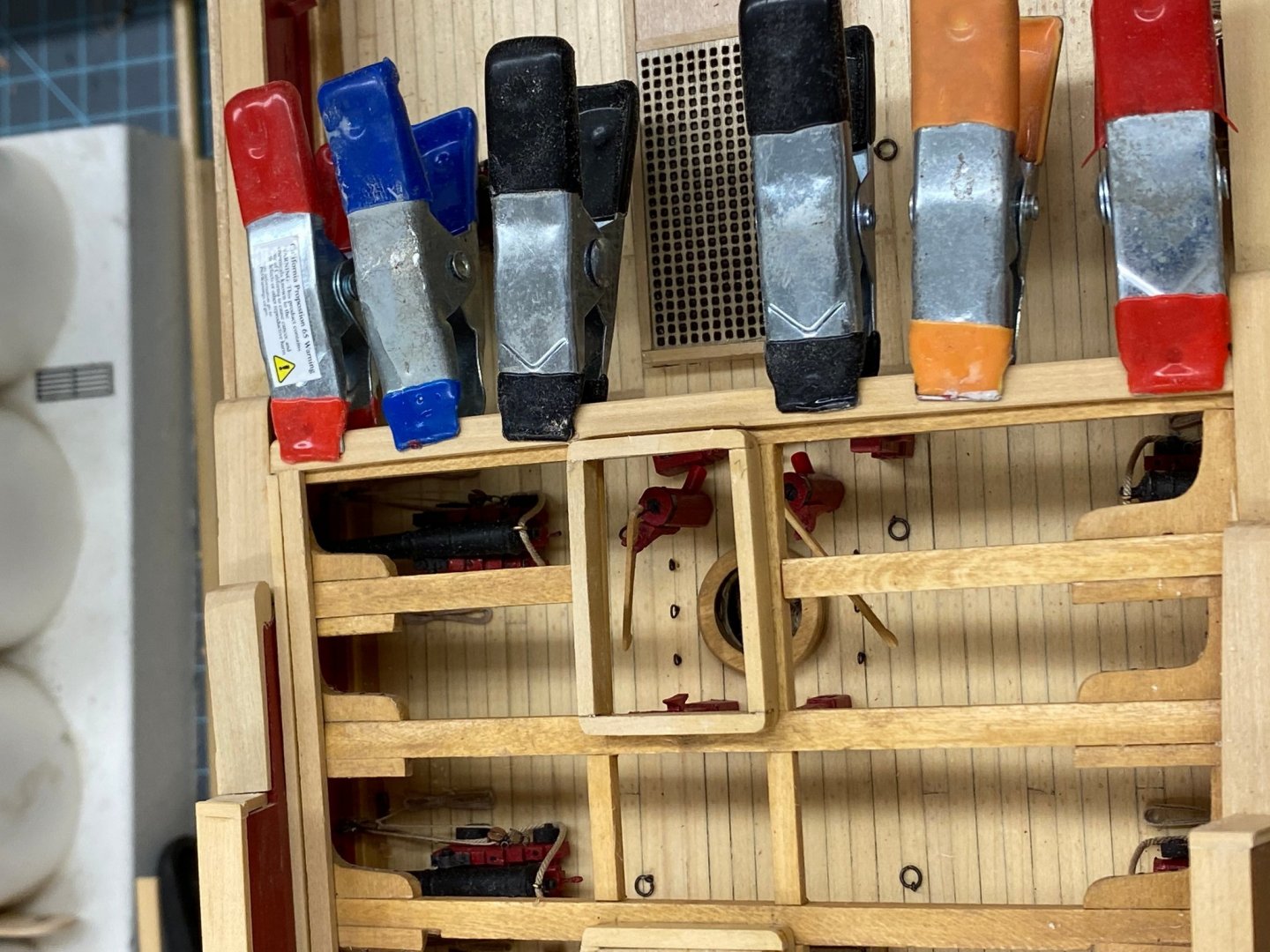
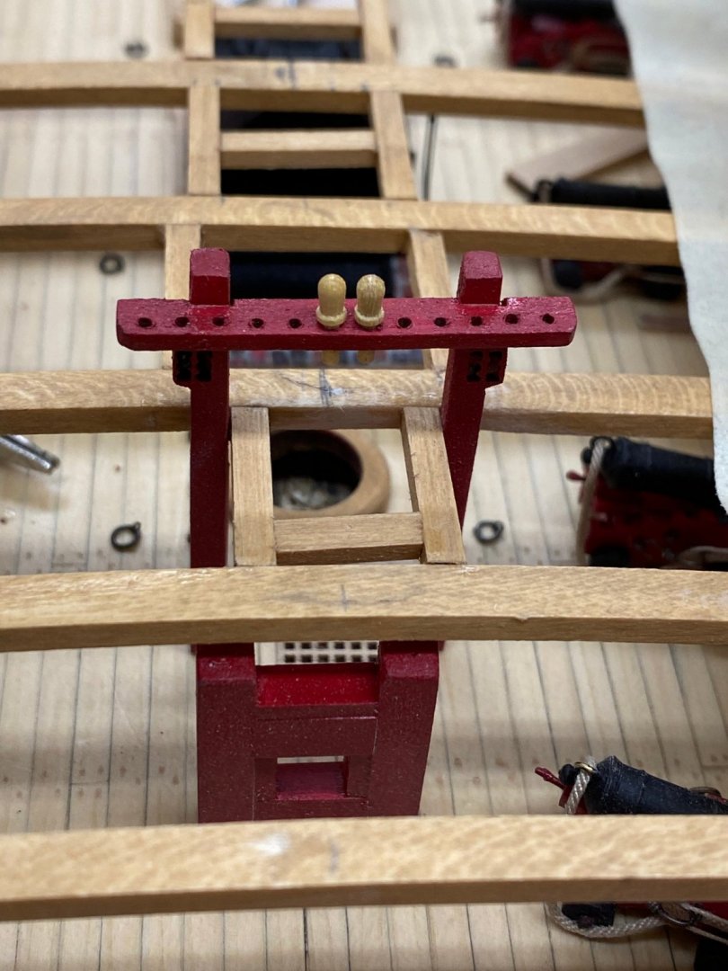
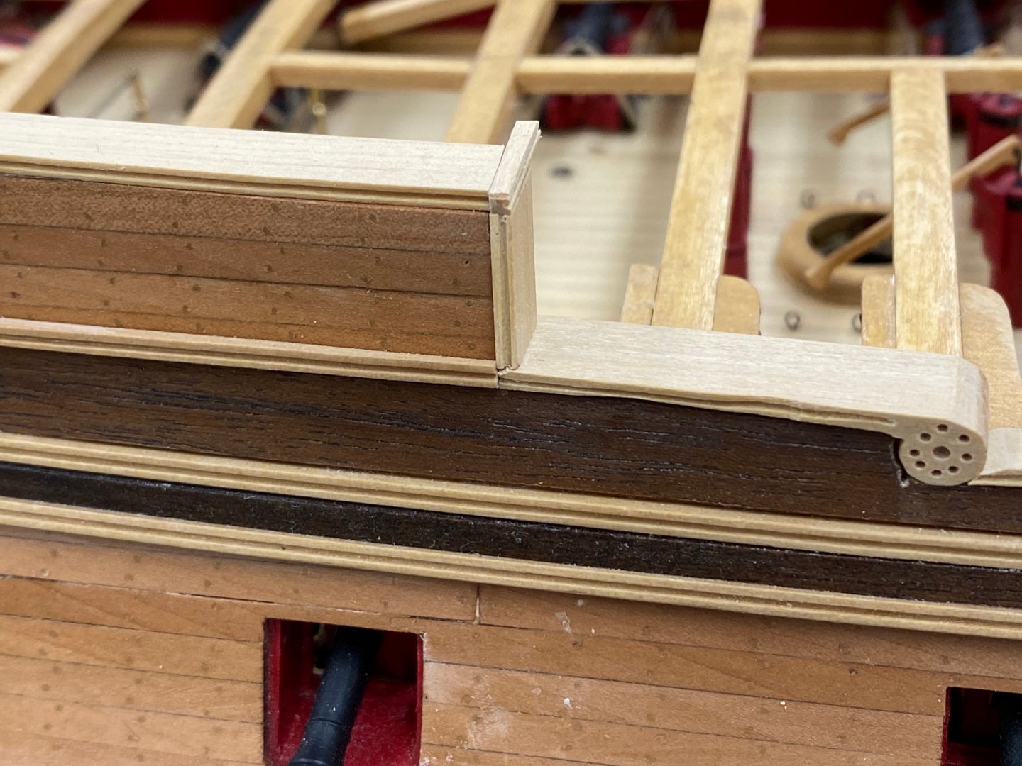
Yes I know it has been a long time since I posted something but the good news is I had no done much since I last posted in early February. Between the window seat and crown molding in the MBR, painting the living room and a cruise on the Mississippi there really has not been much opportunity to work on the Confederacy. I have five weeks until the next "vacation" at the very end of April so I "plan" on making a serious effort to make some progress. I even paid for a 7-day cruise for my girl friend and her cousin from Canada so I ca have a week of uninterrupted shipbuilding where her cousin in is here. So I am working on the quarterdeck planking and the deck fixtures that go on that deck. As you can see in the previous post I had decided to make the decking between the main mast coaming and the companionway coaming continuous rather than trying to get a bunch of really short pieces to fit and hold a centerline. This means that I will be planking the quarterdeck about 2/3 of the way across. I have looked and you can still see some (maybe most) of the details on the gun deck but I did not want to have the ship's wheel (for instance) sort of "hanging out there" on one side as was shown in the instructions. I also decided to not try and "plank around" the main rail so I have fabbed it with only the two supports that are on the port side extending down onto the deck beam. The other four will just rest on the deck planking. Here is a picture of the main rail "under construction". I have extended the quarterdeck planking almost to the point where I will have to figure out how I going to handle the "nibbling". Given that much of this planking is going to be covered by gun carriages I am tempted to just sand the planks to fit and not worry about sharp points but I will wait until I have the planking completed across the treansom to make that decision. Here is the quarterdeck planking as it is now.

- 370 replies
-
- 2
-
-
- Model Shipways
- Confederacy
- (and 1 more)
-
I managed to get another row of planking on each side and set the two hatches on the deck to see how they look. I had considerable issues getting the new planks on the starboard side to lie flush with the set of six. I will have to sand the quarterdeck to get things more level once I have all the deck planking in place but before any more of the "furnishings" are installed. I decided to go ahead and remove the lower parts of the main rail since planking (not to mention sanding) around them would not be simple matter. I will have to modify some of the pieces to sit on the planking rather than attaching to a deck beam. Hopefully not an insurmountable challenge. Here is the quarterdeck with the two hatching sitting approximately where they will go.

- 370 replies
-
- 1
-
-
- Model Shipways
- Confederacy
- (and 1 more)
-
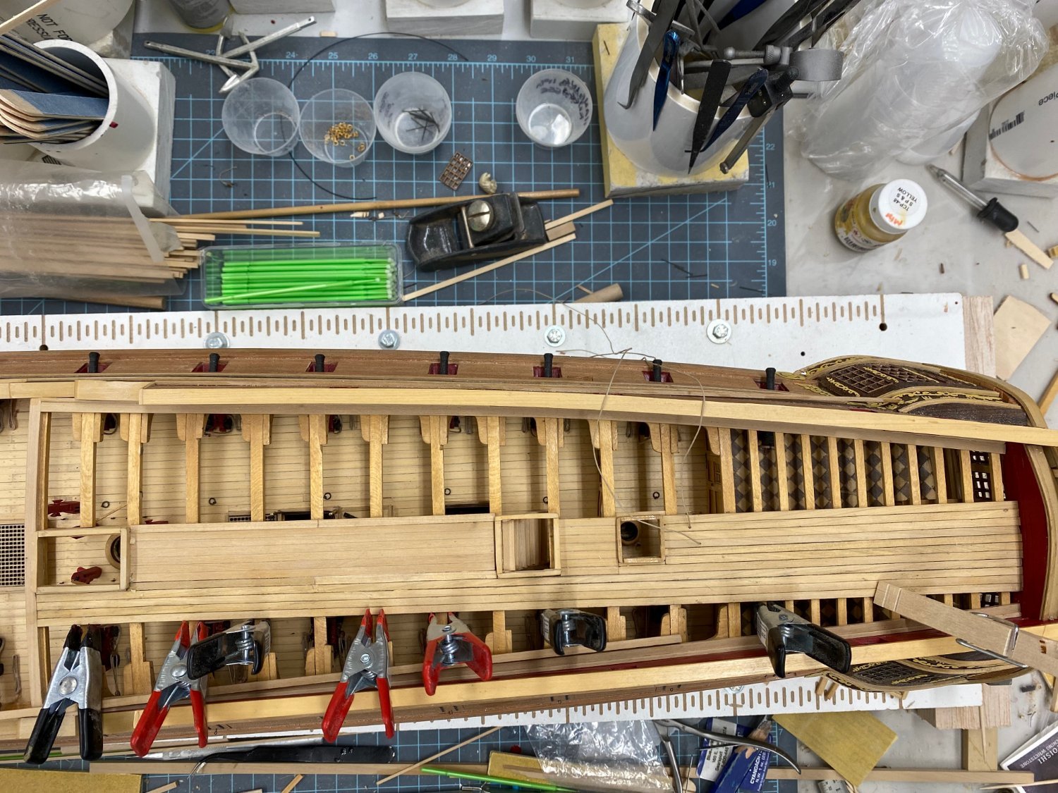
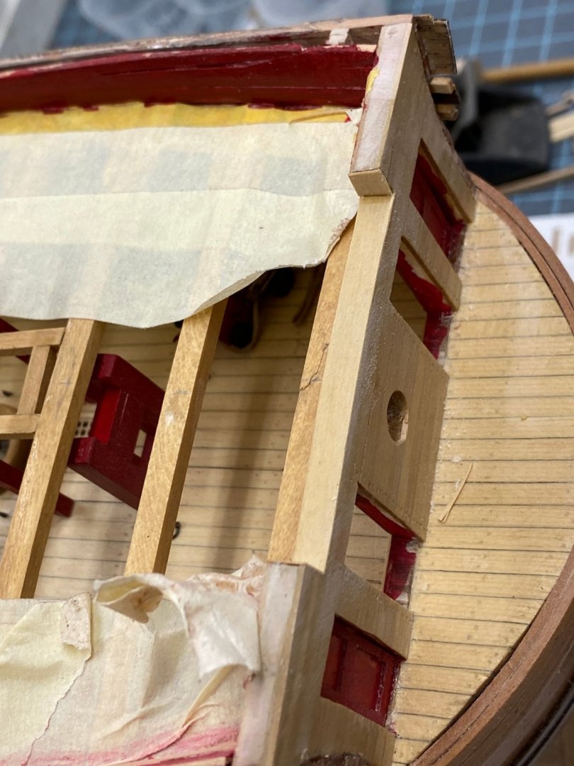
Sorry everyone - I have been "away" for a good while now but all is resolved and I am ready to get back to completing Confederacy. When we last say our intrepid ship modeler he was just starting to plank the quarterdeck. Given all the hatch and other coamings this became more difficult (at least for me) than planking the gun (aka main) deck. I was going to have to cut a bunch of really short pieces and fit them between the coamings, trying all the while to get them parallel with the centerline. As I started this process it became obvious that I had not taken enough care in manufacturing and location of the coamings around the mast and companionway leading down to the gun deck. The should be a clear run of planking that would run down each side of these coamings and be parallel to the centerline. As installed this was not possible because the width of the two coamings were about .1 inches different and they we not mounted centered on the centerline. My solution was to remove the coamings, adjust the widths (disk sander) carefully and remount them. I used the laser level to (hopefully) establish the centerline and glue to coamings down accordingly. I also decided to plank the area between these two coaming without regard to the two hatchways that are located between them. This caused a "redo" of those coamings with smaller stock so they would retain the required height above the deck. Here is where I am at this moment. The two new hatch coamings are ready but I need to add at least one more row of planking to each side so the area is wide enough. I have decided to fully plank the port side and enough of the starboard side to support the ships wheel and binnacles without using fillers.
- 370 replies
-
- 2
-
-
- Model Shipways
- Confederacy
- (and 1 more)
-
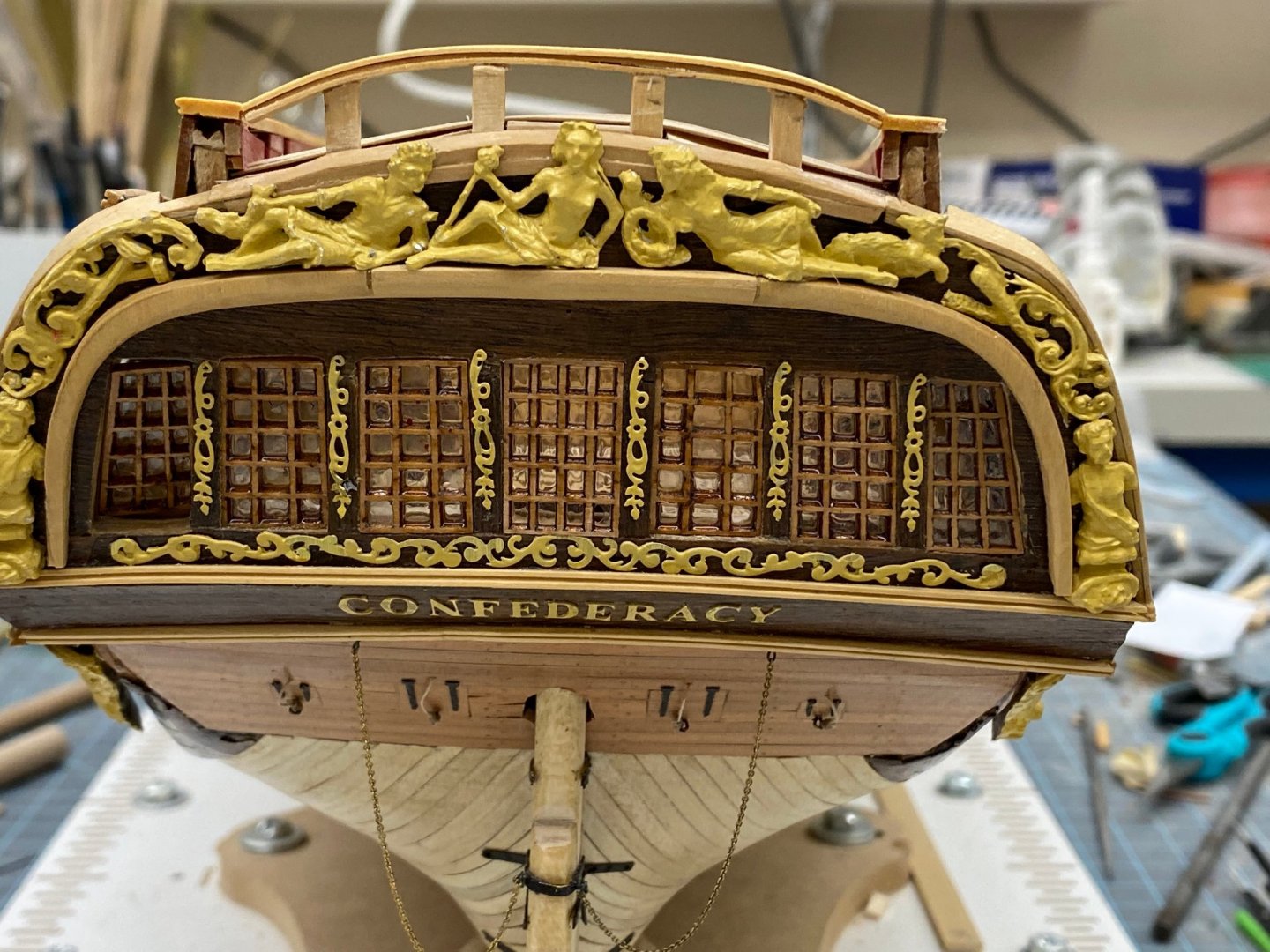
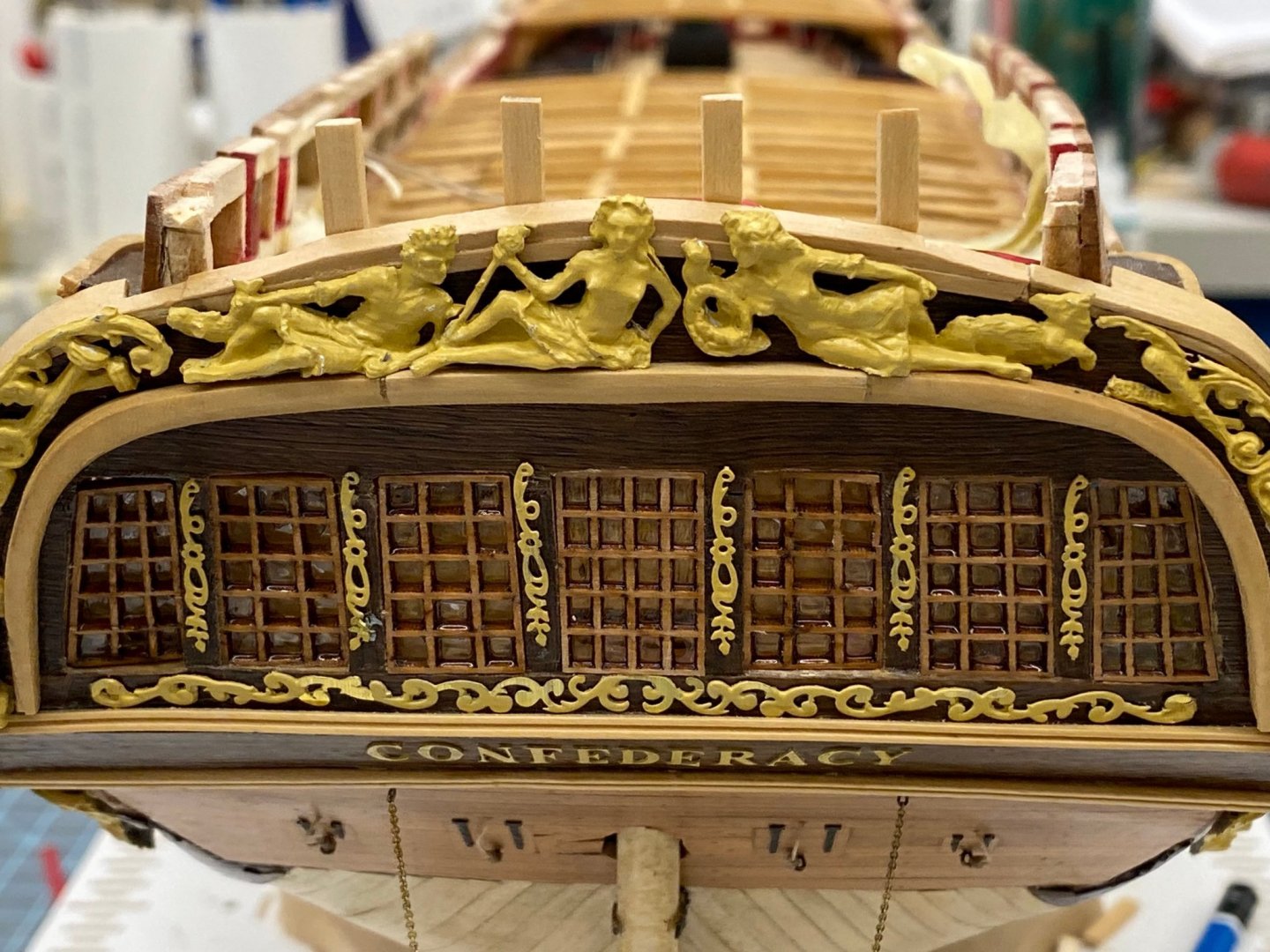
With the stern cap rail finished I decided to hit the quarterdeck rail with Wipe-on-Poly before moving on to forecastle rail. So here is what that looks like. And here is the stern with the stern decorations back in place. Not as smooth a curve as I might like but...

- 370 replies
-
- 4
-
-
- Model Shipways
- Confederacy
- (and 1 more)
-
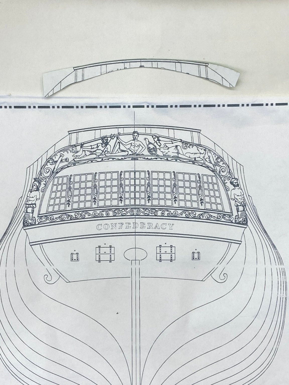
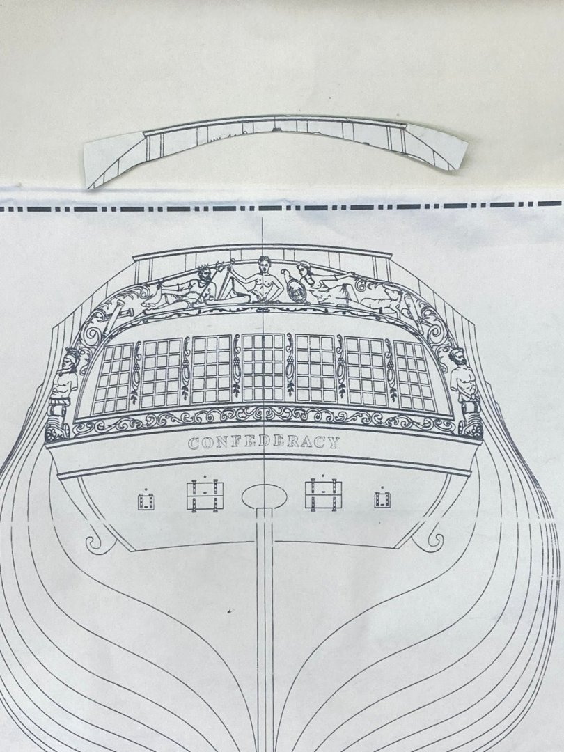
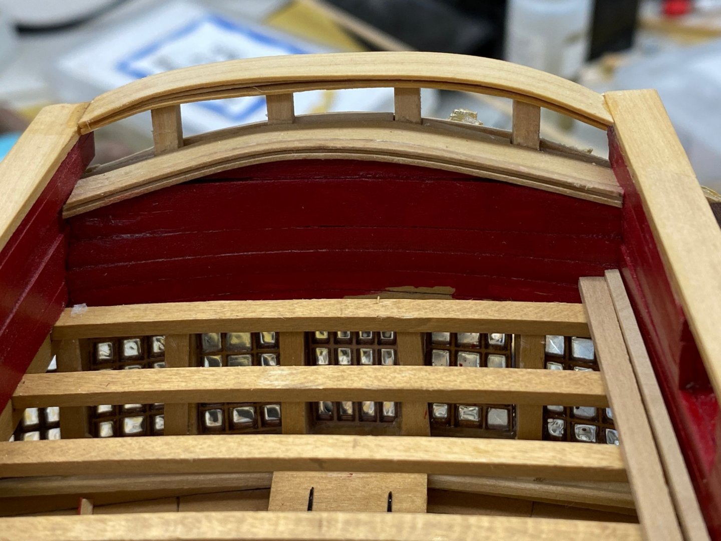
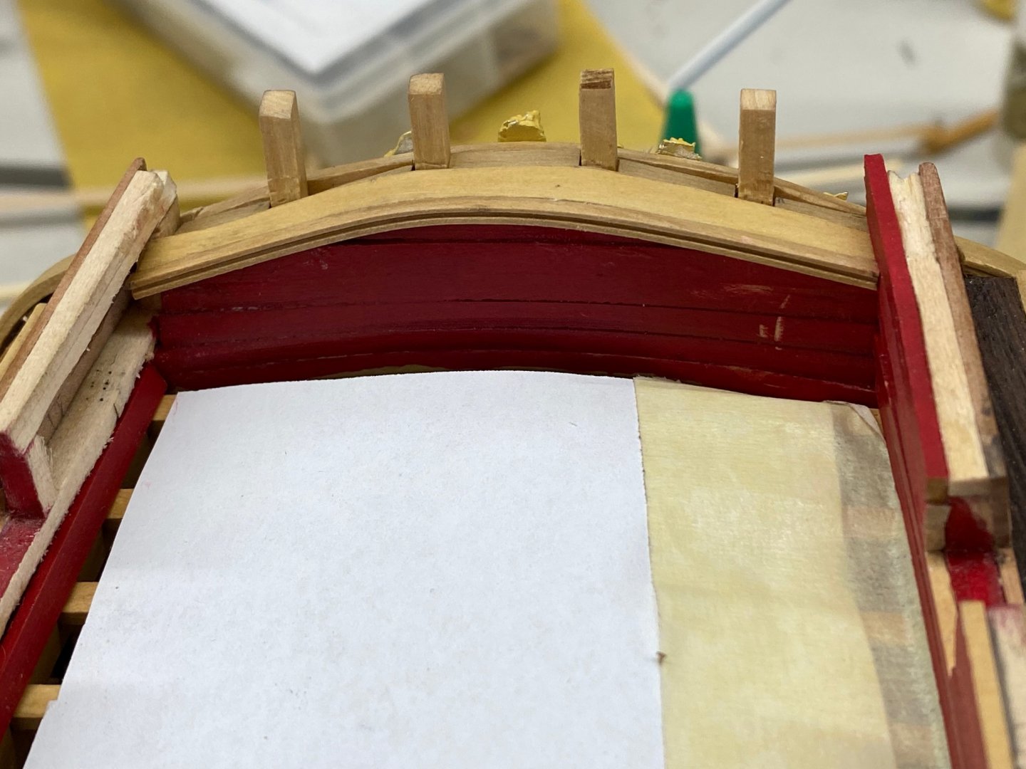
I have been struggling with the aft cap rail for what seems like weeks and now that I look at the previous post I see that it has been two weeks. I guess that working again has taken a tole on the model building. Anyway I finally came up with a plan and actually managed to execute it more as less as planned. First time for everything. Since I am making the cap rail from boxwood instead of basswood (aka limewood) it is considerably stiffer than the basswood and getting it to bend as described in the instructions was pretty much an exercise in futility. In the end I made a copy of the plans and cut a template for the aft cap rail and used that to adjust the height of the stern timbers. I tried soaking and bending some boxwood but could not get a curve that would match what I needed. My wood bending skills obviously need improvement. So I decided to use three thin (.0200" more or less) strips of boxwood, two 1/4" wide for the top and bottom and a 3/16" wide piece in the middle to simulate the fancy molding on both sides. I adjusted one end to meet the side cap rail on one side and then glued that down. i used diagonal cutters to cut the other end a tiny bit long and then sanded to get it to fit on the other side. When I was satisfied I glued the piece down the rest of the way. Here is how looks on the inside. I have to glue two of the stern decorations back on before I take a picture from the stern - maybe tomorrow since the Dolphins and Jags are playing in London - game starts at 0930 EDT. Plenty of ship modeling in the afternoon.
- 370 replies
-
- 2
-
-
- Model Shipways
- Confederacy
- (and 1 more)
-
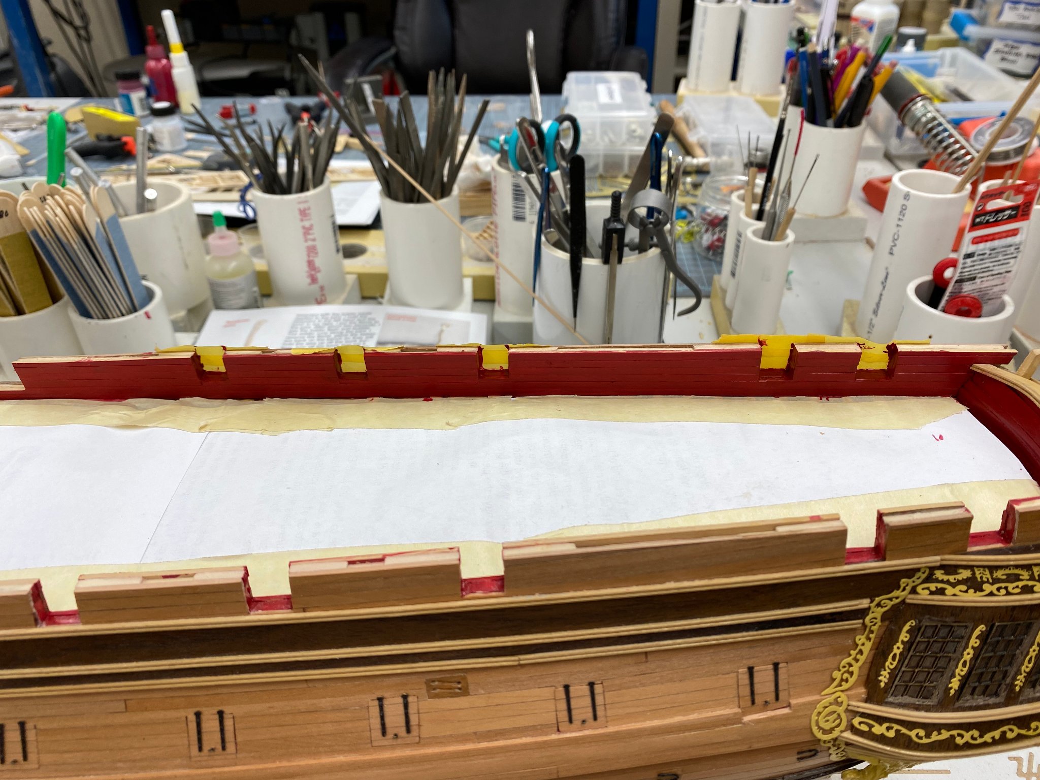
The more I looked at the bow the less I liked it. The wider cap rail (5/16") required to "cover" the width of the bulwark just kept bugging me. So I ripped off the one I had done (and took some of the interior planking with the cap rail) and started to thin down the bulwark planking. Unfortunately for me I used boxwood instead of basswood for the interior planking for some reason I can't (or do not wish) to remember and it was tougher than it should have been. I managed to get at least the upper half of the planking tapered to more or less 1/32" and I thinned some of the spare planking I had to replace what got ripped out when I removed the cap rail. Now I have it repainted and except at the very front the bulwarks are under .25". I can live with that. I am thinking at the bow I may add a "filler piece" across the corner between the cap rail and the beakhead rail. Here is the port side after thinning and painting. Instead of painting the beakhead I used the boxwood veneer I created for the aft rail to cover what will be under the beakhead rail. And not to be deterred from continuing aft while I mess around forward I installed the coaming for the quarterdeck, and dry fit the waterway and margin plank of the port side. I decided to do the quarterdeck planking in boxwood so am using boxwood for the waterway and margin plank. I am substituting 1/8" X 1/16" boxwood for the laser cut margin plank which by my measurement is less than 5/32" but more than 1/8" and almost completely straight. I am confident I can get them to conform to the very slight curvature on the quarterdeck (and the forecastle too for that matter). I have pieces long enough to cover the entire quarterdeck in one piece so I think I will not try and create my own scarph joints. The coamings Here is the port side dry fitting of waterway and margin plank. Still have to round off the inboard edge of the waterway. And for good measure here is the"starter plank just forward of the main mast coaming.

- 370 replies
-
- 3
-
-
- Model Shipways
- Confederacy
- (and 1 more)
-
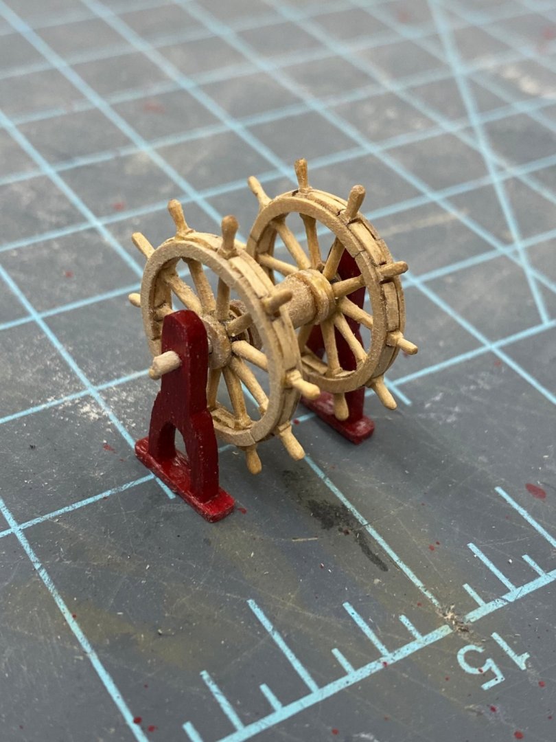
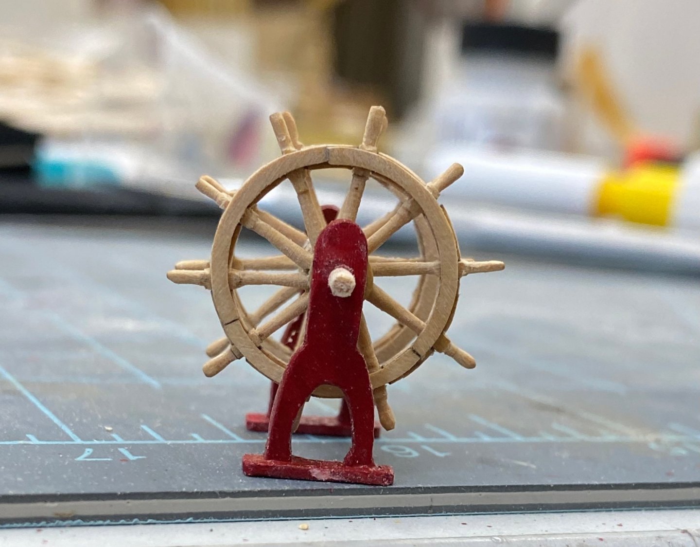
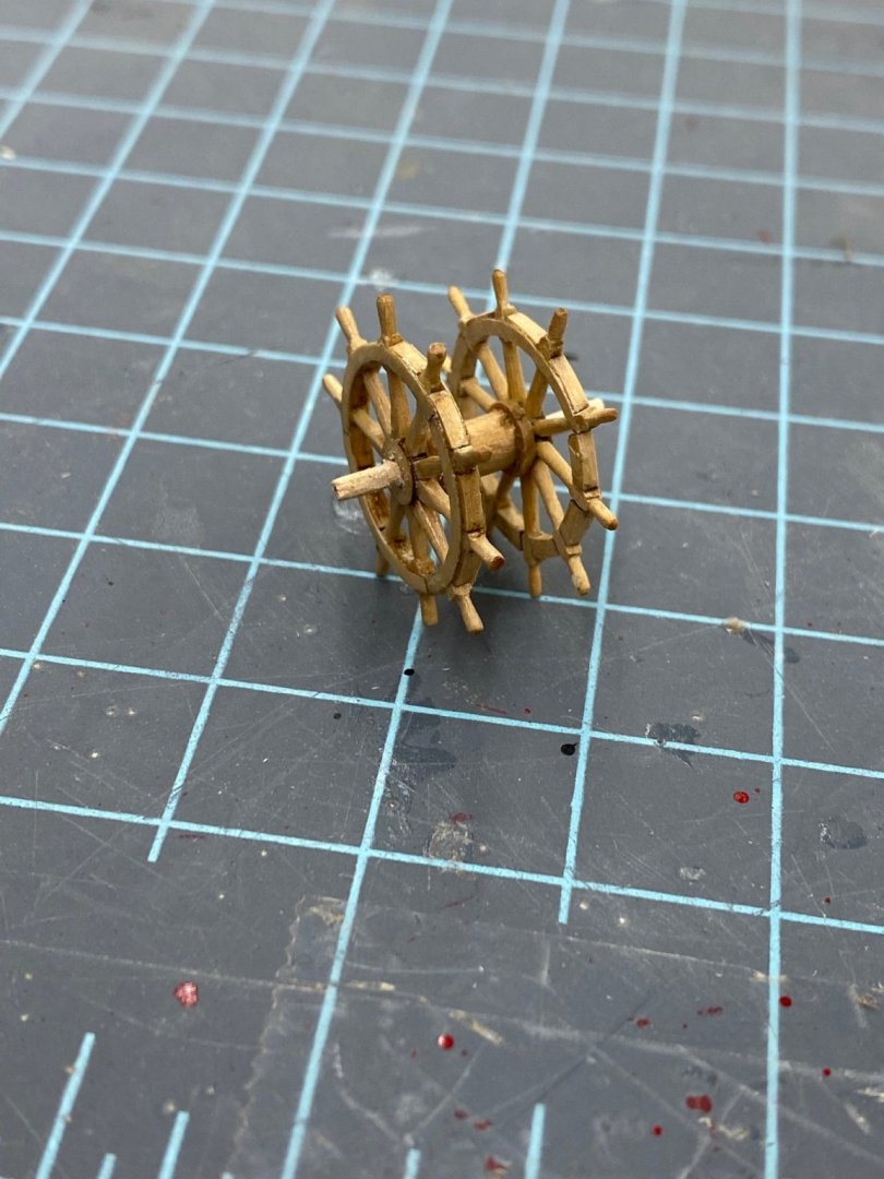
Finally got all the pieces for the ship's wheel(s) completed. Here the wheels are glued to the drum but the supports are not yet attached. I am going to put a coat of WoP on the wheels and drum before I glue things up and trim the shafts off at the ends of the supports (plus 1/32 per the instructions.
- 370 replies
-
- 2
-
-
- Model Shipways
- Confederacy
- (and 1 more)
-
Yes Bruce and I will be studying yours closely when I get to the bow so no skipping details in the log. I am counting on you😃.
-
I decided I did not like to look of the brass belaying pins so I ordered some boxwood one from Model Expo. It looks like the 8mm are going to work the best - I ordered 6, 8 and 10mm just to be safe. Here are two of them in adjacent pins on the fore topsail pin rack. These are just as they come out of the package. May try a coat of W-o-P to see if that makes any difference - not that I am looking forward to varnishing 80 or so little belaying pins. Would probably try not to get any on the shaft. As it is I needed a #54 drill to open the pin rail holes enough to accept the pin without undue force. Tops are probably too close to be useful in the "real world" but this is an Admiralty model where appearance trumps practicality. Still working the cap rails and "fittings" but have three of the four completed. As long as no one looks carefully and compares the two sides they may not notice that the rail is somewhat wider port side aft than starboard and the opposite forward. Seems I did not get the bulwarks the same width throughout and thus had to make the rail wider to "cover" the mistake. Here is starboard side aft Starboard side forward With the putty covering where I had to join the "fitting" to the rest of the rail forward. Will have a similar "issue" on the port side. Port side aft

- 370 replies
-
- 2
-
-
- Model Shipways
- Confederacy
- (and 1 more)
-
Thanks - work may be suspended for awhile, Request for Proposal from USAF just issued today so that will be the focus for the next few weeks.
- 370 replies
-
- 1
-
-
- Model Shipways
- Confederacy
- (and 1 more)
-
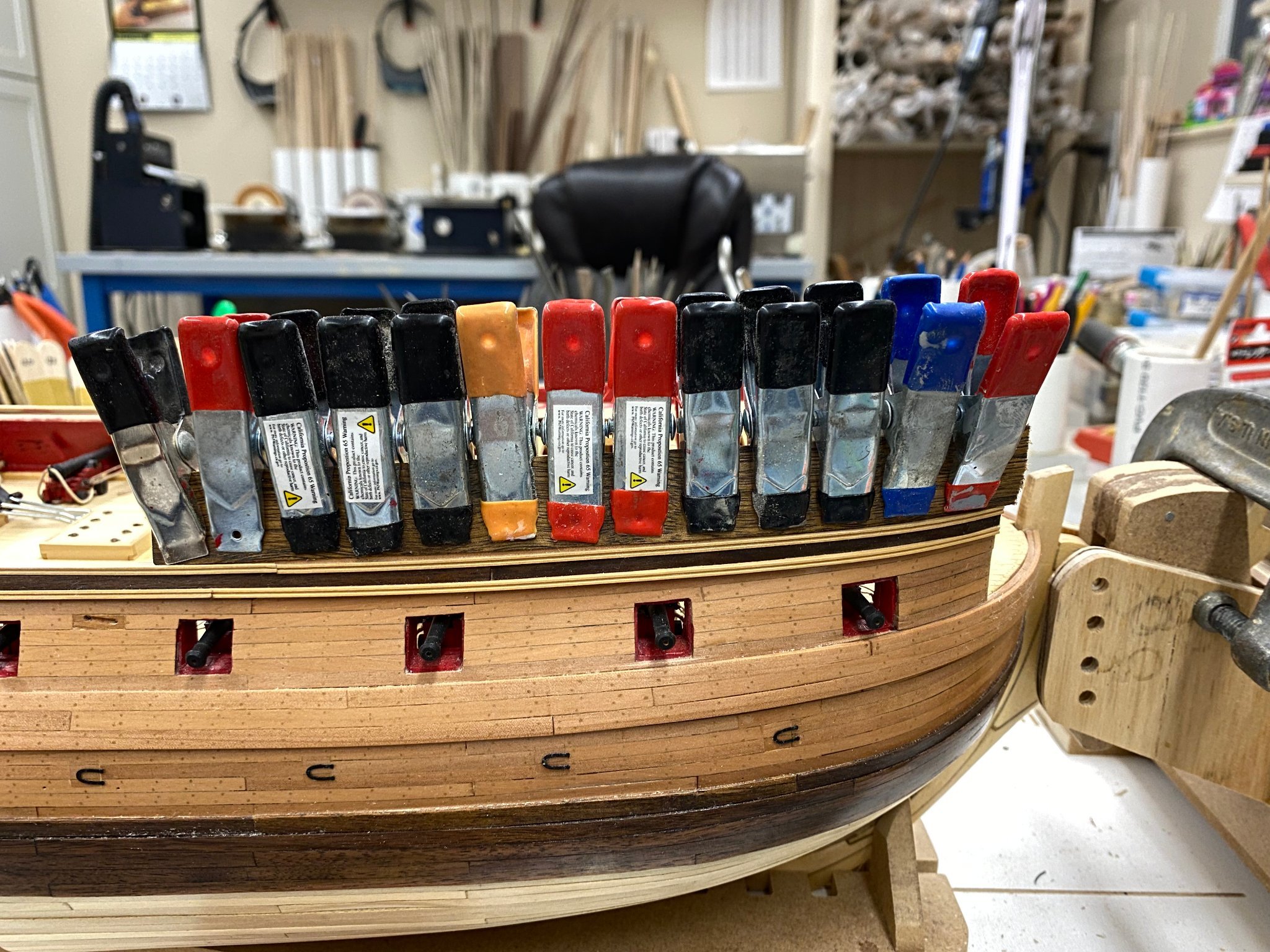
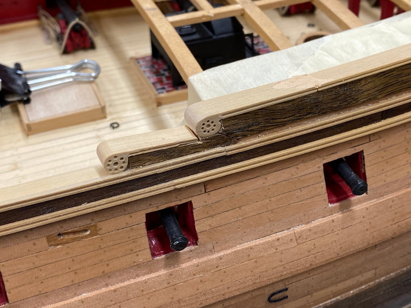
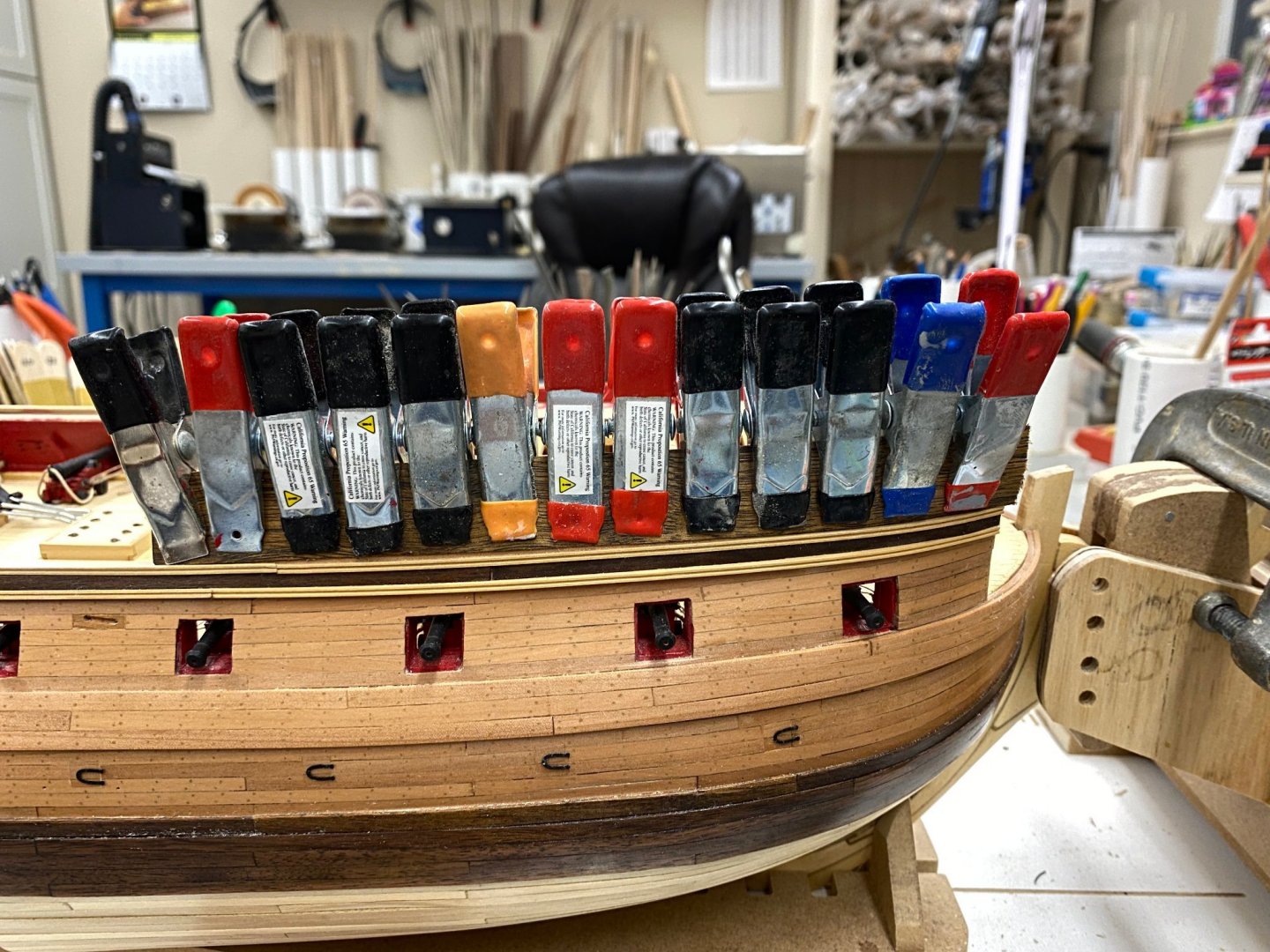
Working the port side aft now because I forgot I needed to add walnut veneer to the forward outer bulwarks instead of painting them black per the instructions. Not sure why I did not do this when I was working the veneer aft but... So here I have the veneer "fully" clamped (I hope) on the starboard side. Need to make sure it is glued up really well, especially at to the top of the bulwarks as trimming it can be a challenge when the wood grain thinks it is in charge. We will see how this works out tomorrow. Did I mention you can never have too clamps? While waiting for that to dry I got the port side quarterdeck railing on. Still need to get the "fitting" in place but here is how it looks now.

- 370 replies
-
- 3
-
-
- Model Shipways
- Confederacy
- (and 1 more)
-
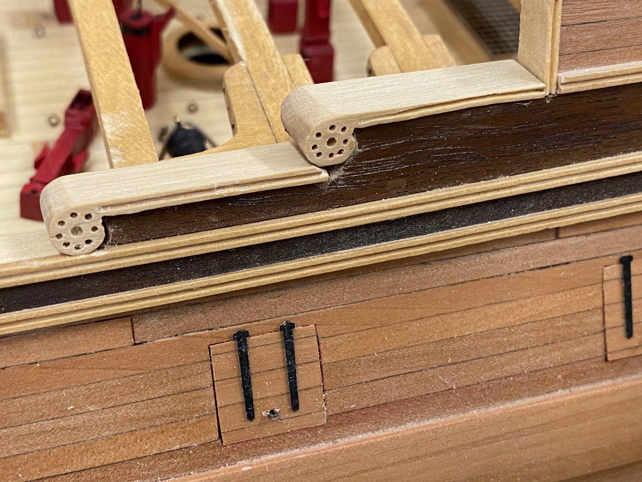
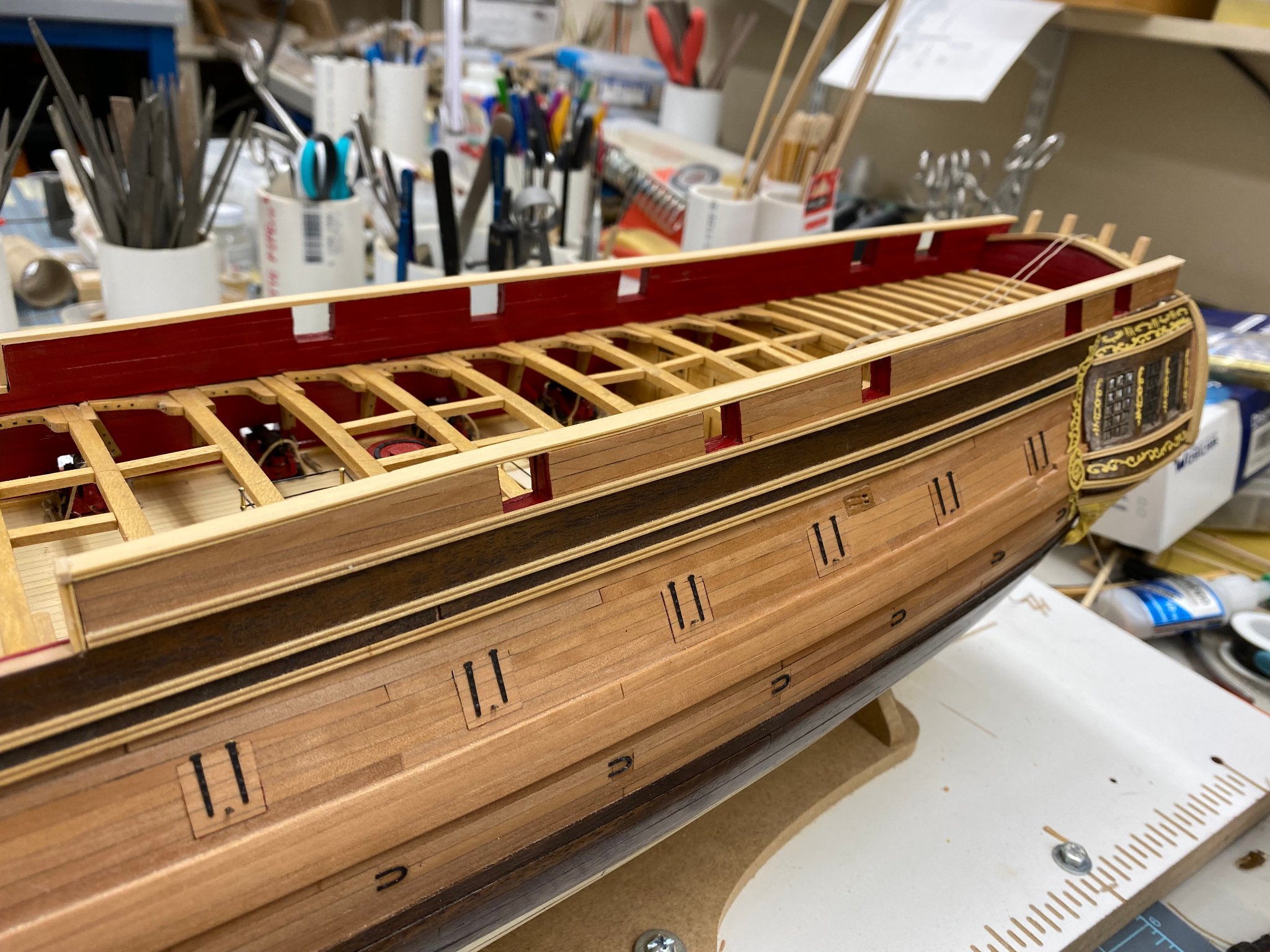
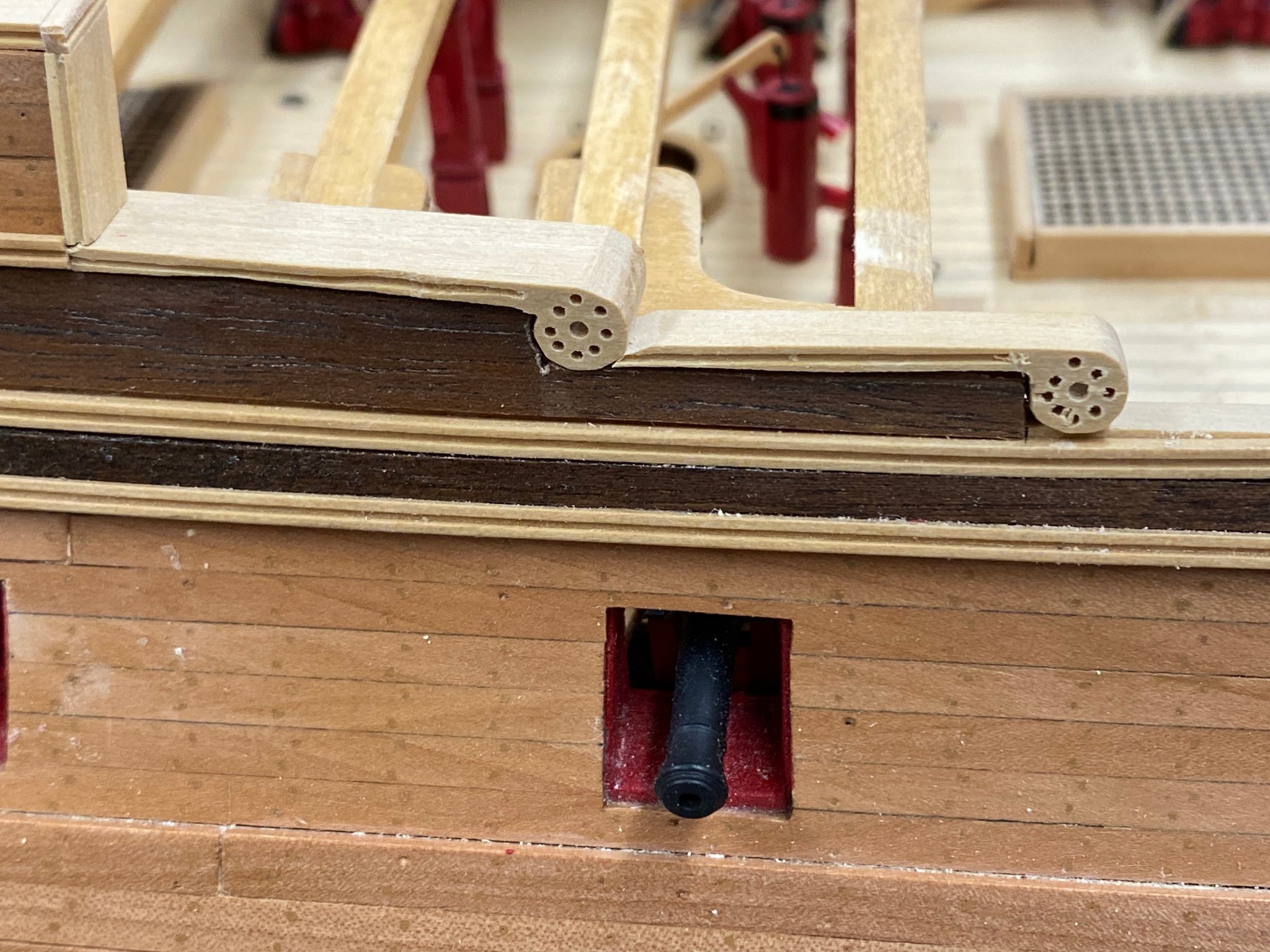
Quarterdeck rail, starboard side is "in". I used 1/4" X 1/16" boxwood material I had left over from something rather than the instructions directed 3/16" X 1/16" because I used the molding cutter to put the double bead on the 1/4" wide material thus no need for the extra step and potential glue getting out of control. I did mount the rail flush with the inside so it sticks out a bit as it would have on using the instructions. I am not sure it sticks out as much as it should as I do not think I got the bulwarks as thin as the instructions indicated. Here is the starboard side. The instructions silent and as best I can tell so are the plans on what to do at the end of the rail where bulwark ends. I continued the rail down the face and then covered the "seam" with a short piece of molding cut into a 1/16" X 1/16" piece of boxwood (which has not been trimmed yet). And now my attempt at replacing the volutes supplied with the kit. I have no hope of reproducing these in boxwood so I made the "fittings" you see here back in May They are not glued in yet, just being dry fit to see if I did not make some grievous error - so far so good. except for that "wobble" in the upper one - I had some trouble with the molding cutter on that one.

- 370 replies
-
- 4
-
-
- Model Shipways
- Confederacy
- (and 1 more)
-
I got all the interior bulwark planking completed and sanded/planed down to match the exterior planking. Now for some touch-up painting (like around the gun ports) and then we can move to the quarterdeck and stern cap rails. Here is the starboard side after the painting. The tape is to keep the paint off the exterior - at least in theory.

- 370 replies
-
- 3
-
-
- Model Shipways
- Confederacy
- (and 1 more)
-
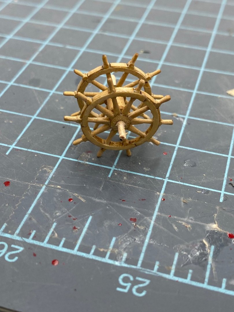
I finished assembling the two 15/16" Syren Ship's wheels, cut the 5/32" dowel for the drum and found two small circular piece for the ends of the drum. After I glued the small pieces on I looked and the instructions show the ends have holes already cut in them. The ones I used did not have the holes. Probably should have stopped there and found the right pieces but... Anyway, I drilled holes AFTER they were securely glued to the drum. Even then I worked up to 1/16" in four steps to keep from tearing the wood. Worked okay but would have been a lot faster if the holes were cut by the laser. I cut some pieces of round toothpick to serve as the shaft and glued that is both ends. I have the supports ready to go but am waiting to paint them when I touch-up the interior bulwarks - any day now. Here is the ship's wheel ready to mount iin the supports.
- 370 replies
-
- 2
-
-
- Model Shipways
- Confederacy
- (and 1 more)
-
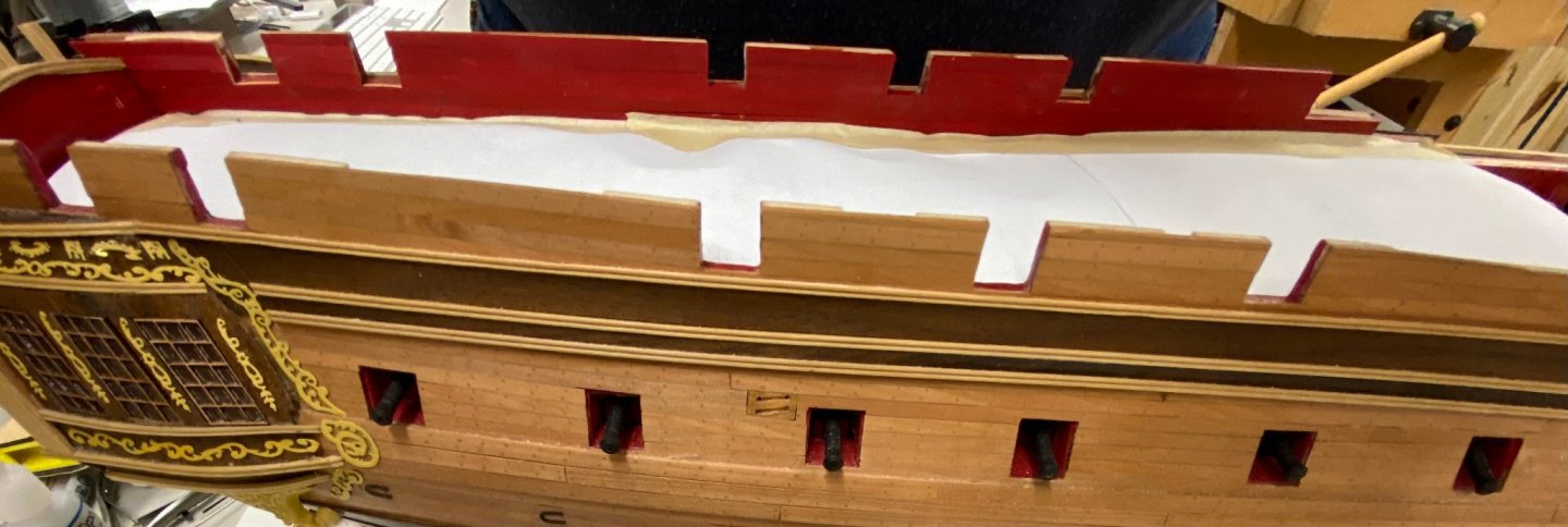
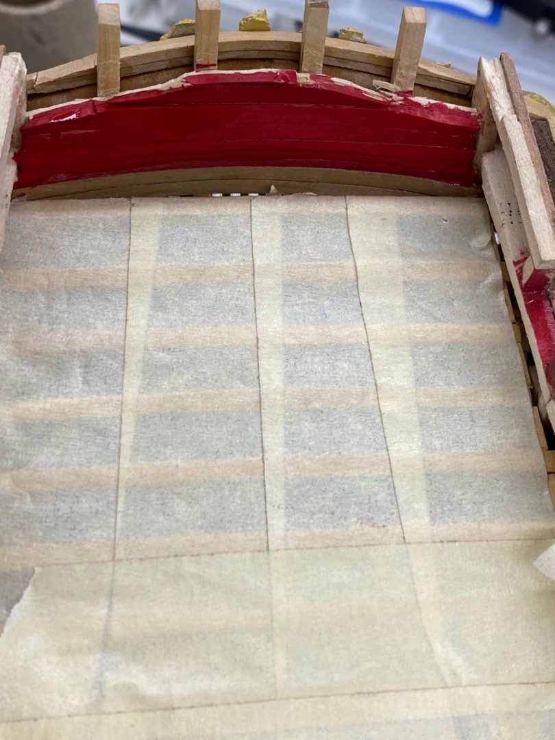
I cleaned up my "lower stern rail" and put a coat of clear satin poly on. Looks better but I still need to touch up the red paint. Waiting until I have all the inner bulwarks planked so I can get all the red touch up done at once. I got the bulwarks on the port side planked and have turned the model around on the workbench to work the starboard side. That is why the paper is not taped down on that side yet. Here is the port side planked but not yet touched up.

- 370 replies
-
- 2
-
-
- Model Shipways
- Confederacy
- (and 1 more)
-
Back on the model itself I got my "five piece band" of fillers in place between the stern timbers but decided that the "seams" were too unsightly. I took the same piece of boxwood that I made the filler pieces from and thickness sanded it down to a lttle less than 1/64" thick and cut a piece to run in front of the stern timbers and then added a piece of fancy molding to cover the seams from the front. So here is the stern transom prior to light sanding and coat of W-o-P. Clearly some touch-up on the planking is required.
- 370 replies
-
- 2
-
-
- Model Shipways
- Confederacy
- (and 1 more)
-
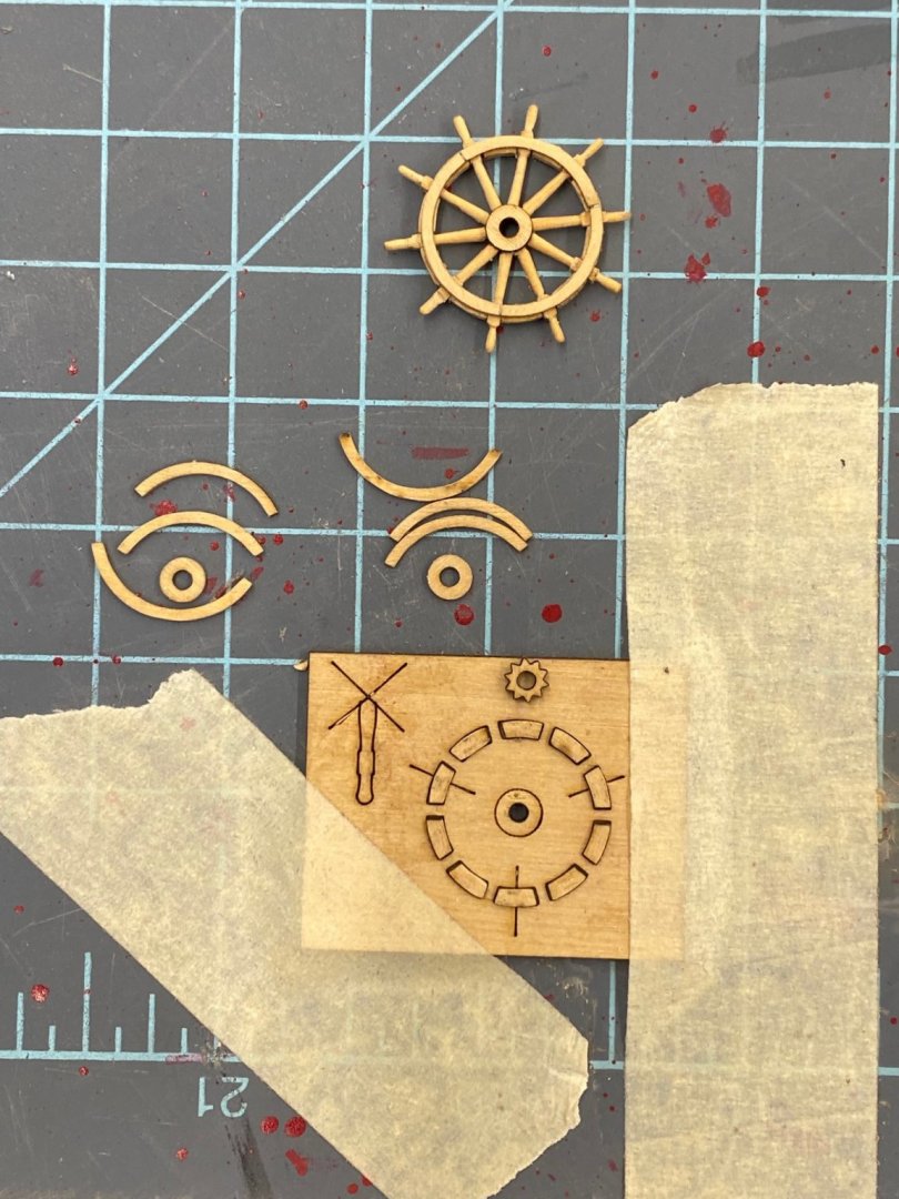
I am not a big fan of Britannia metal fittings in general so when I saw that the ship's wheels (there are two mounted on a common shaft/drum on Confederacy) were of this material I started looking for something else. The ones that came with the kit measure .83" in diameter at the ends of the hand grips (or approx 21mm for those so inclined). Most of the non-metal pre-made wheels on the market appear to be somewhat out of scale (too thick) and either considerably bigger or smaller although I admit to not having done an exhaustive search. I have, in the past used the kit-made wooden ship's wheels from Syren Ship Model so decided to give that a go here. Unfortunately the smaller of the two wheels on offer is 15/16" in diameter (24mm) or about 15% bigger than the kit provided. I looked at the mounting system for the wheel assembly and may have to add some pads for the wheel supports to get enough clearance above the deck but think that is a reasonable trade-off for the better looking wheel up on top of the quarterdeck in plain sight of even a casual observer. Here is one completed wheel (unfinished) and the pieces of the second one in the jig provided. Other than having to sand the laser char off some pretty small and delicate pieces assembly is pretty straightforward (assuming you have a Dremel or similar tool for turning the spindles) and the site has a good set of instructions available for download. Although not mentioned in the instructions I found it helpful to tape the jig down - one less thing to move around as you try and get the pieces in the jig to stay put as you glue the rim pieces in place.
- 370 replies
-
- 2
-
-
- Model Shipways
- Confederacy
- (and 1 more)
-
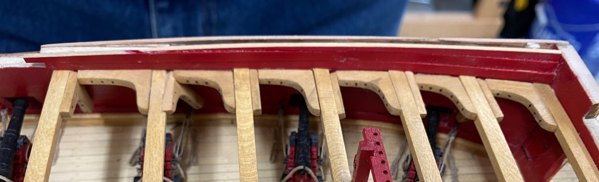
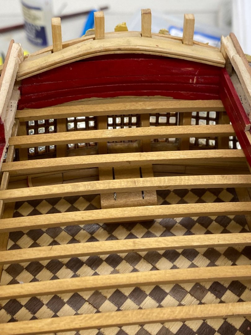
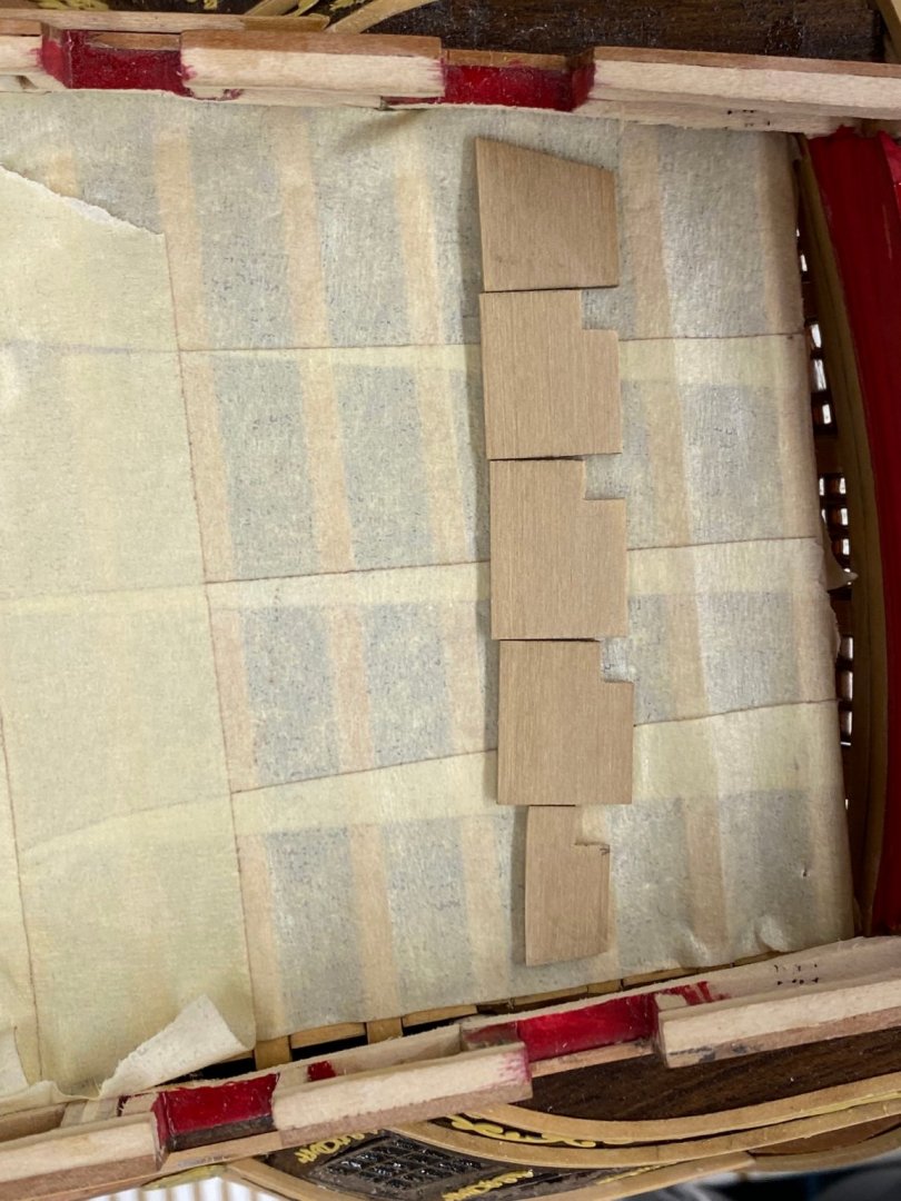
So having finished up (for now) the knees (and beams) the next step is to finish planking the interior of the bulwarks. So I decided to start on the interior of the transom. Try as I might I was unable to get a "reading" on what (if anything) fills in the gap between the rail that crosses over the top of the stern non the outside (that has all the figures sticking above it (a bit) and the interior planking. The stern rail runs over the top of the extended stern timbers (now box wood on this model). And when I started adding the interior planking I noticed that at least on my model it was not going to be easy to get the planking all the way back to the stern timbers without a lot of struggle. To make a long story short (ish) I decided to fit a boxwood "cap" to span between the inboard edge of the existing stern rail and extending inboard to cover the edge of the interior planking (and the gap that mine seem to have. I looked at the layout and decided that trying to cut a single piece was probably a bad idea since it needs to notch around the stern timbers and is curved to boot. I decided to cut it in five pieces since it will be hidden a bit by the stern rail that goes on top of the stern timbers. Here is the stern showing the existing rail over the figures. This is the somewhat butchered up stern planking after the first coat of paint. The masking tape is to protect the Great cabin and deck beams from paint and debris. When I started adding the planking I was unsure how far to go and ended up going further than I would need with the extra rail so I had to take some out. Next time I'll try and be more sparing with the glue. Luckily this will all mostly be hidden from view. And here is my "five piece band" of filler pieces - only one has been trimmed to the correct width. If I can get the inboard edge to cooperate I may add a piece of the double bead molding to the interior edge just because I think I can.
- 370 replies
-
- 2
-
-
- Model Shipways
- Confederacy
- (and 1 more)
-
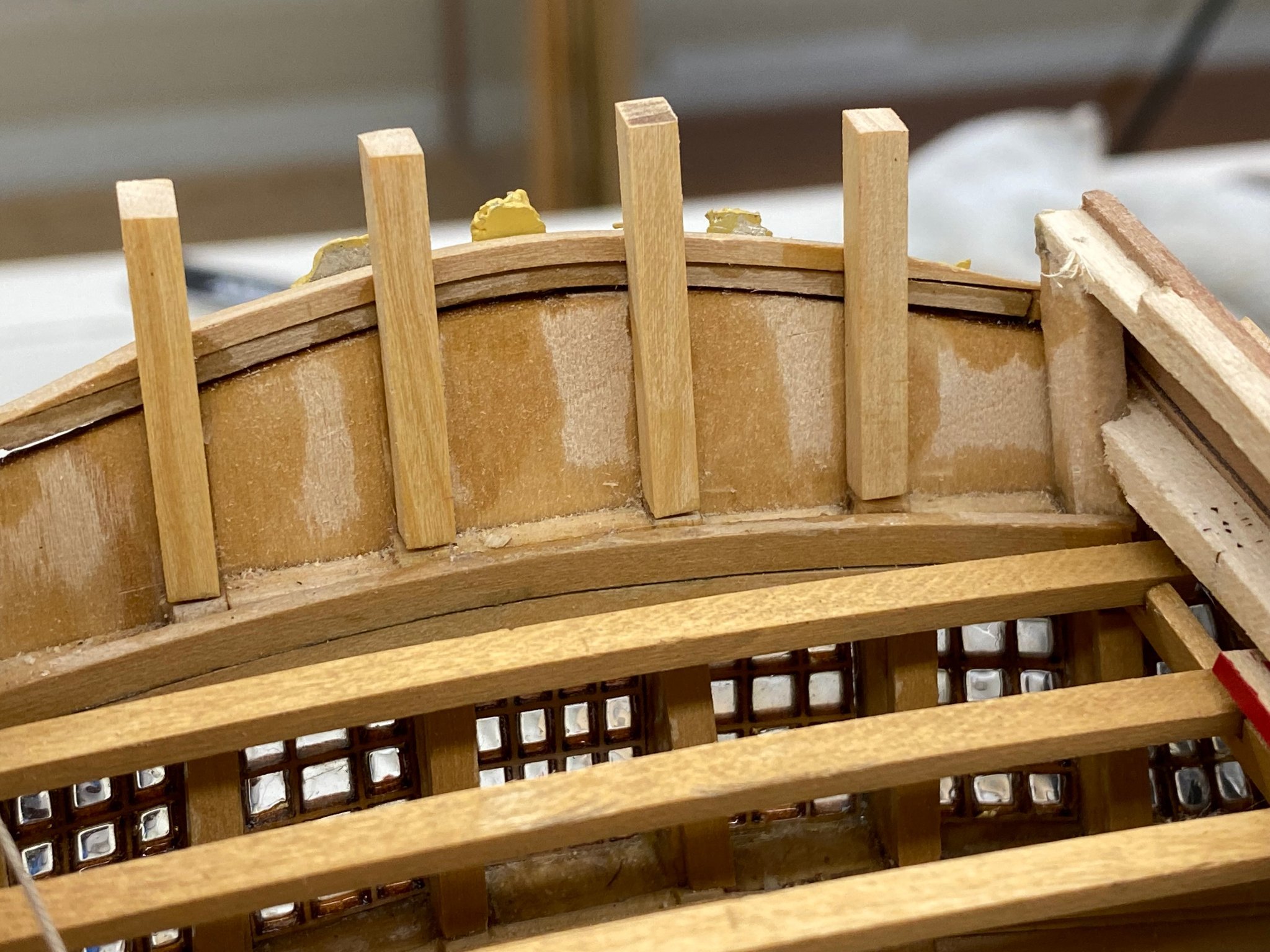
Completed (I think) the deck beams and carlings at the bow. Interesting is that while the instructions do not mention, nor the pictures show, the drawing shows carlings between the third and fourth beams (where the bitts are). I may actually install something for a landing for the decking in front of the bitts for as it stands now they would just "hang" there. Anyway here is the forward area as it stands now. Since (pending more carlings forward) the next step is to finish planking the bulwarks I have another task to do before that. I want to depart from the kit material and finish and do the quarterdeck rail in boxwood instead of painting it black and leave the exterior bulwark in the Swiss pear. So, I decided to replace the current basswood stern timbers with boxwood ones. I was worried about tearing up the stern but I apparently was careful with the glue and was able to carefully cut the existing timbers out where they meet the deck. I (hopefully) was able to get the spacing and height per what was there. Here is the stern with the boxwood timbers. Next step is to plank this part of the stern.


- 370 replies
-
- 4
-
-
- Model Shipways
- Confederacy
- (and 1 more)
-
Thank Bruce - I am still at a loss for how this happened. The pictures I took back when installing the deck furniture and coamings do not make it obvious that anything is amiss or I likely would have noticed before now. Your are correct, anyone who looks at the Fore Topsail bitts and the hatch between will wonder why the hatch is not centered. Onward, but I will take extra care next time making SURE I know where the centerline is when installing the coamings and such.
-
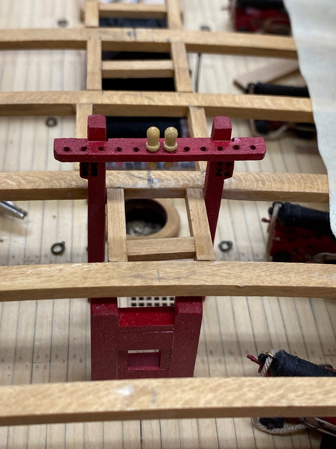
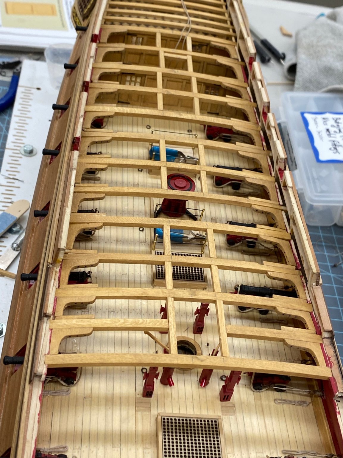
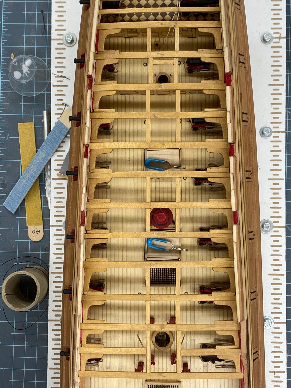
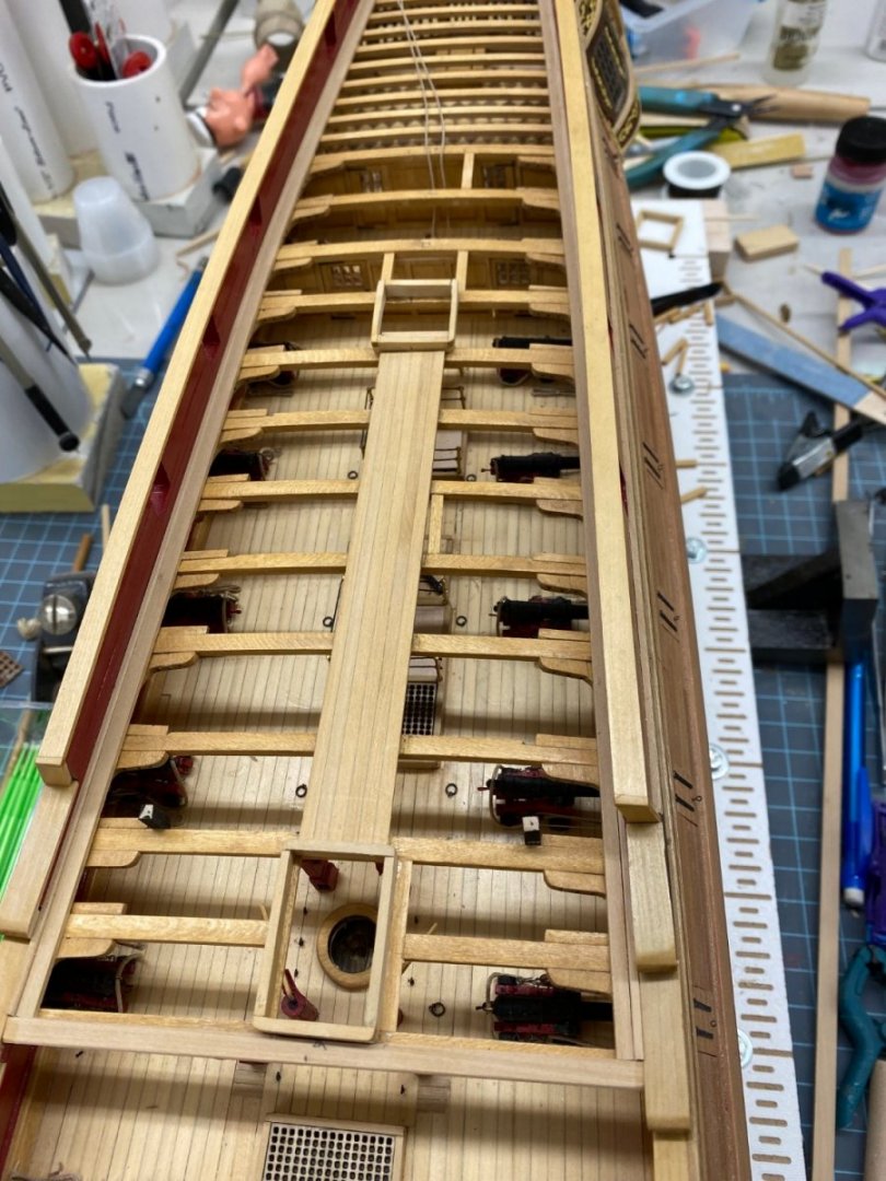
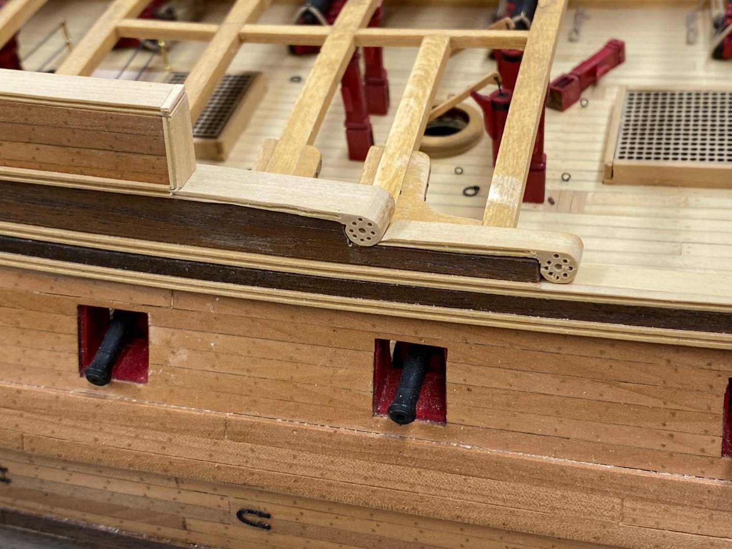
Getting close to finishing the deck beams and related knees. I completed the first four deck beams forward and built and installed the Fore Topsail Sheet bitts. No real issues except I added a .025" phosphor bronze pin to hold the pin rail to the bitts. Probably not needed in this case since the pin rail and belaying pins are purely ornamental but it is a lesson I learned some time ago when the pin rail came off the bitts when I was tensioning a piece of rigging. Not a good time to try and repair something like that so I almost always use pins in addition to glue. So here is the forecastle - easy to see that I got the forward most hatch in a good bit off center. FYI my review of the pictures did not produce any more info on how I managed to get that far off but...

- 370 replies
-
- 4
-
-
- Model Shipways
- Confederacy
- (and 1 more)
-
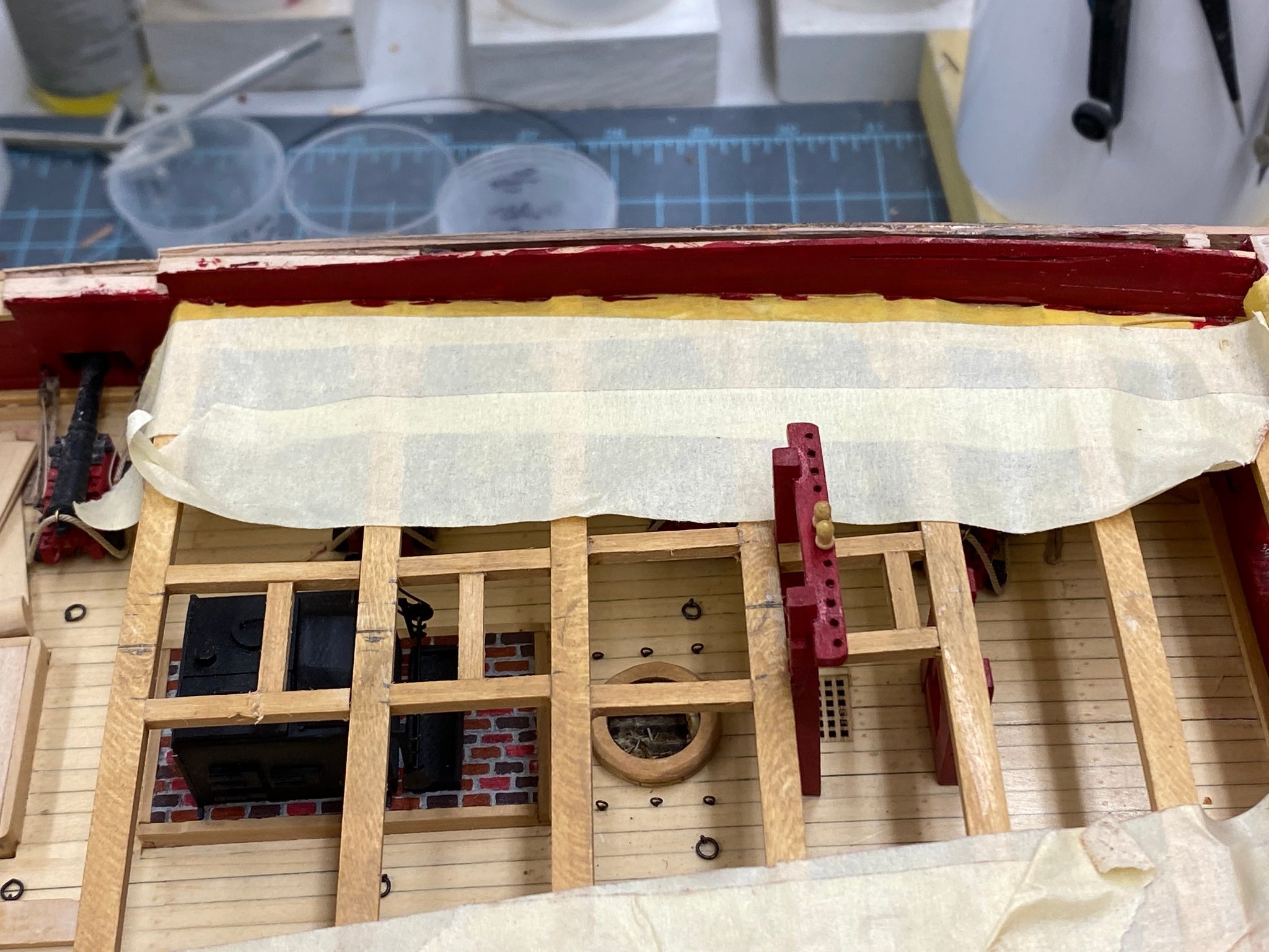
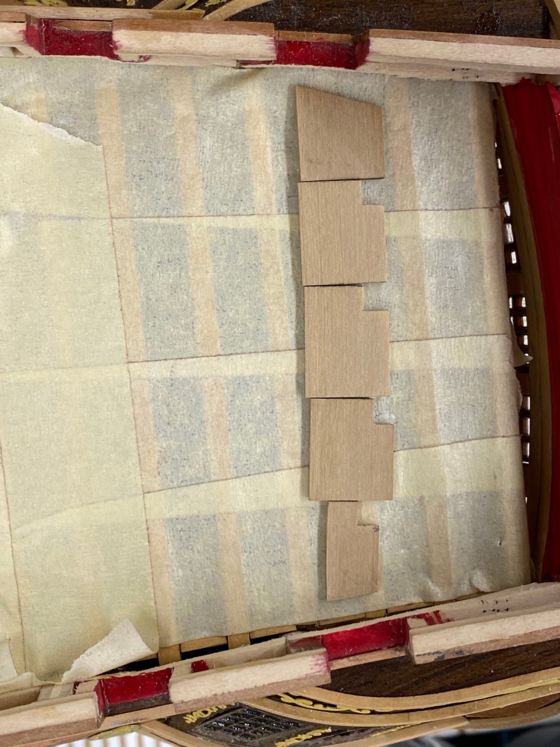
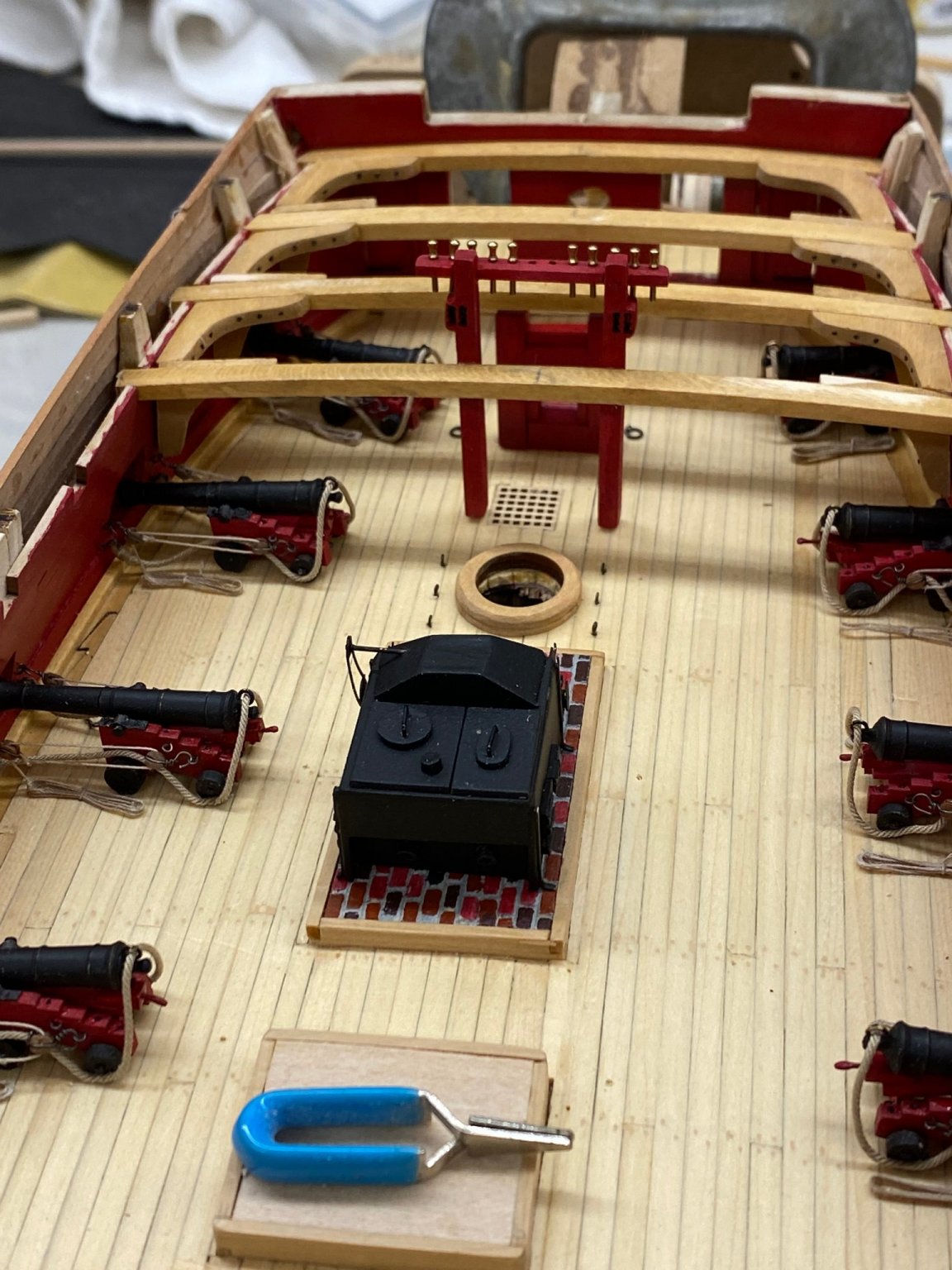
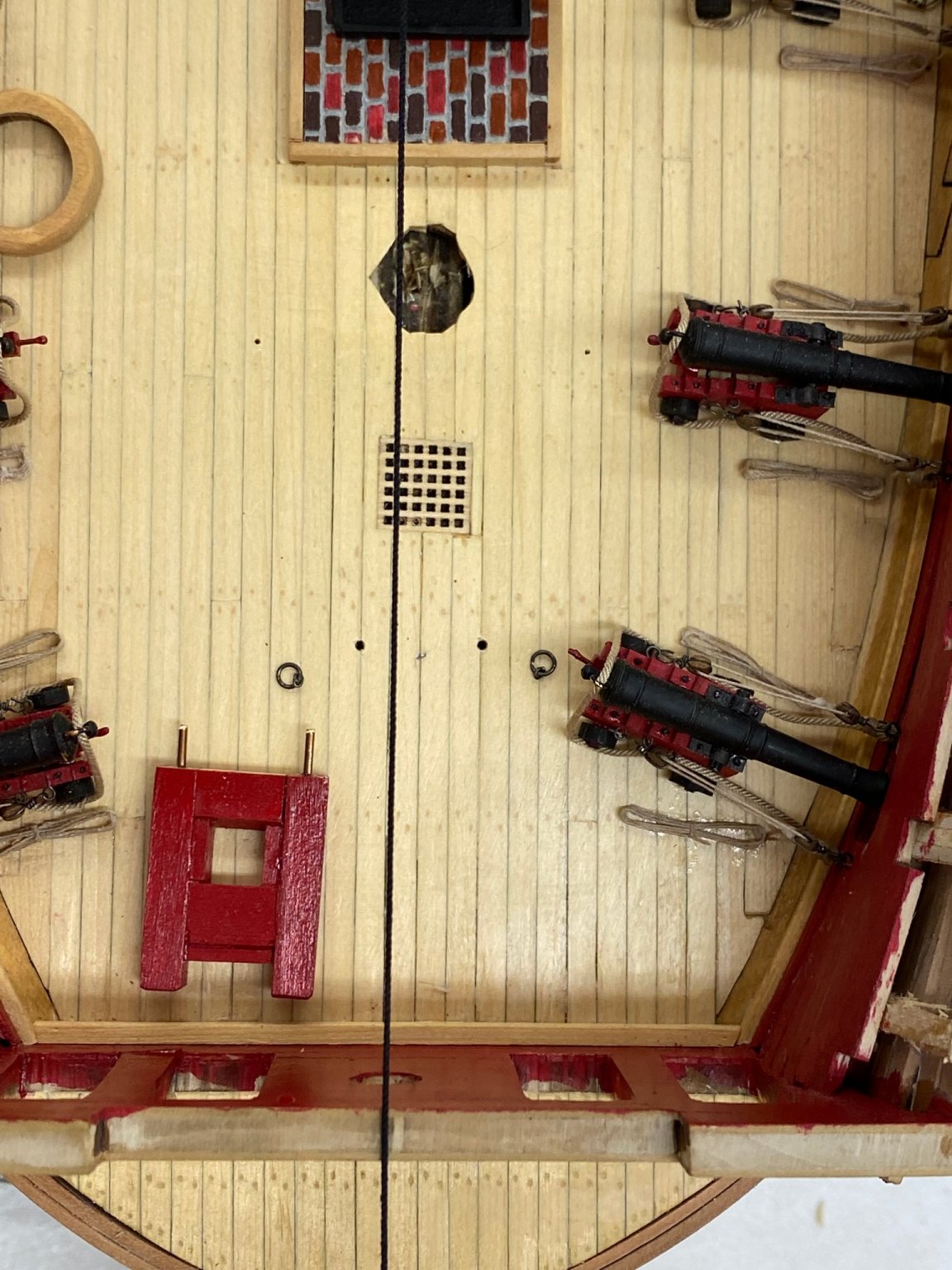
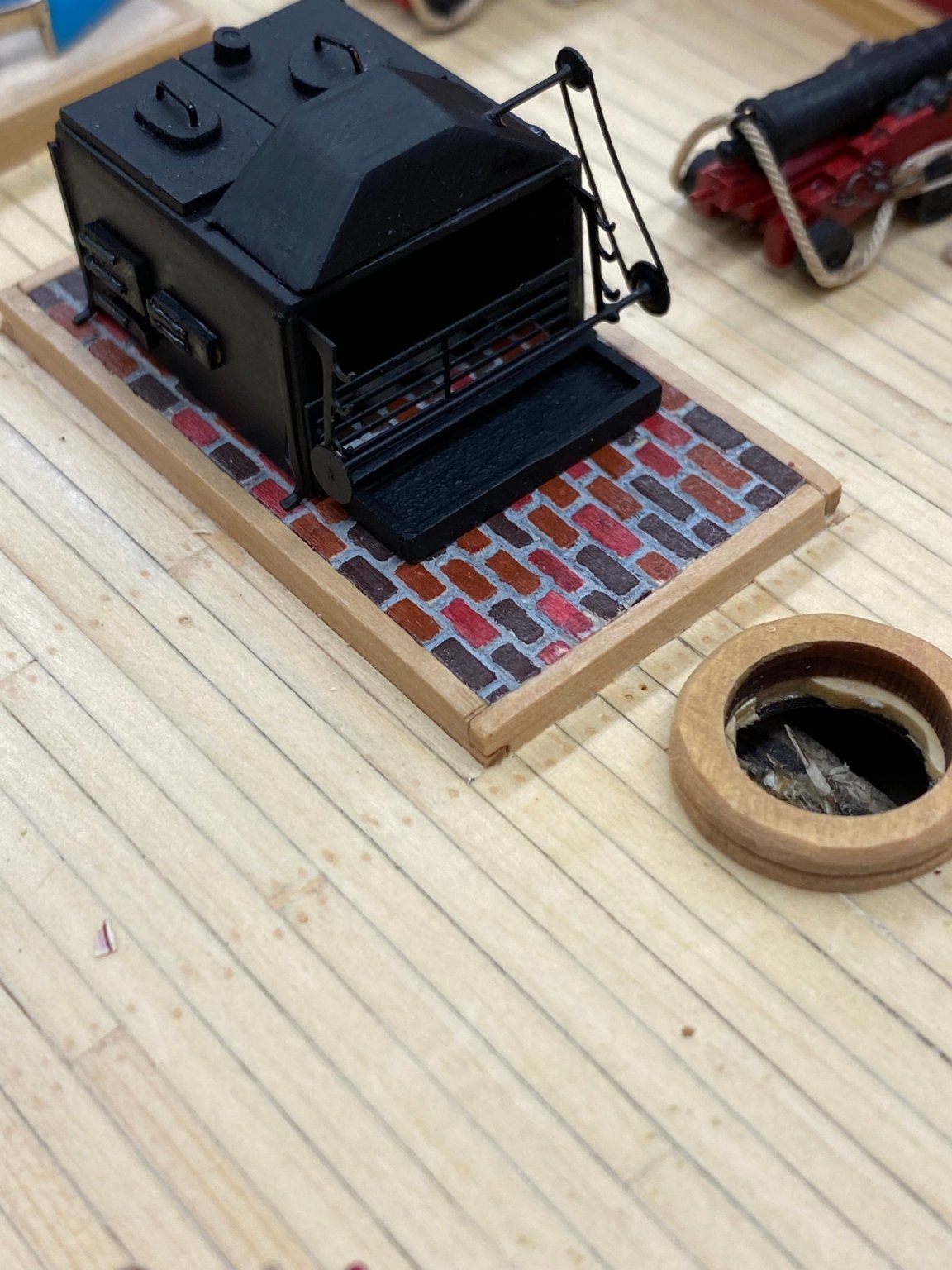
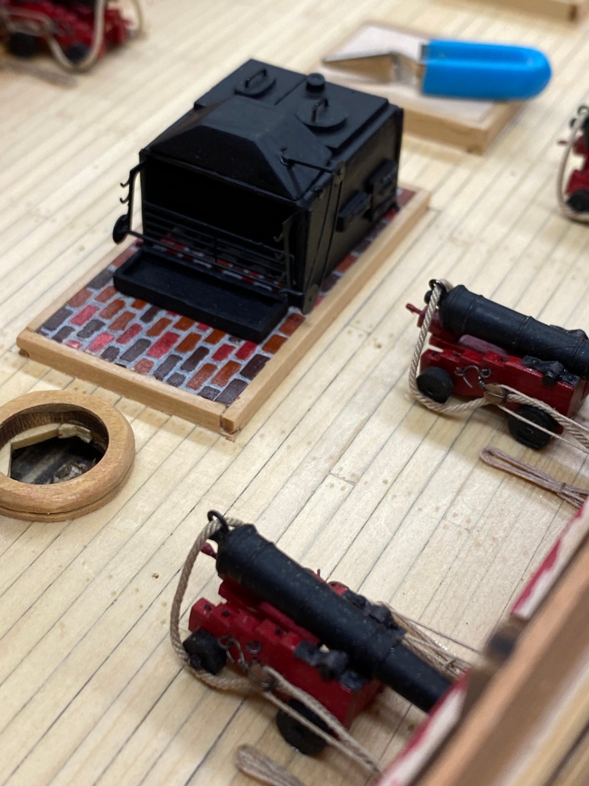
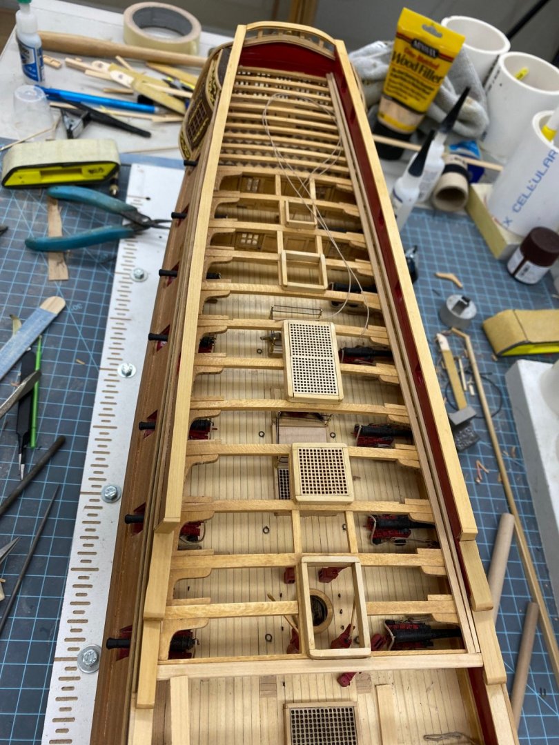
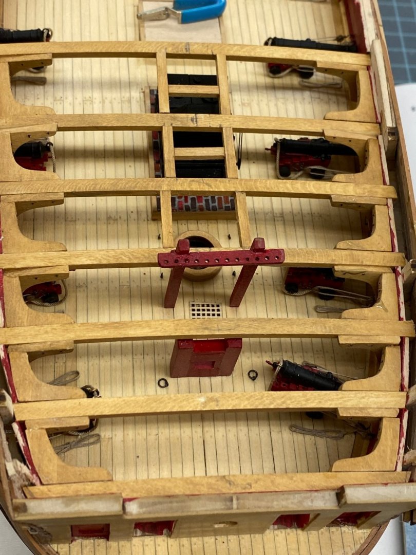
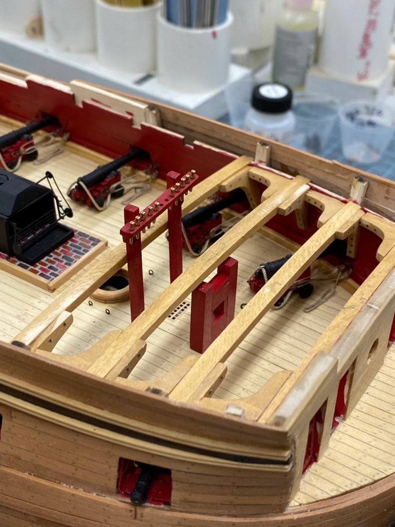
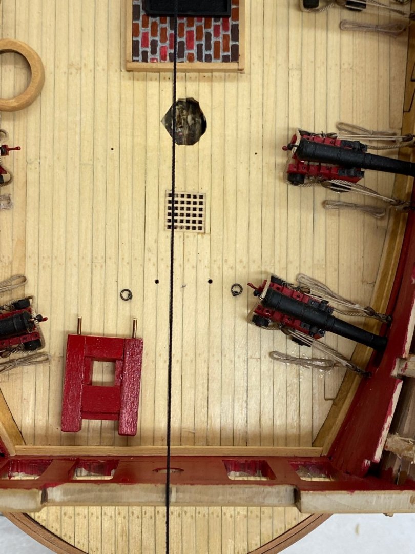
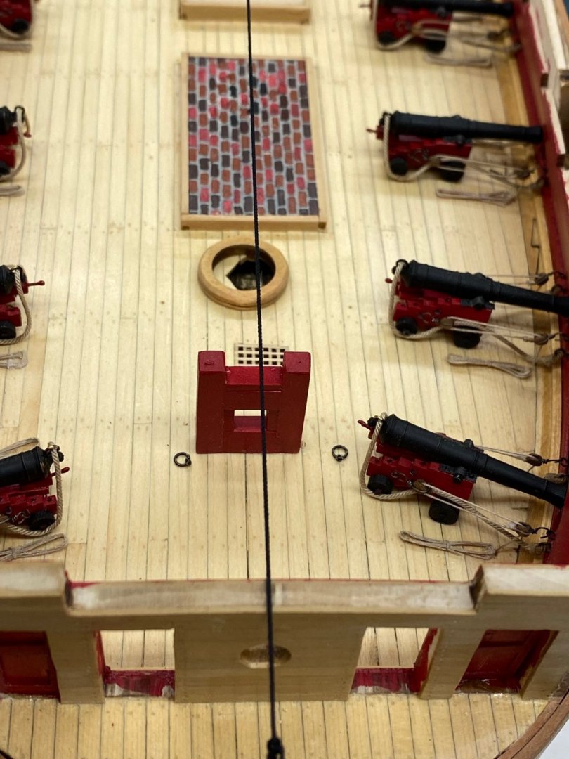
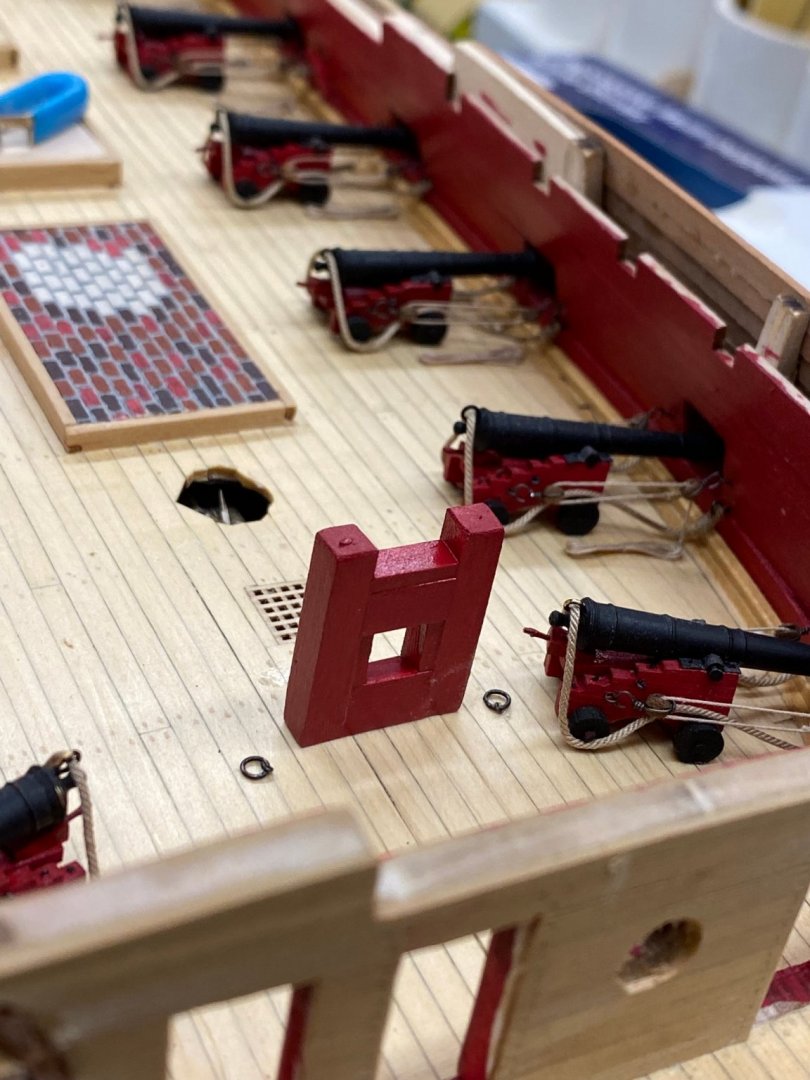
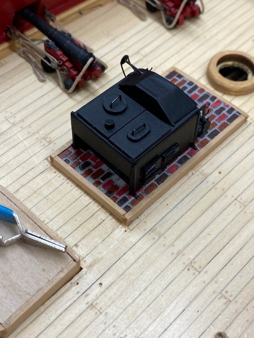
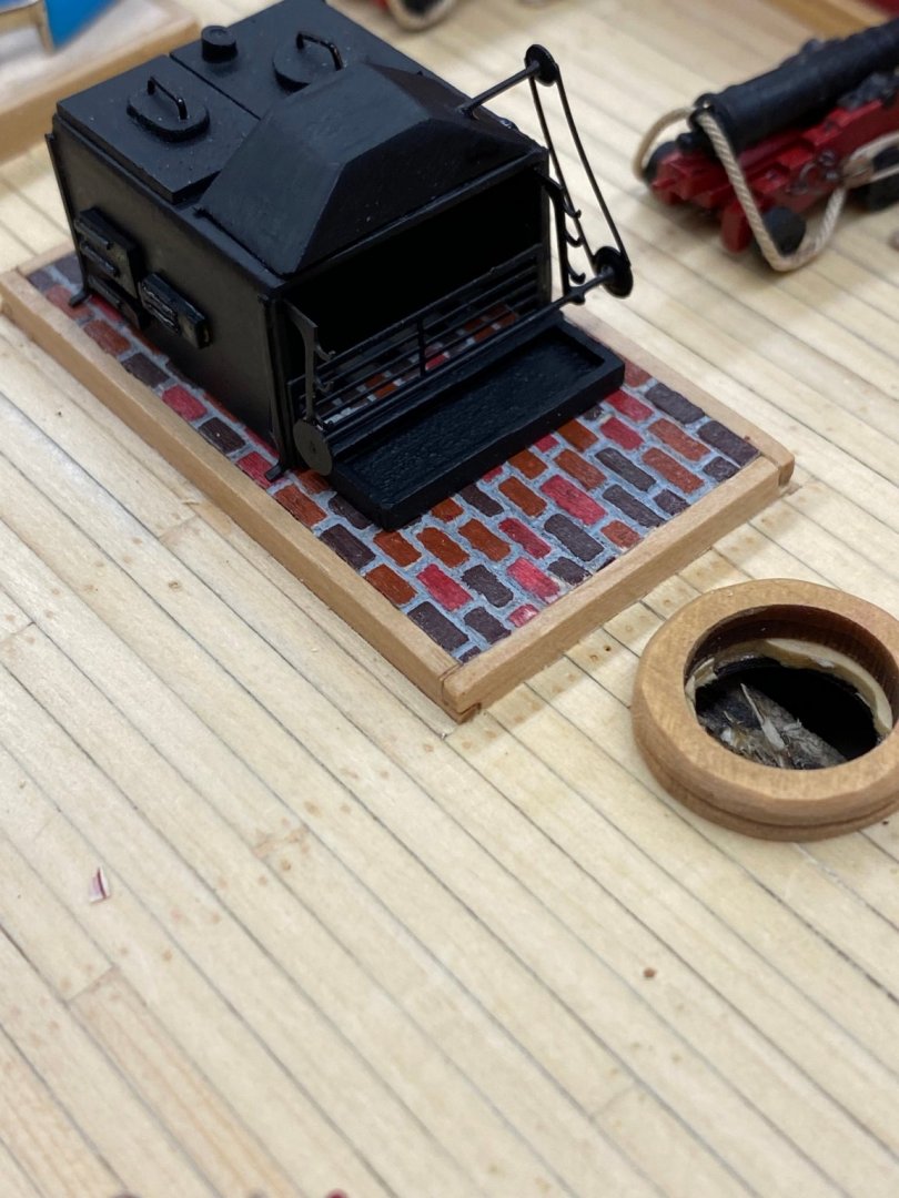
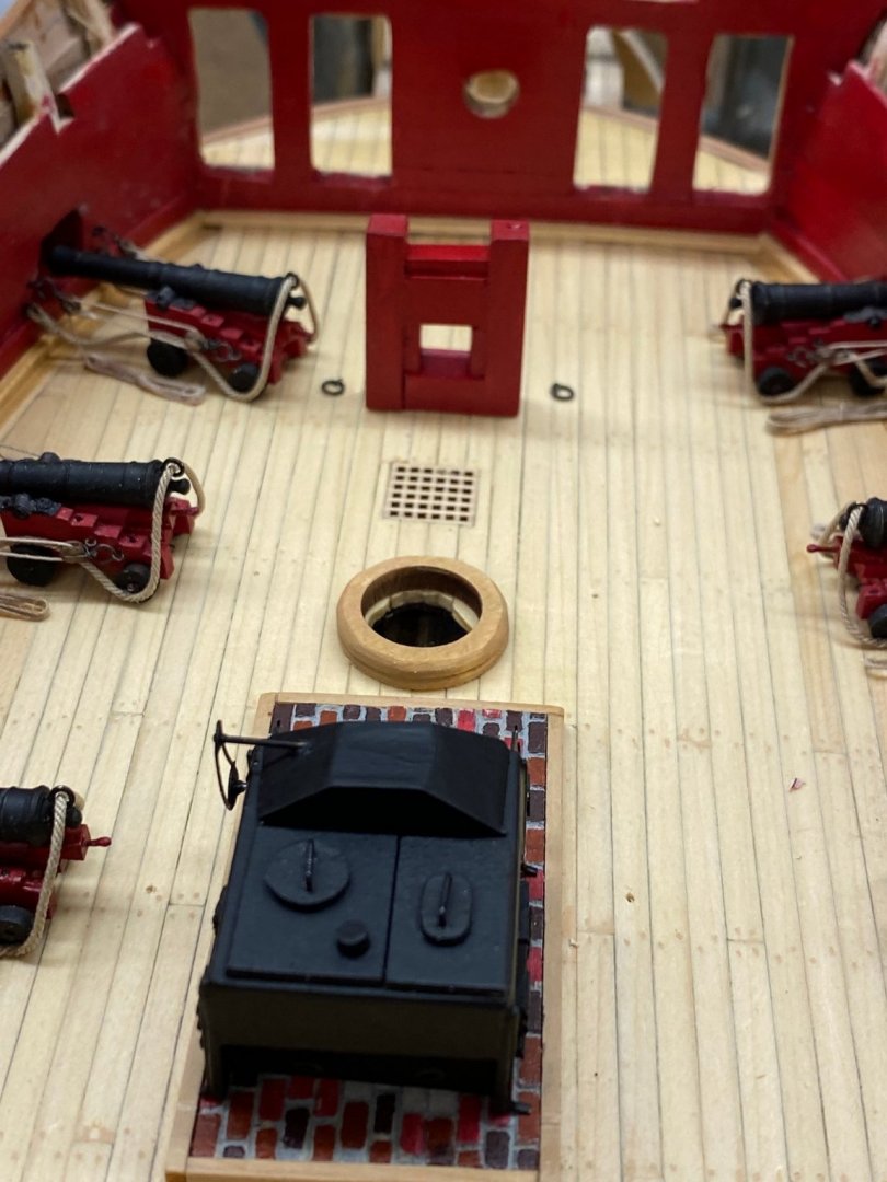
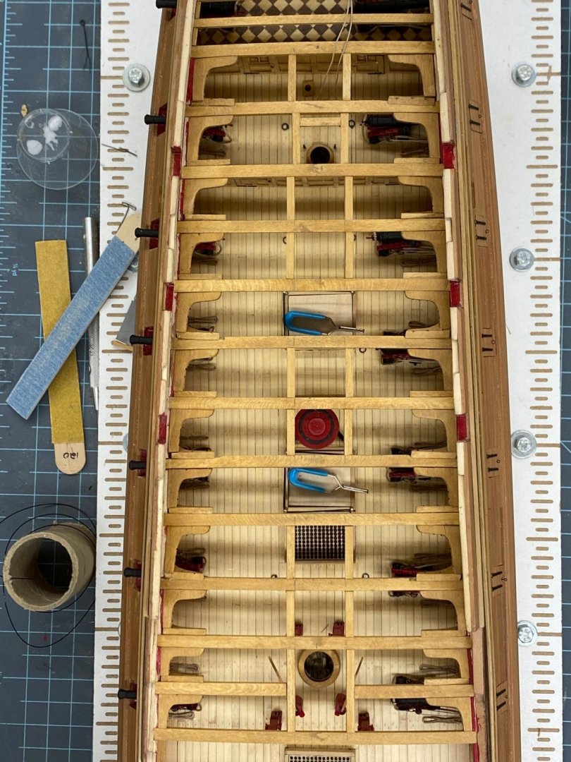
It has been one of those days - my work laptop froze trying to install the latest MacOS upgrade and it appears I somehow got the forward part of the model out-of-center. On the model it started when I looked at the bowsprit bitts and the hole in the beakhead bulkhead when the bowsprit will fit. The two opening did not line up correctly. I took the hole in the beakhead to be "ground truth" as it appears to be directly behind the stem. I took a piece of line and looped it over the stem and ran it over the stern at what looks to be the center then looked down on the bow area. Based on this evidence (I tried my best to get the camera lease dead center over the line but...) it appears that I have the holes for the bowsprit bitts, the foremast and the hatch one plank too far to port. Not sure how I managed to do that but that appears to be what I did. Luckily, further aft at the main and mizzen the mast coats are centered under the line so what ever I did I apparently corrected it in the after portions of the deck. I am going to go back and look at the pictures I have and see if I can find the error but I will not spend too much time on that effort as I have a model to build. Since there was a false deck with all the locations for the structures marked I must have grievously misplaced the forward half somehow. Hard to be;lieve I could have been of an 1/8" but apparently I was/am. So I "fixed" the bowsprit bitts location and will adjust the hole for the fore mast. It looks like the mast coat will "cover" what needs to be done. It will be hard to notice I think since the guns are in different locations on each side and the beams, decking and boats stored will make itb really hard to see that the stove is a bit too far to starboard. Hopefully this is the last "unpleasant surprise" coming my way. FYI, after looking at the stove in place I went ahead and painted the rest of the bricks.
- 370 replies
-
- 3
-
-
- Model Shipways
- Confederacy
- (and 1 more)
-
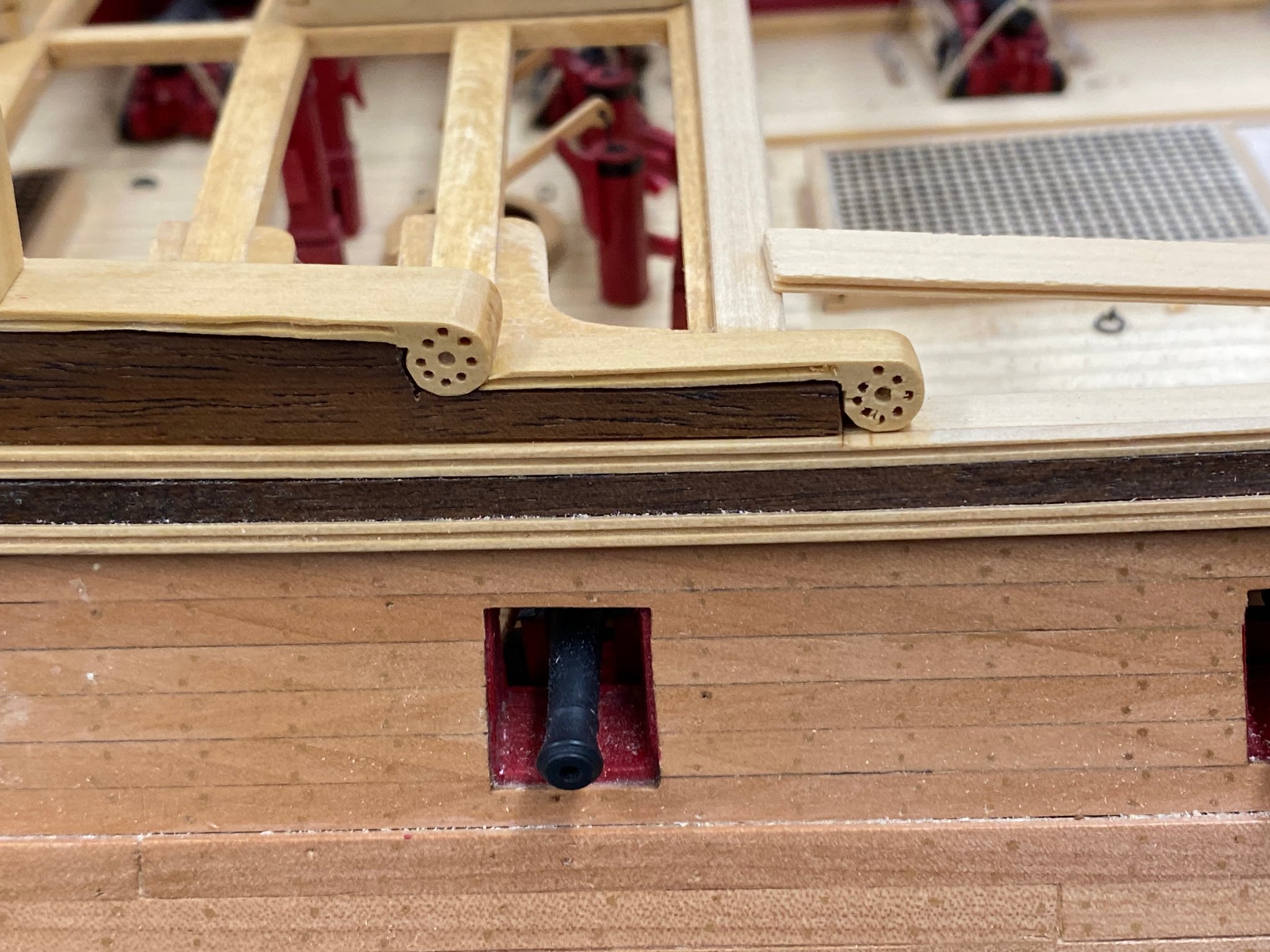
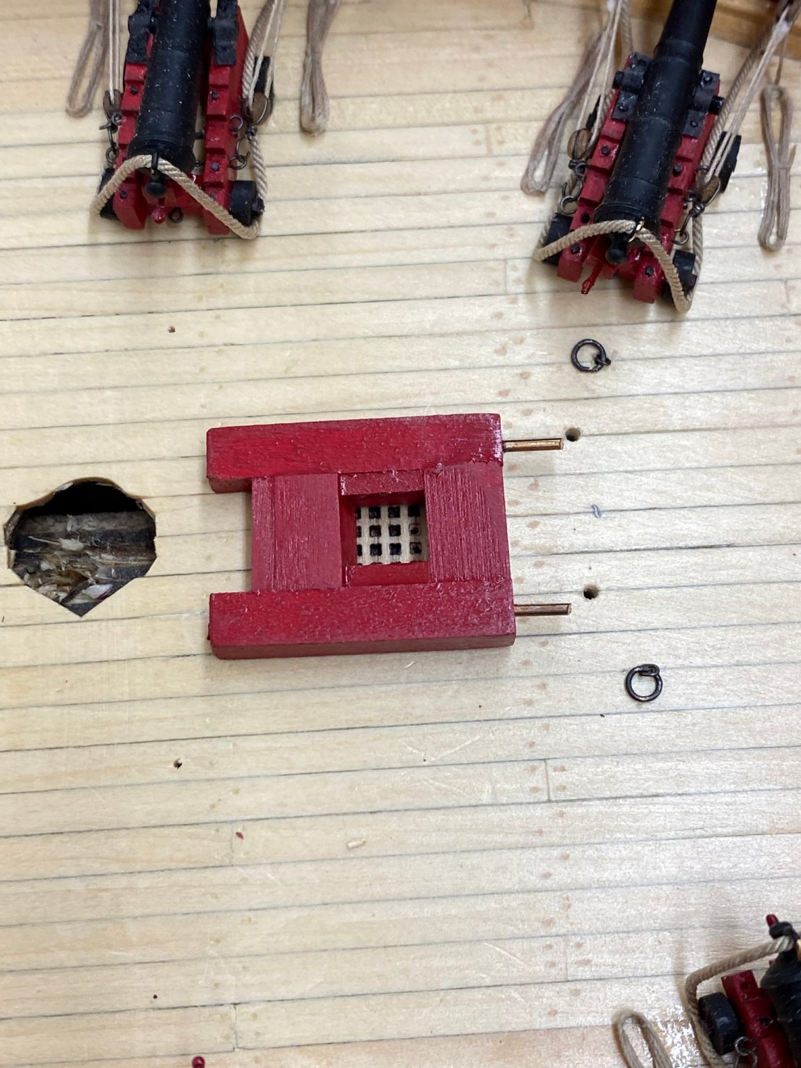
Working from the bow aft now. I have assembled, thinned, painted and fit the outboard set of doors in the beakhead bulkhead. The instructions show painting both sides of the door even though the outboard side will be completely hidden by the "roundhouses (aka "seats of ease"). I decided this gives the option of which side to show if I mess one up gluing on the hinges and door knob. While those are drying from the final (hopefully) coat of paint I assembled the bowsprit bitt. I am not sure how I would have done this without the disk sander. As explained in the instructions the trick is to get the top and bottom of the opening sloped at what I think is approx 15 degrees. I used one piece cut in two for the upper and lower pieces with the "bevel" so I was sure they had the same slope (even if it is not exactly 15 degrees at least they are the same) on both top and bottom. I did as the instructions said and put pins in the bottom to help locate and support the bowsprit bitt. And here it is both showing the pins and receiving holes and installed (but not glued yet). I will glue it down after the doors are installed. With that completed I decided to finish the stove since that will be next after some more deck beams and knees. I had previously (I thought) gotten everything but the rotisserie installed. I found however, that there are three doors (and five hinges) on each side that I had over looked somehow (probably just tired of stove building at some point). Anyway I found the pieces and glued them on. I also got all the pieces of the rotisserie glued on and then painted everything one last time (hopefully). Here is the stove sitting on its foundation while the paint dries. The observant will notice that I have the "drive" mechanism on the port side of the stove - the instructions show it on the starboard side. I am assuming the cook's assistant is left handed. Actually in my haste I glued the shaft and the "drive" mechanism together before I realized that "it matters" which way they go together if you want it to look like the instructions. I was too lazy to fix the problem (even though there are several spare pieces on the photo etch sheet) so I put it on the other side. Looks okay to me - but then I am the captain so my opinion is the only one that COUNTS!


- 370 replies
-
- 4
-
-
- Model Shipways
- Confederacy
- (and 1 more)
-
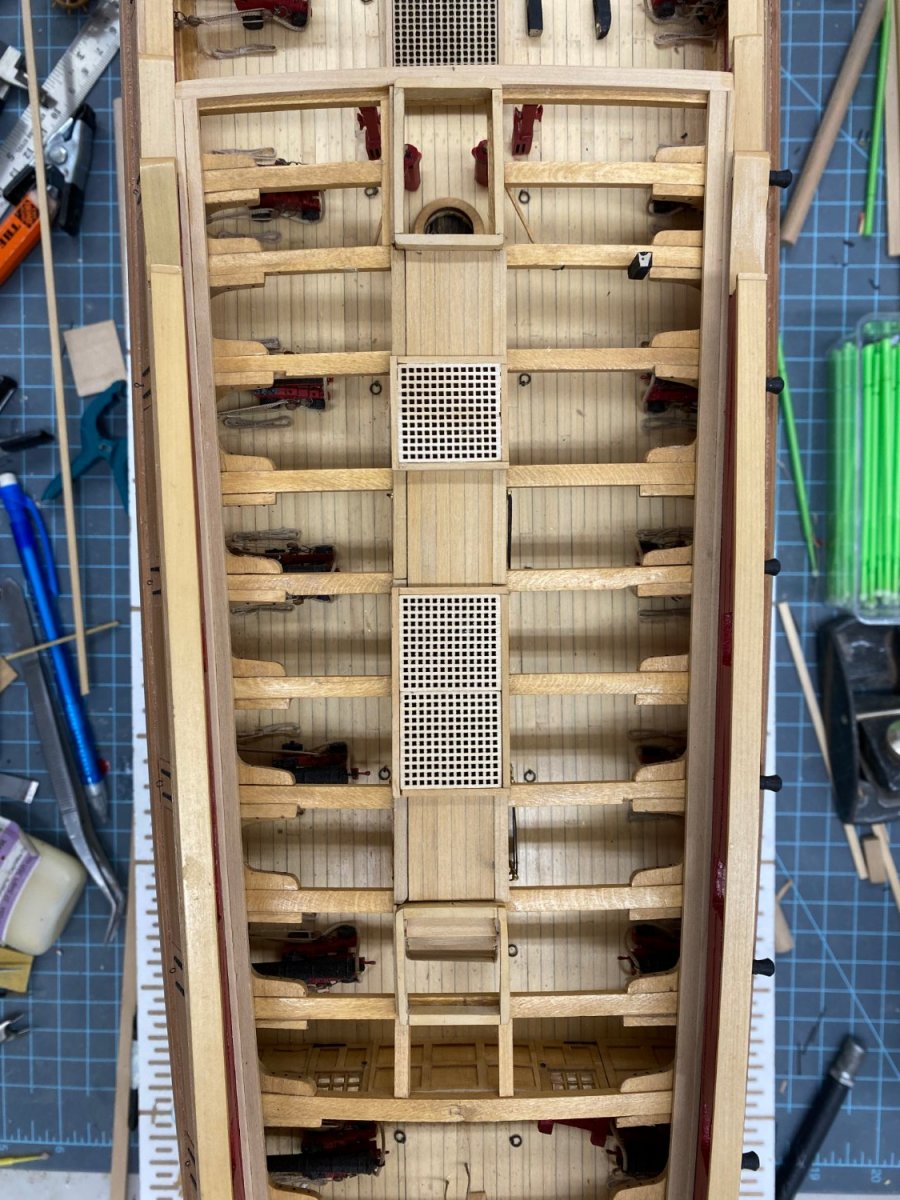
Got the last on the knees installed and according to the instructions "This will complete the quarter deck framing and the fittings below it." Nuff said.

- 370 replies
-
- 5
-
-
- Model Shipways
- Confederacy
- (and 1 more)