cdrusn89
-
Posts
1,923 -
Joined
-
Last visited
Content Type
Profiles
Forums
Gallery
Events
Everything posted by cdrusn89
-
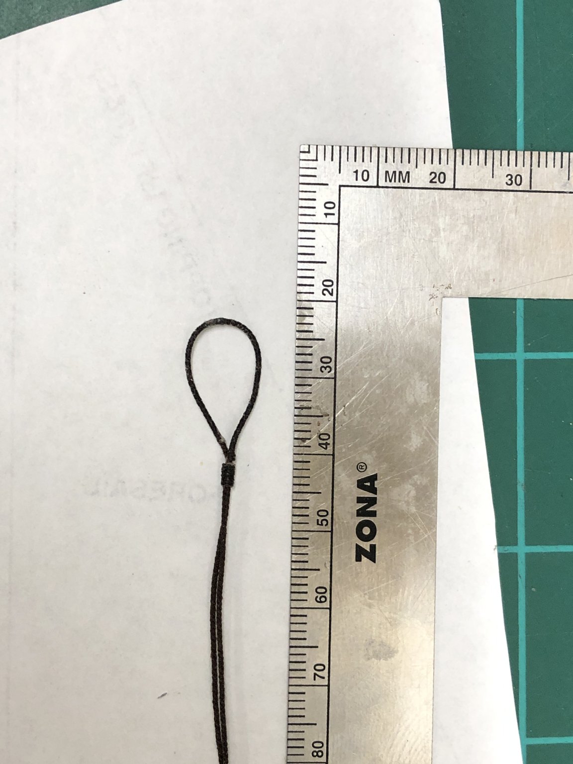
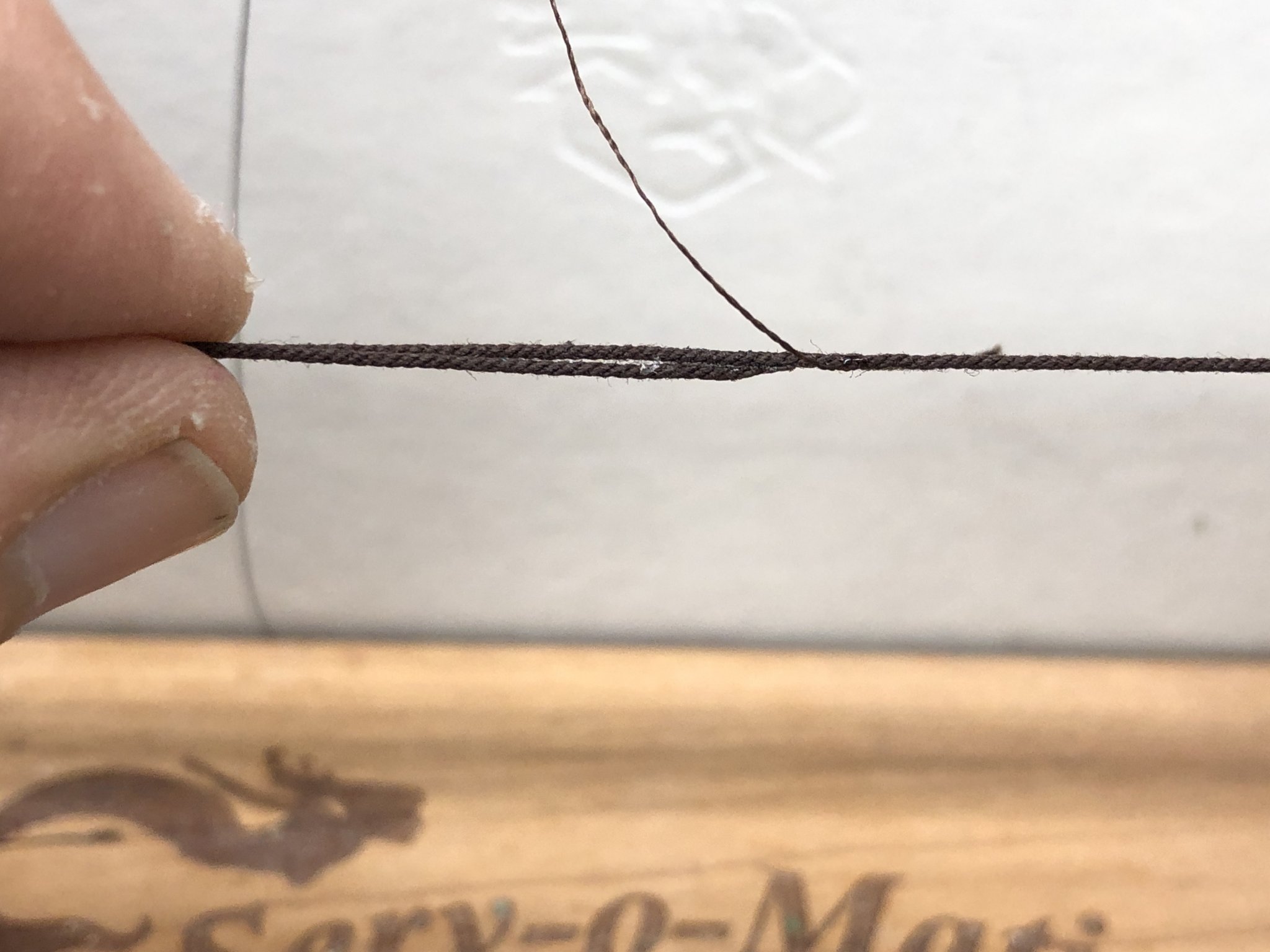
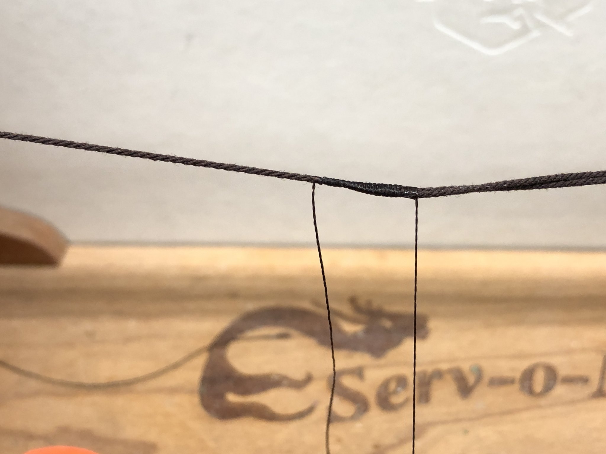
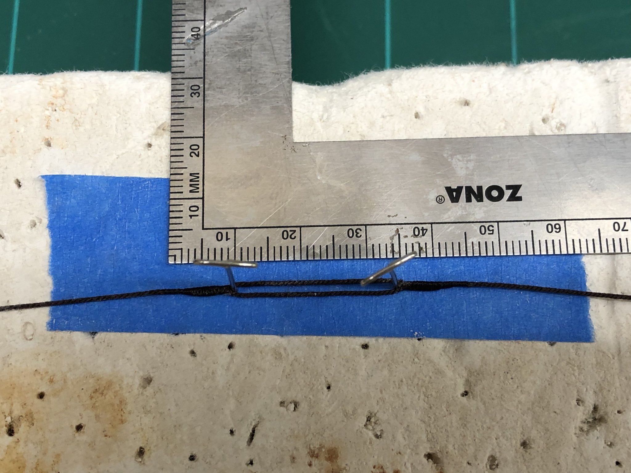
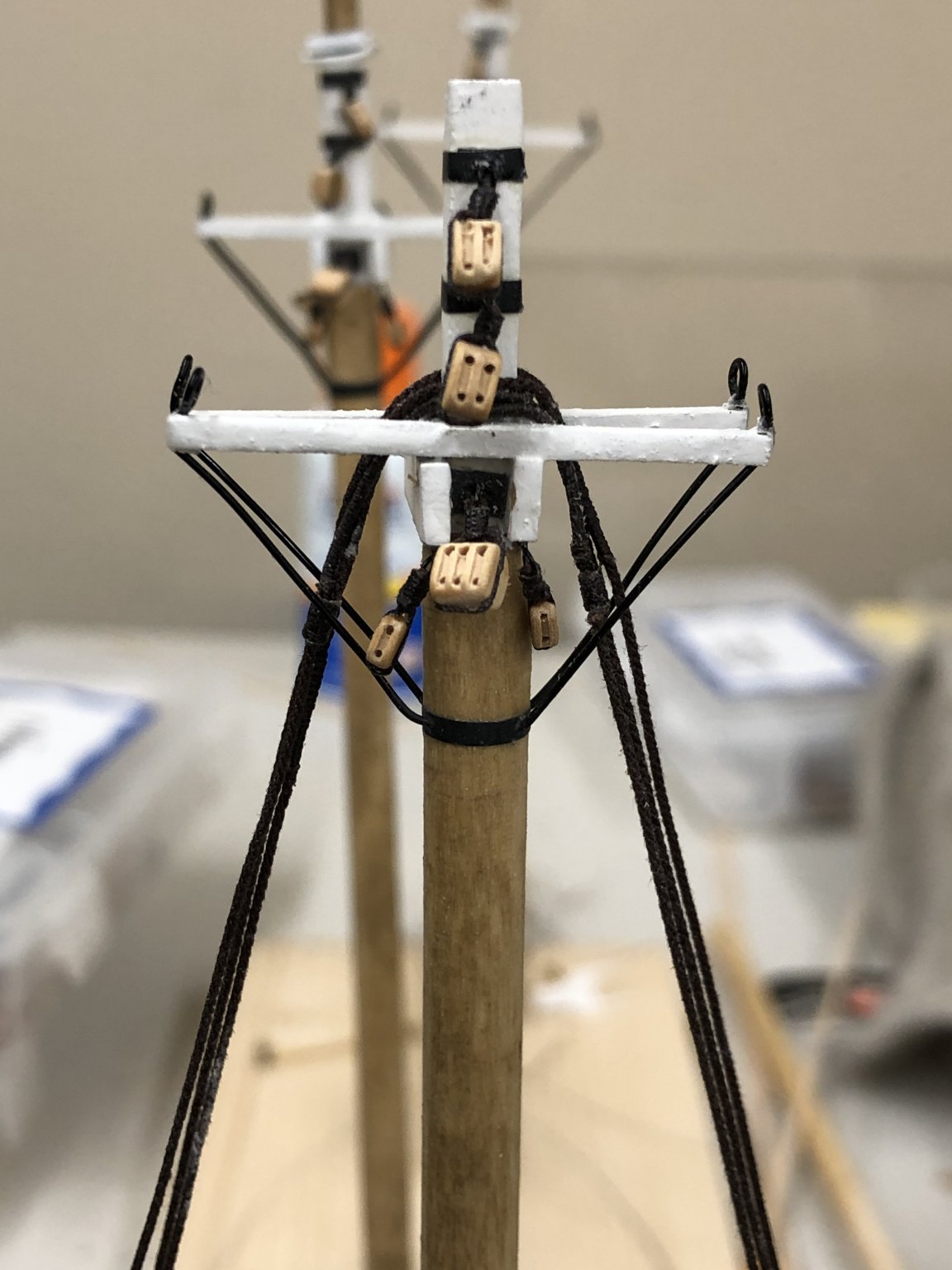
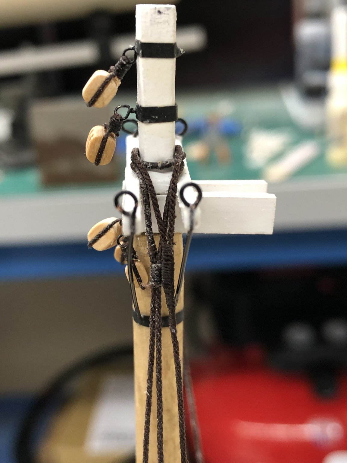
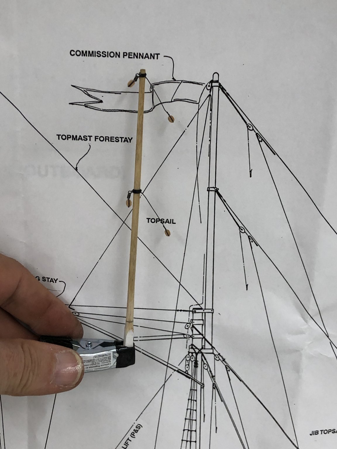
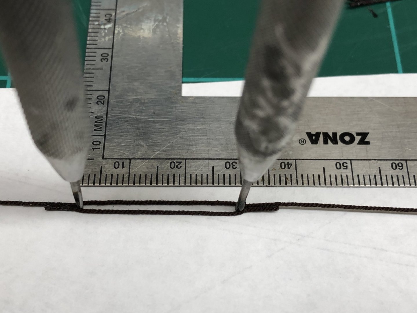
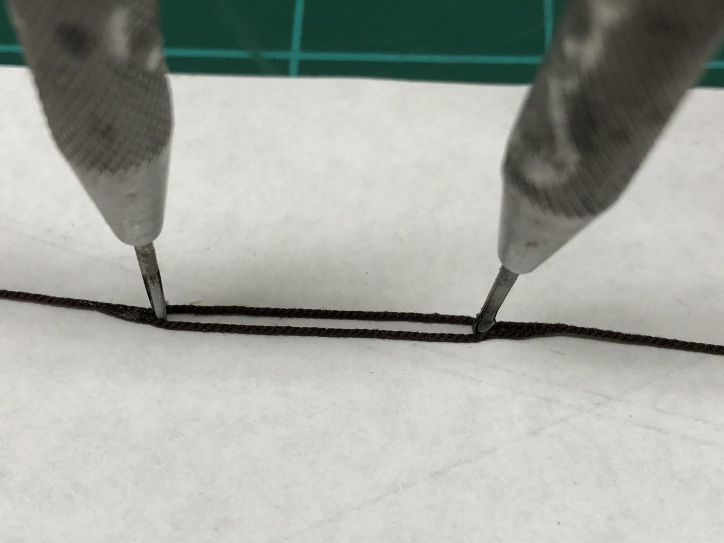
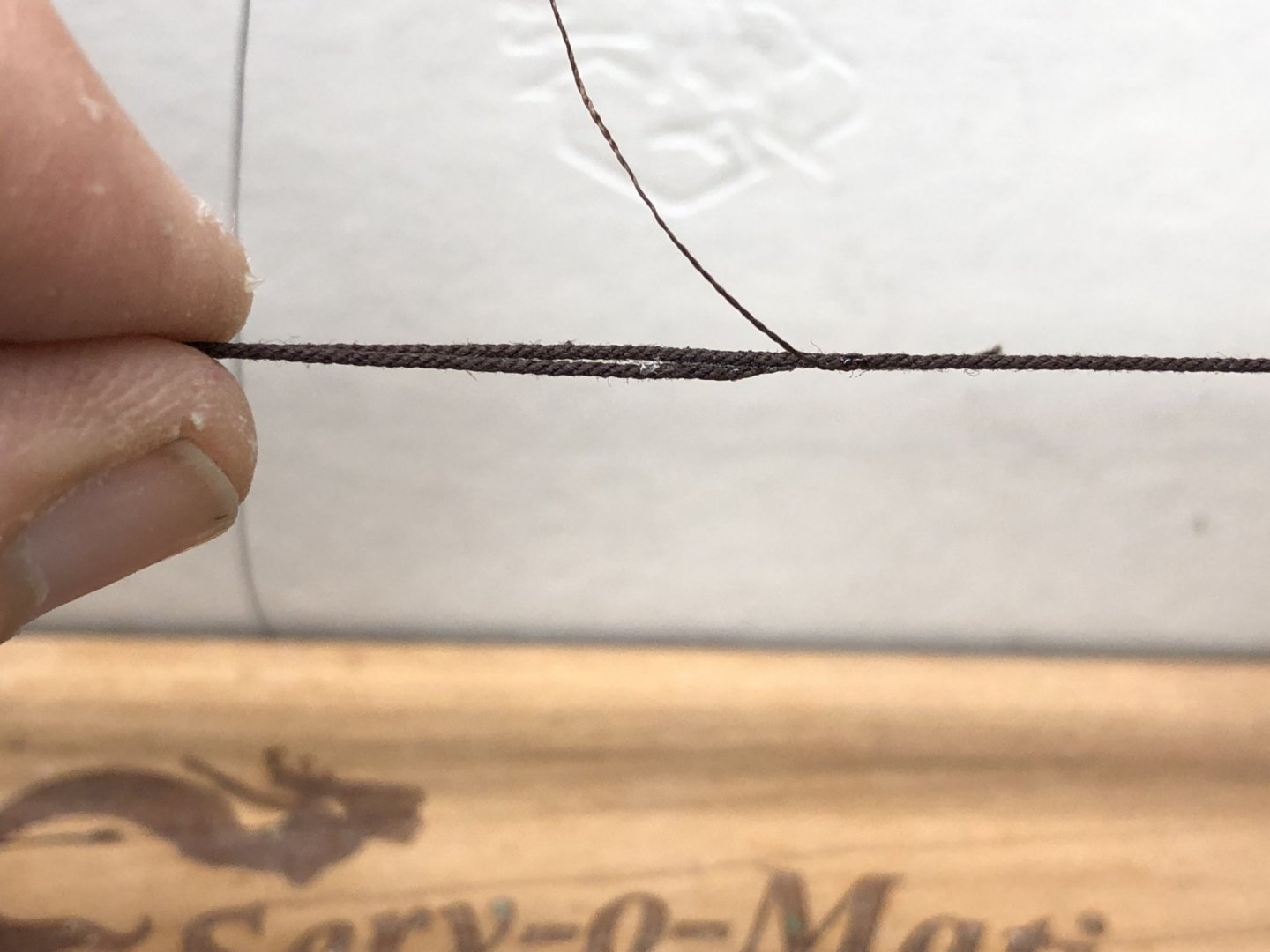
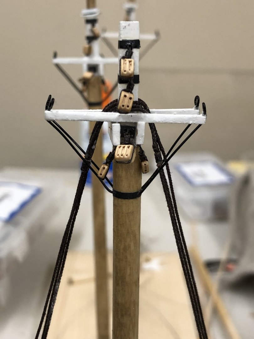
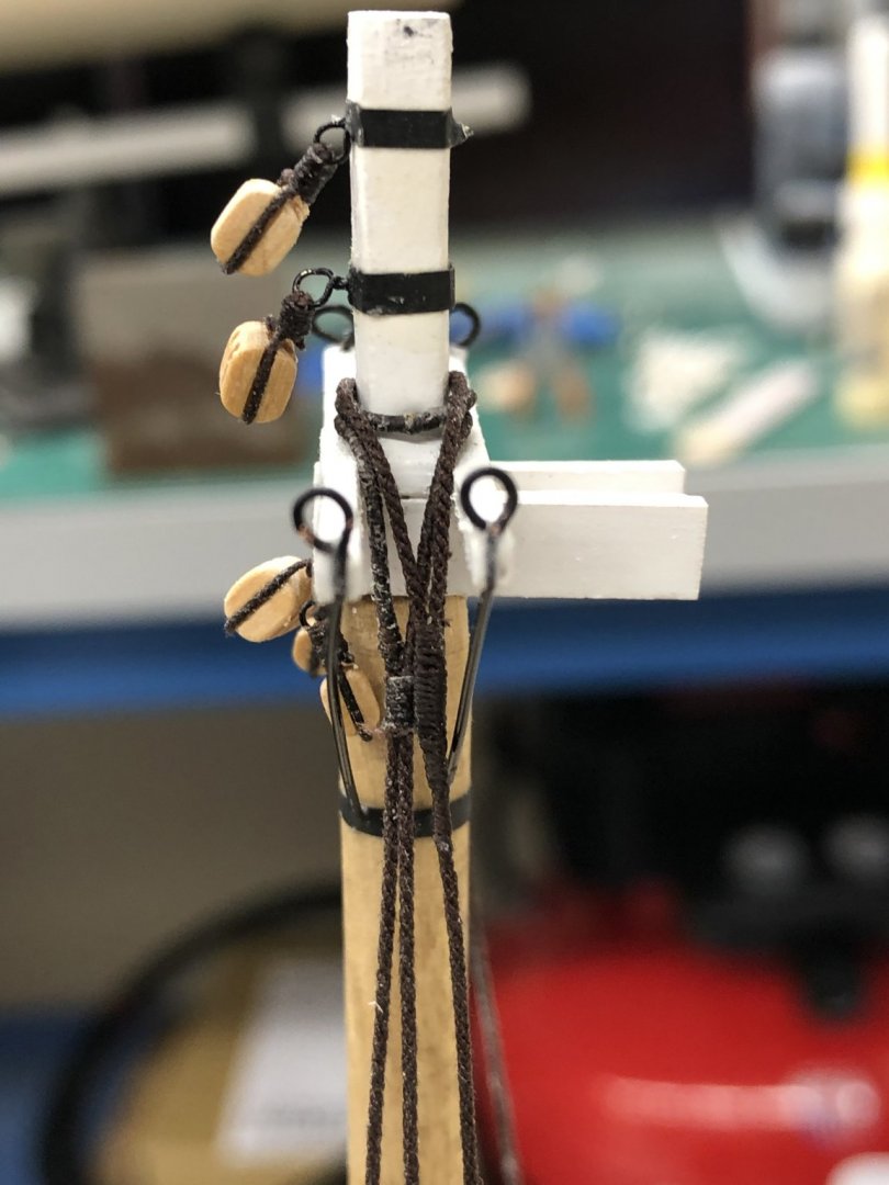
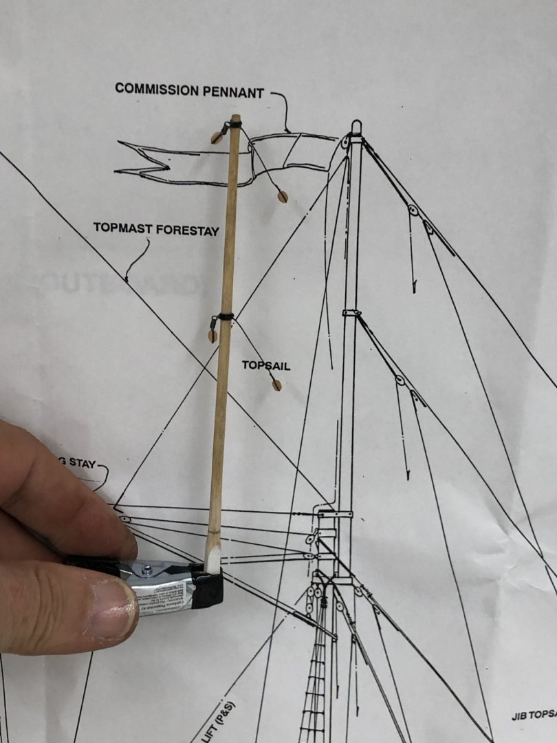
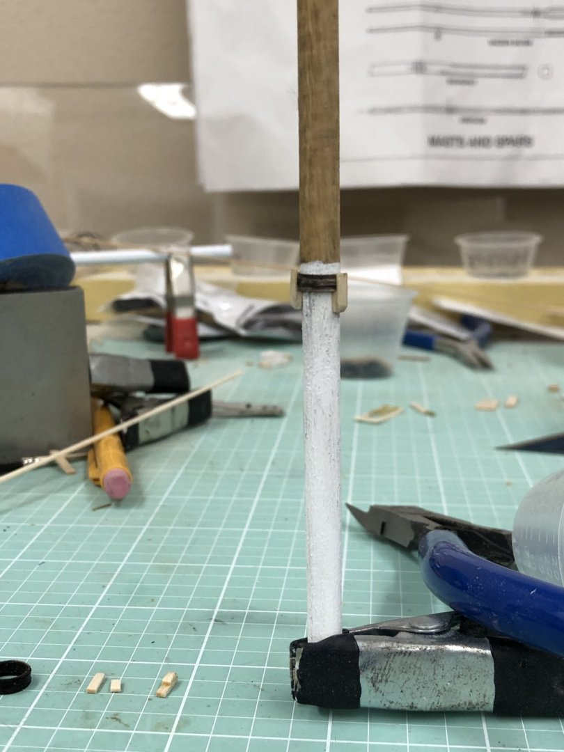
 While working sails (slowly) I decided to proceed with getting the lower shrouds ready as I intend to have the masts as completely outfitted as possible before installing them on the hull. I took some measurements and decided on 40mm as the portion of the loop shrouds that should be served to place the seized junction as shown in the shroud detail on sheet 2. That proved to be fairly easy (especially compared to the serving I did on Niagara). The third shroud for the main and mizzen took a bit more effort. After some experimentation I figured out that to make the two "splices" to add the center "loop" was easier accomplished by using thick CA to glue the loop to the shroud first (after stiffening the ends of the shroud lines with thin CA). I am using Syren .025 Brown rigging line for the lower shrouds so here is the beginning of the "third" shroud. I determined that there should be 25mm of space to fit over the mast and have the two junctions at about the same point as the loop seizing. When the thick CA is dry I used a new, straight Xacto blade to carefully cut the angles on the short piece. My previous attempts to cut the angle and then join the pieces drove me to try this approach which worked much better, at least for me. I then mounted the "third" shroud in my Syren serving machine and served over the joint starting about 3-4mm prior to the beginning of the joint. I used 50/50 white glue and water on the serving and a very small dab of thick CA on the ends at the start and end of the serving. After the serving was dry I checked to make sure I got the desired 25mm opening. So here is what the lower shrouds look like it a test fit on the mizzen mast.


- 166 replies
-
- 1
-

-
- fannie a gorham
- finished
- (and 1 more)
-
Tom, After several attempts at the foot-rope stirrups using Syren line I finally switched to black wire (24 gauge if I remember or maybe one size smaller). That made keeping them straight and tensioning the foot-rope a bit easier. I considered changing to wire (28 gauge I think) for the foot-ropes too but in the end decided against it because of issuing attaching them to the yards. Nothing insurmountable just an issue I chose not to deal with at the time. If (or maybe when) I build another square rigger I will probably go with wire for both foot-rope and stirrups.
-
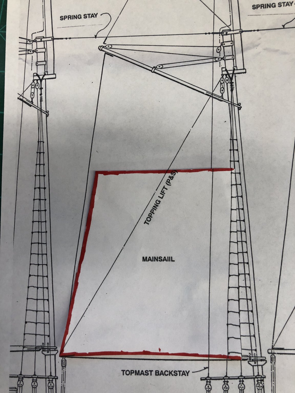
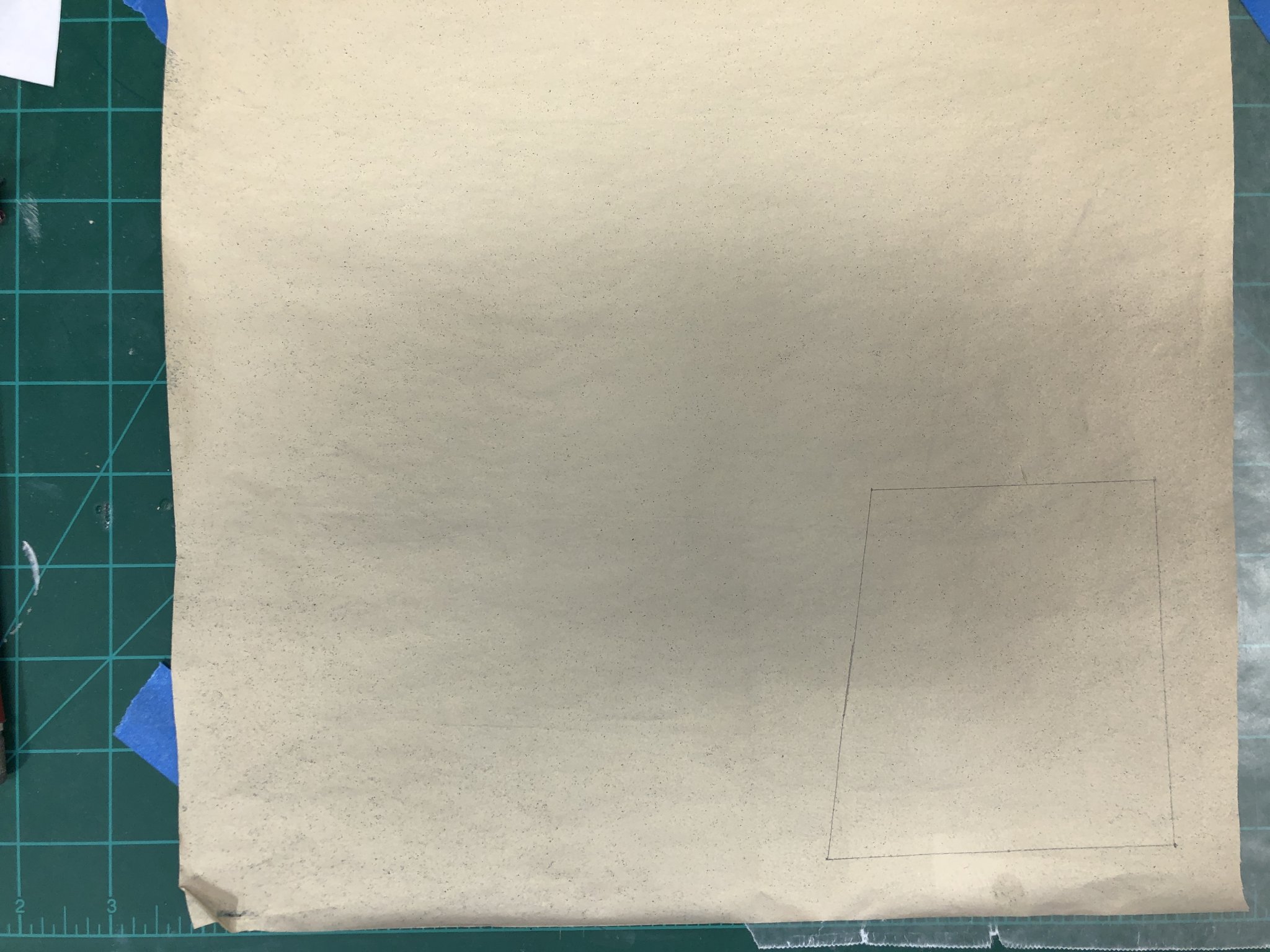
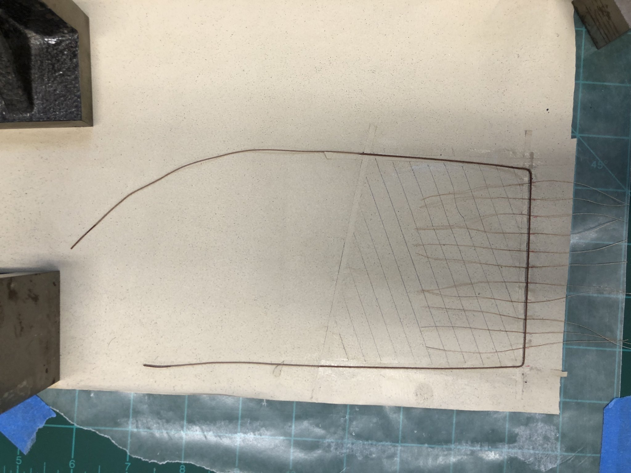
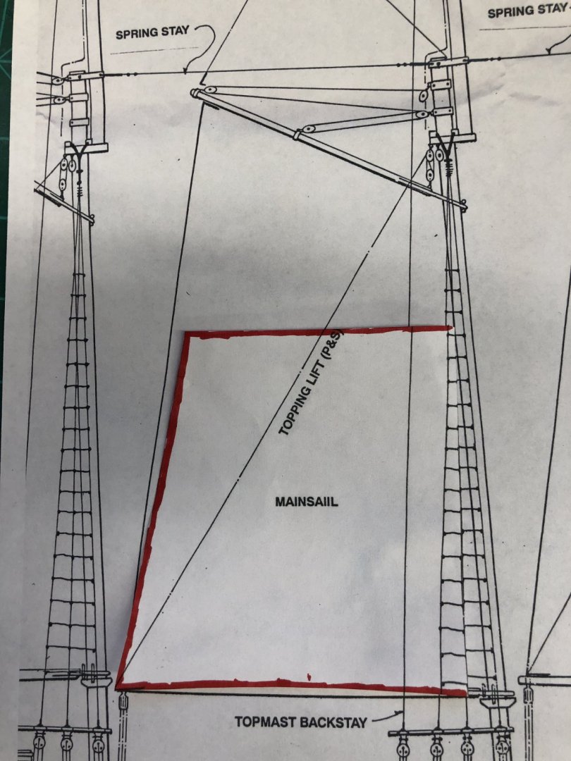
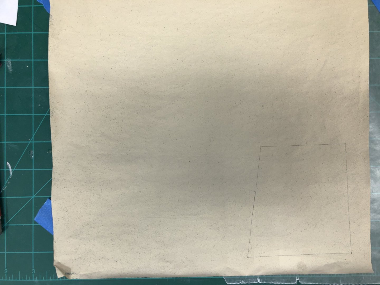
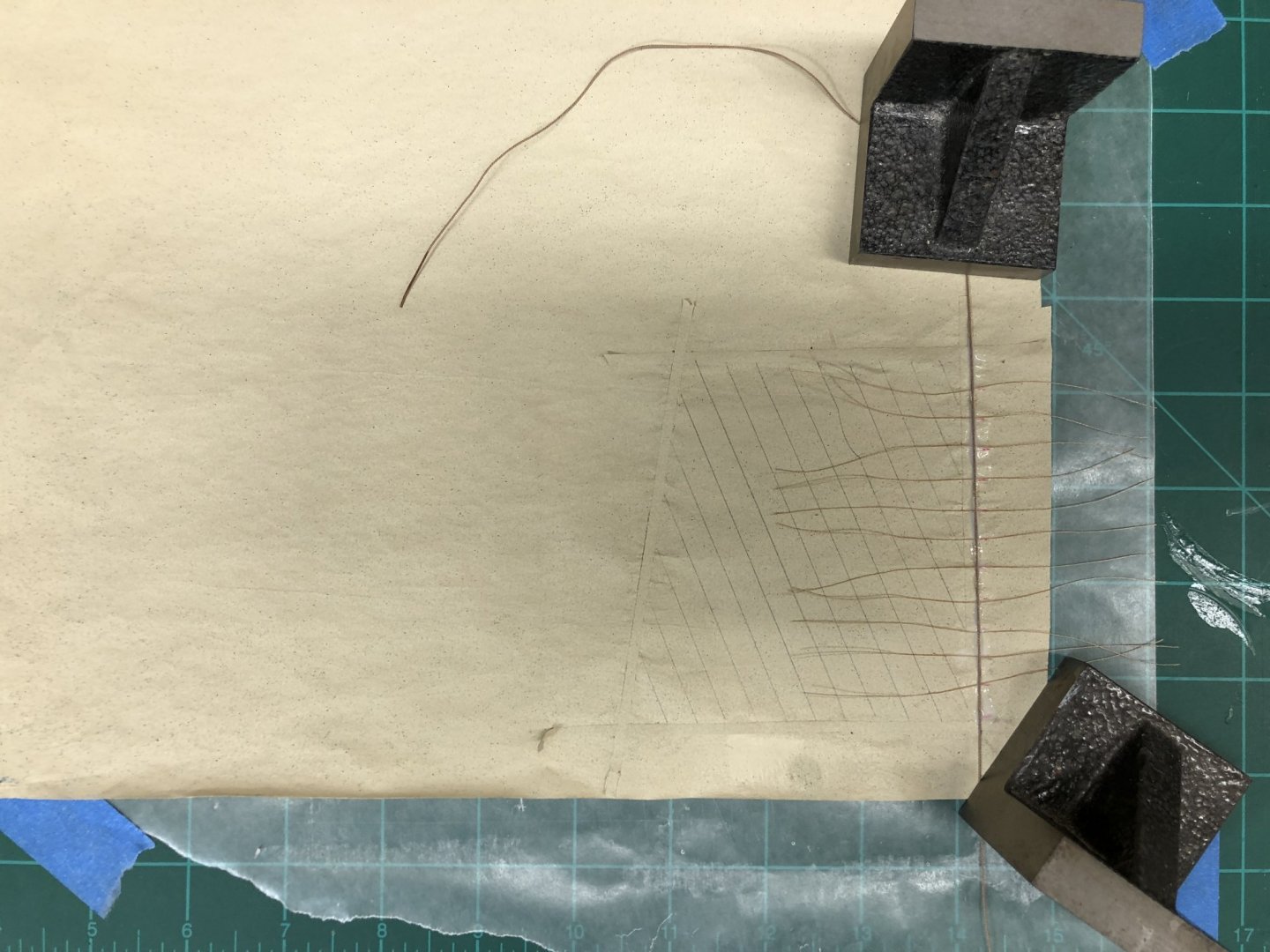
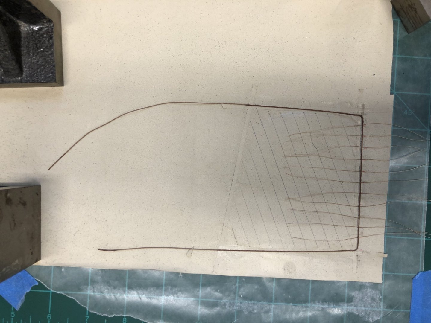
While waiting for the top mast hoops to dry I started on the main sail. I already had a piece of silk span painted with the acrylic Unbleached Titanium White similar to what I used for the mizzen sail (which I am considering doing over - more on that subject later). Based on experience with the mizzen, which was cut down from the sail plan dimensions, I made similar changes to the main sail plan. I went a step further and cut the pattern with the top and bottom parallel to each other making sure the top would still fit the main gaff. You can see the comparison between the sail plan an my pattern in the first photo - the sail pattern is outlined in red. This was different from what I did on the mizzen where the top retained the "extra" fabric above a line parallel to the bottom although the overall height was reduced to about 2/3 of full size. With the sail plan I cut some thin (I aimed for 3/64" but they are probably closer to 1/8") for the reinforcing pieces and outlined the sail plan on the fabric. I added the reinforcing strips on both sides of the material and drew the panel seams with a 2H pencil on both sides as well. I marked the locations for the mast hoops and used a 50/50 white glue water mix to glue pieces of very thin light brown thread to each of the hoop locations. These will be used to attach the hoops to the sail using the built in attachment point on the plastic mast hoops. These have been sanded to reduce them to 1/32" thickness and painted flat buff. The bolt rope is attached using the same 50/50 mixture. Once the bolt rope is attached and dry on all three sides the mast hoops are attached.

- 166 replies
-
- 3
-
-
- fannie a gorham
- finished
- (and 1 more)
-
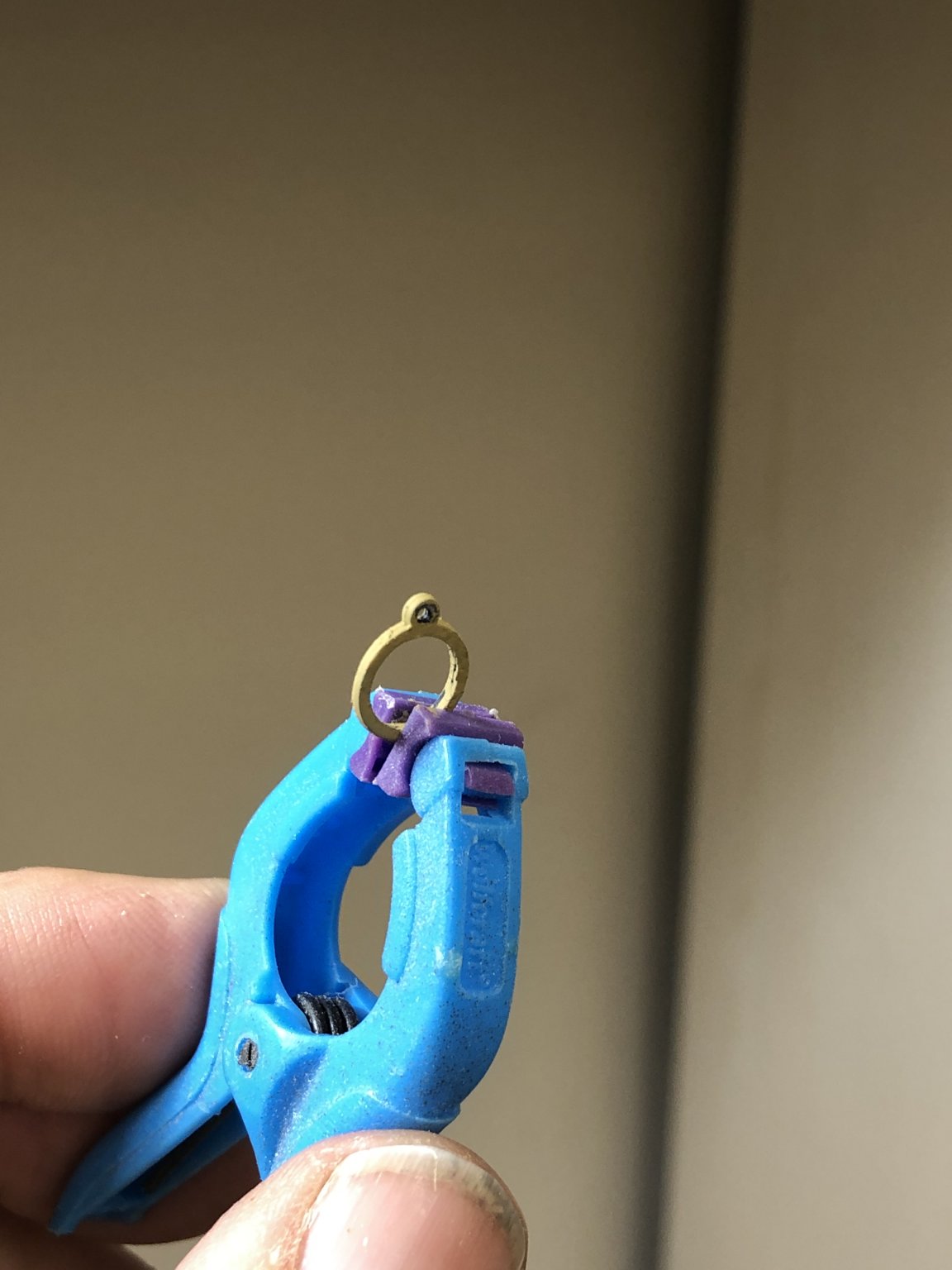
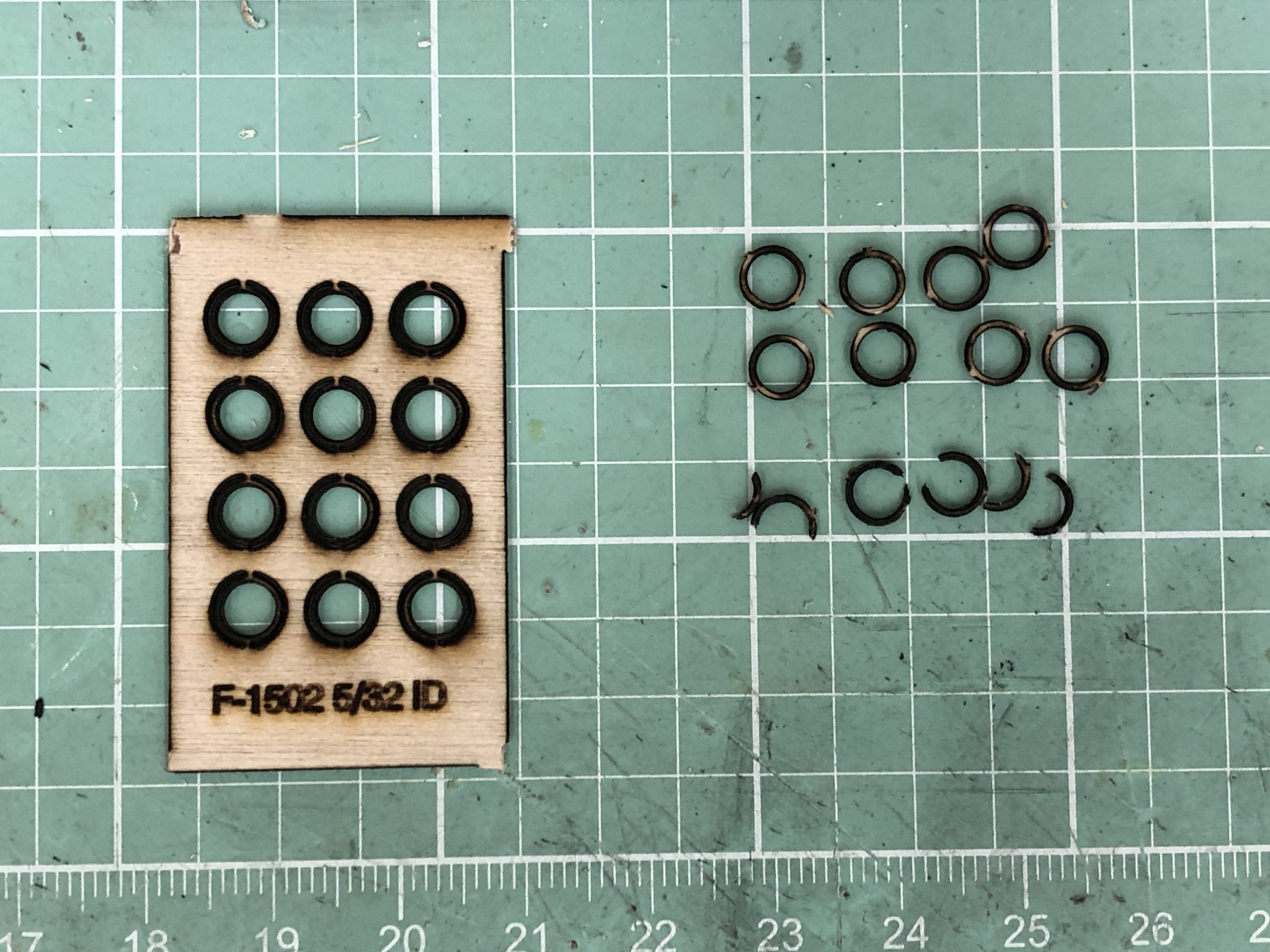
Having rebuilt the fore top mast after forgetting to put the mast cap on before mounting the blocks and recognizing that (according to Picture 9 in the instructions) there are no hoops on the fore top mast I thought I better figure out what to do about the hoops on the main and mizzen top masts. I had previously bought 5/32 X 1/32 hoops from BlueJackets. As I might have mentioned previously I had the devil of a time getting the hoops off the carrier. The picture below shows about an average take from a sheet of 12 hoops - 8 available and 4 are scrap. The plan is to CAREFULLY paint them a flat buff color (same as I did the plastic hoops on the lower mizzen mast (so far)). This is a two step process, grabbing the hoop in a clamp just below half width and painting the top part, then when dry reversing and painting the other half. I had to make absolutely the paint was dry, otherwise the painted part will stick to the clamp and come apart. The second picture was the "take" from the first sheet of hoops. Four out of 12. Luckily I ordered three sheets of twelve and need a total of 20 hoops out of the 36 I have. Need to increase the "yield" or I will be ordering more. FYI - do not even think about trying to sand off the "flash" from the carrier. I lost two of my first set of 12 trying that. Way too fragile for a sanding stick (even 400 grit).

- 166 replies
-
- 1
-
-
- fannie a gorham
- finished
- (and 1 more)
-
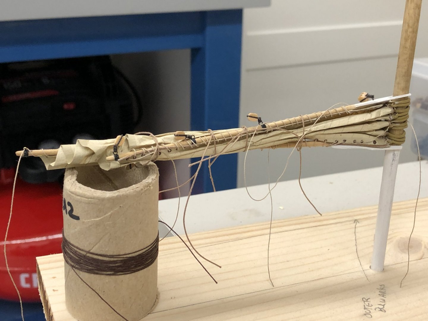
Included in the "messing around" has been the first attempt at a sail. In this case the Mizzen sail (the largest so if I can get this I think the others (main and fore) will be easier). I used the technique shown on U-Tube (Making Sails for Ship Models from Silkspan, Parts 1 & 2) which is considerably faster than my previous method which was from an Admiralty Models course in 2014). I did not take pictures of the intermediate steps but here is what it looks like at this point. I still have to add the parrels on both the gaff and boom as well as figure out how to terminate the line securing the sail to the gaff/boom. I am going to "mess around" with this some more to get a bit more "ship shape" then think about starts on the main and fore sails. I am got going to model the top sails but probably will include the top sail halyards although getting access to belaying pins in the boom jaws looks like it would be a challenge.
- 166 replies
-
- 2
-
-
- fannie a gorham
- finished
- (and 1 more)
-
Thanks John. Mr. BlueJacket - I just finished fabing a new fore top mast so I appreciate the suggestion but I have already drilled the holes for the main topmast stays and the bail in the mast cap and am concerned about its ability to support additional "manipulation".
-
Spent the morning putting the blocks on the fore Topmast. Since the Flying Jib and Jib Topsail halyard blocks are on pendants I decided to use the 28 guage black wire to strop them instead of the .012 brown Syren line I used on the other blocks. This way the wire will help support the halyard, downhaul and sheet lines which will all be hooked together a few inches above the deck. I got everything together, including the extra block aft at the jib topsail level for the fore topsail, which according to Photo 9 is set flying, with no hoops, above the jib topsail stay, rather than above the flying jib stay. That was fine, as far as it went. Then I realized that I should have put the mast cap on the top mast before adding all the blocks. As it stands now there is no (easy) way to get the mast cap installed. Lesson learned for the other two top masts while I decide how to deal with the fore top mast.
- 166 replies
-
- 6
-
-
- fannie a gorham
- finished
- (and 1 more)
-
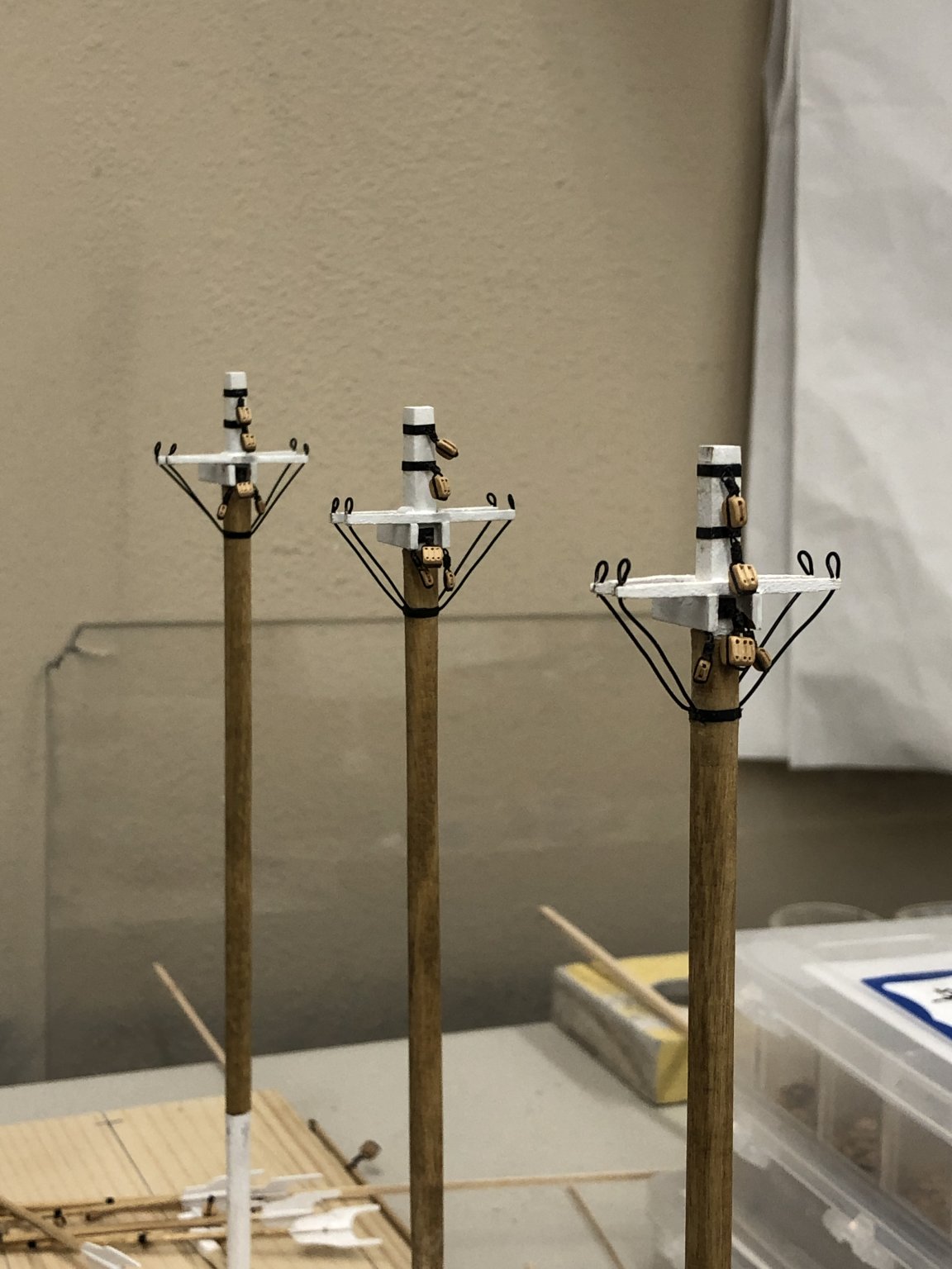
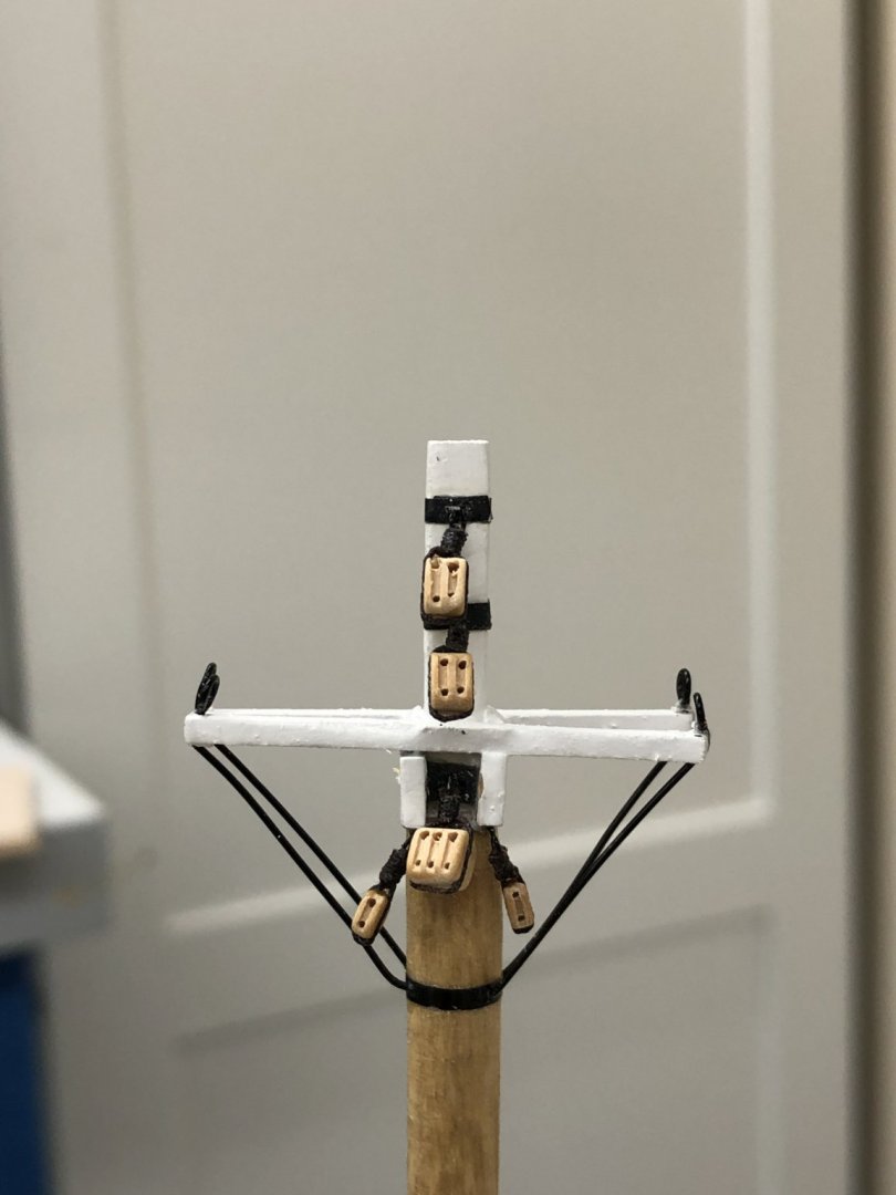
Continued to add blocks to the lower masts. I have all the common blocks (throat and peak halyards, topping lifts) completed - now to get the unique ones on each lower mast. Drawing is not all that helpful - shows some "extra" blocks but without clearly identifying what they are for. Need to carefully look at the sail plan as there are at least two head sails that terminate at the top of the lower foremast Here are the lower mast tops with the common blocks installed.

- 166 replies
-
- 3
-
-
- fannie a gorham
- finished
- (and 1 more)
-
Continuing to "fiddle around" I completed the lower Mizzen mast adding the tape (aka metal bands - and added a backing plate for the throat halyard triple block) and the peak halyard and topping lift blocks. Fore and Main masts are next. Thinking about adding serving to the center parts (to just below the bolster) for the lower shrouds. I used the Syren Serving machine for the much more extensive serving on the Niagara so I know what is required. Just wonder if that is "going overboard" at 1/96 scale. The instructions (page 13 - sketch 17) appear to show serving on the lower shrouds and forestay. Something to think about.
- 166 replies
-
- 3
-
-
- fannie a gorham
- finished
- (and 1 more)
-
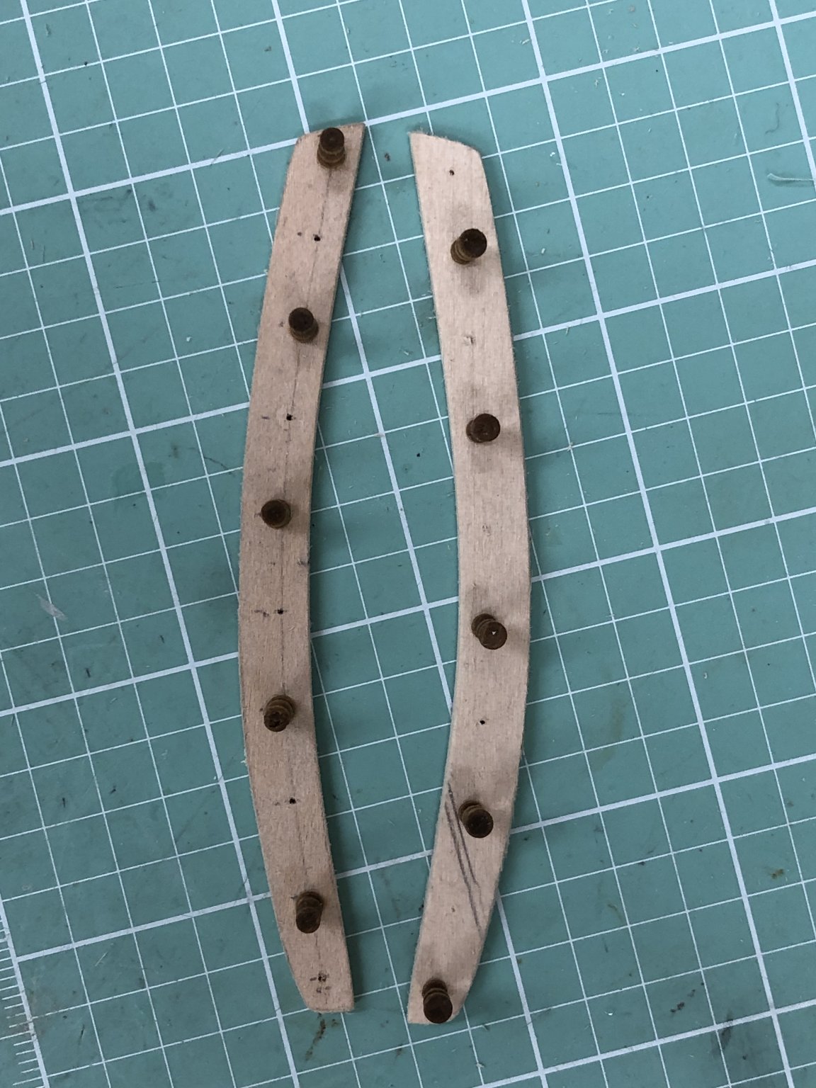
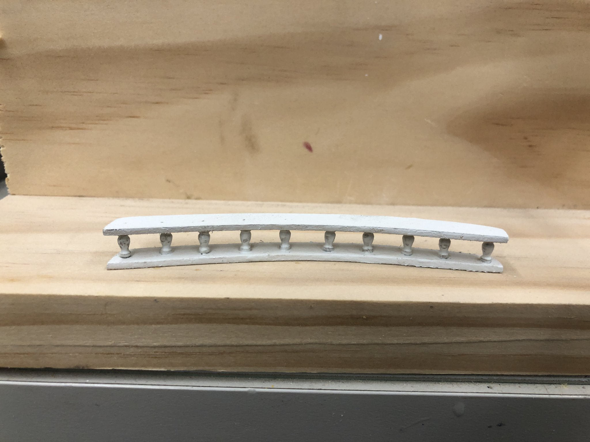
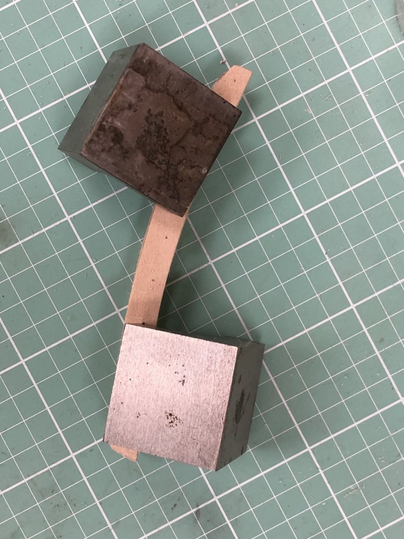
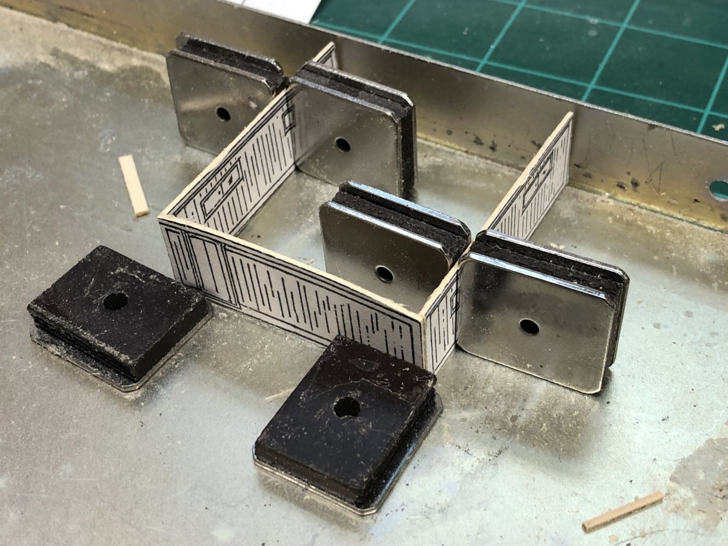
Worked on the stern taffrail to see how the wooden pillars would look. I fabed the top (1/16" thick) and the bottom (3/32" thick) and then marked where the pillars should go (3/16" spacing as best I can tell from the drawing) on each piece. To make sure I have the locations in the same place top and bottom I used a drill press to drill a small (#70) hole through both pieces while keeping them clamped together. I glued every other pillar to the bottom rail and then the intervening ones to the top rail remembering that the pillars have a top (not symmetric). When that dried I joined the two pieces together using some machinists squares to provide some weight and (hopefully) everything would line up. In the end I had to move one pillar to get the spacing closer to the desired state but overall it looks okay. Here ius how it looks now after a coat of primer (which is almost white).

- 166 replies
-
- 4
-
-
- fannie a gorham
- finished
- (and 1 more)
-
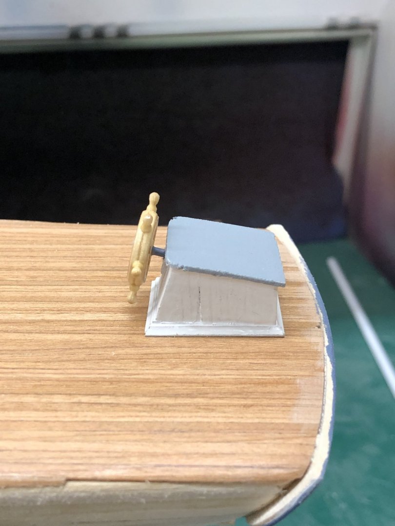
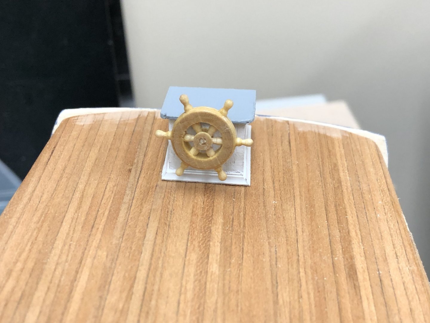
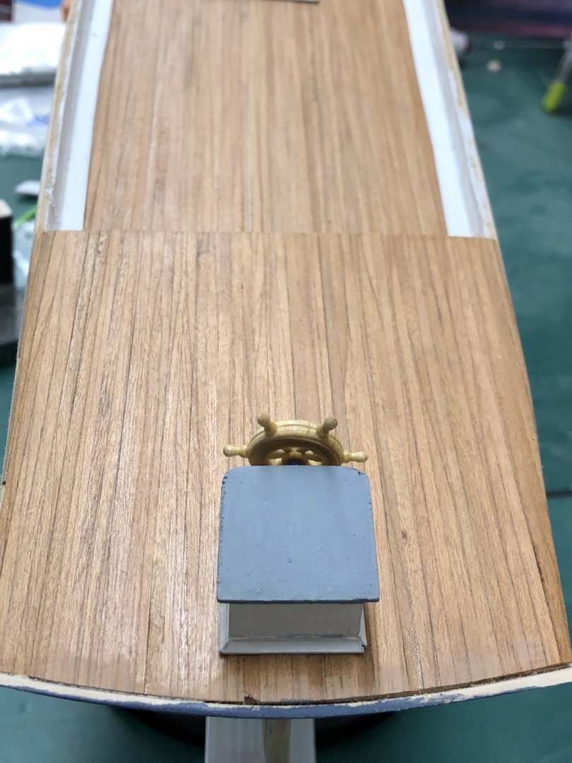
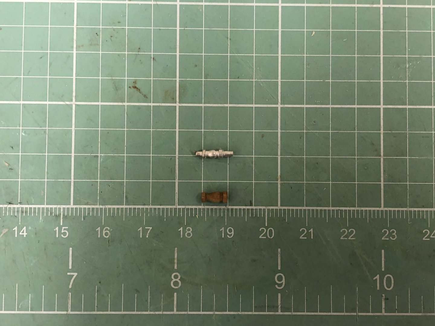
I decided I did not like the ship's wheel provided (Britannia metal again). I looked around and found a wooden wheel at Model Expo that is only a little (1/8") bigger in diameter than the one provided. The real issue with the Model Expo one is width, at scale it would be over a foot thick - not very realistic. Still it probably would look better than I could every get the Britannia metal one to look so I thinned it down some (still almost 1/8" thick) and painted it with gloss clear. Here is the completed wheel box sitting on the quarterdeck.
- 166 replies
-
- 3
-
-
- fannie a gorham
- finished
- (and 1 more)
-
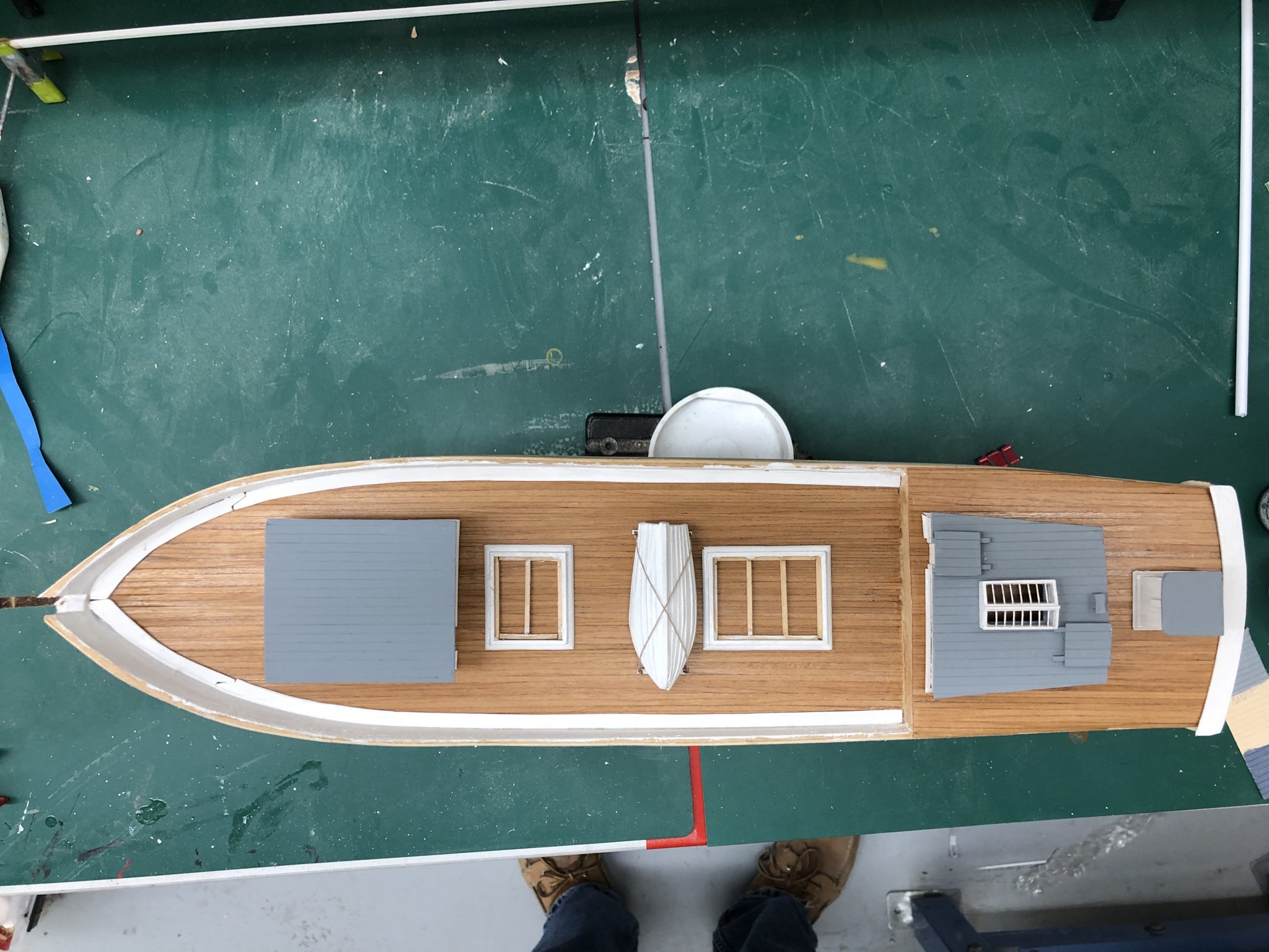
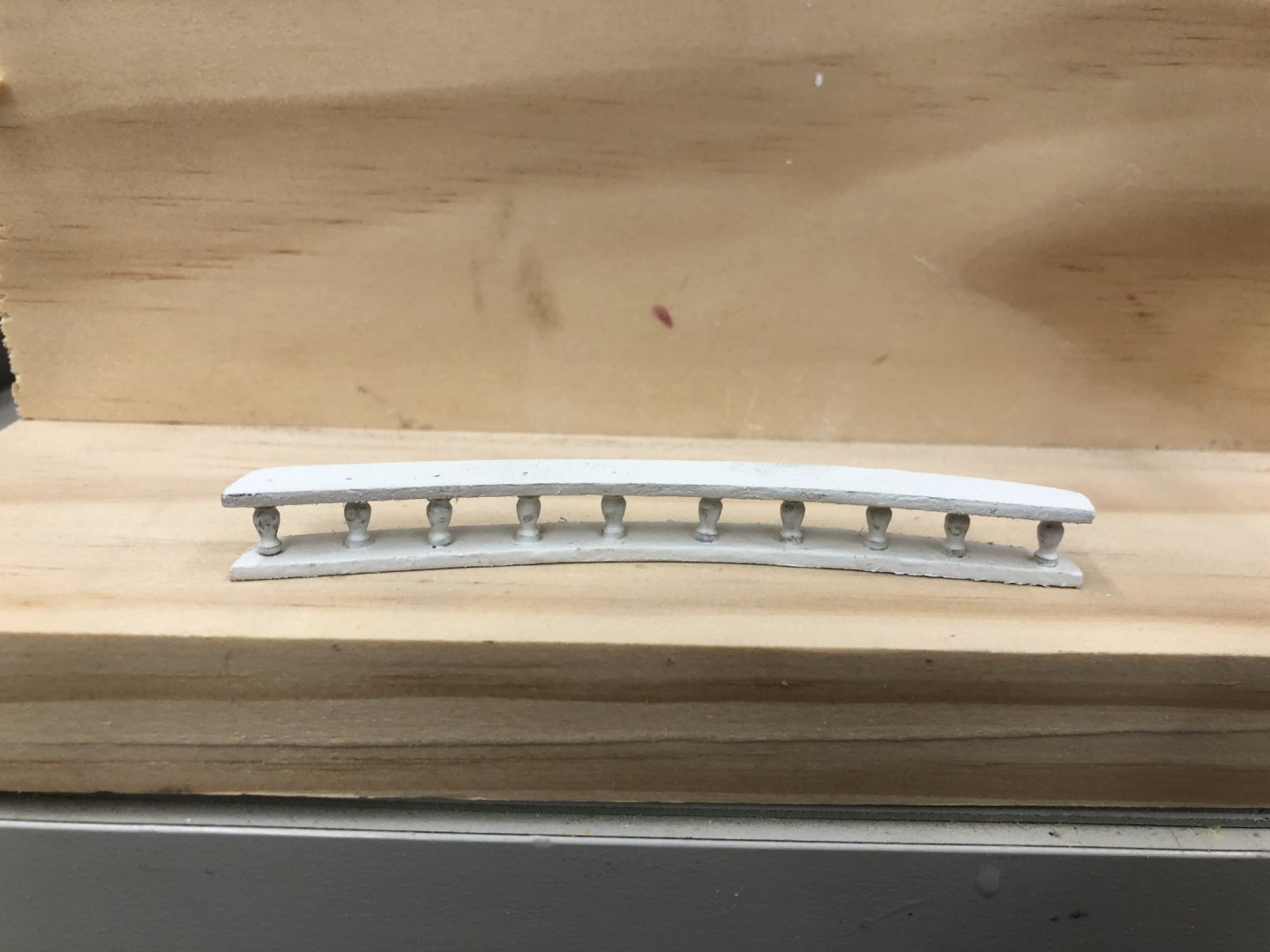
I am still working "odds and ends" waiting for paint to dry. Given my dislike of Britannia metal fittings I decided I had to do something different with the taffrail stanchions. I purchased some wooden (not sure what kind of wood - not that it matters much since they will be painted white) pillars which are 6mm tall which as you can see below is a bit taller than the ones supplied in the kit. I cut the pins off the kit stanchion and it measures 5mm (.04") So I have to decide to just substitute them and not worry about the approx 3/64" difference in length (more than 1/16 but less than 3/64s) which would be about 8" at scale. I have my doubts that it would be that noticeable if I did nothing but I decided to thin down the base of the railings from the 1/8 (at the stern) and 5/32 (on the sides) to 1/16 and 3/32 respectfully to get back 6" of the overage. I will probably have to use the thickness sander to get something 5/32" as nothing supplied in the kit is that thickness. Although the paint is not yet completely dry I could not resist trying the deck furniture (such as it is) "on for size". So here are two shot sof what I have done so far.

- 166 replies
-
- 5
-
-
- fannie a gorham
- finished
- (and 1 more)
-
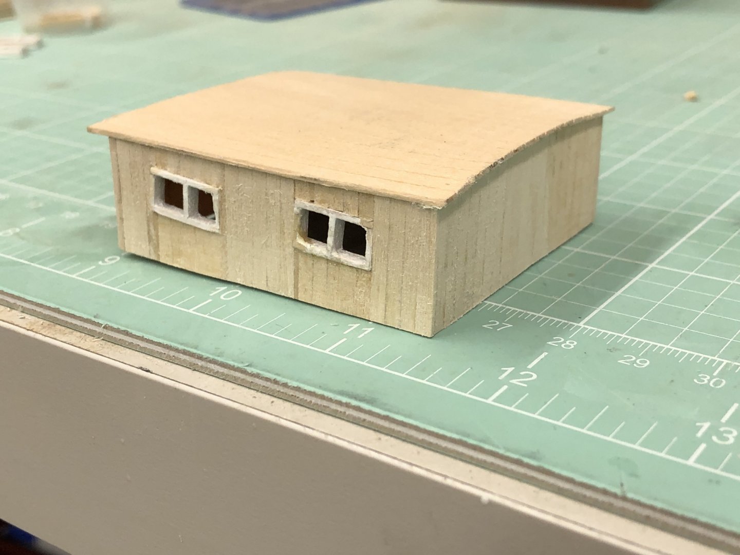
Still working the deck furniture (hard to stop once I get going). Here are the two hatch coamings after assembly, one coat of primer and a 220 sanding. I think I did a fairly good job getting them the same width. The main hatch is slightly (1/8") shorter than the drawings as I fear with my lifeboat being somewhat wider than the one on the drawing there may be an issue. I have all the other structures completed and in the paint shop. Will get pictures when they are "ready for prime time".
- 166 replies
-
- 2
-
-
- fannie a gorham
- finished
- (and 1 more)
-
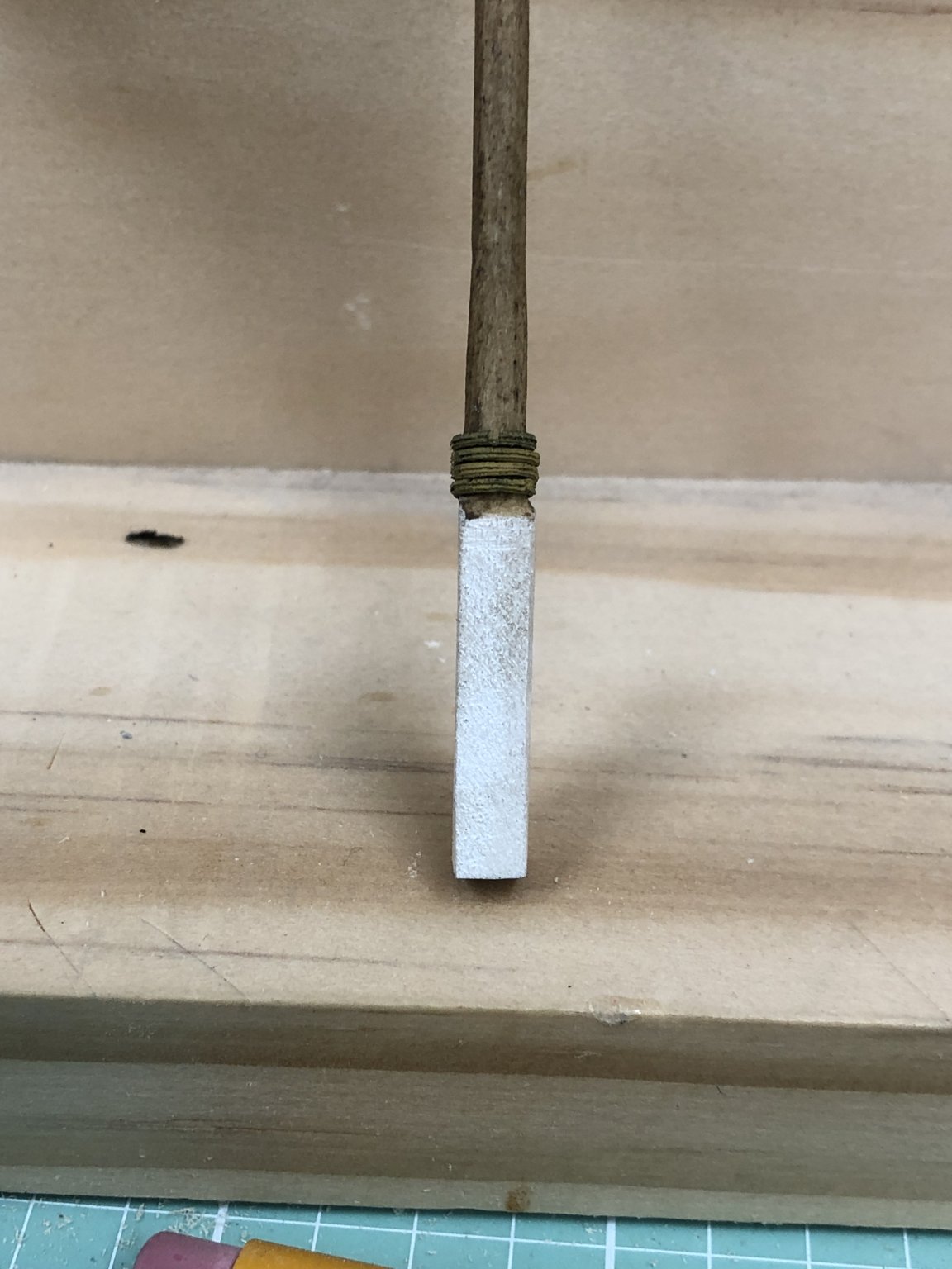
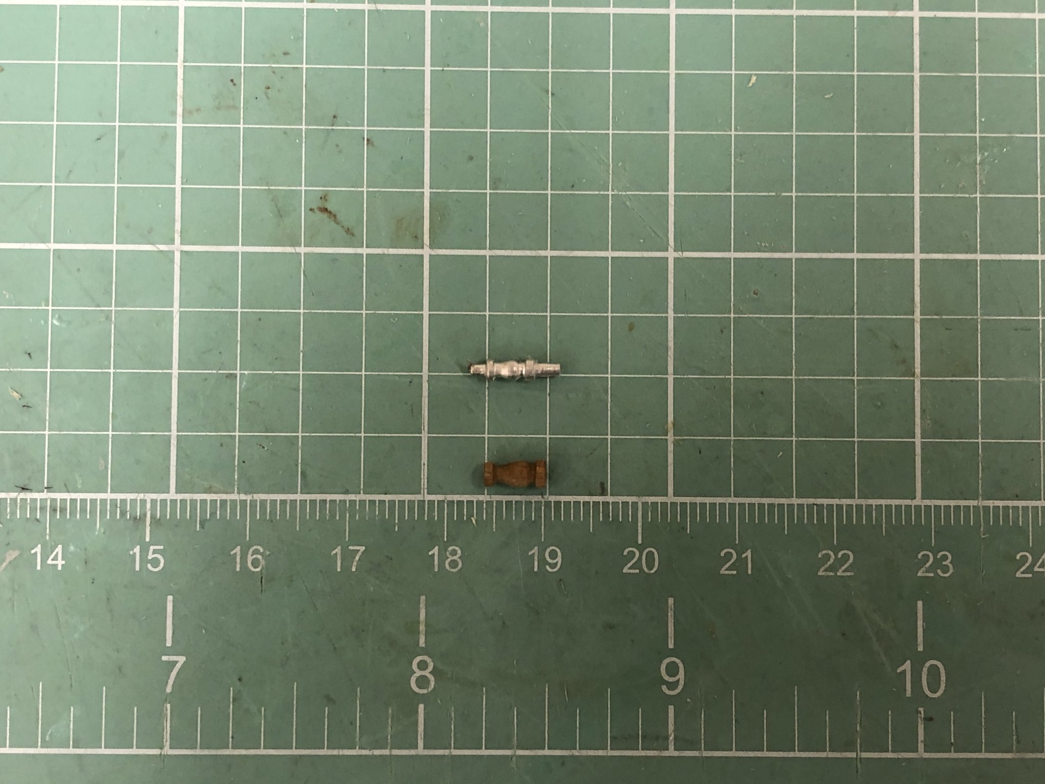
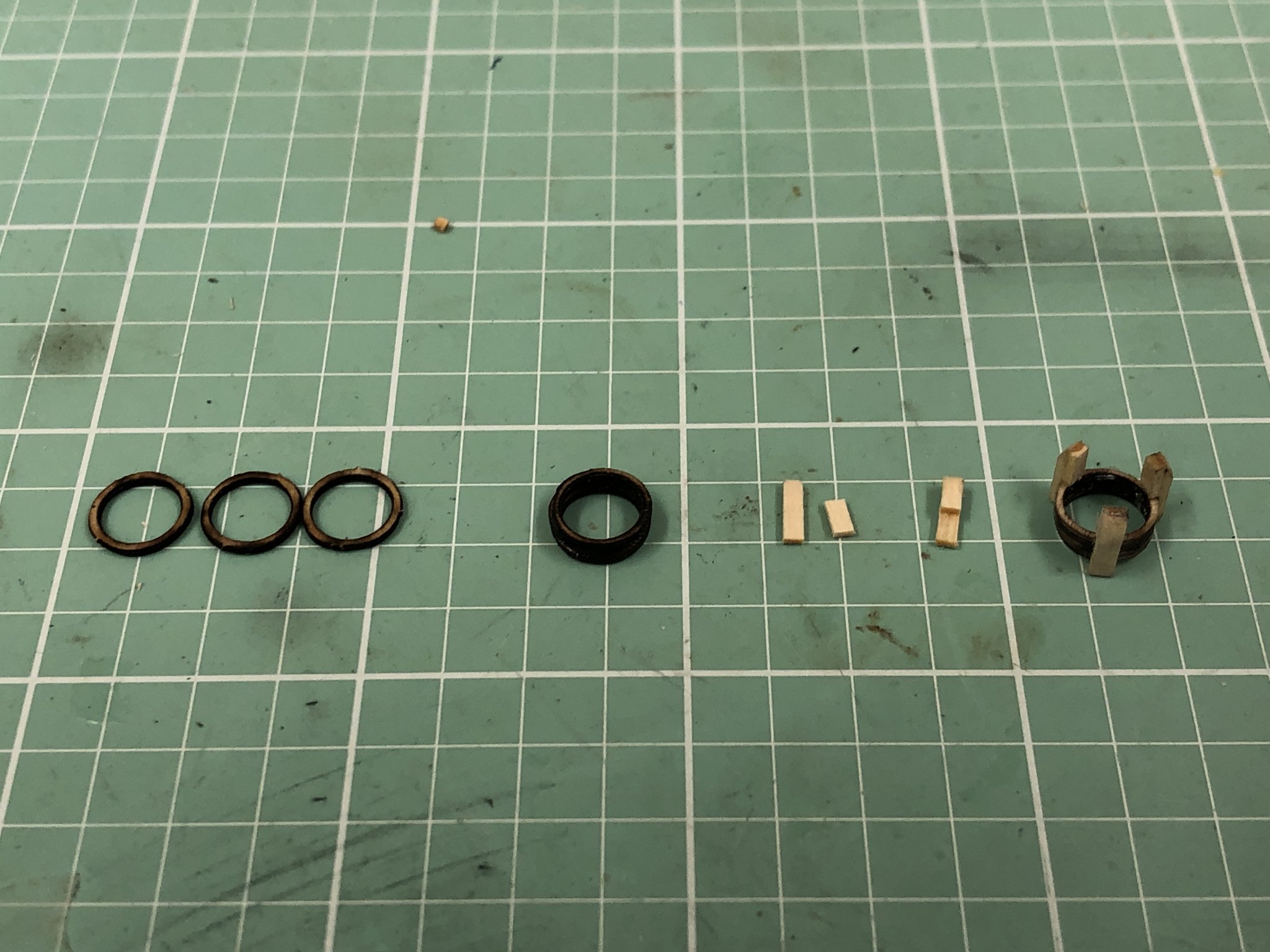
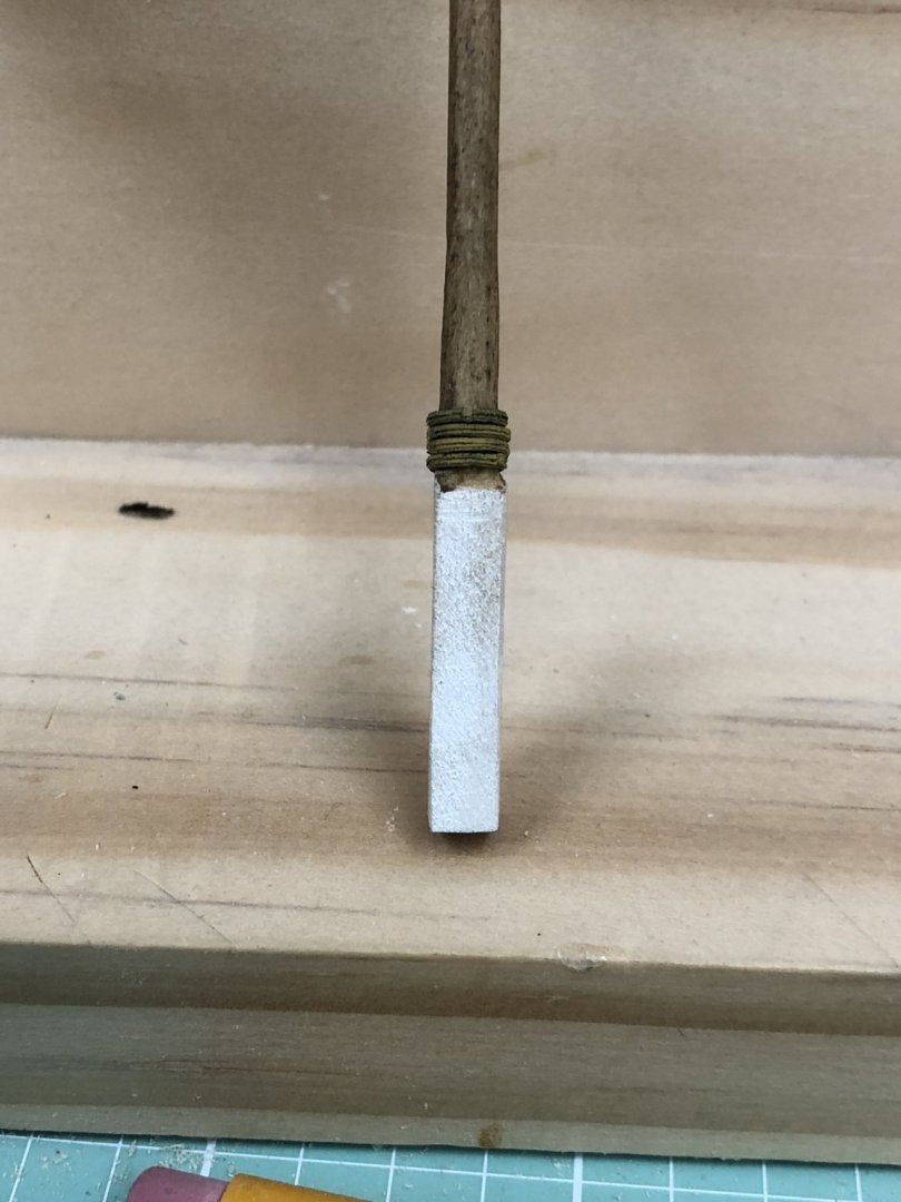
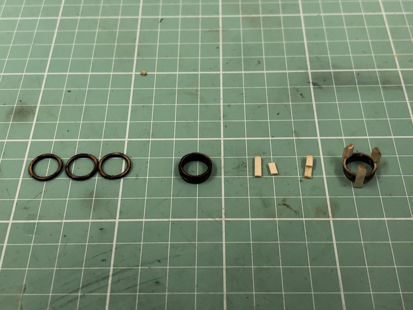
Fiddling around while the paint dries. I shifted from water based acrylic to enamel and it takes at least 24 hours (usually more like 48) for the enamel to dry - but it usually only takes one coat (over the primer which for some reason dries much faster) to cover where it was taking 3-4 coats of the acrylic. I am probably doing something incorrectly but have no idea what. Anyway, I decided I did not like the Britannia metal boom rests that came with the kit. They seem a bit "clunky" and I have never had much luck getting them painted to my satisfaction so I decided to make my own. I started with some mast hoops (1/4" in this case) which are just a bit bigger than the lower masts. These are from Bluejackets and seem to have more than the usual amount of laser char and are 1/32" thick. I stacked three of them together to make a 3/32" thickness (thin CA) and then tried to remove as much of the char as I could without crushing the who;e thing. The individual hoops are quite fragile but three together is much stronger (dah). Using this as the base I cut pieces of 1/16" X 1/32" strips into pieces 1/4" and 1/8" long and glued them together (again thin CA) to form an "h" the shorter piece on top on the longer. I made three of these and glued (wood glue this time) the thinner portion of each to the outside of the hoops evenly spaced around the hoop. Once dry I rounded what would be the lower (thicker) end of the support piece and test fit it on the mast. It will, of course, look better painted but I think I will make two more and consign the kit parts to my "orphan parts bin". FYI - on my way to Minneapolis for my yearly dose of really cold weather - coming back on Tuesday - four days is all I can take.
- 166 replies
-
- 2
-
-
- fannie a gorham
- finished
- (and 1 more)
-
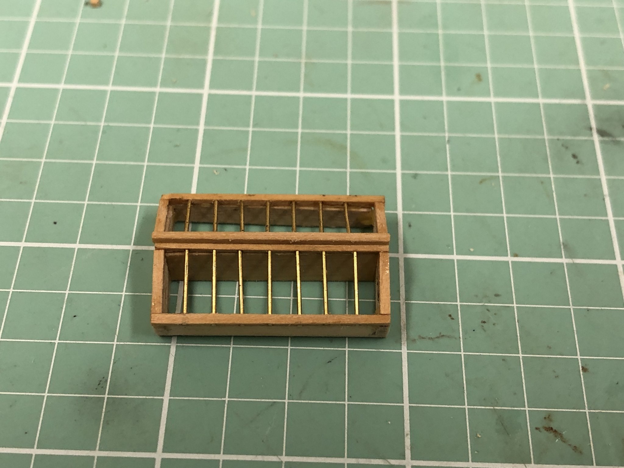
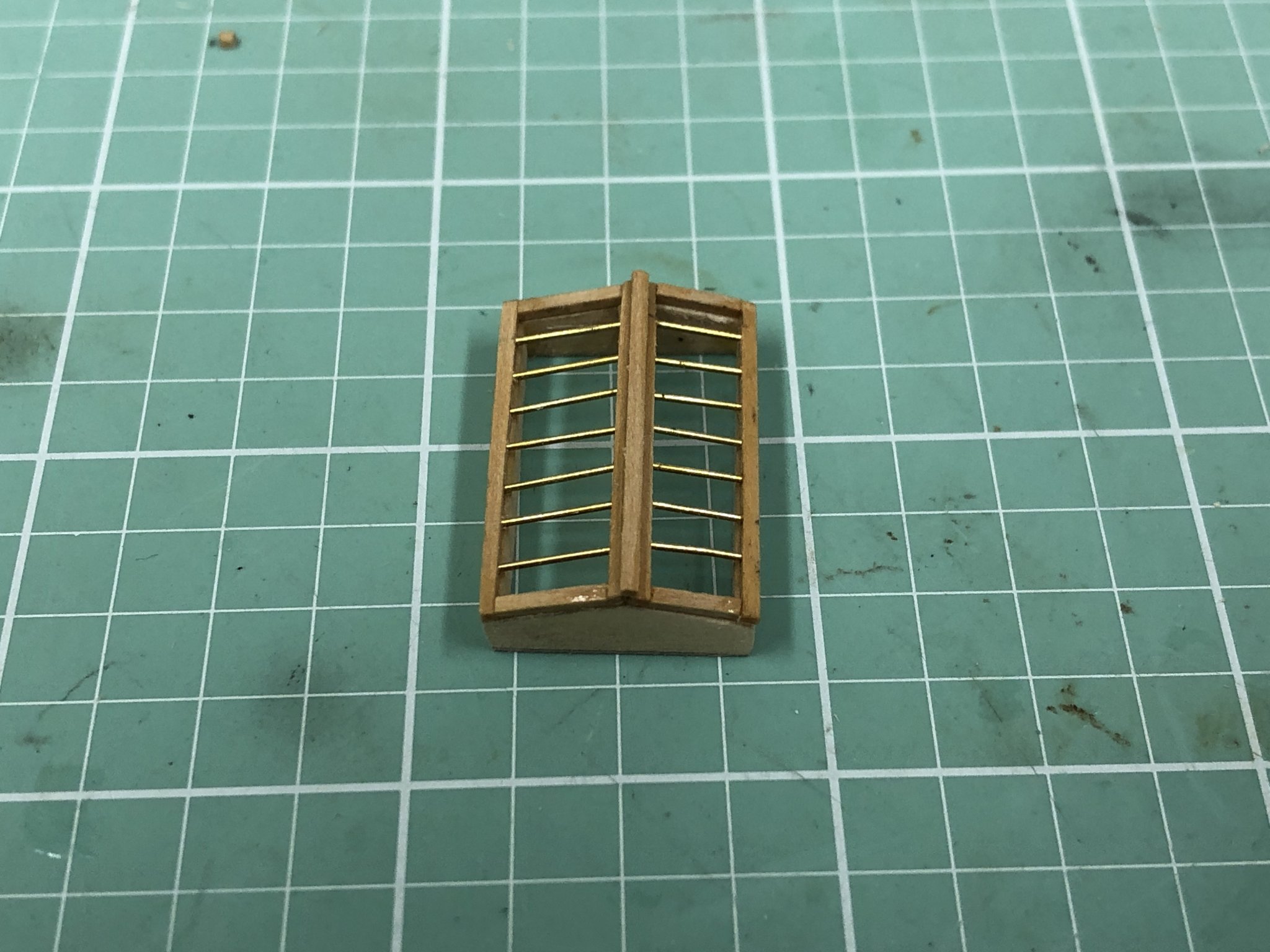
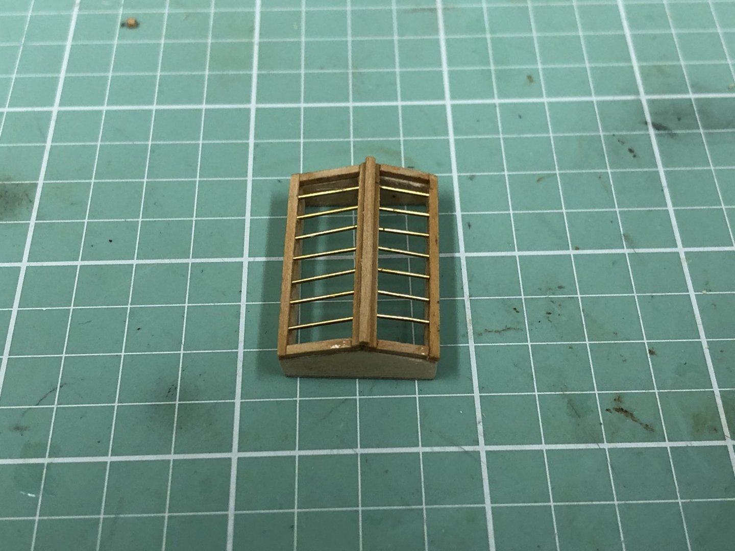
Home with new car and the skylight is complete (except for acetate and paint (not in that order). After several instances of getting most of the holes drilled in the 1/32 boxwood frame and then having the wood splinter or otherwise misbehave on one of the last holes, I stated using a #78 drill first and then widening it with the #76. That seemed to work better but the pieces of the frame, which are about one inch long with seven holes removing almost half the wood the are fragile. I got two more completed and the wire installed and then glued both in place on the previously assembled frame. Here is how it looks. I decided to cut a hole in the roof of the deck house instead of painting the roof black under the skylight. I will see how it looks when in place and may then decide to paint most of the deck under the aft deckhouse black if it shows "too much".

- 166 replies
-
- 5
-
-
- fannie a gorham
- finished
- (and 1 more)
-
Going off line for a few days to pick up new car in South Carolina.
-
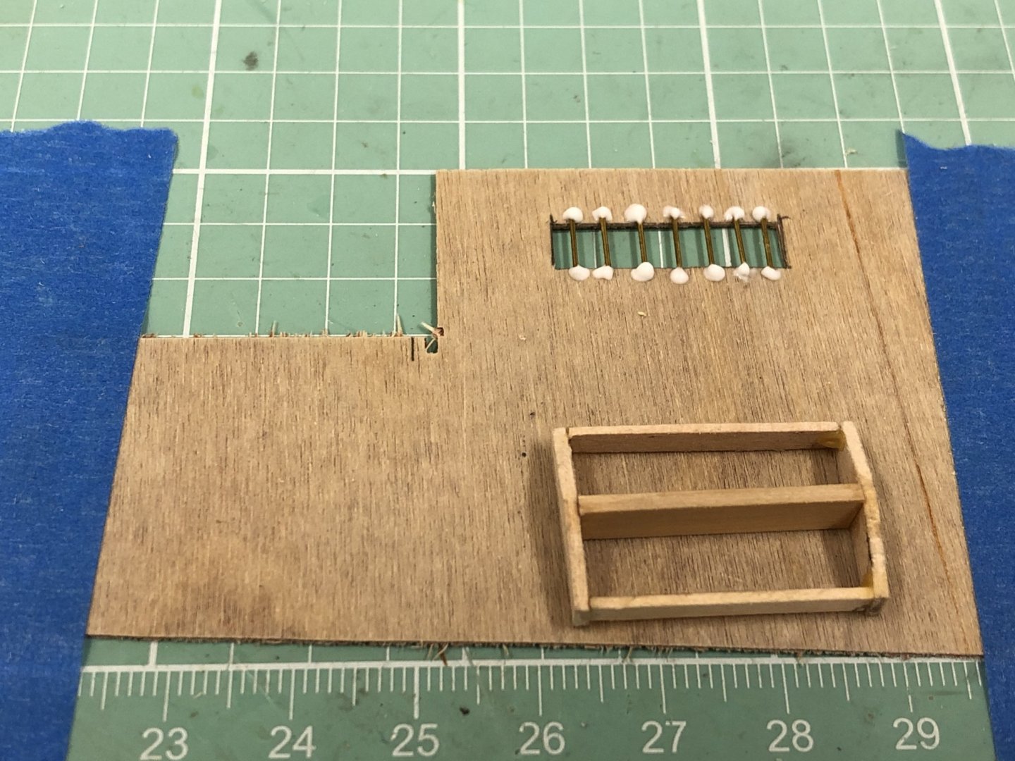
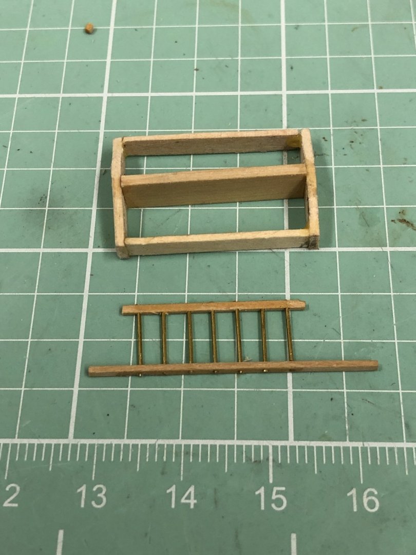
Working the skylight for the after deck house. I fabed the framework using end pieces of 1/16" basswood and templates from the plans. The sides are 1/16 X 1/8 strips and the center is 1/16 X 1/4 sanded down to 7/32. Now for the brass rod bars across the "windows". My first thought was cutting a frame from the 1/32 strip wood and gluing short pieces of the 1/64" brass rod provided across the opening. I did that but the 1/32" sheet split when I tried to cut from the larger piece it was part of. The 1/32" strip wood is quite fragile along the grain line, especially when trying to cut it with a razor knife (Xacto et al). So I rummaged through my wood pile and found some 1/32" plywood (three plies) that I used for something (I forget what) and redid the the frame opening and added the wires to that. The wires are glued on with Weldbond which will dry clear so it will not be as noticeable as it is now and maybe it will look okay when painted white per the instructions. After looking at the problem a bit more I decided to try another approach. I have some 1/32 X 1/32 (.031125") boxwood and thought if I could drill a hole (in the center) big enough to get the brass wire (.019") through (without breaking it) it might be a better looking solution (no glue "bumps". So I tried. Getting the holes (.020" - #76 bit) drilled in the center is a challenge but I found using a sharp awl to mark the hole location made it easier (but not easy) to get the hole centered and not wander off. I decided on seven bars per window so needed two pieces with seven holes each. It took some time but I finally got one set assembled. I used thin CA to "seal" the wire in the wood. I need to trim the lower bar and make another set but I think this is the way I am going to go for the skylight.
- 166 replies
-
- 2
-
-
- fannie a gorham
- finished
- (and 1 more)
-
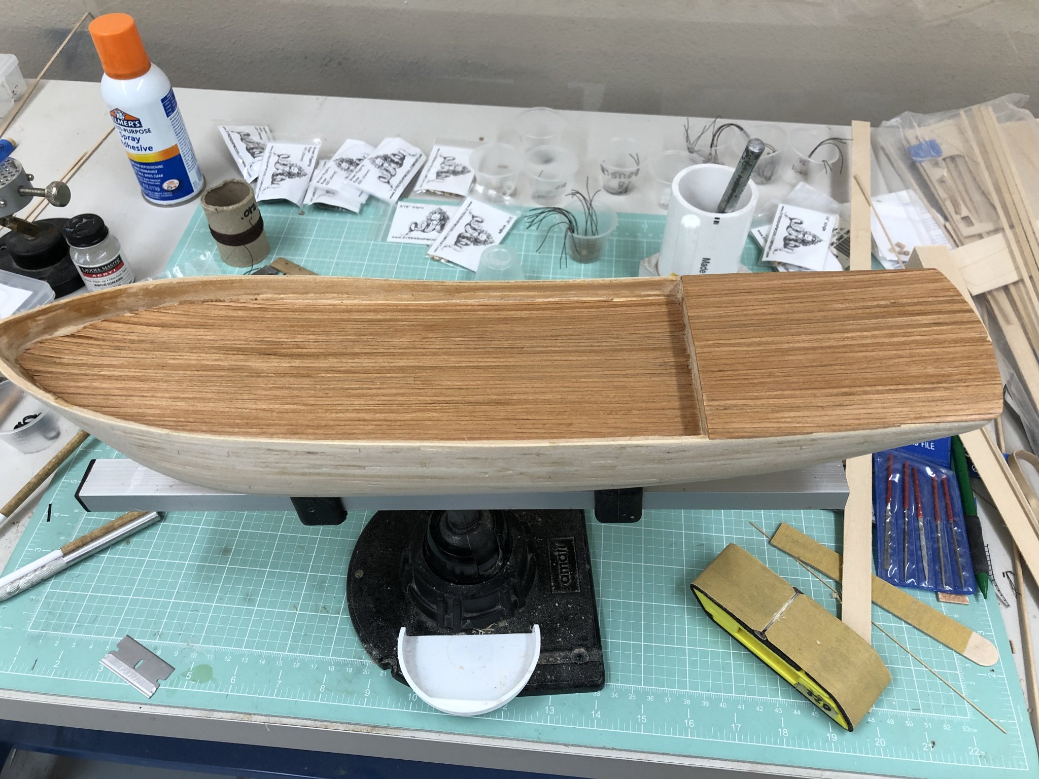
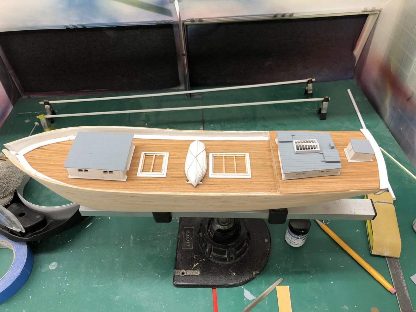
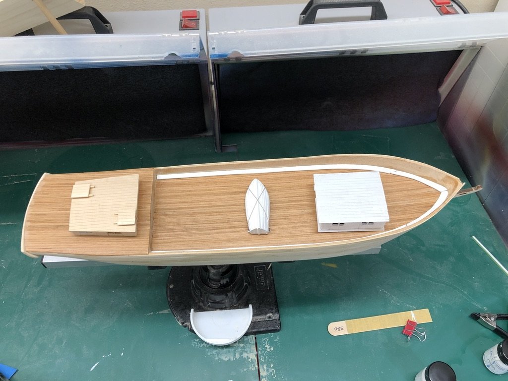
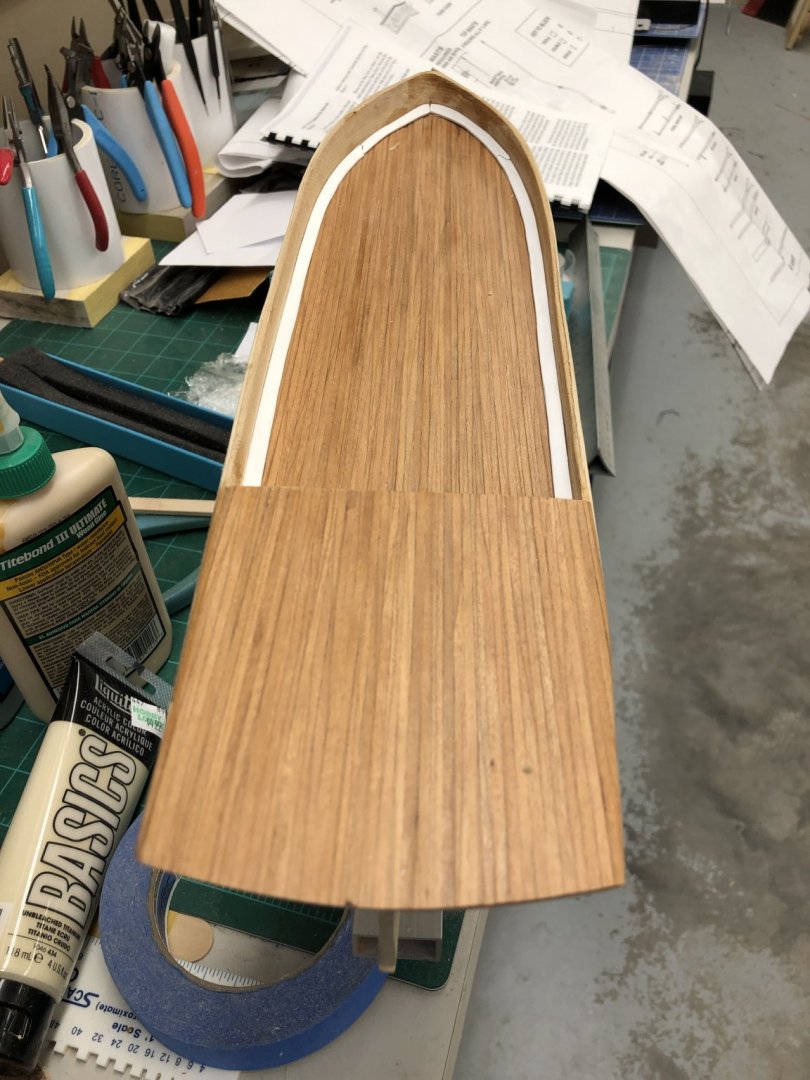
I am continuing to work the deck furniture as I am having trouble staying motivated working on the masts. I did get the transom installed. After rereading the instructions and careful study of the limited drawings I think the transom is supposed to extend up so the top of the transom piece is even with the top of the taffrail waterway. For whatever reason, probably my not shaping the stern correctly, the provided transom is too short to cover both the taffrail waterway and the stern planking. So the taffrail waterway will run on top of the transom and then the taffrail bottom rail on top of the waterway. I am guessing no one will notice. Anyway, here is the hull with the primer painted forward deck house and the in-process after deck house along with the completed lifeboat.
- 166 replies
-
- 4
-
-
- fannie a gorham
- finished
- (and 1 more)
-
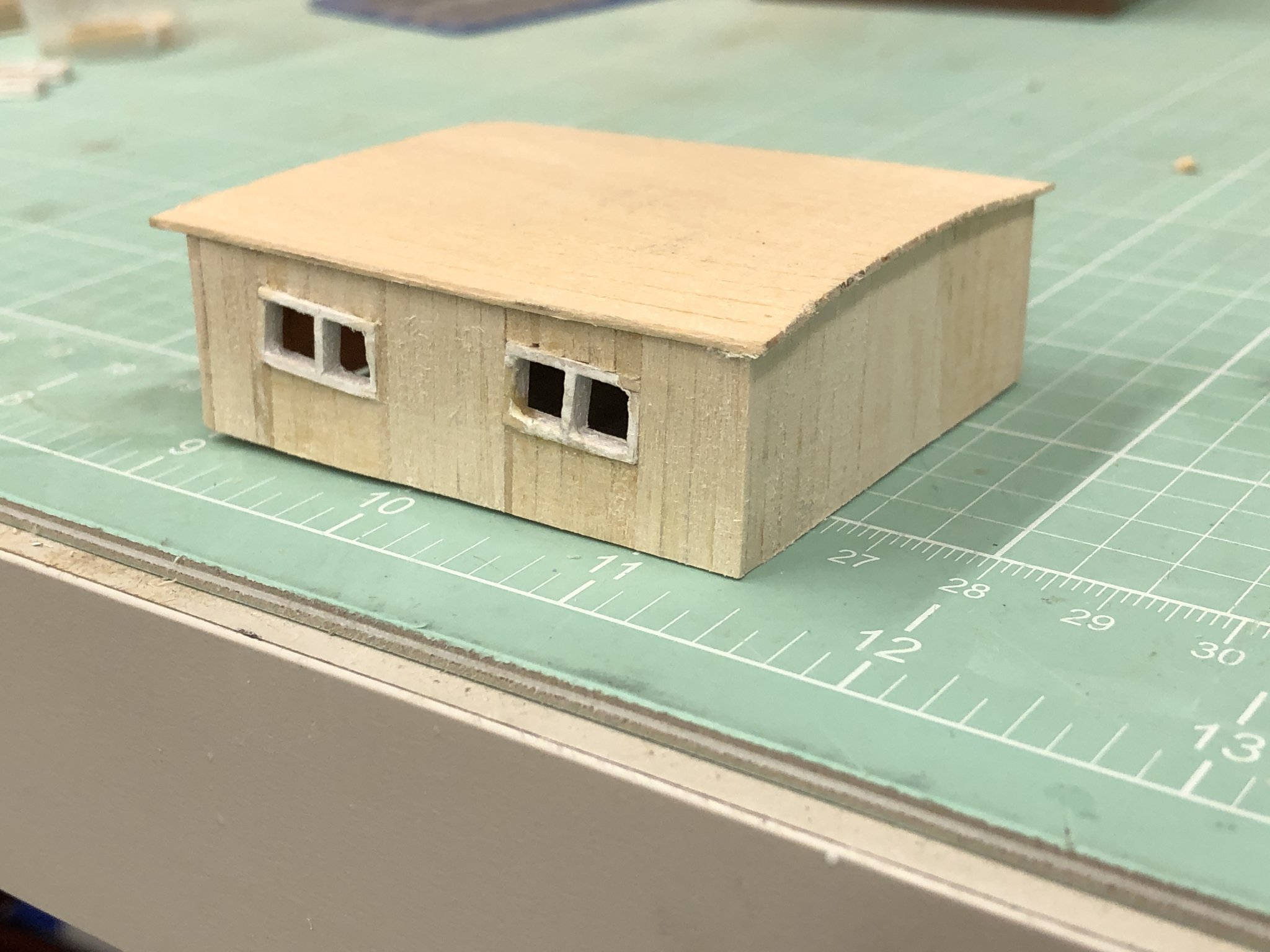
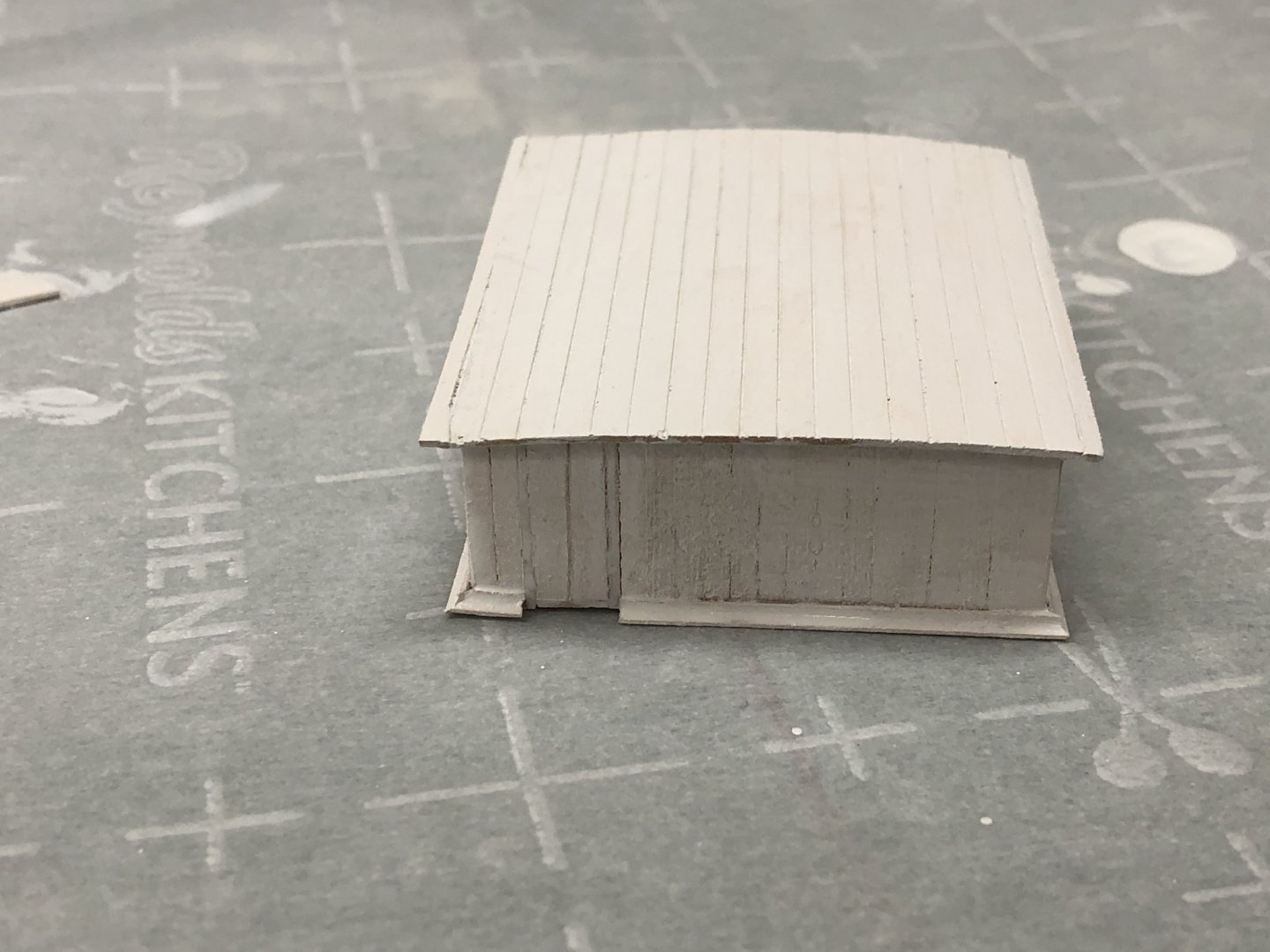
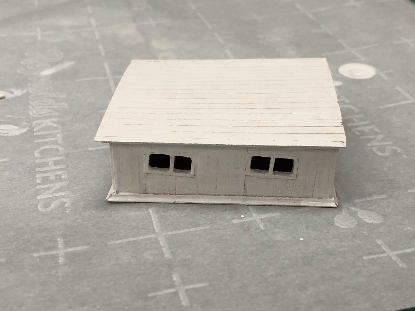
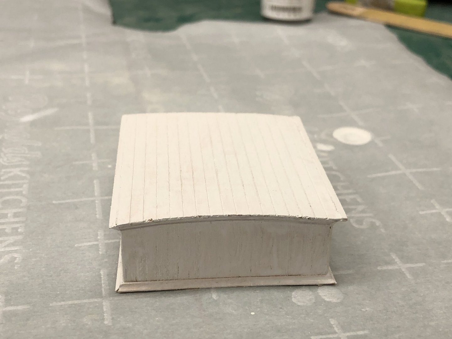
The forward deck house assembly is complete except for the stove exhaust (I think). The side view on Sheet 3 seems to show a sliding hatch but it does not show on the plan views on sheet 3 or 1 so I guess there is not one. Here is the fwd deck house after the primer coat.

- 166 replies
-
- 3
-
-
- fannie a gorham
- finished
- (and 1 more)
-
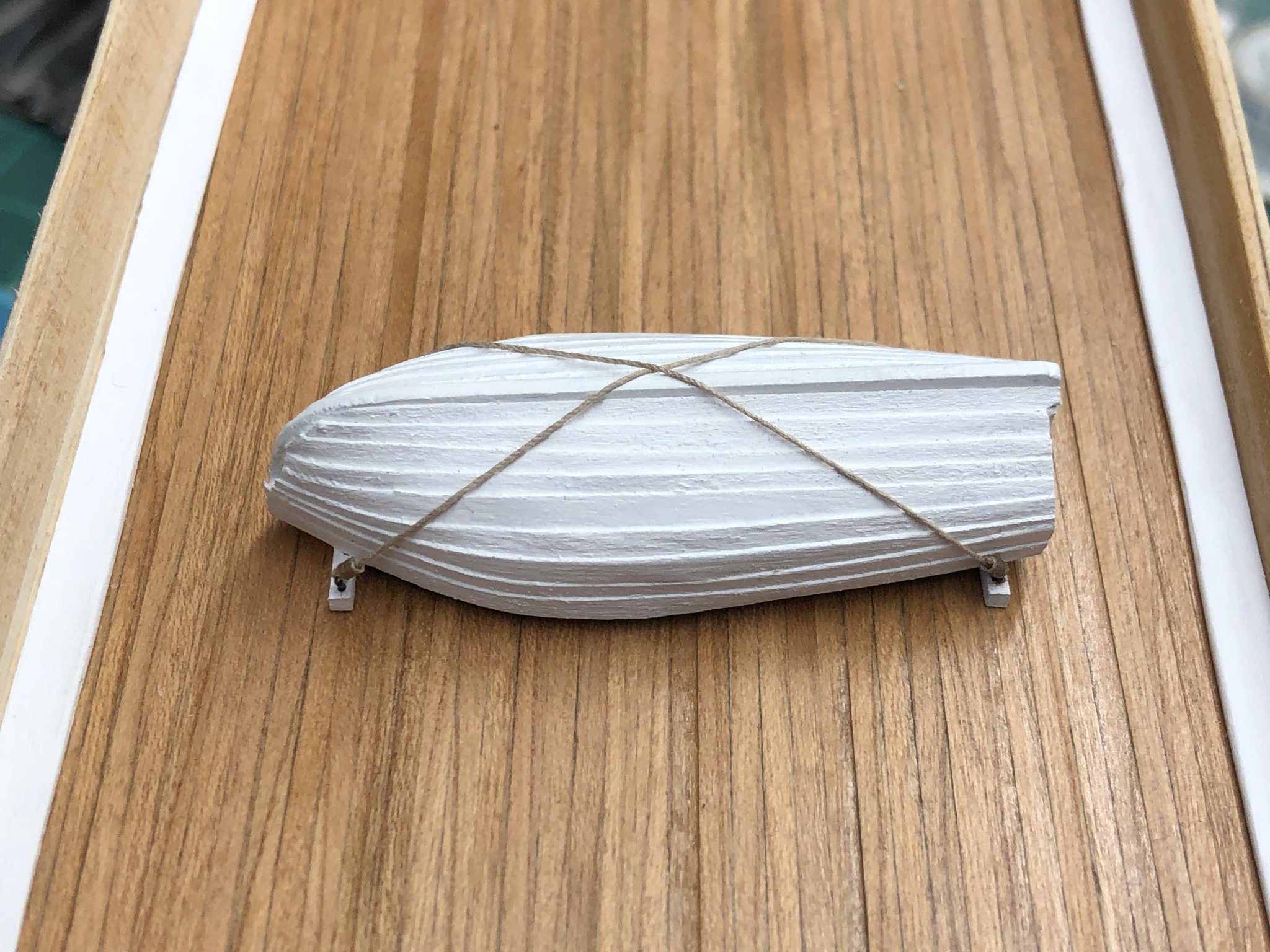
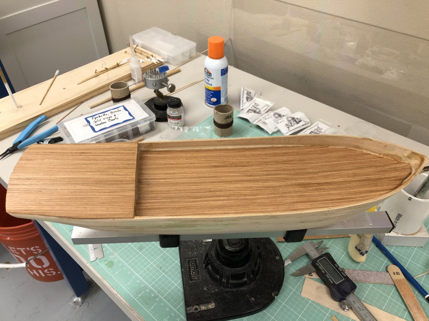
I finally have one thing "done". Here is the lifeboat in its cradle and lashed down on the deck approximately where it will be on the finished model. For those interested this is the 2 1/8" boat kit from Model Shipways with HO scale 1" X 8" boards from Northeastern Scale Lumber glued on the solid hull to get the clinker "look".


- 166 replies
-
- 4
-
-
- fannie a gorham
- finished
- (and 1 more)
-
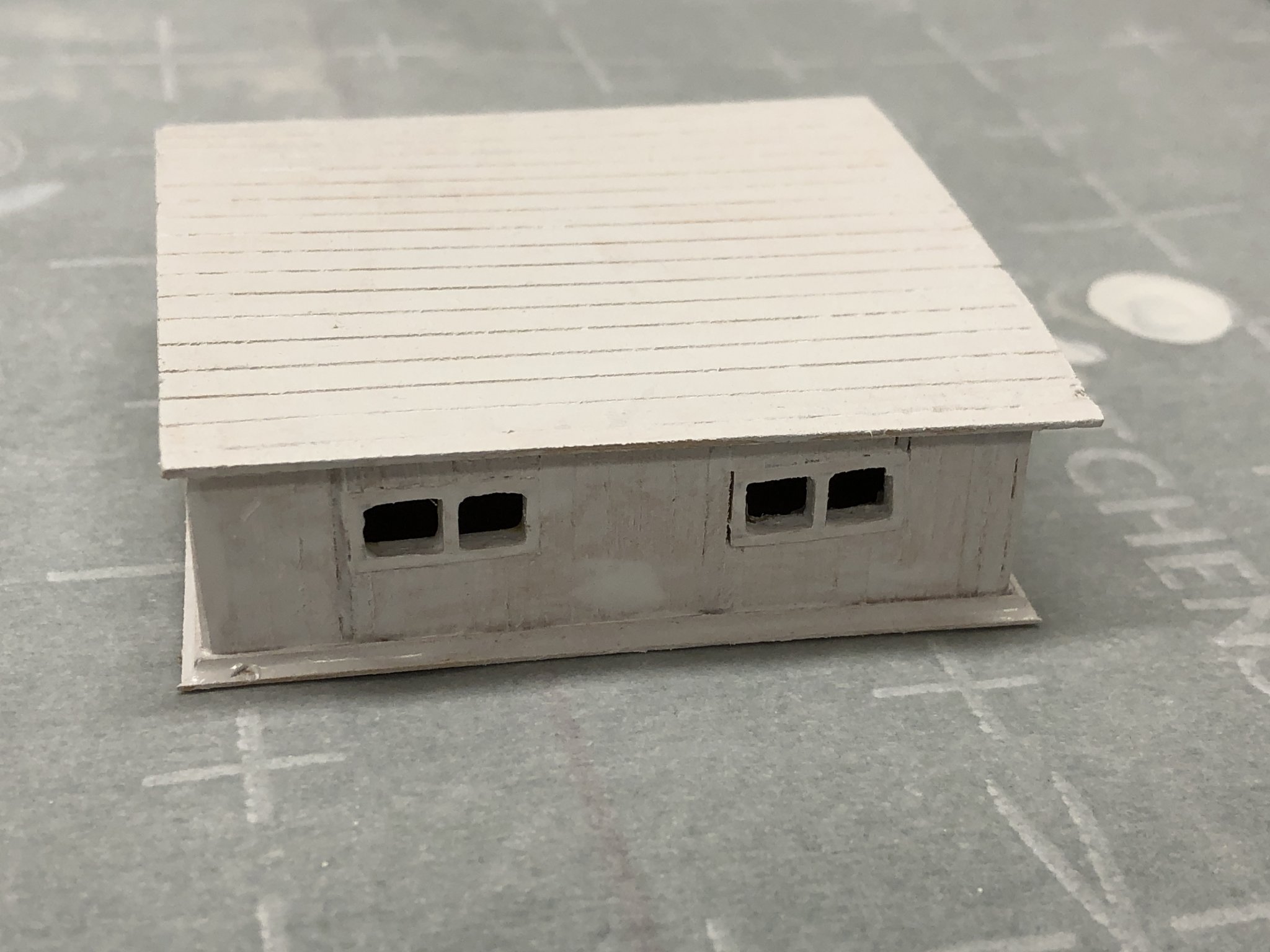
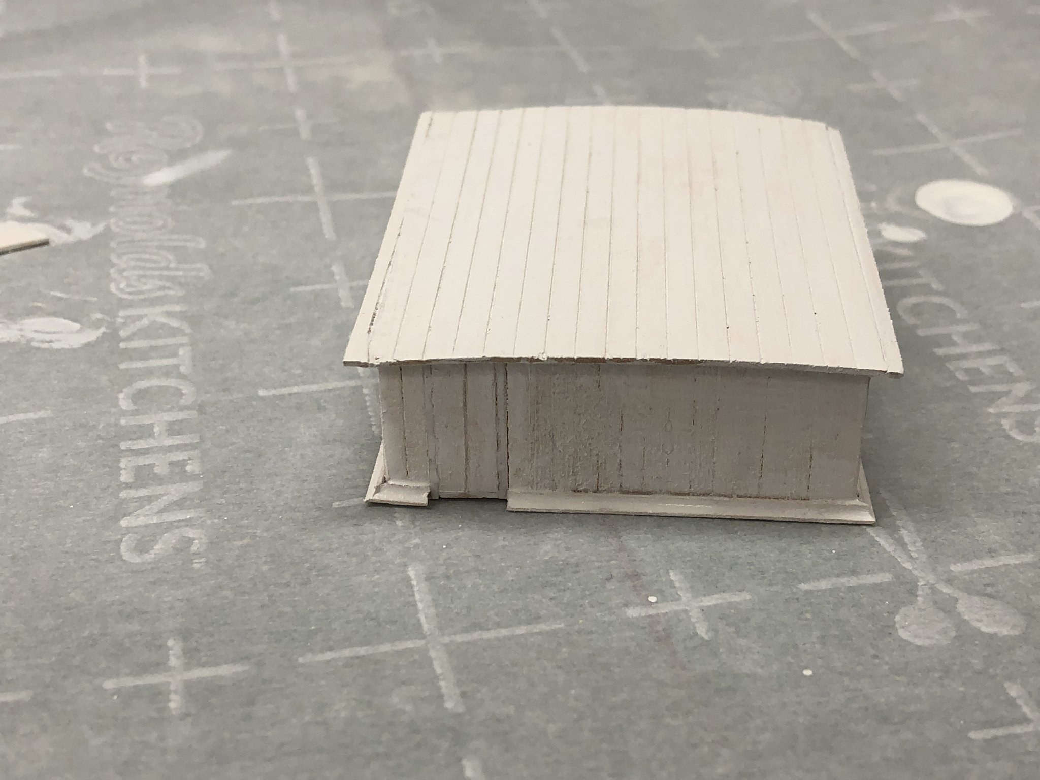
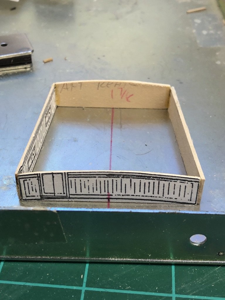
I was having so much playing with my furniture building jig I went and assembled the aft deck house too. Somewhat more challenging since it is not rectangular and without a plan of what it looks like at deck level (the plan view provided shows the roof outline) I had to come up with another way to get the correct shape. My method was to rubber cement copies of the deck house drawings to the 1/32" sheet provided and sand the sheets to the lines representing the top and bottom of each side, disregarding the camber in the fore and aft pieces (straight across the bottom). I then marked the measured centerline on the fore and aft pieces and drew a line perpendicular to the wall of the furniture jig (red in picture). I clamped the forward end to the wall of the jig with the center on the red line and then used the magnetic "clamps" to position the aft end on the centerline approximately where it would be. I used the two side pieces to establish exactly where the aft end should be and used more magnetic clamps to hold them in place against the end pieces. I carefully moved the pieces apart one at a time and added wood glue to the joints and then made one last check that everything looked "trapezoidal". I will remove the drawings from the wood after I cut out where the windows go. Note that one side has the plan on the inside since the drawing shows only one side of the structure. I drill holes from the inside to locate the top of the window opening so I can cut them on the outsiude. Here is the aft deck house ready to have the roof installed.
- 166 replies
-
- 1
-
-
- fannie a gorham
- finished
- (and 1 more)
-
I installed the waterways, including my somewhat indifferent attempt at scarf joints. I was not too concerned about the junction at the bow as this will be hidden under the bowsprit. I did not install the stern waterway yet as it is not clear to me from the drawings whether the transom piece extends to the top of the waterway or ends at the top of the deck planking. In fact the entire stern layout is confusing. The instructions (page 5) call for a 5/16" wide waterway at the stern with the 1/8" wide taffrail base on top but the drawing (sheet 1 - Plan View) only shows (as best I can tell) the taffrail base. Admittedly there is only 1/16" of the waterway protruding forward of the taffrail base but it should show on the plans somewhere. My plan is to install the transom even with the top of the quarterdeck decking now and have the waterway extend over the transom piece (to cover the seam between the transom and the decking and any sanding marks made getting the transom even with the decking). Probably should have don this before I put the Wipe-on-Poly on the quarterdeck but that is how you learn. So here is the hull with the waterways (except at the stern) installed.

- 166 replies
-
- 2
-
-
- fannie a gorham
- finished
- (and 1 more)
-
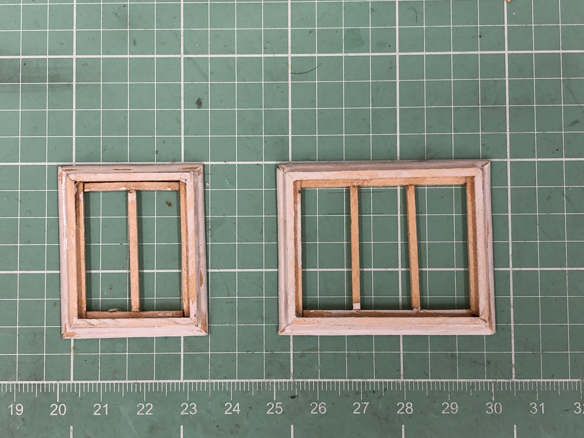
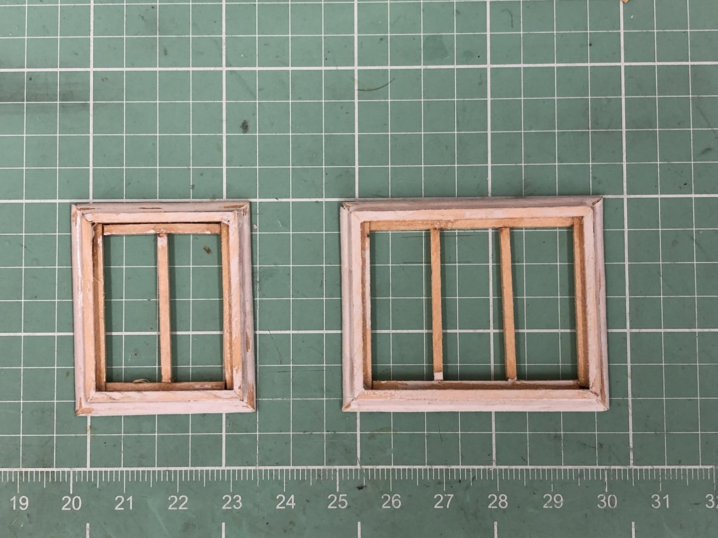
Continuing to work on the fwd deck house. I used the kit provided 1/32" sheet deck planking for the roof - it will be painted gray. The sides I plan ked with left over hull planking strips (1/32" X 3/32". I had to muse a few smaller pieces when necessary around the windows. Here it is with the front and one side ready for primer. The sides of the deck houses will be white like the inside of the bulwarks and waterways. When I looked at the aft deck house I realized that the windows I made from forward will be too big aft so I found my "window jig", and am making another set about half as tall as the ones on the fwd house.
- 166 replies
-
- 2
-
-
- fannie a gorham
- finished
- (and 1 more)
-
Speaking of deck houses - here is the forward deck house "going up" in the furniture building jig. I used the disk sander to take the 1/32" sheet with the deck house outline rubber glued to it down to the lines. I did the forward one first because it is square and therefore requires less thought. I will cut out the windows and add the additional "siding then the structure is more secure (like has a roof) and maybe a floor (painted black)
- 166 replies
-
- 2
-
-
- fannie a gorham
- finished
- (and 1 more)
-
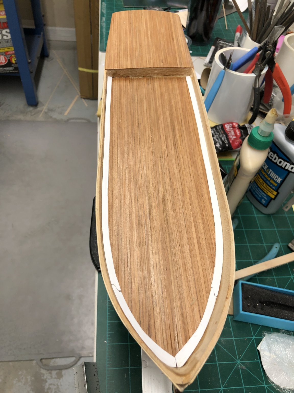
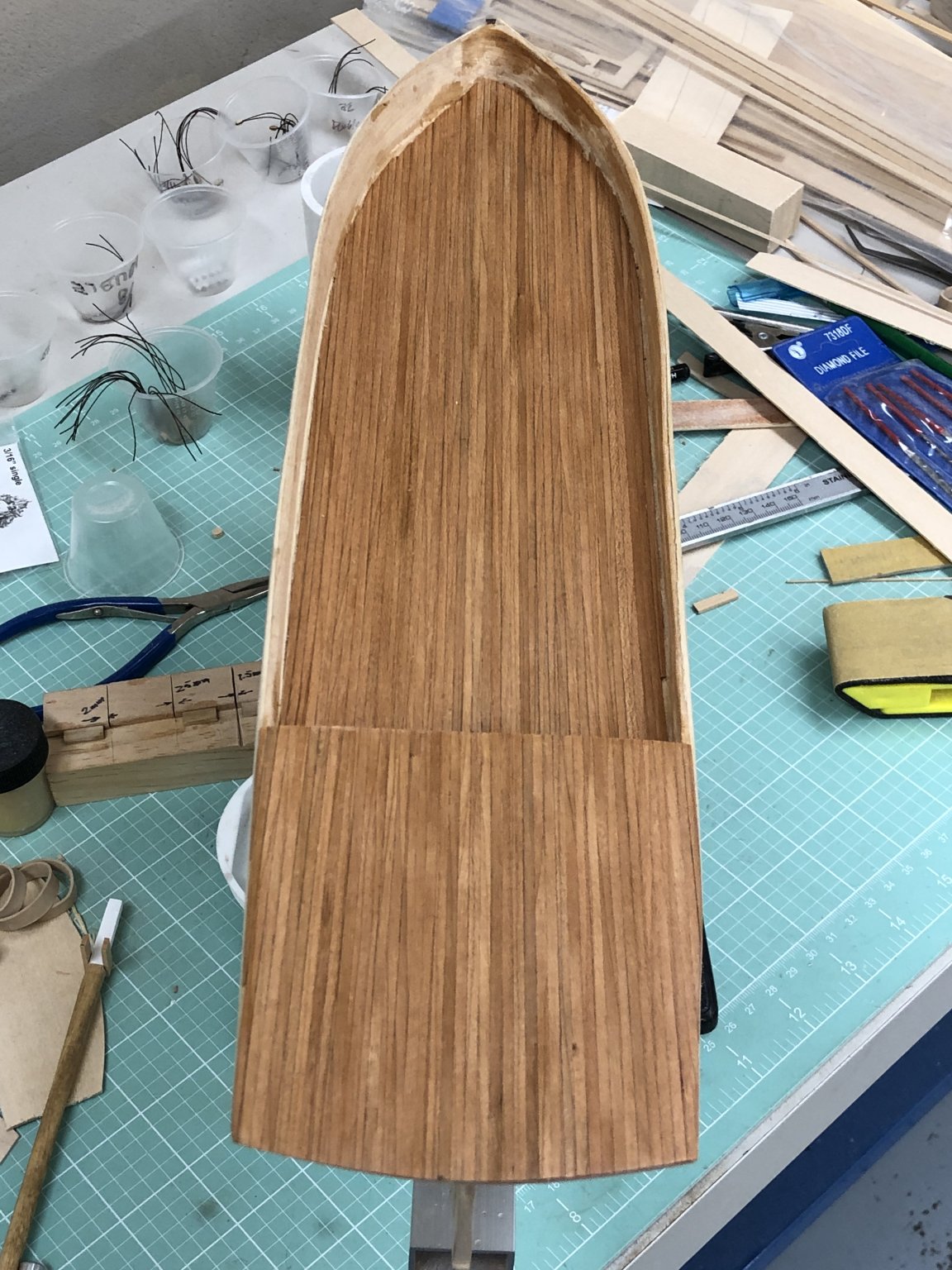
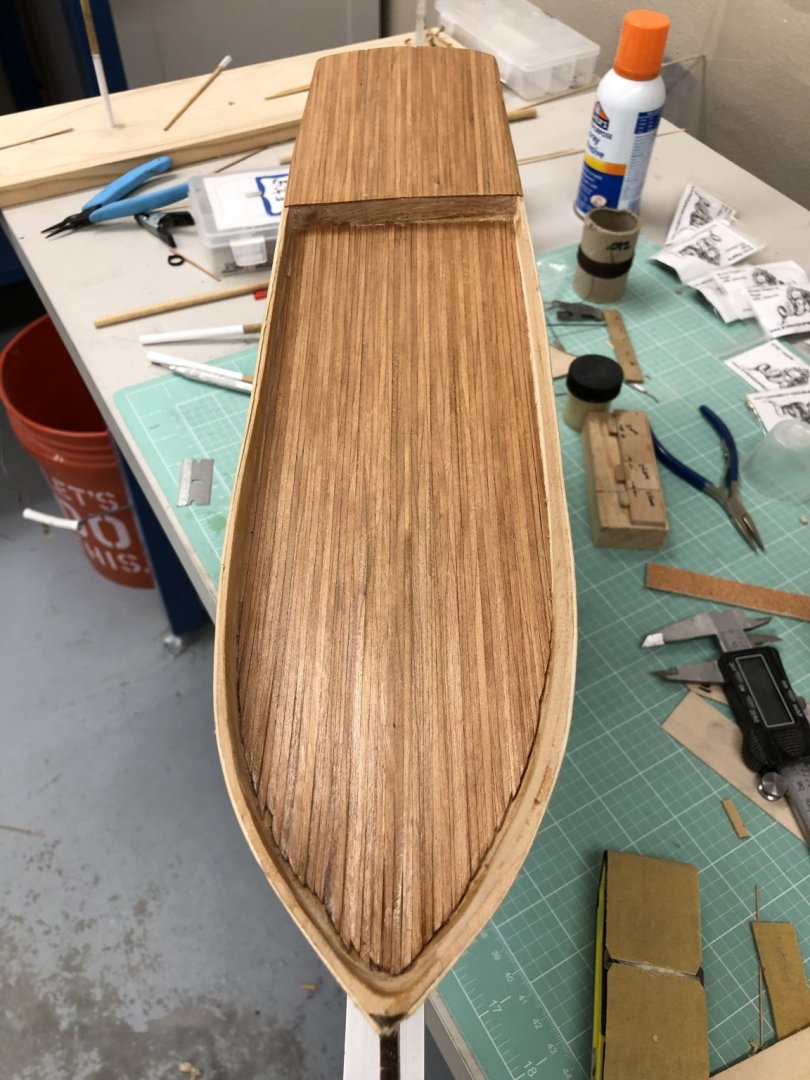
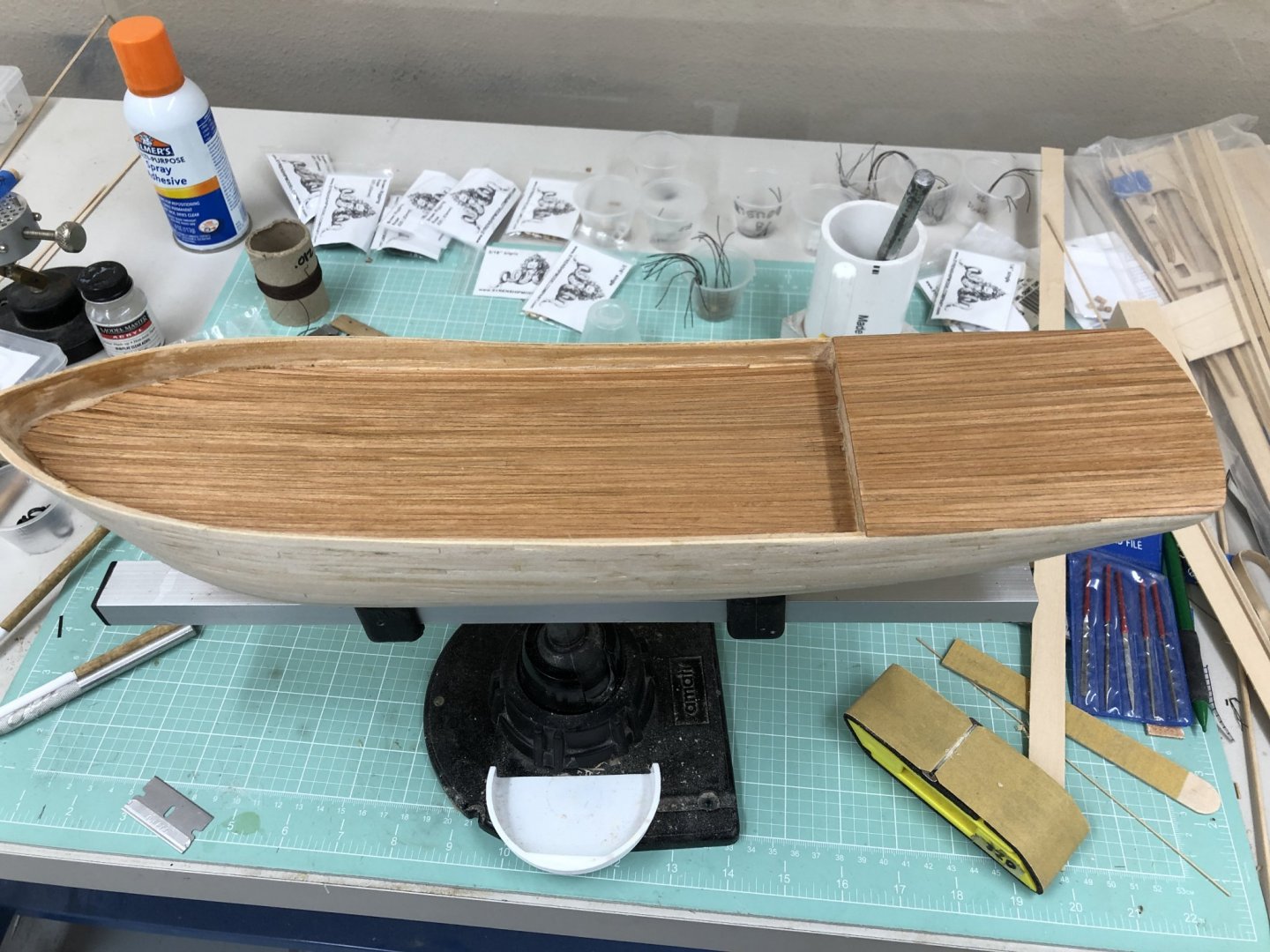
Deck planking is complete - four coats of Wipe-on-Poly with 320 grit sanding between coats. Waterways will be installed next then paint the bulwarks (waterways act as "splatter shield" while bulwarks are painted - hopefully).

- 166 replies
-
- 4
-
-
- fannie a gorham
- finished
- (and 1 more)